US6584301B1 - Inductive reader device and method with integrated antenna and signal coupler - Google Patents
Inductive reader device and method with integrated antenna and signal couplerDownload PDFInfo
- Publication number
- US6584301B1 US6584301B1US09/578,433US57843300AUS6584301B1US 6584301 B1US6584301 B1US 6584301B1US 57843300 AUS57843300 AUS 57843300AUS 6584301 B1US6584301 B1US 6584301B1
- Authority
- US
- United States
- Prior art keywords
- coil element
- transponder
- coil
- receiver
- radio frequency
- Prior art date
- Legal status (The legal status is an assumption and is not a legal conclusion. Google has not performed a legal analysis and makes no representation as to the accuracy of the status listed.)
- Expired - Lifetime
Links
Images
Classifications
- G—PHYSICS
- G06—COMPUTING OR CALCULATING; COUNTING
- G06K—GRAPHICAL DATA READING; PRESENTATION OF DATA; RECORD CARRIERS; HANDLING RECORD CARRIERS
- G06K7/00—Methods or arrangements for sensing record carriers, e.g. for reading patterns
- G06K7/10—Methods or arrangements for sensing record carriers, e.g. for reading patterns by electromagnetic radiation, e.g. optical sensing; by corpuscular radiation
- G06K7/10009—Methods or arrangements for sensing record carriers, e.g. for reading patterns by electromagnetic radiation, e.g. optical sensing; by corpuscular radiation sensing by radiation using wavelengths larger than 0.1 mm, e.g. radio-waves or microwaves
- G06K7/10158—Methods or arrangements for sensing record carriers, e.g. for reading patterns by electromagnetic radiation, e.g. optical sensing; by corpuscular radiation sensing by radiation using wavelengths larger than 0.1 mm, e.g. radio-waves or microwaves methods and means used by the interrogation device for reliably powering the wireless record carriers using an electromagnetic interrogation field
- G06K7/10178—Methods or arrangements for sensing record carriers, e.g. for reading patterns by electromagnetic radiation, e.g. optical sensing; by corpuscular radiation sensing by radiation using wavelengths larger than 0.1 mm, e.g. radio-waves or microwaves methods and means used by the interrogation device for reliably powering the wireless record carriers using an electromagnetic interrogation field including auxiliary means for focusing, repeating or boosting the electromagnetic interrogation field
- G—PHYSICS
- G06—COMPUTING OR CALCULATING; COUNTING
- G06K—GRAPHICAL DATA READING; PRESENTATION OF DATA; RECORD CARRIERS; HANDLING RECORD CARRIERS
- G06K7/00—Methods or arrangements for sensing record carriers, e.g. for reading patterns
- G06K7/0008—General problems related to the reading of electronic memory record carriers, independent of its reading method, e.g. power transfer
- H—ELECTRICITY
- H04—ELECTRIC COMMUNICATION TECHNIQUE
- H04B—TRANSMISSION
- H04B5/00—Near-field transmission systems, e.g. inductive or capacitive transmission systems
- H04B5/40—Near-field transmission systems, e.g. inductive or capacitive transmission systems characterised by components specially adapted for near-field transmission
- H04B5/48—Transceivers
- H—ELECTRICITY
- H04—ELECTRIC COMMUNICATION TECHNIQUE
- H04B—TRANSMISSION
- H04B5/00—Near-field transmission systems, e.g. inductive or capacitive transmission systems
- H04B5/20—Near-field transmission systems, e.g. inductive or capacitive transmission systems characterised by the transmission technique; characterised by the transmission medium
- H04B5/24—Inductive coupling
- H04B5/26—Inductive coupling using coils
- H04B5/266—One coil at each side, e.g. with primary and secondary coils
- H—ELECTRICITY
- H04—ELECTRIC COMMUNICATION TECHNIQUE
- H04B—TRANSMISSION
- H04B5/00—Near-field transmission systems, e.g. inductive or capacitive transmission systems
- H04B5/40—Near-field transmission systems, e.g. inductive or capacitive transmission systems characterised by components specially adapted for near-field transmission
- H04B5/45—Transponders
Definitions
- the present inventionrelates generally to inductive reader devices for use with contactless smartcards, radio frequency identification devices and other transponders, and in particular to an inductive reader device with an integrated antenna and signal coupler.
- Inductive reader devicesare known for use with transponders, such as contactless smartcards and radio frequency identification devices.
- the readertypically provides a radio frequency excitation signal.
- electromagnetic coupling via the excitation signalpowers the transponder and enables the transponder to generate a radio frequency response signal.
- This response signalis electromagnetically coupled to the reader.
- a data signal from the transponder included in the response signalis received by the reader and used for processing.
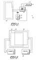
- FIG. 1is a block diagram showing schematically a known inductive reader device 10 .
- Reader device 10includes a transmitter 12 , a receiver 14 an antenna 16 and a transformer 18 .
- Transmitter 12generates a radio frequency excitation signal using a signal source 20 , which is typically controlled by a control circuit and a modulator that modulate commands onto the excitation signal.
- Transmitter 12is directly connected to antenna 16 .
- Antenna 16is a coil having a predetermined inductance.
- Antenna 16is typically implemented as a coil etched on a printed circuit board.
- Antenna 16is generally made to consume as large an area as available in order to improve electromagnetic coupling between the reader device 10 and a transponder.
- Antenna 16is directly connected to transformer 18 .
- Transformer 18is a discrete component that is separate and apart from antenna 16 .
- Transformer 18is connected to receiver 14 .
- Transformer 18does not inductively couple to a transponder.
- Transformer 18is used to electrically receive from antenna 16 a data component of the modulated response signal returned by a transponder. This signal is then received by the receiver 14 , which is directly connected to the transformer 18 .
- the received signalis used by the reader circuit in accordance with the application, for example, security identification, smartcard transactions, etc.
- Transformer 18is physically large and consumes valuable printed circuit board area. Transformer 18 is relatively expensive as well. In addition, some discrete transformer components are prone to failure, impacting the reliability of the product. Also, the characteristics of the transformer are required to be matched to the antenna, which may require custom transformer components for some reader devices.
- FIG. 2shows a known reader device 50 that eliminates the need for a discrete transformer, such as transformer 18 .
- Reader device 50includes a transmitter 52 , a receiver 54 , a transmitter antenna 56 and a receiver antenna 58 .
- Transmitter 52generates an excitation signal that is emitted by transmitter antenna 56 .
- Transmitter antenna 56is a coil. Electromagnetic coupling is used to transmit the excitation signal to a transponder brought in close proximity to transmitter antenna 56 .
- the receiver antenna 58is provided for coupling to the transponder to receive the responsive radio frequency signal.
- Receiver antenna 58is directly connected to receiver 54 to transfer the received responsive signal to the receiver.
- transmitter antenna 56 and receiver antenna 58share an available antenna area 60 .
- the antennas 56 , 58are implemented as traces in a printed circuit board.
- the antennasare electrically isolated.
- the antennaspartially overlap each other for mutual flux cancellation, which is required to isolate the transmitter and the receiver for proper circuit operation. Since the antennas must overlap partially, the total antenna area cannot be used for any one antenna. Therefore the size of both antennas is compromised in comparison to the total available antenna area.
- the reduced antenna areareduces the operating range of the reader device. This may be undesirable, in particular, for small portable reader devices.
- FIG. 1is a schematic block diagram showing a prior art reader device that requires a discrete transformer for coupling a responsive signal from a transponder to a receiver.
- FIG. 2is a schematic block diagram of a prior art reader device that uses two isolated antennas to separately transmit and receive radio frequency signals.
- FIG. 3is a schematic block diagram of a reader device in accordance with the present invention including an integrated antenna and signal coupler.
- an inductive reader devicein accordance with the present invention includes a transmitter, a receiver, a first coil element and a second coil element.
- the first coil elementis connected to the transmitter.
- the first coil elementemits and receives radio frequency signals including a data signal from a transponder. Radio frequency signals from the transponder are electromagnetically coupled over the air to the first coil element.
- the second coil elementis directly connected to the receiver and inductively coupled to the first coil element by proximate spacing to the first coil element. More specifically, the second coil element is sized substantially smaller than the first coil element and is selected to have a self-inductance and mutual inductance with the first coil element.
- a methodfor communicating between a transponder and an inductive reader device.
- a first coil element connected to a transmitter of the inductive reader deviceis coupled with the transponder via inductive coupling. This typically entails bringing the transponder in close proximity to the reader.
- a radio frequency signalis produced by the transponder in response to the inductive coupling between the transponder and the first coil element.
- the radio frequency signalincludes a data signal.
- a second coil element connected to a receiver of the inductive reader deviceis inductively coupled with the first coil element such that the second coil element receives a coupled signal from the first coil element and the receiver receives the coupled signal from the second coil element.
- the coupled signalincludes the data signal from the transponder.
- the first coil element and the second coil elementare both implemented as traces on a printed circuit board with the second coil element located within the interior area of the first coil element to provide a predetermined mutual coupling between the first coil element and the second coil element.
- the second coil elementadvantageously eliminates the need for a discrete transformer to serve as a signal coupler for the receiver.
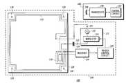
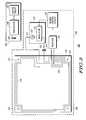
- FIG. 3is a block diagram of a radio frequency communication system 100 in accordance with the present invention.
- System 100includes a transponder 102 and a reader device 104 .
- Reader device 104 and transponder 102communicate over the air with each other when placed in close proximity to each other. More specifically, reader device 104 produces a radio frequency excitation signal that is electromagnetically coupled to transponder 102 . In response to the excitation signal, transponder 102 is energized to transmit a responsive radio frequency signal.
- Transponder 102includes a coil element 106 , a transceiver 108 , and a control circuit 110 .
- Coil element 106serves as an antenna for receiving the excitation signal and emitting the responsive signal.
- Transceiver 108includes a transmitter for transmitting or modulating a response signal and a receiver for receiving an excitation signal, which may or may not include data.
- Control circuit 110determines the data to be supplied in the response signal as well as the actions to be taken in response to the excitation signal. Control circuit 110 varies according to the application for transponder 102 .
- transponder 102is a smartcard or radio frequency identification device.
- Reader device 104includes a transmitter 112 , a receiver 114 , a first coil element 116 , a second coil element 118 and a reader control circuit 120 .
- Transmitter 112generates an excitation signal under control of reader control circuit 120 .
- Transmitter 112is directly connected to first coil element 116 . More specifically, first coil element 116 is preferably directly connected to transmitter 112 at a first terminal 121 and is preferably capacitively coupled to transmitter 112 at a second terminal 123 .
- Capacitor 124couples the transmitter 112 to the first coil element 116 at second terminal 123 and is selected to resonate with the inductance of the coil element at the operating frequency of the communication system.
- First coil element 116serves as an antenna for emitting and receiving radio frequency signals. More specifically, first coil element 116 emits an excitation signal generated by transmitter 112 and receives a responsive signal from a transponder. A second coil element 118 is directly connected to receiver 114 . Second coil element 118 supplies the responsive signal to receiver 114 . In accordance with the present invention, second coil element 118 serves as a signal coupler to supply the responsive signal from a transponder to receiver 114 . More specifically, second coil element 118 is placed in spatial relationship to first coil element 116 such that a predetermined intentional mutual inductance between first coil element 116 and second coil element 118 permits a responsive signal to be coupled to receiver 114 . Control circuit 120 receives the data in the responsive signal from receiver 114 .
- first coil element 116 and second coil element 118are implemented as traces on printed circuit board 128 .
- Printed circuit board 128defines an available area for an antenna. To maximize system operating range, first coil element 116 is etched in printed circuit board 128 to maximize the size of first coil element 116 in relation to the available antenna area.
- First coil element 116is routed substantially around the perimeter of printed circuit board 128 .
- the perimeter of printed circuit board 128has a generally rectangular or square configuration.
- first coil element 116has a generally rectangular configuration.
- Mounting holes 130which are used to mount printed circuit board 128 to another printed circuit board comprising the reader, prevent the first coil element 116 from being more rectangular.
- First coil element 116alternatively has a circular, oval or other configuration, typically conforming to a shape of the housing for the coil element.
- Second coil element 118is substantially smaller than first coil element 116 . This, in part, prevents second coil element 118 from substantially coupling with transponder 102 . Second coil element 118 is placed in close proximity to first coil element 116 to form a transformer. To minimize the size of second coil element 118 and maintain adequate coupling to the first coil element, second coil element 118 is configured near a corner of first coil element 116 . Second coil element 118 is preferably placed in the same plane of the printed circuit board as first coil element 116 . Second coil element 118 preferably has a generally rectangular configuration. Alternatively, second coil element 118 has a circular, oval or other configuration.
- First coil element 116is shown in FIG. 3 as a coil with two turns.
- Second coil element 118is a coil with three turns. The number and configuration of turns will vary in part with an inductance required for operation of the reader.
- first coil element 116 and second coil element 118are etched in a printed circuit board.
- first coil element 116 and second coil element 118are implemented as coiled wire in a nonconductive material or substrate.
- first coil element 116 and second coil element 118are implemented by any suitable conductive material arranged in a coil, for example, conductive ink or insulated wire.
- Transmitter 112 , receiver 114 and reader control circuit 120are selected based on the application for reader device 104 .
- Reader control circuit 120is preferably microprocessor based. Reader control circuit 120 generates data that modulates transmitter 112 for a read/write system. For a read-only system, reader control circuit 120 need not generate a modulated (i.e., with data or a write command) signal to the transponder.
- Transmitter 112preferably includes an oscillator 122 for generating the radio frequency excitation signal and a modulator 119 , where required, for modulating the radio frequency excitation signal.
- Receiver 114preferably receives and demodulates a data signal included in a responsive signal received by second coil element 118 due to its inductive coupling with first coil element 116 .
- transmitter 112In operation, transmitter 112 generates a radio frequency excitation signal under control of reader control circuit 120 .
- the excitation signalis emitted by first coil element 116 .
- transponder 102When a transponder, such as transponder 102 is brought in close proximity to reader device 104 , transponder 102 receives the excitation signal. More specifically, coil element 106 receives the excitation signal and uses the energy of the excitation signal to power circuitry on transponder 102 .
- the control circuitthen drives transceiver 108 to emit an appropriate response signal. In a preferred embodiment, the response signal is a modulated version of the excitation signal.
- the response signal emitted by transponder 102is received by first coil element 116 .
- second coil element 118Due to the size of second coil element 118 , there is no substantial coupling of second coil element 118 with transponder 102 . However, mutual inductance caused by the spatial relationship between first coil element 116 and second coil element 118 induces in second coil element 118 a signal that includes the response signal from transponder 102 . This responsive signal is made available at the input of receiver 114 , permitting receiver 114 to receive and demodulate data associated with the responsive signal. This data is transferred to the reader control circuit 120 for operation in accordance with the application implemented by reader device 104 .
- an inductive reader devicewith an integrated antenna and signal coupler.
- the inductive reader devicedoes not require a discrete transformer component directly coupled to the main antenna. Rather, a second coil element is integrated in the antenna element space to form an integrated transformer to couple a responsive signal from a transponder to a receiver in the reader.
- the second coil elementutilizes printed circuit board space that was otherwise unused and frees up space occupied by the discrete transformer device.
Landscapes
- Engineering & Computer Science (AREA)
- Physics & Mathematics (AREA)
- Electromagnetism (AREA)
- General Physics & Mathematics (AREA)
- Health & Medical Sciences (AREA)
- Toxicology (AREA)
- Artificial Intelligence (AREA)
- Computer Vision & Pattern Recognition (AREA)
- Computer Networks & Wireless Communication (AREA)
- Theoretical Computer Science (AREA)
- General Health & Medical Sciences (AREA)
- Signal Processing (AREA)
- Near-Field Transmission Systems (AREA)
Abstract
Description
Claims (39)
Priority Applications (1)
| Application Number | Priority Date | Filing Date | Title |
|---|---|---|---|
| US09/578,433US6584301B1 (en) | 2000-05-25 | 2000-05-25 | Inductive reader device and method with integrated antenna and signal coupler |
Applications Claiming Priority (1)
| Application Number | Priority Date | Filing Date | Title |
|---|---|---|---|
| US09/578,433US6584301B1 (en) | 2000-05-25 | 2000-05-25 | Inductive reader device and method with integrated antenna and signal coupler |
Publications (1)
| Publication Number | Publication Date |
|---|---|
| US6584301B1true US6584301B1 (en) | 2003-06-24 |
Family
ID=24312864
Family Applications (1)
| Application Number | Title | Priority Date | Filing Date |
|---|---|---|---|
| US09/578,433Expired - LifetimeUS6584301B1 (en) | 2000-05-25 | 2000-05-25 | Inductive reader device and method with integrated antenna and signal coupler |
Country Status (1)
| Country | Link |
|---|---|
| US (1) | US6584301B1 (en) |
Cited By (24)
| Publication number | Priority date | Publication date | Assignee | Title |
|---|---|---|---|---|
| US20040235427A1 (en)* | 2003-02-04 | 2004-11-25 | Juergen Reithinger | Device to transmit and receive data for remote control of hearing devices |
| WO2004109973A1 (en)* | 2003-06-11 | 2004-12-16 | The Commonwealth Of Australia | Credential communication device |
| US20050036638A1 (en)* | 2003-05-22 | 2005-02-17 | Jurgen Reithinger | Transmission coil system and remote control for a hearing aid |
| US20050179604A1 (en)* | 2002-04-25 | 2005-08-18 | Liu Jay Z. | Antenna |
| WO2007115422A1 (en)* | 2006-04-12 | 2007-10-18 | Elektrobit Wireless Communications Ltd. | High-sensitivity rfid read/write station |
| US7471202B2 (en) | 2006-03-29 | 2008-12-30 | General Electric Co. | Conformal coil array for a medical tracking system |
| US20090026266A1 (en)* | 2007-07-24 | 2009-01-29 | Infineon Technology Ag | Coil pair with carrier suppression |
| US20090096581A1 (en)* | 2007-10-12 | 2009-04-16 | Commscope, Inc. Of North Carolina | Communications Patching Systems with Radio Frequency Identification Antenna Switching Circuits |
| US7532997B2 (en) | 2006-04-17 | 2009-05-12 | General Electric Company | Electromagnetic tracking using a discretized numerical field model |
| DE102008017622A1 (en)* | 2008-04-04 | 2009-10-08 | Deutsche Post Ag | Antenna arrangement with at least two decoupled antenna coils; RF component for non-contact transmission of energy and data; electronic device with RF component |
| US20090273445A1 (en)* | 2008-04-30 | 2009-11-05 | Sher Shang-Fang | Reader with radio frequency identification function |
| US20100245075A1 (en)* | 2003-04-09 | 2010-09-30 | Visible Assets, Inc. | Tracking of Oil Drilling Pipes and Other Objects |
| US20100295682A1 (en)* | 2005-10-02 | 2010-11-25 | Visible Assets, Inc. | Radio tag and system |
| EP2273613A1 (en)* | 2009-07-07 | 2011-01-12 | Nxp B.V. | Magnetic shield layout, semiconductor device and application |
| US20110115607A1 (en)* | 2009-11-19 | 2011-05-19 | Panasonic Corporation | Transmitting / receiving antenna and transmitter / receiver device using the same |
| EP2328234A1 (en)* | 2009-11-19 | 2011-06-01 | Panasonic Corporation | Transmitting/receiving antenna and transmitter/receiver device using the same |
| US20110163857A1 (en)* | 2003-04-09 | 2011-07-07 | Visible Assets, Inc. | Energy Harvesting for Low Frequency Inductive Tagging |
| US20110163882A1 (en)* | 2003-04-09 | 2011-07-07 | Visible Assets, Inc. | Passive Low Frequency Inductive Tagging |
| US20110205027A1 (en)* | 2008-06-30 | 2011-08-25 | Nederlandse Organisatie voor toegepast- natuurwetenschappelijf onderzoek TNO | Radio frequency tag |
| US20110269398A1 (en)* | 2009-06-16 | 2011-11-03 | B & Plus K.K. | Bidirectional transmission coil and bidirectional transmission system using the same |
| EP2453523A1 (en)* | 2010-11-12 | 2012-05-16 | Panasonic Corporation | Transmission / reception antenna and transmission / reception device using same |
| EP2490294A1 (en)* | 2011-02-15 | 2012-08-22 | Panasonic Corporation | Transmission/reception antenna and transmission/reception device using same |
| US8391952B2 (en) | 2007-10-11 | 2013-03-05 | General Electric Company | Coil arrangement for an electromagnetic tracking system |
| US8681000B2 (en) | 2003-04-09 | 2014-03-25 | Visible Assets, Inc. | Low frequency inductive tagging for lifecycle management |
Citations (5)
| Publication number | Priority date | Publication date | Assignee | Title |
|---|---|---|---|---|
| US4922261A (en)* | 1986-02-06 | 1990-05-01 | Cotag International Ltd. | Aerial systems |
| US5084699A (en)* | 1989-05-26 | 1992-01-28 | Trovan Limited | Impedance matching coil assembly for an inductively coupled transponder |
| US5266926A (en)* | 1991-05-31 | 1993-11-30 | Avid Marketing, Inc. | Signal transmission and tag power consumption measurement circuit for an inductive reader |
| US5317330A (en)* | 1992-10-07 | 1994-05-31 | Westinghouse Electric Corp. | Dual resonant antenna circuit for RF tags |
| US6124803A (en)* | 1992-12-03 | 2000-09-26 | Sipra Patententwicklungs- Und Beteiligungsgesellschaft Mbh | Monitoring device at a textile machine |
- 2000
- 2000-05-25USUS09/578,433patent/US6584301B1/ennot_activeExpired - Lifetime
Patent Citations (5)
| Publication number | Priority date | Publication date | Assignee | Title |
|---|---|---|---|---|
| US4922261A (en)* | 1986-02-06 | 1990-05-01 | Cotag International Ltd. | Aerial systems |
| US5084699A (en)* | 1989-05-26 | 1992-01-28 | Trovan Limited | Impedance matching coil assembly for an inductively coupled transponder |
| US5266926A (en)* | 1991-05-31 | 1993-11-30 | Avid Marketing, Inc. | Signal transmission and tag power consumption measurement circuit for an inductive reader |
| US5317330A (en)* | 1992-10-07 | 1994-05-31 | Westinghouse Electric Corp. | Dual resonant antenna circuit for RF tags |
| US6124803A (en)* | 1992-12-03 | 2000-09-26 | Sipra Patententwicklungs- Und Beteiligungsgesellschaft Mbh | Monitoring device at a textile machine |
Cited By (38)
| Publication number | Priority date | Publication date | Assignee | Title |
|---|---|---|---|---|
| US7154449B2 (en)* | 2002-04-25 | 2006-12-26 | Cet Technologies Pte Ltd. | Antenna |
| US20050179604A1 (en)* | 2002-04-25 | 2005-08-18 | Liu Jay Z. | Antenna |
| US20040235427A1 (en)* | 2003-02-04 | 2004-11-25 | Juergen Reithinger | Device to transmit and receive data for remote control of hearing devices |
| US7366316B2 (en)* | 2003-02-04 | 2008-04-29 | Siemens Audiologische Technik Gmbh | Device to transmit and receive data for remote control of hearing devices |
| US20110163882A1 (en)* | 2003-04-09 | 2011-07-07 | Visible Assets, Inc. | Passive Low Frequency Inductive Tagging |
| US8681000B2 (en) | 2003-04-09 | 2014-03-25 | Visible Assets, Inc. | Low frequency inductive tagging for lifecycle management |
| US8378841B2 (en)* | 2003-04-09 | 2013-02-19 | Visible Assets, Inc | Tracking of oil drilling pipes and other objects |
| US20100245075A1 (en)* | 2003-04-09 | 2010-09-30 | Visible Assets, Inc. | Tracking of Oil Drilling Pipes and Other Objects |
| US20110163857A1 (en)* | 2003-04-09 | 2011-07-07 | Visible Assets, Inc. | Energy Harvesting for Low Frequency Inductive Tagging |
| US7277553B2 (en)* | 2003-05-22 | 2007-10-02 | Siemens Audiologische Technik Gmbh | Transmission coil system and remote control for a hearing aid |
| US20050036638A1 (en)* | 2003-05-22 | 2005-02-17 | Jurgen Reithinger | Transmission coil system and remote control for a hearing aid |
| US20060180658A1 (en)* | 2003-06-11 | 2006-08-17 | Mark Anderson | Credential communication device |
| WO2004109973A1 (en)* | 2003-06-11 | 2004-12-16 | The Commonwealth Of Australia | Credential communication device |
| US7770787B2 (en) | 2003-06-11 | 2010-08-10 | The Commonwealth Of Australia | Credential communication device |
| US8026819B2 (en) | 2005-10-02 | 2011-09-27 | Visible Assets, Inc. | Radio tag and system |
| US20100295682A1 (en)* | 2005-10-02 | 2010-11-25 | Visible Assets, Inc. | Radio tag and system |
| US7471202B2 (en) | 2006-03-29 | 2008-12-30 | General Electric Co. | Conformal coil array for a medical tracking system |
| WO2007115422A1 (en)* | 2006-04-12 | 2007-10-18 | Elektrobit Wireless Communications Ltd. | High-sensitivity rfid read/write station |
| US7532997B2 (en) | 2006-04-17 | 2009-05-12 | General Electric Company | Electromagnetic tracking using a discretized numerical field model |
| US20090026266A1 (en)* | 2007-07-24 | 2009-01-29 | Infineon Technology Ag | Coil pair with carrier suppression |
| US7925223B2 (en)* | 2007-07-24 | 2011-04-12 | Infineon Technologies Ag | Coil pair with carrier suppression |
| US8391952B2 (en) | 2007-10-11 | 2013-03-05 | General Electric Company | Coil arrangement for an electromagnetic tracking system |
| US20090096581A1 (en)* | 2007-10-12 | 2009-04-16 | Commscope, Inc. Of North Carolina | Communications Patching Systems with Radio Frequency Identification Antenna Switching Circuits |
| US8461964B2 (en)* | 2007-10-12 | 2013-06-11 | Commscope, Inc. Of North Carolina | Communications patching systems with radio frequency identification antenna switching circuits |
| US20110043431A1 (en)* | 2008-04-04 | 2011-02-24 | Deutsche Post Ag | Antenna arrangement having at least two decoupled antenna coils; rf component for non-contact transmission of energy and data; electronic device having rf component |
| DE102008017622A1 (en)* | 2008-04-04 | 2009-10-08 | Deutsche Post Ag | Antenna arrangement with at least two decoupled antenna coils; RF component for non-contact transmission of energy and data; electronic device with RF component |
| US8058999B2 (en)* | 2008-04-30 | 2011-11-15 | Unitech Electronics Co., Ltd. | Reader with radio frequency identification function |
| US20090273445A1 (en)* | 2008-04-30 | 2009-11-05 | Sher Shang-Fang | Reader with radio frequency identification function |
| US20110205027A1 (en)* | 2008-06-30 | 2011-08-25 | Nederlandse Organisatie voor toegepast- natuurwetenschappelijf onderzoek TNO | Radio frequency tag |
| US20110269398A1 (en)* | 2009-06-16 | 2011-11-03 | B & Plus K.K. | Bidirectional transmission coil and bidirectional transmission system using the same |
| US8422973B2 (en)* | 2009-06-16 | 2013-04-16 | B & Plus K.K. | Bidirectional transmission coil and bidirectional transmission system using the same |
| US20110006872A1 (en)* | 2009-07-07 | 2011-01-13 | Nxp B.V. | Magnetic shield layout, semiconductor device and application |
| EP2273613A1 (en)* | 2009-07-07 | 2011-01-12 | Nxp B.V. | Magnetic shield layout, semiconductor device and application |
| EP2328234A1 (en)* | 2009-11-19 | 2011-06-01 | Panasonic Corporation | Transmitting/receiving antenna and transmitter/receiver device using the same |
| US20110115607A1 (en)* | 2009-11-19 | 2011-05-19 | Panasonic Corporation | Transmitting / receiving antenna and transmitter / receiver device using the same |
| US8508342B2 (en) | 2009-11-19 | 2013-08-13 | Panasonic Corporation | Transmitting / receiving antenna and transmitter / receiver device using the same |
| EP2453523A1 (en)* | 2010-11-12 | 2012-05-16 | Panasonic Corporation | Transmission / reception antenna and transmission / reception device using same |
| EP2490294A1 (en)* | 2011-02-15 | 2012-08-22 | Panasonic Corporation | Transmission/reception antenna and transmission/reception device using same |
Similar Documents
| Publication | Publication Date | Title |
|---|---|---|
| US6584301B1 (en) | Inductive reader device and method with integrated antenna and signal coupler | |
| EP1689031B1 (en) | Multi-band wireless communication device | |
| US9767331B2 (en) | Methods and apparatus for preserving privacy in an RFID system | |
| JP5026522B2 (en) | Optimized reading method and system for transponders for high frequency communications using passive resonant circuits | |
| US8249502B2 (en) | Radio-frequency communication device, system and method | |
| EP1521206B1 (en) | Relaying apparatus and communication system | |
| US7119693B1 (en) | Integrated circuit with enhanced coupling | |
| US8174390B2 (en) | Radio frequency identification tag and antenna for radio frequency identification tag | |
| US20140203989A1 (en) | High frequency (hf)/ultra high frequency (uhf) radio frequency identification (rfid) dual-band tag antenna | |
| US20130050035A1 (en) | Communication terminal and card antenna module | |
| CN102598413A (en) | Transmitting/receiving apparatus and wireless tag reader | |
| EP1721785A1 (en) | Apparatus and method for remote control of an electronic device | |
| JP2008301241A (en) | Loop antenna and wireless transceiver including loop antenna | |
| JP2002344225A (en) | Non-contact type IC card reader / writer | |
| EP1434159A2 (en) | Integrated antenna type non-contact IC card reader/writer | |
| JP2000216715A (en) | Communication system using non-contact information medium and communication auxiliary device used in such communication system | |
| JPH11146580A (en) | Reader / writer | |
| JP4859020B2 (en) | Wireless tag device | |
| KR20020001757A (en) | Communications terminal | |
| JP2008182528A (en) | Loop antenna and wireless transceiver including loop antenna | |
| KR20110022895A (en) | TC / IP based RFP multi-reader | |
| JP3115843B2 (en) | IC card system | |
| JP2004206243A (en) | Non-contact IC card reader / writer with integrated antenna | |
| KR100434824B1 (en) | Apparatus for identification of dual-band radio frequency | |
| KR20020052161A (en) | Antenna in a contactless card reader |
Legal Events
| Date | Code | Title | Description |
|---|---|---|---|
| AS | Assignment | Owner name:MOTOROLA, INC., ILLINOIS Free format text:ASSIGNMENT OF ASSIGNORS INTEREST;ASSIGNORS:BOHN, THOMAS B.;RACHWALSKI, RICHARD S.;SCHAMBERGER, MARK A.;REEL/FRAME:010850/0212 Effective date:20000525 | |
| STCF | Information on status: patent grant | Free format text:PATENTED CASE | |
| FPAY | Fee payment | Year of fee payment:4 | |
| FPAY | Fee payment | Year of fee payment:8 | |
| AS | Assignment | Owner name:MOTOROLA MOBILITY, INC, ILLINOIS Free format text:ASSIGNMENT OF ASSIGNORS INTEREST;ASSIGNOR:MOTOROLA, INC;REEL/FRAME:025673/0558 Effective date:20100731 | |
| AS | Assignment | Owner name:MOTOROLA MOBILITY LLC, ILLINOIS Free format text:CHANGE OF NAME;ASSIGNOR:MOTOROLA MOBILITY, INC.;REEL/FRAME:029216/0282 Effective date:20120622 | |
| AS | Assignment | Owner name:GOOGLE TECHNOLOGY HOLDINGS LLC, CALIFORNIA Free format text:ASSIGNMENT OF ASSIGNORS INTEREST;ASSIGNOR:MOTOROLA MOBILITY LLC;REEL/FRAME:034413/0001 Effective date:20141028 | |
| FPAY | Fee payment | Year of fee payment:12 |