US6584084B1 - Expanded carrier capacity in a mobile communications system - Google Patents
Expanded carrier capacity in a mobile communications systemDownload PDFInfo
- Publication number
- US6584084B1 US6584084B1US09/435,523US43552399AUS6584084B1US 6584084 B1US6584084 B1US 6584084B1US 43552399 AUS43552399 AUS 43552399AUS 6584084 B1US6584084 B1US 6584084B1
- Authority
- US
- United States
- Prior art keywords
- cell
- carrier
- carriers
- segment
- traffic
- Prior art date
- Legal status (The legal status is an assumption and is not a legal conclusion. Google has not performed a legal analysis and makes no representation as to the accuracy of the status listed.)
- Expired - Lifetime
Links
- 238000010295mobile communicationMethods0.000titleclaimsabstractdescription27
- 239000000969carrierSubstances0.000claimsabstractdescription129
- 230000011664signalingEffects0.000claimsabstractdescription51
- 238000000034methodMethods0.000claimsdescription14
- 238000004891communicationMethods0.000description29
- 238000001228spectrumMethods0.000description10
- 238000005259measurementMethods0.000description9
- 230000015654memoryEffects0.000description9
- 230000001413cellular effectEffects0.000description8
- 230000001934delayEffects0.000description5
- 238000012545processingMethods0.000description5
- 230000007246mechanismEffects0.000description4
- 230000003595spectral effectEffects0.000description4
- 230000001360synchronised effectEffects0.000description4
- 230000008901benefitEffects0.000description3
- 238000012986modificationMethods0.000description3
- 230000004048modificationEffects0.000description3
- 238000010586diagramMethods0.000description2
- 230000000694effectsEffects0.000description2
- 238000005516engineering processMethods0.000description2
- 230000003287optical effectEffects0.000description2
- 230000004044responseEffects0.000description2
- 230000011218segmentationEffects0.000description2
- 238000000926separation methodMethods0.000description2
- 230000003068static effectEffects0.000description2
- 230000006978adaptationEffects0.000description1
- 230000005540biological transmissionEffects0.000description1
- 238000012937correctionMethods0.000description1
- 230000000593degrading effectEffects0.000description1
- 230000008569processEffects0.000description1
- 230000000630rising effectEffects0.000description1
- 238000005204segregationMethods0.000description1
- 239000004065semiconductorSubstances0.000description1
- 230000008054signal transmissionEffects0.000description1
Images


Classifications
- H—ELECTRICITY
- H04—ELECTRIC COMMUNICATION TECHNIQUE
- H04W—WIRELESS COMMUNICATION NETWORKS
- H04W16/00—Network planning, e.g. coverage or traffic planning tools; Network deployment, e.g. resource partitioning or cells structures
- H04W16/02—Resource partitioning among network components, e.g. reuse partitioning
- H04W16/06—Hybrid resource partitioning, e.g. channel borrowing
- H—ELECTRICITY
- H04—ELECTRIC COMMUNICATION TECHNIQUE
- H04W—WIRELESS COMMUNICATION NETWORKS
- H04W16/00—Network planning, e.g. coverage or traffic planning tools; Network deployment, e.g. resource partitioning or cells structures
- H04W16/02—Resource partitioning among network components, e.g. reuse partitioning
- H04W16/12—Fixed resource partitioning
- H—ELECTRICITY
- H04—ELECTRIC COMMUNICATION TECHNIQUE
- H04W—WIRELESS COMMUNICATION NETWORKS
- H04W16/00—Network planning, e.g. coverage or traffic planning tools; Network deployment, e.g. resource partitioning or cells structures
- H04W16/24—Cell structures
- H04W16/32—Hierarchical cell structures
- H—ELECTRICITY
- H04—ELECTRIC COMMUNICATION TECHNIQUE
- H04W—WIRELESS COMMUNICATION NETWORKS
- H04W28/00—Network traffic management; Network resource management
- H04W28/16—Central resource management; Negotiation of resources or communication parameters, e.g. negotiating bandwidth or QoS [Quality of Service]
- H—ELECTRICITY
- H04—ELECTRIC COMMUNICATION TECHNIQUE
- H04W—WIRELESS COMMUNICATION NETWORKS
- H04W48/00—Access restriction; Network selection; Access point selection
- H04W48/08—Access restriction or access information delivery, e.g. discovery data delivery
- H04W48/12—Access restriction or access information delivery, e.g. discovery data delivery using downlink control channel
- H—ELECTRICITY
- H04—ELECTRIC COMMUNICATION TECHNIQUE
- H04W—WIRELESS COMMUNICATION NETWORKS
- H04W72/00—Local resource management
- H04W72/04—Wireless resource allocation
- H04W72/044—Wireless resource allocation based on the type of the allocated resource
- H04W72/0446—Resources in time domain, e.g. slots or frames
- H—ELECTRICITY
- H04—ELECTRIC COMMUNICATION TECHNIQUE
- H04W—WIRELESS COMMUNICATION NETWORKS
- H04W72/00—Local resource management
- H04W72/04—Wireless resource allocation
- H04W72/044—Wireless resource allocation based on the type of the allocated resource
- H04W72/0453—Resources in frequency domain, e.g. a carrier in FDMA
Definitions
- the inventionrelates to expanded carrier capacity in a mobile communications system.
- Mobile communications systemssuch as cellular or personal communications services (PCS) systems, are made up of a plurality of cells.
- Each cellprovides a radio communications center in which a mobile unit establishes a call with another mobile unit or a wireline unit connected to a public switched telephone network (PSTN).
- PSTNpublic switched telephone network
- Each cellincludes a radio base station, with each base station connected to a mobile switching center that controls processing of calls between or among mobile units or mobile units and PSTN units.
- TDMAtime-division multiple access
- EIA/TIA/IS-54the IS-54 standard
- TIA/EIA-136the Telecommunications Industry Association
- GSMGlobal System for Mobile
- a connectionis optimum for communications that are relatively continuous, such as speech.
- data networkssuch as local area networks (LANs), wide area networks (WANs), and the Internet use packet-switched connections, in which communication between nodes on a communications link is by data packets. Each node occupies the communications link only for as long as the node needs to send or receive data packets.
- LANslocal area networks
- WANswide area networks
- packet-switched connectionsin which communication between nodes on a communications link is by data packets. Each node occupies the communications link only for as long as the node needs to send or receive data packets.
- GPRSGeneral Packet Radio Service
- GSMEnhanced GPRS
- a high bursty traffic environmentis one in which a relatively high number of call setups and terminations occur during a given time period. This may occur in areas having relatively large amounts of business activity (such as in a metropolitan area) in which many users may be accessing packet-based services with their mobile telephones or other mobile units. High bursty traffic regions are contrasted with normal or low bursty traffic regions, in which relatively low numbers of call setups and terminations occur.
- An example of such a regionis a suburban area, in which fewer calls tend to be made and in which users tend to stay connected for longer periods of time (such as to browse the Internet).
- the number of control bursts on each carriermay have to be increased compared to the case for normal or low bursty traffic regions to handle the increased volume of control signaling due to call setups and terminations.
- the number of carriers used for packet-based servicesare limited, allocating a large number of control bursts to each carrier may reduce the amount of traffic signaling that can be carried by the carrier. This may reduce the bandwidth that is available to users for communicating packet-based traffic, which may result in slower response times.
- the limited spectrum allocated for packet-based servicesalso limits the capacity available to users. During peak usage periods, users may experience problems in gaining access to packet-based services in a given cell or cell sector.
- a method of communicating in a mobile communications system having a plurality of cell segmentsincludes providing a first carrier and at least one other carrier in a first cell segment.
- a plurality of time slotsare defined, and at least one of the time slots is allocated during which control signaling is communicated over the first carrier and the at least one other carrier.
- a method of providing expanded capacity in a first cell segment of a mobile communications systemincludes providing a first carrier for carrying control signaling in the first cell segment, the control signaling including control signaling for performing cell segment selection.
- a second carrieris provided for carrying signaling, the signaling not including control signaling for performing cell segment selection.
- Some embodiments of the inventionmay have one or more of the following advantages.
- additional carriersmay be added to the cell segments within that region, which may be a region having high bursty traffic conditions or a region in which a hierarchical cell structure is desired.
- Increased capacityallows greater accessibility to a mobile communications system and also improves services provided to users. If extra control signaling is needed, the additional capacity is able to handle such extra control signaling without taking up bandwidth for communicating traffic.
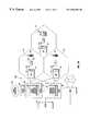
- FIG. 1Aillustrates an embodiment of a mobile communications system that provides both a circuit-switched traffic link and a packet-switched data link.
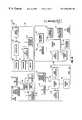
- FIG. 1Bis a block diagram of components in a mobile switching center (MSC), a base station, a data traffic service node, and a mobile unit in the mobile communications system of FIG. 1 A.
- MSCmobile switching center
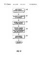
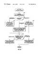
- FIGS. 1C and 1Dare flow diagrams of tasks performed by a data traffic system controller in the data traffic service node of FIG. 1 B.
- FIG. 2illustrates main carriers for use in the mobile communications system of FIG. 1 A.
- FIGS. 3A and 3Billustrate main carriers and secondary carriers in accordance with one embodiment for use in the mobile communications system of FIG. 1 A.
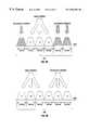
- FIGS. 4, 5 A- 5 C, and 6 A- 6 Cillustrate allocation of secondary carriers to cell sectors in accordance with three different arrangements.
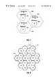
- FIG. 7illustrates a hierarchical cell structure for packet data traffic services in the mobile communications system of FIG. 1 A.
- FIG. 8illustrates a 1/3 channel reuse pattern for packet data traffic communicated over the packet-switched data link in the mobile communications system of FIG. 1 A.
- FIGS. 9 and 10illustrate effective 4/12 and 3/9 channel reuse patterns in accordance with some embodiments that may be employed by the packet-switched data link of the mobile communication system of FIG. 1 A.
- FIG. 11illustrates allocation of a secondary carrier to a high capacity sector in accordance with an example in the mobile communications system of FIG. 1 A.
- FIGS. 12-14illustrate time-division multiple access (TDMA) frames for carrying data traffic and control signaling in accordance with some embodiments in the packet-switched data link of the mobile communications system of FIG. 1 A.
- TDMAtime-division multiple access
- FIG. 15illustrates a 52-frame multiframe for carrying packet data traffic and control signaling in the system of FIG. 1 A.
- FIGS. 16A, 16 B and 17illustrate multiframes in several time groups in accordance with some embodiments for carrying data traffic and control signaling in the packet-switched data link.
- FIG. 18illustrates TDMA frames for carrying data traffic and control signaling in transmit and receive paths of the packet-switched data link.
- FIG. 19illustrates a synchronization burst for use in the packet-switched data link.
- FIGS. 20A, 20 B and 21illustrate multiframes in accordance with further embodiments for use in large cells.
- a mobile communications system 10which may be a cellular or a personal communications services (PCS) system, includes a plurality of cells 14 each having a base station 18 .
- the base station 18is capable of communicating with mobile units 20 (e.g., mobile telephones, mobile computers, or other types of mobile units) over radio frequency (RF) wireless links.
- the base stations 18are controlled by a mobile switching center (MSC) 12 for circuit-switched communications.
- MSCmobile switching center
- the base stations 18are controlled by a data traffic service node 35 .
- groups of base stations 18may be controlled by base station controllers (not shown) that are in turn in communication with the MSC 12 and the data traffic service node 35 .
- the base station 18 and mobile units 20 in each cell 14are capable of communicating over two sets of carriers—a first set of carriers 26 for communicating circuit-switched traffic (e.g., speech data, short messaging services, and other circuit-switched data) and associated control signals; and a second set of carriers 28 (referred to as “packet data carriers”) for communicating packet-switched data traffic and associated control signals.
- circuit-switched trafficis referred to as primary traffic
- packet-switched data trafficis referred to as packet data traffic.
- Packet data trafficmay refer to any traffic that is sent in bursts of messages, packets, or other data units over a link.
- packet data trafficmay be communicated over a data network 32 , which may include private networks 32 (e.g., local area networks or wide area networks) as well as public networks (e.g., the Internet).
- a packet-based networkis one in which the same path may be shared by several nodes.
- IPInternet Protocol
- RFCRequest for Comments
- IPv6IPv6
- a version of IPv6is described in RFC 2460, entitled “Internet Protocol, Version 6 (IPv6) Specification,” dated December 1998.
- the second set of carriers 28 , the base stations 18 , and the data traffic service node 35provide part of the underlying infrastructure for packet-based wireless connections between mobile units 20 and the data network 32 .
- the packet-based wireless networkis an overlay of the primary circuit-switched wireless network.
- the primary circuit-switched systemmay be a time-division multiple access (TDMA) system according to the TIA/EIA-136 protocol from Telecommunications Industry Association).
- TDMAtime-division multiple access
- GSMGlobal System for Mobile
- the packet data traffic services in one embodimentmay be according to the Enhanced General Packet Radio Service (EGPRS) Compact protocol adopted by ETSI (European Telecommunications Standards Institute).
- ETSIEuropean Telecommunications Standards Institute
- other protocols for packet-based servicesmay be employed.
- the number of channels or carriers employed for packet data servicesis generally limited (e.g., the three carriers 28 in one embodiment). Deploying packet data services on the relatively small number of channels may be sufficient for some areas, such as areas having normal or low “bursty” traffic conditions.
- the traffic burstiness of a given areadepends on the amount of call setups (to establish a cell) and terminations (to terminate a call) that occur within the area. The larger the number of call setups and terminations, the more bursty the traffic. In a high bursty environment, more control signal bursts on each carrier may be needed to handle the larger number of call setups and terminations.
- a cell segmentmay include an entire cell, a cell sector, or some other predefined portion of a cell.
- each cell segment in a high bursty regioncan have two groups of packet data carriers 28 , a main group and a secondary group.
- the main group of packet data carriersare used for carrying control and traffic signaling including control signaling involved in selection and reselection of cell segments by a mobile unit, while the secondary group of carriers are used for carrying control signaling and traffic signaling but not control signaling used for selection or reselection.
- Selectionrefers to the procedure for selecting a cell segment from a group of neighboring cell segments when a mobile unit initially starts up, while reselection refers to the procedure for re-selecting a new cell segment in response to movement by the mobile unit between cell segments.
- selectionis intended to encompass either selection or reselection of cell segments.
- the mobile communications system 10may include areas (e.g., high bursty traffic areas) that include cell segments with both main and secondary groups of packet data carriers and other areas including segments with only the main group of packet data carriers.
- the secondary carriersmay also be used to implement a hierarchical cell structure to expand capacity in a cell segment.
- a hierarchical cell structureis a multi-layered cell structure that may be used to accommodate capacity needs, provide segmentation of different types of users, and reduce operational power levels and interference.
- a lower layer of one or more cell segmentsmay operate under the umbrella of a higher layer cell segment.
- the lower layer cell segment(s)may operate at a lower radio frequency (RF) signal power than the radio frequency (RF) signal power of the higher layer cell segment.
- RFradio frequency
- the lower layer cell segmentmay be referred to as microcell segment, while the higher layer cell segment may be referred to as a macrocell segment.
- Lower layers of cell segmentsmay be referred to as picocell segments or other designations.
- the lower layer cell segment(s)may be used to add capacity.
- One examplemay be added capacity to handle the increase in call volume during high usage periods (e.g., during rush hour).
- the macrocell layermay be set to handle traffic during non-peak periods, while one or more microcell layers may be added to handle increases in traffic during high usage periods.
- time delay parametersmay be defined to allow mobile units moving at relatively high speeds (e.g., regular car traffic speeds) to select the macrocell layer and not the microcell layer.
- microcell layerAs the speeds of mobile units slow down during peak usage periods, they will be able to select the microcell layer as well as the macrocell layer.
- Another example of added capacitymay be a microcell segment(s) provided in a shopping center. Geographically, a lower layer cell-segment may have the same coverage area or smaller coverage area than a higher layer cell segment. Other arrangements may have other layering schemes.
- Layeringmay be accomplished by adding secondary carriers to a cell segment.
- a first layer in the cell segmentmay include a main carrier.
- a lower layer in the cell segmentmay include a secondary carrier.
- both main and secondary carrierscarry control signaling used for selection. This is contrasted to the secondary carrier added to a high bursty cell segment, which does not carry control signaling used for selection.
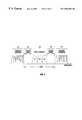
- the base stations 18include transceivers 25 that send and receive 30-kHz (kilohertz) carriers 26 to carry circuit-switched traffic and associated control signals, e.g., according to the TIA/EIA-136 protocol.
- packet data traffic and associated control signalsare carried by 200-kHz packet data carriers 28 , including a main group of three carriers F 1 , F 2 , and F 3 , which may be provided by transceivers 27 in each base station 18 in the same cell as the 30-kHz carriers.
- Guard bands 30are defined between the first set of carriers 26 and the second set of carriers 28 .
- the second set of three 200-kHz carriers 28 and guard bands 30may be deployed in less than approximately 1 MHz (megahertz) of frequency spectrum in one embodiment.
- packet data carriers 28 Aincluding both main and secondary carriers are illustrated.
- the carriers 28 Ainclude main carriers F 1 , F 2 , and F 3 and secondary carriers F 4 , F 5 , and F 6 .
- Primary carriers 26are assigned frequencies on either side of the secondary carriers 28 A.
- each cellmay be divided into three sectors, with each cell sector assigned one of the main carriers F 1 , F 2 , and F 3 .
- an additional one of the secondary carriers F 4 , F 5 , and F 6may be added to each cell sector. Such cell sectors are referred to as high capacity sectors.
- a given groupe.g., a cell
- several arrangements in allocating the secondary carriers to the cell sectorsare possible.
- high bursty traffic conditions or a hierarchical cell structuremay be present in three sectors per group.
- each of the secondary carriers F 4 , F 5 , and F 6is allocated to a corresponding one of the three high capacity sectors.
- two sectors in a groupmay be high capacity sectors.
- two of the secondary carriers F 4 , F 5 , and F 6may be allocated to the two corresponding high capacity sectors.
- one sector per groupmay be a high bursty capacity sector.
- one of the secondary carriers F 4 , F 5 , and F 6may be allocated to the one high capacity sector.
- the secondary carriers F 4 and F 5are assigned frequencies above the frequencies of carriers F 1 , F 2 , and F 3 , while the secondary carrier F 6 is assigned a frequency below the frequency of the F 1 carrier.
- Such an arrangementprovides flexibility in how secondary carriers may be assigned to high capacity sectors without wasting frequency spectrum for guard bands.
- the positions of F 4 , F 5 , and F 6may be swapped, with F 4 and F 5 assigned frequencies below F 1 , and F 6 assigned a frequency above F 3 .
- the secondary carrier F 4is allocated to the same cell sector that is allocated the main carrier F 1
- the secondary carrier F 5is allocated to the cell sector that is allocated the main carrier F 2
- the secondary carrier F 6is allocated to the cell sector that is allocated the main carrier F 3 .
- the main and secondary packet data carriers in each high capacity sectoris separated by the width of two channels. In this arrangement, the spectrum taken up by the main and secondary carriers is about 1.2 MHz plus guard bands.
- the main carrier F 1 , F 2 , or F 3carries control signaling used for selection, while the secondary carrier F 4 , F 5 , or F 6 does not.
- both the main carrier F 1 , F 2 , or F 3 and the secondary carrier F 4 , F 5 , or F 6carry control signaling used for selection.
- the high capacity sectors with main carriers F 1 and F 2(FIG. 5A) or F 2 and F 3 (FIG. 5B) or F 1 and F 3 (FIG. 5C) are allocated secondary carriers F 4 and F 5 .
- the two high capacity sectors having main carriers F 1 and F 2are allocated secondary carriers F 4 and F 5 , respectively.
- the two high capacity sectors having main carriers F 2 and F 3may be allocated the secondary carriers F 4 and F 5 , respectively.
- FIG. 5Athe high capacity sectors having main carriers F 1 and F 2
- F 2 and F 3may be allocated the secondary carriers F 4 and F 5 , respectively.
- the two high capacity sectors having main carriers F 1 and F 3may be allocated secondary carriers F 4 and F 5 , respectively.
- the main and secondary packet data carriers in each high capacity sector in FIGS. 5A-5Care separated by the width of at least one channel. In this arrangement, the spectrum used is about 1 MHz plus guard bands.
- a high capacity sector with the main carrier F 1 (FIG. 6A) or F 2 (FIG. 6B)is allocated the secondary carrier F 4 .
- a high capacity sector with the main carrier F 3 (FIG. 6C)is allocated the secondary carrier F 6 .
- the spectrum usedis about 0.8 MHz plus guard bands.
- the main carrier and secondary carrierare separated by at least the width of one carrier (200 kHz in one embodiment) to avoid adjacent carrier interference.
- guard bands between the main and secondary carriers in a high capacity sectorcan be avoided to improve spectral efficiency.
- the secondary carrier F 6may be allocated to the sector having the main carrier F 3 .
- the secondary carrier F 4may be allocated to the sector having the main carrier F 1 .
- the secondary carrier F 6is not assigned below F 1 , but instead all three secondary carriers are assigned frequencies above that of the main carrier F 3 , then some frequency spectrum may be wasted to provide the necessary guard band to avoid adjacent channel interference in allocating a secondary carrier to a high capacity sector with the main carrier F 3 .
- F 5may have to be used, which wastes the channel width associated with the carrier F 4 .
- the same spectral efficiencymay be achieved with any other frequency allocation scheme in which at least one of the secondary carriers is placed on the other side of the group of main carriers with respect to the remaining secondary carriers.
- the secondary carriers F 4 , F 5 , and F 6may be assigned in sequence above or below the main carriers F 1 , F 2 , and F 3 , as illustrated in FIG. 3B, which shows a sequence of packet data carriers 28 B.
- the main and secondary carriers F 1 -F 6may be intermingled.
- Each cell sectorincludes multiple layers, with the upper layer referred to as a macrocell sector ( 240 , 242 , or 244 ) and the lower layer referred to as a microcell sector ( 246 , 248 or 250 ).
- the macrocell sectors 240 , 242 and 244are associated with main carriers F 1 , F 2 and F 3 , respectively.
- the microcell sectors 246 , 248 and 250are associated with secondary carriers F 4 , F 5 and F 6 , respectively.
- cell sectorsthat are assigned one main carrier and one secondary carrier
- other embodimentsmay have cell sectors with a plurality of main carriers and one or more secondary carriers.
- the MSC 12includes a primary traffic system controller 42 that controls the establishment, processing, and termination of circuit-switched calls (e.g., speech, short messages, and so forth) between or among mobile units 20 in one or more cells 14 or between or among mobile units 20 in a cell 14 and a wireline device (e.g., a telephone) coupled to a public switched telephone network (PSTN) 16 .
- a wireline devicee.g., a telephone
- PSTNpublic switched telephone network
- More than one MSCsuch as an MSC 34 associated with a different cellular service provider
- Other data traffic service nodesmay also be present to provide access to the data network 32 for other mobile units.
- the data traffic service node 35includes a data traffic system controller 40 that controls the establishment, processing, and termination of packet-switched communications.
- the data traffic service node 35may be a serving GPRS support node (SGSN) according to the General Packet Radio Service (GPRS) protocol.
- SGSNserving GPRS support node
- GPRSGeneral Packet Radio Service
- the SGSN 35communicates with a gateway GPRS support node (GGSN) 36 , which provides an interface to a data network 32 .
- GGSNgateway GPRS support node
- the nodes 35 and 36may include any system or systems that are capable of controlling packet-switched data communications between a mobile unit 20 and the data network 32 .
- the nodes 35 and 36may be implemented in the same platform as the MSC 12 in an alternative embodiment.
- two wireless linksare provided for mobile units 20 in the cells 14 controlled by the MSC 12 : a packet data link, including the carriers 28 , the base stations 18 , and the data traffic system controller 40 , to provide relatively high-speed (up to 384 kbps or higher, for example) packet-switched communications between mobile units 20 and the data network 32 ; and a primary traffic link, including the carriers 26 , the base stations 18 , and the primary traffic system controller 42 to provide speech and other circuit-switched communications between mobile units 20 or between a mobile unit 20 and a PSTN unit.
- the primary traffic system controller 42controls communications according to the TIA/EIA-136 protocol. In another example, the primary traffic system controller 42 may control communications according to the GSM protocol, which uses 200-kHz carriers, instead of 30-kHz carriers, to carry primary traffic.
- GSMGlobal System for Mobile Communications
- TDMA framesmay be used to carry traffic and control signals.
- a frame according to TIA/EIA-136includes six time slots, while a frame according to GSM includes eight time slots.
- framesare also defined to carry data traffic and associated control signals.
- the frame for the packet data linkmay be similar to a GSM frame with eight time slots (also referred to as burst periods) TN 0 -TN 7 (described further below in connection with FIGS. 12 - 14 ).
- the data traffic system controller 40 and the primary traffic system controller 42may be implemented in separate platforms (the data traffic service node 35 and the MSC 12 , respectively). In an alternative embodiment, the system controllers 40 and 42 may be implemented in the same platform. Similarly, transceivers for sending and receiving carriers 26 and 28 may be included in the same base station 18 or in separate base stations.
- each cellmay be divided into three sectors.
- the primary traffic linkmay utilize a 7/21 channel reuse pattern, as an example.
- the frequency reuse distance D for a 7/21 channel reuse patternis large enough such that the C/I (carrier-to-interference) performance of control channels on the primary traffic link is robust.
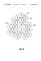
- each base station siteis allocated one of three main carrier frequencies F 1 , F 2 , and F 3 (see also FIG. 2 ), one per sector, using a 1/3 frequency reuse pattern for data traffic, as illustrated in the tricellular representation of FIG. 8 .
- an equivalent trisector representationmay also be used to show the cellular arrangement of FIG. 8 .
- the one or more sectors in the clustermay also contain secondary carriers F 4 -F 6 , if they are needed for high bursty sectors or for creation of a hierarchical cell structure.
- Data trafficmay also be carried by the secondary carriers using the 1/3 frequency reuse pattern.
- One main carrier(and perhaps one secondary carrier) is allocated per sector of each cell 14 .
- Data traffic in the packet data linkmay employ various mechanisms, including link adaptation and incremental redundancy, to provide more robust C/I performance in a 1/3 channel reuse pattern.
- the 1/3 channel reuse patternis vulnerable to interference because the same frequencies are reused within relatively small distances of each other.
- a channel reuse plan that employs a small number of channelsmay cause interference problems due to relatively small distances between cells or cell sectors having the same frequency.
- a higher effective channel reuse planis created by assigning cells or cell sectors to different combinations of frequencies and time.
- a higher effective channel reuse patternthat is based on both frequency and time can be achieved as compared to a reuse plan based only on the available frequencies, such as performed in conventional mobile systems.
- the higher effective channel reuse patterne.g., 3/9, 4/12, and other patterns, may be employed in accordance with some embodiments to provide more robust C/I performance.
- control signal burstsmay be staggered in time to provide both frequency separation and time separation for higher effective channel reuse patterns.
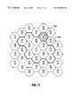
- an effective 4/12 channel reuse patternis illustrated for a cluster of cell sectors that include main carriers F 1 -F 3 but not secondary carriers F 4 -F 6 .
- the effective 4/12 patternfour time groups (T 1 -T 4 ) are created.
- the reuse patternalso has an orthogonal aspect based on time (T 1 -T 4 ).
- each sectoris assigned a frequency Fx as well as a time group Ty.
- a cluster 100 of 12 sectorscan be defined.
- the cluster 100is then repeated to provide the effective 4/12 channel reuse pattern.
- time reuse that is added on top of frequency reusecreates a higher effective channel reuse pattern for control channels on the packet data link, thereby creating more robust performance with reduced interference problems.
- a sector having a certain frequency Fx in time group Tyis separated by some distance from another sector having the same frequency Fx and being in the same time group Ty (generally the distance provided by the width and length of each cluster 100 ).
- the sectors 102 having frequency F 1 and belonging to time group T 4are separated by relatively large distances from each other to reduce the likelihood of interference.
- Another advantage offered by the effective 4/12 channel reuse pattern as illustrated in FIG. 9is that adjacent channel interference is reduced between the main F 1 and F 2 carriers and the main F 2 and F 3 carriers.
- the sector 102is associated with F 1 and T 4 .
- the sectors adjacent the sector 102are in one of time groups T 1 -T 3 but not T 4 . Since adjacent sectors are communicating control channels in different time periods, interference between adjacent main carriers (F 1 , F 2 , F 3 ) is reduced.
- guard bandsdo not need to be defined between the main carriers F 1 , F 2 , and F 3 , which allows for reduced frequency spectrum allocation for carriers used to communicate packet data.
- an effective 3/9 reuse patternis illustrated for a cluster 101 including sectors having main carriers F 1 -F 3 but not secondary carriers F 4 -F 6 .
- the effective 3/9 reuse patternutilizes three time group T 1 , T 2 and T 3 . This effectively provides a cluster 101 of nine sectors in which each sector has a distinct combination of a frequency Fx and time group Ty.
- the effective 3/9 reuse patternthe reduced adjacent channel interference feature as offered by the effective 4/12 reuse pattern is not available.
- guard bands between the carriersmay need to be defined.
- a cluster 140has an effective 4/12 channel reuse pattern, similar to the one described in connection with FIG. 9 .
- the cluster 140also includes a high capacity sector 130 , which is the shaded sector.
- the high capacity sector 130is assigned the main frequency F 1 and is in time group T 4 .
- it is desired to add a secondary carrier to the high capacity sector 130which may be the secondary carrier F 4 (see FIG. 3 A).
- the secondary carrier F 4see FIG. 3 A.
- additional high capacity sectorsmay be present in the cluster 140 .
- the higher effective channel reuse patternsmay be employed for both main and secondary packet data carriers.
- the base stations 18are time synchronized with each other. This may be performed by using a global positioning system (GPS) timing receiver or some other synchronization circuit 19 (FIG. 1A) in each base station 18 . Synchronization of the base station 18 is employed to ensure alignment of the time groups in the cell sectors. Base station synchronization is carried out such that the following two criteria are satisfied. TDMA frames (including time slots TN 0 -TN 7 ) of the packet data link are aligned with each other in all sectors.
- GPSglobal positioning system
- FOG. 1Asome other synchronization circuit 19
- time slot TN 0occurs at the same time at each base station site in each sector, to within tolerances of the synchronization equipment and any differences in propagation delays.
- the control and traffic channels of the data linkare carried by a multiframe structure (discussed further below in connection with FIGS. 15 - 17 ).
- Each multiframe structurestarts with frame 0 and continues to frame NN (e.g., 50 or 51 ).
- frame NNe.g., 50 or 51
- frame 0occurs at the same time in each sector.
- the primary traffic transceiver 25 and packet data traffic transceiver 27are connected to an antenna tower 54 that transmits and receives the first and second sets of carriers 26 and 28 .
- the primary traffic and packet data traffic transceivers 25 and 27are connected to a control unit 50 , on which various software routines 49 may be executable.
- a storage unit 47may also be connected to the control unit 50 .
- Also connected to the control unit 50is a GPS timing receiver or other synchronization circuit 19 that allows synchronization of all base stations in the group of cells 14 controlled by the MSC 12 and data traffic service node 35 .
- the base station 18includes an MSC interface 52 that is coupled to a link 64 (e.g., a T 1 link) that is in turn coupled to an interface unit 56 in the MSC 12 .
- the base station 18also includes an interface 51 (which in one embodiment is a G b interface 51 according to GPRS) for communicating over a link (e.g., a G b link) to the data traffic service node 35 .
- a control unit 58provides the processing core of the MSC 12 .
- the control unit 58may be implemented with computer systems, processors, and other control devices.
- the control unit 58is connected to a storage unit 62 , which may contain one or more machine-readable storage media to store various data as well as instructions of software routines or modules that are loadable for execution by the control unit 58 .
- routines or modules that make up the primary traffic system controller 42may be stored in the storage unit 62 and loaded for execution by the control unit 58 .
- the MSC 12may also include a PSTN interface 60 that is coupled to the PSTN 16 to allow communications with a PSTN-connected unit.
- the MSC 12includes an interface 75 (e.g., a G s interface) for communicating over a link (e.g., a G s link) to the data traffic service node 35 .
- the data traffic service node 35includes interface units 77 and 79 for communicating over the G b and G s links, respectively, in one embodiment.
- the processing core of the data traffic service node 35includes a control unit 69 , which may be implemented with computer systems, processors, or other control devices.
- a storage unit 71 including machine-readable storage mediais coupled to the control unit 69 . Instructions associated with the routines and modules that make up the data traffic system controller 40 may be initially stored in the storage unit 71 and loaded by the control unit 69 for execution.
- the data traffic service node 35further includes an interface 81 (e.g., a G n interface) for communicating with the GGSN 36 (FIG. 1 A).
- the interface 81may be a network interface controller or other transceiver capable of communicating over the data network 32 .
- the data traffic and primary traffic system controllers 40 and 42may be implemented in one platform and executable by the same control unit.
- Carriersare communicated between the antennas 54 coupled to the base station 18 and an antenna 62 of a mobile unit 20 .
- one or more radio transceivers 64are connected to the antenna 62 to send and receive packet data carriers and primary traffic carriers.
- a control unit 66(or one or more other suitable control devices) may be coupled to the one or more radio transceivers 64 .
- the control unit 66is coupled to a storage unit 68 , which may be in the form of a non-volatile memory (such as a flash memory or an electrically erasable and programmable read-only memory) and/or dynamic and static random access memories (DRAMs and SRAMs).
- a non-volatile memorysuch as a flash memory or an electrically erasable and programmable read-only memory
- DRAMs and SRAMsdynamic and static random access memories
- Instructions of software routines 68 executable on the control unit 66may be initially stored in a non-volatile portion of the storage unit 68 .
- An input/output (I/O) controller 74is coupled to the keyboard 70 and display 72 of the mobile unit 20 .
- Control unitsmay include microprocessors, microcontrollers, processor cards (including one or more microprocessors or microcontrollers), or other control or computing devices.
- the instructions of such software routines or modulesmay be stored in respective storage units each including one or more machine-readable storage media.
- the storage mediamay include different forms of memory including semiconductor memory devices such as dynamic or static random access memories (DRAMs or SRAMs), erasable and programmable read-only memories (EPROMs), electrically erasable and programmable read-only memories (EEPROMs) and flash memories; magnetic disks such as fixed, floppy and removable disks; other magnetic media including tape; and optical media such as compact discs (CDs) or digital video discs (DVDs).
- DRAMs or SRAMsdynamic or static random access memories
- EPROMserasable and programmable read-only memories
- EEPROMselectrically erasable and programmable read-only memories
- flash memoriessuch as fixed, floppy and removable disks
- magnetic mediasuch as fixed, floppy and removable disks
- optical mediasuch as compact discs (CDs) or digital video discs (DVDs).
- CDscompact discs
- DVDsdigital video discs
- the instructions of the software routines or modulesmay be loaded or transported into each respective system in one of many different ways. For example, code segments or instructions stored on floppy disks, CD or DVD media, a hard disk, or transported through a network interface card, a modem, or other interface device may be loaded into the system and executed as corresponding software routines or modules.
- data signalsthat are embodied as carrier waves (transmitted over telephone lines, network lines, wireless links, cables, and the like) may communicate the code segments or instructions to the respective system or device.
- carrier wavesmay be in the form of electrical, optical, acoustical, electromagnetic, or other types of signals.
- the data traffic system controller 40allocates (at 80 ) a predetermined number of channels. In one embodiment, three main carriers having frequencies F 1 , F 2 , and F 3 are allocated one to each sector of each cell 14 .
- the data traffic system controller 40defines (at 82 ) a plurality of time groups. In one embodiment, three time groups T 1 , T 2 , and T 3 may be defined. In another embodiment, four time groups T 1 , T 2 , T 3 , and T 4 may be defined.
- the data traffic system controller 40Based on the carrier frequencies F 1 -F 3 and time groups T 1 -T 3 or T 1 -T 4 , the data traffic system controller 40 provides (at 84 ) a channel reuse pattern for communications over the packet data link. Further, based on synchronization information received by the synchronization circuit 19 (which may include a GPS timing receiver), the data traffic system controller 40 may synchronize (at 86 ) the timings of signal transmissions and receptions of control signaling in base station 18 in all the cells 14 so that they are aligned in time.
- the synchronization circuit 19which may include a GPS timing receiver
- a secondary carriermay be allocated by the data traffic system controller 40 in the data traffic service node of 35 .
- the data traffic system controller 40first determines (at 260 ) the main carrier frequency of the given cell sector.
- the system controller 40determines (at 262 ) which of the three arrangements is implemented: arrangement 1 (three high capacity sectors are present in one cell); arrangement 2 (two high capacity sectors are present in one cell); and arrangement 3 (one high capacity sector is present in one cell).
- the secondary carrier F 4is allocated (at 264 ) to the cell sector with the main carrier F 1 , the secondary carrier F 5 is allocated to the cell sector with the main carrier F 2 , and the secondary carrier F 6 is allocated to the cell sector with the main carrier F 3 .
- carriers F 4 and F 5are allocated (at 266 ) to cell sectors having one of the following three groups of main carriers: F 1 and F 2 , F 1 and F 3 , and F 2 and F 3 .
- the system controller 40allocates (at 268 ) the secondary carrier F 4 to a cell sector having a main carrier F 1 or F 2 , or alternatively, the system controller 40 allocates the secondary carrier F 6 to a cell sector having main carrier F 3 .
- the system controller 40determines (at 270 ) if the high capacity sector is one having a high bursty condition or one with a hierarchical cell structure. If the high capacity cell sector is a high bursty cell sector, then communication of control signaling for selection and reselection on the secondary carrier is disabled (at 272 ). However, if the high capacity sector includes a hierarchical cell structure, then communication of the selection and reselection signaling is enabled (at 274 ) on the secondary carrier.
- the control channels employed in the packet data linkinclude packet broadcast control channels (PBCCH), packet common control channels (PCCCH), and packet data traffic channels (PDTCH).
- the broadcast control channels PBCCHcommunicated downlink (from base station to mobile unit), provide general information on a per base station basis (e.g., cell/sector specific information) including information employed for mobile units 20 to register in the system 10 .
- the common control channels PCCCHcarry signaling information used for access management tasks (e.g., allocation of dedicated control channels and traffic channels).
- PCCCHincludes a packet paging channel (PPCH) and a packet access grant channel (PAGCH) for downlink communications
- PCCCHincludes a packet random access channel (PRACH) for uplink communications (mobile unit to base station).
- PPCHpacket paging channel
- PAGCHpacket access grant channel
- PRACHpacket random access channel
- PRACHis used by a mobile unit 20 to request access to the system 10 .
- PPCHis used by the base station 18 to alert a mobile unit 20 of an incoming call.
- PAGCHis used to allocate a channel to a mobile unit 20 for signaling to obtain a dedicated channel following a request by the mobile unit 20 on PRACH.
- Other control channelsinclude a packet frequency correction channel (PFCCH) and a packet synchronization channel (PSCH).
- PFCCH and PSCHare used to synchronize a mobile unit 20 to the time slot structure of each cell by defining the boundaries of burst periods and time slot numbering.
- PSCHis used for selection while PFCCH is used for reselection.
- the control channels discussed abovemay be extensions of circuit-switched logical channels used in a GSM system.
- the control channels that are communicated with the higher effective 3/9, 4/12, or other channel reuse patterninclude PBCCH, PCCCH, PFCCH, and PSCH.
- the data traffic channels PDTCH and associated traffic control channels, PTCCH (packet timing advance control channel) and PACCH (packet associated control channels)use the 1/3 reuse pattern, since traffic channels employ various mechanisms, as noted above, to better withstand interference from neighboring cell segments.
- each main or secondary carrier (F 1 , F 2 , F 3 , F 4 , F 5 , or F 6 ) in the packet data linkcarries a TDMA frame 110 that is divided into a plurality of time slots.
- a TDMA frame 110is structured like a GSM frame and has a length of 120/26 ms (or about 4.615 ms). To provide an effective 4/12 reuse pattern, control channels are staggered across four different time groups.
- control channels(PBCCH, PCCCH, PFCCH, and PSCH in one embodiment) are transmitted during time slot TN 1 ; in time group 2 , control channels are transmitted in time slot TN 3 ; in time group 3 , control channels are transmitted during time slot TN 5 ; and in time group 4 , control channels are transmitted during time slot TN 7 .
- a channel reuse patternmay be divided according to both frequency and time. More generally, in each time group, control signaling may be carried in at least one time slot (less than all the time slots) provided that different sub-groups of time slots are used in different time groups.
- a blockincludes four frames of a multiframe (e.g., a 51- or 52-frame multiframe).
- the control channelsare placed in time slot TN 1 (in time group T 1 ), time slot TN 3 (in time group T 2 ), and time slot TN 5 (in time group T 3 ).
- the time slots that carry control channelsare indicated as being C time slots. Also illustrated in FIG. 13 are T time slots (during which packet data traffic may be transmitted) and I time slots (which are idle during blocks that transmit PBCCH or PCCCH in other time groups but which carry packet data traffic otherwise).
- control channelsmay be carried in time slots other than TN 1 , TN 3 , TN 5 or TN 7 (FIG. 12) or TN 1 , TN 3 , or TN 5 (FIG. 13 ).
- the control channelsinstead of placing control channels in odd time slots TN 1 , 3 , 5 and 7 , the control channels may be placed in time slots TN 0 , TN 2 , TN 4 , and TN 6 in the different time groups.
- Other staggering schemesmay also be employed, with some control channels communicated in even time slots and others communicated in odd time slots, for example. Referring to the example of FIG.
- control channelsmay be placed in the C time slots: time slot TN 0 in time group 1 , time slot TN 2 in time group 2 , and time slot TN 4 in time group 3 .
- the T time slotscarry data traffic
- the I time slotsare idle during blocks that transmit PBCCH or PCCCH in other time groups but carry packet data traffic otherwise.
- other staggering schemescan be provided to provide fewer or larger numbers of time groups.
- Each base station 18 and mobile unit 20uses a time group number (TG) to indicate the time group the base station 18 and mobile unit 20 is in.
- the TG numbermay be carried in the PSCH and PFCCH bursts.
- time slots TN 1 , 3 , 5 , and 7correspond to time groups 1 , 2 , 3 , and 4
- the following values of TGindicate the time slot to be used for carrying control channels.
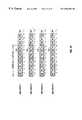
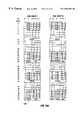
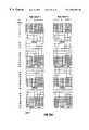
- FIGS. 15-17communication using 52-frame multiframes 120 in accordance with some embodiments is illustrated.
- the structure of a multiframe 120is illustrated in FIG. 15 .
- Each multiframe 120includes 52 TDMA frames (FRN 0 - 51 ), which are divided into 12 blocks B 0 -B 11 , leaving four frames FRN 12 , 25 , 38 , and 51 to carry predetermined channels.
- other multiframe structuresmay be used, such as a 51-frame multiframe.
- the eight columns of the multiframe 120correspond to the eight time slots TN 0 -TN 7
- the 52 rowscorrespond to the 52 frames of the multiframe 120 .
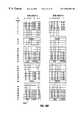
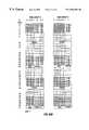
- FIGS. 16A and 16Billustrate a multiframe structure 120 A employing an effective 4/12 reuse pattern
- FIG. 17illustrates a multiframe structure 120 B employing an effective 3/9 reuse pattern.
- FIGS. 16A, 16 B, and 17three blocks of each multiframe are assigned to PCCCH (frames containing a C) and one block is assigned to PBCCH (frames containing a B).
- a blockincludes four TDMA frames.
- the number of blocks allocated for PBCCH and PCCCHis flexible, from two up to 12 blocks per time slot in each multiframe 120 .
- PBCCHis carried in block B 0
- PCCCHis carried in blocks B 5 , B 8 , and B 11 .
- Frames FRN 25 and 51carry PFCCH and PSCH, respectively, and frames FRN 12 and 38 carry PTCCH.
- Frames marked with an “X”are idle, and correspond to the odd time slots (TN 1 , TN 3 , TN 5 , or TN 7 ) in blocks ( 0 , 5 , 8 , and 11 ) that carry control channels PBCCH and PCCCH in other time groups.
- the frames in block B 0 in time slot TN 3 in each of time groups 1 , 3 , and 4are idle because the frames in time slot TN 3 of time group 2 carries PBCCH.
- frames in blocks B 5 , B 8 , and B 11 in time slots TN 1 , 3 , 5 , or 7that do not carry control signaling.
- the illustrated multiframes 120 A and 120 Bmay be the multiframes carried on the main carrier (F 1 , F 2 , or F 3 ) of a high bursty sector.
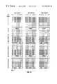
- the PBCCH, PCCCH, and PTCCHmay be assigned to the same frames.
- the same number of PCCCH framesmay be present in the multiframes carried by the main and secondary carriers.
- a multiframe carried by a secondary carrier in a high bursty sectordoes not contain PSCH and PFCCH, which are used for selection and reselection, respectively. However, in a hierarchical cell sector, both the main and secondary carriers carry PSCH and PFCCH in respective multi frames.
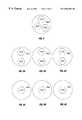
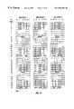
- a measurement windowis defined during which a mobile unit 20 can measure either PSCH (for cell sector selection) or PFCCH (for cell sector re-selection).
- the measurement window in this exampleis for a mobile unit that is active on time slot TN 0 . With other arrangements, the measurement window begins and ends at different time slots.
- time slot TN 1may be the one used to carry PSCH or PFCCH.
- time slot TN 0 and TN 2 -TN 7are idle in frame FRN 25 (which carries PFCCH) and frame FRN 51 (which carries PSCH).
- a first mobile unitcan measure PSCH or PFCCH (on the downlink path) in time slot TN 1 (if time group T 1 has been selected, based on the value of TG).
- a second mobile unitin a neighboring cell sector
- Transmission of such traffic in TN 6 by the second mobile unitmay interfere with the measurement of PSCH or PFCCH by the first mobile unit.
- the mobile unitmay not be able to “see” all time groups due to such interference.
- a time group rotation schememay be employed, in which the value of TG is rotated through 0 , 1 , 2 , and 3 at predetermined time points.
- the time group used for carrying control channelsmay be rotated in any given cell sector.
- Rotation of time groupsoccur concurrently in all the base station sites so that division of time groups among the sectors is maintained. Rotation may be accomplished by updating the value of TG with each new occurrence of a multiframe.
- the value of TGmay be rotated with each increment of a predetermined parameter MFN, which represents the multiframe number that ranges between zero and three.
- MFNis calculated from the TDMA frame number FRN according to the following:
- MFN( FRN ⁇ 52) mod 4.
- the value of TGis rotated to rotate the time group assigned to each cell sector.
- the time group rotationmay occur between frame numbers (FRN) mode 52 equal to 3 and 4.
- the time group rotation for the secondary carriersare synchronized with the group rotation for the main carriers.
- a mobile communications systemhas been described that allows for expanded carrier capacity by use of secondary carriers.
- the secondary carriersmay be allocated to sectors in which high bursty conditions are present to enable the addition of control bursts, such as PCCCH bursts, to handle the added call setup and termination load.
- control burstssuch as PCCCH bursts
- additional layersmay be added to predetermined sectors.
- a hierarchical cell structureallows a cell sector to handle increased capacity during high usage periods. Further, a hierarchical cell structure allows for the segregation of different groups of users.
- a mobile unit 20monitors signal strengths of control signals from a group of neighboring cell sectors to select or reselect the cell sector providing the strongest signal strength.
- the mobile unit 20may be located closer to a first base station 18 than a neighboring base station 18 , propagation delays due to distances involved in relatively large cells can cause overlap of packet data traffic and control signals in different time slots of the first and neighboring base stations, which may violate the requirement that the time slots be aligned due to inter-base station synchronization.
- predetermined time slotsare employed for carrying control channels, including PSCH and PFCCH, which are used to perform cell selection and reselection.
- control channelsincluding PSCH and PFCCH
- the guard period between packet data traffic channels and the control channelsmay be increased to provide superior protection in relatively large cells.
- a mobile unit 20moves in a cell sector or between cell sectors, it continues to monitor PSCH and PFCCH from neighboring cell sectors to allow the mobile unit 20 to select or reselect the strongest signal.
- the mobile unit 20accomplishes this by measuring the PSCH and PFCCH bursts during predetermined frames. The measurement is made during the mobile unit's data measurement period (also referred to as the measurement window) of all neighboring cells.
- the frequency reuse distance D R for a cellcan be expressed as
- Nis the frequency reuse pattern and R is the cell radius.
- D Ris 1.73R.
- a PSCH burstis illustrated.
- the PSCH burstis 148 bits long plus a guard period (GP) of 8.25 bits (symbols).
- the PFCCH burstalso has the same length as the PSCH burst and is also associated with a guard period of 8.25 bits.
- Other control channel bursts including PBCCH and PCCCHhave the same length and guard period.
- the internal structures of PFCCH, PBCCH, and PCCCHdiffer from that of PSCH as illustrated in FIG. 19 .
- the guard period (GP)is about 30.44 ⁇ sec in length. This translates into approximately 9 kilometers (km).
- D Ris equal to about 9 km
- the estimated maximum cell sizeis approximately 5 km, much less than cell sizes supported by GSM or TIA/EIA-136.
- a large cellmay be defined as a cell of greater than approximately 5 km (the maximum cell size supported). In further embodiments, a large cell may be defined to be larger than other predetermined sizes.
- each cell 14includes three sectors that have been divided into three separate time groups as well as three separate frequencies.
- control channelsare carried in time slots TN 0 , TN 2 , and TN 4 , respectively, of each TDMA frame.
- FIG. 14illustrates placement of control channels including the PSCH and PFCCH bursts in time slots TN 0 , TN 2 and TN 4 in an effective 3/9 channel reuse pattern.
- time slot TN 7(indicated as 212 , 216 , and 218 ).
- time slot TN 0(indicated as 214 ) carries control channels, including the PSCH and PFCCH bursts (in respective frames of the multiframe structure).
- a sector 210is in a cell that has a neighboring cell with sectors 220 and 222 that are both allocated frequency F 1 .
- the sectors 210 , 220 , and 222are in different time groups, with control channels being in time slot TN 0 in the sector 210 , time slot TN 2 in the sector 220 , and time slot TN 4 in the sector 222 .
- a mobile unit 20 in the sector 210may be measuring PSCH bursts in time slot 214 (TN 0 ).
- the packet data trafficbeing transmitted in time slot 216 (TN 7 ) of sector 220 or time slot 218 (TN 7 ) of sector 222 may start to slide into time slot TN 0 of sector 210 .
- the packet data traffic in TN 7is being communicated in the previous frame.
- control channelsmay be placed on odd time slots instead of even slots.
- the control channelsmay be placed on time slots TN 1 , TN 3 , TN 5 for an effective 3/9 channel reuse and on time slots TN 1 , TN 3 , TN 5 and TN 7 for an effective 4/12 channel reuse.
- a larger effective guard periodcan be provided.
- the entire time slot TN 0can be used as a guard period to provide an effective guard period of 8.25 bits (GP from TN 7 in the previous frame) plus 156.25 bits (period of TN 0 plus GP).
- the maximum cell size supported by GSM(35 km) can be supported for high speed packet data transfers over the packet data link.
- odd time slotsmay be used to carry control signals to provide for an increased guard period between packet data traffic and control signaling to maintain base station synchronization in large cells and therefore higher effective reuse patterns (e.g., 3/9, 4/12, and so forth).
- Another concern in a system with relatively large cell sizesis the overlap of data traffic on PDTCH with PBCCH, PCCCH, and other control channels.
- data trafficmay be carried in the time slots ( 0 , 2 , 4 , and 6 ) adjacent the odd time slots carrying PBCCH and PCCCH.
- data trafficmay be carried in time slots ( 0 , 2 , 4 , 6 , and 7 ). With larger cells, overlap of time slots may cause interference of the data traffic and control signaling.
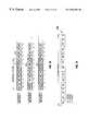
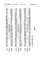
- packet data trafficis removed from blocks carrying control channels PBCCH and PCCCH (e.g., B 0 , B 5 , B 8 and B 11 ) in time slots TN 0 , TN 2 and TN 4 in every sector for an effective 3/9 reuse pattern.
- Packet data trafficis removed from blocks carrying PBCCH and PCCCH on time slots TN 0 , TN 2 , TN 4 , and TN 6 for an effective 4/12 reuse pattern. This is illustrated in FIGS. 20A, 20 B, and 21 , which show multiframes 120 C and 120 D for effective 4/12 and 3/9 channel reuse patterns, respectively, for use in large cells.
- blocks carrying PBCCH and PCCCHdo not carry packet data traffic for large cells in the 4/12 multiframe structure 120 C.
- time slots TN 6 and TN 7 in the blocks carrying PBCCH and PCCCHare allowed to carry packet data traffic, but blocks in time slots not carrying PBCCH or PCCCH are idle.
- a guard period greater than a time slot periodis provided to protect PBCCH and PCCCH.
- control channelssuch as PTCCH
- block B 2 before frame FRN 12 carrying the first PTCCHmay be set idle to protect PTCCH in frame number 12 of time slot TN 0 . Similar protection may be afforded PTCCH in frame FRN 38 if PCCCH in block 8 is moved elsewhere.
Landscapes
- Engineering & Computer Science (AREA)
- Computer Networks & Wireless Communication (AREA)
- Signal Processing (AREA)
- Mobile Radio Communication Systems (AREA)
Abstract
Description
| TN | |||
| 0 | 1 | ||
| 1 | 3 | ||
| 2 | 5 | ||
| 3 | 7 | ||
Claims (11)
Priority Applications (5)
| Application Number | Priority Date | Filing Date | Title |
|---|---|---|---|
| US09/435,523US6584084B1 (en) | 1999-03-01 | 1999-11-08 | Expanded carrier capacity in a mobile communications system |
| EP00944907AEP1197112A1 (en) | 1999-06-28 | 2000-06-27 | Method for expanding channel capacity in a mobile communication system |
| PCT/US2000/017620WO2001001721A1 (en) | 1999-06-28 | 2000-06-27 | Method for expanding channel capacity in a mobile communications system |
| AU58932/00AAU5893200A (en) | 1999-06-28 | 2000-06-27 | Method for expanding channel capacity in a mobile communications system |
| CNB008094861ACN1139295C (en) | 1999-06-28 | 2000-06-27 | Method for expanding channel capacity in mobile communications system |
Applications Claiming Priority (6)
| Application Number | Priority Date | Filing Date | Title |
|---|---|---|---|
| US12245999P | 1999-03-01 | 1999-03-01 | |
| US14132799P | 1999-06-28 | 1999-06-28 | |
| US09/368,591US6497599B1 (en) | 1999-03-01 | 1999-08-04 | Channel reuse patterns in a mobile communications system |
| US09/366,849US6944146B1 (en) | 1999-03-01 | 1999-08-04 | Communications of signaling in a mobile communications system with reduced interference |
| US09/368,217US6594252B1 (en) | 1999-03-01 | 1999-08-04 | Locating control signals in a mobile communications system |
| US09/435,523US6584084B1 (en) | 1999-03-01 | 1999-11-08 | Expanded carrier capacity in a mobile communications system |
Related Parent Applications (1)
| Application Number | Title | Priority Date | Filing Date |
|---|---|---|---|
| US09/368,217Continuation-In-PartUS6594252B1 (en) | 1999-03-01 | 1999-08-04 | Locating control signals in a mobile communications system |
Publications (1)
| Publication Number | Publication Date |
|---|---|
| US6584084B1true US6584084B1 (en) | 2003-06-24 |
Family
ID=26838996
Family Applications (1)
| Application Number | Title | Priority Date | Filing Date |
|---|---|---|---|
| US09/435,523Expired - LifetimeUS6584084B1 (en) | 1999-03-01 | 1999-11-08 | Expanded carrier capacity in a mobile communications system |
Country Status (5)
| Country | Link |
|---|---|
| US (1) | US6584084B1 (en) |
| EP (1) | EP1197112A1 (en) |
| CN (1) | CN1139295C (en) |
| AU (1) | AU5893200A (en) |
| WO (1) | WO2001001721A1 (en) |
Cited By (180)
| Publication number | Priority date | Publication date | Assignee | Title |
|---|---|---|---|---|
| US20010022791A1 (en)* | 2000-03-17 | 2001-09-20 | Ouelid Abdesselem | Radio communication system |
| US20010030949A1 (en)* | 2000-02-22 | 2001-10-18 | Johan Molno | Method and apparatus for associated signaling in a wireless communications network |
| US20030125025A1 (en)* | 2001-12-27 | 2003-07-03 | Samsung Electronics Co., Ltd. | System and method for providing concurrent data transmissions in a wireless communication network |
| US20030129985A1 (en)* | 2001-10-26 | 2003-07-10 | Naden James M. | Wireless communications system and method |
| US20030220112A1 (en)* | 2002-01-16 | 2003-11-27 | Engim, Incorporated | System and method for enabling the use of spatially distributed multichannel wireless access points/base stations |
| US20040214579A1 (en)* | 2003-04-24 | 2004-10-28 | Nokia Corporation | Dynamic coverage and capacity solution for cellular radio network |
| US7145896B1 (en)* | 1999-10-15 | 2006-12-05 | Nokia Corporation | Method for transmitting data on a packet data channel |
| CN100369388C (en)* | 2004-12-29 | 2008-02-13 | 中兴通讯股份有限公司 | Method for variable distributing power of down going time slot and distributing load |
| US20080058018A1 (en)* | 2006-08-29 | 2008-03-06 | Lgc Wireless, Inc. | Distributed antenna communications system and methods of implementing thereof |
| WO2010044632A3 (en)* | 2008-10-15 | 2010-07-15 | 엘지전자주식회사 | Communications method and device in a multi-carrier system |
| EP1768291A4 (en)* | 2004-06-29 | 2011-06-15 | Zte Corp | A method for adjusting dynamically subsidiary carrier frequency in the multiple carrier frequencies cell |
| US8326311B1 (en)* | 2009-01-21 | 2012-12-04 | Sprint Communications Company L.P. | Resource allocation through bouncing-busy hour traffic modeling |
| US20130148588A1 (en)* | 2011-12-12 | 2013-06-13 | Telefonaktiebolaget Lm Ericsson | Scheduler and scheduling method for carrier aggregated communications |
| US20140146703A1 (en)* | 2008-03-25 | 2014-05-29 | Telefonaktiebolaget L M Ericsson (Publ) | Timing of component carriers in multi-carrier wireless networks |
| US20140194129A1 (en)* | 2013-01-04 | 2014-07-10 | The Boeing Company | Staggered Cells For Wireless Coverage |
| EP2814278A1 (en)* | 2013-02-13 | 2014-12-17 | The Boeing Company | Overlapping cells for wireless coverage |
| US9461706B1 (en) | 2015-07-31 | 2016-10-04 | At&T Intellectual Property I, Lp | Method and apparatus for exchanging communication signals |
| US9467870B2 (en) | 2013-11-06 | 2016-10-11 | At&T Intellectual Property I, L.P. | Surface-wave communications and methods thereof |
| US9479266B2 (en) | 2013-12-10 | 2016-10-25 | At&T Intellectual Property I, L.P. | Quasi-optical coupler |
| US9490869B1 (en) | 2015-05-14 | 2016-11-08 | At&T Intellectual Property I, L.P. | Transmission medium having multiple cores and methods for use therewith |
| US9503189B2 (en)* | 2014-10-10 | 2016-11-22 | At&T Intellectual Property I, L.P. | Method and apparatus for arranging communication sessions in a communication system |
| US9509415B1 (en) | 2015-06-25 | 2016-11-29 | At&T Intellectual Property I, L.P. | Methods and apparatus for inducing a fundamental wave mode on a transmission medium |
| US9520945B2 (en) | 2014-10-21 | 2016-12-13 | At&T Intellectual Property I, L.P. | Apparatus for providing communication services and methods thereof |
| US9525524B2 (en) | 2013-05-31 | 2016-12-20 | At&T Intellectual Property I, L.P. | Remote distributed antenna system |
| US9525210B2 (en) | 2014-10-21 | 2016-12-20 | At&T Intellectual Property I, L.P. | Guided-wave transmission device with non-fundamental mode propagation and methods for use therewith |
| US9531427B2 (en) | 2014-11-20 | 2016-12-27 | At&T Intellectual Property I, L.P. | Transmission device with mode division multiplexing and methods for use therewith |
| US9564947B2 (en) | 2014-10-21 | 2017-02-07 | At&T Intellectual Property I, L.P. | Guided-wave transmission device with diversity and methods for use therewith |
| US9571209B2 (en) | 2014-10-21 | 2017-02-14 | At&T Intellectual Property I, L.P. | Transmission device with impairment compensation and methods for use therewith |
| US9577307B2 (en) | 2014-10-21 | 2017-02-21 | At&T Intellectual Property I, L.P. | Guided-wave transmission device and methods for use therewith |
| US9608692B2 (en) | 2015-06-11 | 2017-03-28 | At&T Intellectual Property I, L.P. | Repeater and methods for use therewith |
| US9608740B2 (en) | 2015-07-15 | 2017-03-28 | At&T Intellectual Property I, L.P. | Method and apparatus for launching a wave mode that mitigates interference |
| US9615269B2 (en) | 2014-10-02 | 2017-04-04 | At&T Intellectual Property I, L.P. | Method and apparatus that provides fault tolerance in a communication network |
| US9628854B2 (en) | 2014-09-29 | 2017-04-18 | At&T Intellectual Property I, L.P. | Method and apparatus for distributing content in a communication network |
| US9628116B2 (en) | 2015-07-14 | 2017-04-18 | At&T Intellectual Property I, L.P. | Apparatus and methods for transmitting wireless signals |
| US9640850B2 (en) | 2015-06-25 | 2017-05-02 | At&T Intellectual Property I, L.P. | Methods and apparatus for inducing a non-fundamental wave mode on a transmission medium |
| US9654173B2 (en) | 2014-11-20 | 2017-05-16 | At&T Intellectual Property I, L.P. | Apparatus for powering a communication device and methods thereof |
| US9653770B2 (en) | 2014-10-21 | 2017-05-16 | At&T Intellectual Property I, L.P. | Guided wave coupler, coupling module and methods for use therewith |
| US9667317B2 (en) | 2015-06-15 | 2017-05-30 | At&T Intellectual Property I, L.P. | Method and apparatus for providing security using network traffic adjustments |
| US9680670B2 (en) | 2014-11-20 | 2017-06-13 | At&T Intellectual Property I, L.P. | Transmission device with channel equalization and control and methods for use therewith |
| US9685992B2 (en) | 2014-10-03 | 2017-06-20 | At&T Intellectual Property I, L.P. | Circuit panel network and methods thereof |
| US9692101B2 (en) | 2014-08-26 | 2017-06-27 | At&T Intellectual Property I, L.P. | Guided wave couplers for coupling electromagnetic waves between a waveguide surface and a surface of a wire |
| US9699785B2 (en) | 2012-12-05 | 2017-07-04 | At&T Intellectual Property I, L.P. | Backhaul link for distributed antenna system |
| US9705571B2 (en) | 2015-09-16 | 2017-07-11 | At&T Intellectual Property I, L.P. | Method and apparatus for use with a radio distributed antenna system |
| US9705561B2 (en) | 2015-04-24 | 2017-07-11 | At&T Intellectual Property I, L.P. | Directional coupling device and methods for use therewith |
| US9722318B2 (en) | 2015-07-14 | 2017-08-01 | At&T Intellectual Property I, L.P. | Method and apparatus for coupling an antenna to a device |
| US9729197B2 (en) | 2015-10-01 | 2017-08-08 | At&T Intellectual Property I, L.P. | Method and apparatus for communicating network management traffic over a network |
| US9735833B2 (en) | 2015-07-31 | 2017-08-15 | At&T Intellectual Property I, L.P. | Method and apparatus for communications management in a neighborhood network |
| US9742462B2 (en) | 2014-12-04 | 2017-08-22 | At&T Intellectual Property I, L.P. | Transmission medium and communication interfaces and methods for use therewith |
| US9749013B2 (en) | 2015-03-17 | 2017-08-29 | At&T Intellectual Property I, L.P. | Method and apparatus for reducing attenuation of electromagnetic waves guided by a transmission medium |
| US9748626B2 (en) | 2015-05-14 | 2017-08-29 | At&T Intellectual Property I, L.P. | Plurality of cables having different cross-sectional shapes which are bundled together to form a transmission medium |
| US9749053B2 (en) | 2015-07-23 | 2017-08-29 | At&T Intellectual Property I, L.P. | Node device, repeater and methods for use therewith |
| US9755697B2 (en) | 2014-09-15 | 2017-09-05 | At&T Intellectual Property I, L.P. | Method and apparatus for sensing a condition in a transmission medium of electromagnetic waves |
| US9762289B2 (en) | 2014-10-14 | 2017-09-12 | At&T Intellectual Property I, L.P. | Method and apparatus for transmitting or receiving signals in a transportation system |
| US9769020B2 (en) | 2014-10-21 | 2017-09-19 | At&T Intellectual Property I, L.P. | Method and apparatus for responding to events affecting communications in a communication network |
| US9769128B2 (en) | 2015-09-28 | 2017-09-19 | At&T Intellectual Property I, L.P. | Method and apparatus for encryption of communications over a network |
| US9780834B2 (en) | 2014-10-21 | 2017-10-03 | At&T Intellectual Property I, L.P. | Method and apparatus for transmitting electromagnetic waves |
| US9793954B2 (en) | 2015-04-28 | 2017-10-17 | At&T Intellectual Property I, L.P. | Magnetic coupling device and methods for use therewith |
| US9793951B2 (en) | 2015-07-15 | 2017-10-17 | At&T Intellectual Property I, L.P. | Method and apparatus for launching a wave mode that mitigates interference |
| US9793955B2 (en) | 2015-04-24 | 2017-10-17 | At&T Intellectual Property I, Lp | Passive electrical coupling device and methods for use therewith |
| US9800327B2 (en) | 2014-11-20 | 2017-10-24 | At&T Intellectual Property I, L.P. | Apparatus for controlling operations of a communication device and methods thereof |
| US9820146B2 (en) | 2015-06-12 | 2017-11-14 | At&T Intellectual Property I, L.P. | Method and apparatus for authentication and identity management of communicating devices |
| US9836957B2 (en) | 2015-07-14 | 2017-12-05 | At&T Intellectual Property I, L.P. | Method and apparatus for communicating with premises equipment |
| US9838896B1 (en) | 2016-12-09 | 2017-12-05 | At&T Intellectual Property I, L.P. | Method and apparatus for assessing network coverage |
| US9847566B2 (en) | 2015-07-14 | 2017-12-19 | At&T Intellectual Property I, L.P. | Method and apparatus for adjusting a field of a signal to mitigate interference |
| US9847850B2 (en) | 2014-10-14 | 2017-12-19 | At&T Intellectual Property I, L.P. | Method and apparatus for adjusting a mode of communication in a communication network |
| US9853342B2 (en) | 2015-07-14 | 2017-12-26 | At&T Intellectual Property I, L.P. | Dielectric transmission medium connector and methods for use therewith |
| US9860075B1 (en) | 2016-08-26 | 2018-01-02 | At&T Intellectual Property I, L.P. | Method and communication node for broadband distribution |
| US9866309B2 (en) | 2015-06-03 | 2018-01-09 | At&T Intellectual Property I, Lp | Host node device and methods for use therewith |
| US9871283B2 (en) | 2015-07-23 | 2018-01-16 | At&T Intellectual Property I, Lp | Transmission medium having a dielectric core comprised of plural members connected by a ball and socket configuration |
| US9871282B2 (en) | 2015-05-14 | 2018-01-16 | At&T Intellectual Property I, L.P. | At least one transmission medium having a dielectric surface that is covered at least in part by a second dielectric |
| US9876570B2 (en) | 2015-02-20 | 2018-01-23 | At&T Intellectual Property I, Lp | Guided-wave transmission device with non-fundamental mode propagation and methods for use therewith |
| US9876605B1 (en) | 2016-10-21 | 2018-01-23 | At&T Intellectual Property I, L.P. | Launcher and coupling system to support desired guided wave mode |
| US9876264B2 (en) | 2015-10-02 | 2018-01-23 | At&T Intellectual Property I, Lp | Communication system, guided wave switch and methods for use therewith |
| US9882277B2 (en) | 2015-10-02 | 2018-01-30 | At&T Intellectual Property I, Lp | Communication device and antenna assembly with actuated gimbal mount |
| US9882257B2 (en) | 2015-07-14 | 2018-01-30 | At&T Intellectual Property I, L.P. | Method and apparatus for launching a wave mode that mitigates interference |
| US9893795B1 (en) | 2016-12-07 | 2018-02-13 | At&T Intellectual Property I, Lp | Method and repeater for broadband distribution |
| US9904535B2 (en) | 2015-09-14 | 2018-02-27 | At&T Intellectual Property I, L.P. | Method and apparatus for distributing software |
| US9906269B2 (en) | 2014-09-17 | 2018-02-27 | At&T Intellectual Property I, L.P. | Monitoring and mitigating conditions in a communication network |
| US9912381B2 (en) | 2015-06-03 | 2018-03-06 | At&T Intellectual Property I, Lp | Network termination and methods for use therewith |
| US9911020B1 (en) | 2016-12-08 | 2018-03-06 | At&T Intellectual Property I, L.P. | Method and apparatus for tracking via a radio frequency identification device |
| US9912419B1 (en) | 2016-08-24 | 2018-03-06 | At&T Intellectual Property I, L.P. | Method and apparatus for managing a fault in a distributed antenna system |
| US9912027B2 (en) | 2015-07-23 | 2018-03-06 | At&T Intellectual Property I, L.P. | Method and apparatus for exchanging communication signals |
| US9913139B2 (en) | 2015-06-09 | 2018-03-06 | At&T Intellectual Property I, L.P. | Signal fingerprinting for authentication of communicating devices |
| US9917341B2 (en) | 2015-05-27 | 2018-03-13 | At&T Intellectual Property I, L.P. | Apparatus and method for launching electromagnetic waves and for modifying radial dimensions of the propagating electromagnetic waves |
| US9927517B1 (en) | 2016-12-06 | 2018-03-27 | At&T Intellectual Property I, L.P. | Apparatus and methods for sensing rainfall |
| US9948333B2 (en) | 2015-07-23 | 2018-04-17 | At&T Intellectual Property I, L.P. | Method and apparatus for wireless communications to mitigate interference |
| US9948354B2 (en) | 2015-04-28 | 2018-04-17 | At&T Intellectual Property I, L.P. | Magnetic coupling device with reflective plate and methods for use therewith |
| US9954287B2 (en) | 2014-11-20 | 2018-04-24 | At&T Intellectual Property I, L.P. | Apparatus for converting wireless signals and electromagnetic waves and methods thereof |
| US9967173B2 (en) | 2015-07-31 | 2018-05-08 | At&T Intellectual Property I, L.P. | Method and apparatus for authentication and identity management of communicating devices |
| US9973940B1 (en) | 2017-02-27 | 2018-05-15 | At&T Intellectual Property I, L.P. | Apparatus and methods for dynamic impedance matching of a guided wave launcher |
| US9991580B2 (en) | 2016-10-21 | 2018-06-05 | At&T Intellectual Property I, L.P. | Launcher and coupling system for guided wave mode cancellation |
| US9997819B2 (en) | 2015-06-09 | 2018-06-12 | At&T Intellectual Property I, L.P. | Transmission medium and method for facilitating propagation of electromagnetic waves via a core |
| US9999038B2 (en) | 2013-05-31 | 2018-06-12 | At&T Intellectual Property I, L.P. | Remote distributed antenna system |
| US9998870B1 (en) | 2016-12-08 | 2018-06-12 | At&T Intellectual Property I, L.P. | Method and apparatus for proximity sensing |
| US10009063B2 (en) | 2015-09-16 | 2018-06-26 | At&T Intellectual Property I, L.P. | Method and apparatus for use with a radio distributed antenna system having an out-of-band reference signal |
| US10009067B2 (en) | 2014-12-04 | 2018-06-26 | At&T Intellectual Property I, L.P. | Method and apparatus for configuring a communication interface |
| US10009065B2 (en) | 2012-12-05 | 2018-06-26 | At&T Intellectual Property I, L.P. | Backhaul link for distributed antenna system |
| US10009901B2 (en) | 2015-09-16 | 2018-06-26 | At&T Intellectual Property I, L.P. | Method, apparatus, and computer-readable storage medium for managing utilization of wireless resources between base stations |
| US10020844B2 (en) | 2016-12-06 | 2018-07-10 | T&T Intellectual Property I, L.P. | Method and apparatus for broadcast communication via guided waves |
| US10020587B2 (en) | 2015-07-31 | 2018-07-10 | At&T Intellectual Property I, L.P. | Radial antenna and methods for use therewith |
| US10027397B2 (en) | 2016-12-07 | 2018-07-17 | At&T Intellectual Property I, L.P. | Distributed antenna system and methods for use therewith |
| US10033107B2 (en) | 2015-07-14 | 2018-07-24 | At&T Intellectual Property I, L.P. | Method and apparatus for coupling an antenna to a device |
| US10033108B2 (en) | 2015-07-14 | 2018-07-24 | At&T Intellectual Property I, L.P. | Apparatus and methods for generating an electromagnetic wave having a wave mode that mitigates interference |
| US10044409B2 (en) | 2015-07-14 | 2018-08-07 | At&T Intellectual Property I, L.P. | Transmission medium and methods for use therewith |
| US10051629B2 (en) | 2015-09-16 | 2018-08-14 | At&T Intellectual Property I, L.P. | Method and apparatus for use with a radio distributed antenna system having an in-band reference signal |
| US10051483B2 (en) | 2015-10-16 | 2018-08-14 | At&T Intellectual Property I, L.P. | Method and apparatus for directing wireless signals |
| US10069535B2 (en) | 2016-12-08 | 2018-09-04 | At&T Intellectual Property I, L.P. | Apparatus and methods for launching electromagnetic waves having a certain electric field structure |
| US10074890B2 (en) | 2015-10-02 | 2018-09-11 | At&T Intellectual Property I, L.P. | Communication device and antenna with integrated light assembly |
| US10079661B2 (en) | 2015-09-16 | 2018-09-18 | At&T Intellectual Property I, L.P. | Method and apparatus for use with a radio distributed antenna system having a clock reference |
| US10090601B2 (en) | 2015-06-25 | 2018-10-02 | At&T Intellectual Property I, L.P. | Waveguide system and methods for inducing a non-fundamental wave mode on a transmission medium |
| US10090606B2 (en) | 2015-07-15 | 2018-10-02 | At&T Intellectual Property I, L.P. | Antenna system with dielectric array and methods for use therewith |
| US10090594B2 (en) | 2016-11-23 | 2018-10-02 | At&T Intellectual Property I, L.P. | Antenna system having structural configurations for assembly |
| US10103422B2 (en) | 2016-12-08 | 2018-10-16 | At&T Intellectual Property I, L.P. | Method and apparatus for mounting network devices |
| US10103801B2 (en) | 2015-06-03 | 2018-10-16 | At&T Intellectual Property I, L.P. | Host node device and methods for use therewith |
| US10135146B2 (en) | 2016-10-18 | 2018-11-20 | At&T Intellectual Property I, L.P. | Apparatus and methods for launching guided waves via circuits |
| US10135145B2 (en) | 2016-12-06 | 2018-11-20 | At&T Intellectual Property I, L.P. | Apparatus and methods for generating an electromagnetic wave along a transmission medium |
| US10136434B2 (en) | 2015-09-16 | 2018-11-20 | At&T Intellectual Property I, L.P. | Method and apparatus for use with a radio distributed antenna system having an ultra-wideband control channel |
| US10135147B2 (en) | 2016-10-18 | 2018-11-20 | At&T Intellectual Property I, L.P. | Apparatus and methods for launching guided waves via an antenna |
| US10139820B2 (en) | 2016-12-07 | 2018-11-27 | At&T Intellectual Property I, L.P. | Method and apparatus for deploying equipment of a communication system |
| US10142086B2 (en) | 2015-06-11 | 2018-11-27 | At&T Intellectual Property I, L.P. | Repeater and methods for use therewith |
| US10144036B2 (en) | 2015-01-30 | 2018-12-04 | At&T Intellectual Property I, L.P. | Method and apparatus for mitigating interference affecting a propagation of electromagnetic waves guided by a transmission medium |
| US10148016B2 (en) | 2015-07-14 | 2018-12-04 | At&T Intellectual Property I, L.P. | Apparatus and methods for communicating utilizing an antenna array |
| US10154493B2 (en) | 2015-06-03 | 2018-12-11 | At&T Intellectual Property I, L.P. | Network termination and methods for use therewith |
| US10168695B2 (en) | 2016-12-07 | 2019-01-01 | At&T Intellectual Property I, L.P. | Method and apparatus for controlling an unmanned aircraft |
| US10170840B2 (en) | 2015-07-14 | 2019-01-01 | At&T Intellectual Property I, L.P. | Apparatus and methods for sending or receiving electromagnetic signals |
| US10178445B2 (en) | 2016-11-23 | 2019-01-08 | At&T Intellectual Property I, L.P. | Methods, devices, and systems for load balancing between a plurality of waveguides |
| US10205655B2 (en) | 2015-07-14 | 2019-02-12 | At&T Intellectual Property I, L.P. | Apparatus and methods for communicating utilizing an antenna array and multiple communication paths |
| US10224634B2 (en) | 2016-11-03 | 2019-03-05 | At&T Intellectual Property I, L.P. | Methods and apparatus for adjusting an operational characteristic of an antenna |
| US10225025B2 (en) | 2016-11-03 | 2019-03-05 | At&T Intellectual Property I, L.P. | Method and apparatus for detecting a fault in a communication system |
| US10243270B2 (en) | 2016-12-07 | 2019-03-26 | At&T Intellectual Property I, L.P. | Beam adaptive multi-feed dielectric antenna system and methods for use therewith |
| US10243784B2 (en) | 2014-11-20 | 2019-03-26 | At&T Intellectual Property I, L.P. | System for generating topology information and methods thereof |
| US10264586B2 (en) | 2016-12-09 | 2019-04-16 | At&T Mobility Ii Llc | Cloud-based packet controller and methods for use therewith |
| US10291334B2 (en) | 2016-11-03 | 2019-05-14 | At&T Intellectual Property I, L.P. | System for detecting a fault in a communication system |
| US10291311B2 (en) | 2016-09-09 | 2019-05-14 | At&T Intellectual Property I, L.P. | Method and apparatus for mitigating a fault in a distributed antenna system |
| US10298293B2 (en) | 2017-03-13 | 2019-05-21 | At&T Intellectual Property I, L.P. | Apparatus of communication utilizing wireless network devices |
| US10305190B2 (en) | 2016-12-01 | 2019-05-28 | At&T Intellectual Property I, L.P. | Reflecting dielectric antenna system and methods for use therewith |
| US10312567B2 (en) | 2016-10-26 | 2019-06-04 | At&T Intellectual Property I, L.P. | Launcher with planar strip antenna and methods for use therewith |
| US10320586B2 (en) | 2015-07-14 | 2019-06-11 | At&T Intellectual Property I, L.P. | Apparatus and methods for generating non-interfering electromagnetic waves on an insulated transmission medium |
| US10326494B2 (en) | 2016-12-06 | 2019-06-18 | At&T Intellectual Property I, L.P. | Apparatus for measurement de-embedding and methods for use therewith |
| US10326689B2 (en) | 2016-12-08 | 2019-06-18 | At&T Intellectual Property I, L.P. | Method and system for providing alternative communication paths |
| US10340601B2 (en) | 2016-11-23 | 2019-07-02 | At&T Intellectual Property I, L.P. | Multi-antenna system and methods for use therewith |
| US10340600B2 (en) | 2016-10-18 | 2019-07-02 | At&T Intellectual Property I, L.P. | Apparatus and methods for launching guided waves via plural waveguide systems |
| US10340573B2 (en) | 2016-10-26 | 2019-07-02 | At&T Intellectual Property I, L.P. | Launcher with cylindrical coupling device and methods for use therewith |
| US10341142B2 (en) | 2015-07-14 | 2019-07-02 | At&T Intellectual Property I, L.P. | Apparatus and methods for generating non-interfering electromagnetic waves on an uninsulated conductor |
| US10340603B2 (en) | 2016-11-23 | 2019-07-02 | At&T Intellectual Property I, L.P. | Antenna system having shielded structural configurations for assembly |
| US10340983B2 (en) | 2016-12-09 | 2019-07-02 | At&T Intellectual Property I, L.P. | Method and apparatus for surveying remote sites via guided wave communications |
| US10348391B2 (en) | 2015-06-03 | 2019-07-09 | At&T Intellectual Property I, L.P. | Client node device with frequency conversion and methods for use therewith |
| US10355367B2 (en) | 2015-10-16 | 2019-07-16 | At&T Intellectual Property I, L.P. | Antenna structure for exchanging wireless signals |
| US10361489B2 (en) | 2016-12-01 | 2019-07-23 | At&T Intellectual Property I, L.P. | Dielectric dish antenna system and methods for use therewith |
| US10359749B2 (en) | 2016-12-07 | 2019-07-23 | At&T Intellectual Property I, L.P. | Method and apparatus for utilities management via guided wave communication |
| US10374316B2 (en) | 2016-10-21 | 2019-08-06 | At&T Intellectual Property I, L.P. | System and dielectric antenna with non-uniform dielectric |
| US10382976B2 (en) | 2016-12-06 | 2019-08-13 | At&T Intellectual Property I, L.P. | Method and apparatus for managing wireless communications based on communication paths and network device positions |
| US10389037B2 (en) | 2016-12-08 | 2019-08-20 | At&T Intellectual Property I, L.P. | Apparatus and methods for selecting sections of an antenna array and use therewith |
| US10389029B2 (en) | 2016-12-07 | 2019-08-20 | At&T Intellectual Property I, L.P. | Multi-feed dielectric antenna system with core selection and methods for use therewith |
| US10396887B2 (en) | 2015-06-03 | 2019-08-27 | At&T Intellectual Property I, L.P. | Client node device and methods for use therewith |
| US10411356B2 (en) | 2016-12-08 | 2019-09-10 | At&T Intellectual Property I, L.P. | Apparatus and methods for selectively targeting communication devices with an antenna array |
| US10439675B2 (en) | 2016-12-06 | 2019-10-08 | At&T Intellectual Property I, L.P. | Method and apparatus for repeating guided wave communication signals |
| US10446936B2 (en) | 2016-12-07 | 2019-10-15 | At&T Intellectual Property I, L.P. | Multi-feed dielectric antenna system and methods for use therewith |
| US10498044B2 (en) | 2016-11-03 | 2019-12-03 | At&T Intellectual Property I, L.P. | Apparatus for configuring a surface of an antenna |
| US10530505B2 (en) | 2016-12-08 | 2020-01-07 | At&T Intellectual Property I, L.P. | Apparatus and methods for launching electromagnetic waves along a transmission medium |
| US10535928B2 (en) | 2016-11-23 | 2020-01-14 | At&T Intellectual Property I, L.P. | Antenna system and methods for use therewith |
| US10547348B2 (en) | 2016-12-07 | 2020-01-28 | At&T Intellectual Property I, L.P. | Method and apparatus for switching transmission mediums in a communication system |
| US10601494B2 (en) | 2016-12-08 | 2020-03-24 | At&T Intellectual Property I, L.P. | Dual-band communication device and method for use therewith |
| US10637149B2 (en) | 2016-12-06 | 2020-04-28 | At&T Intellectual Property I, L.P. | Injection molded dielectric antenna and methods for use therewith |
| US10650940B2 (en) | 2015-05-15 | 2020-05-12 | At&T Intellectual Property I, L.P. | Transmission medium having a conductive material and methods for use therewith |
| US10665942B2 (en) | 2015-10-16 | 2020-05-26 | At&T Intellectual Property I, L.P. | Method and apparatus for adjusting wireless communications |
| US10679767B2 (en) | 2015-05-15 | 2020-06-09 | At&T Intellectual Property I, L.P. | Transmission medium having a conductive material and methods for use therewith |
| US10694379B2 (en) | 2016-12-06 | 2020-06-23 | At&T Intellectual Property I, L.P. | Waveguide system with device-based authentication and methods for use therewith |
| US10727599B2 (en) | 2016-12-06 | 2020-07-28 | At&T Intellectual Property I, L.P. | Launcher with slot antenna and methods for use therewith |
| US10755542B2 (en) | 2016-12-06 | 2020-08-25 | At&T Intellectual Property I, L.P. | Method and apparatus for surveillance via guided wave communication |
| US10777873B2 (en) | 2016-12-08 | 2020-09-15 | At&T Intellectual Property I, L.P. | Method and apparatus for mounting network devices |
| US10784670B2 (en) | 2015-07-23 | 2020-09-22 | At&T Intellectual Property I, L.P. | Antenna support for aligning an antenna |
| US10811767B2 (en) | 2016-10-21 | 2020-10-20 | At&T Intellectual Property I, L.P. | System and dielectric antenna with convex dielectric radome |
| US10819035B2 (en) | 2016-12-06 | 2020-10-27 | At&T Intellectual Property I, L.P. | Launcher with helical antenna and methods for use therewith |
| US10916969B2 (en) | 2016-12-08 | 2021-02-09 | At&T Intellectual Property I, L.P. | Method and apparatus for providing power using an inductive coupling |
| US10938108B2 (en) | 2016-12-08 | 2021-03-02 | At&T Intellectual Property I, L.P. | Frequency selective multi-feed dielectric antenna system and methods for use therewith |
| US11032819B2 (en) | 2016-09-15 | 2021-06-08 | At&T Intellectual Property I, L.P. | Method and apparatus for use with a radio distributed antenna system having a control channel reference signal |
| US20220007457A1 (en)* | 2008-08-18 | 2022-01-06 | Unwired Planet International Limited | Apparatus and method for optionally using secondary frequency assignment in a wireless communication system using multiple bands |
| US11576099B2 (en) | 2003-08-25 | 2023-02-07 | Pantech Wireless, Llc | Method and apparatus for monitoring a plurality of cells and one or more downlink channels |
| US11706681B2 (en) | 2003-11-05 | 2023-07-18 | Pantech Wireless, Llc | Supporting uplink transmissions |
Families Citing this family (15)
| Publication number | Priority date | Publication date | Assignee | Title |
|---|---|---|---|---|
| GB0117071D0 (en)* | 2001-07-13 | 2001-09-05 | Koninkl Philips Electronics Nv | Hierarchical cellular radio communication system |
| CN100359981C (en)* | 2004-07-27 | 2008-01-02 | 中兴通讯股份有限公司 | Method for covering multiple sectors at same time in TD-SCDMA |
| CN100352306C (en)* | 2004-08-04 | 2007-11-28 | 中兴通讯股份有限公司 | TD-SCDMA system cell multi-carrier frequency covering method |
| CN100407853C (en)* | 2004-08-10 | 2008-07-30 | 中兴通讯股份有限公司 | Adjustment Method of Primary and Secondary Carrier Frequency in Multi-carrier Frequency Cell in TD-SCDMA System |
| CN100362893C (en)* | 2004-08-14 | 2008-01-16 | 华为技术有限公司 | Channel Resource Allocation Method |
| CN1917409B (en)* | 2005-08-18 | 2011-03-16 | 上海原动力通信科技有限公司 | Method for extending channel of shared data in HSDPA communication system in multiple frequency points |
| CN100421497C (en)* | 2005-09-29 | 2008-09-24 | 普天信息技术研究院 | A method for configuring multi-carrier frequency cells |
| US7616610B2 (en)* | 2005-10-04 | 2009-11-10 | Motorola, Inc. | Scheduling in wireless communication systems |
| US7835750B2 (en) | 2005-10-07 | 2010-11-16 | Samsung Electronics Co., Ltd. | Multi-carrier wireless network using flexible fractional frequency reuse |
| CN1953364B (en)* | 2005-10-20 | 2010-05-05 | 华为技术有限公司 | A realization method for channel in multicarrier wave system cell |
| CN100461957C (en)* | 2006-01-11 | 2009-02-11 | 中兴通讯股份有限公司 | Measurement Control Method in Multi-carrier Frequency Time Division Synchronous Code Division Multiple Access System |
| KR100959039B1 (en)* | 2006-10-13 | 2010-05-20 | 삼성전자주식회사 | Segment reallocation device and method in broadband wireless communication system |
| GB2482761B (en) | 2011-06-17 | 2015-12-23 | Airwave Solutions Ltd | Communications system, apparatus and method |
| GB2483186B (en)* | 2011-06-17 | 2014-04-09 | Airwave Solutions Ltd | Communications system,apparatus and method |
| CN103490870B (en)* | 2013-06-27 | 2018-02-23 | 华为技术有限公司 | A kind of frequency band utilization method and equipment |
Citations (11)
| Publication number | Priority date | Publication date | Assignee | Title |
|---|---|---|---|---|
| US4723266A (en) | 1987-01-21 | 1988-02-02 | General Electric Company | Cellular communication system sharing control channels between cells to reduce number of control channels |
| US5396539A (en) | 1991-03-25 | 1995-03-07 | Novatel Communications, Ltd. | Cellular data overlay system for storing data identifying selected data allocated channels |
| WO1995012936A1 (en) | 1993-11-01 | 1995-05-11 | Telefonaktiebolaget Lm Ericsson | A method and apparatus for locating a digital control channel in a radiocommunication system |
| US5732353A (en) | 1995-04-07 | 1998-03-24 | Ericsson Inc. | Automatic control channel planning in adaptive channel allocation systems |
| US5768267A (en)* | 1995-10-18 | 1998-06-16 | Telefonaktiebolaget Lm Ericsson | Method for system registration and cell reselection |
| US5818829A (en)* | 1995-10-18 | 1998-10-06 | Telefonaktiebolaget Lm Ericsson | Method for increasing throughput capacity in a communication system |
| WO1998057513A2 (en) | 1997-06-13 | 1998-12-17 | Telefonaktiebolaget Lm Ericsson | Reuse of a physical control channel in a distributed cellular radio communication system |
| US5903552A (en) | 1995-10-18 | 1999-05-11 | Telefonaktiebolaget Lm Ericsson | Discriminating between channels in wireless communication systems |
| US6032047A (en)* | 1997-08-26 | 2000-02-29 | Telefonaktiebolaget L/M Ericsson (Publ) | Method for changing BCCH carrier frequency without disturbing ongoing call traffic |
| US6163700A (en)* | 1998-12-30 | 2000-12-19 | Ericsson Inc. | System and method for adaptive reservation of radio resources for cells belonging to localized service area |
| US6269245B1 (en)* | 1998-09-10 | 2001-07-31 | Hughes Electronics Corporation | Cellular communication system employing dynamic preferential channel allocation |
- 1999
- 1999-11-08USUS09/435,523patent/US6584084B1/ennot_activeExpired - Lifetime
- 2000
- 2000-06-27AUAU58932/00Apatent/AU5893200A/ennot_activeAbandoned
- 2000-06-27CNCNB008094861Apatent/CN1139295C/ennot_activeExpired - Fee Related
- 2000-06-27WOPCT/US2000/017620patent/WO2001001721A1/ennot_activeApplication Discontinuation
- 2000-06-27EPEP00944907Apatent/EP1197112A1/ennot_activeWithdrawn
Patent Citations (12)
| Publication number | Priority date | Publication date | Assignee | Title |
|---|---|---|---|---|
| US4723266A (en) | 1987-01-21 | 1988-02-02 | General Electric Company | Cellular communication system sharing control channels between cells to reduce number of control channels |
| US5396539A (en) | 1991-03-25 | 1995-03-07 | Novatel Communications, Ltd. | Cellular data overlay system for storing data identifying selected data allocated channels |
| WO1995012936A1 (en) | 1993-11-01 | 1995-05-11 | Telefonaktiebolaget Lm Ericsson | A method and apparatus for locating a digital control channel in a radiocommunication system |
| US5732353A (en) | 1995-04-07 | 1998-03-24 | Ericsson Inc. | Automatic control channel planning in adaptive channel allocation systems |
| US5768267A (en)* | 1995-10-18 | 1998-06-16 | Telefonaktiebolaget Lm Ericsson | Method for system registration and cell reselection |
| US5818829A (en)* | 1995-10-18 | 1998-10-06 | Telefonaktiebolaget Lm Ericsson | Method for increasing throughput capacity in a communication system |
| US5903552A (en) | 1995-10-18 | 1999-05-11 | Telefonaktiebolaget Lm Ericsson | Discriminating between channels in wireless communication systems |
| WO1998057513A2 (en) | 1997-06-13 | 1998-12-17 | Telefonaktiebolaget Lm Ericsson | Reuse of a physical control channel in a distributed cellular radio communication system |
| US6108550A (en)* | 1997-06-13 | 2000-08-22 | Telefonaktienbolaget Lm Ericsson | Reuse of a physical control channel in a distributed cellular radio communication system |
| US6032047A (en)* | 1997-08-26 | 2000-02-29 | Telefonaktiebolaget L/M Ericsson (Publ) | Method for changing BCCH carrier frequency without disturbing ongoing call traffic |
| US6269245B1 (en)* | 1998-09-10 | 2001-07-31 | Hughes Electronics Corporation | Cellular communication system employing dynamic preferential channel allocation |
| US6163700A (en)* | 1998-12-30 | 2000-12-19 | Ericsson Inc. | System and method for adaptive reservation of radio resources for cells belonging to localized service area |
Non-Patent Citations (21)
| Title |
|---|
| ETSI STC SMG2 EDGE Working Session #10, Bois D'Arcy, France, pp. 1-34 (Jan. 10-14, 2000). |
| ETSI, Digital Cellular Telecommunications System (Phase 2+) ; Radio Subsystem Link Control, GSM 05.08 version 8.0.0, pp. 1-71, Release 1999. |
| Etsi, Digital Cellular Telecommunications System (Phase 2+); Mobile Station-Base Station System (Ms-BSS) Interface; Channel Structures and Access Capabilities (GSM 04.03 Version 6.0.0 Release 1997), European Telecommunications Standards Institute: TS 100552 V6.0.0 (Aug. 1998), European Telecommunication Standard, Sophia Antipolis, France XP002151907, pp. 1-12. |
| Etsi, Digital Cellular Telecommunications System (Phase 2+); Multiplexing and Multiple Access on the Radio Path (GSM 05.02 Version 6.3.1 Release 1997), European Telecommunications Standard EN 300 908, Mar. 1999, pp. 1-52). |
| Etsi, En 300 908 Digital Cellular Telecommunications System (Phase 2+); Multiplexing and Multiple Access on the Radio Path (GSM 05.02, Version 6.3.1 Release 1997), Mar. 1999, European Telecommunications Standard, Sophia Antipolis, France. |
| John Scourias, Overview of the Global System for Mobile Communications, pp. 1-15, printed from web site http://www.gsmdata.com/overview.htm (Oct. 14, 1997). |
| Katzela I et al., Channel Assignment Schemes for Cellular Mobile Telecommunication Systems: A Comprehensive Survey, IEEE Personal Communications Society, US, vol. 3, NR. 3, pp. 10-31 (Jun. 1996). |
| Marc Grant, PDFG-RF Group Meeting Summary, UWCC.GTF.PDFG/99.04.13, pp. 1-16 (Apr. 13, 1999). |
| Nortel Networks, (Peter A. Barany, Eric N. Johnson), Concept Proposal for GPRS-136HS Edge, ETSI STC SMG2, Revision 1.0, TDoc SMG2 530/99, Agenda Item 4.3, 6.2, 7.2.6.6, pp. 1-22 (May 31-Jun. 4, 1999). |
| Nortel Networks, (Peter A. Barany, Eric N. Johnson, Shavantha Kularatna and Shamim Akbar Rahman), Impact on Maximum Cell Size of Robustness of the GSM SCH Burst Deployed in "Effective" 3/9 and 4/12 Frequency Reuse Patterns with Synchronized UWC-136 Edge 200 KHZ Base Stations, UWCC.GTF.PDFG/99.04.13.26R2, pp. 1-14 (Apr. 13, 1999). |
| Nortel Networks, (Peter A. Barany, Eric N. Johnson, Shavantha Kularatna and Shamim Akbar Rahman), Proposed New Optional Information Element for 30 KHZ DCCH Structure Message and Algorithm for Rapid Acquisition of Edge Compact PFCCH and PSCH, UWCC.GTF.PDFG/99.05.05, pp. 1-4 (May 5, 1999). |
| Nortel Networks, (Peter A. Barany, Eric N. Johnson, Shavantha Kularatna), Mechanisms for Implementing UWC-136 Edge Control Channels on a 200 KHZ RF Carrier, UWCC.GTF.PDFG/99.03.09R1, pp. 1-27 (Mar. 9, 1999). |
| Nortel Networks, (Peter A. Barany, Eric N. Johnson, Shavantha Kularatna), UWC-136 Edge Control Channel Options, UWCC.GTF.PDFG/99.02.09, pp. 1-17 (Feb. 9, 1999). |
| Paul Meche, Evolution of TDMA to 3G, Universal Wireless Communications Consortium, pp. 1-19, dated at least as early as Jun. 7, 1999. |
| Paul Meche, UWC-136 RTT Update, Conference Call, TR45.3/98.04.06.07R4 (TR45/98.03.19R6), Universal Wireless Communications Consortium, pp. 1-5, 177-180, 198, 212-214, and 242-250 (Feb. 26, 1999). |
| Peter Rysavy, Paper: General Packet Radio Service (GPRS), Rysavy Research, for PCS Data Today Online Journal, pp. 1-5 (Sep. 30, 1998). |
| TR 45 TIA/EIA-136-121-A Draft Text, pp. 1-26, Digital Control Channel Layer 1, (Nov. 20, 1998). |
| TR 45 TIA/EIA-136-123-A Draft Text, pp. i-xii, 1, 45, Digital Control Channel Layer 3, (Nov. 20, 1998). |
| Universal Wireless Communications Consortium (UWCC) Announces UWC-136, The TDMA IS-136 Solution for Third Generation, p. 1 (Feb. 23, 1998). |
| UWC-136: TDMA'S Evolutionary Path to Third Generation, Question & Answers, pp. 1-2, dated at least as early as Jun. 6, 1999. |
| UWC-136: TDMA'S Migration to Third Generation, Universal Wireless Communications Consortium, pp. 1-2, printed from web site http://uwcc.org/ctiaw98/backg.htm, dated as early as Jun. 6, 1999. |
Cited By (251)
| Publication number | Priority date | Publication date | Assignee | Title |
|---|---|---|---|---|
| US7145896B1 (en)* | 1999-10-15 | 2006-12-05 | Nokia Corporation | Method for transmitting data on a packet data channel |
| US20010030949A1 (en)* | 2000-02-22 | 2001-10-18 | Johan Molno | Method and apparatus for associated signaling in a wireless communications network |
| US7054285B2 (en)* | 2000-02-22 | 2006-05-30 | Telefonaktiebolaget Lm Ericsson (Publ) | Method and apparatus for associated signaling in a wireless communications network |
| US20010022791A1 (en)* | 2000-03-17 | 2001-09-20 | Ouelid Abdesselem | Radio communication system |
| US10212603B2 (en) | 2001-10-26 | 2019-02-19 | Apple Inc. | Wireless communications system and method |
| US20030129985A1 (en)* | 2001-10-26 | 2003-07-10 | Naden James M. | Wireless communications system and method |
| US8204504B2 (en)* | 2001-10-26 | 2012-06-19 | Rockstar Bidco Llp | Wireless communications system and method |
| US8718657B2 (en) | 2001-10-26 | 2014-05-06 | Apple Inc. | Wireless communications system and method |
| US20030125025A1 (en)* | 2001-12-27 | 2003-07-03 | Samsung Electronics Co., Ltd. | System and method for providing concurrent data transmissions in a wireless communication network |
| US7050809B2 (en)* | 2001-12-27 | 2006-05-23 | Samsung Electronics Co., Ltd. | System and method for providing concurrent data transmissions in a wireless communication network |
| US20030220112A1 (en)* | 2002-01-16 | 2003-11-27 | Engim, Incorporated | System and method for enabling the use of spatially distributed multichannel wireless access points/base stations |
| US8023951B2 (en)* | 2003-04-24 | 2011-09-20 | Nokia Siemens Networks Oy | Dynamic coverage and capacity solution for cellular radio network |
| US20040214579A1 (en)* | 2003-04-24 | 2004-10-28 | Nokia Corporation | Dynamic coverage and capacity solution for cellular radio network |
| US11576099B2 (en) | 2003-08-25 | 2023-02-07 | Pantech Wireless, Llc | Method and apparatus for monitoring a plurality of cells and one or more downlink channels |
| US11647439B2 (en) | 2003-08-25 | 2023-05-09 | Pantech Wireless, Llc | Method and apparatus for transmitting data over a downlink channel of at least one of a plurality of cells |
| US11647438B2 (en) | 2003-08-25 | 2023-05-09 | Pantech Wireless, Llc | Method and apparatus for monitoring downlink channels of a plurality of cells and receiving data over a downlink channel |
| US11706681B2 (en) | 2003-11-05 | 2023-07-18 | Pantech Wireless, Llc | Supporting uplink transmissions |
| EP1768291A4 (en)* | 2004-06-29 | 2011-06-15 | Zte Corp | A method for adjusting dynamically subsidiary carrier frequency in the multiple carrier frequencies cell |
| KR101098409B1 (en) | 2004-06-29 | 2011-12-23 | 지티이 코포레이션 | A method for adjusting dynamically subsidiary carrier frequency in the multiple carrier frequencies cell |
| CN100369388C (en)* | 2004-12-29 | 2008-02-13 | 中兴通讯股份有限公司 | Method for variable distributing power of down going time slot and distributing load |
| US20080058018A1 (en)* | 2006-08-29 | 2008-03-06 | Lgc Wireless, Inc. | Distributed antenna communications system and methods of implementing thereof |
| US7848770B2 (en)* | 2006-08-29 | 2010-12-07 | Lgc Wireless, Inc. | Distributed antenna communications system and methods of implementing thereof |
| US11419034B2 (en)* | 2008-03-25 | 2022-08-16 | Telefonaktiebolaget L M Ericsson (Publ) | Timing of component carriers in multi-carrier wireless networks |
| US12302214B2 (en) | 2008-03-25 | 2025-05-13 | Telefonaktiebolaget Lm Ericsson (Publ) | Timing of component carriers in multi-carrier wireless networks |
| US11785524B2 (en) | 2008-03-25 | 2023-10-10 | Telefonaktiebolaget Lm Ericsson (Publ) | Timing of component carriers in multi-carrier wireless networks |
| US20140146703A1 (en)* | 2008-03-25 | 2014-05-29 | Telefonaktiebolaget L M Ericsson (Publ) | Timing of component carriers in multi-carrier wireless networks |
| US20220007457A1 (en)* | 2008-08-18 | 2022-01-06 | Unwired Planet International Limited | Apparatus and method for optionally using secondary frequency assignment in a wireless communication system using multiple bands |
| WO2010044632A3 (en)* | 2008-10-15 | 2010-07-15 | 엘지전자주식회사 | Communications method and device in a multi-carrier system |
| US8824389B2 (en) | 2008-10-15 | 2014-09-02 | Lg Electronics Inc. | Communications method and device in a multi-carrier system |
| US20110194501A1 (en)* | 2008-10-15 | 2011-08-11 | Lg Electronics Inc. | Communications method and device in a multi-carrier system |
| US8326311B1 (en)* | 2009-01-21 | 2012-12-04 | Sprint Communications Company L.P. | Resource allocation through bouncing-busy hour traffic modeling |
| US20130148588A1 (en)* | 2011-12-12 | 2013-06-13 | Telefonaktiebolaget Lm Ericsson | Scheduler and scheduling method for carrier aggregated communications |
| US9788326B2 (en) | 2012-12-05 | 2017-10-10 | At&T Intellectual Property I, L.P. | Backhaul link for distributed antenna system |
| US9699785B2 (en) | 2012-12-05 | 2017-07-04 | At&T Intellectual Property I, L.P. | Backhaul link for distributed antenna system |
| US10194437B2 (en) | 2012-12-05 | 2019-01-29 | At&T Intellectual Property I, L.P. | Backhaul link for distributed antenna system |
| US10009065B2 (en) | 2012-12-05 | 2018-06-26 | At&T Intellectual Property I, L.P. | Backhaul link for distributed antenna system |
| US8965385B2 (en)* | 2013-01-04 | 2015-02-24 | The Boeing Company | Staggered cells for wireless coverage |
| EP2757820A3 (en)* | 2013-01-04 | 2014-12-17 | The Boeing Company | Staggered cells for wireless coverage |
| US20140194129A1 (en)* | 2013-01-04 | 2014-07-10 | The Boeing Company | Staggered Cells For Wireless Coverage |
| US9503907B2 (en) | 2013-02-13 | 2016-11-22 | The Boeing Company | Overlapping cells for wireless coverage |
| EP2814278A1 (en)* | 2013-02-13 | 2014-12-17 | The Boeing Company | Overlapping cells for wireless coverage |
| US9525524B2 (en) | 2013-05-31 | 2016-12-20 | At&T Intellectual Property I, L.P. | Remote distributed antenna system |
| US10091787B2 (en) | 2013-05-31 | 2018-10-02 | At&T Intellectual Property I, L.P. | Remote distributed antenna system |
| US9999038B2 (en) | 2013-05-31 | 2018-06-12 | At&T Intellectual Property I, L.P. | Remote distributed antenna system |
| US10051630B2 (en) | 2013-05-31 | 2018-08-14 | At&T Intellectual Property I, L.P. | Remote distributed antenna system |
| US9930668B2 (en) | 2013-05-31 | 2018-03-27 | At&T Intellectual Property I, L.P. | Remote distributed antenna system |
| US9467870B2 (en) | 2013-11-06 | 2016-10-11 | At&T Intellectual Property I, L.P. | Surface-wave communications and methods thereof |
| US9661505B2 (en) | 2013-11-06 | 2017-05-23 | At&T Intellectual Property I, L.P. | Surface-wave communications and methods thereof |
| US9674711B2 (en) | 2013-11-06 | 2017-06-06 | At&T Intellectual Property I, L.P. | Surface-wave communications and methods thereof |
| US9794003B2 (en) | 2013-12-10 | 2017-10-17 | At&T Intellectual Property I, L.P. | Quasi-optical coupler |
| US9479266B2 (en) | 2013-12-10 | 2016-10-25 | At&T Intellectual Property I, L.P. | Quasi-optical coupler |
| US9876584B2 (en) | 2013-12-10 | 2018-01-23 | At&T Intellectual Property I, L.P. | Quasi-optical coupler |
| US9692101B2 (en) | 2014-08-26 | 2017-06-27 | At&T Intellectual Property I, L.P. | Guided wave couplers for coupling electromagnetic waves between a waveguide surface and a surface of a wire |
| US10096881B2 (en) | 2014-08-26 | 2018-10-09 | At&T Intellectual Property I, L.P. | Guided wave couplers for coupling electromagnetic waves to an outer surface of a transmission medium |
| US9755697B2 (en) | 2014-09-15 | 2017-09-05 | At&T Intellectual Property I, L.P. | Method and apparatus for sensing a condition in a transmission medium of electromagnetic waves |
| US9768833B2 (en) | 2014-09-15 | 2017-09-19 | At&T Intellectual Property I, L.P. | Method and apparatus for sensing a condition in a transmission medium of electromagnetic waves |
| US10063280B2 (en) | 2014-09-17 | 2018-08-28 | At&T Intellectual Property I, L.P. | Monitoring and mitigating conditions in a communication network |
| US9906269B2 (en) | 2014-09-17 | 2018-02-27 | At&T Intellectual Property I, L.P. | Monitoring and mitigating conditions in a communication network |
| US9628854B2 (en) | 2014-09-29 | 2017-04-18 | At&T Intellectual Property I, L.P. | Method and apparatus for distributing content in a communication network |
| US9998932B2 (en) | 2014-10-02 | 2018-06-12 | At&T Intellectual Property I, L.P. | Method and apparatus that provides fault tolerance in a communication network |
| US9973416B2 (en) | 2014-10-02 | 2018-05-15 | At&T Intellectual Property I, L.P. | Method and apparatus that provides fault tolerance in a communication network |
| US9615269B2 (en) | 2014-10-02 | 2017-04-04 | At&T Intellectual Property I, L.P. | Method and apparatus that provides fault tolerance in a communication network |
| US9685992B2 (en) | 2014-10-03 | 2017-06-20 | At&T Intellectual Property I, L.P. | Circuit panel network and methods thereof |
| US9503189B2 (en)* | 2014-10-10 | 2016-11-22 | At&T Intellectual Property I, L.P. | Method and apparatus for arranging communication sessions in a communication system |
| US10340982B2 (en)* | 2014-10-10 | 2019-07-02 | At&T Intellectual Property I, L.P. | Method and apparatus for arranging communication sessions in a communication system |
| US20190288745A1 (en)* | 2014-10-10 | 2019-09-19 | At&T Intellectual Property I, L.P. | Method and apparatus for arranging communication sessions in a communication system |
| US9866276B2 (en)* | 2014-10-10 | 2018-01-09 | At&T Intellectual Property I, L.P. | Method and apparatus for arranging communication sessions in a communication system |
| US10659105B2 (en)* | 2014-10-10 | 2020-05-19 | At&T Intellectual Property I, L.P. | Method and apparatus for arranging communication sessions in a communication system |
| US9762289B2 (en) | 2014-10-14 | 2017-09-12 | At&T Intellectual Property I, L.P. | Method and apparatus for transmitting or receiving signals in a transportation system |
| US9847850B2 (en) | 2014-10-14 | 2017-12-19 | At&T Intellectual Property I, L.P. | Method and apparatus for adjusting a mode of communication in a communication network |
| US9653770B2 (en) | 2014-10-21 | 2017-05-16 | At&T Intellectual Property I, L.P. | Guided wave coupler, coupling module and methods for use therewith |
| US9948355B2 (en) | 2014-10-21 | 2018-04-17 | At&T Intellectual Property I, L.P. | Apparatus for providing communication services and methods thereof |
| US9876587B2 (en) | 2014-10-21 | 2018-01-23 | At&T Intellectual Property I, L.P. | Transmission device with impairment compensation and methods for use therewith |
| US9520945B2 (en) | 2014-10-21 | 2016-12-13 | At&T Intellectual Property I, L.P. | Apparatus for providing communication services and methods thereof |
| US9525210B2 (en) | 2014-10-21 | 2016-12-20 | At&T Intellectual Property I, L.P. | Guided-wave transmission device with non-fundamental mode propagation and methods for use therewith |
| US9871558B2 (en) | 2014-10-21 | 2018-01-16 | At&T Intellectual Property I, L.P. | Guided-wave transmission device and methods for use therewith |
| US9769020B2 (en) | 2014-10-21 | 2017-09-19 | At&T Intellectual Property I, L.P. | Method and apparatus for responding to events affecting communications in a communication network |
| US9912033B2 (en) | 2014-10-21 | 2018-03-06 | At&T Intellectual Property I, Lp | Guided wave coupler, coupling module and methods for use therewith |
| US9780834B2 (en) | 2014-10-21 | 2017-10-03 | At&T Intellectual Property I, L.P. | Method and apparatus for transmitting electromagnetic waves |
| US9577306B2 (en) | 2014-10-21 | 2017-02-21 | At&T Intellectual Property I, L.P. | Guided-wave transmission device and methods for use therewith |
| US9705610B2 (en) | 2014-10-21 | 2017-07-11 | At&T Intellectual Property I, L.P. | Transmission device with impairment compensation and methods for use therewith |
| US9564947B2 (en) | 2014-10-21 | 2017-02-07 | At&T Intellectual Property I, L.P. | Guided-wave transmission device with diversity and methods for use therewith |
| US9954286B2 (en) | 2014-10-21 | 2018-04-24 | At&T Intellectual Property I, L.P. | Guided-wave transmission device with non-fundamental mode propagation and methods for use therewith |
| US9960808B2 (en) | 2014-10-21 | 2018-05-01 | At&T Intellectual Property I, L.P. | Guided-wave transmission device and methods for use therewith |
| US9627768B2 (en) | 2014-10-21 | 2017-04-18 | At&T Intellectual Property I, L.P. | Guided-wave transmission device with non-fundamental mode propagation and methods for use therewith |
| US9571209B2 (en) | 2014-10-21 | 2017-02-14 | At&T Intellectual Property I, L.P. | Transmission device with impairment compensation and methods for use therewith |
| US9596001B2 (en) | 2014-10-21 | 2017-03-14 | At&T Intellectual Property I, L.P. | Apparatus for providing communication services and methods thereof |
| US9577307B2 (en) | 2014-10-21 | 2017-02-21 | At&T Intellectual Property I, L.P. | Guided-wave transmission device and methods for use therewith |
| US9712350B2 (en) | 2014-11-20 | 2017-07-18 | At&T Intellectual Property I, L.P. | Transmission device with channel equalization and control and methods for use therewith |
| US9742521B2 (en) | 2014-11-20 | 2017-08-22 | At&T Intellectual Property I, L.P. | Transmission device with mode division multiplexing and methods for use therewith |
| US9800327B2 (en) | 2014-11-20 | 2017-10-24 | At&T Intellectual Property I, L.P. | Apparatus for controlling operations of a communication device and methods thereof |
| US9654173B2 (en) | 2014-11-20 | 2017-05-16 | At&T Intellectual Property I, L.P. | Apparatus for powering a communication device and methods thereof |
| US9680670B2 (en) | 2014-11-20 | 2017-06-13 | At&T Intellectual Property I, L.P. | Transmission device with channel equalization and control and methods for use therewith |
| US9954287B2 (en) | 2014-11-20 | 2018-04-24 | At&T Intellectual Property I, L.P. | Apparatus for converting wireless signals and electromagnetic waves and methods thereof |
| US9749083B2 (en) | 2014-11-20 | 2017-08-29 | At&T Intellectual Property I, L.P. | Transmission device with mode division multiplexing and methods for use therewith |
| US9544006B2 (en) | 2014-11-20 | 2017-01-10 | At&T Intellectual Property I, L.P. | Transmission device with mode division multiplexing and methods for use therewith |
| US9531427B2 (en) | 2014-11-20 | 2016-12-27 | At&T Intellectual Property I, L.P. | Transmission device with mode division multiplexing and methods for use therewith |
| US10243784B2 (en) | 2014-11-20 | 2019-03-26 | At&T Intellectual Property I, L.P. | System for generating topology information and methods thereof |
| US10009067B2 (en) | 2014-12-04 | 2018-06-26 | At&T Intellectual Property I, L.P. | Method and apparatus for configuring a communication interface |
| US9742462B2 (en) | 2014-12-04 | 2017-08-22 | At&T Intellectual Property I, L.P. | Transmission medium and communication interfaces and methods for use therewith |
| US10144036B2 (en) | 2015-01-30 | 2018-12-04 | At&T Intellectual Property I, L.P. | Method and apparatus for mitigating interference affecting a propagation of electromagnetic waves guided by a transmission medium |
| US9876571B2 (en) | 2015-02-20 | 2018-01-23 | At&T Intellectual Property I, Lp | Guided-wave transmission device with non-fundamental mode propagation and methods for use therewith |
| US9876570B2 (en) | 2015-02-20 | 2018-01-23 | At&T Intellectual Property I, Lp | Guided-wave transmission device with non-fundamental mode propagation and methods for use therewith |
| US9749013B2 (en) | 2015-03-17 | 2017-08-29 | At&T Intellectual Property I, L.P. | Method and apparatus for reducing attenuation of electromagnetic waves guided by a transmission medium |
| US10224981B2 (en) | 2015-04-24 | 2019-03-05 | At&T Intellectual Property I, Lp | Passive electrical coupling device and methods for use therewith |
| US9793955B2 (en) | 2015-04-24 | 2017-10-17 | At&T Intellectual Property I, Lp | Passive electrical coupling device and methods for use therewith |
| US9705561B2 (en) | 2015-04-24 | 2017-07-11 | At&T Intellectual Property I, L.P. | Directional coupling device and methods for use therewith |
| US9831912B2 (en) | 2015-04-24 | 2017-11-28 | At&T Intellectual Property I, Lp | Directional coupling device and methods for use therewith |
| US9793954B2 (en) | 2015-04-28 | 2017-10-17 | At&T Intellectual Property I, L.P. | Magnetic coupling device and methods for use therewith |
| US9948354B2 (en) | 2015-04-28 | 2018-04-17 | At&T Intellectual Property I, L.P. | Magnetic coupling device with reflective plate and methods for use therewith |
| US9490869B1 (en) | 2015-05-14 | 2016-11-08 | At&T Intellectual Property I, L.P. | Transmission medium having multiple cores and methods for use therewith |
| US9748626B2 (en) | 2015-05-14 | 2017-08-29 | At&T Intellectual Property I, L.P. | Plurality of cables having different cross-sectional shapes which are bundled together to form a transmission medium |
| US9887447B2 (en) | 2015-05-14 | 2018-02-06 | At&T Intellectual Property I, L.P. | Transmission medium having multiple cores and methods for use therewith |
| US9871282B2 (en) | 2015-05-14 | 2018-01-16 | At&T Intellectual Property I, L.P. | At least one transmission medium having a dielectric surface that is covered at least in part by a second dielectric |
| US10650940B2 (en) | 2015-05-15 | 2020-05-12 | At&T Intellectual Property I, L.P. | Transmission medium having a conductive material and methods for use therewith |
| US10679767B2 (en) | 2015-05-15 | 2020-06-09 | At&T Intellectual Property I, L.P. | Transmission medium having a conductive material and methods for use therewith |
| US9917341B2 (en) | 2015-05-27 | 2018-03-13 | At&T Intellectual Property I, L.P. | Apparatus and method for launching electromagnetic waves and for modifying radial dimensions of the propagating electromagnetic waves |
| US10050697B2 (en) | 2015-06-03 | 2018-08-14 | At&T Intellectual Property I, L.P. | Host node device and methods for use therewith |
| US10103801B2 (en) | 2015-06-03 | 2018-10-16 | At&T Intellectual Property I, L.P. | Host node device and methods for use therewith |
| US9912382B2 (en) | 2015-06-03 | 2018-03-06 | At&T Intellectual Property I, Lp | Network termination and methods for use therewith |
| US9967002B2 (en) | 2015-06-03 | 2018-05-08 | At&T Intellectual I, Lp | Network termination and methods for use therewith |
| US10797781B2 (en) | 2015-06-03 | 2020-10-06 | At&T Intellectual Property I, L.P. | Client node device and methods for use therewith |
| US9866309B2 (en) | 2015-06-03 | 2018-01-09 | At&T Intellectual Property I, Lp | Host node device and methods for use therewith |
| US10348391B2 (en) | 2015-06-03 | 2019-07-09 | At&T Intellectual Property I, L.P. | Client node device with frequency conversion and methods for use therewith |
| US9935703B2 (en) | 2015-06-03 | 2018-04-03 | At&T Intellectual Property I, L.P. | Host node device and methods for use therewith |
| US10154493B2 (en) | 2015-06-03 | 2018-12-11 | At&T Intellectual Property I, L.P. | Network termination and methods for use therewith |
| US10396887B2 (en) | 2015-06-03 | 2019-08-27 | At&T Intellectual Property I, L.P. | Client node device and methods for use therewith |
| US9912381B2 (en) | 2015-06-03 | 2018-03-06 | At&T Intellectual Property I, Lp | Network termination and methods for use therewith |
| US9913139B2 (en) | 2015-06-09 | 2018-03-06 | At&T Intellectual Property I, L.P. | Signal fingerprinting for authentication of communicating devices |
| US9997819B2 (en) | 2015-06-09 | 2018-06-12 | At&T Intellectual Property I, L.P. | Transmission medium and method for facilitating propagation of electromagnetic waves via a core |
| US10027398B2 (en) | 2015-06-11 | 2018-07-17 | At&T Intellectual Property I, Lp | Repeater and methods for use therewith |
| US9608692B2 (en) | 2015-06-11 | 2017-03-28 | At&T Intellectual Property I, L.P. | Repeater and methods for use therewith |
| US10142010B2 (en) | 2015-06-11 | 2018-11-27 | At&T Intellectual Property I, L.P. | Repeater and methods for use therewith |
| US10142086B2 (en) | 2015-06-11 | 2018-11-27 | At&T Intellectual Property I, L.P. | Repeater and methods for use therewith |
| US9820146B2 (en) | 2015-06-12 | 2017-11-14 | At&T Intellectual Property I, L.P. | Method and apparatus for authentication and identity management of communicating devices |
| US9667317B2 (en) | 2015-06-15 | 2017-05-30 | At&T Intellectual Property I, L.P. | Method and apparatus for providing security using network traffic adjustments |
| US9640850B2 (en) | 2015-06-25 | 2017-05-02 | At&T Intellectual Property I, L.P. | Methods and apparatus for inducing a non-fundamental wave mode on a transmission medium |
| US9787412B2 (en) | 2015-06-25 | 2017-10-10 | At&T Intellectual Property I, L.P. | Methods and apparatus for inducing a fundamental wave mode on a transmission medium |
| US10090601B2 (en) | 2015-06-25 | 2018-10-02 | At&T Intellectual Property I, L.P. | Waveguide system and methods for inducing a non-fundamental wave mode on a transmission medium |
| US10069185B2 (en) | 2015-06-25 | 2018-09-04 | At&T Intellectual Property I, L.P. | Methods and apparatus for inducing a non-fundamental wave mode on a transmission medium |
| US9882657B2 (en) | 2015-06-25 | 2018-01-30 | At&T Intellectual Property I, L.P. | Methods and apparatus for inducing a fundamental wave mode on a transmission medium |
| US9509415B1 (en) | 2015-06-25 | 2016-11-29 | At&T Intellectual Property I, L.P. | Methods and apparatus for inducing a fundamental wave mode on a transmission medium |
| US9929755B2 (en) | 2015-07-14 | 2018-03-27 | At&T Intellectual Property I, L.P. | Method and apparatus for coupling an antenna to a device |
| US10170840B2 (en) | 2015-07-14 | 2019-01-01 | At&T Intellectual Property I, L.P. | Apparatus and methods for sending or receiving electromagnetic signals |
| US10205655B2 (en) | 2015-07-14 | 2019-02-12 | At&T Intellectual Property I, L.P. | Apparatus and methods for communicating utilizing an antenna array and multiple communication paths |
| US9853342B2 (en) | 2015-07-14 | 2017-12-26 | At&T Intellectual Property I, L.P. | Dielectric transmission medium connector and methods for use therewith |
| US9882257B2 (en) | 2015-07-14 | 2018-01-30 | At&T Intellectual Property I, L.P. | Method and apparatus for launching a wave mode that mitigates interference |
| US9947982B2 (en) | 2015-07-14 | 2018-04-17 | At&T Intellectual Property I, Lp | Dielectric transmission medium connector and methods for use therewith |
| US9628116B2 (en) | 2015-07-14 | 2017-04-18 | At&T Intellectual Property I, L.P. | Apparatus and methods for transmitting wireless signals |
| US10320586B2 (en) | 2015-07-14 | 2019-06-11 | At&T Intellectual Property I, L.P. | Apparatus and methods for generating non-interfering electromagnetic waves on an insulated transmission medium |
| US10033107B2 (en) | 2015-07-14 | 2018-07-24 | At&T Intellectual Property I, L.P. | Method and apparatus for coupling an antenna to a device |
| US10033108B2 (en) | 2015-07-14 | 2018-07-24 | At&T Intellectual Property I, L.P. | Apparatus and methods for generating an electromagnetic wave having a wave mode that mitigates interference |
| US10044409B2 (en) | 2015-07-14 | 2018-08-07 | At&T Intellectual Property I, L.P. | Transmission medium and methods for use therewith |
| US9722318B2 (en) | 2015-07-14 | 2017-08-01 | At&T Intellectual Property I, L.P. | Method and apparatus for coupling an antenna to a device |
| US10341142B2 (en) | 2015-07-14 | 2019-07-02 | At&T Intellectual Property I, L.P. | Apparatus and methods for generating non-interfering electromagnetic waves on an uninsulated conductor |
| US9836957B2 (en) | 2015-07-14 | 2017-12-05 | At&T Intellectual Property I, L.P. | Method and apparatus for communicating with premises equipment |
| US9847566B2 (en) | 2015-07-14 | 2017-12-19 | At&T Intellectual Property I, L.P. | Method and apparatus for adjusting a field of a signal to mitigate interference |
| US10148016B2 (en) | 2015-07-14 | 2018-12-04 | At&T Intellectual Property I, L.P. | Apparatus and methods for communicating utilizing an antenna array |
| US10090606B2 (en) | 2015-07-15 | 2018-10-02 | At&T Intellectual Property I, L.P. | Antenna system with dielectric array and methods for use therewith |
| US9793951B2 (en) | 2015-07-15 | 2017-10-17 | At&T Intellectual Property I, L.P. | Method and apparatus for launching a wave mode that mitigates interference |
| US9608740B2 (en) | 2015-07-15 | 2017-03-28 | At&T Intellectual Property I, L.P. | Method and apparatus for launching a wave mode that mitigates interference |
| US10074886B2 (en) | 2015-07-23 | 2018-09-11 | At&T Intellectual Property I, L.P. | Dielectric transmission medium comprising a plurality of rigid dielectric members coupled together in a ball and socket configuration |
| US9912027B2 (en) | 2015-07-23 | 2018-03-06 | At&T Intellectual Property I, L.P. | Method and apparatus for exchanging communication signals |
| US9806818B2 (en) | 2015-07-23 | 2017-10-31 | At&T Intellectual Property I, Lp | Node device, repeater and methods for use therewith |
| US9749053B2 (en) | 2015-07-23 | 2017-08-29 | At&T Intellectual Property I, L.P. | Node device, repeater and methods for use therewith |
| US9871283B2 (en) | 2015-07-23 | 2018-01-16 | At&T Intellectual Property I, Lp | Transmission medium having a dielectric core comprised of plural members connected by a ball and socket configuration |
| US10784670B2 (en) | 2015-07-23 | 2020-09-22 | At&T Intellectual Property I, L.P. | Antenna support for aligning an antenna |
| US9948333B2 (en) | 2015-07-23 | 2018-04-17 | At&T Intellectual Property I, L.P. | Method and apparatus for wireless communications to mitigate interference |
| US9735833B2 (en) | 2015-07-31 | 2017-08-15 | At&T Intellectual Property I, L.P. | Method and apparatus for communications management in a neighborhood network |
| US10020587B2 (en) | 2015-07-31 | 2018-07-10 | At&T Intellectual Property I, L.P. | Radial antenna and methods for use therewith |
| US9461706B1 (en) | 2015-07-31 | 2016-10-04 | At&T Intellectual Property I, Lp | Method and apparatus for exchanging communication signals |
| US9967173B2 (en) | 2015-07-31 | 2018-05-08 | At&T Intellectual Property I, L.P. | Method and apparatus for authentication and identity management of communicating devices |
| US9838078B2 (en) | 2015-07-31 | 2017-12-05 | At&T Intellectual Property I, L.P. | Method and apparatus for exchanging communication signals |
| US9904535B2 (en) | 2015-09-14 | 2018-02-27 | At&T Intellectual Property I, L.P. | Method and apparatus for distributing software |
| US10009063B2 (en) | 2015-09-16 | 2018-06-26 | At&T Intellectual Property I, L.P. | Method and apparatus for use with a radio distributed antenna system having an out-of-band reference signal |
| US10079661B2 (en) | 2015-09-16 | 2018-09-18 | At&T Intellectual Property I, L.P. | Method and apparatus for use with a radio distributed antenna system having a clock reference |
| US10051629B2 (en) | 2015-09-16 | 2018-08-14 | At&T Intellectual Property I, L.P. | Method and apparatus for use with a radio distributed antenna system having an in-band reference signal |
| US10136434B2 (en) | 2015-09-16 | 2018-11-20 | At&T Intellectual Property I, L.P. | Method and apparatus for use with a radio distributed antenna system having an ultra-wideband control channel |
| US9705571B2 (en) | 2015-09-16 | 2017-07-11 | At&T Intellectual Property I, L.P. | Method and apparatus for use with a radio distributed antenna system |
| US10009901B2 (en) | 2015-09-16 | 2018-06-26 | At&T Intellectual Property I, L.P. | Method, apparatus, and computer-readable storage medium for managing utilization of wireless resources between base stations |
| US10225842B2 (en) | 2015-09-16 | 2019-03-05 | At&T Intellectual Property I, L.P. | Method, device and storage medium for communications using a modulated signal and a reference signal |
| US10349418B2 (en) | 2015-09-16 | 2019-07-09 | At&T Intellectual Property I, L.P. | Method and apparatus for managing utilization of wireless resources via use of a reference signal to reduce distortion |
| US9769128B2 (en) | 2015-09-28 | 2017-09-19 | At&T Intellectual Property I, L.P. | Method and apparatus for encryption of communications over a network |
| US9729197B2 (en) | 2015-10-01 | 2017-08-08 | At&T Intellectual Property I, L.P. | Method and apparatus for communicating network management traffic over a network |
| US9882277B2 (en) | 2015-10-02 | 2018-01-30 | At&T Intellectual Property I, Lp | Communication device and antenna assembly with actuated gimbal mount |
| US10074890B2 (en) | 2015-10-02 | 2018-09-11 | At&T Intellectual Property I, L.P. | Communication device and antenna with integrated light assembly |
| US9876264B2 (en) | 2015-10-02 | 2018-01-23 | At&T Intellectual Property I, Lp | Communication system, guided wave switch and methods for use therewith |
| US10355367B2 (en) | 2015-10-16 | 2019-07-16 | At&T Intellectual Property I, L.P. | Antenna structure for exchanging wireless signals |
| US10051483B2 (en) | 2015-10-16 | 2018-08-14 | At&T Intellectual Property I, L.P. | Method and apparatus for directing wireless signals |
| US10665942B2 (en) | 2015-10-16 | 2020-05-26 | At&T Intellectual Property I, L.P. | Method and apparatus for adjusting wireless communications |
| US9912419B1 (en) | 2016-08-24 | 2018-03-06 | At&T Intellectual Property I, L.P. | Method and apparatus for managing a fault in a distributed antenna system |
| US9860075B1 (en) | 2016-08-26 | 2018-01-02 | At&T Intellectual Property I, L.P. | Method and communication node for broadband distribution |
| US10291311B2 (en) | 2016-09-09 | 2019-05-14 | At&T Intellectual Property I, L.P. | Method and apparatus for mitigating a fault in a distributed antenna system |
| US11032819B2 (en) | 2016-09-15 | 2021-06-08 | At&T Intellectual Property I, L.P. | Method and apparatus for use with a radio distributed antenna system having a control channel reference signal |
| US10340600B2 (en) | 2016-10-18 | 2019-07-02 | At&T Intellectual Property I, L.P. | Apparatus and methods for launching guided waves via plural waveguide systems |
| US10135146B2 (en) | 2016-10-18 | 2018-11-20 | At&T Intellectual Property I, L.P. | Apparatus and methods for launching guided waves via circuits |
| US10135147B2 (en) | 2016-10-18 | 2018-11-20 | At&T Intellectual Property I, L.P. | Apparatus and methods for launching guided waves via an antenna |
| US10374316B2 (en) | 2016-10-21 | 2019-08-06 | At&T Intellectual Property I, L.P. | System and dielectric antenna with non-uniform dielectric |
| US9991580B2 (en) | 2016-10-21 | 2018-06-05 | At&T Intellectual Property I, L.P. | Launcher and coupling system for guided wave mode cancellation |
| US10811767B2 (en) | 2016-10-21 | 2020-10-20 | At&T Intellectual Property I, L.P. | System and dielectric antenna with convex dielectric radome |
| US9876605B1 (en) | 2016-10-21 | 2018-01-23 | At&T Intellectual Property I, L.P. | Launcher and coupling system to support desired guided wave mode |
| US10312567B2 (en) | 2016-10-26 | 2019-06-04 | At&T Intellectual Property I, L.P. | Launcher with planar strip antenna and methods for use therewith |
| US10340573B2 (en) | 2016-10-26 | 2019-07-02 | At&T Intellectual Property I, L.P. | Launcher with cylindrical coupling device and methods for use therewith |
| US10291334B2 (en) | 2016-11-03 | 2019-05-14 | At&T Intellectual Property I, L.P. | System for detecting a fault in a communication system |
| US10225025B2 (en) | 2016-11-03 | 2019-03-05 | At&T Intellectual Property I, L.P. | Method and apparatus for detecting a fault in a communication system |
| US10224634B2 (en) | 2016-11-03 | 2019-03-05 | At&T Intellectual Property I, L.P. | Methods and apparatus for adjusting an operational characteristic of an antenna |
| US10498044B2 (en) | 2016-11-03 | 2019-12-03 | At&T Intellectual Property I, L.P. | Apparatus for configuring a surface of an antenna |
| US10340601B2 (en) | 2016-11-23 | 2019-07-02 | At&T Intellectual Property I, L.P. | Multi-antenna system and methods for use therewith |
| US10340603B2 (en) | 2016-11-23 | 2019-07-02 | At&T Intellectual Property I, L.P. | Antenna system having shielded structural configurations for assembly |
| US10535928B2 (en) | 2016-11-23 | 2020-01-14 | At&T Intellectual Property I, L.P. | Antenna system and methods for use therewith |
| US10090594B2 (en) | 2016-11-23 | 2018-10-02 | At&T Intellectual Property I, L.P. | Antenna system having structural configurations for assembly |
| US10178445B2 (en) | 2016-11-23 | 2019-01-08 | At&T Intellectual Property I, L.P. | Methods, devices, and systems for load balancing between a plurality of waveguides |
| US10305190B2 (en) | 2016-12-01 | 2019-05-28 | At&T Intellectual Property I, L.P. | Reflecting dielectric antenna system and methods for use therewith |
| US10361489B2 (en) | 2016-12-01 | 2019-07-23 | At&T Intellectual Property I, L.P. | Dielectric dish antenna system and methods for use therewith |
| US10382976B2 (en) | 2016-12-06 | 2019-08-13 | At&T Intellectual Property I, L.P. | Method and apparatus for managing wireless communications based on communication paths and network device positions |
| US10637149B2 (en) | 2016-12-06 | 2020-04-28 | At&T Intellectual Property I, L.P. | Injection molded dielectric antenna and methods for use therewith |
| US10135145B2 (en) | 2016-12-06 | 2018-11-20 | At&T Intellectual Property I, L.P. | Apparatus and methods for generating an electromagnetic wave along a transmission medium |
| US10020844B2 (en) | 2016-12-06 | 2018-07-10 | T&T Intellectual Property I, L.P. | Method and apparatus for broadcast communication via guided waves |
| US9927517B1 (en) | 2016-12-06 | 2018-03-27 | At&T Intellectual Property I, L.P. | Apparatus and methods for sensing rainfall |
| US10819035B2 (en) | 2016-12-06 | 2020-10-27 | At&T Intellectual Property I, L.P. | Launcher with helical antenna and methods for use therewith |
| US10439675B2 (en) | 2016-12-06 | 2019-10-08 | At&T Intellectual Property I, L.P. | Method and apparatus for repeating guided wave communication signals |
| US10755542B2 (en) | 2016-12-06 | 2020-08-25 | At&T Intellectual Property I, L.P. | Method and apparatus for surveillance via guided wave communication |
| US10727599B2 (en) | 2016-12-06 | 2020-07-28 | At&T Intellectual Property I, L.P. | Launcher with slot antenna and methods for use therewith |
| US10694379B2 (en) | 2016-12-06 | 2020-06-23 | At&T Intellectual Property I, L.P. | Waveguide system with device-based authentication and methods for use therewith |
| US10326494B2 (en) | 2016-12-06 | 2019-06-18 | At&T Intellectual Property I, L.P. | Apparatus for measurement de-embedding and methods for use therewith |
| US10027397B2 (en) | 2016-12-07 | 2018-07-17 | At&T Intellectual Property I, L.P. | Distributed antenna system and methods for use therewith |
| US10446936B2 (en) | 2016-12-07 | 2019-10-15 | At&T Intellectual Property I, L.P. | Multi-feed dielectric antenna system and methods for use therewith |
| US10547348B2 (en) | 2016-12-07 | 2020-01-28 | At&T Intellectual Property I, L.P. | Method and apparatus for switching transmission mediums in a communication system |
| US10389029B2 (en) | 2016-12-07 | 2019-08-20 | At&T Intellectual Property I, L.P. | Multi-feed dielectric antenna system with core selection and methods for use therewith |
| US10168695B2 (en) | 2016-12-07 | 2019-01-01 | At&T Intellectual Property I, L.P. | Method and apparatus for controlling an unmanned aircraft |
| US9893795B1 (en) | 2016-12-07 | 2018-02-13 | At&T Intellectual Property I, Lp | Method and repeater for broadband distribution |
| US10243270B2 (en) | 2016-12-07 | 2019-03-26 | At&T Intellectual Property I, L.P. | Beam adaptive multi-feed dielectric antenna system and methods for use therewith |
| US10139820B2 (en) | 2016-12-07 | 2018-11-27 | At&T Intellectual Property I, L.P. | Method and apparatus for deploying equipment of a communication system |
| US10359749B2 (en) | 2016-12-07 | 2019-07-23 | At&T Intellectual Property I, L.P. | Method and apparatus for utilities management via guided wave communication |
| US10530505B2 (en) | 2016-12-08 | 2020-01-07 | At&T Intellectual Property I, L.P. | Apparatus and methods for launching electromagnetic waves along a transmission medium |
| US9911020B1 (en) | 2016-12-08 | 2018-03-06 | At&T Intellectual Property I, L.P. | Method and apparatus for tracking via a radio frequency identification device |
| US10069535B2 (en) | 2016-12-08 | 2018-09-04 | At&T Intellectual Property I, L.P. | Apparatus and methods for launching electromagnetic waves having a certain electric field structure |
| US10326689B2 (en) | 2016-12-08 | 2019-06-18 | At&T Intellectual Property I, L.P. | Method and system for providing alternative communication paths |
| US10389037B2 (en) | 2016-12-08 | 2019-08-20 | At&T Intellectual Property I, L.P. | Apparatus and methods for selecting sections of an antenna array and use therewith |
| US10601494B2 (en) | 2016-12-08 | 2020-03-24 | At&T Intellectual Property I, L.P. | Dual-band communication device and method for use therewith |
| US10916969B2 (en) | 2016-12-08 | 2021-02-09 | At&T Intellectual Property I, L.P. | Method and apparatus for providing power using an inductive coupling |
| US10938108B2 (en) | 2016-12-08 | 2021-03-02 | At&T Intellectual Property I, L.P. | Frequency selective multi-feed dielectric antenna system and methods for use therewith |
| US10777873B2 (en) | 2016-12-08 | 2020-09-15 | At&T Intellectual Property I, L.P. | Method and apparatus for mounting network devices |
| US10103422B2 (en) | 2016-12-08 | 2018-10-16 | At&T Intellectual Property I, L.P. | Method and apparatus for mounting network devices |
| US9998870B1 (en) | 2016-12-08 | 2018-06-12 | At&T Intellectual Property I, L.P. | Method and apparatus for proximity sensing |
| US10411356B2 (en) | 2016-12-08 | 2019-09-10 | At&T Intellectual Property I, L.P. | Apparatus and methods for selectively targeting communication devices with an antenna array |
| US9838896B1 (en) | 2016-12-09 | 2017-12-05 | At&T Intellectual Property I, L.P. | Method and apparatus for assessing network coverage |
| US10264586B2 (en) | 2016-12-09 | 2019-04-16 | At&T Mobility Ii Llc | Cloud-based packet controller and methods for use therewith |
| US10340983B2 (en) | 2016-12-09 | 2019-07-02 | At&T Intellectual Property I, L.P. | Method and apparatus for surveying remote sites via guided wave communications |
| US9973940B1 (en) | 2017-02-27 | 2018-05-15 | At&T Intellectual Property I, L.P. | Apparatus and methods for dynamic impedance matching of a guided wave launcher |
| US10298293B2 (en) | 2017-03-13 | 2019-05-21 | At&T Intellectual Property I, L.P. | Apparatus of communication utilizing wireless network devices |
Also Published As
| Publication number | Publication date |
|---|---|
| AU5893200A (en) | 2001-01-31 |
| EP1197112A1 (en) | 2002-04-17 |
| CN1358397A (en) | 2002-07-10 |
| CN1139295C (en) | 2004-02-18 |
| WO2001001721A1 (en) | 2001-01-04 |
| WO2001001721B1 (en) | 2001-05-03 |
Similar Documents
| Publication | Publication Date | Title |
|---|---|---|
| US6584084B1 (en) | Expanded carrier capacity in a mobile communications system | |
| US6497599B1 (en) | Channel reuse patterns in a mobile communications system | |
| US6256486B1 (en) | Method and apparatus for measuring co-channel interference | |
| EP0720405B1 (en) | Multiple access cellular communication with dynamic slot allocation and reduced co-channel interference | |
| US6944146B1 (en) | Communications of signaling in a mobile communications system with reduced interference | |
| US6134231A (en) | Uplink channel puncturing for reduced interference within a wireless data communications network | |
| JPH11285059A (en) | Data communication method between base station and mobile terminal in mobile communication system | |
| KR20010043442A (en) | Method and base station system for assigning channels in a radio communications system | |
| US6594252B1 (en) | Locating control signals in a mobile communications system | |
| EP1537756A2 (en) | Asymmetric frequency allocating for packet channels in a wireless network | |
| AU758148B2 (en) | Method and device in a mobile telecommunication network | |
| WO1996008893A2 (en) | Control signal transmission in digital radio telephony | |
| US6907228B1 (en) | Allocating carrier frequencies for communicating beacon control signaling | |
| US6131033A (en) | Methods and systems of performing system channel planning for wireless local loop communication | |
| US20090154401A1 (en) | Methods and systems for initial ranging | |
| US6597681B1 (en) | Time-based mapping of control channel bursts in a wireless communication network | |
| US6847651B1 (en) | Methods and means for telecommunication | |
| WO2001019103A1 (en) | Method for overlaying packet-switched data services on a wireless network | |
| EP0860060B1 (en) | Frequency assignment in a cellular telecommunications network | |
| JP4256066B2 (en) | Method and system for performing system channel planning for wireless local loop communication | |
| EP1325654A2 (en) | Method of operating an asymmetrical half-duplex communication system | |
| WO2000052943A1 (en) | Locating control signals in a mobile communications system | |
| CN1205813A (en) | Frequency assignment in cellular telecommunications network | |
| EP1182899A1 (en) | Rotating channel allocation in a TDMA-based radio communication system | |
| KR20060056141A (en) | Resource Allocation Method and System in Wireless Communication System of Orthogonal Frequency Multiple Access |
Legal Events
| Date | Code | Title | Description |
|---|---|---|---|
| AS | Assignment | Owner name:NORTEL NETWORKS CORPORATION, CANADA Free format text:ASSIGNMENT OF ASSIGNORS INTEREST;ASSIGNORS:BARANY, PETER A.;JOHNSON, ERIC N.;REEL/FRAME:010380/0718;SIGNING DATES FROM 19991105 TO 19991108 | |
| AS | Assignment | Owner name:NORTEL NETWORKS LIMITED, CANADA Free format text:CHANGE OF NAME;ASSIGNOR:NORTEL NETWORKS CORPORATION;REEL/FRAME:011195/0706 Effective date:20000830 Owner name:NORTEL NETWORKS LIMITED,CANADA Free format text:CHANGE OF NAME;ASSIGNOR:NORTEL NETWORKS CORPORATION;REEL/FRAME:011195/0706 Effective date:20000830 | |
| FEPP | Fee payment procedure | Free format text:PAYOR NUMBER ASSIGNED (ORIGINAL EVENT CODE: ASPN); ENTITY STATUS OF PATENT OWNER: LARGE ENTITY | |
| STCF | Information on status: patent grant | Free format text:PATENTED CASE | |
| FPAY | Fee payment | Year of fee payment:4 | |
| FPAY | Fee payment | Year of fee payment:8 | |
| AS | Assignment | Owner name:ROCKSTAR BIDCO, LP, NEW YORK Free format text:ASSIGNMENT OF ASSIGNORS INTEREST;ASSIGNOR:NORTEL NETWORKS LIMITED;REEL/FRAME:027164/0356 Effective date:20110729 | |
| AS | Assignment | Owner name:APPLE INC., CALIFORNIA Free format text:ASSIGNMENT OF ASSIGNORS INTEREST;ASSIGNOR:ROCKSTAR BIDCO, LP;REEL/FRAME:028648/0090 Effective date:20120511 | |
| FPAY | Fee payment | Year of fee payment:12 |