US6583862B1 - Combined telescope and telemeter device - Google Patents
Combined telescope and telemeter deviceDownload PDFInfo
- Publication number
- US6583862B1 US6583862B1US10/018,051US1805101AUS6583862B1US 6583862 B1US6583862 B1US 6583862B1US 1805101 AUS1805101 AUS 1805101AUS 6583862 B1US6583862 B1US 6583862B1
- Authority
- US
- United States
- Prior art keywords
- measuring beam
- opening
- objective lens
- eyepiece
- measuring
- Prior art date
- Legal status (The legal status is an assumption and is not a legal conclusion. Google has not performed a legal analysis and makes no representation as to the accuracy of the status listed.)
- Expired - Lifetime
Links
Images

Classifications
- G—PHYSICS
- G01—MEASURING; TESTING
- G01S—RADIO DIRECTION-FINDING; RADIO NAVIGATION; DETERMINING DISTANCE OR VELOCITY BY USE OF RADIO WAVES; LOCATING OR PRESENCE-DETECTING BY USE OF THE REFLECTION OR RERADIATION OF RADIO WAVES; ANALOGOUS ARRANGEMENTS USING OTHER WAVES
- G01S7/00—Details of systems according to groups G01S13/00, G01S15/00, G01S17/00
- G01S7/48—Details of systems according to groups G01S13/00, G01S15/00, G01S17/00 of systems according to group G01S17/00
- G01S7/481—Constructional features, e.g. arrangements of optical elements
- G01S7/4811—Constructional features, e.g. arrangements of optical elements common to transmitter and receiver
- G01S7/4812—Constructional features, e.g. arrangements of optical elements common to transmitter and receiver transmitted and received beams following a coaxial path
- F—MECHANICAL ENGINEERING; LIGHTING; HEATING; WEAPONS; BLASTING
- F41—WEAPONS
- F41G—WEAPON SIGHTS; AIMING
- F41G3/00—Aiming or laying means
- F41G3/06—Aiming or laying means with rangefinder
- F41G3/065—Structural association of sighting-devices with laser telemeters
- G—PHYSICS
- G01—MEASURING; TESTING
- G01S—RADIO DIRECTION-FINDING; RADIO NAVIGATION; DETERMINING DISTANCE OR VELOCITY BY USE OF RADIO WAVES; LOCATING OR PRESENCE-DETECTING BY USE OF THE REFLECTION OR RERADIATION OF RADIO WAVES; ANALOGOUS ARRANGEMENTS USING OTHER WAVES
- G01S17/00—Systems using the reflection or reradiation of electromagnetic waves other than radio waves, e.g. lidar systems
- G01S17/86—Combinations of lidar systems with systems other than lidar, radar or sonar, e.g. with direction finders
- G—PHYSICS
- G02—OPTICS
- G02B—OPTICAL ELEMENTS, SYSTEMS OR APPARATUS
- G02B23/00—Telescopes, e.g. binoculars; Periscopes; Instruments for viewing the inside of hollow bodies; Viewfinders; Optical aiming or sighting devices
- G02B23/14—Viewfinders
- G—PHYSICS
- G01—MEASURING; TESTING
- G01S—RADIO DIRECTION-FINDING; RADIO NAVIGATION; DETERMINING DISTANCE OR VELOCITY BY USE OF RADIO WAVES; LOCATING OR PRESENCE-DETECTING BY USE OF THE REFLECTION OR RERADIATION OF RADIO WAVES; ANALOGOUS ARRANGEMENTS USING OTHER WAVES
- G01S17/00—Systems using the reflection or reradiation of electromagnetic waves other than radio waves, e.g. lidar systems
- G01S17/02—Systems using the reflection of electromagnetic waves other than radio waves
- G01S17/06—Systems determining position data of a target
- G01S17/08—Systems determining position data of a target for measuring distance only
Definitions
- the present inventionrelates to a combination telescope and range finding apparatus, including
- a telescoping sightprovided with a telescope housing one end of which receives an objective lens and the other end of which receives an eyepiece and which defines a beam path therebetween,
- an opto-electronic range finderprovided with emitter-receiver optics for optical measuring beams and evaluation electronics for timing the interval between emission and reception of a measuring beam and for determining the distance on the basis thereof
- a beam splitterwithin the beam path of the telescope housing for coupling and decoupling measuring beams into the part of the beam path directed toward the objective lens.
- Such an apparatusis known, for instance, from European Patent EP 0,709,705.
- the publicationdiscloses a telescoping sight for fire arms and is provided with a laser range finder integrated into the telescope housing. Emitted and received measuring beams are coupled and decoupled into the beam path toward the objective lens by separate beam splitters.
- the beam splittersare fixedly supported by the telescope housing, and for adjusting the sighting of the telescope the objective lens is mounted adjustably relative to the housing of the telescoping sight.
- an object of the inventionto provide a combination telescope and range finder apparatus which may be constructed in a particularly simple manner by conversion of existing telescopes.
- the objectis accomplished by the an opening provided in a side wall of the telescope housing and the range finder being contained in a separate measuring housing adapted for mounting on said side wall, the emitter-receiver optics being directed toward the said opening.
- the openingis hermetically sealed by a cover which is transparent to measuring beams.
- the telescopeis protected from moisture entering and from the possibility of fogging.
- the telescoperemains sealed even in case of a repair.
- the inventionis particularly suitable for use with such commercially available telescopes in which the telescope housing is provided with an adjustably mounted internal tube of the kind which is traversed by the beam path, renders a target mark and optionally contains reversal optics.
- the inventionprovides for the beam splitter to be mounted on the internal tube.
- the target markmay be provided, preferably as a hairline graticule, on the side of the beam splitter facing the objective lens. This would require minimum adjustment of a telescoping sight.
- a portion of the section of measuring beams between beam splitter and emitter-receiver optics in accordance with a preferred embodiment of the inventionis a focal. This allows for movement of the internal tube relative to the telescope housing without the focus of the measuring beam being shifted in any significant way.
- thismay be accomplished in a structurally simple and compact manner by each of the telescope housing and the internal tube or the beam splitter supporting a lens or group of lenses which between them form the mentioned focal portion.
- emitter-receiver optics with spatially separated emitting and receiving components provided at their input with a beam splitter for correspondingly splitting of emitted and received measuring beamsis deemed to be particularly advantageous. In this fashion, cross talk from the emitter to the receiver component may be substantially reduced.
- the beam splitteras two opposing 90° deflector prisms with the mentioned opening aligned centrally thereof. This results in a measuring housing of particularly low structure.
- the beam splittermay be a physical beam power splitter, e.g. a 50%/50% splifter, a polarizing splitter, etc., so that both emitted and received measuring beams may each utilize the entire surface of the objective lens.
- a physical beam power splittere.g. a 50%/50% splifter, a polarizing splitter, etc.
- an especially compact structure of the measuring housingis obtained by arranging the emitter and receiver components axially spaced from each other on a circuit board extending parallel to the axis of the telescope housing.
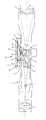
- the figure of the drawingschematically depicts a combination telescope and range finder in accordance with the invention apparatus in horizontal longitudinal section.
- the combination telescope and range finder apparatuscomprises a telescoping sight generally designated 1 provided with a telescope housing 2 one end of which receives an objective lens 3 and the other end of which receives an eyepiece 4 defining between them a beam path 5 .
- internal tube 7mounted for movement about a fulcrum 6 by means not shown in detail.
- internal tube 7contains a reversal system 8 , shown only schematically, as well as, at its forward end, a hairline graticule 9 which presents to observer a target mark 10 at the eyepiece 4 .
- the internal tube 7is pivoted about the fulcrum 6 by adjustment spindles (not shown).
- An electro-optical range finder based on laser principles generally designated 12is mounted on the external wall of the telescope housing 2 .
- the range finder 12is received in its own measuring housing 13 .
- the measuring housing 13contains emitter-receiver electronics 14 for laser measuring beams 15 and evaluation electronics for measuring the interval between an emitted and a received measuring beam 15 and for determining the distance derived therefrom.
- the emitter-receiver electronics 14is aimed at an opening 16 formed in the side wall of the telescoping housing 2 .
- the opening 16is disposed above an output window of a beam splitter 17 arranged in the internal tube 7 for coupling and decoupling measuring beams 15 into the beam path 5 directed towards the objective lens 3 .
- the beam splitter 17is disposed at the rear surface of the hairline graticule 9 .
- the target mark 10may also be formed at the front face of the beam splitter 17 .
- Movement of the internal tube 7 relative to the telescope housing 2would result in detrimental movement of the focus of the laser measuring beams 15 occurring at the locus of the target mark 10 .
- the resulting error at aiming for measurementwould be about the same as the sighting adjustment, usually 50-100 cm for 100 m of distance.
- the measuring beams 15are conducted a focally at least in a portion 15 ′ of the section extending between the receiving optics 14 and the beam splitter 17 .
- a group of lenses or lens 18 , 19which between them form the a focal portion 15 ′ of the mentioned measuring beam section.
- the emitter-receiver optics 14consists of spatially separated separate emitter and receiving components 20 , 21 with a beam splitter 22 , 23 in front of them to split the measuring beams 15 into emitted and received beams.
- the emitter and receiver components 20 , 21are arranged on circuit board 24 extending parallel to the axis of the telescope housing 2 , the circuit board also supporting the evaluation electronics for timing the interval and determining the distance.
- the beam splitter 22 , 23is made up of to opposing Z-deflector prisms aligned centrally relative to the opening 16 . In this manner, one half each of the aperture of the lens 3 is associated with the emitter component 20 and with the receiver component 21 , thus minimizing cross-talk from the emitter component to the receiving component. Moreover, the depicted prism arrangement makes possible a low structure of the measuring housing 13 and to arrange the evaluation electronics in a single plane.
- the measuring housing 13supports a display 25 for showing the measured distance and at its side it button 26 for commencing a measurement.
- a battery 27 for powering the range finderis arranged within the measuring housing 13 .
- the display 25may be arranged in the interior of the telescope housing 2 or at the margin of the image in the second image plane of the beam path 5 .
- the geometric beam splitter 22 , 23 shownany other kind of known beam splitter may be used, such as, for instance, a physical beam power splitter, such a 50%/50% splitter, a polarizing splitter, etc.
- the entire aperture of the objective lens 3is associated with the emitter component 20 and the receiver component 21 .
- the described structurerequires only a single additional opening, i.e. opening 16 , in the telescope housing 2 .
- the opening 16may be lastingly sealed by insertion of the lens 18 in a gas-tight manner, so that the interior space of the telescoping sight 1 which is sensitive to fogging is protected from penetration of humidity. Even during repair of the electronics, the telescoping sight remains sealed as the measuring housing 13 only need be removed.
- a laser diode range finder operating in a pulse interval methodis an especially suitable opto-electronic range finder.
- any other prior art electro-optical range finding apparatusmay be used.
Landscapes
- Physics & Mathematics (AREA)
- Engineering & Computer Science (AREA)
- General Physics & Mathematics (AREA)
- Remote Sensing (AREA)
- Radar, Positioning & Navigation (AREA)
- Computer Networks & Wireless Communication (AREA)
- Optics & Photonics (AREA)
- Electromagnetism (AREA)
- General Engineering & Computer Science (AREA)
- Astronomy & Astrophysics (AREA)
- Optical Radar Systems And Details Thereof (AREA)
- Telescopes (AREA)
- Measurement Of Optical Distance (AREA)
- Length Measuring Devices Characterised By Use Of Acoustic Means (AREA)
Abstract
Description
1. Background of the Invention
The present invention relates to a combination telescope and range finding apparatus, including
a telescoping sight provided with a telescope housing one end of which receives an objective lens and the other end of which receives an eyepiece and which defines a beam path therebetween,
an opto-electronic range finder provided with emitter-receiver optics for optical measuring beams and evaluation electronics for timing the interval between emission and reception of a measuring beam and for determining the distance on the basis thereof, and
a beam splitter within the beam path of the telescope housing for coupling and decoupling measuring beams into the part of the beam path directed toward the objective lens.
Such an apparatus is known, for instance, from European Patent EP 0,709,705. The publication discloses a telescoping sight for fire arms and is provided with a laser range finder integrated into the telescope housing. Emitted and received measuring beams are coupled and decoupled into the beam path toward the objective lens by separate beam splitters. The beam splitters are fixedly supported by the telescope housing, and for adjusting the sighting of the telescope the objective lens is mounted adjustably relative to the housing of the telescoping sight.
On the one hand, such a structure is complex as it requires two separate beam splitters and an adjustable objective lens; on the other hand, it is not possible simply to convert extant telescoping sights, for conventional telescoping sights utilize a movably mounted internal tube containing a target mark and reversal optics; no objective lens is provided which is mounted for special movements.
2. The Prior Art
It is, therefore, an object of the invention to provide a combination telescope and range finder apparatus which may be constructed in a particularly simple manner by conversion of existing telescopes. In an apparatus of the kind referred to supra, the object is accomplished by the an opening provided in a side wall of the telescope housing and the range finder being contained in a separate measuring housing adapted for mounting on said side wall, the emitter-receiver optics being directed toward the said opening.
In this manner, conversion of conventional telescoping sights available in the market is made simple.
In accordance with a preferred embodiment of the invention, the opening is hermetically sealed by a cover which is transparent to measuring beams. In this manner, the telescope is protected from moisture entering and from the possibility of fogging. The telescope remains sealed even in case of a repair.
The invention is particularly suitable for use with such commercially available telescopes in which the telescope housing is provided with an adjustably mounted internal tube of the kind which is traversed by the beam path, renders a target mark and optionally contains reversal optics. In such cases, the invention provides for the beam splitter to be mounted on the internal tube. More particularly, the target mark may be provided, preferably as a hairline graticule, on the side of the beam splitter facing the objective lens. This would require minimum adjustment of a telescoping sight.
In order in such cases to prevent shifting of the focus of the measuring beam coupled into the beam path relative to the target mark as a result of the internal tube being tilted relative to the telescope housing during sighting adjustments, a portion of the section of measuring beams between beam splitter and emitter-receiver optics in accordance with a preferred embodiment of the invention is a focal. This allows for movement of the internal tube relative to the telescope housing without the focus of the measuring beam being shifted in any significant way.
In accordance with the invention, this may be accomplished in a structurally simple and compact manner by each of the telescope housing and the internal tube or the beam splitter supporting a lens or group of lenses which between them form the mentioned focal portion.
In any case, emitter-receiver optics with spatially separated emitting and receiving components provided at their input with a beam splitter for correspondingly splitting of emitted and received measuring beams, is deemed to be particularly advantageous. In this fashion, cross talk from the emitter to the receiver component may be substantially reduced.
In this connection, it is particularly advantageous to structure the beam splitter as two opposing 90° deflector prisms with the mentioned opening aligned centrally thereof. This results in a measuring housing of particularly low structure.
Alternatively, the beam splitter may be a physical beam power splitter, e.g. a 50%/50% splifter, a polarizing splitter, etc., so that both emitted and received measuring beams may each utilize the entire surface of the objective lens.
In accordance with the invention, an especially compact structure of the measuring housing is obtained by arranging the emitter and receiver components axially spaced from each other on a circuit board extending parallel to the axis of the telescope housing.
The invention will be described in greater detail on the basis of an embodiment depicted in the accompanying drawing.
The figure of the drawing schematically depicts a combination telescope and range finder in accordance with the invention apparatus in horizontal longitudinal section.
The combination telescope and range finder apparatus comprises a telescoping sight generally designated1 provided with atelescope housing 2 one end of which receives anobjective lens 3 and the other end of which receives aneyepiece 4 defining between them abeam path 5.
In the interior of thetelescope housing 2 there is provided aninternal tube 7 mounted for movement about afulcrum 6 by means not shown in detail. In a manner well-known in technology,internal tube 7, contains areversal system 8, shown only schematically, as well as, at its forward end, ahairline graticule 9 which presents to observer atarget mark 10 at theeyepiece 4. For adjusting the sighting of the telescoping sight, i.e. for adjusting thesight axis 11 relative to the trajectory axis of a fire arm (not shown), theinternal tube 7 is pivoted about thefulcrum 6 by adjustment spindles (not shown).
An electro-optical range finder based on laser principles generally designated12 is mounted on the external wall of thetelescope housing 2. Therange finder 12 is received in itsown measuring housing 13. Themeasuring housing 13 contains emitter-receiver electronics 14 forlaser measuring beams 15 and evaluation electronics for measuring the interval between an emitted and a received measuringbeam 15 and for determining the distance derived therefrom.
The emitter-receiver electronics 14 is aimed at an opening16 formed in the side wall of thetelescoping housing 2. Theopening 16 is disposed above an output window of abeam splitter 17 arranged in theinternal tube 7 for coupling and decouplingmeasuring beams 15 into thebeam path 5 directed towards theobjective lens 3.
Thebeam splitter 17 is disposed at the rear surface of thehairline graticule 9. Alternatively, thetarget mark 10 may also be formed at the front face of thebeam splitter 17.
Movement of theinternal tube 7 relative to thetelescope housing 2 would result in detrimental movement of the focus of thelaser measuring beams 15 occurring at the locus of thetarget mark 10. The resulting error at aiming for measurement would be about the same as the sighting adjustment, usually 50-100 cm for 100 m of distance.
To prevent this, themeasuring beams 15 are conducted a focally at least in aportion 15′ of the section extending between thereceiving optics 14 and thebeam splitter 17. For this purpose there are mounted, in the vicinity of theopening 16 on the one hand and theinternal tube 7 or directly on thebeam splitter 17 on the other hand, a group of lenses orlens focal portion 15′ of the mentioned measuring beam section. In this manner (if the beam is decoupled laterally as shown in the figure) the vertical error is completely eliminated, and the horizontal error is reduced to about one tenth of the sighting adjustment, as a rule about 5-10 cm per 100 m. As regards the distance measurement such residual error is negligible.
In the embodiment shown, the emitter-receiver optics 14 consists of spatially separated separate emitter and receivingcomponents beam splitter measuring beams 15 into emitted and received beams. The emitter andreceiver components circuit board 24 extending parallel to the axis of thetelescope housing 2, the circuit board also supporting the evaluation electronics for timing the interval and determining the distance.
Thebeam splitter lens 3 is associated with theemitter component 20 and with thereceiver component 21, thus minimizing cross-talk from the emitter component to the receiving component. Moreover, the depicted prism arrangement makes possible a low structure of the measuringhousing 13 and to arrange the evaluation electronics in a single plane.
At its rear side themeasuring housing 13 supports adisplay 25 for showing the measured distance and at its side itbutton 26 for commencing a measurement. In addition, abattery 27 for powering the range finder is arranged within themeasuring housing 13.
Alternatively, thedisplay 25 may be arranged in the interior of thetelescope housing 2 or at the margin of the image in the second image plane of thebeam path 5. Instead of thegeometric beam splitter objective lens 3 is associated with theemitter component 20 and thereceiver component 21.
The described structure requires only a single additional opening, i.e. opening16, in thetelescope housing 2. The opening16 may be lastingly sealed by insertion of thelens 18 in a gas-tight manner, so that the interior space of thetelescoping sight 1 which is sensitive to fogging is protected from penetration of humidity. Even during repair of the electronics, the telescoping sight remains sealed as themeasuring housing 13 only need be removed.
A laser diode range finder operating in a pulse interval method is an especially suitable opto-electronic range finder. Alternatively, any other prior art electro-optical range finding apparatus may be used.
Claims (16)
1. A combination telescope and range finding apparatus, comprising:
an elongated telescope housing forming at opposite ends thereof first and second openings to define an optical axis, and a third opening in a side wall thereof;
an objective lens disposed in one of the first and second openings;
an eyepiece disposed in the other of the first and second openings;
an internal tube mounted within the telescope housing for selective pivotal movements relative to the optical axis and providing a target mark visible in the eyepiece;
a beam path extending between the objective lens and the eyepiece through the internal tube;
an opto-electronic range finder provided with means for emitting and receiving a measuring beam through the third opening to and from a subject and for determining the distance to the subject as a function of the interval between emission and reception of the measuring beam;
measuring beam deflection means disposed in the beam path within the internal tube for directing the measuring beam through the third opening and the eyepiece from and to the range finder; and
means for rendering a focal at least the portion of the measuring beam between the measuring beam deflection means and the range finder.
2. The apparatus ofclaim 1 , wherein the means for rendering the measuring beam a focal comprises at least one lens in at least one of the measuring beam deflection means and the telescope housing.
3. The apparatus ofclaim 2 , wherein the third opening is hermetically sealed by a cover transparent to the measuring beam.
4. The apparatus ofclaim 3 , wherein the cover constitutes the at least one lens.
5. The apparatus ofclaim 2 , wherein the target mark is disposed at a side of the measuring beam deflection means facing the objective lens.
6. The apparatus ofclaim 5 , wherein the target mark comprises a hair-line graticule.
7. The apparatus ofclaim 2 , wherein the range finder comprises spatially separated emitter and receiver components.
8. The apparatus ofclaim 7 , wherein the range finder further comprises a circuit board aligned parallel to the axis of the telescope housing and wherein the emitter and receiver components are mounted in axial alignment at opposite ends of the circuit board.
9. The apparatus ofclaim 8 , wherein the range finder further comprises deflecting means disposed to direct the measuring beam through the third opening from and to the emitter and receiver components into and out of the beam path.
10. The apparatus ofclaim 9 , wherein the deflecting means comprises a pair of 90° deflection prisms disposed on opposite sides of the third opening.
11. The apparatus ofclaim 9 , wherein the deflecting means comprises a physical beam power splitter.
12. The apparatus ofclaim 11 , wherein the beam power splitter is a 50%/50% splitter.
13. The apparatus ofclaim 9 , wherein the deflecting means comprises a polarizing splitter.
14. A telescoping sight adapted to be attached to an opto-electronic range finder of the kind transmitting and receiving a measuring beam for determining the distance to a subject as a function of the interval between transmission and receiption fo the measuring beam, comprising:
an elongated telescope housing forming at opposite ends thereof first and second openings to define an optical axis, and a third opening in a side wall thereof adapted to be aligned with the rangefinder for accommodating the bidirectional passage of a measuring beam;
an objective lens disposed in one of the first and second openings;
an eyepiece disposed in the other of the first and second openings;
an internal tube mounted within the telescope housing for selective pivotal movements relative to the optical axis and providing a target mark visible in the eyepiece;
a beam path extending between the objective lens and the eyepiece through the internal tube;
means supported in the internal tube and disposed in the beam path for deflecting a measuring beam between the third opening and the objective lens; and
means in at least one of the third opening and the means for deflecting the measuring beam for rendering the measuring beam afocal.
15. The telescoping sight ofclaim 14 , wherein the third opening is hermetically sealed by a cover transparent to the afocal beam.
16. The telescoping sight ofclaim 15 , wherein the cover comprises a lens.
Applications Claiming Priority (3)
| Application Number | Priority Date | Filing Date | Title |
|---|---|---|---|
| AT1030/99 | 1999-06-10 | ||
| AT0103099AAT407202B (en) | 1999-06-10 | 1999-06-10 | COMBINED SCOPE AND DISTANCE MEASURING DEVICE |
| PCT/AT2000/000136WO2000077554A1 (en) | 1999-06-10 | 2000-05-17 | Combined telescope and telemeter device |
Publications (1)
| Publication Number | Publication Date |
|---|---|
| US6583862B1true US6583862B1 (en) | 2003-06-24 |
Family
ID=3505158
Family Applications (1)
| Application Number | Title | Priority Date | Filing Date |
|---|---|---|---|
| US10/018,051Expired - LifetimeUS6583862B1 (en) | 1999-06-10 | 2000-05-17 | Combined telescope and telemeter device |
Country Status (5)
| Country | Link |
|---|---|
| US (1) | US6583862B1 (en) |
| EP (1) | EP1188087B1 (en) |
| AT (2) | AT407202B (en) |
| DE (1) | DE50004929D1 (en) |
| WO (1) | WO2000077554A1 (en) |
Cited By (41)
| Publication number | Priority date | Publication date | Assignee | Title |
|---|---|---|---|---|
| US20060010762A1 (en)* | 2004-06-17 | 2006-01-19 | Asia Optical Co., Inc. | Optical sight with rangefinder and assembly method for the same |
| US7106131B2 (en) | 2003-04-14 | 2006-09-12 | Realtek Semiconductor Corp. | Amplifying circuit |
| US20070068018A1 (en)* | 2005-06-03 | 2007-03-29 | Gilmore Sports Concepts, Inc. | Combination red dot sight and range indicator apparatus |
| DE102006035777A1 (en)* | 2006-08-01 | 2008-02-07 | Gerhard Kaufmann | Scope |
| US20090200376A1 (en)* | 2005-11-01 | 2009-08-13 | Leupold & Stevens, Inc. | Ballistic ranging methods and systems for inclined shooting |
| US20090199702A1 (en)* | 2003-11-04 | 2009-08-13 | Leupold & Stevens, Inc. | Ballistic range compensation for projectile weapon aiming based on ammunition classification |
| US20090296210A1 (en)* | 2005-02-10 | 2009-12-03 | Armin Schlierbach | Aiming telescope having a range finder |
| US20100309453A1 (en)* | 2009-05-29 | 2010-12-09 | Hilti Aktiengesellschaft | Laser instrument for electro-optical distance measurement |
| US20110032509A1 (en)* | 2009-08-07 | 2011-02-10 | Faro Technologies, Inc. | Absolute distance meter with optical switch |
| US20110167708A1 (en)* | 2010-01-12 | 2011-07-14 | Carson Cheng | Rubber Armored Rifle Scope with Integrated External Laser Sight |
| US20110176207A1 (en)* | 2010-01-19 | 2011-07-21 | Schmidt & Bender Gmbh & Co. Kg | Sighting telescope |
| US20120044475A1 (en)* | 2009-05-19 | 2012-02-23 | Dong Won Yang | Composite optical device for sighting targets and measuring distances |
| US8172139B1 (en) | 2010-11-22 | 2012-05-08 | Bitterroot Advance Ballistics Research, LLC | Ballistic ranging methods and systems for inclined shooting |
| USD688577S1 (en) | 2012-02-21 | 2013-08-27 | Faro Technologies, Inc. | Laser tracker |
| US8537376B2 (en) | 2011-04-15 | 2013-09-17 | Faro Technologies, Inc. | Enhanced position detector in laser tracker |
| WO2014130128A3 (en)* | 2012-12-05 | 2014-11-06 | Raytheon Company | Direct view optical sight with integrated laser system |
| US8902408B2 (en) | 2011-02-14 | 2014-12-02 | Faro Technologies Inc. | Laser tracker used with six degree-of-freedom probe having separable spherical retroreflector |
| US9007601B2 (en) | 2010-04-21 | 2015-04-14 | Faro Technologies, Inc. | Automatic measurement of dimensional data with a laser tracker |
| US9041914B2 (en) | 2013-03-15 | 2015-05-26 | Faro Technologies, Inc. | Three-dimensional coordinate scanner and method of operation |
| US9164173B2 (en) | 2011-04-15 | 2015-10-20 | Faro Technologies, Inc. | Laser tracker that uses a fiber-optic coupler and an achromatic launch to align and collimate two wavelengths of light |
| US9335124B2 (en)* | 2013-11-18 | 2016-05-10 | Cubic Corporation | Compact riflescope display adapter |
| US9377885B2 (en) | 2010-04-21 | 2016-06-28 | Faro Technologies, Inc. | Method and apparatus for locking onto a retroreflector with a laser tracker |
| US9395174B2 (en) | 2014-06-27 | 2016-07-19 | Faro Technologies, Inc. | Determining retroreflector orientation by optimizing spatial fit |
| US9400170B2 (en) | 2010-04-21 | 2016-07-26 | Faro Technologies, Inc. | Automatic measurement of dimensional data within an acceptance region by a laser tracker |
| US9453913B2 (en) | 2008-11-17 | 2016-09-27 | Faro Technologies, Inc. | Target apparatus for three-dimensional measurement system |
| US9482755B2 (en) | 2008-11-17 | 2016-11-01 | Faro Technologies, Inc. | Measurement system having air temperature compensation between a target and a laser tracker |
| US9482529B2 (en) | 2011-04-15 | 2016-11-01 | Faro Technologies, Inc. | Three-dimensional coordinate scanner and method of operation |
| EP1723384B1 (en)* | 2004-03-10 | 2017-04-19 | Raytheon Company | Method and apparatus for range finding with a single aperture |
| US9638507B2 (en) | 2012-01-27 | 2017-05-02 | Faro Technologies, Inc. | Measurement machine utilizing a barcode to identify an inspection plan for an object |
| US9686532B2 (en) | 2011-04-15 | 2017-06-20 | Faro Technologies, Inc. | System and method of acquiring three-dimensional coordinates using multiple coordinate measurement devices |
| US9772394B2 (en) | 2010-04-21 | 2017-09-26 | Faro Technologies, Inc. | Method and apparatus for following an operator and locking onto a retroreflector with a laser tracker |
| US9791244B2 (en) | 2014-11-17 | 2017-10-17 | Cubic Corporation | Rifle scope targeting display adapter mount |
| US20180224650A1 (en)* | 2017-02-06 | 2018-08-09 | Sheltered Wings, Inc. D/B/A Vortex Optics | Viewing Optic with an Integrated Display System |
| US10175041B2 (en)* | 2015-03-27 | 2019-01-08 | Olympus Corporation | Measuring head and eccentricity measuring device including the same |
| US10274286B2 (en) | 2014-11-17 | 2019-04-30 | Cubic Corporation | Rifle scope targeting display adapter |
| US10443984B2 (en) | 2014-11-17 | 2019-10-15 | Cubic Corporation | Low-cost rifle scope display adapter |
| US10534166B2 (en) | 2016-09-22 | 2020-01-14 | Lightforce Usa, Inc. | Optical targeting information projection system |
| US11473873B2 (en) | 2019-01-18 | 2022-10-18 | Sheltered Wings, Inc. | Viewing optic with round counter system |
| US11480781B2 (en) | 2018-04-20 | 2022-10-25 | Sheltered Wings, Inc. | Viewing optic with direct active reticle targeting |
| US11675180B2 (en) | 2018-01-12 | 2023-06-13 | Sheltered Wings, Inc. | Viewing optic with an integrated display system |
| US20240426578A1 (en)* | 2023-06-21 | 2024-12-26 | Bushnell Inc. | Local connected networks for outdoor activities |
Families Citing this family (4)
| Publication number | Priority date | Publication date | Assignee | Title |
|---|---|---|---|---|
| DE102004048907A1 (en)* | 2004-10-06 | 2006-04-27 | S.A.T. Swiss Arms Technology Ag | Sighting device for a firearm and firearm with a mounting option for a sighting device |
| AT506437B1 (en)* | 2008-01-31 | 2011-08-15 | Swarovski Optik Kg | OBSERVATION DEVICE WITH DISTANCE KNIFE |
| DE102009039851A1 (en) | 2009-09-03 | 2011-05-12 | Carl Zeiss Sports Optics Gmbh | Scope |
| DE102013102826B4 (en)* | 2013-03-19 | 2016-10-06 | Schmidt & Bender Gmbh & Co. Kg | Scope |
Citations (27)
| Publication number | Priority date | Publication date | Assignee | Title |
|---|---|---|---|---|
| US3698812A (en)* | 1969-08-11 | 1972-10-17 | Hughes Aircraft Co | Multi-function telescope |
| US3721488A (en)* | 1970-05-29 | 1973-03-20 | Zeiss Stiftung | Focusing arrangment for afocal telescopes |
| US3868169A (en)* | 1972-02-28 | 1975-02-25 | Contraves Ag | Observation periscope which can be combined with a laser device |
| DE2556673A1 (en) | 1975-01-07 | 1976-07-08 | Hooker Chemicals Plastics Corp | METHOD OF VAPORATING LIQUID AND DEVICE FOR IT |
| US4108551A (en)* | 1975-12-29 | 1978-08-22 | Societe D'etudes Et De Realisations Electroniques | Observation and aiming apparatus, particularly on a vehicle |
| US4116528A (en)* | 1975-04-10 | 1978-09-26 | U.S. Philips Corporation | Optical viewing device of the periscope type with rotating means for focussing |
| DE2924478A1 (en) | 1978-06-22 | 1980-01-17 | Bofors Ab | LASER RANGE MEASURING DEVICE |
| US4284326A (en)* | 1979-03-29 | 1981-08-18 | Werkzeugmaschinenfabrik Oerlikon-Buhrle Ag | Apparatus for eliminating external weather effects from the objective lens system of an aiming periscope installed at an armed vehicle |
| JPS58102108A (en) | 1981-12-14 | 1983-06-17 | Mitsubishi Electric Corp | Laser range finder |
| US4483587A (en) | 1981-12-22 | 1984-11-20 | Societe De Fabrication D'instruments De Mesure | Sighting and aiming arrangement for use during day or night |
| EP0165170A2 (en) | 1984-06-15 | 1985-12-18 | Societe De Fabrication D'instruments De Mesure (S.F.I.M.) | Device for sighting, recognising and tracking a target |
| US4576451A (en)* | 1982-01-08 | 1986-03-18 | Hakko Seiki Kabushiki Kaisha | Aiming telescope |
| US4611911A (en) | 1983-12-26 | 1986-09-16 | Nippon Kogaku K.K. | Electro-optical distance measuring device |
| GB2187353A (en) | 1986-01-03 | 1987-09-03 | Hale Parker Ltd | Rifle sight |
| US5022723A (en)* | 1988-07-13 | 1991-06-11 | Wild Leitz Gmbh | Panoramic periscope for two spectrum ranges |
| US5052801A (en) | 1989-12-19 | 1991-10-01 | Damocles Engineering, Inc. | Compact laser-assisted weapon sight |
| US5144479A (en)* | 1990-06-21 | 1992-09-01 | Yehudit Aharon | Combined telescope and autocollimator |
| DE4218118A1 (en) | 1992-06-02 | 1993-12-09 | Heller Wolfgang Dipl Holzw | Adjustable telescopic sight - brings target point adjustment dependent on distance into accordance with adjustment dependent on ballistics |
| US5291263A (en)* | 1992-03-18 | 1994-03-01 | Korea Advanced Institute Of Science And Technology | Laser range finder using a nonlinear crystal |
| US5313409A (en)* | 1989-04-06 | 1994-05-17 | Geotronics | Arrangement for performing position determination |
| EP0709705A2 (en) | 1994-10-31 | 1996-05-01 | Swarovski Optik Kg | Telescopic sight |
| AT402565B (en) | 1990-02-09 | 1997-06-25 | Messerschmitt Boelkow Blohm | METHOD FOR VISOR ADJUSTMENT IN WEAPON SYSTEMS |
| US5892617A (en)* | 1997-07-28 | 1999-04-06 | Wallace; Robert E. | Multi-function day/night observation, ranging, and sighting device and method of its operation |
| US6204961B1 (en)* | 1995-09-18 | 2001-03-20 | Litton Systems, Inc. | Day and night sighting system |
| US6333783B1 (en)* | 1999-05-21 | 2001-12-25 | Kabushiki Kaisha Topcon | Distance measuring system |
| US6344894B1 (en)* | 2000-01-05 | 2002-02-05 | Asia Optical Co., Ltd | Optical axis adjusting structure for a range finder |
| US6442854B1 (en)* | 1999-08-27 | 2002-09-03 | Wuhan Changjiang Optics Electron Co. Ltd. | Fast alignment telescopic sight |
- 1999
- 1999-06-10ATAT0103099Apatent/AT407202B/ennot_activeIP Right Cessation
- 2000
- 2000-05-17USUS10/018,051patent/US6583862B1/ennot_activeExpired - Lifetime
- 2000-05-17EPEP00926526Apatent/EP1188087B1/ennot_activeExpired - Lifetime
- 2000-05-17WOPCT/AT2000/000136patent/WO2000077554A1/enactiveIP Right Grant
- 2000-05-17ATAT00926526Tpatent/ATE257249T1/enactive
- 2000-05-17DEDE50004929Tpatent/DE50004929D1/ennot_activeExpired - Lifetime
Patent Citations (27)
| Publication number | Priority date | Publication date | Assignee | Title |
|---|---|---|---|---|
| US3698812A (en)* | 1969-08-11 | 1972-10-17 | Hughes Aircraft Co | Multi-function telescope |
| US3721488A (en)* | 1970-05-29 | 1973-03-20 | Zeiss Stiftung | Focusing arrangment for afocal telescopes |
| US3868169A (en)* | 1972-02-28 | 1975-02-25 | Contraves Ag | Observation periscope which can be combined with a laser device |
| DE2556673A1 (en) | 1975-01-07 | 1976-07-08 | Hooker Chemicals Plastics Corp | METHOD OF VAPORATING LIQUID AND DEVICE FOR IT |
| US4116528A (en)* | 1975-04-10 | 1978-09-26 | U.S. Philips Corporation | Optical viewing device of the periscope type with rotating means for focussing |
| US4108551A (en)* | 1975-12-29 | 1978-08-22 | Societe D'etudes Et De Realisations Electroniques | Observation and aiming apparatus, particularly on a vehicle |
| DE2924478A1 (en) | 1978-06-22 | 1980-01-17 | Bofors Ab | LASER RANGE MEASURING DEVICE |
| US4284326A (en)* | 1979-03-29 | 1981-08-18 | Werkzeugmaschinenfabrik Oerlikon-Buhrle Ag | Apparatus for eliminating external weather effects from the objective lens system of an aiming periscope installed at an armed vehicle |
| JPS58102108A (en) | 1981-12-14 | 1983-06-17 | Mitsubishi Electric Corp | Laser range finder |
| US4483587A (en) | 1981-12-22 | 1984-11-20 | Societe De Fabrication D'instruments De Mesure | Sighting and aiming arrangement for use during day or night |
| US4576451A (en)* | 1982-01-08 | 1986-03-18 | Hakko Seiki Kabushiki Kaisha | Aiming telescope |
| US4611911A (en) | 1983-12-26 | 1986-09-16 | Nippon Kogaku K.K. | Electro-optical distance measuring device |
| EP0165170A2 (en) | 1984-06-15 | 1985-12-18 | Societe De Fabrication D'instruments De Mesure (S.F.I.M.) | Device for sighting, recognising and tracking a target |
| GB2187353A (en) | 1986-01-03 | 1987-09-03 | Hale Parker Ltd | Rifle sight |
| US5022723A (en)* | 1988-07-13 | 1991-06-11 | Wild Leitz Gmbh | Panoramic periscope for two spectrum ranges |
| US5313409A (en)* | 1989-04-06 | 1994-05-17 | Geotronics | Arrangement for performing position determination |
| US5052801A (en) | 1989-12-19 | 1991-10-01 | Damocles Engineering, Inc. | Compact laser-assisted weapon sight |
| AT402565B (en) | 1990-02-09 | 1997-06-25 | Messerschmitt Boelkow Blohm | METHOD FOR VISOR ADJUSTMENT IN WEAPON SYSTEMS |
| US5144479A (en)* | 1990-06-21 | 1992-09-01 | Yehudit Aharon | Combined telescope and autocollimator |
| US5291263A (en)* | 1992-03-18 | 1994-03-01 | Korea Advanced Institute Of Science And Technology | Laser range finder using a nonlinear crystal |
| DE4218118A1 (en) | 1992-06-02 | 1993-12-09 | Heller Wolfgang Dipl Holzw | Adjustable telescopic sight - brings target point adjustment dependent on distance into accordance with adjustment dependent on ballistics |
| EP0709705A2 (en) | 1994-10-31 | 1996-05-01 | Swarovski Optik Kg | Telescopic sight |
| US6204961B1 (en)* | 1995-09-18 | 2001-03-20 | Litton Systems, Inc. | Day and night sighting system |
| US5892617A (en)* | 1997-07-28 | 1999-04-06 | Wallace; Robert E. | Multi-function day/night observation, ranging, and sighting device and method of its operation |
| US6333783B1 (en)* | 1999-05-21 | 2001-12-25 | Kabushiki Kaisha Topcon | Distance measuring system |
| US6442854B1 (en)* | 1999-08-27 | 2002-09-03 | Wuhan Changjiang Optics Electron Co. Ltd. | Fast alignment telescopic sight |
| US6344894B1 (en)* | 2000-01-05 | 2002-02-05 | Asia Optical Co., Ltd | Optical axis adjusting structure for a range finder |
Cited By (91)
| Publication number | Priority date | Publication date | Assignee | Title |
|---|---|---|---|---|
| US7106131B2 (en) | 2003-04-14 | 2006-09-12 | Realtek Semiconductor Corp. | Amplifying circuit |
| US20090199702A1 (en)* | 2003-11-04 | 2009-08-13 | Leupold & Stevens, Inc. | Ballistic range compensation for projectile weapon aiming based on ammunition classification |
| US8286384B2 (en) | 2003-11-04 | 2012-10-16 | Leupold & Stevens, Inc. | Ballistic range compensation for projectile weapon aiming based on ammunition classification |
| EP1723384B1 (en)* | 2004-03-10 | 2017-04-19 | Raytheon Company | Method and apparatus for range finding with a single aperture |
| US20060010762A1 (en)* | 2004-06-17 | 2006-01-19 | Asia Optical Co., Inc. | Optical sight with rangefinder and assembly method for the same |
| US20090296210A1 (en)* | 2005-02-10 | 2009-12-03 | Armin Schlierbach | Aiming telescope having a range finder |
| US7990523B2 (en) | 2005-02-10 | 2011-08-02 | Carl Zeiss Sports Optics Gmbh | Aiming telescope having a range finder |
| US20070068018A1 (en)* | 2005-06-03 | 2007-03-29 | Gilmore Sports Concepts, Inc. | Combination red dot sight and range indicator apparatus |
| WO2006133029A3 (en)* | 2005-06-03 | 2009-04-16 | Gilmore Sports Concepts Inc | Combination red dot sight and range indicator apparatus |
| US8393109B2 (en)* | 2005-06-03 | 2013-03-12 | Gilmore Sports Concepts, Inc. | Combination red dot sight and range indicator apparatus |
| US7690145B2 (en) | 2005-11-01 | 2010-04-06 | Leupold & Stevens, Inc. | Ballistic ranging methods and systems for inclined shooting |
| US8959823B2 (en) | 2005-11-01 | 2015-02-24 | Leupold & Stevens, Inc. | Ranging methods for inclined shooting of projectile weapons |
| US9482489B2 (en) | 2005-11-01 | 2016-11-01 | Leupold & Stevens, Inc. | Ranging methods for inclined shooting of projectile weapon |
| US7654029B2 (en) | 2005-11-01 | 2010-02-02 | Leupold & Stevens, Inc. | Ballistic ranging methods and systems for inclined shooting |
| US8046951B2 (en) | 2005-11-01 | 2011-11-01 | Leupold & Stevens, Inc. | Rangefinders and aiming methods using projectile grouping |
| US20100282845A1 (en)* | 2005-11-01 | 2010-11-11 | Peters Victoria J | Rangefinders and aiming methods using projectile grouping |
| US20090200376A1 (en)* | 2005-11-01 | 2009-08-13 | Leupold & Stevens, Inc. | Ballistic ranging methods and systems for inclined shooting |
| US8448372B2 (en) | 2005-11-01 | 2013-05-28 | Leupold & Stevens, Inc. | Rangefinders for inclined shooting of projectile weapons |
| DE102006035777A1 (en)* | 2006-08-01 | 2008-02-07 | Gerhard Kaufmann | Scope |
| US8783568B2 (en) | 2006-08-01 | 2014-07-22 | Gerhard Kaufmann | Telescopic sight |
| DE102006035777B4 (en)* | 2006-08-01 | 2009-12-31 | Gerhard Kaufmann | Scope |
| US9453913B2 (en) | 2008-11-17 | 2016-09-27 | Faro Technologies, Inc. | Target apparatus for three-dimensional measurement system |
| US9482755B2 (en) | 2008-11-17 | 2016-11-01 | Faro Technologies, Inc. | Measurement system having air temperature compensation between a target and a laser tracker |
| US20120044475A1 (en)* | 2009-05-19 | 2012-02-23 | Dong Won Yang | Composite optical device for sighting targets and measuring distances |
| US9200869B2 (en)* | 2009-05-19 | 2015-12-01 | Agency For Defense Development | Composite optical device for sighting targets and measuring distances |
| US20100309453A1 (en)* | 2009-05-29 | 2010-12-09 | Hilti Aktiengesellschaft | Laser instrument for electro-optical distance measurement |
| US8570493B2 (en) | 2009-08-07 | 2013-10-29 | Faro Technologies, Inc. | Absolute distance meter that uses a fiber-optic switch to reduce drift |
| US8659749B2 (en) | 2009-08-07 | 2014-02-25 | Faro Technologies, Inc. | Absolute distance meter with optical switch |
| US20110032509A1 (en)* | 2009-08-07 | 2011-02-10 | Faro Technologies, Inc. | Absolute distance meter with optical switch |
| US20110167708A1 (en)* | 2010-01-12 | 2011-07-14 | Carson Cheng | Rubber Armored Rifle Scope with Integrated External Laser Sight |
| US20110176207A1 (en)* | 2010-01-19 | 2011-07-21 | Schmidt & Bender Gmbh & Co. Kg | Sighting telescope |
| US8804237B2 (en)* | 2010-01-19 | 2014-08-12 | Schmidt & Bender Gmbh Co. Kg | Sighting telescope with high shooting reliability under different conditions |
| US9772394B2 (en) | 2010-04-21 | 2017-09-26 | Faro Technologies, Inc. | Method and apparatus for following an operator and locking onto a retroreflector with a laser tracker |
| US10480929B2 (en) | 2010-04-21 | 2019-11-19 | Faro Technologies, Inc. | Method and apparatus for following an operator and locking onto a retroreflector with a laser tracker |
| US9400170B2 (en) | 2010-04-21 | 2016-07-26 | Faro Technologies, Inc. | Automatic measurement of dimensional data within an acceptance region by a laser tracker |
| US10209059B2 (en) | 2010-04-21 | 2019-02-19 | Faro Technologies, Inc. | Method and apparatus for following an operator and locking onto a retroreflector with a laser tracker |
| US9007601B2 (en) | 2010-04-21 | 2015-04-14 | Faro Technologies, Inc. | Automatic measurement of dimensional data with a laser tracker |
| US9377885B2 (en) | 2010-04-21 | 2016-06-28 | Faro Technologies, Inc. | Method and apparatus for locking onto a retroreflector with a laser tracker |
| US9146094B2 (en) | 2010-04-21 | 2015-09-29 | Faro Technologies, Inc. | Automatic measurement of dimensional data with a laser tracker |
| US8172139B1 (en) | 2010-11-22 | 2012-05-08 | Bitterroot Advance Ballistics Research, LLC | Ballistic ranging methods and systems for inclined shooting |
| US9835413B2 (en) | 2010-11-22 | 2017-12-05 | Leupold & Stevens, Inc. | Ballistic ranging methods and systems for inclined shooting |
| US8902408B2 (en) | 2011-02-14 | 2014-12-02 | Faro Technologies Inc. | Laser tracker used with six degree-of-freedom probe having separable spherical retroreflector |
| US9164173B2 (en) | 2011-04-15 | 2015-10-20 | Faro Technologies, Inc. | Laser tracker that uses a fiber-optic coupler and an achromatic launch to align and collimate two wavelengths of light |
| US10119805B2 (en) | 2011-04-15 | 2018-11-06 | Faro Technologies, Inc. | Three-dimensional coordinate scanner and method of operation |
| US9151830B2 (en) | 2011-04-15 | 2015-10-06 | Faro Technologies, Inc. | Six degree-of-freedom laser tracker that cooperates with a remote structured-light scanner |
| US9207309B2 (en) | 2011-04-15 | 2015-12-08 | Faro Technologies, Inc. | Six degree-of-freedom laser tracker that cooperates with a remote line scanner |
| US10578423B2 (en) | 2011-04-15 | 2020-03-03 | Faro Technologies, Inc. | Diagnosing multipath interference and eliminating multipath interference in 3D scanners using projection patterns |
| US10302413B2 (en) | 2011-04-15 | 2019-05-28 | Faro Technologies, Inc. | Six degree-of-freedom laser tracker that cooperates with a remote sensor |
| US10267619B2 (en) | 2011-04-15 | 2019-04-23 | Faro Technologies, Inc. | Three-dimensional coordinate scanner and method of operation |
| US8908154B2 (en) | 2011-04-15 | 2014-12-09 | Faro Technologies, Inc. | Laser tracker that combines two different wavelengths with a fiber-optic coupler |
| US9448059B2 (en) | 2011-04-15 | 2016-09-20 | Faro Technologies, Inc. | Three-dimensional scanner with external tactical probe and illuminated guidance |
| US8537376B2 (en) | 2011-04-15 | 2013-09-17 | Faro Technologies, Inc. | Enhanced position detector in laser tracker |
| US9453717B2 (en) | 2011-04-15 | 2016-09-27 | Faro Technologies, Inc. | Diagnosing multipath interference and eliminating multipath interference in 3D scanners using projection patterns |
| US9157987B2 (en) | 2011-04-15 | 2015-10-13 | Faro Technologies, Inc. | Absolute distance meter based on an undersampling method |
| US8848203B2 (en) | 2011-04-15 | 2014-09-30 | Faro Technologies, Inc. | Six degree-of-freedom laser tracker that cooperates with a remote projector to convey information |
| US9482746B2 (en) | 2011-04-15 | 2016-11-01 | Faro Technologies, Inc. | Six degree-of-freedom laser tracker that cooperates with a remote sensor |
| US8842259B2 (en) | 2011-04-15 | 2014-09-23 | Faro Technologies, Inc. | Laser tracker with enhanced handling features |
| US9482529B2 (en) | 2011-04-15 | 2016-11-01 | Faro Technologies, Inc. | Three-dimensional coordinate scanner and method of operation |
| US9494412B2 (en) | 2011-04-15 | 2016-11-15 | Faro Technologies, Inc. | Diagnosing multipath interference and eliminating multipath interference in 3D scanners using automated repositioning |
| US8558992B2 (en) | 2011-04-15 | 2013-10-15 | Faro Technologies, Inc. | Laser tracker with enhanced illumination indicators |
| US8681320B2 (en) | 2011-04-15 | 2014-03-25 | Faro Technologies, Inc. | Gimbal instrument having a prealigned and replaceable optics bench |
| US9686532B2 (en) | 2011-04-15 | 2017-06-20 | Faro Technologies, Inc. | System and method of acquiring three-dimensional coordinates using multiple coordinate measurement devices |
| US9638507B2 (en) | 2012-01-27 | 2017-05-02 | Faro Technologies, Inc. | Measurement machine utilizing a barcode to identify an inspection plan for an object |
| USD705678S1 (en) | 2012-02-21 | 2014-05-27 | Faro Technologies, Inc. | Laser tracker |
| USD688577S1 (en) | 2012-02-21 | 2013-08-27 | Faro Technologies, Inc. | Laser tracker |
| WO2014130128A3 (en)* | 2012-12-05 | 2014-11-06 | Raytheon Company | Direct view optical sight with integrated laser system |
| US9632304B2 (en) | 2012-12-05 | 2017-04-25 | Raytheon Company | Direct view optical sight with integrated laser system |
| US9482514B2 (en) | 2013-03-15 | 2016-11-01 | Faro Technologies, Inc. | Diagnosing multipath interference and eliminating multipath interference in 3D scanners by directed probing |
| US9041914B2 (en) | 2013-03-15 | 2015-05-26 | Faro Technologies, Inc. | Three-dimensional coordinate scanner and method of operation |
| US9335124B2 (en)* | 2013-11-18 | 2016-05-10 | Cubic Corporation | Compact riflescope display adapter |
| US9395174B2 (en) | 2014-06-27 | 2016-07-19 | Faro Technologies, Inc. | Determining retroreflector orientation by optimizing spatial fit |
| US9791244B2 (en) | 2014-11-17 | 2017-10-17 | Cubic Corporation | Rifle scope targeting display adapter mount |
| US10274286B2 (en) | 2014-11-17 | 2019-04-30 | Cubic Corporation | Rifle scope targeting display adapter |
| US10443984B2 (en) | 2014-11-17 | 2019-10-15 | Cubic Corporation | Low-cost rifle scope display adapter |
| US10175041B2 (en)* | 2015-03-27 | 2019-01-08 | Olympus Corporation | Measuring head and eccentricity measuring device including the same |
| US10534166B2 (en) | 2016-09-22 | 2020-01-14 | Lightforce Usa, Inc. | Optical targeting information projection system |
| US11927739B2 (en) | 2017-02-06 | 2024-03-12 | Sheltered Wings, Inc. | Viewing optic with an integrated display system |
| US20180224650A1 (en)* | 2017-02-06 | 2018-08-09 | Sheltered Wings, Inc. D/B/A Vortex Optics | Viewing Optic with an Integrated Display System |
| US10866402B2 (en)* | 2017-02-06 | 2020-12-15 | Sheltered Wings, Inc. | Viewing optic with an integrated display system |
| US11187884B2 (en) | 2017-02-06 | 2021-11-30 | Sheltered Wings, Inc. | Viewing optic with an integrated display system |
| US12270984B2 (en) | 2017-02-06 | 2025-04-08 | Sheltered Wings, Inc. | Viewing optic with an integrated display system |
| US11940612B2 (en) | 2017-02-06 | 2024-03-26 | Sheltered Wings, Inc. | Viewing optic with an integrated display system |
| US11619807B2 (en) | 2017-02-06 | 2023-04-04 | Sheltered Wings, Inc. | Viewing optic with an integrated display system |
| US10852524B2 (en) | 2017-02-06 | 2020-12-01 | Sheltered Wings, Inc. | Viewing optic with an integrated display system |
| US11921279B2 (en) | 2017-02-06 | 2024-03-05 | Sheltered Wings, Inc. | Viewing optic with an integrated display system |
| US11675180B2 (en) | 2018-01-12 | 2023-06-13 | Sheltered Wings, Inc. | Viewing optic with an integrated display system |
| US12174363B2 (en) | 2018-01-12 | 2024-12-24 | Sheltered Wings Inc. | Viewing optic with an integrated display system |
| US11480781B2 (en) | 2018-04-20 | 2022-10-25 | Sheltered Wings, Inc. | Viewing optic with direct active reticle targeting |
| US12085362B2 (en) | 2019-01-18 | 2024-09-10 | Sheltered Wings, Inc. | Viewing optic with round counter system |
| US11473873B2 (en) | 2019-01-18 | 2022-10-18 | Sheltered Wings, Inc. | Viewing optic with round counter system |
| US20240426578A1 (en)* | 2023-06-21 | 2024-12-26 | Bushnell Inc. | Local connected networks for outdoor activities |
Also Published As
| Publication number | Publication date |
|---|---|
| ATA103099A (en) | 2000-05-15 |
| WO2000077554A1 (en) | 2000-12-21 |
| EP1188087A1 (en) | 2002-03-20 |
| DE50004929D1 (en) | 2004-02-05 |
| AT407202B (en) | 2001-01-25 |
| ATE257249T1 (en) | 2004-01-15 |
| EP1188087B1 (en) | 2004-01-02 |
Similar Documents
| Publication | Publication Date | Title |
|---|---|---|
| US6583862B1 (en) | Combined telescope and telemeter device | |
| US11460296B2 (en) | Observation device with a distance meter | |
| US6204961B1 (en) | Day and night sighting system | |
| US5517297A (en) | Rangefinder with transmitter, receiver, and viewfinder on a single common optical axis | |
| US8132353B2 (en) | Laser sight | |
| US20050219690A1 (en) | Riflescope and the laser rangefinder used therein | |
| US7271954B2 (en) | Binoculars with an integrated laser rangefinder | |
| US9151603B2 (en) | Compact folded signal transmission and image viewing pathway design and visual display technique for laser rangefinding instruments | |
| US20100265490A1 (en) | Range binoculars | |
| US8599482B2 (en) | Telescopic sight | |
| GB2024558A (en) | Laser Range Finder | |
| JP7716768B2 (en) | Compact monocular telescopic laser rangefinder | |
| KR20200038678A (en) | Complex optical sighting device | |
| US7349073B2 (en) | Efficient optical system and beam pathway design for laser-based distance measuring device | |
| GB1600191A (en) | Electrooptical range finders | |
| RU2307322C2 (en) | Laser range-finder | |
| US7599116B2 (en) | Display device for telescope system | |
| RU63054U1 (en) | LASER RANGEFINDER | |
| FI108367B (en) | An elliptical spacer designed to be arranged in a night vision device | |
| US20230221095A1 (en) | Compact Rangefinder Scope | |
| RU2443976C1 (en) | Laser range-finding binoculars | |
| AU2019366763B2 (en) | Directed-energy weapon and method for displaying the position of an impact point of the directed-energy weapon | |
| CN118519160A (en) | Binoculars type distance meter | |
| JP2000221035A (en) | Reflecting mirror for af surveying machine | |
| EA001581B1 (en) | Laser distance meter |
Legal Events
| Date | Code | Title | Description |
|---|---|---|---|
| STCF | Information on status: patent grant | Free format text:PATENTED CASE | |
| FPAY | Fee payment | Year of fee payment:4 | |
| FPAY | Fee payment | Year of fee payment:8 | |
| FPAY | Fee payment | Year of fee payment:12 |