US6583821B1 - Synchronizing apparatus for a compressed audio/video signal receiver - Google Patents
Synchronizing apparatus for a compressed audio/video signal receiverDownload PDFInfo
- Publication number
- US6583821B1 US6583821B1US09/358,070US35807099AUS6583821B1US 6583821 B1US6583821 B1US 6583821B1US 35807099 AUS35807099 AUS 35807099AUS 6583821 B1US6583821 B1US 6583821B1
- Authority
- US
- United States
- Prior art keywords
- audio
- signal
- video
- synchronization
- decompressed
- Prior art date
- Legal status (The legal status is an assumption and is not a legal conclusion. Google has not performed a legal analysis and makes no representation as to the accuracy of the status listed.)
- Expired - Lifetime
Links
- 230000001360synchronised effectEffects0.000claimsabstractdescription15
- 230000005236sound signalEffects0.000claimsdescription24
- 238000000034methodMethods0.000claimsdescription13
- 238000001514detection methodMethods0.000claimsdescription3
- 239000000872bufferSubstances0.000description13
- 230000015654memoryEffects0.000description13
- 230000006870functionEffects0.000description11
- 230000005540biological transmissionEffects0.000description6
- 238000010586diagramMethods0.000description4
- 230000000694effectsEffects0.000description4
- 238000005070samplingMethods0.000description4
- 238000006243chemical reactionMethods0.000description3
- 230000006835compressionEffects0.000description3
- 238000007906compressionMethods0.000description3
- 230000007774longtermEffects0.000description3
- 230000008520organizationEffects0.000description3
- 230000001143conditioned effectEffects0.000description2
- 230000006837decompressionEffects0.000description2
- 230000001419dependent effectEffects0.000description2
- 230000036039immunityEffects0.000description2
- 238000004519manufacturing processMethods0.000description2
- 230000008054signal transmissionEffects0.000description2
- 239000000725suspensionSubstances0.000description2
- 230000002123temporal effectEffects0.000description2
- 101000969688Homo sapiens Macrophage-expressed gene 1 proteinProteins0.000description1
- 102100021285Macrophage-expressed gene 1 proteinHuman genes0.000description1
- 230000001594aberrant effectEffects0.000description1
- 230000003044adaptive effectEffects0.000description1
- 230000001934delayEffects0.000description1
- 230000007246mechanismEffects0.000description1
- 238000010606normalizationMethods0.000description1
- 239000013641positive controlSubstances0.000description1
Images


Classifications
- H—ELECTRICITY
- H04—ELECTRIC COMMUNICATION TECHNIQUE
- H04N—PICTORIAL COMMUNICATION, e.g. TELEVISION
- H04N21/00—Selective content distribution, e.g. interactive television or video on demand [VOD]
- H04N21/40—Client devices specifically adapted for the reception of or interaction with content, e.g. set-top-box [STB]; Operations thereof
- H04N21/43—Processing of content or additional data, e.g. demultiplexing additional data from a digital video stream; Elementary client operations, e.g. monitoring of home network or synchronising decoder's clock; Client middleware
- H04N21/439—Processing of audio elementary streams
- H04N21/4396—Processing of audio elementary streams by muting the audio signal
- H—ELECTRICITY
- H04—ELECTRIC COMMUNICATION TECHNIQUE
- H04N—PICTORIAL COMMUNICATION, e.g. TELEVISION
- H04N21/00—Selective content distribution, e.g. interactive television or video on demand [VOD]
- H04N21/20—Servers specifically adapted for the distribution of content, e.g. VOD servers; Operations thereof
- H04N21/23—Processing of content or additional data; Elementary server operations; Server middleware
- H04N21/236—Assembling of a multiplex stream, e.g. transport stream, by combining a video stream with other content or additional data, e.g. inserting a URL [Uniform Resource Locator] into a video stream, multiplexing software data into a video stream; Remultiplexing of multiplex streams; Insertion of stuffing bits into the multiplex stream, e.g. to obtain a constant bit-rate; Assembling of a packetised elementary stream
- H04N21/2368—Multiplexing of audio and video streams
- H—ELECTRICITY
- H04—ELECTRIC COMMUNICATION TECHNIQUE
- H04N—PICTORIAL COMMUNICATION, e.g. TELEVISION
- H04N21/00—Selective content distribution, e.g. interactive television or video on demand [VOD]
- H04N21/40—Client devices specifically adapted for the reception of or interaction with content, e.g. set-top-box [STB]; Operations thereof
- H04N21/43—Processing of content or additional data, e.g. demultiplexing additional data from a digital video stream; Elementary client operations, e.g. monitoring of home network or synchronising decoder's clock; Client middleware
- H04N21/4302—Content synchronisation processes, e.g. decoder synchronisation
- H04N21/4305—Synchronising client clock from received content stream, e.g. locking decoder clock with encoder clock, extraction of the PCR packets
- H—ELECTRICITY
- H04—ELECTRIC COMMUNICATION TECHNIQUE
- H04N—PICTORIAL COMMUNICATION, e.g. TELEVISION
- H04N21/00—Selective content distribution, e.g. interactive television or video on demand [VOD]
- H04N21/40—Client devices specifically adapted for the reception of or interaction with content, e.g. set-top-box [STB]; Operations thereof
- H04N21/43—Processing of content or additional data, e.g. demultiplexing additional data from a digital video stream; Elementary client operations, e.g. monitoring of home network or synchronising decoder's clock; Client middleware
- H04N21/434—Disassembling of a multiplex stream, e.g. demultiplexing audio and video streams, extraction of additional data from a video stream; Remultiplexing of multiplex streams; Extraction or processing of SI; Disassembling of packetised elementary stream
- H04N21/4341—Demultiplexing of audio and video streams
Definitions
- This inventionrelates to a method and apparatus for synchronization of audio and/or video components in a compressed audio/video (A/V) signal receiver.
- A/Vcompressed audio/video
- MPEGis a compressed video signal protocol established by the Moving Pictures Experts Group of the International Standardization Organization. This protocol defines a versatile signal format which includes both intraframe coding and motion compensated predictive coding. Due to variations in coding format frame to frame, and variations in image content, different frames have widely divergent quantities of compressed data. As a consequence of different frames being compressed with different quantities of data etc., frames of data tend to be transmitted asynchronously.
- Audio signalsmay also be compressed according to an MPEG protocol. Compressed audio may be associated with video but transmitted independently. For transmission the compressed audio is segmented into packets which are then time division multiplexed with the compressed video signal in a non synchronous manner.
- Associated compressed audio and video componentsare not only independently asynchronous, but their mutual temporal relationships or synchronism is nonexistent in transmission.
- MPEG compressed audio and video component signalsmay include presentation time stamps (PTS) to establish a reference between particular compressed signal segments and a system reference clock signal.
- PTSpresentation time stamps
- the audio and video PTS'sare utilized by receiver apparatus to both resynchronize respective decompressed components and to restore their temporal interrelationship.
- An MPEG or MPEG like A/V receiverwill provide the A/V component timing reference signals (PTS's) coincident with reproduction of associated decompressed component signals.
- Synchronization apparatus within the receiverwill use the PTS's occurring in the audio and video components to maintain the audio and video components in synchronism. While the system is being brought into synchronization, and the audio is not lip-synced with video, the audio is typically muted because it is perceived that viewers would rather hear no audio, than audio which is not synchronous with the video, at least for short intervals. Muting will generally occur for only relatively short intervals because there are relatively stringent requirements regarding the timing of the transmitted audio and video components for a given standard. Thus synchronization is guaranteed to occur in a short interval.
- the synchronization processtypically includes a coarse mode and a fine mode. Audio data is normally decoded ahead of video data and stored in memory. The stored audio is reproduced from memory when the appropriate video is decoded. However, if the audio in the nonstandard signal arrives too late, there will be no audio ready to reproduce and synchronization cannot occur. On the other hand, if the audio occurs too early, (relative to buffer size) there will be insufficient memory to store the audio and data will be lost. Again synchronization cannot occur, possibly for long intervals.
- An A/V receiverprovides A/V component timing reference signals (PTS's) coincident with the reproduction of associated decompressed component signals.
- Synchronization circuitrygenerates a function of the difference of occurring component audio and video PTS's. This function is indicative of relative audio and video synchronization. If the value of the function is within a certain range, the synchronization process is continued. If the value of the function exceeds a predetermined level, the synchronization process is terminated and non synchronized audio and video components are reproduced. In a further embodiment, for a given range of values of the function, the synchronization process continues, but the audio component is muted.
- FIG. 1is a block diagram of audio/video compression apparatus.
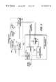
- FIG. 2is a block diagram of a audio/video decompression apparatus embodying the present invention.
- FIG. 3is a block diagram of apparatus for providing the receiver system clock signal having substantially the same rate as the system clock of the compression apparatus.
- FIG. 4is a flow chart of the operation of the FIG. 2 apparatus.
- FIG. 5is a block diagram of alternative muting circuitry which may be implemented in the FIG. 2 apparatus.
- FIG. 1illustrates a typical system in which the invention may be practiced, which system is a compressed digital video signal transmission arrangement.
- video signal from a source 10is applied to a video signal compression element 11 which may include a motion compensated predictive encoder utilizing discrete cosine transforms.
- Compressed video signal from the element 11is coupled to a formatter 12 .
- the formatterarranges the compressed video signal and other ancillary data according to some signal protocol such as MPEG, a standard developed by the International Organization for Standardization (Organization Internationale De Normalisation).
- the standardized signalis applied to a transport processor 13 , which divides the signal into packets of data and adds certain overhead to provide some noise immunity for the transmission purposes.
- the transport packetswhich normally occur at a non-uniform rate are applied to a rate buffer 14 which provides output data at a relatively constant rate conducive to efficient use of a relatively narrow bandwidth transmission channel.
- the buffered datais coupled to a modem 15 which performs the signal transmission.
- a system clock 22provides clocking signal to operate much of the apparatus, at least including the transport processor. This clock will operate at a fixed frequency such as 27 MHz for example. As shown herein, however, it is used to generate timing information.
- the system clockis coupled to the clock input of a counter 23 which may be arranged to count modulo 230 , for example.
- the count values output by the counterare applied to two latches 24 and 25 .
- the latch 24is conditioned by the video source to latch count values on the occurrence of respective frame intervals. These count values are denoted presentation time stamps, PTS's, and are included in the compressed video signal stream by the formatter 12 , and are used by the receiver to provide lip-synchronization of associated audio and video information.
- the latch 25is conditioned by the transport processor 13 (or the system controller 21 ) to latch count values according to a predetermined schedule. These count values are denoted system clock references, SCR's, and are embedded as auxiliary data within respective auxiliary transport packets.
- Audio signal associated with the video signal from source 10is applied to an audio signal compressor 18 .
- the compressor 18provides frame sampling pulses (independent of video frames) to control a latch 19 . Responsive to the sampling pulses, the latch 19 captures count values provided by the counter 23 . These latched values correspond to audio presentation time stamps PTS aud .
- the PTS audare incorporated in the compressed audio signal provided by the compressor 18 .
- the compressed audio signalis coupled to a transport processor 17 which divides the signal into packets of data and adds certain overhead to provide some noise immunity for transmission purposes.
- the audio transport packets provided by the processor 17are coupled to a multiplexor 16 which time division multiplexes the audio and video transport packets. In the figure, separate transport processors are shown in the audio and video signal processing channels. For systems wherein the data rate is moderate, the functions of the two transport processors and the multiplexor 16 may subsumed in a single transport processor.
- the system controller 21is a variable state machine programmed to coordinate the various processing elements. Note that the controller 21 , the compressors 11 and 18 , the transport processors 13 and 17 , and the rate buffer 14 may or may not operate synchronously via a common clocking arrangement as long as proper handshaking is provided between processing elements. However, the two compressors both derive PTS values from the same reference counter 23 , thus a precise timing relationship between the two compressed signals is provided in the compressed output signal.
- FIG. 2illustrates an exemplary receiver apparatus embodying the invention wherein the modem 200 performs the inverse function of the modem 15 and the rate buffer 206 performs, in effect, the inverse function of the rate buffer 14 .
- An inverse transport processor 202divides respective transport packets by service and allocates the respective packet payloads differing memory blocks in the rate buffer 206 . In so doing the respective transport packet signal payloads are separated from the auxiliary data, with the auxiliary data applied to the system controller 210 .
- a separate transport processormay be included in each processing channel and arranged to recognize and process only data associated with the respective channels.
- Compressed video data from the rate buffer 206is passed to the video decompressor 214 .
- the rate buffer 206accepts compressed video data at a bursty or inconsistent rate, and provides data on demand to the decompressor 214 .
- the decompressorresponsive to the compressed video signal, generates non-compressed video signal for display or for storage etc., in appropriate display or storage devices (not shown).
- Compressed audio data from the inverse transport processor 202is applied to the rate buffer 206 , which provides compressed audio signal according to the system protocol to the audio decompressor 212 .
- the decompressor 212responsive to the compressed audio signal generates non-compressed audio signal for reproduction or for storage etc., in appropriate speakers or storage devices (not shown).
- the inverse processor 202also provides SCR's from the auxiliary transport data, and control signals to a system clock generator 208 .
- the clock generatorresponsive to these signals generates a system clock signal synchronous with at least the transport processor operation. This system clock signal is applied to the receiver system controller 210 to control the timing of appropriate processing elements.
- FIG. 3illustrates details of an exemplary clock regenerator 208 .
- Data from the receiver modem 200is coupled to the inverse transport processor 202 ′, including an auxiliary packet detector 31 .
- the inverse transport processor 202 ′separates transport header data from the respective transport packet payloads. Responsive to the transport header data, the processor 202 ′ demultiplexes payloads of the desired associated audio and video program components and payloads of associated auxiliary data.
- the audio video and auxiliary payloadsare written to separate memory blocks of the rate buffer 208
- the respective memory blocksare each operated as first-in-first-out memories or FIFO's, writing data when it is available from the modem and reading data when it is demanded by the corresponding component signal processor (not shown).
- SCR's present in particular auxiliary packetsare routed and stored in a memory element, 34 .
- An auxiliary packet detector 31which may be a matched filter arranged to recognize the code words designating an auxiliary transport packet containing a SCR, produces a control pulse on the occurrence of transport packets containing such data.
- the control pulseis utilized to capture and store within a latch 35 , the count value currently exhibited by the local counter 36 at a time precisely related to the time of detection.
- the local counter 36is arranged to count pulses provided by a voltage controlled oscillator 37 .
- the counter 36is arranged to count modulo M which may be, but is not necessarily, the same number as its counterpart counter in the encoder (counter 23 ). If M differs from N the difference may be accommodated in the error equation.
- the voltage controlled oscillator 37is controlled by a low pass filtered error signal provided by a clock controller 39 .
- the error signalis generated in the following fashion. Let the SCR arriving at time n be designated SCR n and the local count value concurrently captured in the latch 35 be designated LCR n .
- the clock controllerreads the successive values of SCR's and LCR's and forms an error signal E proportional to the differences
- the error signal Eis utilized to condition the voltage controlled oscillator 37 to frequency tending to equalize the differences. As indicated previously, negative differences exhibited due to modulo counter wrap around, may be ignored.
- the error signal produced by the clock controller 39may be in the form of a pulse width modulated signal, which may be rendered into an analog error signal by implementing the low pass filter 38 in analog components.
- LTELong term error
- SCR 0 and LCR 0are for example the first occurring SCR and the corresponding latched value of the receiver counter.
- the error signals E and LTEwill vary in discrete steps. As such, once the system is “synchronized” the error signal will dither one unit about the null point.
- the preferred method of synchronizationis to initiate control of the voltage controlled oscillator using the error signal E until a one unit dither occurs in the error signal E, and then to switch to the use of the long term error signal LTE to control the voltage controlled oscillator.
- the system clock signal provided by the VCXO 37may be utilized to operate at least the transport processor and rate buffers. Since it is synchronized at least in frequency with the encoder system clock, the possibility of rate buffer overflow or underflow due to clock timing errors is substantially non-existent.
- a presentation time stamp PTS vidis included in the compressed video signal associated with predetermined video data.
- the PTS vidis indicative of the relative time that the associated video is to be displayed.
- the compressed audio signalincludes presentation time stamps PTS aud associated with audio to be reproduced at times related to the respective PTS aud .
- the PTS aud and PTS vidmay not be compared directly to provide A/V synchronization because the respective samples were determined at different instants.
- the respective PTS valuesare compared to a continuous time base which is the receiver clock provided by the VCXO 37 . (This is done by sampling local count values LCR generated by the system clock 208 to capture local time stamps.
- the LCRWhen data associated with a corresponding PTS is presented, the LCR is sampled.
- the audio decompressor 212issues a PTS aud when a respective audio frame is output for reproduction. At these times a control signal conditions the latch 220 to sample the LCR, the values of which will be designated LAS, for local audio stamp.
- the video decompressorprovides a video frame for display, it provides a PTS vid and a control pulse to condition a latch 222 to store the current value of the LCR.
- These LCR valuesare designated LVS for local video stamps.
- the LAS and the corresponding PTS audare coupled to respective input terminals of a subtracter 218 which develops the signal ⁇ A-PTS according to the relation;
- the LVS and the corresponding PTSvidare coupled to respective input terminals of the subtracter 217 which develops the signal ⁇ V-PTS according to the relation;
- V-PTSPTS vid ⁇ LVS.
- the signals ⁇ V-PTS and ⁇ A-PTSare coupled to respective input terminals of a further subtracter, 219 , which develops an A/V synchronization error signal ERR PTS according to the relation;
- ERR PTS⁇ V-PTS ⁇ A-PTS
- Synchronization of the audio and videorequires that the A/V synchronization error be driven to zero.
- the difference in the values of the corresponding audio and video PTS'sequals the time, in units of the local reference, between the occurrence of the corresponding PTS's, the audio and video signal will be in synchronization.
- Two mechanismsmay be used to adjust the A/V synchronization based upon the error signal ERR PTS ; skips and repeats of data sections and conversion clock deviation. Skipping fixed intervals or “frames” of audio advances the audio data stream by a fixed interval relative to the video signal. Repeating (or muting without consuming data) delays the audio data stream by fixed intervals relative to the video signal. Skipping and repeating audio frames is audible under many conditions, and therefore is only utilized for coarse adjustment of synchronization. Even so, brief skipping or repeating may be preferable to discernible audio/video synchronization errors.
- the error signal ERR PTSis applied to a filter and processing element 216 .
- a filter function thereinsmoothes the signal ERR PTS to minimize aberrant effects that might otherwise be generated by signal noise.
- the processing portion of element 216examines the smoothed error signal and determines whether a skip/repeat of audio should be utilized to effect coarse synchronization of the audio and video signals and/or whether an adjustment to the audio processing frequency should be utilized to effect fine synchronization, or whether neither should be performed. If a coarse synchronization adjustment is determined to be necessary, the processor 216 provides a control signal (S/R) to the audio decompressor 212 to condition the decompressor to skip or repeat the current decompressed audio frame. Alternatively, or in addition to the coarse adjustment, if a fine adjustment is determined to be necessary, the processor 216 provides a control signal to the audio time base 215 to adjust the frequency of the audio processing clock signal.
- S/Rcontrol signal
- the processing algorithmis detailed in the flow chart of FIG. 4 .
- the systemmonitors ( 401 ) the audio decompressor for the occurrence of a PTS aud and if a PTS aud is detected it is read at step 403 and a local clock reference LAS is captured and stored. If a PTS aud has not occurred, the system monitors the video compressor for a PTS vid ( 402 ). If a PTS vid has occurred, the PTS vid is read and a local clock reference LVS is captured and stored. When both a PTS aud and a PTS vid have been read the ERR PTS is calculated at step 405 according to the equation;
- the magnitude of the error signalis examined ( 420 ) to determine if it is greater than a predetermined maximum value dependent upon the size of delay storage memory in the audio decoder. If the error is greater than this maximum, a check is made at step 421 to determine how long this condition has existed. If it is greater than a predetermined, or selectable, time of N seconds, then the synchronization process is suspended ( 422 ). If the condition has existed for less than N seconds, the synchronization continues at step 406 . Because the skip and repeat functions react differently with respect to audio memory, the threshold of N seconds may be different for positive and negative values of the error signal.
- the magnitude of the error signalis examined at step 406 to determine if it is greater than, for example, one half an audio frame interval. If it is greater than one half an audio frame interval, the error signal is checked for polarity at step 407 . If the polarity is positive, the current audio frame is repeated ( 409 ). If it is negative the current audio frame is skipped at step 408 . After skipping or repeating a frame the system iterates back to the start position to wait for the next occurrence of PTS's.
- the erroris examined at step 410 to determine if it is greater than zero. If the error is greater than zero, the error is checked at step 412 to determine if it is less than the previous error signal. If it is less than the previous error signal, this is an indication that the system is converging toward synchronization, and the synchronization control parameters are not changed. The system returns to the start position to wait for the next PTS's. Conversely, if the error has increased over the previous error signal, the audio system processing clock is adjusted at step 414 to lessen its frequency.
- step 410if the error is less than zero (negative), it is checked at step 411 to determine whether it is greater than the previous error signal. If it is greater than the previous error signal, this is also an indication that the system is converging toward synchronization, and the synchronization control parameters are not changed. Alternatively if the current error signal is less than the previous error signal the system is moving further out of synchronization and the audio processing clock frequency is increased at step 413 . After processing steps 412 and 413 the system returns to wait for the next occurrence of PTS's. It will be noted in this example, that the system performs only coarse adjustments via skipping or repeating audio frames until the A/V synchronization error is reduced to less than one half an audio frame interval.
- the filtered error signalis compared against a predetermined threshold related to the size of respective audio frames. If the error signal is less than the threshold, indicative that the audio-video timing error is less than an audio frame, the error signal is coupled to the audio time base circuit 215 , wherein it is utilized to adjust the frequency of the audio signal processing (decompression) clock.
- the error signalmay be divided by the audio frame interval to determine the number of audio frames that the audio and video signal are misaligned. The integer portion of the quotient is applied to the audio decompressor to condition the audio decompressor to skip or repeat that number of audio frames. The polarity of the error signal will determine whether audio frames should be skipped or repeated. Nominally the compressed data is arranged in a buffer memory prior to being decoded, hence skipping or repeating audio frames is a simple matter of controllably enabling the memory read/write commands.
- the fractional portion of the quotientis coupled to the audio time base circuit 215 , where it is utilized to adjust the audio processing clock to fine tune the A/V synchronization.
- the rate of production of audio PTS'sis proportional to the processing speed of the audio decompressor.
- the processing speed of the audio decompressoris directly proportional to the frequency of the clock signal used to operate the audio decompressor. If the clock frequency of the audio decompressor is independent of the clock used to operate the video decompressor, and is finely adjustable, then the relative rate of occurrence of the audio and video PTS's can be adjusted and the A/V finely synchronized.
- Decompressed audio signalis coupled to a digital-to-analog converter (DAC) 227 .
- Analog output signal from the DAC 227is coupled to further analog processing circuitry (not shown) via a resistor 228 .
- the conduction path of a muting transistor 229is coupled between the resistor 228 and ground potential.
- the control electrode of the transistoris coupled to an output connection of a threshold detector 225 . A positive control voltage of greater than one V be will condition the transistor 229 to clamp the audio output signal from DAC 227 to ground potential, thereby muting the audio signal.
- a compressed audio signalwill include a plurality of components such as a left signal, a right signal, etc.
- FIG. 2shows only one audio output for simplicity, however each audio channel will include a muting-circuit controlled by a common muting control signal.
- Muting the audio signalmay be performed for various reasons, not the least of which is loss of lip-sync.
- the current apparatusis unique in that it mutes audio based on lip-sync error.
- a human viewerwill notice lip-sync errors of ⁇ 20 ms or +40 ms.
- audiois muted if the lip-sync error exceeds approximately 13 ms.
- the 13 ms thresholdwas chosen to be less than 20 ms but greater than one-half an MPEG 1 , layer 11 audio frame (which is 24 ms).
- the thresholdwas selected to be slightly greater than one half the audio frame because with A/V synchronizing frame skips and repeats, an initial synchronizing state at a half frame (12 ms) is possible, and a threshold of approximately 12 ms or less could result in synchronized, but muted audio.
- a threshold equivalent to one half frameproduces intermittent muting due to minor fluctuation in calculated lip-sync errors due to clock and PTS strobe sampling uncertainties.
- the muting control signalis generated by the threshold detector 225 , which monitors the A/V synchronization error signal available from the subtracter 219 . When the error signal exceeds a value corresponding to 13 ms, a muting control value is generated. To preclude noise or other impulsive conditions from causing generation of false muting signals, the error signals from the subtracter 219 may be low pass filtered before application to the threshold detector 225 .
- Dashed arrows emanating from the detector 225 and terminating on the DAC 227 and the audio decompressor 212indicate alternative muting possibilities.
- the muting control signalmay be designed for disabling the output of the DAC 227 or the output of the decompressor 212 . In either instance the disabling function should be arranged to condition the respective processing element to output a signal amplitude value midway between the output signal dynamic range.
- the FIG. 2 arrangementalso indicates that video muting (or blanking) may be implemented via control of the video DAC 224 .
- Muting controlmay be suspended when synchronization is too far from convergence.
- Detector 225may be configured to compare the error signal with a maximum threshold, and suspend muting if the error signal exceeds this threshold, or if it exceeds the maximum threshold for a predetermined time, or simply if muting occurs for longer than a predetermined interval.
- a muting suspension controlmay also be provided by the processor 216 at step 422 .
- FIG. 5illustrates an alternative muting arrangement.
- the skip/repeat (S/R) signal generated by the filter 216is used as a primary muting control.
- This signalis coupled to the muting circuitry via an OR gate 230 and an AND gate 233 .
- the AND gate 233is used as a mute override responsive to a SUSPEND MUTE signal from the processor 216 .
- AND gate 233is really symbolic in nature, because suspension of muting will likely be effected within the mute control signal generator itself.
- a threshold detector, 231may be included to monitor the audio time base fine control signal and generate a secondary muting control signal. This secondary control signal is also coupled to the muting circuitry via the OR gate 230 .
- the apparatus of FIG. 5illustrates a further possible muting circuit, consisting of an AND gate, 226 , to selectively couple the decompressed audio signal from the decompressor 212 to the DAC 227 .
- Nominally audio signalsare bipolar (AC) and swing about zero value.
- the AND gatewhen in the decoupled state, desirably outputs zero value which is the middle of the signal dynamic range.
- a further threshold detector, 232may be included to monitor the error signal generated by the clock controller 39 shown in FIG. 3 .
- the threshold detector, 232generates a muting control signal when the error signal produced by the controller represents a frequency deviation from the locked condition by, for example, 0.2.
- This muting control signalis coupled to the OR gate 230 to effect audio muting until the system clock is substantially synchronized with the corresponding encoding system clock.
- detection apparatusmay be coupled to measure the frequency deviation of the audio time base 215 for generating a further muting signal which may be ORed in the gate 230 .
Landscapes
- Engineering & Computer Science (AREA)
- Multimedia (AREA)
- Signal Processing (AREA)
- Compression Or Coding Systems Of Tv Signals (AREA)
Abstract
Description
Claims (11)
Priority Applications (13)
| Application Number | Priority Date | Filing Date | Title |
|---|---|---|---|
| US09/358,070US6583821B1 (en) | 1999-07-16 | 1999-07-21 | Synchronizing apparatus for a compressed audio/video signal receiver |
| CA2313979ACA2313979C (en) | 1999-07-21 | 2000-07-06 | Synchronizing apparatus for a compressed audio/video signal receiver |
| EP00114771AEP1071290A3 (en) | 1999-07-21 | 2000-07-10 | Synchronizing apparatus for a compressed audio/video signal receiver |
| JP2000217749AJP4903930B2 (en) | 1999-07-21 | 2000-07-18 | Signal processing device |
| RU2000119032/09ARU2262211C2 (en) | 1999-07-21 | 2000-07-19 | Synchronizing device for receiver of compressed audio and image signal |
| MYPI20003284AMY120627A (en) | 1999-07-21 | 2000-07-19 | Synchronizing apparatus for a compressed audio/video signal receiver. |
| KR1020000041591AKR100805757B1 (en) | 1999-07-21 | 2000-07-20 | Synchronization device and method for compressed audio / video signal receiver |
| BR0003012-0ABR0003012A (en) | 1999-07-21 | 2000-07-20 | Synchronization device for a compressed audio / video signal receiver |
| MXPA00007132AMXPA00007132A (en) | 1999-07-21 | 2000-07-20 | Synchronizing apparatus for a compressed audio/video signal receiver. |
| TR2000/02156ATR200002156A2 (en) | 1999-07-21 | 2000-07-21 | Synchronization device for compressed audio / video signal receiver |
| CNB001216635ACN1160696C (en) | 1999-07-21 | 2000-07-21 | Synchronization device and method for compressed audio/video signal receiver |
| HK01104972.3AHK1034348B (en) | 1999-07-21 | 2001-07-16 | Synchronizing apparatus and method for a compressed audio/video signal receiver |
| KR1020070102174AKR20070105947A (en) | 1999-07-21 | 2007-10-10 | Synchronization device and method for compressed audio / video signal receiver |
Applications Claiming Priority (2)
| Application Number | Priority Date | Filing Date | Title |
|---|---|---|---|
| US14434099P | 1999-07-16 | 1999-07-16 | |
| US09/358,070US6583821B1 (en) | 1999-07-16 | 1999-07-21 | Synchronizing apparatus for a compressed audio/video signal receiver |
Publications (1)
| Publication Number | Publication Date |
|---|---|
| US6583821B1true US6583821B1 (en) | 2003-06-24 |
Family
ID=26841918
Family Applications (1)
| Application Number | Title | Priority Date | Filing Date |
|---|---|---|---|
| US09/358,070Expired - LifetimeUS6583821B1 (en) | 1999-07-16 | 1999-07-21 | Synchronizing apparatus for a compressed audio/video signal receiver |
Country Status (1)
| Country | Link |
|---|---|
| US (1) | US6583821B1 (en) |
Cited By (34)
| Publication number | Priority date | Publication date | Assignee | Title |
|---|---|---|---|---|
| US20020012398A1 (en)* | 1999-12-20 | 2002-01-31 | Minhua Zhou | Digital still camera system and method |
| US20020027880A1 (en)* | 2000-06-13 | 2002-03-07 | Altigen Communications, Inc. | Packetized communications apparatus and method |
| US20020140858A1 (en)* | 2001-03-29 | 2002-10-03 | Winbond Electronics Corp. | Synchronous decoding method for AV packets |
| US20020191107A1 (en)* | 2001-06-14 | 2002-12-19 | Sony Corporation | Start/stop audio encoder apparatus and method for synchronizing digital audio and video signals |
| US20030170007A1 (en)* | 2002-03-05 | 2003-09-11 | Kazushi Namatame | Audio reproducing apparatus |
| US20030231871A1 (en)* | 2002-05-31 | 2003-12-18 | Kabushiki Kaisha Toshiba | Audio reproducing apparatus and audio reproduction control method for use in the same |
| US20040041946A1 (en)* | 2002-08-27 | 2004-03-04 | Gries Patrick J. | Method and apparatus for decoding audio and video information |
| US20040062566A1 (en)* | 2002-09-27 | 2004-04-01 | Keiji Kato | Image forming apparatus |
| US20040080671A1 (en)* | 2002-06-14 | 2004-04-29 | Duane Siemens | Method and circuit for generating time stamp data from an embedded-clock audio data stream and a video clock |
| US20040117191A1 (en)* | 2002-09-12 | 2004-06-17 | Nambi Seshadri | Correlating video images of lip movements with audio signals to improve speech recognition |
| US20040226040A1 (en)* | 2000-05-25 | 2004-11-11 | Jacques Thibon | Device and method for synchronising broadcast audio-visual programmes and complementary data |
| US20050174485A1 (en)* | 2004-02-09 | 2005-08-11 | Brad Delanghe | Method and system for 3D comb synchronization and alignment of standard and non-standard video signals |
| DE102004017215A1 (en)* | 2004-04-05 | 2005-10-20 | Sennheiser Electronic | Audio-visual system for e.g. television set, has delay adjusting unit that adjusts delay of video data, such that video data is delayed in dependence of delay that is caused in transferred audio data by audio transmission line |
| MY120627A (en)* | 1999-07-21 | 2005-11-30 | Thomson Licensing Sa | Synchronizing apparatus for a compressed audio/video signal receiver. |
| US20050281255A1 (en)* | 2004-06-18 | 2005-12-22 | Trevor Davies | Maintaining synchronization of streaming audio and video using internet protocol |
| US20060034375A1 (en)* | 1998-10-09 | 2006-02-16 | Snell & Wilcox Limited | Data compression unit control for alignment of output signal |
| US20060095623A1 (en)* | 2003-05-28 | 2006-05-04 | Yutaka Nio | Digital interface receiver apparatus |
| US20060140280A1 (en)* | 2003-06-12 | 2006-06-29 | Sony Corporation | Device for recording video data and audio data |
| US20060161945A1 (en)* | 2005-01-14 | 2006-07-20 | Samsung Electronics Co., Ltd. | Method for informing video receiving delay and broadcast receiving apparatus thereof |
| US20060168524A1 (en)* | 2003-03-19 | 2006-07-27 | Shinichi Saeki | Data processing device |
| WO2006101504A1 (en)* | 2004-06-22 | 2006-09-28 | Sarnoff Corporation | Method and apparatus for measuring and/or correcting audio/visual synchronization |
| US20060268995A1 (en)* | 2005-05-31 | 2006-11-30 | Kabushiki Kaisha Toshiba | Video signal processing device and image quality correcting method for the same |
| US20070165838A1 (en)* | 2006-01-13 | 2007-07-19 | Microsoft Corporation | Selective glitch detection, clock drift compensation, and anti-clipping in audio echo cancellation |
| US20070247550A1 (en)* | 2006-04-21 | 2007-10-25 | Alan Plaunt | Systems and Methods for Synchronizing Audio and Video Data Signals |
| US20090110364A1 (en)* | 2007-10-29 | 2009-04-30 | Manabu Kuroda | Reproduction apparatus and reproduction method |
| US20090110370A1 (en)* | 2007-10-24 | 2009-04-30 | Hideaki Shibata | Audio/video synchronous playback device |
| US20090207763A1 (en)* | 2008-02-15 | 2009-08-20 | Microsoft Corporation | Voice switching for voice communication on computers |
| US20090316881A1 (en)* | 2008-06-20 | 2009-12-24 | Microsoft Corporation | Timestamp quality assessment for assuring acoustic echo canceller operability |
| US20120102538A1 (en)* | 2010-10-22 | 2012-04-26 | Stmicroelectronics (Grenoble) Sas | Methods and apparatus for decoding multiple independent audio streams using a single audio decoder |
| US20130229575A1 (en)* | 2012-03-02 | 2013-09-05 | Mstar Semiconductor, Inc. | Digital TV Data Processing Method and System Thereof |
| US20130342632A1 (en)* | 2012-06-25 | 2013-12-26 | Chi-Chung Su | Video conference apparatus and method for audio-video synchronization |
| US9300927B2 (en) | 2006-06-13 | 2016-03-29 | Koninklijke Philips N.V. | Fingerprint, apparatus, method for identifying and synchronizing video |
| US9565426B2 (en) | 2010-11-12 | 2017-02-07 | At&T Intellectual Property I, L.P. | Lip sync error detection and correction |
| US9729762B2 (en) | 2010-10-15 | 2017-08-08 | Thomson Licensing | Method for synchronizing multimedia flows and corresponding device |
Citations (5)
| Publication number | Priority date | Publication date | Assignee | Title |
|---|---|---|---|---|
| US5430485A (en)* | 1993-09-30 | 1995-07-04 | Thomson Consumer Electronics, Inc. | Audio/video synchronization in a digital transmission system |
| US5467139A (en) | 1993-09-30 | 1995-11-14 | Thomson Consumer Electronics, Inc. | Muting apparatus for a compressed audio/video signal receiver |
| US5565923A (en)* | 1993-05-13 | 1996-10-15 | Rca Licensing Corporation | Apparatus for formatting a digital signal to include multiple time stamps for system synchronization |
| US6130987A (en)* | 1997-10-02 | 2000-10-10 | Nec Corporation | Audio-video synchronous playback apparatus |
| US6188731B1 (en)* | 1997-05-30 | 2001-02-13 | Samsung Electronics Co., Ltd. | Apparatus and method for synchronizing audio/video signal |
- 1999
- 1999-07-21USUS09/358,070patent/US6583821B1/ennot_activeExpired - Lifetime
Patent Citations (5)
| Publication number | Priority date | Publication date | Assignee | Title |
|---|---|---|---|---|
| US5565923A (en)* | 1993-05-13 | 1996-10-15 | Rca Licensing Corporation | Apparatus for formatting a digital signal to include multiple time stamps for system synchronization |
| US5430485A (en)* | 1993-09-30 | 1995-07-04 | Thomson Consumer Electronics, Inc. | Audio/video synchronization in a digital transmission system |
| US5467139A (en) | 1993-09-30 | 1995-11-14 | Thomson Consumer Electronics, Inc. | Muting apparatus for a compressed audio/video signal receiver |
| US6188731B1 (en)* | 1997-05-30 | 2001-02-13 | Samsung Electronics Co., Ltd. | Apparatus and method for synchronizing audio/video signal |
| US6130987A (en)* | 1997-10-02 | 2000-10-10 | Nec Corporation | Audio-video synchronous playback apparatus |
Cited By (58)
| Publication number | Priority date | Publication date | Assignee | Title |
|---|---|---|---|---|
| US20060034375A1 (en)* | 1998-10-09 | 2006-02-16 | Snell & Wilcox Limited | Data compression unit control for alignment of output signal |
| MY120627A (en)* | 1999-07-21 | 2005-11-30 | Thomson Licensing Sa | Synchronizing apparatus for a compressed audio/video signal receiver. |
| US6754279B2 (en)* | 1999-12-20 | 2004-06-22 | Texas Instruments Incorporated | Digital still camera system and method |
| US20020012398A1 (en)* | 1999-12-20 | 2002-01-31 | Minhua Zhou | Digital still camera system and method |
| US7015972B2 (en)* | 2000-05-25 | 2006-03-21 | Thomson Licensing | Device and method for synchronizing broadcast audio-visual programs and complementary data |
| US20040226040A1 (en)* | 2000-05-25 | 2004-11-11 | Jacques Thibon | Device and method for synchronising broadcast audio-visual programmes and complementary data |
| US20020027880A1 (en)* | 2000-06-13 | 2002-03-07 | Altigen Communications, Inc. | Packetized communications apparatus and method |
| US6909709B2 (en)* | 2000-06-13 | 2005-06-21 | Altigen Communications, Inc. | Packetized communications apparatus and method |
| US6697121B2 (en)* | 2001-03-29 | 2004-02-24 | Winbond Electronics Corp. | Synchronous decoding method for AV packets |
| US20020140858A1 (en)* | 2001-03-29 | 2002-10-03 | Winbond Electronics Corp. | Synchronous decoding method for AV packets |
| US20020191107A1 (en)* | 2001-06-14 | 2002-12-19 | Sony Corporation | Start/stop audio encoder apparatus and method for synchronizing digital audio and video signals |
| US7012650B2 (en)* | 2001-06-14 | 2006-03-14 | Sony Corporation | Start/stop audio encoder apparatus and method for synchronizing digital audio and video signals |
| US20030170007A1 (en)* | 2002-03-05 | 2003-09-11 | Kazushi Namatame | Audio reproducing apparatus |
| US7308188B2 (en)* | 2002-03-05 | 2007-12-11 | D & M Holdings Inc. | Audio reproducing apparatus |
| US7228059B2 (en)* | 2002-05-31 | 2007-06-05 | Kabushiki Kaisha Toshiba | Audio reproducing apparatus and audio reproduction control method for use in the same |
| US20030231871A1 (en)* | 2002-05-31 | 2003-12-18 | Kabushiki Kaisha Toshiba | Audio reproducing apparatus and audio reproduction control method for use in the same |
| US7283566B2 (en)* | 2002-06-14 | 2007-10-16 | Silicon Image, Inc. | Method and circuit for generating time stamp data from an embedded-clock audio data stream and a video clock |
| US20040080671A1 (en)* | 2002-06-14 | 2004-04-29 | Duane Siemens | Method and circuit for generating time stamp data from an embedded-clock audio data stream and a video clock |
| US20040041946A1 (en)* | 2002-08-27 | 2004-03-04 | Gries Patrick J. | Method and apparatus for decoding audio and video information |
| US6850284B2 (en)* | 2002-08-27 | 2005-02-01 | Motorola, Inc. | Method and apparatus for decoding audio and video information |
| US20040117191A1 (en)* | 2002-09-12 | 2004-06-17 | Nambi Seshadri | Correlating video images of lip movements with audio signals to improve speech recognition |
| US7587318B2 (en)* | 2002-09-12 | 2009-09-08 | Broadcom Corporation | Correlating video images of lip movements with audio signals to improve speech recognition |
| US20040062566A1 (en)* | 2002-09-27 | 2004-04-01 | Keiji Kato | Image forming apparatus |
| US7567746B2 (en)* | 2003-03-19 | 2009-07-28 | Panasonic Corporation | Data processing device |
| US20060168524A1 (en)* | 2003-03-19 | 2006-07-27 | Shinichi Saeki | Data processing device |
| US20060095623A1 (en)* | 2003-05-28 | 2006-05-04 | Yutaka Nio | Digital interface receiver apparatus |
| US7826562B2 (en)* | 2003-05-28 | 2010-11-02 | Panasonic Corporation | Digital interface receiver apparatus |
| US7738772B2 (en)* | 2003-06-12 | 2010-06-15 | Sony Corporation | Apparatus and method for synchronizing video data and audio data having different predetermined frame lengths |
| US20060140280A1 (en)* | 2003-06-12 | 2006-06-29 | Sony Corporation | Device for recording video data and audio data |
| US7405769B2 (en)* | 2004-02-09 | 2008-07-29 | Broadcom Corporation | Method and system for 3D comb synchronization and alignment of standard and non-standard video signals |
| US20050174485A1 (en)* | 2004-02-09 | 2005-08-11 | Brad Delanghe | Method and system for 3D comb synchronization and alignment of standard and non-standard video signals |
| DE102004017215A1 (en)* | 2004-04-05 | 2005-10-20 | Sennheiser Electronic | Audio-visual system for e.g. television set, has delay adjusting unit that adjusts delay of video data, such that video data is delayed in dependence of delay that is caused in transferred audio data by audio transmission line |
| US7400653B2 (en) | 2004-06-18 | 2008-07-15 | Dolby Laboratories Licensing Corporation | Maintaining synchronization of streaming audio and video using internet protocol |
| US20050281255A1 (en)* | 2004-06-18 | 2005-12-22 | Trevor Davies | Maintaining synchronization of streaming audio and video using internet protocol |
| WO2006101504A1 (en)* | 2004-06-22 | 2006-09-28 | Sarnoff Corporation | Method and apparatus for measuring and/or correcting audio/visual synchronization |
| US20060161945A1 (en)* | 2005-01-14 | 2006-07-20 | Samsung Electronics Co., Ltd. | Method for informing video receiving delay and broadcast receiving apparatus thereof |
| US20060268995A1 (en)* | 2005-05-31 | 2006-11-30 | Kabushiki Kaisha Toshiba | Video signal processing device and image quality correcting method for the same |
| US20070165838A1 (en)* | 2006-01-13 | 2007-07-19 | Microsoft Corporation | Selective glitch detection, clock drift compensation, and anti-clipping in audio echo cancellation |
| US8295475B2 (en) | 2006-01-13 | 2012-10-23 | Microsoft Corporation | Selective glitch detection, clock drift compensation, and anti-clipping in audio echo cancellation |
| US20070247550A1 (en)* | 2006-04-21 | 2007-10-25 | Alan Plaunt | Systems and Methods for Synchronizing Audio and Video Data Signals |
| US8179476B2 (en)* | 2006-04-21 | 2012-05-15 | Evertz Microsystems Ltd. | Systems and methods for synchronizing audio and video data signals |
| US9300927B2 (en) | 2006-06-13 | 2016-03-29 | Koninklijke Philips N.V. | Fingerprint, apparatus, method for identifying and synchronizing video |
| US20090110370A1 (en)* | 2007-10-24 | 2009-04-30 | Hideaki Shibata | Audio/video synchronous playback device |
| US8301018B2 (en)* | 2007-10-24 | 2012-10-30 | Panasonic Corporation | Audio/video synchronous playback device |
| US20090110364A1 (en)* | 2007-10-29 | 2009-04-30 | Manabu Kuroda | Reproduction apparatus and reproduction method |
| US20090207763A1 (en)* | 2008-02-15 | 2009-08-20 | Microsoft Corporation | Voice switching for voice communication on computers |
| US8380253B2 (en) | 2008-02-15 | 2013-02-19 | Microsoft Corporation | Voice switching for voice communication on computers |
| US8934945B2 (en) | 2008-02-15 | 2015-01-13 | Microsoft Corporation | Voice switching for voice communication on computers |
| US20090316881A1 (en)* | 2008-06-20 | 2009-12-24 | Microsoft Corporation | Timestamp quality assessment for assuring acoustic echo canceller operability |
| US8369251B2 (en)* | 2008-06-20 | 2013-02-05 | Microsoft Corporation | Timestamp quality assessment for assuring acoustic echo canceller operability |
| US9729762B2 (en) | 2010-10-15 | 2017-08-08 | Thomson Licensing | Method for synchronizing multimedia flows and corresponding device |
| US8613038B2 (en)* | 2010-10-22 | 2013-12-17 | Stmicroelectronics International N.V. | Methods and apparatus for decoding multiple independent audio streams using a single audio decoder |
| US20120102538A1 (en)* | 2010-10-22 | 2012-04-26 | Stmicroelectronics (Grenoble) Sas | Methods and apparatus for decoding multiple independent audio streams using a single audio decoder |
| US9565426B2 (en) | 2010-11-12 | 2017-02-07 | At&T Intellectual Property I, L.P. | Lip sync error detection and correction |
| US10045016B2 (en) | 2010-11-12 | 2018-08-07 | At&T Intellectual Property I, L.P. | Lip sync error detection and correction |
| US20130229575A1 (en)* | 2012-03-02 | 2013-09-05 | Mstar Semiconductor, Inc. | Digital TV Data Processing Method and System Thereof |
| US20130342632A1 (en)* | 2012-06-25 | 2013-12-26 | Chi-Chung Su | Video conference apparatus and method for audio-video synchronization |
| US8830290B2 (en)* | 2012-06-25 | 2014-09-09 | Hon Hai Precision Industry Co., Ltd. | Video conference apparatus and method for audio-video synchronization |
Similar Documents
| Publication | Publication Date | Title |
|---|---|---|
| US6583821B1 (en) | Synchronizing apparatus for a compressed audio/video signal receiver | |
| CA2147013C (en) | Muting apparatus for a compressed audio/video signal receiver | |
| JP4382736B2 (en) | Device for synchronizing audio and video signals | |
| US5703877A (en) | Acquisition and error recovery of audio data carried in a packetized data stream | |
| CN100515091C (en) | Device and method for synchronization of compressed video signal receiving system | |
| EP0624982B1 (en) | Apparatus and method for compressing video signals, and synchronising apparatus | |
| EP0731615B1 (en) | Video decoding device for decoding video data in synchronism with a system clock | |
| KR20070105947A (en) | Synchronization device and method for compressed audio / video signal receiver | |
| KR100224099B1 (en) | Synchronizer and Method of Audio / Video Signal | |
| HK1034348B (en) | Synchronizing apparatus and method for a compressed audio/video signal receiver | |
| JPH08280008A (en) | Method and device for encoding |
Legal Events
| Date | Code | Title | Description |
|---|---|---|---|
| AS | Assignment | Owner name:THOMSON CONSUMER ELECTRONICS, INC., INDIANA Free format text:ASSIGNMENT OF ASSIGNORS INTEREST;ASSIGNOR:DURAND, FRANCK MICHEL;REEL/FRAME:010126/0742 Effective date:19990716 | |
| AS | Assignment | Owner name:THOMSON LICENSING S.A., FRANCE Free format text:ASSIGNMENT OF ASSIGNORS INTEREST;ASSIGNOR:THOMSON CONSUMER ELECTRONICS, INC.;REEL/FRAME:010525/0971 Effective date:20000113 Owner name:THOMSON LICENSING S.A.,FRANCE Free format text:ASSIGNMENT OF ASSIGNORS INTEREST;ASSIGNOR:THOMSON CONSUMER ELECTRONICS, INC.;REEL/FRAME:010525/0971 Effective date:20000113 | |
| STCF | Information on status: patent grant | Free format text:PATENTED CASE | |
| FPAY | Fee payment | Year of fee payment:4 | |
| FPAY | Fee payment | Year of fee payment:8 | |
| FPAY | Fee payment | Year of fee payment:12 | |
| AS | Assignment | Owner name:THOMSON LICENSING DTV, FRANCE Free format text:ASSIGNMENT OF ASSIGNORS INTEREST;ASSIGNOR:THOMSON LICENSING;REEL/FRAME:041035/0788 Effective date:20170120 Owner name:THOMSON LICENSING, FRANCE Free format text:CHANGE OF NAME;ASSIGNOR:THOMSON LICENSING S.A.;REEL/FRAME:041054/0607 Effective date:20170120 | |
| AS | Assignment | Owner name:INTERDIGITAL MADISON PATENT HOLDINGS, FRANCE Free format text:ASSIGNMENT OF ASSIGNORS INTEREST;ASSIGNOR:THOMSON LICENSING DTV;REEL/FRAME:046763/0001 Effective date:20180723 |