US6582579B1 - Methods for repairing defects on a semiconductor substrate - Google Patents
Methods for repairing defects on a semiconductor substrateDownload PDFInfo
- Publication number
- US6582579B1 US6582579B1US09/534,704US53470400AUS6582579B1US 6582579 B1US6582579 B1US 6582579B1US 53470400 AUS53470400 AUS 53470400AUS 6582579 B1US6582579 B1US 6582579B1
- Authority
- US
- United States
- Prior art keywords
- substrate
- pad
- conductive material
- defective portions
- conductive
- Prior art date
- Legal status (The legal status is an assumption and is not a legal conclusion. Google has not performed a legal analysis and makes no representation as to the accuracy of the status listed.)
- Expired - Lifetime
Links
- 239000000758substrateSubstances0.000titleclaimsabstractdescription94
- 238000000034methodMethods0.000titleclaimsabstractdescription70
- 230000007547defectEffects0.000titleclaimsabstractdescription29
- 239000004065semiconductorSubstances0.000titleabstractdescription8
- 239000004020conductorSubstances0.000claimsabstractdescription90
- 230000002950deficientEffects0.000claimsabstractdescription36
- 238000000151depositionMethods0.000claimsabstractdescription29
- 239000000463materialSubstances0.000claimsdescription30
- 230000004888barrier functionEffects0.000claimsdescription22
- 239000010949copperSubstances0.000claimsdescription10
- RYGMFSIKBFXOCR-UHFFFAOYSA-NCopperChemical compound[Cu]RYGMFSIKBFXOCR-UHFFFAOYSA-N0.000claimsdescription9
- 229910052802copperInorganic materials0.000claimsdescription9
- 229910045601alloyInorganic materials0.000claimsdescription7
- 239000000956alloySubstances0.000claimsdescription7
- 239000008151electrolyte solutionSubstances0.000claimsdescription7
- VYPSYNLAJGMNEJ-UHFFFAOYSA-NSilicium dioxideChemical compoundO=[Si]=OVYPSYNLAJGMNEJ-UHFFFAOYSA-N0.000claimsdescription5
- BQCADISMDOOEFD-UHFFFAOYSA-NSilverChemical compound[Ag]BQCADISMDOOEFD-UHFFFAOYSA-N0.000claimsdescription5
- 229910052709silverInorganic materials0.000claimsdescription5
- 239000004332silverSubstances0.000claimsdescription5
- XEEYBQQBJWHFJM-UHFFFAOYSA-NIronChemical compound[Fe]XEEYBQQBJWHFJM-UHFFFAOYSA-N0.000claimsdescription4
- PXHVJJICTQNCMI-UHFFFAOYSA-NNickelChemical compound[Ni]PXHVJJICTQNCMI-UHFFFAOYSA-N0.000claimsdescription4
- BASFCYQUMIYNBI-UHFFFAOYSA-NplatinumChemical compound[Pt]BASFCYQUMIYNBI-UHFFFAOYSA-N0.000claimsdescription4
- 239000010936titaniumSubstances0.000claimsdescription4
- 229910001316Ag alloyInorganic materials0.000claimsdescription3
- VYZAMTAEIAYCRO-UHFFFAOYSA-NChromiumChemical compound[Cr]VYZAMTAEIAYCRO-UHFFFAOYSA-N0.000claimsdescription3
- 229910000881Cu alloyInorganic materials0.000claimsdescription3
- RTAQQCXQSZGOHL-UHFFFAOYSA-NTitaniumChemical compound[Ti]RTAQQCXQSZGOHL-UHFFFAOYSA-N0.000claimsdescription3
- 229910052782aluminiumInorganic materials0.000claimsdescription3
- XAGFODPZIPBFFR-UHFFFAOYSA-NaluminiumChemical compound[Al]XAGFODPZIPBFFR-UHFFFAOYSA-N0.000claimsdescription3
- LQBJWKCYZGMFEV-UHFFFAOYSA-Nlead tinChemical compound[Sn].[Pb]LQBJWKCYZGMFEV-UHFFFAOYSA-N0.000claimsdescription3
- 239000002245particleSubstances0.000claimsdescription3
- -1rhondiumChemical compound0.000claimsdescription3
- 239000000377silicon dioxideSubstances0.000claimsdescription3
- 229910052719titaniumInorganic materials0.000claimsdescription3
- KJTLSVCANCCWHF-UHFFFAOYSA-NRutheniumChemical compound[Ru]KJTLSVCANCCWHF-UHFFFAOYSA-N0.000claimsdescription2
- 229910001128Sn alloyInorganic materials0.000claimsdescription2
- ATJFFYVFTNAWJD-UHFFFAOYSA-NTinChemical compound[Sn]ATJFFYVFTNAWJD-UHFFFAOYSA-N0.000claimsdescription2
- HCHKCACWOHOZIP-UHFFFAOYSA-NZincChemical compound[Zn]HCHKCACWOHOZIP-UHFFFAOYSA-N0.000claimsdescription2
- 229910052793cadmiumInorganic materials0.000claimsdescription2
- BDOSMKKIYDKNTQ-UHFFFAOYSA-Ncadmium atomChemical compound[Cd]BDOSMKKIYDKNTQ-UHFFFAOYSA-N0.000claimsdescription2
- 229910052804chromiumInorganic materials0.000claimsdescription2
- 239000011651chromiumSubstances0.000claimsdescription2
- 229910017052cobaltInorganic materials0.000claimsdescription2
- 239000010941cobaltSubstances0.000claimsdescription2
- GUTLYIVDDKVIGB-UHFFFAOYSA-Ncobalt atomChemical compound[Co]GUTLYIVDDKVIGB-UHFFFAOYSA-N0.000claimsdescription2
- PCHJSUWPFVWCPO-UHFFFAOYSA-NgoldChemical compound[Au]PCHJSUWPFVWCPO-UHFFFAOYSA-N0.000claimsdescription2
- 229910052737goldInorganic materials0.000claimsdescription2
- 239000010931goldSubstances0.000claimsdescription2
- 229910052738indiumInorganic materials0.000claimsdescription2
- APFVFJFRJDLVQX-UHFFFAOYSA-Nindium atomChemical compound[In]APFVFJFRJDLVQX-UHFFFAOYSA-N0.000claimsdescription2
- 229910052742ironInorganic materials0.000claimsdescription2
- MGRWKWACZDFZJT-UHFFFAOYSA-Nmolybdenum tungstenChemical compound[Mo].[W]MGRWKWACZDFZJT-UHFFFAOYSA-N0.000claimsdescription2
- 229910052759nickelInorganic materials0.000claimsdescription2
- 229910052697platinumInorganic materials0.000claimsdescription2
- 229910052707rutheniumInorganic materials0.000claimsdescription2
- 229910052718tinInorganic materials0.000claimsdescription2
- 229910052725zincInorganic materials0.000claimsdescription2
- 239000011701zincSubstances0.000claimsdescription2
- 239000011148porous materialSubstances0.000claims3
- 235000012239silicon dioxideNutrition0.000claims1
- 230000008569processEffects0.000description11
- 230000008021depositionEffects0.000description7
- 239000003792electrolyteSubstances0.000description6
- 238000007747platingMethods0.000description6
- 238000005498polishingMethods0.000description5
- 230000008439repair processEffects0.000description4
- 238000005229chemical vapour depositionMethods0.000description3
- 238000005137deposition processMethods0.000description3
- 238000004070electrodepositionMethods0.000description3
- 239000010408filmSubstances0.000description3
- 238000012545processingMethods0.000description3
- 239000000126substanceSubstances0.000description3
- IJGRMHOSHXDMSA-UHFFFAOYSA-NAtomic nitrogenChemical compoundN#NIJGRMHOSHXDMSA-UHFFFAOYSA-N0.000description2
- 229910000846In alloyInorganic materials0.000description2
- 239000000853adhesiveSubstances0.000description2
- 230000001070adhesive effectEffects0.000description2
- 229910052681coesiteInorganic materials0.000description2
- 238000005260corrosionMethods0.000description2
- 230000007797corrosionEffects0.000description2
- 229910052906cristobaliteInorganic materials0.000description2
- 238000007772electroless platingMethods0.000description2
- 230000005291magnetic effectEffects0.000description2
- 229910052751metalInorganic materials0.000description2
- 239000002184metalSubstances0.000description2
- 238000001020plasma etchingMethods0.000description2
- 239000002002slurrySubstances0.000description2
- 229910000679solderInorganic materials0.000description2
- 239000000243solutionSubstances0.000description2
- 238000004544sputter depositionMethods0.000description2
- 229910052682stishoviteInorganic materials0.000description2
- 229910052715tantalumInorganic materials0.000description2
- GUVRBAGPIYLISA-UHFFFAOYSA-Ntantalum atomChemical compound[Ta]GUVRBAGPIYLISA-UHFFFAOYSA-N0.000description2
- 229910052905tridymiteInorganic materials0.000description2
- 229910000838Al alloyInorganic materials0.000description1
- 229910000531Co alloyInorganic materials0.000description1
- 229910017755Cu-SnInorganic materials0.000description1
- 229910017927Cu—SnInorganic materials0.000description1
- UFHFLCQGNIYNRP-UHFFFAOYSA-NHydrogenChemical compound[H][H]UFHFLCQGNIYNRP-UHFFFAOYSA-N0.000description1
- 239000004642PolyimideSubstances0.000description1
- XUIMIQQOPSSXEZ-UHFFFAOYSA-NSiliconChemical compound[Si]XUIMIQQOPSSXEZ-UHFFFAOYSA-N0.000description1
- NRTOMJZYCJJWKI-UHFFFAOYSA-NTitanium nitrideChemical compound[Ti]#NNRTOMJZYCJJWKI-UHFFFAOYSA-N0.000description1
- 239000003082abrasive agentSubstances0.000description1
- QVGXLLKOCUKJST-UHFFFAOYSA-Natomic oxygenChemical compound[O]QVGXLLKOCUKJST-UHFFFAOYSA-N0.000description1
- 230000008859changeEffects0.000description1
- 239000002131composite materialSubstances0.000description1
- HVMJUDPAXRRVQO-UHFFFAOYSA-Ncopper indiumChemical compound[Cu].[In]HVMJUDPAXRRVQO-UHFFFAOYSA-N0.000description1
- YCKOAAUKSGOOJH-UHFFFAOYSA-Ncopper silverChemical compound[Cu].[Ag].[Ag]YCKOAAUKSGOOJH-UHFFFAOYSA-N0.000description1
- KUNSUQLRTQLHQQ-UHFFFAOYSA-Ncopper tinChemical compound[Cu].[Sn]KUNSUQLRTQLHQQ-UHFFFAOYSA-N0.000description1
- 238000013461designMethods0.000description1
- 230000000694effectsEffects0.000description1
- 238000009713electroplatingMethods0.000description1
- 230000005294ferromagnetic effectEffects0.000description1
- BHEPBYXIRTUNPN-UHFFFAOYSA-Nhydridophosphorus(.) (triplet)Chemical compound[PH]BHEPBYXIRTUNPN-UHFFFAOYSA-N0.000description1
- 239000001257hydrogenSubstances0.000description1
- 229910052739hydrogenInorganic materials0.000description1
- YZASAXHKAQYPEH-UHFFFAOYSA-Nindium silverChemical compound[Ag].[In]YZASAXHKAQYPEH-UHFFFAOYSA-N0.000description1
- 238000012986modificationMethods0.000description1
- 230000004048modificationEffects0.000description1
- 229910052757nitrogenInorganic materials0.000description1
- 239000001301oxygenSubstances0.000description1
- 229910052760oxygenInorganic materials0.000description1
- 238000004806packaging method and processMethods0.000description1
- 229920001721polyimidePolymers0.000description1
- 229910052710siliconInorganic materials0.000description1
- 239000010703siliconSubstances0.000description1
- 238000006467substitution reactionMethods0.000description1
- 238000012360testing methodMethods0.000description1
- 239000010409thin filmSubstances0.000description1
- MAKDTFFYCIMFQP-UHFFFAOYSA-Ntitanium tungstenChemical compound[Ti].[W]MAKDTFFYCIMFQP-UHFFFAOYSA-N0.000description1
- WFKWXMTUELFFGS-UHFFFAOYSA-NtungstenChemical compound[W]WFKWXMTUELFFGS-UHFFFAOYSA-N0.000description1
- 229910052721tungstenInorganic materials0.000description1
- 239000010937tungstenSubstances0.000description1
- 238000001039wet etchingMethods0.000description1
Images


Classifications
- H—ELECTRICITY
- H01—ELECTRIC ELEMENTS
- H01L—SEMICONDUCTOR DEVICES NOT COVERED BY CLASS H10
- H01L21/00—Processes or apparatus adapted for the manufacture or treatment of semiconductor or solid state devices or of parts thereof
- H01L21/70—Manufacture or treatment of devices consisting of a plurality of solid state components formed in or on a common substrate or of parts thereof; Manufacture of integrated circuit devices or of parts thereof
- H01L21/71—Manufacture of specific parts of devices defined in group H01L21/70
- H01L21/768—Applying interconnections to be used for carrying current between separate components within a device comprising conductors and dielectrics
- H01L21/76838—Applying interconnections to be used for carrying current between separate components within a device comprising conductors and dielectrics characterised by the formation and the after-treatment of the conductors
- H01L21/76877—Filling of holes, grooves or trenches, e.g. vias, with conductive material
- H—ELECTRICITY
- H01—ELECTRIC ELEMENTS
- H01L—SEMICONDUCTOR DEVICES NOT COVERED BY CLASS H10
- H01L21/00—Processes or apparatus adapted for the manufacture or treatment of semiconductor or solid state devices or of parts thereof
- H01L21/02—Manufacture or treatment of semiconductor devices or of parts thereof
- H01L21/04—Manufacture or treatment of semiconductor devices or of parts thereof the devices having potential barriers, e.g. a PN junction, depletion layer or carrier concentration layer
- H01L21/18—Manufacture or treatment of semiconductor devices or of parts thereof the devices having potential barriers, e.g. a PN junction, depletion layer or carrier concentration layer the devices having semiconductor bodies comprising elements of Group IV of the Periodic Table or AIIIBV compounds with or without impurities, e.g. doping materials
- H01L21/30—Treatment of semiconductor bodies using processes or apparatus not provided for in groups H01L21/20 - H01L21/26
- H01L21/31—Treatment of semiconductor bodies using processes or apparatus not provided for in groups H01L21/20 - H01L21/26 to form insulating layers thereon, e.g. for masking or by using photolithographic techniques; After treatment of these layers; Selection of materials for these layers
- H01L21/3205—Deposition of non-insulating-, e.g. conductive- or resistive-, layers on insulating layers; After-treatment of these layers
- H01L21/321—After treatment
- H01L21/32115—Planarisation
- H01L21/3212—Planarisation by chemical mechanical polishing [CMP]
- H—ELECTRICITY
- H01—ELECTRIC ELEMENTS
- H01L—SEMICONDUCTOR DEVICES NOT COVERED BY CLASS H10
- H01L21/00—Processes or apparatus adapted for the manufacture or treatment of semiconductor or solid state devices or of parts thereof
- H01L21/70—Manufacture or treatment of devices consisting of a plurality of solid state components formed in or on a common substrate or of parts thereof; Manufacture of integrated circuit devices or of parts thereof
- H01L21/71—Manufacture of specific parts of devices defined in group H01L21/70
- H01L21/768—Applying interconnections to be used for carrying current between separate components within a device comprising conductors and dielectrics
- H01L21/76838—Applying interconnections to be used for carrying current between separate components within a device comprising conductors and dielectrics characterised by the formation and the after-treatment of the conductors
- H01L21/7684—Smoothing; Planarisation
- H—ELECTRICITY
- H01—ELECTRIC ELEMENTS
- H01L—SEMICONDUCTOR DEVICES NOT COVERED BY CLASS H10
- H01L21/00—Processes or apparatus adapted for the manufacture or treatment of semiconductor or solid state devices or of parts thereof
- H01L21/70—Manufacture or treatment of devices consisting of a plurality of solid state components formed in or on a common substrate or of parts thereof; Manufacture of integrated circuit devices or of parts thereof
- H01L21/71—Manufacture of specific parts of devices defined in group H01L21/70
- H01L21/768—Applying interconnections to be used for carrying current between separate components within a device comprising conductors and dielectrics
- H01L21/76838—Applying interconnections to be used for carrying current between separate components within a device comprising conductors and dielectrics characterised by the formation and the after-treatment of the conductors
- H01L21/76886—Modifying permanently or temporarily the pattern or the conductivity of conductive members, e.g. formation of alloys, reduction of contact resistances
- H01L21/76892—Modifying permanently or temporarily the pattern or the conductivity of conductive members, e.g. formation of alloys, reduction of contact resistances modifying the pattern
- H—ELECTRICITY
- H01—ELECTRIC ELEMENTS
- H01L—SEMICONDUCTOR DEVICES NOT COVERED BY CLASS H10
- H01L21/00—Processes or apparatus adapted for the manufacture or treatment of semiconductor or solid state devices or of parts thereof
- H01L21/02—Manufacture or treatment of semiconductor devices or of parts thereof
- H01L21/04—Manufacture or treatment of semiconductor devices or of parts thereof the devices having potential barriers, e.g. a PN junction, depletion layer or carrier concentration layer
- H01L21/18—Manufacture or treatment of semiconductor devices or of parts thereof the devices having potential barriers, e.g. a PN junction, depletion layer or carrier concentration layer the devices having semiconductor bodies comprising elements of Group IV of the Periodic Table or AIIIBV compounds with or without impurities, e.g. doping materials
- H01L21/28—Manufacture of electrodes on semiconductor bodies using processes or apparatus not provided for in groups H01L21/20 - H01L21/268
- H01L21/283—Deposition of conductive or insulating materials for electrodes conducting electric current
- H01L21/288—Deposition of conductive or insulating materials for electrodes conducting electric current from a liquid, e.g. electrolytic deposition
- H01L21/2885—Deposition of conductive or insulating materials for electrodes conducting electric current from a liquid, e.g. electrolytic deposition using an external electrical current, i.e. electro-deposition
Definitions
- the present inventionrelates to methods for repairing defects on a semiconductor substrate. More particularly, the present invention is directed to methods for repairing defects on a top surface of the substrate by selectively plating over the defective portions while preventing deposition in the non-defective portions. In addition, the present invention relates to planarizing a non-planar conductive surface of a substrate.
- a conductive materialsuch as metal in damascene type cavities (i.e., trenches, holes, and vias) of a semiconductor substrate (i.e., wiring structure) is an important and necessary process in fabricating integrated chips and devices.
- the conductive materialis deposited in the cavities of the substrate to interconnect layers and components contained therein. Recently, there is great interest in using copper as the conductive material as it provides better conductivity and reliability than, for example, aluminum or aluminum alloys.
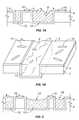
- FIG. 1Aillustrates a cross sectional view
- FIG. 1Billustrates a perspective view of a substrate after depositing the conductive material in the cavities.
- These figuresillustrate a dielectric or insulating layer 2 (e.g., silicon dioxide—SiO 2 ) having deposited thereon an adhesive or barrier layer 4 .
- the insulating layer 2is generally etched to form the cavities 12 therein before the barrier layer 4 is deposited thereon.
- the cavities 12 in the insulating layer 2are generally etched using a reactive ion etching (RIE) method.
- RIEreactive ion etching
- the barrier layer 4is generally deposited on the insulating layer 2 using any of the various sputtering methods, chemical vapor deposition (CVD), electro-deposition or electroless plating method.
- the barrier layer 4may be tantalum (Ta), titanium (Ti), tungsten (W), titanium-tungsten (TiW), titanium nitride (TiN), Nb, CuWP, CoWP, or other materials or combinations thereof that are commonly used in this field.
- a seed layer(not shown) is generally deposited thereon before the conductive material 6 such as copper is deposited on the substrate.
- the seed layeris the same material as the conductive material 6 .
- the conductive material 6can be deposited using CVD, sputtering, electroless plating, electro-deposition, or combinations thereof.
- the depths of the cavities 12 in the insulating layer 2can range from 0.02 to 200 um for interconnects and up to 1000 um or more for packages.
- the conductive material 6is generally deposited over the entire top surface of the substrate, i.e. in the cavities 12 as well as on the field regions 3 . It should be noted that the field regions 3 are defined as the top surface area of the substrate between the cavities 12 .
- the excess material deposited over the top plane of the field regions 3is known as the overburden.
- the thickness of the overburdenmay change over the various features of the substrate depending on their size. For example, in general, the overburden is thicker over the smaller cavities than the larger cavities.
- the substrateis typically transferred to an apparatus for polishing and removing the overburden from the top surface (i.e., field regions).
- the substrateis polished using a conventional chemical mechanical polishing (CMP) device and abrasive slurry.
- CMPchemical mechanical polishing
- some conductive material 6 grainsmay be removed from the cavities 12 , thereby resulting in substrates with various defects.
- certain grains of the conductive material 6 in the cavities 12may be corroded away because the abrasive slurry may attach itself to the conductive material 6 grains.
- some grains of the conductive material 6may be etched away from the cavities 12 , leaving defective portions 8 .
- defective portions 8may result from deep scratches during the CMP process.
- Defective portions 8may also result from the conductive material 6 deposition process itself.
- non-optimal deposition processesmay give rise to voids in conductive material 6 , and after polishing, such voids may result in the defective portions 8 .
- residual conductive material 10may not be completely removed and left on the barrier layer 4 , thereby resulting in additional defects.
- defectstypically reduce the quality of the conductive material 6 and device performance.
- FIG. 2illustrates a cross sectional view of a substrate having dishing effects.
- “dishing” or non-planar polishingmay result because of over polishing.
- a large recess 14may be formed in a large test pad portion, while a small recess 16 may be formed in a small bus line portion on the cavities 12 of the substrate.
- corrosion and other undesirable characteristicsmay result (i.e., dishing). Dishing may also result from wet etching processes. It is well known that existence of any kind of defects in the deposited conductive material results in poor device performance and low process yield.
- the present inventionrelates to methods for repairing defects on a semiconductor substrate. This is accomplished by selectively depositing the conductive material in defective portions in the cavities while removing residual portions from the field regions of the substrate. Another method according to the present invention includes forming a uniform conductive material overburden on the top surface of the substrate. The present invention also discloses a method for depositing a second conductive material on the first conductive material of the substrate.
- FIG. 1Aillustrates a cross sectional view of a conductive material disposed on a substrate having defects
- FIG. 1Billustrates a perspective view of FIG. 1A of a conductive material disposed on a substrate having defects
- FIG. 2illustrates a cross sectional view of a conductive material disposed on a substrate having “dishing” characteristics
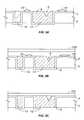
- FIGS. 3A-3Dillustrate cross sectional views of a method for repairing defects in accordance with the preferred embodiment of the present invention
- FIGS. 4A-4Cillustrate cross sectional views of a method for repairing defects in accordance with another preferred embodiment of the present invention.
- FIGS. 5A-5Billustrate cross sectional views of a method for depositing a second conductive material on a first conductive material in accordance with yet another preferred embodiment of the present invention.
- FIGS. 3-5wherein like structures and materials are designated by like reference numerals throughout the various figures. Further, specific details and processing parameters are provided herein and are intended to be explanatory rather than limiting.
- the inventors of the present inventiondisclose herein methods for repairing defects on a substrate.
- the present inventioncan be used with any substrate or workpiece such as a wafer, flat panel, magnetic film head, integrated circuit, device, chip, and packaging substrate, and it can be used with various conductive materials including, but not limited to copper, copper alloys, magnetic films, ferromagnetic films, lead tin solder alloys or lead free solder alloys.
- the defective substrateis preferably plated using an electro-deposition or electroless deposition process before removing the barrier layer from the top surface of the substrate.
- the barrier layeris used to conduct the electric current, and depending on the deposition time and current density, various portions of the substrate is plated accordingly.
- FIGS. 3A-3Dillustrate cross sectional views of a method for repairing defects in accordance with the first preferred embodiment of the present invention.
- defects in the cavities of the substrateare repaired by selectively plating over the defective regions, while simultaneously preventing deposition in the field regions of the substrate.
- the method shown in FIGS. 3A-3Dinclude the step of depositing a conductive material in the cavities of the substrate to repair the defects using an ECMD (electro-chemical mechanical deposition) device having a pad type material attached to an anode.
- ECMDelectro-chemical mechanical deposition
- Such apparatusis described in greater detail in the U.S. application Ser. No. 09/373,681, filed Aug. 13, 1999, entitled “Method and Apparatus for Depositing and Controlling the Texture of A Thin Film”, and now U.S. Pat. No. 6,409,904, the contents of which are expressly incorporated herein by reference.
- FIG. 3Aillustrates an insulating layer 2 having deposited thereon a barrier layer 4 , similar to that described above with reference to FIGS. 1A and 1B. Again, the top surface of the insulating layer 2 is patterned/etched with cavities 12 before the barrier layer 4 is deposited thereon.
- the insulating layer 2is preferably SiO 2 or polyimide, but it is understood that other materials that are commonly used as the insulating layer 2 may be used in accordance with the present invention.
- a porous pad type material 100 with or without fixed abrasive particles(not shown) is used to repair the defects 8 , 10 on the substrate. This is accomplished by selectively depositing the conductive material in the defective portion 8 while removing the residual material 10 from the field regions of the substrate.
- the pad type material 100is preferably attached to an anode (not shown) and may be rotated in a circular motion, vibrated, moved side to side or vertically when brought into contact with the top surface of the substrate. Likewise, the substrate may be rotated in a circular motion, vibrated, moved side to side or vertically when brought into contact with the pad type material 100 .
- the pad type material 100 and the substratemay rotate between 1 to 400 rpm, but preferably between 5 to 300 rpm, during the repairing mode.
- a suitable electrolyte containing the conductive material to be depositedis introduced between the pad and the substrate surface before a potential difference is applied between the anode and the barrier layer 4 causing the conductive material to deposit out of the electrolyte onto the substrate surface.
- An example of the suitable electrolyteis disclosed in the provisional U.S. application Ser. No. 06/182,100, filed Feb. 11, 2000, entitled “Modified Plating Solution for Plating and Planarization”, the contents of which are expressly incorporated herein by reference.
- an electrical current with a current density in the range of 0.05 to 20 mA/cm 2 , but preferably between 1 to 5 mA/cm 2is applied to the substrate using the ECMD device.
- the repairing processcan be performed for a period of 30 to 180 seconds when the pad 100 is in full contact with the substrate as shown in FIG. 3 C.
- the pad type material 100removes the residual material 10 residing on the field regions of the substrate while depositing the conductive material from the electrolyte into the defective portion 8 .
- the pad type material 100makes contact with the top surface of the substrate at a pressure that may range from 0.0 to 15 psi.
- the electrolyte containing the conductive materialmay emanate from the pad type material 100 and is applied to the substrate at a rate of 0.2 to 15 liters per minute, but preferably between 0.5 to 10 liters per minute on a conventional 8 inch diameter wafer. Using this method, a planar defect-free structure is obtained as shown in FIG. 3 D.
- the substrate surfacewith a uniform and planar layer of a conductive material.
- the method disclosed in FIGS. 4A-4Cis used to transform a defective substrate surface into a substrate having a planar conductive layer.
- FIG. 4Aa defective substrate similar to the one depicted in FIG. 3A is shown.
- a seed layer 5is deposited on the defective substrate surface.
- the seed layer 5may be 50-500 A in thickness. It may be a composite layer consisting of two or more layers. It is important to note that the seed layer 5 allows growth of a uniform conductive layer over it with good adhesion to the substrate surface. If the adhesion of the conductive layer to the barrier layer 4 is adequate, there may not be the need for the seed layer 5 .
- an electrical current with a current density in the range of 0.05 to 20 mA/cm2, but preferably between 1 to 10 mA/cm 2is applied to the substrate using the ECMD device.
- the pad 100does not make contact with the substrate, but does hydroplane over it.
- the repairing processcan be performed for a period of 20 to 300 seconds when the pad 100 is hydroplaning, as shown in FIG. 4 B. In this manner, the conductive material is deposited in the defective portion 8 and a uniform metal overburden 7 is built over the entire substrate surface as shown in FIG. 4C, while burying the residual materials 10 .
- the electrolyte solution containing the conductive material 7may emanate from the pad type material 100 and may be applied to the substrate at a rate of 0.2 to 6 liters per minute.
- the pressuremay be 0.1 to 2 psi.
- Low pressure between the substrate and the pad 100 and high electrolyte flowallow the pad 100 to hydroplane over the substrate surface.
- Both the substrate and the pad 100may be rotated during deposition at 5 to 300 rpm.
- the present techniquemay be used to planarize a defect free but non-uniform or dished conductive surface on a substrate as shown in FIGS. 5A and 5B.
- the non-uniform layer 110 on the surface of the substrate of FIG. 5Ais coated with a planar layer 120 resulting in the structure of FIG. 5 B.
- the conductive materials 110 , 120may be the same materials. In the alternative, the conductive materials 110 , 120 may be different materials.
- the second conductive material 120may be Cu—Sn, Cu—In, WCoP or CoP, or other suitable copper alloys, cobalt alloys, silver alloys, etc.
- the first conductive material 110may be Cu.
- the second conductive material 120should be a material that will enhance corrosion resistance and electromigration, while providing excellent adhesion to the first conductive material 110 and to other subsequently deposited materials that may be formed thereon.
- the second conductive material 120may have an electrical resistivity that is very similar to the first conductive material 110 , preferably within 90-200% of that of the first conductive material 110 .
- first and second conductive materials 110 , 120are the same materials, a distinct boundary between them may not exist.
- first and second conductive materials 110 , 120are different, a distinct boundary between them may exist before any subsequent thermal process is performed.
- the distinct boundary layercan be used so that intermixing between the first and second conductive materials 110 , 120 is discouraged.
- a thin adhesive or barrier layere.g., alpha Tantalum, chrome layer, CoP, WCoP
- more than two conductive materialscan be formed in the cavities of the substrate using the process disclosed herein.
- the entire substrate as shown in FIG. 5Bmay be polished by CMP to produce high yield devices.
- the overburdencan be removed by wet etch, electropolishing, or electroplating.
- conductive materialsuch as aluminum, iron, nickel, chromium, indium, lead, tin, lead-tin alloys, nonleaded solderable alloys, silver, zinc, cadmium, titanium, tungsten molybdenum, ruthenium, gold, paladium, cobalt, rhondium, platinum, their respective alloys and various combinations of above materials with oxygen, nitrogen, hydrogen and phosphorous may be used in the present invention.
- the repairing steps described abovemay be performed in an electroless deposition bath.
- Various processing conditionssuch as plating bath temperature, pressure, pad material, pad design, solution flow rate, and the like can be varied to repair the defects in the substrate material.
- the conductive material or seed layer used for repairing the defectdoes not need to be homogeneous with the defective conductive material base.
- the seed layer 5need not be copper, but may be silver, or a copper or silver based alloy such as copper indium alloy, copper silver alloy or even silver indium alloy.
- the defectsare repaired using the methods described earlier, using the seed layer and barrier to carry the current.
- the non-homogeneous seed layeris now part of the overburden 7 .
Landscapes
- Engineering & Computer Science (AREA)
- Physics & Mathematics (AREA)
- Condensed Matter Physics & Semiconductors (AREA)
- General Physics & Mathematics (AREA)
- Manufacturing & Machinery (AREA)
- Computer Hardware Design (AREA)
- Microelectronics & Electronic Packaging (AREA)
- Power Engineering (AREA)
- Internal Circuitry In Semiconductor Integrated Circuit Devices (AREA)
Abstract
Description
Claims (25)
Priority Applications (4)
| Application Number | Priority Date | Filing Date | Title |
|---|---|---|---|
| US09/534,704US6582579B1 (en) | 2000-03-24 | 2000-03-24 | Methods for repairing defects on a semiconductor substrate |
| AU2001245980AAU2001245980A1 (en) | 2000-03-24 | 2001-03-22 | Methods for repairing defects on a semiconductor substrate |
| PCT/US2001/009500WO2001078135A2 (en) | 2000-03-24 | 2001-03-22 | Methods for repairing defects on a semiconductor substrate |
| US10/425,783US20040035709A1 (en) | 2000-03-24 | 2003-04-29 | Methods for repairing defects on a semiconductor substrate |
Applications Claiming Priority (1)
| Application Number | Priority Date | Filing Date | Title |
|---|---|---|---|
| US09/534,704US6582579B1 (en) | 2000-03-24 | 2000-03-24 | Methods for repairing defects on a semiconductor substrate |
Related Child Applications (1)
| Application Number | Title | Priority Date | Filing Date |
|---|---|---|---|
| US10/425,783ContinuationUS20040035709A1 (en) | 2000-03-24 | 2003-04-29 | Methods for repairing defects on a semiconductor substrate |
Publications (1)
| Publication Number | Publication Date |
|---|---|
| US6582579B1true US6582579B1 (en) | 2003-06-24 |
Family
ID=24131177
Family Applications (2)
| Application Number | Title | Priority Date | Filing Date |
|---|---|---|---|
| US09/534,704Expired - LifetimeUS6582579B1 (en) | 2000-03-24 | 2000-03-24 | Methods for repairing defects on a semiconductor substrate |
| US10/425,783AbandonedUS20040035709A1 (en) | 2000-03-24 | 2003-04-29 | Methods for repairing defects on a semiconductor substrate |
Family Applications After (1)
| Application Number | Title | Priority Date | Filing Date |
|---|---|---|---|
| US10/425,783AbandonedUS20040035709A1 (en) | 2000-03-24 | 2003-04-29 | Methods for repairing defects on a semiconductor substrate |
Country Status (3)
| Country | Link |
|---|---|
| US (2) | US6582579B1 (en) |
| AU (1) | AU2001245980A1 (en) |
| WO (1) | WO2001078135A2 (en) |
Cited By (16)
| Publication number | Priority date | Publication date | Assignee | Title |
|---|---|---|---|---|
| US20030040188A1 (en)* | 2001-08-24 | 2003-02-27 | Applied Materials, Inc. | Method for dishing reduction and feature passivation in polishing processes |
| US20030080431A1 (en)* | 2001-10-27 | 2003-05-01 | Cyprian Uzoh | Method and structure for thru-mask contact electrodeposition |
| US20030139053A1 (en)* | 2001-12-21 | 2003-07-24 | Uzoh Cyprian E. | Method and system to provide electroplanarization of a workpiece with a conducting material layer |
| US20030178320A1 (en)* | 2001-03-14 | 2003-09-25 | Applied Materials, Inc. | Method and composition for polishing a substrate |
| US20040053499A1 (en)* | 2001-03-14 | 2004-03-18 | Applied Materials, Inc. | Method and composition for polishing a substrate |
| US20040253809A1 (en)* | 2001-08-18 | 2004-12-16 | Yao Xiang Yu | Forming a semiconductor structure using a combination of planarizing methods and electropolishing |
| US20050056537A1 (en)* | 2001-03-14 | 2005-03-17 | Liang-Yuh Chen | Planarization of substrates using electrochemical mechanical polishing |
| US20050145507A1 (en)* | 2001-12-21 | 2005-07-07 | Applied Materials, Inc. | Electrolyte with good planarization capability, high removal rate and smooth surface finish for electrochemically controlled copper CMP |
| US20060006074A1 (en)* | 2001-03-14 | 2006-01-12 | Liu Feng Q | Method and composition for polishing a substrate |
| US20060104855A1 (en)* | 2004-11-15 | 2006-05-18 | Metallic Resources, Inc. | Lead-free solder alloy |
| US20060169597A1 (en)* | 2001-03-14 | 2006-08-03 | Applied Materials, Inc. | Method and composition for polishing a substrate |
| US20060249394A1 (en)* | 2005-05-05 | 2006-11-09 | Applied Materials, Inc. | Process and composition for electrochemical mechanical polishing |
| US7390429B2 (en) | 2003-06-06 | 2008-06-24 | Applied Materials, Inc. | Method and composition for electrochemical mechanical polishing processing |
| WO2010042263A1 (en)* | 2008-10-08 | 2010-04-15 | International Business Machines Corporation | Surface repair structure and process for interconnect applications |
| US9837341B1 (en)* | 2016-09-15 | 2017-12-05 | Intel Corporation | Tin-zinc microbump structures |
| US20190393409A1 (en)* | 2018-06-25 | 2019-12-26 | International Business Machines Corporation | Back end of line metallization structures |
Families Citing this family (9)
| Publication number | Priority date | Publication date | Assignee | Title |
|---|---|---|---|---|
| WO2002023613A2 (en)* | 2000-09-15 | 2002-03-21 | Rodel Holdings, Inc. | Metal cmp process with reduced dishing |
| US6943112B2 (en)* | 2002-07-22 | 2005-09-13 | Asm Nutool, Inc. | Defect-free thin and planar film processing |
| US6864181B2 (en)* | 2003-03-27 | 2005-03-08 | Lam Research Corporation | Method and apparatus to form a planarized Cu interconnect layer using electroless membrane deposition |
| US7247558B2 (en) | 2004-12-03 | 2007-07-24 | Novellus Systems, Inc. | Method and system for electroprocessing conductive layers |
| US7485561B2 (en) | 2006-03-29 | 2009-02-03 | Asm Nutool, Inc. | Filling deep features with conductors in semiconductor manufacturing |
| US7625814B2 (en) | 2006-03-29 | 2009-12-01 | Asm Nutool, Inc. | Filling deep features with conductors in semiconductor manufacturing |
| US7884016B2 (en) | 2009-02-12 | 2011-02-08 | Asm International, N.V. | Liner materials and related processes for 3-D integration |
| WO2015171180A1 (en)* | 2014-05-05 | 2015-11-12 | Apple Inc. | Methods for forming defect-free anodized parts |
| US20180096858A1 (en)* | 2016-09-30 | 2018-04-05 | International Business Machines Corporation | Metalization repair in semiconductor wafers |
Citations (25)
| Publication number | Priority date | Publication date | Assignee | Title |
|---|---|---|---|---|
| US3959089A (en) | 1972-07-31 | 1976-05-25 | Watts John Dawson | Surface finishing and plating method |
| US4610772A (en) | 1985-07-22 | 1986-09-09 | The Carolinch Company | Electrolytic plating apparatus |
| US5024735A (en) | 1989-02-15 | 1991-06-18 | Kadija Igor V | Method and apparatus for manufacturing interconnects with fine lines and spacing |
| US5142828A (en) | 1990-06-25 | 1992-09-01 | Microelectronics And Computer Technology Corporation | Correcting a defective metallization layer on an electronic component by polishing |
| US5171412A (en) | 1991-08-23 | 1992-12-15 | Applied Materials, Inc. | Material deposition method for integrated circuit manufacturing |
| US5429733A (en) | 1992-05-21 | 1995-07-04 | Electroplating Engineers Of Japan, Ltd. | Plating device for wafer |
| US5558568A (en) | 1994-10-11 | 1996-09-24 | Ontrak Systems, Inc. | Wafer polishing machine with fluid bearings |
| US5692947A (en) | 1994-08-09 | 1997-12-02 | Ontrak Systems, Inc. | Linear polisher and method for semiconductor wafer planarization |
| US5755859A (en) | 1995-08-24 | 1998-05-26 | International Business Machines Corporation | Cobalt-tin alloys and their applications for devices, chip interconnections and packaging |
| US5807165A (en) | 1997-03-26 | 1998-09-15 | International Business Machines Corporation | Method of electrochemical mechanical planarization |
| US5833820A (en) | 1997-06-19 | 1998-11-10 | Advanced Micro Devices, Inc. | Electroplating apparatus |
| EP0878834A2 (en) | 1997-05-12 | 1998-11-18 | Motorola, Inc. | A method for preventing electroplanting of copper on an exposed surface at the edge exclusion of a semiconductor wafer |
| US5863412A (en) | 1995-10-17 | 1999-01-26 | Canon Kabushiki Kaisha | Etching method and process for producing a semiconductor element using said etching method |
| US5882498A (en) | 1997-10-16 | 1999-03-16 | Advanced Micro Devices, Inc. | Method for reducing oxidation of electroplating chamber contacts and improving uniform electroplating of a substrate |
| US5911619A (en) | 1997-03-26 | 1999-06-15 | International Business Machines Corporation | Apparatus for electrochemical mechanical planarization |
| EP0928024A2 (en) | 1998-01-05 | 1999-07-07 | Texas Instruments Incorporated | Improvements in or relating to interconnect conducting paths |
| US5930669A (en) | 1997-04-03 | 1999-07-27 | International Business Machines Corporation | Continuous highly conductive metal wiring structures and method for fabricating the same |
| US5928492A (en) | 1997-06-05 | 1999-07-27 | Lucid Treatment Systems, Inc. | Method and apparatus for recovery of water and slurry abrasives used for chemical and mechanical planarization |
| US5933753A (en) | 1996-12-16 | 1999-08-03 | International Business Machines Corporation | Open-bottomed via liner structure and method for fabricating same |
| US6004880A (en) | 1998-02-20 | 1999-12-21 | Lsi Logic Corporation | Method of single step damascene process for deposition and global planarization |
| US6168704B1 (en)* | 1999-02-04 | 2001-01-02 | Advanced Micro Device, Inc. | Site-selective electrochemical deposition of copper |
| US6171467B1 (en)* | 1997-11-25 | 2001-01-09 | The John Hopkins University | Electrochemical-control of abrasive polishing and machining rates |
| US6176992B1 (en)* | 1998-11-03 | 2001-01-23 | Nutool, Inc. | Method and apparatus for electro-chemical mechanical deposition |
| US6218290B1 (en)* | 1998-11-25 | 2001-04-17 | Advanced Micro Devices, Inc. | Copper dendrite prevention by chemical removal of dielectric |
| US6290833B1 (en)* | 1998-03-20 | 2001-09-18 | Semitool, Inc. | Method for electrolytically depositing copper on a semiconductor workpiece |
Family Cites Families (6)
| Publication number | Priority date | Publication date | Assignee | Title |
|---|---|---|---|---|
| US5855804A (en)* | 1996-12-06 | 1999-01-05 | Micron Technology, Inc. | Method and apparatus for stopping mechanical and chemical-mechanical planarization of substrates at desired endpoints |
| US5972192A (en)* | 1997-07-23 | 1999-10-26 | Advanced Micro Devices, Inc. | Pulse electroplating copper or copper alloys |
| US6107186A (en)* | 1999-01-27 | 2000-08-22 | Advanced Micro Devices, Inc. | High planarity high-density in-laid metallization patterns by damascene-CMP processing |
| US6103624A (en)* | 1999-04-15 | 2000-08-15 | Advanced Micro Devices, Inc. | Method of improving Cu damascene interconnect reliability by laser anneal before barrier polish |
| US6465376B2 (en)* | 1999-08-18 | 2002-10-15 | International Business Machines Corporation | Method and structure for improving electromigration of chip interconnects |
| US6612915B1 (en)* | 1999-12-27 | 2003-09-02 | Nutool Inc. | Work piece carrier head for plating and polishing |
- 2000
- 2000-03-24USUS09/534,704patent/US6582579B1/ennot_activeExpired - Lifetime
- 2001
- 2001-03-22WOPCT/US2001/009500patent/WO2001078135A2/enactiveApplication Filing
- 2001-03-22AUAU2001245980Apatent/AU2001245980A1/ennot_activeAbandoned
- 2003
- 2003-04-29USUS10/425,783patent/US20040035709A1/ennot_activeAbandoned
Patent Citations (25)
| Publication number | Priority date | Publication date | Assignee | Title |
|---|---|---|---|---|
| US3959089A (en) | 1972-07-31 | 1976-05-25 | Watts John Dawson | Surface finishing and plating method |
| US4610772A (en) | 1985-07-22 | 1986-09-09 | The Carolinch Company | Electrolytic plating apparatus |
| US5024735A (en) | 1989-02-15 | 1991-06-18 | Kadija Igor V | Method and apparatus for manufacturing interconnects with fine lines and spacing |
| US5142828A (en) | 1990-06-25 | 1992-09-01 | Microelectronics And Computer Technology Corporation | Correcting a defective metallization layer on an electronic component by polishing |
| US5171412A (en) | 1991-08-23 | 1992-12-15 | Applied Materials, Inc. | Material deposition method for integrated circuit manufacturing |
| US5429733A (en) | 1992-05-21 | 1995-07-04 | Electroplating Engineers Of Japan, Ltd. | Plating device for wafer |
| US5692947A (en) | 1994-08-09 | 1997-12-02 | Ontrak Systems, Inc. | Linear polisher and method for semiconductor wafer planarization |
| US5558568A (en) | 1994-10-11 | 1996-09-24 | Ontrak Systems, Inc. | Wafer polishing machine with fluid bearings |
| US5755859A (en) | 1995-08-24 | 1998-05-26 | International Business Machines Corporation | Cobalt-tin alloys and their applications for devices, chip interconnections and packaging |
| US5863412A (en) | 1995-10-17 | 1999-01-26 | Canon Kabushiki Kaisha | Etching method and process for producing a semiconductor element using said etching method |
| US5933753A (en) | 1996-12-16 | 1999-08-03 | International Business Machines Corporation | Open-bottomed via liner structure and method for fabricating same |
| US5807165A (en) | 1997-03-26 | 1998-09-15 | International Business Machines Corporation | Method of electrochemical mechanical planarization |
| US5911619A (en) | 1997-03-26 | 1999-06-15 | International Business Machines Corporation | Apparatus for electrochemical mechanical planarization |
| US5930669A (en) | 1997-04-03 | 1999-07-27 | International Business Machines Corporation | Continuous highly conductive metal wiring structures and method for fabricating the same |
| EP0878834A2 (en) | 1997-05-12 | 1998-11-18 | Motorola, Inc. | A method for preventing electroplanting of copper on an exposed surface at the edge exclusion of a semiconductor wafer |
| US5928492A (en) | 1997-06-05 | 1999-07-27 | Lucid Treatment Systems, Inc. | Method and apparatus for recovery of water and slurry abrasives used for chemical and mechanical planarization |
| US5833820A (en) | 1997-06-19 | 1998-11-10 | Advanced Micro Devices, Inc. | Electroplating apparatus |
| US5882498A (en) | 1997-10-16 | 1999-03-16 | Advanced Micro Devices, Inc. | Method for reducing oxidation of electroplating chamber contacts and improving uniform electroplating of a substrate |
| US6171467B1 (en)* | 1997-11-25 | 2001-01-09 | The John Hopkins University | Electrochemical-control of abrasive polishing and machining rates |
| EP0928024A2 (en) | 1998-01-05 | 1999-07-07 | Texas Instruments Incorporated | Improvements in or relating to interconnect conducting paths |
| US6004880A (en) | 1998-02-20 | 1999-12-21 | Lsi Logic Corporation | Method of single step damascene process for deposition and global planarization |
| US6290833B1 (en)* | 1998-03-20 | 2001-09-18 | Semitool, Inc. | Method for electrolytically depositing copper on a semiconductor workpiece |
| US6176992B1 (en)* | 1998-11-03 | 2001-01-23 | Nutool, Inc. | Method and apparatus for electro-chemical mechanical deposition |
| US6218290B1 (en)* | 1998-11-25 | 2001-04-17 | Advanced Micro Devices, Inc. | Copper dendrite prevention by chemical removal of dielectric |
| US6168704B1 (en)* | 1999-02-04 | 2001-01-02 | Advanced Micro Device, Inc. | Site-selective electrochemical deposition of copper |
Non-Patent Citations (8)
| Title |
|---|
| "Spot Plating Tool for Thin Film Circuit Repair"; IBM Technical Disclosure Bulletin, IBM Corp., New York, U.S., vol. 32, No. 12, May 1, 1990, pp. 439-440. |
| Alan C. West, et al., "Pulse Reverse Copper Electrodeposition in High Aspect Ration Trenches and Vias", Sep. 1998, pp. 3070-3073. |
| C. Madore, et al., "Blocking Inhibitors in Catholic Leveling", I. "Theoretical Analysis", Dec. 1996, pp. 3927-3942. |
| J.M. Steigerwald, et al., "Pattern Geometry Effects in the Chemical-Mechanical Polishing of Inlaid Copper Structures", Oct. 1994, pp. 2842-2848. |
| M. Rubenstein, "Tamponglavanisieren in der Praxis Teil 1" Galvanotechnik, vol. 79, No. 10, 1988 pp. 3263-3270 (no month). |
| Moosburger, G.: "Selbstheilende ICS"; Elektronik, Franzis Verlag GMBH, Munchen, DE, vol. 39, No. 19, Sep. 14, 1990, p. 23. |
| Robert C. Contolini, et al., "Electrochemical Planarization for Multilevel Metallization", Sep. 1994, pp. 2503-2510. |
| Steigerwald J.M. et al; Electrochemical Potential Measurements During the Chemical-Mechanical Polishing of Copper Thin Films Journal of the Electrochemical Society, Electrochemical Society, Manchester, NH, U.S., vol. 142, No. 7, Jul. 1995, pp. 2379-2385. |
Cited By (33)
| Publication number | Priority date | Publication date | Assignee | Title |
|---|---|---|---|---|
| US7128825B2 (en) | 2001-03-14 | 2006-10-31 | Applied Materials, Inc. | Method and composition for polishing a substrate |
| US7323416B2 (en) | 2001-03-14 | 2008-01-29 | Applied Materials, Inc. | Method and composition for polishing a substrate |
| US20030178320A1 (en)* | 2001-03-14 | 2003-09-25 | Applied Materials, Inc. | Method and composition for polishing a substrate |
| US20040053499A1 (en)* | 2001-03-14 | 2004-03-18 | Applied Materials, Inc. | Method and composition for polishing a substrate |
| US7160432B2 (en)* | 2001-03-14 | 2007-01-09 | Applied Materials, Inc. | Method and composition for polishing a substrate |
| US20060006074A1 (en)* | 2001-03-14 | 2006-01-12 | Liu Feng Q | Method and composition for polishing a substrate |
| US20050056537A1 (en)* | 2001-03-14 | 2005-03-17 | Liang-Yuh Chen | Planarization of substrates using electrochemical mechanical polishing |
| US20060169597A1 (en)* | 2001-03-14 | 2006-08-03 | Applied Materials, Inc. | Method and composition for polishing a substrate |
| US20040253809A1 (en)* | 2001-08-18 | 2004-12-16 | Yao Xiang Yu | Forming a semiconductor structure using a combination of planarizing methods and electropolishing |
| US20030040188A1 (en)* | 2001-08-24 | 2003-02-27 | Applied Materials, Inc. | Method for dishing reduction and feature passivation in polishing processes |
| US6884724B2 (en) | 2001-08-24 | 2005-04-26 | Applied Materials, Inc. | Method for dishing reduction and feature passivation in polishing processes |
| US20050202677A1 (en)* | 2001-08-24 | 2005-09-15 | Wei-Yung Hsu | Method for dishing reduction and feature passivation in polishing processes |
| US20030080431A1 (en)* | 2001-10-27 | 2003-05-01 | Cyprian Uzoh | Method and structure for thru-mask contact electrodeposition |
| US20050042873A1 (en)* | 2001-12-21 | 2005-02-24 | Uzoh Cyprian E. | Method and system to provide electroplanarization of a workpiece with a conducting material layer |
| US7229535B2 (en) | 2001-12-21 | 2007-06-12 | Applied Materials, Inc. | Hydrogen bubble reduction on the cathode using double-cell designs |
| US20050145507A1 (en)* | 2001-12-21 | 2005-07-07 | Applied Materials, Inc. | Electrolyte with good planarization capability, high removal rate and smooth surface finish for electrochemically controlled copper CMP |
| US7384534B2 (en) | 2001-12-21 | 2008-06-10 | Applied Materials, Inc. | Electrolyte with good planarization capability, high removal rate and smooth surface finish for electrochemically controlled copper CMP |
| US20030139053A1 (en)* | 2001-12-21 | 2003-07-24 | Uzoh Cyprian E. | Method and system to provide electroplanarization of a workpiece with a conducting material layer |
| US6780772B2 (en)* | 2001-12-21 | 2004-08-24 | Nutool, Inc. | Method and system to provide electroplanarization of a workpiece with a conducting material layer |
| US7390429B2 (en) | 2003-06-06 | 2008-06-24 | Applied Materials, Inc. | Method and composition for electrochemical mechanical polishing processing |
| US20040248412A1 (en)* | 2003-06-06 | 2004-12-09 | Liu Feng Q. | Method and composition for fine copper slurry for low dishing in ECMP |
| US9587293B2 (en) | 2004-11-15 | 2017-03-07 | Stanley R. Rothschild | Lead-free solder alloy |
| US20060104855A1 (en)* | 2004-11-15 | 2006-05-18 | Metallic Resources, Inc. | Lead-free solder alloy |
| US20090008434A1 (en)* | 2004-11-15 | 2009-01-08 | Metallic Resources, Inc. | Lead-Free Solder Alloy |
| US20060249394A1 (en)* | 2005-05-05 | 2006-11-09 | Applied Materials, Inc. | Process and composition for electrochemical mechanical polishing |
| WO2010042263A1 (en)* | 2008-10-08 | 2010-04-15 | International Business Machines Corporation | Surface repair structure and process for interconnect applications |
| US8802563B2 (en) | 2008-10-08 | 2014-08-12 | International Business Machines Corporation | Surface repair structure and process for interconnect applications |
| US9837341B1 (en)* | 2016-09-15 | 2017-12-05 | Intel Corporation | Tin-zinc microbump structures |
| KR20190043533A (en)* | 2016-09-15 | 2019-04-26 | 인텔 코포레이션 | Tin-zinc microbump structures and method of making same |
| US10373900B2 (en) | 2016-09-15 | 2019-08-06 | Intel Corporation | Tin-zinc microbump structures and method of making same |
| US20190393409A1 (en)* | 2018-06-25 | 2019-12-26 | International Business Machines Corporation | Back end of line metallization structures |
| US10686126B2 (en) | 2018-06-25 | 2020-06-16 | International Business Machiness Corporation | Back end of line metallization structures |
| US10741748B2 (en)* | 2018-06-25 | 2020-08-11 | International Business Machines Corporation | Back end of line metallization structures |
Also Published As
| Publication number | Publication date |
|---|---|
| AU2001245980A1 (en) | 2001-10-23 |
| WO2001078135A2 (en) | 2001-10-18 |
| WO2001078135A3 (en) | 2002-02-21 |
| US20040035709A1 (en) | 2004-02-26 |
Similar Documents
| Publication | Publication Date | Title |
|---|---|---|
| US6582579B1 (en) | Methods for repairing defects on a semiconductor substrate | |
| US10804151B2 (en) | Systems and methods for producing flat surfaces in interconnect structures | |
| US7172497B2 (en) | Fabrication of semiconductor interconnect structures | |
| JP3075533B2 (en) | Method for selectively filling recess with conductive metal and semiconductor structure having the recess | |
| CN101577247B (en) | Integrating metal with ultra low-k dielectrics | |
| CN100492607C (en) | Microelectronic device including conductive bumps and manufacturing method thereof | |
| US20020153256A1 (en) | Method and apparatus for depositing and controlling the texture of a thin film | |
| US20040219779A1 (en) | Method and structure to improve reliability of copper interconnects | |
| US6974769B2 (en) | Conductive structure fabrication process using novel layered structure and conductive structure fabricated thereby for use in multi-level metallization | |
| US20030201538A1 (en) | Method of forming metal interconnection using plating and semiconductor device manufactured by the method | |
| US6319834B1 (en) | Method and apparatus for improved planarity metallization by electroplating and CMP | |
| JP2004533123A (en) | Barrier enhancement process for copper connections | |
| JPH11274208A (en) | Method for obtaining copper stud by c4 plating | |
| TW508687B (en) | Local area alloying for preventing dishing of copper during chemical-mechanical polishing(CMP) | |
| JP4297292B2 (en) | Semiconductor device wiring formation method and semiconductor device | |
| KR100859899B1 (en) | Electrochemical Method of Polishing Copper Film on Semiconductor Substrate | |
| US7204743B2 (en) | Integrated circuit interconnect fabrication systems | |
| US6350678B1 (en) | Chemical-mechanical polishing of semiconductors | |
| US7247558B2 (en) | Method and system for electroprocessing conductive layers | |
| US7202161B2 (en) | Substrate processing method and apparatus | |
| US6797144B2 (en) | Method for reducing surface defects in an electrodeposition process | |
| US20030168345A1 (en) | In-situ monitor seed for copper plating | |
| US6777807B1 (en) | Interconnect integration | |
| JP2005044913A (en) | Semiconductor device and manufacturing method thereof |
Legal Events
| Date | Code | Title | Description |
|---|---|---|---|
| AS | Assignment | Owner name:NUTOOL, INC., CALIFORNIA Free format text:ASSIGNMENT OF ASSIGNORS INTEREST;ASSIGNOR:UZOH, CYPRIAN E.;REEL/FRAME:010669/0542 Effective date:20000322 | |
| STCF | Information on status: patent grant | Free format text:PATENTED CASE | |
| FEPP | Fee payment procedure | Free format text:PAYOR NUMBER ASSIGNED (ORIGINAL EVENT CODE: ASPN); ENTITY STATUS OF PATENT OWNER: LARGE ENTITY | |
| AS | Assignment | Owner name:ASM NUTOOL, INC., CALIFORNIA Free format text:CHANGE OF NAME;ASSIGNOR:NUTOOL, INC.;REEL/FRAME:015748/0100 Effective date:20040729 | |
| REMI | Maintenance fee reminder mailed | ||
| FPAY | Fee payment | Year of fee payment:4 | |
| SULP | Surcharge for late payment | ||
| AS | Assignment | Owner name:NOVELLUS SYSTEMS, INC.,CALIFORNIA Free format text:ASSIGNMENT OF ASSIGNORS INTEREST;ASSIGNOR:ASM NUTOOL, INC.;REEL/FRAME:019000/0080 Effective date:20061204 Owner name:NOVELLUS SYSTEMS, INC., CALIFORNIA Free format text:ASSIGNMENT OF ASSIGNORS INTEREST;ASSIGNOR:ASM NUTOOL, INC.;REEL/FRAME:019000/0080 Effective date:20061204 | |
| FEPP | Fee payment procedure | Free format text:PAYOR NUMBER ASSIGNED (ORIGINAL EVENT CODE: ASPN); ENTITY STATUS OF PATENT OWNER: LARGE ENTITY Free format text:PAYER NUMBER DE-ASSIGNED (ORIGINAL EVENT CODE: RMPN); ENTITY STATUS OF PATENT OWNER: LARGE ENTITY | |
| FEPP | Fee payment procedure | Free format text:PAYOR NUMBER ASSIGNED (ORIGINAL EVENT CODE: ASPN); ENTITY STATUS OF PATENT OWNER: LARGE ENTITY Free format text:PAYER NUMBER DE-ASSIGNED (ORIGINAL EVENT CODE: RMPN); ENTITY STATUS OF PATENT OWNER: LARGE ENTITY | |
| FPAY | Fee payment | Year of fee payment:8 | |
| FPAY | Fee payment | Year of fee payment:12 |