US6582403B1 - Universal catheter anchoring system - Google Patents
Universal catheter anchoring systemDownload PDFInfo
- Publication number
- US6582403B1 US6582403B1US09/513,054US51305400AUS6582403B1US 6582403 B1US6582403 B1US 6582403B1US 51305400 AUS51305400 AUS 51305400AUS 6582403 B1US6582403 B1US 6582403B1
- Authority
- US
- United States
- Prior art keywords
- base
- cover
- post
- anchoring system
- retainer
- Prior art date
- Legal status (The legal status is an assumption and is not a legal conclusion. Google has not performed a legal analysis and makes no representation as to the accuracy of the status listed.)
- Expired - Lifetime
Links
Images


Classifications
- A—HUMAN NECESSITIES
- A61—MEDICAL OR VETERINARY SCIENCE; HYGIENE
- A61M—DEVICES FOR INTRODUCING MEDIA INTO, OR ONTO, THE BODY; DEVICES FOR TRANSDUCING BODY MEDIA OR FOR TAKING MEDIA FROM THE BODY; DEVICES FOR PRODUCING OR ENDING SLEEP OR STUPOR
- A61M25/00—Catheters; Hollow probes
- A61M25/01—Introducing, guiding, advancing, emplacing or holding catheters
- A61M25/02—Holding devices, e.g. on the body
- A61M2025/024—Holding devices, e.g. on the body having a clip or clamp system
- A—HUMAN NECESSITIES
- A61—MEDICAL OR VETERINARY SCIENCE; HYGIENE
- A61M—DEVICES FOR INTRODUCING MEDIA INTO, OR ONTO, THE BODY; DEVICES FOR TRANSDUCING BODY MEDIA OR FOR TAKING MEDIA FROM THE BODY; DEVICES FOR PRODUCING OR ENDING SLEEP OR STUPOR
- A61M25/00—Catheters; Hollow probes
- A61M25/01—Introducing, guiding, advancing, emplacing or holding catheters
- A61M25/02—Holding devices, e.g. on the body
- A61M2025/0246—Holding devices, e.g. on the body fixed on the skin having a cover for covering the holding means
- A—HUMAN NECESSITIES
- A61—MEDICAL OR VETERINARY SCIENCE; HYGIENE
- A61M—DEVICES FOR INTRODUCING MEDIA INTO, OR ONTO, THE BODY; DEVICES FOR TRANSDUCING BODY MEDIA OR FOR TAKING MEDIA FROM THE BODY; DEVICES FOR PRODUCING OR ENDING SLEEP OR STUPOR
- A61M25/00—Catheters; Hollow probes
- A61M25/01—Introducing, guiding, advancing, emplacing or holding catheters
- A61M25/02—Holding devices, e.g. on the body
- A61M2025/0266—Holding devices, e.g. on the body using pads, patches, tapes or the like
Definitions
- the present inventionrelates in general to a universal anchoring system for securing a medical article to a patient and, in particular, to a universal anchoring system for securing a catheter to a patient to inhibit movement or migration of the catheter relative to the patient.
- CVCcentral venous catheter
- the catheterIn most cases, the catheter remains in place for many days.
- a healthcare workerIn order to secure the catheter in position at the insertion site, a healthcare worker often secures the catheter to the patient using tape. That is, the healthcare worker commonly places long pieces of tape across the portion of the catheter near the insertion site in a crisscross pattern to secure the catheter to the patient's skin. This securement inhibits disconnection between the catheter and the insertion site, and also prevents the catheter from snagging on the bed rail or other objects.
- Tapehowever, often collects dirt and other contaminates. Normal protocol therefore requires periodic (e.g., daily) tape changes to inhibit bacteria and germ growth at the securement site. These frequent tape changes often excoriate the patient's skin. Additionally, valuable time is spent by healthcare workers applying and reapplying the tape. Because many healthcare workers find the taping procedure cumbersome and difficult to accomplish when wearing gloves, they often remove their gloves when taping. Not only does this increase the amount of time spent on the taping procedure, but it also subjects the healthcare worker to an increased risk of infection. Moreover, even if healthcare workers remain gloved, contact between the adhesive surface of the tape and the latex gloves can cause micro-holes in the gloves, subjecting the healthcare worker to possible infection.
- a variety of catheter securement deviceshave been developed to obviate the need for frequent application of tape to secure a catheter to a patient.
- One such securement deviceprovides a flexible clamp with winged extensions that are sutured to the patient's skin.
- the winged extensionsare integrally formed with catheter.
- the flexible clampis covered by a rigid fitting, which receives the catheter/clamp combination in a friction-fit manner.
- the rigid fitting and flexible clampare formed with lateral, aligned holes, which allow the combination to be sutured to the patient's skin.
- suture materialtends to exhibit poor gripping on medical tubes and can cut through the winged extension of the flexible clamp if a rigid clamp is not used.
- a rigid fittingcomplicates the securement procedure by adding yet another component that can be dropped on the floor and become unsterile.
- the sutured securement of the flexible clamp and/or the rigid fitting assemblydoes not permit easy release of the catheter from the patient for dressing changes and insertion site cleaning.
- a removal instrumente.g., sterile scissors also is generally required for suture removal.
- catheter securement devicesRather than suturing lateral, aligned holes to a patient's skin, other catheter securement devices provide an adhesive layer or resilient band interposed between the flexible clamp and the patient's skin. See, for example, U.S. Pat. Nos. 5,342,317; 5,192,274; 5,084,026; 4,449,975; and 4,250,880. Many of these securement devices, however, suffer from one or more of the following disadvantages: are time consuming and inconvenient to secure; have multiple parts, which can be dropped and become none sterile; and require removal instruments (e.g., hemostat or scissors) to disengage the catheter from the securement device.
- removal instrumentse.g., hemostat or scissors
- the present inventionprovides a simply-structured anchoring system that secures a catheter in a fixed position, but easily releases the catheter for dressing changes or other servicing.
- the present inventionalso recognizes that prior art catheter anchoring systems have been dedicated to a particular catheter, catheter fitting or catheter manufacturer.
- the present anchoring systemalso can cooperate with the suture or mounting holes of many different catheter and catheter fitting designs.
- the present anchoring systemcan be adjusted so as to be used with a variety of catheters and/or catheter fittings which have varying distances between the suture or mounting holes of the catheter and/or fitting.
- the anchoring systemcomprises an anchor pad having an upper surface and a lower surface. At least a portion of the lower surface has an adhesive surface to attach the anchor pad to the body of the patient.
- a retaineris mounted on the upper surface of the anchor pad and is capable of receiving a portion of the medical article.
- the retainerincludes a base, a cover, and a post.
- the baseis disposed on the upper surface of the anchor pad and the cover is movable connected to the base so as to move between an open position and a closed position.
- the coverlies above at least part of the base when in the closed position.
- the postis movably coupled to one of the base and the cover and is arranged on the retainer so as to at least partially lie between the cover and the base when the cover is in the closed position.
- an anchoring systemfor securing a medical article to the body of a patient.
- the anchoring systemcomprises an anchor pad having an upper surface and a lower surface. At least a portion of the lower surface has an adhesive surface to attach the anchor pad to the body of the patient.
- a retaineris mounted on the upper surface of the anchor pad and is capable of receiving a portion of the medical article.
- the retainerincludes a base, a post, and a cover assembly.
- the cover assemblyincludes including at least two covers, each cover being connected to the base by a hinge mechanism. Each cover being movable between at least two positions: an open position and a closed position.
- the postis coupled to one of the base and covers and is arranged on the retainer so as to at least partially lie between the base and at least one of the covers when the cover is in the closed position.
- the anchoring systemcomprises an anchor pad, a retainer, and a post subassembly.
- the retaineris mounted on the upper surface of the anchor pad and includes a base, a cover assembly, and a latching mechanism.
- the basereceives the medical article to be secured, and the cover assembly can be moved between an open and a closed position. In the open position, the medical article can be inserted or removed from the retainer. In the closed position, a channel is formed within which the medical article is held securely.
- the latching mechanismoperates between the base and the cover assembly to hold it in the closed position.
- the post subassemblyincludes a number of posts that protrude into the channel of the retainer and interact with the medical article to prevent any inadvertent motion.
- the post subassemblyincludes posts that are movable with respect to the base of the retainer and to each other, so as to accommodate mounting or suture hole spacings of various distances.
- the post subassemblyincludes posts that are fixed relative to the base.
- the cover assembly of the retaineris divided into two separate covers which are independently latched to the base and which can independently be adjusted between the open and closed positions.
- the anchoring systemcan also include a fitting.
- the fittingcan be part of the medical line itself or can be a separate component that can be attached to the medical line.
- the medical articlecan be a catheter with an integral fitting.
- the fittingcan also be a removable fitting (e.g., a movable wing clamp) that is releasably attached to the catheter.
- these componentscan comprise an anchoring system kit, where one or more sizes of fittings are included in the kit in order to accommodate catheters of differing sizes.
- FIG. 1is a perspective view of an anchoring system in accordance with a preferred embodiment of the present invention including a pair of movable posts and a pair of separate covers illustrated in an open position and with a corner of an anchor pad turned up to illustrate its lower surface;
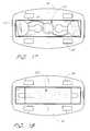
- FIG. 2is a perspective view of the anchoring system of FIG. 1 shown with the covers in a closed position;
- FIG. 3is a perspective view of the anchoring system of FIG. 1 illustrated with the covers in the open position and an exemplary catheter illustrated by phantom lines in an inserted position within the retainer;
- FIG. 4is a perspective view of the anchoring system of FIG. 3 shown with the covers in the closed position and the exemplary catheter (again shown in phantom lines) positioned in and retained by the retainer;
- FIG. 5is a top plan view of the base and covers of the retainer of FIG. 1 shown with one cover in the open position and one cover in the closed position;
- FIG. 6is a cross sectional side view of the retainer of FIG. 5 taken along line 6 — 6 ;
- FIG. 7is a front elevational view of the retainer of FIG. 5;
- FIG. 8is an enlarged view of the area encircled by line 8 — 8 of FIG. 5 and illustrates the structure of a post opening within the base of the retainer;
- FIG. 9is a front elevational view of a post platform of the retainer of FIG. 1;
- FIG. 10is a side elevational view of the post platform of FIG. 9;
- FIG. 11is a top plan view of the post platform of FIG. 9;
- FIG. 12is a top plan view of the assembled retainer of FIG. 1, including the base, covers and post platform, shown with an exemplary catheter in the channel of the retainer and the covers in the open position;
- FIG. 13is a front plan view of another post platform using fixed position posts, suitable for use with the base and cover of FIG. 1;
- FIG. 14is a side elevational view of the fixed post platform of FIG. 13;
- FIG. 15is a top plan view of the fixed post platform of FIG. 13;
- FIG. 16is a cross-sectional view of the fixed post platform of FIG. 15 taken along line 16 — 16 ;
- FIG. 17is a bottom plan view of the assembled retainer of FIG. 1, showing the placement of the movable post platform of FIG. 9 within the groove of the retainer base;
- FIG. 18is a bottom plan view of an assembled retainer using the fixed post platform of FIG. 13 within the groove of the retainer base;
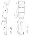
- FIG. 19is a perspective view of an anchoring system in accordance with an additional preferred embodiment of the present invention including a fixed post and a movable post, with the cover in a closed position;
- FIG. 20is a perspective view of the anchoring system of FIG. 19 shown with the cover in an open position;
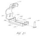
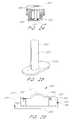
- FIG. 21is an exploded perspective view of the retainer of FIG. 19, illustrating the movable post detached from the retainer;
- FIG. 22is a front elevational view of the retainer of FIG. 19, with the cover shown in a fully open position;
- FIG. 23is a top plan view of the retainer of FIG. 22, with the cover fully open;
- FIG. 24is a cross-sectional view of the retainer taken along line 24 — 24 of FIG. 19 showing the movable post within a track of the retainer;
- FIG. 25is a perspective view of the movable post of FIG. 21;
- FIG. 26is a front plan view of the assembled retainer of FIG. 19 with the cover shown in the closed position;
- FIG. 27is a top plan view of the retainer of FIG. 19 shown in the fully open position with an exemplary catheter shown inserted into the channel of the open retainer;
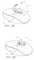
- FIG. 28is a perspective view of the anchoring system of FIG. 19 shown with the cover in a partially open position and with an exemplary catheter shown in phantom lines within the channel of the retainer;
- FIG. 29is a perspective view of the anchoring system of FIG. 28 shown with the cover in a closed position;
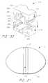
- FIG. 30is a partial, perspective view of the latching mechanism of the retainer of FIG. 19 shown in a partially open position.
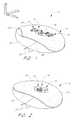
- FIG. 31is a bottom plan view of the anchor pad, showing a release liner.
- the present embodiment of the catheter anchoring systemwhich is generally designated by reference numeral 10 , is disclosed in the context of use with an exemplary CVC (as shown in FIG. 3 and designated by reference numeral 12 ).
- the principles of the present inventionare not limited to catheters. Instead, it will be understood by one of ordinary skill in this art, in view of the present disclosure, that the anchoring system and/or retainer disclosed herein also can be successfully utilized in connection with other types of medical articles, including, but not limited to, other types of catheters, fluid drainage and delivery tubes and electrical wires.
- the retainer disclosed hereinalso can be configured to receive and secure peripheral catheters, peripherally inserted central catheters, hemodialysis catheters, surgical drainage tubes, feeding tubes, chest tubes, nasogastric tubes, scopes, as well as electrical wires or cables connected to external or implanted electronic devices or sensors.
- peripheral cathetersperipherally inserted central catheters
- hemodialysis catheterssurgical drainage tubes
- feeding tubeschest tubes
- nasogastric tubesscopes
- electrical wires or cables connected to external or implanted electronic devices or sensorsare also find additional applications for the devices and systems disclosed herein.
- the illustration and description of the anchoring system in connection with a CVCis merely exemplary of one possible application of the anchoring system.
- Each of the embodiments described hereinemploys some basic concepts characteristic of the present anchoring system, namely releasable engagement of the catheter to the patient.
- the releasable engagementis achieved by cooperation among a base, at least one cover and at least one post element.
- This cooperationallows the catheter to be disconnected from the anchoring system and from the patient, for any of a variety of known purposes.
- the healthcare workermay want to remove the catheter from the anchoring system to ease disconnection of the catheter from the insertion point or to clean the patient.
- the disengagement of the catheter from the anchoring systemcan be accomplished without removing the anchoring system from the patient.
- the present anchoring systeminhibits axial movement of the catheter with respect to the anchoring system, and hence, with respect to the insertion site on the patient.
- Transverse and lateral movementis generally arrested by the holding effect provided by the base and cover assembly, as well as by the cooperative interaction between at least one post member and an opening on the catheter and/or catheter fitting. That is, the base and cover assembly surround the catheter while the post(s) extends through a corresponding suture or mount opening(s) formed on the catheter and/or catheter fitting. Longitudinal movement is similarly arrested by the interaction between the post(s) and the opening(s).
- the present anchoring systemalso is adapted to receive at least several different types or styles of catheters and/or catheter fittings.
- the spacing between the posts and/or the spacing between a post and either the cover assembly or basecan be varied in order to accommodate catheters and/or catheter fittings with differing spacings between the suture holes.
- This featurecan also be used to accommodate catheters and/or catheter fittings having different sizes and/or shapes.
- the retainerincludes two posts, each of which is movable with respect to the other and also with respect to the cover assembly and the base of the retainer. In another embodiment, one of the posts is fixed and the other is movable.
- the spacing between the posts, as well as the spacing between the movable post and the adjacent base/cover structure,can be varied by moving the one post.
- the post(s)can be fixed to a cover or base section which can move relative to another section of the retainer to changes the position of the post(s) on the retainer. So configured, the lateral width between posts can be adjusted to receive and secure a variety of catheters and/or catheter fittings.
- Various other aspects of the present inventioncan be used apart from this “universal” feature, as will be apparent from the discussion of the embodiments below.
- a “longitudinal axis”is generally parallel to the section of the catheter 12 retained by the anchoring system 10 .
- a “lateral axis”is normal to the longitudinal axis and is generally parallel to the plane of the anchor pad 14 .
- a “transverse axis”extends normal to both the longitudinal and lateral axes.
- the longitudinal directionrefers to a direction substantially parallel to the longitudinal axis; “the lateral direction” refers to a direction substantially parallel to the lateral axis; and “the transverse direction” refers to a direction substantially parallel to the transverse axis.
- proximal and distalare used consistently with the description of the exemplary applications. Thus, proximal and distal are used in reference to the center of the patient's body.
- the terms “upper,” “lower,” “top,” “bottom,” and the like, which also are used to describe the present anchoring system 10are used in reference to the illustrations of the embodiments. A detailed description of the anchoring system 10 , and its associated method of use, now follows.
- the anchoring system 10is constructed in accordance with a preferred embodiment of the present invention.
- the systemcomprises an anchor pad 14 and a retainer 16 that includes a base 18 , a cover assembly 19 and at least one post.
- the postis part of a post platform that is attached to the retainer base 18 when the retainer 16 is assembled.
- the postas noted below, can be part of the base 18 and/or the cover assembly or be a separate individual piece.
- the retainer 16is configured to accept and to retain and secure a section of a catheter 12 (shown in FIG. 3) within the anchoring system 10 .
- the same arrangementcan be used to secure a detachable catheter fitting which is attached to a catheter to be retained, as described below.
- the catheter 12 or fittingis inserted into the base 18 of the retainer 16 while the cover assembly 19 is in an open position, as shown in FIG. 3 .
- the cover assembly 19 in the present embodimentcomprises two separate covers 20 , 22 , each independently attached to the base 18 .
- the covers 20 , 22are moved into a closed position over the base 18 and catheter 12 to inhibit transverse motion of the catheter 12 . This can be seen in FIG. 4 .
- the catheter 12 or fittingalso is retained laterally and longitudinally by its interaction with one or more posts of the retainer 16 and by its interaction with the surrounding sections of the base 18 and/or the covers 20 , 22 .
- the retainer 16is disposed upon an upper surface of the anchor pad 14 .
- the lower side 23 of the anchor pad 14includes an adhesive surface which adheres to the skin of the patient in order to maintain the position of the retainer 16 , and hence the catheter 12 , with respect to the patient.
- the anchor pad 14is a substantially flat piece of material with transversely opposing sides.
- the proximal or lower side 23 of the padfaces toward the skin of the patient, and is preferably covered with an adhesive surface suitable for attaching the anchor pad 14 to the skin of the patient.
- the upper or distal side 24 of the padfaces away from the skin of the patient and supports the retainer 16 .
- the anchor pad 14preferably comprises a laminate structure with an upper foam layer (e.g., closed-cell polyethylene foam) and a lower adhesive layer.
- the lower adhesive layerconstitutes the lower surface 23 of the anchor pad 14 .
- the lower surface 23desirably is a medical-grade adhesive and can be either diaphoretic or nondiaphoretic, depending upon the particular application.
- foam with an adhesive layeris available commercially from Tyco Adhesives of Norwood, Mass.
- a surface of the upper foam layerconstitutes the upper surface 24 of the anchor pad 14 .
- the upper surface 24can be roughened by chemical priming or corona-treating the foam with a low electric charge.
- the roughened or porous upper surface 24can improve the quality of the adhesive joint (which is described below) between the base 18 and the anchor pad 14 .
- the flexible anchor pad 14can comprise a medical-grade adhesive lower layer, an inner foam layer and an upper paper or other woven or nonwoven cloth layer.
- a removable paper or plastic release liner 26desirably covers the adhesive lower surface before use.
- the liner 26preferably resists tearing and desirably is divided into a plurality of pieces to ease attachment of the pad to a patient's skin.
- the lineris split along a centerline 28 of the flexible anchor pad 14 in order to expose only half of the adhesive lower surface at one time.
- each liner pieceextends beyond the centerline 28 of the anchor pad 14 and is folded over, or back onto the liner.
- This folded over portiondefines a pull-tab 30 to facilitate removal of the liner piece 26 from the adhesive lower surface.
- a healthcare workeruses the pull-tab 30 by grasping and pulling on it so that the liner piece 26 is separated from the lower surface.
- the pull-tabeliminates the need to pick at a corner edge or other segment of the liner in order to separate the liner from the adhesive layer.
- the pull-tab 30of course can be designed in a variety of configurations.
- the pull-tabneed not be located along a centerline of the anchor pad 14 ; rather, the pull-tab can be located along any line of the anchor pad 14 in order to ease the application of the anchor pad 14 onto the patient's skin at a specific site.
- an area of a patient's skin with an abrupt bend, such as at a joint,can require that the pull-tab be aligned toward one of the lateral ends of the anchor pad 14 rather than along the centerline.
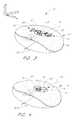
- the anchor pad 14also preferably includes a concave section 32 that narrows the center of the anchor pad 14 proximate to the retainer 16 .
- the anchor pad 14is formed generally into a crescent shape that includes a concave section 32 on one side of the retainer and a convex section 34 on the other. This shape permits the pad 14 to be placed on the patient such that the arms of the crescent extend away from the insertion site.
- the retaineris preferably centered upon the anchor pad 14 about an axis which bifurcates the crescent shape. Consequently the lateral sides of the anchor pad 14 have more contact area, both forward and rearward of the retainer 16 in the longitudinal direction, which provides greater stability and adhesion to a patient's skin while still permitting the retainer 16 to be located near the insertion site.
- the anchor pad 14also can include suture and/or breather holes to the sides of the retainer 16 .
- the base 18 and the cover assembly 19principally define the retainer 16 .
- the cover assembly 19in the illustrated embodiment, comprises two covers 20 , 22 , each of which is connected to the base at a folding hinge 36 .
- This arrangementallows the base 18 and the covers 20 , 22 to be formed as a unitary piece. This can be accomplished by any of a variety of ways well known to those skilled in the art.
- the base 18 and the cover assemblycan be injection molded in order to reduce fabrication costs. As shown in FIG. 5, one cover 20 is in a closed position, while the other cover 22 is in an open position.
- cover assembly and base 18are desirably flexible.
- Suitable materials which are both sufficiently strong but flexibleinclude without limitation: plastics, polymers, or composites such as polypropylene, polyethylene, polycarbonate, polyvinylchloride, acrylonitrile butadiene styrene, styrene butadiene, nylon, olefin, acrylic, polyester, moldable silicon, thermoplastic urethane, thermoplastic elastomers, thermoset plastics and the like.
- the retainer 16is preferably formed by injection molding using a styrene butadiene polymer, such as KRO3 resin, available commercially from Phillips Petroleum of Houston, Tex. However, other materials can be used, and the retainer can comprise a multi-piece base or cover as well.
- the base 18includes an elongated body of a generally hollow, generally parallelepiped shape.
- the base 18can be configured in a variety of shapes, however, such as circular, square, or trapezoidal, in order to suit a particular application.
- the base 18may be configured to generally match the shape of the anchor pad 14 (shown in FIG. 1) or the shape of the winged catheter fitting (not shown).
- a parallelepiped shapeis preferably used to allow the base 18 and covers 20 , 22 to be integrally formed and to capture the somewhat rectangular shape of the catheter fitting wings (see FIG. 12 ).
- a bottom wall 37 of the base 18includes a substantially flat bottom surface 38 with the exception of a recess 40 that extends upward.
- the recess 40extends laterally from one lateral side of the base 18 to the other along the bottom side 38 of the base 18 , and has a longitudinal width and transverse depth sufficient to receive the post(s) and/or a post platform, as described below.
- the base 18also includes one or more openings to facilitate connection of the post(s) (described below) to the base 18 . These holes extend through the bottom wall 37 of the base 18 and open into a hollow receiving space 42 defined within the retainer 16 . In the illustrated embodiment, a central circular opening 44 is formed in the center of the recess 40 ; however, this opening can be disposed at other locations on the base 18 .
- the retainer 16includes at least one post, which in some modes of the invention is movable relative to the base 18 .
- the base 18accordingly includes at least one additional opening to receive the post.
- This openingcan have a complementary shape to that of the post or can be enlarged relative to or have a different geometry than the shape of the post.
- the openingdesirably has a shape that is elongated in at least one direction so as to allow the post to move in such direction.
- the base 18includes two additional openings 46 to receive two posts. While only a single post and hence a single opening is required, the illustrated embodiment uses two posts and two openings. Each post opening 46 is provided for a corresponding post such that the corresponding post protrudes through the bottom wall 37 of the base 18 when the retainer 16 is assembled.
- the retainer 16can include more than two post-opening pairings in some applications of the present anchoring system, as will be understood by one of ordinary skill in the art.
- each post opening 46 in the illustrated embodimentincludes a substantially circular region 48 and an elongated slot 50 extending from the substantially circular region 48 .
- the substantially circular region 48has a diameter larger than the width of the elongated slot 50
- the elongated slot 50has a width larger than the diameter of the corresponding post.
- the present embodimentis configured with the slot 50 extending from the circular region 48 in a lateral direction in order to accommodate differing lateral spacing between mounting holes among different catheters or catheter fittings. As noted previously, however, these slots could also extend longitudinally or in a direction skewed relative to the longitudinal and lateral axes in order to suit a particular application. Also, the slot 50 in the illustrated embodiment extends from the substantially circular region 48 outwardly relative to the center of the base 18 , but the circular region 48 can be located at other positions along the corresponding slot 50 (e.g., at the outer lateral end of the slot). In addition, more than one slot can extend from the circular region 48 .
- one edge of the slothas a scalloped shape.
- Each scallophas a radius of curvature generally matching a radius of a corresponding post that slides through the slot 50 .
- the distance D between the lateral end point 52 of each scallop and the opposing edge of the slot 50preferably is less than a diameter of the corresponding post so as to inhibit unintentional movement of the post within the slot 50 , as described below.
- the base 18includes upstanding front and back walls 54 , 56 that are spaced from the central opening 44 in the longitudinal direction, and extend upward from the lower wall 37 of the base 18 .
- An opening 58 , 60generally bifurcates each wall 54 , 56 , respectively, to allow the catheter to pass through one wall 54 , through the receiving space 42 and above the lower wall 37 of the base 18 , and then out the opposite wall 56 .
- Sidewalls 62 , 64 of the base 18are spaced lateral from the central opening 44 and extend upward from the lower wall of the base 18 . These sidewalls 62 , 64 are continuous with the front and back walls 54 , 56 of the base. The corners between the sidewalls 62 , 64 and the front and back walls 54 , 56 preferably are rounded.
- the base 18has an open upper end that is generally defined by the upper edges of the walls 54 , 56 , 62 , 64 .
- the retainer 16does have a generally rectangular box-like shape without an upper wall and with the central openings 58 , 60 formed in the front and back walls 54 , 56 .
- the base 18also includes holes 66 which allow portions of the front and rear walls 54 , 56 of the base 18 to flex in a longitudinal direction more easily. This feature is advantageous to the operation of the latching mechanism, described below.
- the longitudinal, lateral and transverse dimensions of the retainer 16desirably are as small as possible, while still receiving and stabilizing the catheter 12 , including its wings.
- the longitudinal dimension of the base 18which is defined between the front and back walls 54 , 56 , preferably is long enough to stabilize the retained length of catheter 12 . That is, the length of catheter 12 which is secured within the retainer 16 , is sufficient to inhibit rocking of the catheter 12 relative to the retainer 16 .
- the longitudinal dimension of the base 18also is sufficient to receive the largest length of catheter wings for which the retainer 16 is designed.
- the lateral dimension of the base 18which is defined between the sidewalls 62 , 64 , similarly is sized to accommodate the largest width of catheter wings for which the retainer 16 is designed. It is also preferred that the lateral dimension be sufficient to provide a convenient and natural grip of the base 18 of the retainer 16 while manipulating the covers 20 , 22 and/or posts of the retainer 16 .
- the lateral dimensionalso preferably provides sufficient width to mount hinges and latch mechanisms in the present embodiment, as described below.
- the transverse height of the base 18preferably corresponds to the thickest catheter wing for which the retainer 16 is designed. While the catheter body may have a larger size than its wing thickness, the base 18 accommodates this through its open central region between the covers 20 , 22 . The base 18 thus needs not have a greater transverse height than that of the catheter 12 , and consequently, the profile of the retainer 16 is minimized.
- the receiving space 42is formed on the base 18 between the lateral walls 62 , 64 of the base 18 .
- the receiving space 42is desirably formed so as to accept and retain a portion of the catheter or catheter fitting, and in particular the wings thereof, without occluding the lumen of the catheter.
- the covers 20 , 22have a size and shape that desirably is coextensive with the longitudinal dimension of the base 18 .
- each cover 20 , 22preferably extends longitudinally at least as far as the base does, the cover 20 , 22 need not span the entire lateral dimension of the base. This will be discussed below. In some modes it is desirable for the covers 20 , 22 to be larger longitudinally than the base 18 .
- the covers 20 , 22can also include a flange 68 that is useful in operation of the latch mechanism of the cover. This will be discussed below. In other modes, the cover need not include the flanges 68 .
- Each cover 20 , 22preferably is connected to the base 18 by at least one hinge 36 to provide each cover 20 , 22 with at least two positions: an open position, in which the receiving area 42 of the base 18 is exposed and into which a catheter or fitting may be inserted; and a closed position, in which the cover 20 , 22 is located over the base 18 and covers at least a portion of the receiving area 42 .
- the covers 20 , 22are held in place by a latch mechanism, described below, to inhibit the unintentional transverse release of the catheter or catheter fitting from the receiving area 42 of the base 18 .
- the coversdesirably are sufficiently sized to accommodate the necessary latch mechanism components and to extend over or around at least a portion of the posts 70 (and possibly receive upper ends of the posts) when in the closed position.
- the interaction between the upper portions of the posts 70 and the covers 20 , 22inhibits movement or play of the post upper ends relative to the covers 20 , 22 . Consequently, this interaction inhibits the posts 70 from deflecting or bending, at least in the longitudinal direction, when the catheter is tugged to maintain a secure connection between the posts 70 and the catheter 12 .
- each cover 20 , 22 of the cover assembly 19has a hinge 36 and a latch mechanism, such that each cover can be independently placed into an open or a closed position.
- the covers 20 , 22do not contact one another when both are in the closed position, as shown in FIGS. 2 and 4.
- both coversextend from the lateral sides 62 , 64 of the base 18 toward the center of the retainer 16 , by reducing the lateral dimension of the covers 20 , 22 such that the components do not interact when closed, it becomes possible to effectively secure catheters or fittings that extend transversely beyond the height which could be contained below the covers if the covers were to meet.
- the anchoring system 10is more universal and has a lower profile as noted above.
- An example of how the retainer 16 and posts hold a catheter 12is shown in FIG. 4 .
- a recess 72is formed which will lie over the post opening 46 on the corresponding half of the base 18 when the cover is in the closed position.
- This recess 72preferably extends from a point directly above the substantially circular region 48 of the post opening 42 and along the length of the elongated slot 50 of the corresponding post opening.
- the recess 72desirably is deep enough and wide enough along its length to freely receive the upper end of the corresponding post 70 , which protrudes through the corresponding post opening 46 , such that the post 70 does not interfere with the movement of the cover 20 , 22 into the closed position.
- the recess 72also receives the upper end of the post 70 when the cover 20 , 22 is closed to inhibit the post 70 from bending in the longitudinal direction.
- the post 70can extend through the cover 20 , 22 without interfering with movement of the cover and with the cover capturing a portion of the post to inhibit bending of the post in the longitudinal direction.
- each hinge 36preferably comprises a flexible band that can take any number of forms to mechanically connect the cover 20 , 22 to the base 18 while permitting pivotal movement of the cover 20 , 22 relative to the base 18 so as to enable engagement or disengagement of these parts, as described below.
- the bandis formed of flexible material, desirably of the same material from which the base 18 and cover 20 , 22 are comprised.
- the hinges 36are integrally molded with the base 18 and the covers 20 , 22 to form a unitary member, as noted above.
- the hinges 36are located at an outer edge of the base 18 and the cover assembly 19 ; however, the hinges 36 need not be laterally located at an extreme end of the base 18 or cover assembly 19 .
- the illustrated embodimentshows the hinges 36 positioned near the same plane as the upper edges of the base 18 for ease of manufacture.
- the width of the hinges 36is desirably less than that of either the base 18 or the covers 20 , 22 to allow some leeway or play when engaging or disengaging the cover 20 , 22 to the base 18 . That is, this shape allows the hinge 36 to twist to some degree to compensate for some manufacturing tolerances; however, the hinges can have at least as large of a longitudinal dimension as the base 18 and/or the covers 20 , 22 .
- the hinges 36are desirably integrally formed along common corresponding exterior surfaces of the covers 20 , 22 and base 18 .
- Each hinge 36has a generally U-shape 74 when the cover is closed, and extends from both the base 18 and the cover 20 , 22 in the lateral direction to the side of the retainer 16 .
- a gap, corresponding to a transverse height of the hinge 36exists between the base 18 and covers 20 , 22 . This gap, however, can be reduced or eliminated from the retainer for some applications by using a different hinge design.
- the hinges 36enable each cover 20 , 22 to move between the open position and the closed position.
- the open positionshown by cover 22 in FIGS. 5 and 7, is characterized by exposing the corresponding post in the transverse direction.
- the retainer 16is capable of receiving a portion of the catheter 12 .
- the closed positionshown FIGS. 4, 5 and 7 , is characterized by the cover 20 lying in contact or in near contact with the base 18 so as to position the post within the recess 72 in the cover 20 .
- both covers 20 , 22are in the closed position, as shown in FIG. 4, the retainer 16 surrounds the received portion of the catheter 12 .
- the hinges 36need not provide 180° of movement for the covers 20 , 22 relative to the base 18 to establish a closed position and a fully open position.
- the hinges 36can permit a smaller degree of movement (e.g., 90°) between the base 18 and the covers 20 , 22 while still providing enough space to transversely insert the catheter 12 into the retainer 16 when both covers 20 , 22 are open.
- the base and coverinclude structures that interengage when the covers are in the closed position.
- a latch mechanism 80is provided for securing the covers 20 , 22 in the closed position relative to the base 18 .
- the latch mechanism 80comprises at least one movable keeper 82 and at least one latch 84 .
- the keeper 82is disposed on the cover 20 while the latch 84 is disposed on the base 18 .
- the keepercan be disposed on the base and the latch can be disposed on the cover.
- Each keeper 82extends from the cover 20 toward the base 18 of the retainer 16 from the lower side of the cover 20 (“lower” as seen when the cover is in the closed position as in FIG. 6 ).
- each keeper 82has at the end farthest from the cover a tang 86 that extends in the direction toward the corresponding latch 84 .
- This tang 86is rounded as seen in FIG. 6; however, the tang can have a surface that lies generally normal (e.g., ⁇ 15° from perpendicular) to the transverse axis.
- the latch 84comprises a protrusion 88 that is formed on the base 18 at a location that will interact with the tang 86 of the keeper 82 when the cover 20 is in the closed position. This can be seen in FIG. 6 .
- a protrusion 88is formed on the front and back walls 54 , 56 of the base 18 .
- the latch 84is located along the wall 54 , 56 of the base at a position adjacent to a hole 66 in the base 18 . By positioning the latch 84 at such a location, it is more able to flex in the longitudinal direction. This is because the hole 66 reduces the resistance of the base 18 in that region to deformation.
- the lower side of the protrusion 88preferably has a complimentary shape to that of the top of the tang 86 to promote engagement between them when the cover is closed.
- the protrusion 88is preferably rounded in the same manner as the tang 86 of the keeper 82 .
- the protrusionhas a generally flat lower surface that is upwardly included at about 10° relative to the plane of the bottom wall 37 and the upper surface of the tang 86 has a similar complimentary surface that slopes downward by 10°.
- the keeper 82In order to allow disengagement of the latching mechanism 80 , it is necessary for the keeper 82 to flex as the tang 68 moves past the protrusion 88 of the latch 84 . In one mode of operation, this can be accomplished by pressing upon a flange 68 or other extension of the cover 20 . By pressing upon the flange 68 , the cover 20 bends, moving the tang 86 of the keeper 82 away from the protrusion 88 of the latch 84 , and allowing the cover 20 to be moved out of the closed position without exerting excessive force upon the cover. Desirably, such a flange 68 is formed integrally with the cover 20 of the retainer 16 . The reduced thickness of the cover 20 along its center section, which is created by the recess 72 , aids in the cover bending in this manner.
- each cover 20 , 22also includes an overhang 90 formed on its inner edge (i.e., the edge closest to the central opening 44 ).
- This overhang 90preferably is sized to allow the fingertip or fingernail of the healthcare worker to slip underneath the overhang to pull up the cover 20 , 22 in another mode of opening the cover.
- the upward force appliedcauses the tang 86 to slide over the protrusion 88 to disengage the latching mechanism 80 .
- the overhang 90provides another way to open the cover 20 , 22 .
- each cover 20 , 22has two keepers 82 , requiring two latches 84 on the base.
- the latch mechanisms 80 on each coverare formed as mirror images of each other.
- the postsmay be formed as part of a post platform 92 .
- An embodiment of the post platform 92which includes a plurality of movable posts 70 , is illustrated in FIGS. 9, 10 and 11 .
- the post platform 92includes an attachment button 94 for connecting the platform 92 to the base 18 , posts 70 that are configured to extend through the post openings 46 in the base 18 , and connectors 96 which at least initially hold the posts 70 to the attachment button 94 .
- the platform 92is attached to the base 18 from below by aligning the attachment button 94 with the central opening 44 in the base 18 , inserting the posts 70 through the post openings 46 , and pressing the platform 92 upward into the recess 40 on the lower side of the base 18 .
- the larger radius on the upper portion of the attachment button 94will snap into position in the central circular opening 44 .
- the upper portion of the attachment button 94can be disposed within a countersink formed on the upper side of the bottom wall 37 . The pair of posts 70 then protrudes through the post openings 46 of the base, and may move laterally within the lateral extent of their respective post openings 46 in the base 18 .
- the attachment button 94comprises a cylindrical peg of a diameter to allow it to be inserted through the central circular opening 44 of the base 18 from the lower, or proximal, side.
- a distal portion of the cylindrical peghas a larger radius than the proximal portion of the attachment button. This upper portion is also of slightly larger radius than the central circular opening 44 in the base 18 .
- the upper edge of the attachment button 94is preferably chamfered to allow the button to be easily inserted through the central circular opening 44 of the base. Once inserted into the central circular opening, the larger radius at the distal portion of the button 94 will prevent the button from being pulled out of the base 18 in the proximal direction.
- the connectors 96illustrated in FIG. 11, comprise extensions from the lowest portion of the attachment button 94 which extend laterally therefrom and connect to the lowest portion of the posts 70 . Desirably, these connectors 96 allow the distance at which the posts 70 are disposed from the attachment button 94 to vary after the retainer is assembled.
- Each connector 96comprises a leash that extends parallel to the base 18 of the retainer away from the attachment button 94 at an angle to the lateral direction.
- the leashcan be straight when fully extended or can follow a semi-looped or curved path. This path can also assume a zigzag or similar shape.
- the shape of the leashallows the lateral extension of the leash to be adjusted by permitting the leash to flex.
- each connector 96can have enough flexibility to allow it to remain intact while spanning distances ranging from the farthest lateral position in the post opening 46 , to the minimum lateral distance defined by the circular portion 48 of the post opening.
- the leashescan be configured to bias the posts 70 inward or outward. In another variation, however, once the posts 70 are assembled in the base, the posts do not need to be tethered together, and the leashes can be designed to break after assembly.
- the posts 70are disposed at the lateral end of each connector 96 .
- the posts 70comprise substantially cylindrical members that extend transversely in the distal direction from a lowest portion that is attached to the corresponding connector 96 of the post platform 92 .
- the posts 70desirably also include a flange 98 , located distally along the length of the cylinder such that it will lie above the bottom wall 37 of the base 18 when the platform 92 is inserted into the retainer base 18 .
- This flange 98is preferably sized to have a radius larger than the radius of the elongated slot 50 portion of the post opening 46 , but smaller than the circular section 48 of the post opening 46 .
- the flange 98can be inserted through the circular section 48 of the post opening 46 along with the post 70 , and then remain above the base 18 of the retainer when the post 70 is moved to a position along the length of the elongated slot 50 .
- the flange 98stabilizes the post 70 and maintains its proper orientation with regard to the base 18 , i.e., the flange 98 maintains the post 70 in a transversely upright position and inhibits significant rocking of the post.
- the circular region 48 of the post opening 46is located at the innermost lateral position that a post 70 would be desirably located, and the track 50 extends to the outermost lateral position that a post 70 would be desirably located.
- the postBy moving the post laterally, it can be positioned as desired at any location along the length of the slot 50 .
- the series of protrusions or scallop end points 52which extend into the slot 50 and effectively narrow the width of the slot at the position of each protrusion 52 , as noted above.
- the width of the slot 50is comparable to, or slightly narrower than, the width of the posts 70 which will extend through the post opening 46 . This arrangement provides a ratcheting action for positioning the post 70 at the desired location, and then retaining the post at said location.
- the material of the base 18 and post 70are slightly elastic, it is possible to push the post along the slot 50 past a protrusion 52 into the section of the slot that is wider between the protrusions, even if the width of the slot at the protrusion is slightly narrower than the diameter of the post 70 .
- the protrusions 52will inhibit unintended lateral motion of the post 70 from its location. This ratcheting arrangement allows effective positioning of the posts 70 to any desired lateral position between protrusions 52 without undesirable inadvertent motion of the posts once positioned.
- the number of posts 70 shown in the instant embodimentis two, any number of posts may be used to accommodate a specific purpose. For example, if a particular catheter fitting contained four holes, a retainer designed to retain that fitting would desirably have four posts extending through four post openings in the base of the retainer. Similarly, if a “Y” shaped catheter or fitting was to be retained, three posts could be used to provide the desired stability.
- the post 70 and/or the post platform 92can be formed from a variety of materials using various known manufacturing methods.
- the post 70 and/or post platform 92can be injected molded. Suitable materials for such include without limitation: plastics, polymers, or composites such as polypropylene, polyethylene, polycarbonate, polyvinylchloride, acrylonitrile butadiene styrene, styrene butadiene, nylon, olefin, acrylic, polyester, moldable silicon, thermoplastic urethane, thermoplastic elastomers, thermoset plastics and the like.
- the posts and post platform 92are preferably formed by injection molding using a nylon, such as Zytel 101 L, available commercially from E.I. du Pont Company of Wilmington, Del. However, other materials can be used, and the post platform can comprise a multi-piece assembly.
- the retainer 16then is attached to the upper surface 24 of the anchor pad 14 .
- the base 18desirably is secured to the upper surface 24 by a solvent bond adhesive, cyanoacrylate or other bonding material.
- a solvent bond adhesiveis available commercially as Part No. 4693 from the Minnesota Mining and Manufacturing Company (3M).
- a UV cured adhesivealso can be used, as known in the art. It is important when attaching the base 18 to the anchor pad 14 that the post platform 92 is not secured to the anchor pad as well.
- the posts 70 in this modemust be free to slide within the recess 40 on the underside of the base 18 and within the post openings 46 for the posts 70 to be properly movable between different desired locations.
- the anchoring system 10can optionally include a fitting for mounting the catheter to the retainer 16 .
- the fittingcan take the form of a conventional box clamp and a soft wing clamp. Box clamps and soft wing clamps are commercially available from Arrow® for use with its CVC. Other clamps with suture wing extensions are currently in commercial use with Quinton® Hemodialysis catheters, Cook® PICC's, Baxter® CVCs and B. Braun® CVCs. Those skilled in the art will find application for the present invention with any of these or other clamp configurations.
- the fittingcan also be replaced with an inter-line connector or adaptor, such as those used to connect the catheter to a supply, delivery or drainage line.
- the receiving space 42 formed between the base 18 and covers 20 , 22 when they are in the closed positiondefines a channel.
- the channelis capable of receiving a portion or length of the catheter and is generally configured to house, grip and secure the affected catheter portion.
- the channelhas a generally symmetrical shape. However, other cross-sectional shapes may be used for particular applications, such as for supporting a Y-site catheter.
- the length of the channelis desirably sufficient in the longitudinal direction to stabilize the catheter, rather than acting as a fulcrum for the catheter, as was discussed above. That is, the retainer 16 receives a sufficient length of the catheter to inhibit movement of the catheter in the lateral, longitudinal and transverse direction (i.e., to inhibit yaw, pitch and axial movement of the catheter), without kinking the catheter.
- the internal width of the channelcan be varied by adjusting the position of the posts 70 . By moving or sliding the posts along their slots 50 , the distance between the posts can be varied. This is especially important when the anchoring system 10 is used with a wide variety of catheters and catheter fittings that may not have similar juncture configurations or suture hole spacing.
- the retainer 16at least restricts, if not prevents, transverse and lateral movement of the retained section of the catheter. Transverse movement is also restricted when the covers 20 , 22 are open by the height of the posts 70 , which inhibit upward migration of the catheter 12 and/or catheter fitting. Inhibiting movement of the catheter in the longitudinal direction when the catheter 12 is secured within the retainer 16 is desirably accomplished by the posts 70 and holes.
- the covers 20 , 22are moved toward the closed position.
- the relatively thin strip of material forming the hinge 36allows the hinge to bend when finger pressure is exerted on the covers to close them.
- the tangs 86 at the end of the keepers 82contact the protrusions 88 of the latches 84 on the base 18 when the covers 20 , 22 near their closed position.
- Continued pressureforces the keepers 82 inward (toward each other) to permit the tangs 86 to pass beyond the protrusions 88 .
- the tangs 86snap over the protrusions 88 under the spring force provided by the deflected keepers 82 when the covers 20 , 22 sit atop the base 18 .
- the interaction between the tangs 86 and the corresponding surfaces of the latches 84hold the covers in this position.
- a healthcare workerpresses inwardly on the protruding flanges 68 of the covers 20 , 22 or lifts up the covers 20 , 22 , as described above.
- the resulting inwardly directed forcedeflects the keepers 82 and moves the tangs 86 inward to clear the protrusions 88 of the latches 84 .
- the healthcare workercan then open the covers and expose the posts 70 and the base 18 .
- This releasable engagement between the covers 20 , 22 and the base 18allows the same retainer 16 to be used for an extended period of time, while permitting repeated attachment and reattachment of the catheter 12 or fitting to the anchoring system 10 .
- the hinges 36 which connect the covers 20 , 22 to the base 18ensure that the covers will not be lost or misplaced when the catheter 12 is detached from the anchoring system 10 .
- the healthcare workerwastes no time in searching for a misplaced cover, or in orienting a cover prior to latching, and he or she is not required to carry a separate instrument to detach the catheter from the anchoring system.
- a healthcare workermay secure a catheter (or other medical article) to a patient using the above-described anchoring system (or a readily apparent modification thereof).
- the healthcare workerfirst opens the retainer 16 to expose the posts 70 .
- a catheter 12may be transversely aligned over the posts 70 , as shown in FIG. 3 and FIG. 12 .
- the catheter 12may then be placed into the channel formed between the posts 70 .
- openings formed on either the catheter 12 or a fittingcan then be slid over the posts to further secure the catheter to the retainer 16 .
- the covers 20 , 22are closed and latched in the manner described above, as seen in FIG. 4 .
- the holding effect of the posts 70 and holesprevent the catheter from pulling through the retainer 16 .
- the retainerthus inhibits longitudinal movement of the catheter relative to the retainer.
- Interaction between the base 18 , covers 20 , 22 , posts 70 and holesrestrict movement of the catheter 12 in the transverse and lateral directions.
- the interaction between the posts 70 and the covers 20 , 22also inhibits significant bending of the post upper ends in the longitudinal direction which, if allowed, would permit the catheter to slide off the posts.
- the base 18 and covers 20 , 22do not crimp or kink the catheter body when it is inserted within the channel and about the posts 70 . Moreover, although the posts do bear against the catheter body, their limited pressure does not significantly occlude the corresponding catheter lumen(s).
- a variation to that described aboveis produced using the same anchor pad 14 , base 18 and covers 20 , 22 , but substituting a different post platform 100 for that described above.
- the post platform of this alternate embodimentdoes not provide for movable posts; the posts are in fixed positions on the platform, and therefore, the user cannot adjust the spacing of the posts.
- FIGS. 13 to 16An example of a post platform 100 consistent with the present embodiment can be seen in FIGS. 13 to 16 .
- the platform 100still consists of connectors 102 , an attachment button 104 , and posts 106 .
- the connector 102instead of the connectors being flexible leashes that allow the distance between the post 106 and the attachment button 104 to be adjusted, the connector 102 comprises a lateral extension of the lowest portion of the attachment button 104 that also acts as the lowest portion of each post 106 . Because there is no need for flexibility, the geometry of the connector is simplified.
- This fixed post arrangementalso provides for greater stability for the posts 106 than the movable position post platform 92 does. It is most significant to note that in such an embodiment there is no need for the flange 98 described with reference to FIGS. 9 and 10 above.
- the fixed position post platform 100may be manufactured with any spacing desired between the posts 106 , as long as the position of the posts falls somewhere along the length of the post opening 46 in the base 18 of the retainer 16 .
- the greater stiffness and stability provided by producing a fixed position post platform 100allows the retainer 16 to be more easily assembled. While it also eliminates the possibility of adjusting the position of the posts 106 to accommodate different sized catheters or catheter fittings, it allows a simpler design to be used when the locations of the posts are known in advance to be at a fixed position.
- a fixed position post platform 100simplifies the process of adhesively attaching the base 18 to the anchor pad 14 because there is no need to avoid attaching the underside of the post platform 100 to the anchor pad 14 .
- the post platform 92In the movable post arrangement, shown in FIG. 17, the post platform 92 , and particularly the connectors 96 , must be free to flex and extend in order for the posts 70 to move.
- the fixed position post platform 100shown in FIG. 18 )
- no motionis possible. Therefore it is acceptable and even desirable for the post platform 100 to be bonded to the anchor pad 14 in the same manner as the base 18 of the retainer is attached to the anchor pad 14 .
- the fixed position post platform 100can be formed of any of the materials noted above in connection with the movable post platform 92 .
- the fixed position post platform 100in a preferred embodiment is injected molded of a Lexan polycarbonate available commercially from General Electric Company, as Part No. 144R.
- the anchoring system 210 illustratedincludes a retainer 220 and an anchor pad 294 .
- the retainer 220is sized and configured with one, and preferably two or more posts 230 , 250 to accept and retain a section of a catheter 212 (FIG. 28) within the anchoring system 210 , either directly or by way of a fitting 214 .
- the retainer 220comprises a base 222 and a cover 224 .
- the cover 224is detachably secured to the base 222 and movable between open and closed positions.
- the anchor pad 294secures the retainer 220 to a patient's skin.
- the anchor pad 294is substantially similar to the anchor pad described above for use in the previous embodiment of the invention.
- this embodiment of the present inventiondoes not make use of a post platform that comprises multiple posts. Rather, in the present embodiment, one post is integrally formed with the base of the retainer, and the other is inserted laterally into a track that runs along the bottom of the base. Because the same characteristics of flexibility and strength and ease of formation are present in this embodiment, the same materials are most preferable to construct the instant embodiment as were preferable to construct the prior embodiments.
- the illustrated embodimentshows the base 222 including first and second sides 226 , 228 .
- the first side 226lies generally between one set of lateral ends of the base 222
- the second side 228lies at an opposite set of lateral ends of the base 222 .
- FIG. 21shows a fixed post 230 that is integrally formed with and extends upwardly from the first side 226 of the base 222 .
- the base 222desirably includes a pair of posts (the second, movable post 250 is detailed below).
- the base 222can include additional posts to suit a specific application. For example, where the retainer 220 is designed to secure a relatively large fitting, the base 222 can include four posts arranged at the corners of a rectangle, for greater stability. Similarly, three posts can be used to firmly anchor, a Y-site fitting.
- the fixed post 230includes a shank or shaft 232 , attached to and extending upwardly from the base 222 .
- the post 230can have a variety of lengths, depending upon the particular application and the particular fitting to which they interact to mount the catheter 212 .
- the fixed post 230desirably has a length of about 20 mm or less, and more particularly a length of about 7 mm; however, longer or shorter lengths are also possible.
- the shaft 232 of the fixed post 230has a diameter sufficient to perform its structural function, as described in more detail below, and depends on the material chosen for the base and post.
- the illustrated post 230comprises a slightly elastic material, with a diameter between 0.5 mm and 3.0 mm and particularly about 1.5 mm.
- the illustrated embodimentshows the shaft 232 configured substantially as a cylinder to best match circular holes which are most commonly used on winged catheters or catheter fittings.
- the shaftcan be configured with a host of other geometries, such as square, triangular, oval, polygon or the like, to match the hole configuration of various other catheters or catheter fittings.
- FIG. 23shows a track 242 formed in the base 222 .
- the track 242is arranged substantially linearly along the lateral axis and extends proximal the fixed post 230 to the second side 228 of the base 222 .
- the track 242has sufficient width to accommodate a movable element therein.
- the edges of the track 242are of relatively smooth and solid construction such that the movable element can move or slide within the track 242 in a fluid manner without snagging on portions of the track 242 .
- the track 242has a substantially inverse T-shaped configuration, as can be seen in FIG. 24, with a first channel 246 and a second channel 248 .
- the width of the second channel 248is larger than the width of the first channel 246 .
- a portion of the first channel 246is desirably coplanar with the surface of the base 224 and extends toward the anchor pad 294 .
- the first channel 246desirably has a lateral width of 0.5 mm to 3.0 mm and particularly about 1.65 mm.
- the first channel 246desirably has a transverse height of 0.1 mm to 0.8 mm and particularly about 0.64 mm and communicates with the second channel 248 .
- the second channel 248further extends toward the anchor pad 294 .
- the width of the second channel 248is desirably between about 0.5 mm and 8.0 mm and particularly about 3.0 mm.
- the second channel 248desirably has a transverse height of 0.05 mm to 1.0 mm and particularly about 0.64 mm.
- the T-shaped configuration of the track 242inhibits rocking of the movable element and retains it within the channels (detailed below).
- This configurationalso provides for easy and inexpensive manufacture because a T-shaped track mold, desirably extruded by a T-shaped element, has an inherently stronger construction than other non I-beam structures, such as a dovetail shape.
- the track moldis thus less susceptible to damage from heat and pressure forces which occur during the molding process.
- a dovetail shapeis used, the thinned edges become susceptible to melting and other deformations.
- other track configurationssuch as a dovetail shape, may be used with the anchoring system.
- FIG. 25shows a movable post 250 including a shaft 232 sized and configured similar to the fixed post 230 and positioned along the base 222 .
- the shaft 232 of the movable post 250is sized and configured to be received into the first channel 246 of the track 242 .
- the diameter of the shaft 232is desirably similar to the lateral width of the first channel 246 , but can have diameter that is appreciable greater or less than the lateral width of the first channel 246 depending on the particular application of the anchoring system and the materials used to form the various elements of the anchoring system.
- the diameter of the shaft 232may be made anywhere from about the same width to 1 mm less than the lateral width of the first channel 246 , and particularly about 0.13 mm less. This close-fit configuration provides frictional forces between portions of the shaft 232 and first channel 242 and allows the post 250 to reluctantly slide within the first channel 246 of the track 242 while remaining substantially upstanding about the transverse axis.
- the movable post 250desirably further includes a platform 252 from which the post 250 extends.
- the platform 252extends along a plane defined by the longitudinal and lateral axes and is sized and configured to be received into the second channel 248 of the track 242 .
- the relationship between the lateral width of the platform 252 and the lateral width of second channel 248is similar to that of the movable post 250 and first channel 242 in order to similarly provide a close-fit configuration between the platform 252 and second channel 248 .
- the platform 252can reluctantly slide within the second channel 248 of the track 242 while remaining substantially upstanding about the transverse axis.
- the post 250 and platform 252provides a substantially T-shaped structure that can be accommodated by the T-shaped track 242 .
- the post-platform designis modified to similarly provide a close-fit relationship with the track, as will be understood by one skilled in the art.
- the substantially upstanding post 250 and platform 252which are respectively closely fit into the smooth first and second channels 246 , 248 of the track 242 cooperate to provide a movable structure which can reluctantly slide along the track 242 but which can remain upright, resist axial rocking, and prevent escape from the track 242 when axial or rotational forces are applied to the post 250 .
- the reluctant slidingis such that a force applied by the finger(s) of a healthcare worker can slide the post 250 and platform 252 along the track 242 . Any unintentional movement of the post 250 and platform 252 , without such applied force, is resisted.
- the post 250 and platform 252can also be reproducibly introduced into, and recalled from, the track 242 (FIG. 21 ). That is, the post and platform can enter the track 242 along the terminal portion of the track 242 , which is co-extensive with the second side 228 of the base 222 , and can similarly exit the track 242 from this terminal portion.
- the platform 252is desirably permanently affixed to the post 250 and formed unitarily therewith.
- the post 250 and platform 252may be separately formed and then connected using any of a variety of suitable attachment means known to those skilled in the art.
- the postcan have a threaded portion that screws into a threaded portion of the platform, or the post can have a notch that is snapped into a recess in the platform.
- Chamferscan also be used to guide and position the post with respect to a seating area on the platform.
- the cover 224has an elongate shape which desirably is coextensive with the planar size and shape of the base 222 (i.e., the cover desirably has the same geometric shape and size as the base 222 ); however, the cover 224 need not be the same size or shape as the base 222 .
- the cover 224can be sized to extend beyond any of the lateral, transverse, or longitudinal edges of the base 222 or, alternatively, can be sized so as to not extend to the lateral, transverse, or longitudinal edges of the base 222 .
- the covercan also include a skirt or flange (not shown) that extends over and/or about the base 222 or any portion thereof.
- the cover 224desirably has a sufficient size to cover the posts 230 , 250 in the base 222 and to accommodate a portion of the latch mechanism 270 and hinge 264 which operate between the base 222 and the cover 224 as described below.
- the cover 224also desirably is of a dimension that provides for easy manipulation. For example, the cover's size easily accommodates the grasp of a healthcare worker, and allows for manipulation of the device while wearing surgical gloves.
- the cover 224includes a first side 254 which lies generally between one set of lateral ends of the cover 224 .
- the first side 254 of the covertherefore generally corresponds to the first side 226 of the base 222 .
- the cover 224also has a second side 256 .
- the second side 256lies generally between one set of lateral ends of the cover 224 , opposite of the first end, and therefore corresponds generally to the second side 228 of the base 222 .
- a dome 257is formed between the first side 254 and the second side 256 of the cover 224 .
- the dome 257provides a transversely extended area that can accommodate the central portion of larger, bulkier catheters and catheter fittings. Because many catheters and catheter fittings are manufactured “centrally bulky,” the dome 257 allows these catheters or catheter fittings to be accepted into the retainer 220 when in the closed position and assists in the universal aspect of the present invention.
- a recess 258is formed as an elongated body on the cover 224 and runs generally parallel to the track 242 when the cover is in the closed position.
- the recess 258is arranged to receive the distal ends of the posts 230 , 250 when the cover 224 is in the closed position.
- the recess 258allows the posts 230 , 250 to avoid contact with or otherwise not impede the cover 224 when the cover 224 is moved to the closed position (the top of the posts 230 , 250 may be at a transversely higher elevation than the bottom of the cover 224 ) and also inhibits motion of the posts in the longitudinal direction.
- the dome 257may also serve as a partition to separate the recess 258 into first and second areas, each area being sized to accommodate a post.
- the recess 258desirably has a width slightly larger than the width of the first channel 246 . This larger width compensates for inclination and “play” in the generally upstanding movable post 250 , which may be angled anywhere between slightly greater or less than normal to the base 222 (generally 75 to 115 degrees). This play generally results from the close-fit configuration of the post 250 and platform 252 , which are desirably configured dimensionally smaller than their corresponding tracks 246 , 248 .
- the transverse height of the recess 258is desirably between about 1.0 mm and 2 mm and particularly about 1.27 mm.
- the recess 258may have one or more chamfered edges (not shown) to transversely guide the post 230 into the recess 258 .
- the recess 258desirably forms an elongated body running generally parallel to the track 242 when the cover is in the closed position
- first and second areas of the recess 258can be modified so that the second area has a longer longitudinal length than the first area. So configured, the second area length can generally correspond to the track 242 length, while the first area length can generally correspond to the fixed post 230 diameter (FIG. 26 ).
- the recessmay extend to the terminal ends of the first and second sides 254 , 256 of the cover 224 for ease of manufacture.
- the only requirement of the recess 258is the capability to receive the posts 230 , 250 and allow the cover 224 to move to the fully closed position.
- the flexible couplings that may be used to connect the cover 224 to the base 222are substantially as described in the previous embodiments. The difference being that in the present embodiment the cover 224 comprises only a single piece and hence only a single hinge 264 is needed.
- the means of operationis significantly the same for this anchoring system as for the previous system as well.
- the potential advantagesare simplification of the manufacture and design.
- each keeper 272extends toward the base 222 from the second side 256 of the cover 224 .
- a tang 276is formed at a lower end 278 of the keeper 272 .
- the lower end 278 of the keeper 272is relatively blunt and smooth to prevent it from puncturing the gloves or skin of a healthcare worker or catching on other materials.
- An operator lever 280extends to the side of the keeper 272 and includes an enlarged platform or ear 282 at its outer end such that a component of a lateral force applied to the lever 280 will cause the keeper 272 to deflect inward.
- the entire keeper 272desirably is formed with the cover 224 to form a unitary piece.
- the latch mechanism 270also includes a receptacle 284 that receives the tang 276 and at least a portion of the keeper 272 .
- the latch receptacle 284includes an inner notch 286 into which the tang 276 snaps into when the cover 224 is in the closed position; however, the tang 276 can be arranged in the receptacle 284 and the notch 286 be positioned on the keeper 272 to accomplish the same effect.
- the latch 274desirably is formed with the base 222 as a unitary piece.
- the cover 224includes two keepers 272 that are mirror images of each other.
- the latch 274includes two notches 286 , each of which is arranged to receive one of the keeper tangs 276 when the cover 224 is closed.
- An entrance of the receptacle 284includes chamfered edges 288 .
- the chamfered edges 288slope inward toward the center of the receptacle 284 to cause the keeper 272 to bend inward when inserted into the latch receptacle 284 .
- the various embodiments of anchoring systems described above in accordance with present inventionthus provide a sterile, tight-gripping, needle- and tape-free way to anchor a medical article to a patient.
- the retainerthus eliminates use of tape, and if prior protocol required suturing, it also eliminates accidental needle sticks, suture-wound-site infections and scarring.
- the retainercan be configured to be used with any of a wide variety of catheters, fittings, tubes, wires, and other medical articles. Patient comfort is also enhanced and application time is decreased with the use of the present anchoring system.
- the multiple cover structure described with reference to FIGS. 1-7can be adapted for use with a base which uses a fixed post and a moveable post as shown in FIG. 21 .
- the various bases, covers, posts, slots, hinges, anchor pads, post platforms and latching mechanisms disclosed herein, as well as other known equivalents for each such featurecan be mixed and matched by one of ordinary skill in this art to construct anchoring systems in accordance with principles of the present invention.
Landscapes
- Health & Medical Sciences (AREA)
- Life Sciences & Earth Sciences (AREA)
- Biophysics (AREA)
- Pulmonology (AREA)
- Engineering & Computer Science (AREA)
- Anesthesiology (AREA)
- Biomedical Technology (AREA)
- Heart & Thoracic Surgery (AREA)
- Hematology (AREA)
- Animal Behavior & Ethology (AREA)
- General Health & Medical Sciences (AREA)
- Public Health (AREA)
- Veterinary Medicine (AREA)
- Media Introduction/Drainage Providing Device (AREA)
Abstract
Description
Claims (43)
Priority Applications (19)
| Application Number | Priority Date | Filing Date | Title |
|---|---|---|---|
| US09/513,054US6582403B1 (en) | 2000-02-24 | 2000-02-24 | Universal catheter anchoring system |
| CA2400895ACA2400895C (en) | 2000-02-24 | 2001-02-23 | Universal catheter anchoring system |
| AU2001241761AAU2001241761B2 (en) | 2000-02-24 | 2001-02-23 | Universal catheter anchoring system |
| TR2004/01397TTR200401397T4 (en) | 2000-02-24 | 2001-02-23 | Universal catheter insertion system. |
| AT01913048TATE266443T1 (en) | 2000-02-24 | 2001-02-23 | UNIVERSAL CATHETER FASTENING SYSTEM |
| DE60103248TDE60103248T2 (en) | 2000-02-24 | 2001-02-23 | UNIVERSAL CATHETER MOUNTING SYSTEM |
| EP01913048AEP1257313B1 (en) | 2000-02-24 | 2001-02-23 | Universal catheter anchoring system |
| JP2001561387AJP4129536B2 (en) | 2000-02-24 | 2001-02-23 | Highly compatible catheter anchoring system |
| PCT/US2001/006083WO2001062328A1 (en) | 2000-02-24 | 2001-02-23 | Universal catheter anchoring system |
| ES01913048TES2220734T3 (en) | 2000-02-24 | 2001-02-23 | UNIVERSAL FIXING SYSTEM FOR CATETER. |
| AU4176101AAU4176101A (en) | 2000-02-24 | 2001-02-23 | Universal catheter anchoring system |
| US09/897,717US6770055B2 (en) | 2000-02-24 | 2001-06-29 | Universal catheter anchoring system |
| US10/909,469US7837655B2 (en) | 2000-02-24 | 2004-08-02 | Universal catheter anchoring system |
| US11/120,555US7762991B2 (en) | 2000-02-24 | 2005-05-03 | Universal catheter anchoring system |
| AU2005211671AAU2005211671B2 (en) | 2000-02-24 | 2005-09-23 | Universal catheter anchoring system |
| US11/837,447US7955307B2 (en) | 2000-02-24 | 2007-08-10 | Universal catheter anchoring system |
| US29/344,119USD629512S1 (en) | 2000-02-24 | 2009-09-23 | Catheter retainer |
| US13/115,013US8298191B2 (en) | 2000-02-24 | 2011-05-24 | Universal catheter anchoring system |
| US13/193,519US8684976B2 (en) | 2000-02-24 | 2011-07-28 | Universal catheter anchoring system |
Applications Claiming Priority (1)
| Application Number | Priority Date | Filing Date | Title |
|---|---|---|---|
| US09/513,054US6582403B1 (en) | 2000-02-24 | 2000-02-24 | Universal catheter anchoring system |
Related Child Applications (1)
| Application Number | Title | Priority Date | Filing Date |
|---|---|---|---|
| US09/897,717Continuation-In-PartUS6770055B2 (en) | 2000-02-24 | 2001-06-29 | Universal catheter anchoring system |
Publications (1)
| Publication Number | Publication Date |
|---|---|
| US6582403B1true US6582403B1 (en) | 2003-06-24 |
Family
ID=24041705
Family Applications (1)
| Application Number | Title | Priority Date | Filing Date |
|---|---|---|---|
| US09/513,054Expired - LifetimeUS6582403B1 (en) | 2000-02-24 | 2000-02-24 | Universal catheter anchoring system |
Country Status (1)
| Country | Link |
|---|---|
| US (1) | US6582403B1 (en) |
Cited By (98)
| Publication number | Priority date | Publication date | Assignee | Title |
|---|---|---|---|---|
| US20040092863A1 (en)* | 2002-10-31 | 2004-05-13 | Medical Components, Inc. | Splittable multiple catheter assembly |
| US20040102736A1 (en)* | 2002-08-15 | 2004-05-27 | Bierman Steven F. | Catheter securement device |
| US20040138624A1 (en)* | 2002-10-01 | 2004-07-15 | Bierman Steven F. | Device for securing arrow mac catheter |
| US20050096585A1 (en)* | 2002-10-31 | 2005-05-05 | Medical Components, Inc. | Splittable multiple catheter assembly |
| US20050187578A1 (en)* | 2002-09-20 | 2005-08-25 | Rosenberg Michael S. | Temporary retention device |
| US20050234405A1 (en)* | 2004-04-16 | 2005-10-20 | Dikeman W C | Site securement device for securing intravascular tubing |
| US20060065772A1 (en)* | 2004-09-27 | 2006-03-30 | Deka Products Limited Partnership | Infusion set improvements |
| US20060247577A1 (en)* | 2005-04-19 | 2006-11-02 | Wright Clifford A | Flexible IV site protector |
| US20060264836A1 (en)* | 2005-05-18 | 2006-11-23 | Bierman Steven F | Insertion site protection device |
| US20060270995A1 (en)* | 2005-05-26 | 2006-11-30 | Bierman Steven F | Anchoring system for use with neonates |
| US20060276752A1 (en)* | 2005-05-23 | 2006-12-07 | Bierman Steven F | Medical article anchoring system |
| US20070055205A1 (en)* | 2005-07-14 | 2007-03-08 | Wright Clifford A | Protective dressing and methods of use thereof |
| US20070078400A1 (en)* | 2005-09-20 | 2007-04-05 | Tri-State Hospital Supply Corporation | Winged securement device |
| US7204827B2 (en) | 2004-02-26 | 2007-04-17 | Maddoc Medical Products, Inc. | Securement device for indwelling catheters or introducers |
| US20070112307A1 (en)* | 2005-11-15 | 2007-05-17 | Shih-Chun Wang | Safety container for a scalp vein needle |
| USD547862S1 (en) | 2006-02-06 | 2007-07-31 | Nexus Medical, Llc | Adhesive patient-contact strip for intravenous catheter anchoring devices |
| US20070219500A1 (en)* | 2006-01-12 | 2007-09-20 | Wright Clifford A | Universal catheter securement device |
| US20080132848A1 (en)* | 2006-01-12 | 2008-06-05 | Wright Clifford A | Universal catheter securement device |
| US20080171993A1 (en)* | 2006-10-31 | 2008-07-17 | Beran Anthony V | Catheter securement device |
| US20080312599A1 (en)* | 2007-06-15 | 2008-12-18 | Interrad Medical, Inc. | Anchor instrumentation and methods |
| US20090137962A1 (en)* | 2007-07-16 | 2009-05-28 | C.R. Bard, Inc. | Securement system employing polymeric gel |
| US20090143741A1 (en)* | 2007-07-17 | 2009-06-04 | C.R. Bard, Inc. | Medical line securement device with locating guides |
| US20090221947A1 (en)* | 2006-02-20 | 2009-09-03 | Teikoku Seiyaku Co., Ltd. | Medicated Patch |
| US20090254040A1 (en)* | 2006-04-07 | 2009-10-08 | Venetec International, Inc. | Side loaded securement device |
| US20090306603A1 (en)* | 2008-06-09 | 2009-12-10 | Venetec International, Inc. | Securement device with toggle clamp mechanism |
| US20090306602A1 (en)* | 2008-06-04 | 2009-12-10 | Elwell David G | Stabilization of a catheter or cannula |
| US20090326473A1 (en)* | 2008-06-27 | 2009-12-31 | Interrad Medical, Inc. | System for anchoring medical devices |
| US20090326470A1 (en)* | 2006-03-09 | 2009-12-31 | Interrad Medical, Inc. | Anchor Device and Method |
| US20100022962A1 (en)* | 2008-07-23 | 2010-01-28 | Venetec International, Inc. | Securement device |
| US20100081996A1 (en)* | 2008-09-30 | 2010-04-01 | Tyco Healthcare Group Lp | Transparent Catheter Securement System |
| US20100106095A1 (en)* | 2008-09-30 | 2010-04-29 | Tyco Healthcare Group Lp | Transparent Catheter Securement System |
| US20100179482A1 (en)* | 2007-06-01 | 2010-07-15 | Venetec International, Inc. | Universal catheter securement device |
| US20100204656A1 (en)* | 2009-02-06 | 2010-08-12 | Interrad Medical, Inc. | System for anchoring medical devices |
| US20100217201A1 (en)* | 2006-12-11 | 2010-08-26 | Medic Domain (M) Sdn. Bhd. | Device for protecting and securing medical device at a venipuncture site |
| US7806873B2 (en) | 2006-07-13 | 2010-10-05 | Venetec International, Inc. | Intravenous securement device with adhesively interconnected anchoring component and permeable adhesive strip |
| USD629512S1 (en)* | 2000-02-24 | 2010-12-21 | Venetec International, Inc. | Catheter retainer |
| US7879013B2 (en) | 2005-12-21 | 2011-02-01 | Venetec International, Inc. | Intravenous catheter anchoring device |
| US20110098654A1 (en)* | 2009-10-27 | 2011-04-28 | Russell Shipman | Anchoring And Protective Intravenous Shield |
| US20110177975A1 (en)* | 1996-02-09 | 2011-07-21 | Cornell Research Foundation, Inc. | Detection of nucleic acid sequence differences using the ligase detection reaction with addressable arrays |
| US20110218498A1 (en)* | 2008-08-06 | 2011-09-08 | Venetec International, Inc. | Cleated anchoring system |
| US8038653B2 (en) | 2008-07-16 | 2011-10-18 | Interrad Medical, Inc. | Anchor systems and methods |
| US8052648B2 (en) | 2005-12-21 | 2011-11-08 | Venetec International, Inc. | Intravenous catheter anchoring device |
| US8162898B1 (en) | 2005-04-18 | 2012-04-24 | Venetec International, Inc. | Venipuncture base plate assembly and method of using same |
| US8343108B2 (en) | 2010-09-29 | 2013-01-01 | Interrad Medical, Inc. | Systems and methods for anchoring medical devices |
| CN103108668A (en)* | 2010-08-11 | 2013-05-15 | 戈马医学有限公司 | Catheter clamp |
| US8556859B2 (en) | 2011-12-21 | 2013-10-15 | Securcath LLC | Securement device for medical fixtures |
| US8679066B2 (en) | 2009-05-15 | 2014-03-25 | C.R. Bard, Inc. | Stabilization device with integrated dressing |
| US20140114211A1 (en)* | 2011-04-05 | 2014-04-24 | Paul Hadváry | Dermally affixed device for intravenous access |
| US20140142538A1 (en)* | 2011-12-16 | 2014-05-22 | Insightra Medical Incorporated | Catheter securement devices |
| US8734400B2 (en) | 2008-09-19 | 2014-05-27 | C.R. Bard, Inc. | Medical device securement system |
| US8740852B2 (en) | 2009-08-25 | 2014-06-03 | C. R. Bard, Inc. | Medical article securement device |
| US8771231B2 (en) | 2011-09-28 | 2014-07-08 | Covidien LLP | Catheter fixation device |
| US8834426B2 (en) | 2009-10-27 | 2014-09-16 | Russell Shipman | Catheter and tubing restraining device and protective cover |
| US8900196B2 (en) | 2011-04-21 | 2014-12-02 | C. R. Bard, Inc. | Anchoring system |
| US8932263B2 (en) | 2012-02-17 | 2015-01-13 | Interrad Medical, Inc. | Anchoring an intravenous cannula |
| US8936576B2 (en) | 2011-09-15 | 2015-01-20 | Interrad Medical, Inc. | System for anchoring medical devices |
| US9220870B2 (en) | 2012-01-19 | 2015-12-29 | Insightra Medical Incorporated | Catheter securement devices |
| US9314596B2 (en) | 2012-10-11 | 2016-04-19 | Interrad Medical, Inc. | Systems and methods for anchoring medical devices |
| US9381321B2 (en) | 2013-05-03 | 2016-07-05 | Interrad Medical, Inc. | Systems and methods for anchoring medical devices |
| US9415190B2 (en) | 2013-02-13 | 2016-08-16 | Interrad Medical, Inc. | Systems and methods for anchoring medical devices |
| US9468740B2 (en) | 2000-03-10 | 2016-10-18 | Venetec International, Inc. | Medical anchoring system |
| US9480821B2 (en) | 2008-06-30 | 2016-11-01 | Venetec International, Inc. | Anchoring system for a medical article |
| US9550043B2 (en) | 2012-12-13 | 2017-01-24 | Interrad Medical, Inc. | Systems and methods for anchoring medical devices |
| US9604031B2 (en) | 2012-08-31 | 2017-03-28 | 3M Innovative Properties Company | Medical article securement systems and methods of using same |
| US9642988B2 (en) | 2011-09-28 | 2017-05-09 | Covidien Lp | Catheter fixation device |
| US9642987B2 (en) | 2005-08-31 | 2017-05-09 | C.R. Bard, Inc. | Anchoring system for a catheter |
| DE102005033650B4 (en)* | 2005-07-19 | 2017-06-14 | Resmed R&D Germany Gmbh | Respiratory mask device and method of making the same |
| US9694130B2 (en) | 2009-10-06 | 2017-07-04 | Venetec International, Inc. | Stabilizing device having a snap clamp |
| US9700700B2 (en) | 2010-03-03 | 2017-07-11 | Venetec International, Inc. | Medical article with rotatable wings |
| US9731097B2 (en) | 2009-10-06 | 2017-08-15 | Venetec International, Inc. | Stabilizing device having a locking collet |
| US20170238829A1 (en)* | 2016-02-23 | 2017-08-24 | Steven Parker | Catheter grip with hinge |
| US9962524B2 (en) | 2011-03-11 | 2018-05-08 | Venetec International, Inc. | Medical article securement device |
| US9981111B2 (en) | 2013-09-10 | 2018-05-29 | Novum Vascular, Llc | Two-piece catheter securement system and method for using same |
| US9993619B2 (en) | 2007-07-17 | 2018-06-12 | C. R. Bard, Inc. | Securement system for a medical article |
| US10213569B2 (en) | 2005-07-19 | 2019-02-26 | Resmed R&D Germany Gmbh | Breathing mask with a sealing lip device |
| US10322262B2 (en) | 2009-05-21 | 2019-06-18 | C. R. Bard, Inc. | Medical device securement system |
| US10537714B2 (en) | 2009-11-11 | 2020-01-21 | Venetec International, Inc. | Stabilizing device for an extension set |
| CN111001076A (en)* | 2019-12-27 | 2020-04-14 | 浙江省肿瘤医院 | Integrated thoracic drainage tube fixing device |
| EP3535012A4 (en)* | 2016-11-02 | 2020-06-03 | Anchor Innovation Medical, Inc. | Method and apparatus for anchoring electrical leads and/or other elongated flexible elements to patient skin |
| USD890924S1 (en) | 2017-06-02 | 2020-07-21 | Medline Industries, Inc. | Securement device assembly |
| US10729887B2 (en) | 2013-03-15 | 2020-08-04 | C. R. Bard, Inc. | Securement device having an integral strap and dressing |
| US10799679B2 (en) | 2016-12-05 | 2020-10-13 | Medline Industries, Inc. | Securement device and assembly |
| US10946174B2 (en)* | 2014-09-22 | 2021-03-16 | Indiana University Research And Technology Corporation | Tube securing device |
| US11020565B2 (en) | 2010-07-30 | 2021-06-01 | C. R. Bard, Inc. | Securement device |
| US11135403B2 (en) | 2018-04-03 | 2021-10-05 | 3M Innovative Properties Company | Securement device and system |
| US20220008694A1 (en)* | 2018-11-30 | 2022-01-13 | 3M Innovative Properties Company | Catheter fixing assembly |
| US11224720B2 (en) | 2015-09-09 | 2022-01-18 | B. Braun Melsungen Ag | Infusion systems, connectors for use with catheter devices, and related methods |
| US11331453B1 (en) | 2021-09-10 | 2022-05-17 | Michelle Lynn Drake | Foley catheter stabilizing apparatus |
| US11364366B2 (en) | 2018-12-21 | 2022-06-21 | Levity Products, Inc. | External catheter stabilizer |
| US11452848B2 (en) | 2019-04-17 | 2022-09-27 | Bard Access Systems, Inc. | Catheter securement device including extended anchor pad and release liner clasping features |
| US20220313956A1 (en)* | 2019-12-19 | 2022-10-06 | Novonate, Inc. | Catheter interface protection device manipulation tools |
| US20220331164A1 (en)* | 2021-05-28 | 2022-10-20 | Peter B. Andrews | Bandage which enables examining or treating a wound without removing the adhesive |
| US11648377B2 (en) | 2016-05-13 | 2023-05-16 | C. R. Bard, Inc. | Catheter securement device including a guiding nose |
| US11684754B2 (en) | 2016-08-19 | 2023-06-27 | Levity Products, Inc. | Method of stabilizing catheter tube using stabilizing device |
| US12059536B2 (en) | 2019-02-01 | 2024-08-13 | Becton, Dickinson And Company | Stabilization device, system, and methods thereof for integrated catheters |
| USD1057941S1 (en) | 2022-08-26 | 2025-01-14 | Deka Products Limited Partnership | Patient care assembly component |
| US12208256B2 (en) | 2016-11-02 | 2025-01-28 | Anchor Innovation Medical, Inc. | Method and apparatus for temporarily anchoring sensory nerve stimulator (SNS) leads to the skin of a patient during SNS trialing and/or for temporarily anchoring other elongated flexible elements to the skin of a patient |
| USD1090862S1 (en) | 2022-08-26 | 2025-08-26 | Deka Products Limited Partnership | Adhering assembly for medical devices and the like |
Citations (46)
| Publication number | Priority date | Publication date | Assignee | Title |
|---|---|---|---|---|
| US3167072A (en) | 1962-10-11 | 1965-01-26 | Stone Hester Ellen | Intravenous needle and flow tube stabilizing means |
| US3834380A (en) | 1972-11-15 | 1974-09-10 | W Boyd | Holder for intravenous injection cannula and tubing |
| US4114618A (en) | 1976-12-15 | 1978-09-19 | Vargas Jorge J | Catheter assembly |
| US4129128A (en) | 1977-02-23 | 1978-12-12 | Mcfarlane Richard H | Securing device for catheter placement assembly |
| US4161177A (en) | 1976-02-12 | 1979-07-17 | Intermedicat Gmbh | Catheter attachment |
| US4193174A (en) | 1978-04-11 | 1980-03-18 | Portex, Inc. | Lever and fulcrum clamping assembly |
| US4224937A (en) | 1979-01-19 | 1980-09-30 | Whitman Medical Corporation | Stabilizing fitting for an intravenous catheter |
| US4248229A (en) | 1979-05-16 | 1981-02-03 | Miller Roscoe E | Enema tip retention apparatus |
| US4250880A (en) | 1979-06-08 | 1981-02-17 | Whitman Medical Corporation | Stabilizing fitting for an intravenous catheter |
| GB2086466A (en) | 1980-10-08 | 1982-05-12 | Wallace Ltd H G | Security clamp for surgical device |
| US4362156A (en) | 1979-04-18 | 1982-12-07 | Riverain Corporation | Intravenous infusion assembly |
| US4449975A (en) | 1981-11-09 | 1984-05-22 | Perry Michael K | Intravenous anchor and wound shield |
| US4453933A (en) | 1981-11-24 | 1984-06-12 | Speaker Mark G | Intravenous device |
| US4517971A (en)* | 1982-11-22 | 1985-05-21 | Sorbonne Robert L | Guard for venipuncture site and catheter retainer |
| US4742824A (en) | 1986-11-19 | 1988-05-10 | Hugh W. Payton | Oxygen tube support patch |
| US4808162A (en) | 1988-01-19 | 1989-02-28 | Ruth Oliver | Gastrotomy tube stabilizer |
| US4857058A (en) | 1988-07-11 | 1989-08-15 | Payton Hugh W | Support patch for intravenous catheter |
| US4863432A (en) | 1986-09-10 | 1989-09-05 | Critikon, Inc. | Winged catheter assembly |
| US4897082A (en) | 1989-03-20 | 1990-01-30 | Becton, Dickinson And Company | Apparatus for providing a suture tab |
| US4898587A (en) | 1988-11-15 | 1990-02-06 | Mera Csaba L | Intravenous line stabilizing device |
| US4919654A (en) | 1988-08-03 | 1990-04-24 | Kalt Medical Corporation | IV clamp with membrane |
| US4976700A (en) | 1990-02-07 | 1990-12-11 | Tollini Dennis R | Medical securing tape |
| US4997421A (en) | 1986-12-10 | 1991-03-05 | Dale Medical Products, Inc. | IV connector lock and stabilizer |
| US5037397A (en) | 1985-05-03 | 1991-08-06 | Medical Distributors, Inc. | Universal clamp |
| US5084026A (en) | 1989-07-14 | 1992-01-28 | Shapiro Robert A | Intravenous apparatus holder |
| US5098399A (en) | 1990-02-07 | 1992-03-24 | Tollini Dennis R | Medical securing tape |
| US5192273A (en) | 1989-07-24 | 1993-03-09 | Steven F. Bierman | Catheterization system |
| US5266401A (en) | 1992-11-25 | 1993-11-30 | Tollini Dennis R | Securing tape |
| WO1994012231A1 (en) | 1992-11-24 | 1994-06-09 | N.O.B. Inc. | Endotracheal tube holding and securing device |
| US5342317A (en) | 1992-05-22 | 1994-08-30 | Claywell Harry M | Intravenous needle anchors |
| US5354282A (en) | 1990-05-04 | 1994-10-11 | Bierman Steven F | Catheter anchoring system |
| US5382239A (en) | 1992-04-24 | 1995-01-17 | Becton, Dickinson And Company | Repositional catheter fixation device |
| US5456671A (en) | 1989-07-24 | 1995-10-10 | Bierman; Steven F. | Catheter anchoring system |
| USD375355S (en) | 1995-03-14 | 1996-11-05 | Venetec International, Inc. | Anchor pad with release layer |
| US5637098A (en) | 1995-08-07 | 1997-06-10 | Venetec International, Inc. | Catheter securement device |
| US5681290A (en)* | 1994-07-28 | 1997-10-28 | Medisys Technologies, Inc. | Apparatus and method for preventing tug trauma to intravenous or intracavity insertion sites |
| US5693032A (en) | 1994-09-30 | 1997-12-02 | Venetec International, Inc. | Catheter anchoring system |
| USD389911S (en) | 1996-07-26 | 1998-01-27 | Venetec International, Inc. | Anchor pad |
| US5722959A (en)* | 1995-10-24 | 1998-03-03 | Venetec International, Inc. | Catheter securement device |
| US5795335A (en)* | 1997-02-26 | 1998-08-18 | Zinreich; Eva S. | Intravenous tube restraint and cover device |
| USD399954S (en) | 1997-09-17 | 1998-10-20 | Venetec International, Inc. | Anchor pad and release layer |
| US5827239A (en) | 1994-03-09 | 1998-10-27 | Noble House Group Pty. Ltd. | Protection assembly |
| WO1999020334A1 (en) | 1997-10-17 | 1999-04-29 | Venetec International, Inc. | Anchoring system for a medical article |
| US6132398A (en) | 1997-10-17 | 2000-10-17 | Venetec International, Inc. | Medical tubing securement system |
| US6213979B1 (en) | 1997-05-29 | 2001-04-10 | Venetec International, Inc. | Medical line anchoring system |
| US6231548B1 (en)* | 1999-08-26 | 2001-05-15 | Alfred Ernest Bassett | Securing device for intravenous cannula or catheter |
- 2000
- 2000-02-24USUS09/513,054patent/US6582403B1/ennot_activeExpired - Lifetime
Patent Citations (49)
| Publication number | Priority date | Publication date | Assignee | Title |
|---|---|---|---|---|
| US3167072A (en) | 1962-10-11 | 1965-01-26 | Stone Hester Ellen | Intravenous needle and flow tube stabilizing means |
| US3834380A (en) | 1972-11-15 | 1974-09-10 | W Boyd | Holder for intravenous injection cannula and tubing |
| US4161177A (en) | 1976-02-12 | 1979-07-17 | Intermedicat Gmbh | Catheter attachment |
| US4114618A (en) | 1976-12-15 | 1978-09-19 | Vargas Jorge J | Catheter assembly |
| US4129128A (en) | 1977-02-23 | 1978-12-12 | Mcfarlane Richard H | Securing device for catheter placement assembly |
| US4193174A (en) | 1978-04-11 | 1980-03-18 | Portex, Inc. | Lever and fulcrum clamping assembly |
| US4224937A (en) | 1979-01-19 | 1980-09-30 | Whitman Medical Corporation | Stabilizing fitting for an intravenous catheter |
| US4362156A (en) | 1979-04-18 | 1982-12-07 | Riverain Corporation | Intravenous infusion assembly |
| US4248229A (en) | 1979-05-16 | 1981-02-03 | Miller Roscoe E | Enema tip retention apparatus |
| US4250880A (en) | 1979-06-08 | 1981-02-17 | Whitman Medical Corporation | Stabilizing fitting for an intravenous catheter |
| GB2086466A (en) | 1980-10-08 | 1982-05-12 | Wallace Ltd H G | Security clamp for surgical device |
| US4449975A (en) | 1981-11-09 | 1984-05-22 | Perry Michael K | Intravenous anchor and wound shield |
| US4453933A (en) | 1981-11-24 | 1984-06-12 | Speaker Mark G | Intravenous device |
| US4517971A (en)* | 1982-11-22 | 1985-05-21 | Sorbonne Robert L | Guard for venipuncture site and catheter retainer |
| US5037397A (en) | 1985-05-03 | 1991-08-06 | Medical Distributors, Inc. | Universal clamp |
| US4863432A (en) | 1986-09-10 | 1989-09-05 | Critikon, Inc. | Winged catheter assembly |
| US4742824A (en) | 1986-11-19 | 1988-05-10 | Hugh W. Payton | Oxygen tube support patch |
| US4997421A (en) | 1986-12-10 | 1991-03-05 | Dale Medical Products, Inc. | IV connector lock and stabilizer |
| US4808162A (en) | 1988-01-19 | 1989-02-28 | Ruth Oliver | Gastrotomy tube stabilizer |
| US4857058A (en) | 1988-07-11 | 1989-08-15 | Payton Hugh W | Support patch for intravenous catheter |
| US4919654A (en) | 1988-08-03 | 1990-04-24 | Kalt Medical Corporation | IV clamp with membrane |
| US4898587A (en) | 1988-11-15 | 1990-02-06 | Mera Csaba L | Intravenous line stabilizing device |
| US4897082A (en) | 1989-03-20 | 1990-01-30 | Becton, Dickinson And Company | Apparatus for providing a suture tab |
| US5084026A (en) | 1989-07-14 | 1992-01-28 | Shapiro Robert A | Intravenous apparatus holder |
| US5192273A (en) | 1989-07-24 | 1993-03-09 | Steven F. Bierman | Catheterization system |
| US5456671A (en) | 1989-07-24 | 1995-10-10 | Bierman; Steven F. | Catheter anchoring system |
| US5098399A (en) | 1990-02-07 | 1992-03-24 | Tollini Dennis R | Medical securing tape |
| US4976700A (en) | 1990-02-07 | 1990-12-11 | Tollini Dennis R | Medical securing tape |
| US5354282A (en) | 1990-05-04 | 1994-10-11 | Bierman Steven F | Catheter anchoring system |
| US5382239A (en) | 1992-04-24 | 1995-01-17 | Becton, Dickinson And Company | Repositional catheter fixation device |
| US5342317A (en) | 1992-05-22 | 1994-08-30 | Claywell Harry M | Intravenous needle anchors |
| WO1994012231A1 (en) | 1992-11-24 | 1994-06-09 | N.O.B. Inc. | Endotracheal tube holding and securing device |
| US5266401A (en) | 1992-11-25 | 1993-11-30 | Tollini Dennis R | Securing tape |
| US5827239A (en) | 1994-03-09 | 1998-10-27 | Noble House Group Pty. Ltd. | Protection assembly |
| US5681290A (en)* | 1994-07-28 | 1997-10-28 | Medisys Technologies, Inc. | Apparatus and method for preventing tug trauma to intravenous or intracavity insertion sites |
| US5693032A (en) | 1994-09-30 | 1997-12-02 | Venetec International, Inc. | Catheter anchoring system |
| USD375355S (en) | 1995-03-14 | 1996-11-05 | Venetec International, Inc. | Anchor pad with release layer |
| US5855591A (en) | 1995-08-07 | 1999-01-05 | Venetec International, Inc. | Catheter securement device |
| US5637098A (en) | 1995-08-07 | 1997-06-10 | Venetec International, Inc. | Catheter securement device |
| US6117163A (en) | 1995-08-07 | 2000-09-12 | Venetec International, Inc. | Catheter securement device |
| US5722959A (en)* | 1995-10-24 | 1998-03-03 | Venetec International, Inc. | Catheter securement device |
| USD389911S (en) | 1996-07-26 | 1998-01-27 | Venetec International, Inc. | Anchor pad |
| US5795335A (en)* | 1997-02-26 | 1998-08-18 | Zinreich; Eva S. | Intravenous tube restraint and cover device |
| US6213979B1 (en) | 1997-05-29 | 2001-04-10 | Venetec International, Inc. | Medical line anchoring system |
| USD399954S (en) | 1997-09-17 | 1998-10-20 | Venetec International, Inc. | Anchor pad and release layer |
| WO1999020334A1 (en) | 1997-10-17 | 1999-04-29 | Venetec International, Inc. | Anchoring system for a medical article |
| US6132398A (en) | 1997-10-17 | 2000-10-17 | Venetec International, Inc. | Medical tubing securement system |
| US6283945B1 (en)* | 1997-10-17 | 2001-09-04 | Venetec International, Inc. | Anchoring system for a medical article |
| US6231548B1 (en)* | 1999-08-26 | 2001-05-15 | Alfred Ernest Bassett | Securing device for intravenous cannula or catheter |
Non-Patent Citations (4)
| Title |
|---|
| U.S. patent application No. 09/049,825. |
| U.S. patent application No. 09/375,744. |
| U.S. patent application No. 09/379,827. |
| U.S. patent application No. 09/523,481. |
Cited By (268)
| Publication number | Priority date | Publication date | Assignee | Title |
|---|---|---|---|---|
| US20110177975A1 (en)* | 1996-02-09 | 2011-07-21 | Cornell Research Foundation, Inc. | Detection of nucleic acid sequence differences using the ligase detection reaction with addressable arrays |
| USD629512S1 (en)* | 2000-02-24 | 2010-12-21 | Venetec International, Inc. | Catheter retainer |
| US9468740B2 (en) | 2000-03-10 | 2016-10-18 | Venetec International, Inc. | Medical anchoring system |
| US20080027394A1 (en)* | 2002-08-15 | 2008-01-31 | Venetec International, Inc. | Catheter securement device |
| US8357124B2 (en) | 2002-08-15 | 2013-01-22 | Venetec International, Inc. | Catheter securement device |
| US7799001B2 (en) | 2002-08-15 | 2010-09-21 | Venetec International, Inc. | Catheter securement device |
| US7014627B2 (en) | 2002-08-15 | 2006-03-21 | Venetec International, Inc. | Catheter securement device |
| US20090036835A1 (en)* | 2002-08-15 | 2009-02-05 | Venetec International, Inc. | Catheter securement device |
| US20060184129A1 (en)* | 2002-08-15 | 2006-08-17 | Bierman Steven F | Catheter securement device |
| US20040102736A1 (en)* | 2002-08-15 | 2004-05-27 | Bierman Steven F. | Catheter securement device |
| US9561348B2 (en) | 2002-08-15 | 2017-02-07 | Venetec International, Inc. | Catheter securement device |
| US11439793B2 (en) | 2002-09-20 | 2022-09-13 | Interrad Medical, Inc. | Temporary retention device |
| US9884168B2 (en) | 2002-09-20 | 2018-02-06 | Interrad Medical, Inc. | Temporary retention device |
| US8252004B2 (en) | 2002-09-20 | 2012-08-28 | Interrad Medical, Inc. | Temporary retention device |
| US7931658B2 (en) | 2002-09-20 | 2011-04-26 | Interrad Medical, Inc. | Temporary retention device |
| US7935127B2 (en) | 2002-09-20 | 2011-05-03 | Interrad Medical, Inc. | Temporary retention device |
| US20070106330A1 (en)* | 2002-09-20 | 2007-05-10 | Interrad Medical, Inc. | Temporary retention device |
| US9227040B2 (en) | 2002-09-20 | 2016-01-05 | Interrad Medical, Inc. | Temporary retention device |
| US8715295B2 (en) | 2002-09-20 | 2014-05-06 | Interrad Medical, Inc. | Temporary retention device |
| US20110172607A1 (en)* | 2002-09-20 | 2011-07-14 | Interrad Medical, Inc. | Temporary Retention Device |
| US10737068B2 (en) | 2002-09-20 | 2020-08-11 | Interrad Medical, Inc. | Temporary retention device |
| US20050187578A1 (en)* | 2002-09-20 | 2005-08-25 | Rosenberg Michael S. | Temporary retention device |
| US7354421B2 (en)* | 2002-10-01 | 2008-04-08 | Venetec International, Inc. | Catheter securement device |
| US8641678B2 (en) | 2002-10-01 | 2014-02-04 | Venetec International, Inc. | Catheter securement device |
| US20110202010A1 (en)* | 2002-10-01 | 2011-08-18 | Venetec International, Inc. | Catheter securement device |
| US20080039798A1 (en)* | 2002-10-01 | 2008-02-14 | Venetec International, Inc. | Catheter securement device |
| US7648492B2 (en) | 2002-10-01 | 2010-01-19 | Venetec International, Inc. | Catheter securement device |
| AU2003283991B2 (en)* | 2002-10-01 | 2008-07-17 | Venetec International, Inc. | Device for securing a catheter |
| AU2008229798B2 (en)* | 2002-10-01 | 2010-10-07 | Venetec International, Inc. | Device for securing a catheter |
| AU2011200038B2 (en)* | 2002-10-01 | 2012-03-01 | Venetec International, Inc. | Device for securing a catheter |
| US20040138624A1 (en)* | 2002-10-01 | 2004-07-15 | Bierman Steven F. | Device for securing arrow mac catheter |
| US7935084B2 (en) | 2002-10-01 | 2011-05-03 | Venetec International, Inc. | Catheter securement device |
| US8246600B2 (en)* | 2002-10-31 | 2012-08-21 | Medical Components, Inc. | Multiple catheter assembly |
| US7918817B2 (en) | 2002-10-31 | 2011-04-05 | Medical Components, Inc. | Splittable multiple catheter assembly |
| US20090292248A1 (en)* | 2002-10-31 | 2009-11-26 | Medical Components, Inc. | Method for Inserting a Catheter |
| US8206354B2 (en) | 2002-10-31 | 2012-06-26 | Medical Components, Inc. | Method for inserting a catheter |
| US20040092863A1 (en)* | 2002-10-31 | 2004-05-13 | Medical Components, Inc. | Splittable multiple catheter assembly |
| US20050096585A1 (en)* | 2002-10-31 | 2005-05-05 | Medical Components, Inc. | Splittable multiple catheter assembly |
| US7204827B2 (en) | 2004-02-26 | 2007-04-17 | Maddoc Medical Products, Inc. | Securement device for indwelling catheters or introducers |
| US20070173769A1 (en)* | 2004-02-26 | 2007-07-26 | Maddoc Medical Products, Inc. | Securement device for indwelling catheters or introducers |
| US7628771B2 (en) | 2004-02-26 | 2009-12-08 | Maddoc Medical Products, Inc. | Securement device for indwelling catheters or introducers |
| US7972310B2 (en) | 2004-02-26 | 2011-07-05 | Maddoc Medical Products, Inc. | Securement device for indwelling catheters or introducers |
| US20100137807A1 (en)* | 2004-02-26 | 2010-06-03 | Maddoc Medical Products, Inc. | Securement device for indwelling catheters or introducers |
| US20050234405A1 (en)* | 2004-04-16 | 2005-10-20 | Dikeman W C | Site securement device for securing intravascular tubing |
| US20170274142A1 (en)* | 2004-09-27 | 2017-09-28 | Deka Products Limited Partnership | Infusion set improvements |
| US20140039457A1 (en)* | 2004-09-27 | 2014-02-06 | Deka Products Limited Partnership | Infusion set improvements |
| US8500054B2 (en)* | 2004-09-27 | 2013-08-06 | Deka Products Limited Partnership | Infusion set improvements |
| US9675750B2 (en)* | 2004-09-27 | 2017-06-13 | Deka Products Limited Partnership | Infusion set improvements |
| US20060065772A1 (en)* | 2004-09-27 | 2006-03-30 | Deka Products Limited Partnership | Infusion set improvements |
| US11648344B2 (en)* | 2004-09-27 | 2023-05-16 | Deka Products Limited Partnership | Infusion set improvements |
| US10549027B2 (en)* | 2004-09-27 | 2020-02-04 | Deka Products Limited Partnership | Infusion set improvements |
| US9101704B2 (en)* | 2004-09-27 | 2015-08-11 | Deka Products Limited Partnership | Infusion set improvements |
| US20150343193A1 (en)* | 2004-09-27 | 2015-12-03 | Deka Products Limited Partnership | Infusion set improvements |
| US8162898B1 (en) | 2005-04-18 | 2012-04-24 | Venetec International, Inc. | Venipuncture base plate assembly and method of using same |
| US20060247577A1 (en)* | 2005-04-19 | 2006-11-02 | Wright Clifford A | Flexible IV site protector |
| US8197447B2 (en) | 2005-04-19 | 2012-06-12 | Venetec International, Inc. | Flexible IV site protector |
| US8100862B2 (en) | 2005-05-18 | 2012-01-24 | Venetec International, Inc. | Insertion site protection device |
| US20060264836A1 (en)* | 2005-05-18 | 2006-11-23 | Bierman Steven F | Insertion site protection device |
| US8465458B2 (en) | 2005-05-18 | 2013-06-18 | Venetec International, Inc. | Insertion site protection device |
| US8840589B2 (en) | 2005-05-23 | 2014-09-23 | Venetec International, Inc. | Medical article anchoring system |
| US20060276752A1 (en)* | 2005-05-23 | 2006-12-07 | Bierman Steven F | Medical article anchoring system |
| US8114054B2 (en) | 2005-05-23 | 2012-02-14 | Venetec International, Inc. | Medical article anchoring system |
| US7722571B2 (en)* | 2005-05-23 | 2010-05-25 | Venetec International, Inc. | Medical article anchoring system |
| US20100222748A1 (en)* | 2005-05-23 | 2010-09-02 | Bierman Steven F | Medical article anchoring system |
| US8057440B2 (en) | 2005-05-26 | 2011-11-15 | Venectec International, Inc. | Anchoring system for use with neonates |
| US20060270995A1 (en)* | 2005-05-26 | 2006-11-30 | Bierman Steven F | Anchoring system for use with neonates |
| US8269059B2 (en) | 2005-07-14 | 2012-09-18 | Venetec International, Inc. | Protective dressing and methods of use thereof |
| US7988673B2 (en) | 2005-07-14 | 2011-08-02 | Venetec International, Inc. | Protective dressing and methods of use thereof |
| US20070055205A1 (en)* | 2005-07-14 | 2007-03-08 | Wright Clifford A | Protective dressing and methods of use thereof |
| DE102005033650B4 (en)* | 2005-07-19 | 2017-06-14 | Resmed R&D Germany Gmbh | Respiratory mask device and method of making the same |
| US10213569B2 (en) | 2005-07-19 | 2019-02-26 | Resmed R&D Germany Gmbh | Breathing mask with a sealing lip device |
| US9642987B2 (en) | 2005-08-31 | 2017-05-09 | C.R. Bard, Inc. | Anchoring system for a catheter |
| US11813407B2 (en) | 2005-08-31 | 2023-11-14 | C. R. Bard, Inc. | Anchoring system for a catheter |
| US10561815B2 (en) | 2005-08-31 | 2020-02-18 | C. R. Bard, Inc. | Anchoring system for a catheter |
| US20070078400A1 (en)* | 2005-09-20 | 2007-04-05 | Tri-State Hospital Supply Corporation | Winged securement device |
| US7981087B2 (en)* | 2005-09-20 | 2011-07-19 | Centurion Medical Products Corporation | Winged securement device |
| US7762986B2 (en)* | 2005-11-15 | 2010-07-27 | Biotop Holding Co., Ltd. | Safety container for a scalp vein needle |
| US20070112307A1 (en)* | 2005-11-15 | 2007-05-17 | Shih-Chun Wang | Safety container for a scalp vein needle |
| US8915885B2 (en) | 2005-12-21 | 2014-12-23 | Venetec International, Inc. | Intravenous catheter anchoring device |
| US9616200B2 (en) | 2005-12-21 | 2017-04-11 | Venetc International, Inc. | Intravenous catheter anchoring device |
| US8052648B2 (en) | 2005-12-21 | 2011-11-08 | Venetec International, Inc. | Intravenous catheter anchoring device |
| US7879013B2 (en) | 2005-12-21 | 2011-02-01 | Venetec International, Inc. | Intravenous catheter anchoring device |
| US20090093769A1 (en)* | 2006-01-12 | 2009-04-09 | Venetec International, Inc. | Universal catheter securement device |
| US8333736B2 (en) | 2006-01-12 | 2012-12-18 | Venetec International, Inc. | Universal catheter securement device |
| US20090024090A2 (en)* | 2006-01-12 | 2009-01-22 | Venetec International, Inc. | Universal catheter securement device |
| WO2007082093A3 (en)* | 2006-01-12 | 2007-11-22 | Medical Device Group Inc | Universal catheter securement device |
| US20070219500A1 (en)* | 2006-01-12 | 2007-09-20 | Wright Clifford A | Universal catheter securement device |
| US9138560B2 (en) | 2006-01-12 | 2015-09-22 | Venetec International, Inc. | Universal catheter securement device |
| US8016792B2 (en) | 2006-01-12 | 2011-09-13 | Venetec International, Inc. | Universal catheter securement device |
| AU2007204820B2 (en)* | 2006-01-12 | 2012-09-13 | Venetec International, Inc. | Universal catheter securement device |
| US8016793B2 (en) | 2006-01-12 | 2011-09-13 | Venetec International, Inc. | Universal catheter securement device |
| US20080132848A1 (en)* | 2006-01-12 | 2008-06-05 | Wright Clifford A | Universal catheter securement device |
| US9526871B2 (en) | 2006-01-12 | 2016-12-27 | Venetec International, Inc. | Universal catheter securement device |
| USD547862S1 (en) | 2006-02-06 | 2007-07-31 | Nexus Medical, Llc | Adhesive patient-contact strip for intravenous catheter anchoring devices |
| US20090221947A1 (en)* | 2006-02-20 | 2009-09-03 | Teikoku Seiyaku Co., Ltd. | Medicated Patch |
| US8692050B2 (en)* | 2006-02-20 | 2014-04-08 | Teikoku Seiyaku Co., Ltd. | Medicated patch |
| US8016794B2 (en) | 2006-03-09 | 2011-09-13 | Interrad Medical, Inc. | Anchor device and method |
| US8016813B2 (en) | 2006-03-09 | 2011-09-13 | Interrad Medical, Inc. | Anchor device and method |
| US11058853B2 (en) | 2006-03-09 | 2021-07-13 | Interrad Medical, Inc. | Anchor device and method |
| US8771232B2 (en) | 2006-03-09 | 2014-07-08 | Interrad Medical, Inc. | Anchor device and method |
| US20090326470A1 (en)* | 2006-03-09 | 2009-12-31 | Interrad Medical, Inc. | Anchor Device and Method |
| US11738177B2 (en) | 2006-03-09 | 2023-08-29 | Interrad Medical, Inc. | Anchor device and method |
| US10293140B2 (en) | 2006-03-09 | 2019-05-21 | Interrad Medical, Inc. | Anchor device and method |
| US9381323B2 (en) | 2006-03-09 | 2016-07-05 | Interrad Medical, Inc. | Anchor device and method |
| US8211063B2 (en) | 2006-04-07 | 2012-07-03 | Venetec International, Inc. | Side loaded securement device |
| US20090254040A1 (en)* | 2006-04-07 | 2009-10-08 | Venetec International, Inc. | Side loaded securement device |
| US8172807B2 (en) | 2006-07-13 | 2012-05-08 | Venetec International, Inc. | Intravenous securement device with adhesively interconnected anchoring component and permeable adhesive strip |
| US7985206B2 (en) | 2006-07-13 | 2011-07-26 | Venetec International, Inc. | Intravenous securement device with adhesively interconnected anchoring component and permeable adhesive strip |
| US7806873B2 (en) | 2006-07-13 | 2010-10-05 | Venetec International, Inc. | Intravenous securement device with adhesively interconnected anchoring component and permeable adhesive strip |
| US8734401B2 (en) | 2006-10-31 | 2014-05-27 | Carefusion 303, Inc. | Catheter securement device |
| US7922697B2 (en) | 2006-10-31 | 2011-04-12 | Carefusion 303, Inc. | Catheter securement device |
| US20110118671A1 (en)* | 2006-10-31 | 2011-05-19 | Carefusion 303, Inc. | Catheter securement device |
| US20080171993A1 (en)* | 2006-10-31 | 2008-07-17 | Beran Anthony V | Catheter securement device |
| US10092729B2 (en) | 2006-10-31 | 2018-10-09 | Carefusion 303, Inc. | Catheter securement device |
| US9358368B2 (en) | 2006-10-31 | 2016-06-07 | Carefusion 303, Inc. | Catheter securement device |
| US20100217201A1 (en)* | 2006-12-11 | 2010-08-26 | Medic Domain (M) Sdn. Bhd. | Device for protecting and securing medical device at a venipuncture site |
| US20100179482A1 (en)* | 2007-06-01 | 2010-07-15 | Venetec International, Inc. | Universal catheter securement device |
| US9056186B2 (en) | 2007-06-01 | 2015-06-16 | Venetec International, Inc. | Universal catheter securement device |
| US8105290B2 (en) | 2007-06-01 | 2012-01-31 | Venetec International, Inc. | Universal catheter securement device |
| US8920380B2 (en) | 2007-06-15 | 2014-12-30 | Interrad Medical, Inc. | Anchor instrumentation and methods |
| US7753889B2 (en) | 2007-06-15 | 2010-07-13 | Interrad Medical, Inc. | Anchor instrumentation and methods |
| US20080312599A1 (en)* | 2007-06-15 | 2008-12-18 | Interrad Medical, Inc. | Anchor instrumentation and methods |
| US11452846B2 (en) | 2007-06-15 | 2022-09-27 | Interrad Medical, Inc. | Anchor instrumentation and methods |
| US10046142B2 (en) | 2007-06-15 | 2018-08-14 | Interrad Medical, Inc. | Anchor instrumentation and methods |
| US8142401B2 (en) | 2007-06-15 | 2012-03-27 | Interrad Medical, Inc. | Anchor instrumentation and methods |
| US8834425B2 (en) | 2007-07-16 | 2014-09-16 | C.R. Bard, Inc. | Securement system employing polymeric gel |
| US20090137962A1 (en)* | 2007-07-16 | 2009-05-28 | C.R. Bard, Inc. | Securement system employing polymeric gel |
| US20090143741A1 (en)* | 2007-07-17 | 2009-06-04 | C.R. Bard, Inc. | Medical line securement device with locating guides |
| US8540680B2 (en) | 2007-07-17 | 2013-09-24 | C.R. Bard, Inc. | Medical line securement device with locating guides |
| US9993619B2 (en) | 2007-07-17 | 2018-06-12 | C. R. Bard, Inc. | Securement system for a medical article |
| US20090306602A1 (en)* | 2008-06-04 | 2009-12-10 | Elwell David G | Stabilization of a catheter or cannula |
| US8157770B2 (en) | 2008-06-04 | 2012-04-17 | Elwell David G | Stabilization of a catheter or cannula |
| US20090306603A1 (en)* | 2008-06-09 | 2009-12-10 | Venetec International, Inc. | Securement device with toggle clamp mechanism |
| US8277420B2 (en) | 2008-06-09 | 2012-10-02 | Venetec International, Inc. | Securement device with toggle clamp mechanism |
| US11224723B2 (en) | 2008-06-27 | 2022-01-18 | Interrad Medical, Inc. | System for anchoring medical devices |
| US10471236B2 (en) | 2008-06-27 | 2019-11-12 | Interrad Medical, Inc. | System for anchoring medical devices |
| US9919134B2 (en) | 2008-06-27 | 2018-03-20 | Interrad Medical, Inc. | System for anchoring medical devices |
| US11672955B2 (en) | 2008-06-27 | 2023-06-13 | Interrad Medical, Inc. | System for anchoring medical devices |
| US8628511B2 (en) | 2008-06-27 | 2014-01-14 | Interrad Medical, Inc. | System for anchoring medical devices |
| US20090326473A1 (en)* | 2008-06-27 | 2009-12-31 | Interrad Medical, Inc. | System for anchoring medical devices |
| US9283355B2 (en) | 2008-06-27 | 2016-03-15 | Interrad Medical, Inc. | System for anchoring medical devices |
| US8235948B2 (en) | 2008-06-27 | 2012-08-07 | Interrad Medical, Inc. | System for anchoring medical devices |
| US12161818B2 (en) | 2008-06-27 | 2024-12-10 | Interrad Medical, Inc. | System for anchoring medical devices |
| US9974929B2 (en) | 2008-06-30 | 2018-05-22 | Venetec International, Inc. | Anchoring system for a medical article |
| US9480821B2 (en) | 2008-06-30 | 2016-11-01 | Venetec International, Inc. | Anchoring system for a medical article |
| US11147951B2 (en) | 2008-07-16 | 2021-10-19 | Interrad Medical, Inc. | Subcutaneous anchor device for securing a catheter |
| US11839726B2 (en) | 2008-07-16 | 2023-12-12 | Interrad Medical, Inc. | Subcutaneous anchor device for securing a catheter |
| US9937327B2 (en) | 2008-07-16 | 2018-04-10 | Interrad Medical, Inc. | Anchor systems and methods |
| US8579864B2 (en) | 2008-07-16 | 2013-11-12 | Interrad Medical, Inc. | Anchor systems and methods |
| US8444603B2 (en) | 2008-07-16 | 2013-05-21 | Interrad Medical, Inc. | Anchor systems and methods |
| US9056187B2 (en) | 2008-07-16 | 2015-06-16 | Interrad Medical, Inc. | Anchor systems and methods |
| US8038653B2 (en) | 2008-07-16 | 2011-10-18 | Interrad Medical, Inc. | Anchor systems and methods |
| US10335576B2 (en) | 2008-07-16 | 2019-07-02 | Interrad Medical, Inc. | Anchor systems and methods |
| US8052652B2 (en) | 2008-07-23 | 2011-11-08 | Venetec International, Inc. | Securement device |
| US20100022962A1 (en)* | 2008-07-23 | 2010-01-28 | Venetec International, Inc. | Securement device |
| US20110218498A1 (en)* | 2008-08-06 | 2011-09-08 | Venetec International, Inc. | Cleated anchoring system |
| US10589067B2 (en) | 2008-09-19 | 2020-03-17 | C. R. Bard, Inc. | Medical device securement system |
| US11633573B2 (en) | 2008-09-19 | 2023-04-25 | C. R. Bard, Inc. | Medical device securement system |
| US8734400B2 (en) | 2008-09-19 | 2014-05-27 | C.R. Bard, Inc. | Medical device securement system |
| US8419689B2 (en) | 2008-09-30 | 2013-04-16 | Covidien Lp | Enclosing package for medical port and cover |
| US8881899B2 (en) | 2008-09-30 | 2014-11-11 | Covidien Lp | Transparent catheter securement system |
| US20100106095A1 (en)* | 2008-09-30 | 2010-04-29 | Tyco Healthcare Group Lp | Transparent Catheter Securement System |
| USD708322S1 (en) | 2008-09-30 | 2014-07-01 | Covidien Lp | Catheter securement device |
| US20100081996A1 (en)* | 2008-09-30 | 2010-04-01 | Tyco Healthcare Group Lp | Transparent Catheter Securement System |
| US8795237B2 (en) | 2008-09-30 | 2014-08-05 | Covidien Lp | Transparent catheter securement system |
| US8328764B2 (en) | 2009-02-06 | 2012-12-11 | Interrad Medical, Inc. | System for anchoring medical devices |
| US9656045B2 (en) | 2009-02-06 | 2017-05-23 | Interrad Medical, Inc. | System for anchoring medical devices |
| US12274838B2 (en) | 2009-02-06 | 2025-04-15 | Interrad Medical, Inc. | System for anchoring medical devices |
| US8986257B2 (en) | 2009-02-06 | 2015-03-24 | Interrad Medical, Inc. | System for anchoring medical devices |
| US11744996B2 (en) | 2009-02-06 | 2023-09-05 | Interrad Medical, Inc. | System for anchoring medical devices |
| US10384037B2 (en) | 2009-02-06 | 2019-08-20 | Interrad Medical, Inc. | System for anchoring medical devices |
| US11045629B2 (en) | 2009-02-06 | 2021-06-29 | Interrad Medical, Inc. | System for anchoring medical devices |
| US20100204656A1 (en)* | 2009-02-06 | 2010-08-12 | Interrad Medical, Inc. | System for anchoring medical devices |
| US8974434B2 (en) | 2009-02-06 | 2015-03-10 | Interrad Medical, Inc. | System for anchoring medical devices |
| US8679066B2 (en) | 2009-05-15 | 2014-03-25 | C.R. Bard, Inc. | Stabilization device with integrated dressing |
| US10322262B2 (en) | 2009-05-21 | 2019-06-18 | C. R. Bard, Inc. | Medical device securement system |
| US9415191B2 (en) | 2009-08-25 | 2016-08-16 | C. R. Bard, Inc. | Medical article securement device |
| US8740852B2 (en) | 2009-08-25 | 2014-06-03 | C. R. Bard, Inc. | Medical article securement device |
| US10426928B2 (en) | 2009-10-06 | 2019-10-01 | Venetec International, Inc. | Stabilizing device having a snap clamp |
| US11420023B2 (en) | 2009-10-06 | 2022-08-23 | Venetec International, Inc. | Stabilizing device having a snap clamp |
| US9694130B2 (en) | 2009-10-06 | 2017-07-04 | Venetec International, Inc. | Stabilizing device having a snap clamp |
| US9731097B2 (en) | 2009-10-06 | 2017-08-15 | Venetec International, Inc. | Stabilizing device having a locking collet |
| US12171959B2 (en) | 2009-10-06 | 2024-12-24 | Venetec International, Inc. | Stabilizing device having a snap clamp |
| US8834426B2 (en) | 2009-10-27 | 2014-09-16 | Russell Shipman | Catheter and tubing restraining device and protective cover |
| US20110098654A1 (en)* | 2009-10-27 | 2011-04-28 | Russell Shipman | Anchoring And Protective Intravenous Shield |
| US10537714B2 (en) | 2009-11-11 | 2020-01-21 | Venetec International, Inc. | Stabilizing device for an extension set |
| US9700700B2 (en) | 2010-03-03 | 2017-07-11 | Venetec International, Inc. | Medical article with rotatable wings |
| US10245415B2 (en) | 2010-03-03 | 2019-04-02 | Venetec International, Inc. | Medical article with rotatable wings |
| US11925776B2 (en) | 2010-07-30 | 2024-03-12 | C. R. Bard, Inc. | Securement device |
| US11020565B2 (en) | 2010-07-30 | 2021-06-01 | C. R. Bard, Inc. | Securement device |
| CN103108668B (en)* | 2010-08-11 | 2015-05-20 | 戈马医学有限公司 | Catheter clamp |
| US9433754B2 (en) | 2010-08-11 | 2016-09-06 | Goma Medical Limited | Catheter clamp |
| CN103108668A (en)* | 2010-08-11 | 2013-05-15 | 戈马医学有限公司 | Catheter clamp |
| US9381322B2 (en) | 2010-09-29 | 2016-07-05 | Interrad Medical, Inc. | Systems and methods for anchoring medical devices |
| US8343108B2 (en) | 2010-09-29 | 2013-01-01 | Interrad Medical, Inc. | Systems and methods for anchoring medical devices |
| US10960185B2 (en) | 2010-09-29 | 2021-03-30 | Interrad Medical, Inc. | Systems and methods for anchoring medical devices |
| US8956329B2 (en) | 2010-09-29 | 2015-02-17 | Interrad Medical, Inc. | Systems and methods for anchoring medical devices |
| US9662476B2 (en) | 2010-09-29 | 2017-05-30 | Interrad Medical, Inc. | Systems and methods for anchoring medical devices |
| US11980726B2 (en) | 2010-09-29 | 2024-05-14 | Interrad Medical, Inc. | Systems and methods for anchoring medical devices |
| US10201682B2 (en) | 2010-09-29 | 2019-02-12 | Interrad Medical, Inc. | Systems and methods for anchoring medical devices |
| US9962524B2 (en) | 2011-03-11 | 2018-05-08 | Venetec International, Inc. | Medical article securement device |
| US20140114211A1 (en)* | 2011-04-05 | 2014-04-24 | Paul Hadváry | Dermally affixed device for intravenous access |
| US11166660B2 (en)* | 2011-04-05 | 2021-11-09 | Pharmasens Ag | Dermally affixed device for intravenous access |
| US9604034B2 (en) | 2011-04-21 | 2017-03-28 | C. R. Bard, Inc. | Anchoring system |
| US8900196B2 (en) | 2011-04-21 | 2014-12-02 | C. R. Bard, Inc. | Anchoring system |
| US9849269B2 (en) | 2011-09-15 | 2017-12-26 | Interrad Medical, Inc. | System for anchoring medical devices |
| US12220546B2 (en) | 2011-09-15 | 2025-02-11 | Interrad Medical, Inc. | System for anchoring medical devices |
| US8936576B2 (en) | 2011-09-15 | 2015-01-20 | Interrad Medical, Inc. | System for anchoring medical devices |
| US10709874B2 (en) | 2011-09-15 | 2020-07-14 | Interrad Medical, Inc. | System for anchoring medical devices |
| US11344703B2 (en) | 2011-09-15 | 2022-05-31 | Interrad Medical, Inc. | System for anchoring medical devices |
| US8771231B2 (en) | 2011-09-28 | 2014-07-08 | Covidien LLP | Catheter fixation device |
| US9642988B2 (en) | 2011-09-28 | 2017-05-09 | Covidien Lp | Catheter fixation device |
| US20140142538A1 (en)* | 2011-12-16 | 2014-05-22 | Insightra Medical Incorporated | Catheter securement devices |
| US9421344B2 (en)* | 2011-12-16 | 2016-08-23 | Insightra Medical, Inc. | Catheter securement devices |
| US8556859B2 (en) | 2011-12-21 | 2013-10-15 | Securcath LLC | Securement device for medical fixtures |
| US9987466B2 (en) | 2012-01-19 | 2018-06-05 | Insightra Medical, Inc. | Catheter securement devices |
| US9220870B2 (en) | 2012-01-19 | 2015-12-29 | Insightra Medical Incorporated | Catheter securement devices |
| US10532188B2 (en) | 2012-02-17 | 2020-01-14 | Interrad Medical, Inc. | Anchoring an intravenous cannula |
| US8932263B2 (en) | 2012-02-17 | 2015-01-13 | Interrad Medical, Inc. | Anchoring an intravenous cannula |
| US9782567B2 (en) | 2012-02-17 | 2017-10-10 | Interrad Medical, Inc. | Anchoring an intravenous cannula |
| US9604031B2 (en) | 2012-08-31 | 2017-03-28 | 3M Innovative Properties Company | Medical article securement systems and methods of using same |
| US10342954B2 (en) | 2012-10-11 | 2019-07-09 | Interrad Medical, Inc. | Systems and methods for anchoring medical devices |
| US9314596B2 (en) | 2012-10-11 | 2016-04-19 | Interrad Medical, Inc. | Systems and methods for anchoring medical devices |
| US10874835B2 (en) | 2012-10-11 | 2020-12-29 | Interrad Medical, Inc. | Systems and methods for anchoring medical devices |
| US12053596B2 (en) | 2012-10-11 | 2024-08-06 | Interrad Medical, Inc. | Systems and methods for anchoring medical devices |
| US11577051B2 (en) | 2012-10-11 | 2023-02-14 | Interrad Medical, Inc. | Systems and methods for anchoring medical devices |
| US9907934B2 (en) | 2012-10-11 | 2018-03-06 | Interrad Medical, Inc. | Systems and methods for anchoring medical devices |
| US10279148B2 (en) | 2012-12-13 | 2019-05-07 | Interrad Medical, Inc. | Systems and methods for anchoring medical devices |
| US9789288B2 (en) | 2012-12-13 | 2017-10-17 | Interrad Medical, Inc. | Systems and methods for anchoring medical devices |
| US11793975B2 (en) | 2012-12-13 | 2023-10-24 | Interrad Medical, Inc. | Systems and methods for anchoring medical devices |
| US9550043B2 (en) | 2012-12-13 | 2017-01-24 | Interrad Medical, Inc. | Systems and methods for anchoring medical devices |
| US10912927B2 (en) | 2012-12-13 | 2021-02-09 | Interrad Medical, Inc. | Systems and methods for anchoring medical devices |
| US9415190B2 (en) | 2013-02-13 | 2016-08-16 | Interrad Medical, Inc. | Systems and methods for anchoring medical devices |
| US10828464B2 (en) | 2013-02-13 | 2020-11-10 | Interrad Medical, Inc. | Systems and methods for anchoring medical devices |
| US11890433B2 (en) | 2013-02-13 | 2024-02-06 | Interrad Medical, Inc. | Systems and methods for anchoring medical devices |
| US12350451B2 (en) | 2013-02-13 | 2025-07-08 | Interrad Medical, Inc. | Systems and methods for anchoring medical devices |
| US10729887B2 (en) | 2013-03-15 | 2020-08-04 | C. R. Bard, Inc. | Securement device having an integral strap and dressing |
| US11478616B2 (en) | 2013-03-15 | 2022-10-25 | C. R. Bard, Inc. | Securement device having an integral strap and dressing |
| US9662475B2 (en) | 2013-05-03 | 2017-05-30 | Interrad Medical, Inc. | Systems and methods for anchoring medical devices |
| US11511080B2 (en) | 2013-05-03 | 2022-11-29 | Interrad Medical, Inc. | Systems and methods for anchoring medical devices |
| US9381321B2 (en) | 2013-05-03 | 2016-07-05 | Interrad Medical, Inc. | Systems and methods for anchoring medical devices |
| US10420917B2 (en) | 2013-05-03 | 2019-09-24 | Interrad Medical, Inc. | Systems and methods for anchoring medical devices |
| US9981111B2 (en) | 2013-09-10 | 2018-05-29 | Novum Vascular, Llc | Two-piece catheter securement system and method for using same |
| US11167113B2 (en) | 2013-09-10 | 2021-11-09 | Novum Vascular, Llc | Two-piece catheter securement system and method for using same |
| US10946174B2 (en)* | 2014-09-22 | 2021-03-16 | Indiana University Research And Technology Corporation | Tube securing device |
| US11224720B2 (en) | 2015-09-09 | 2022-01-18 | B. Braun Melsungen Ag | Infusion systems, connectors for use with catheter devices, and related methods |
| US20170238829A1 (en)* | 2016-02-23 | 2017-08-24 | Steven Parker | Catheter grip with hinge |
| US11648377B2 (en) | 2016-05-13 | 2023-05-16 | C. R. Bard, Inc. | Catheter securement device including a guiding nose |
| US11684754B2 (en) | 2016-08-19 | 2023-06-27 | Levity Products, Inc. | Method of stabilizing catheter tube using stabilizing device |
| EP3535012A4 (en)* | 2016-11-02 | 2020-06-03 | Anchor Innovation Medical, Inc. | Method and apparatus for anchoring electrical leads and/or other elongated flexible elements to patient skin |
| US12208256B2 (en) | 2016-11-02 | 2025-01-28 | Anchor Innovation Medical, Inc. | Method and apparatus for temporarily anchoring sensory nerve stimulator (SNS) leads to the skin of a patient during SNS trialing and/or for temporarily anchoring other elongated flexible elements to the skin of a patient |
| US11224740B2 (en) | 2016-11-02 | 2022-01-18 | Anchor Innovation Medical, Inc. | Method and apparatus for temporarily anchoring sensory nerve stimulator (SNS) leads to the skin of a patient during SNS trialing and/or for temporarily anchoring other elongated flexible elements to the skin of a patient |
| US10799679B2 (en) | 2016-12-05 | 2020-10-13 | Medline Industries, Inc. | Securement device and assembly |
| USD890924S1 (en) | 2017-06-02 | 2020-07-21 | Medline Industries, Inc. | Securement device assembly |
| USD1002006S1 (en) | 2017-06-02 | 2023-10-17 | Medline Industries, Lp | Securement device assembly component |
| US11135403B2 (en) | 2018-04-03 | 2021-10-05 | 3M Innovative Properties Company | Securement device and system |
| US20220008694A1 (en)* | 2018-11-30 | 2022-01-13 | 3M Innovative Properties Company | Catheter fixing assembly |
| US12274837B2 (en)* | 2018-11-30 | 2025-04-15 | Solventum Intellectual Properties Company | Catheter fixing assembly |
| US11364366B2 (en) | 2018-12-21 | 2022-06-21 | Levity Products, Inc. | External catheter stabilizer |
| US12370347B2 (en) | 2018-12-21 | 2025-07-29 | Levity Products, Inc. | External catheter stabilizer |
| US12059536B2 (en) | 2019-02-01 | 2024-08-13 | Becton, Dickinson And Company | Stabilization device, system, and methods thereof for integrated catheters |
| US11452848B2 (en) | 2019-04-17 | 2022-09-27 | Bard Access Systems, Inc. | Catheter securement device including extended anchor pad and release liner clasping features |
| US20220313956A1 (en)* | 2019-12-19 | 2022-10-06 | Novonate, Inc. | Catheter interface protection device manipulation tools |
| CN111001076A (en)* | 2019-12-27 | 2020-04-14 | 浙江省肿瘤医院 | Integrated thoracic drainage tube fixing device |
| US20220331164A1 (en)* | 2021-05-28 | 2022-10-20 | Peter B. Andrews | Bandage which enables examining or treating a wound without removing the adhesive |
| US11331453B1 (en) | 2021-09-10 | 2022-05-17 | Michelle Lynn Drake | Foley catheter stabilizing apparatus |
| USD1057941S1 (en) | 2022-08-26 | 2025-01-14 | Deka Products Limited Partnership | Patient care assembly component |
| USD1090862S1 (en) | 2022-08-26 | 2025-08-26 | Deka Products Limited Partnership | Adhering assembly for medical devices and the like |
Similar Documents
| Publication | Publication Date | Title |
|---|---|---|
| US6582403B1 (en) | Universal catheter anchoring system | |
| EP1257313B1 (en) | Universal catheter anchoring system | |
| AU2001241761A1 (en) | Universal catheter anchoring system | |
| US8840589B2 (en) | Medical article anchoring system | |
| EP1457227B1 (en) | Anchoring system for a medical article | |
| AU2001281069B2 (en) | Dialysis catheter anchoring system | |
| AU2001281069A1 (en) | Dialysis catheter anchoring system | |
| AU2008229858B2 (en) | Universal catheter anchoring system | |
| AU2012200172A1 (en) | Universal catheter anchoring system |
Legal Events
| Date | Code | Title | Description |
|---|---|---|---|
| AS | Assignment | Owner name:VENETEC INTERNATIONAL, INC., CALIFORNIA Free format text:ASSIGNMENT OF ASSIGNORS INTEREST;ASSIGNORS:BIERMAN, STEVEN F.;MITCHELL, WAYNE T.;PLUTH, RICHARD A.;REEL/FRAME:010985/0225 Effective date:20000705 | |
| AS | Assignment | Owner name:CITY NATIONAL BANK, CALIFORNIA Free format text:SECURITY INTEREST;ASSIGNOR:VENETEC INTERNATIONAL, INC.;REEL/FRAME:012066/0576 Effective date:20010802 | |
| AS | Assignment | Owner name:VENETEC INTERNATIONAL, INC., CALIFORNIA Free format text:RELEASE OF SECURITY AGREEMENT;ASSIGNOR:CITY NATIONAL BANK;REEL/FRAME:014162/0421 Effective date:20021120 | |
| STCF | Information on status: patent grant | Free format text:PATENTED CASE | |
| FEPP | Fee payment procedure | Free format text:PAT HOLDER NO LONGER CLAIMS SMALL ENTITY STATUS, ENTITY STATUS SET TO UNDISCOUNTED (ORIGINAL EVENT CODE: STOL); ENTITY STATUS OF PATENT OWNER: LARGE ENTITY | |
| REFU | Refund | Free format text:REFUND - SURCHARGE, PETITION TO ACCEPT PYMT AFTER EXP, UNINTENTIONAL (ORIGINAL EVENT CODE: R2551); ENTITY STATUS OF PATENT OWNER: LARGE ENTITY | |
| FPAY | Fee payment | Year of fee payment:4 | |
| FPAY | Fee payment | Year of fee payment:8 | |
| FPAY | Fee payment | Year of fee payment:12 |