US6582103B1 - Lighting apparatus - Google Patents
Lighting apparatusDownload PDFInfo
- Publication number
- US6582103B1 US6582103B1US09/620,051US62005100AUS6582103B1US 6582103 B1US6582103 B1US 6582103B1US 62005100 AUS62005100 AUS 62005100AUS 6582103 B1US6582103 B1US 6582103B1
- Authority
- US
- United States
- Prior art keywords
- light
- diverter
- optical
- conditioning element
- point source
- Prior art date
- Legal status (The legal status is an assumption and is not a legal conclusion. Google has not performed a legal analysis and makes no representation as to the accuracy of the status listed.)
- Expired - Lifetime
Links
Images


Classifications
- G—PHYSICS
- G02—OPTICS
- G02B—OPTICAL ELEMENTS, SYSTEMS OR APPARATUS
- G02B6/00—Light guides; Structural details of arrangements comprising light guides and other optical elements, e.g. couplings
- G02B6/0001—Light guides; Structural details of arrangements comprising light guides and other optical elements, e.g. couplings specially adapted for lighting devices or systems
- G02B6/0011—Light guides; Structural details of arrangements comprising light guides and other optical elements, e.g. couplings specially adapted for lighting devices or systems the light guides being planar or of plate-like form
- G02B6/0013—Means for improving the coupling-in of light from the light source into the light guide
- G02B6/0015—Means for improving the coupling-in of light from the light source into the light guide provided on the surface of the light guide or in the bulk of it
- G02B6/0018—Redirecting means on the surface of the light guide
- F—MECHANICAL ENGINEERING; LIGHTING; HEATING; WEAPONS; BLASTING
- F21—LIGHTING
- F21S—NON-PORTABLE LIGHTING DEVICES; SYSTEMS THEREOF; VEHICLE LIGHTING DEVICES SPECIALLY ADAPTED FOR VEHICLE EXTERIORS
- F21S4/00—Lighting devices or systems using a string or strip of light sources
- F21S4/20—Lighting devices or systems using a string or strip of light sources with light sources held by or within elongate supports
- F21S4/28—Lighting devices or systems using a string or strip of light sources with light sources held by or within elongate supports rigid, e.g. LED bars
- F—MECHANICAL ENGINEERING; LIGHTING; HEATING; WEAPONS; BLASTING
- F21—LIGHTING
- F21V—FUNCTIONAL FEATURES OR DETAILS OF LIGHTING DEVICES OR SYSTEMS THEREOF; STRUCTURAL COMBINATIONS OF LIGHTING DEVICES WITH OTHER ARTICLES, NOT OTHERWISE PROVIDED FOR
- F21V21/00—Supporting, suspending, or attaching arrangements for lighting devices; Hand grips
- F21V21/08—Devices for easy attachment to any desired place, e.g. clip, clamp, magnet
- F—MECHANICAL ENGINEERING; LIGHTING; HEATING; WEAPONS; BLASTING
- F21—LIGHTING
- F21V—FUNCTIONAL FEATURES OR DETAILS OF LIGHTING DEVICES OR SYSTEMS THEREOF; STRUCTURAL COMBINATIONS OF LIGHTING DEVICES WITH OTHER ARTICLES, NOT OTHERWISE PROVIDED FOR
- F21V23/00—Arrangement of electric circuit elements in or on lighting devices
- F21V23/06—Arrangement of electric circuit elements in or on lighting devices the elements being coupling devices, e.g. connectors
- F—MECHANICAL ENGINEERING; LIGHTING; HEATING; WEAPONS; BLASTING
- F21—LIGHTING
- F21V—FUNCTIONAL FEATURES OR DETAILS OF LIGHTING DEVICES OR SYSTEMS THEREOF; STRUCTURAL COMBINATIONS OF LIGHTING DEVICES WITH OTHER ARTICLES, NOT OTHERWISE PROVIDED FOR
- F21V5/00—Refractors for light sources
- F21V5/02—Refractors for light sources of prismatic shape
- F—MECHANICAL ENGINEERING; LIGHTING; HEATING; WEAPONS; BLASTING
- F21—LIGHTING
- F21V—FUNCTIONAL FEATURES OR DETAILS OF LIGHTING DEVICES OR SYSTEMS THEREOF; STRUCTURAL COMBINATIONS OF LIGHTING DEVICES WITH OTHER ARTICLES, NOT OTHERWISE PROVIDED FOR
- F21V5/00—Refractors for light sources
- F21V5/04—Refractors for light sources of lens shape
- F21V5/046—Refractors for light sources of lens shape the lens having a rotationally symmetrical shape about an axis for transmitting light in a direction mainly perpendicular to this axis, e.g. ring or annular lens with light source disposed inside the ring
- F—MECHANICAL ENGINEERING; LIGHTING; HEATING; WEAPONS; BLASTING
- F21—LIGHTING
- F21V—FUNCTIONAL FEATURES OR DETAILS OF LIGHTING DEVICES OR SYSTEMS THEREOF; STRUCTURAL COMBINATIONS OF LIGHTING DEVICES WITH OTHER ARTICLES, NOT OTHERWISE PROVIDED FOR
- F21V7/00—Reflectors for light sources
- F21V7/0091—Reflectors for light sources using total internal reflection
- F—MECHANICAL ENGINEERING; LIGHTING; HEATING; WEAPONS; BLASTING
- F21—LIGHTING
- F21V—FUNCTIONAL FEATURES OR DETAILS OF LIGHTING DEVICES OR SYSTEMS THEREOF; STRUCTURAL COMBINATIONS OF LIGHTING DEVICES WITH OTHER ARTICLES, NOT OTHERWISE PROVIDED FOR
- F21V7/00—Reflectors for light sources
- F21V7/22—Reflectors for light sources characterised by materials, surface treatments or coatings, e.g. dichroic reflectors
- F21V7/24—Reflectors for light sources characterised by materials, surface treatments or coatings, e.g. dichroic reflectors characterised by the material
- G—PHYSICS
- G02—OPTICS
- G02B—OPTICAL ELEMENTS, SYSTEMS OR APPARATUS
- G02B6/00—Light guides; Structural details of arrangements comprising light guides and other optical elements, e.g. couplings
- G02B6/0001—Light guides; Structural details of arrangements comprising light guides and other optical elements, e.g. couplings specially adapted for lighting devices or systems
- G02B6/0011—Light guides; Structural details of arrangements comprising light guides and other optical elements, e.g. couplings specially adapted for lighting devices or systems the light guides being planar or of plate-like form
- G02B6/0013—Means for improving the coupling-in of light from the light source into the light guide
- G02B6/0015—Means for improving the coupling-in of light from the light source into the light guide provided on the surface of the light guide or in the bulk of it
- G02B6/002—Means for improving the coupling-in of light from the light source into the light guide provided on the surface of the light guide or in the bulk of it by shaping at least a portion of the light guide, e.g. with collimating, focussing or diverging surfaces
- G02B6/0021—Means for improving the coupling-in of light from the light source into the light guide provided on the surface of the light guide or in the bulk of it by shaping at least a portion of the light guide, e.g. with collimating, focussing or diverging surfaces for housing at least a part of the light source, e.g. by forming holes or recesses
- G—PHYSICS
- G04—HOROLOGY
- G04B—MECHANICALLY-DRIVEN CLOCKS OR WATCHES; MECHANICAL PARTS OF CLOCKS OR WATCHES IN GENERAL; TIME PIECES USING THE POSITION OF THE SUN, MOON OR STARS
- G04B19/00—Indicating the time by visual means
- G04B19/30—Illumination of dials or hands
- F—MECHANICAL ENGINEERING; LIGHTING; HEATING; WEAPONS; BLASTING
- F21—LIGHTING
- F21V—FUNCTIONAL FEATURES OR DETAILS OF LIGHTING DEVICES OR SYSTEMS THEREOF; STRUCTURAL COMBINATIONS OF LIGHTING DEVICES WITH OTHER ARTICLES, NOT OTHERWISE PROVIDED FOR
- F21V15/00—Protecting lighting devices from damage
- F21V15/01—Housings, e.g. material or assembling of housing parts
- F21V15/013—Housings, e.g. material or assembling of housing parts the housing being an extrusion
- F—MECHANICAL ENGINEERING; LIGHTING; HEATING; WEAPONS; BLASTING
- F21—LIGHTING
- F21V—FUNCTIONAL FEATURES OR DETAILS OF LIGHTING DEVICES OR SYSTEMS THEREOF; STRUCTURAL COMBINATIONS OF LIGHTING DEVICES WITH OTHER ARTICLES, NOT OTHERWISE PROVIDED FOR
- F21V7/00—Reflectors for light sources
- F21V7/005—Reflectors for light sources with an elongated shape to cooperate with linear light sources
- F—MECHANICAL ENGINEERING; LIGHTING; HEATING; WEAPONS; BLASTING
- F21—LIGHTING
- F21Y—INDEXING SCHEME ASSOCIATED WITH SUBCLASSES F21K, F21L, F21S and F21V, RELATING TO THE FORM OR THE KIND OF THE LIGHT SOURCES OR OF THE COLOUR OF THE LIGHT EMITTED
- F21Y2103/00—Elongate light sources, e.g. fluorescent tubes
- F21Y2103/10—Elongate light sources, e.g. fluorescent tubes comprising a linear array of point-like light-generating elements
- F—MECHANICAL ENGINEERING; LIGHTING; HEATING; WEAPONS; BLASTING
- F21—LIGHTING
- F21Y—INDEXING SCHEME ASSOCIATED WITH SUBCLASSES F21K, F21L, F21S and F21V, RELATING TO THE FORM OR THE KIND OF THE LIGHT SOURCES OR OF THE COLOUR OF THE LIGHT EMITTED
- F21Y2115/00—Light-generating elements of semiconductor light sources
- F21Y2115/10—Light-emitting diodes [LED]
- G—PHYSICS
- G02—OPTICS
- G02B—OPTICAL ELEMENTS, SYSTEMS OR APPARATUS
- G02B6/00—Light guides; Structural details of arrangements comprising light guides and other optical elements, e.g. couplings
- G02B6/0001—Light guides; Structural details of arrangements comprising light guides and other optical elements, e.g. couplings specially adapted for lighting devices or systems
- G02B6/0011—Light guides; Structural details of arrangements comprising light guides and other optical elements, e.g. couplings specially adapted for lighting devices or systems the light guides being planar or of plate-like form
- G02B6/0081—Mechanical or electrical aspects of the light guide and light source in the lighting device peculiar to the adaptation to planar light guides, e.g. concerning packaging
- G02B6/0083—Details of electrical connections of light sources to drivers, circuit boards, or the like
Definitions
- the present inventionrelates generally to the field of lighting devices, and more specifically to devices capable of a low profile which utilize point sources, such as light emitting diodes, for illumination.
- Low profile lighting devicesare useful in a variety of applications, such as decorative strip lighting or display panel illumination.
- strip lightingutilizes neon tubes.
- Neon tubeshave the advantages of being lightweight and lending themselves to decorative lighting. Further, the light output from neon tubes is relatively diffuse and uniform in appearance. However, neon tubes are fragile, require high voltage, and generate significant radio-frequency (RF) interference, which must often be shielded at significant cost.
- RFradio-frequency
- Fluorescent lightingis likewise diffuse, but is generally limited to short lengths and typically includes unattractive electrical connections.
- Display panel illuminationis often accomplished by placing light sources behind the panel to illuminate it.
- a diffuser box containing a light sourcecan generate output that is fairly uniform, so long as the light sources are sufficiently far away from the display panel. This makes such devices bulky, however. If the light sources are too close to the panel, the illumination will no longer be uniform, and the sources will be seen as “hot spots.” Thus there is a need for a compact lighting device that provides uniform output intensity.
- an illumination apparatusincludes a cavity having reflective surfaces and an output area, as well as at least one light source disposed in the cavity, wherein the light source includes a point source and an optical diverter having a flared reflecting surface.
- the apparatusfurther includes an optical conditioning element over the output area, with the optical conditioning element including at least a diffuser, for example, a translucent film or plastic sheet.
- the flared surfaceis curved, and may be cuspated.
- the point sourcecomprises an LED.
- the cavity reflecting surfacesare diffusively reflective.
- an illumination apparatuscomprises a housing that includes a cavity having reflective surfaces and an output aperture.
- the apparatusalso includes an optical conditioning element across the output aperture, in which the conditioning element comprises at least one sheet having a plurality of pixels.
- the apparatusfurther includes at least one light source disposed within the cavity directly beneath the conditioning element, in which the (at least one) light source includes a point source spaced less than 3-1 ⁇ 2 inches from the sheet that illuminates the reflective surfaces such that the ratio of the luminance of adjacent pixels is between 0.95 and 1.05 and such that the ratio of the luminance of non-adjacent pixels is between 0.5 and 2.0, whereby the appearance of illumination at the sheet is substantially uniform.
- the optical conditioning elementincludes a diffuser sheet disposed below the prism sheet.
- the optical conditioning elementincludes a second prism sheet with orientation 90° from the first.
- the (at least one) light sourceincludes a point source and a total internal reflection lens having a cuspated surface for reflecting light from the point source against the diffusive reflective surfaces.
- an illumination apparatusincludes a cavity formed by reflective material, in which the cavity has an output area.
- An optical conditioning elementis at the output area.
- the apparatusfurther includes a light source in the cavity, in which the light source includes a point source and an optical diverter having a reflecting surface which is partially reflective and partially transmissive.
- the reflective surface of the diverterallows a portion of light incident thereon to pass through the reflecting surface, while reflecting another portion of the incident light onto the reflective material of the cavity.
- the reflective materialreflects light within the cavity, whereby the output area and the optical conditioning element are illuminated.
- the reflecting surface of the diverteris comprised of scattering centers which scatter light incident thereon.
- an illumination apparatusincludes an optical diverter.
- the diverterincludes transparent material having a reflecting surface formed by a refractive index interface configured to totally internally reflect light from a point source positioned to emit a first portion of light rays towards the reflecting surface and a second portion of light rays towards a side surface of the diverter.
- the diverterincludes a refracting interface that refracts the second portion of light rays towards the reflecting surface, such that both the first and second portions of light rays are reflected from the reflecting surface.
- an optical diverterthat includes transparent material having a flared reflecting surface formed by a refractive index interface.
- the interfaceis configured to totally internally reflect light from a point source which is positioned adjacent to an apex of the flared reflecting surface and which emits light rays for reflection by the reflecting surface.
- an illumination apparatusincludes a cavity having reflective surfaces and an output area.
- the apparatusfurther includes at least one light source disposed in the cavity, in which the light source includes a point source and an optical diverter having a surface that is partially reflective and partially transmissive.
- the apparatusalso includes an optical conditioning element over the output area, in which the optical conditioning element includes a diffuser, wherein the diverter is positioned between the point source and optical conditioning element such that (a) a portion of light emitted by the point source is reflected from the diverter towards the reflective surfaces of the cavity, and (b) another portion of light emitted by the point source is transmitted through the surface of the diverter towards the optical conditioning element, with the diverter sized to allow at least a substantial portion of the reflected light to reach the optical conditioning element without passing through the diverter, and wherein the diverter and the reflective surfaces of the cavity are arranged to allow at least a substantial portion of the transmitted light to reach the optical conditioning element without undergoing reflection.
- the optical conditioning elementincludes a diffuser
- the diverteris positioned between the point source and optical conditioning element such that (a) a portion of light emitted by the point source is reflected from the diverter towards the reflective surfaces of the cavity, and (b) another portion of light emitted by the point source is transmitted through the surface of
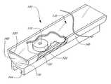
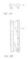
- FIG. 1shows a first embodiment of a low profile lighting device with the housing partially cut away to reveal one of the point light sources and optical diverters therein.
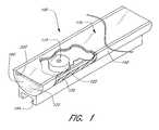
- FIG. 2is an exploded view of the embodiment illustrated in FIG. 1 .
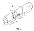
- FIG. 3shows another embodiment of a low profile lighting device.
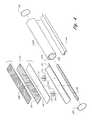
- FIG. 4is an exploded view of the embodiment illustrated in FIG. 3 .
- FIGS. 5A and 5Bare end and plan views, respectively, of a mounting channel having a slot for mounting the embodiment of FIGS. 1-2 or FIGS. 3-4 to the mounting bracket of FIGS. 6A and 6B.
- FIGS. 6A and 6Bare elevation and plan views, respectively, of a mounting bracket which is secured to a mechanical structure such as a building, and which receives the mounting channel of FIGS. 5A and 5B to mount the low profile lighting device on the building.
- FIGS. 7A and 7Bshow a collar for mechanically and electrically coupling two lighting devices.
- FIG. 7Cshows an electrical arrangement for coupling power to an end of a lighting device.
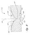
- FIG. 8shows an optical diverter which utilizes total internal reflection for laterally diverting light from a light emitting diode or other point source.
- FIGS. 9, 10 , and 11show the progression of light rays through the optical diverter of FIG. 8 .
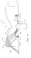
- FIG. 12shows an optical diverter which produces highly collimated “equatorial” output beam.
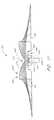
- FIG. 13shows the progression of light rays through an optical diverter having scattering centers on its top surface for diffusely transmitting some light through the top surface.
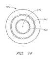
- FIG. 14shows an optical diverter having a roughened surface pattern in the form of a series concentric rings on its top surface for diffusely transmitting some light through the top surface.
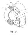
- FIG. 15shows an embodiment of a lighting device in the form of an alphanumeric character.
- a lighting device 100comprises s plural light sources, each of which includes a point source such as a light emitting diode (LED) shown in FIG. 8, and an optical diverter 110 .
- a point sourcesuch as a light emitting diode (LED) shown in FIG. 8
- an optical diverter 110Light from the LED 174 is received by the optical diverter 110 which redirects the light laterally and downwardly.
- the plural LEDsare coupled to each other electrically by a printed circuit board 130 (a wire harness is an alternative configuration).
- the point sources 174 and optical diverters 110are mounted within an elongate cavity formed by a sheet 150 of diffusively reflective material in the general form of a half or hemi cylinder.
- the sheet 150is mounted in, and extends the length of, a housing 140 , which may be an extrusion.
- the housing 140is generally elongate and has a width that is not substantially greater than the width of the light output area.
- the printed circuit board 130is disposed between the sheet 150 and the bottom of the housing 140 . Wires (not shown) pass through the sheet 150 to electrically connect the point sources to the circuit board.
- a mounting channel 144may be included on the bottom of the housing 140 for mounting the device 100 to a building.
- the mounting channel 144may, for example, be made of acrylic that is bounded or glued to the housing 140 , or the channel 144 may be integrally formed with the housing 140 as part of an extrusion process.
- the light that exits the diverters 110is reflected by the diffusely reflecting sheet 150 , located between the optical diverters 110 and the circuit board 130 , as well as by diffusely reflecting end caps 160 connected to the housing 140 at either end of the device 100 .
- the maximum separation between adjacent optical diverters 110is preferably about twice the width of the device 100 .
- the optical diverters 110are preferably separated by at least 0.5 inches.
- surfaces of the diffusely reflecting sheet 150 and the diffusely reflecting end caps 160are preferably matte white, with diffuse reflectivity over 90%, preferably 96% or more.
- the sheet 150 and the caps 160may be coated with diffusely reflective tape, such as DRPTM Backlight Reflector (W.
- the diffusely reflecting sheet 150 and the diffusely reflecting caps 160may be constructed from a diffusely (or specularly) reflecting material, such as titanium dioxide, pigmented LexanTM polycarbonate, or SpectralonTM plastic, thereby avoiding the need to apply a separate coating to the sheet 150 and the end caps 160 .
- the reflectivity of SpectralonTM plasticis about 99%.
- the reflective surfaces 150 , 160be diffusively reflective, in an alternative embodiment these surfaces comprise specularly reflecting surfaces that are preferably faceted as in a product sold by 3M under the name Visible Mirror Film (specular or diffuse). Additionally, while the cavity of the preferred embodiment is gas-filled (with air), the cavity may also be formed by a liquid or solid.
- the sheet member 170acts as the output face of the device 100 , and comprises an optical conditioning element 210 , which may be covered with transmissive outer protective cover 200 .
- the optical conditioning element 210includes (in the direction of light propagating outward through the sheet member 170 ) one or more sheets of material, which are substantially parallel to each other, namely, a diffuser 180 , an optional first prism sheet 190 , and an optional second prism sheet 194 .
- the diffuser 180acts to randomize the direction of the light incident upon it and preferably has relatively low backscattering.
- the diffuser 180may be of any construction that will diffuse light, such as translucent sheets of plastic, or plastic with a rough surface.
- the prism sheets 190 and 194may each be a brightness-enhancing film (BEF) for reducing the solid angle of the light, with an angular emission in the range of 50 to 80 degrees full width half maximum (FWHM).
- Brightness-enhancing films suitable for use in the preferred embodimentsare commercially available from 3M Corporation.
- a thin film BEF, having linear pyramidal structures therein,is described in U.S. Pat. No. 5,684,354 to Gleckman, which is hereby incorporated by reference herein.
- the repeated structures of the sheets 190 and 194are crossed at generally 90 degrees with respect to each other, and are each oriented at 45 degrees with respect to the longitudinal axis of the elongate housing 140 .
- the diffuser 180 and the prism sheets 190 and 194 of the optical conditioning element 210spread the light uniformly over the output face of the device 100 .
- the prism sheetsalso serve to concentrate the optical energy within a field of view, and this causes the light to be directed more intensely in the direction of an observer within that field. While it is preferred that the diffuser 180 be placed below the prism sheets 190 and 194 (as shown in FIG. 2 ), it will be understood that the position of the diffuser and the prism sheets may be exchanged.
- the optical conditioning element 210 and the point source 174are preferably separated by less than 3.5 inches, more preferably by less than 2.5 inches, and still more preferably by less than 1.5 inches.
- the protective outer cover 200protects the device 100 from the environment, and may act as a color filter or contain darkened or lightened regions of a specific pattern, such as a logo, design, or alphanumeric characters.
- the point sources 174are disposed just beneath the optical diverters 110 . Electrical leads (not shown) from the point sources 174 are connected to the printed circuit board 130 , with the sheet 150 having holes punched therein for accepting the leads of the LEDs 174 , such that the sheet is positioned between the LEDs and the printed circuit board.
- the housing 140includes lips or flanges 220 for holding the diffusely reflecting sheet 150 in place.
- the sheet 150(and the LEDs 174 and the printed circuit board 130 to which the sheet 150 is attached) is advantageously flexible so that it may be slid underneath the lips 220 , permitting the sheet 150 to naturally assume a shape which is typically parabolic in cross section. When the sheet 150 assumes a parabolic cross section, light reflected off the sheet is efficiently directed towards the optical conditioner 210 .
- a device 230includes a cylindrically shaped housing 240 that functions both as a housing and a protective outer cover.
- the sheet member 170is secured to a pair of lips or flanges 244 that run along the length of the device 230 .
- the flanges 244may also function the same as the lips 220 of FIG. 2, for holding the reflecting sheet 150 in place.
- the device 230is otherwise substantially similar to its counterpart 100 of FIGS. 1-2, and similar parts are designated with the same reference numerals.
- the housing 240may be colored or include darkened portions for producing a desired visual effect. Alternatively, separate elements or layers of film (not shown) disposed between the conditioning element 170 and the housing 240 may be used for achieving a desired optical effect. Such elements may also be used in conjunction with the embodiment shown in FIGS. 1 and 2.
- the intensity of light exiting the optical conditioning element 210is spatially very uniform and thus appears to an observer to have constant luminance across the entire element 210 .
- This uniformitycan be quantified with reference to an imaginary grid of 1 mm 2 “pixels” on the output side of the optical conditioning element 210 .
- the term “pixel”means any square millimeter cell defined by an imaginary grid on the output side of the element 210 formed by two orthogonal sets of parallel lines separated by 1 mm.
- a pixel as used hereindoes not represent a discrete element, but rather corresponds to a square millimeter of the exterior surface of element 210 .
- the ratio of the luminance of adjacent pixelsis preferably between 0.95 and 1.05, more preferably between 0.98 and 1.02, and still more preferably between 0.99 and 1.01.
- the ratio of the luminance of non-adjacent pixelsis preferably between 0.5 and 2.0, more preferably between 0.57 and 1.75, still more preferably between 0.67 and 1.5, and most preferably between 0.77 and 1.3. It will be understood that a given ratio can be more or less than 1.0, depending upon whether the ratio is determined with the intensity of the more intense pixel placed in the numerator or the denominator, respectively.
- the mounting channel 144is configured to mate with a mounting bracket 250 , such as that illustrated in FIGS. 6A and 6B.
- the mounting bracket 250is attached to a plate 260 that may be fastened to a building 270 or other structure using screws 280 , bolts or the like.
- the mounting bracket 250may be made of compliant plastic (or another suitable, outdoor-rated material) and comprises a latching member 290 .
- the profile of the latching member 290is reduced by pressing the latching member 290 into the mounting channel 144 , thereby squeezing both sides of the latching member about a slot 300 , so that the latching member 290 is received by the mounting channel 144 .
- the latching member 290Once the latching member 290 is within the channel 144 , it springs back to reassume its uncompressed state (FIG. 6 A), thereby holding the lighting device 100 ( 230 ) in place.
- the lighting devices 230may be advantageously constructed in segments of various lengths, such as 2, 4, or 8 feet. Two or more segments may be coupled together by a collar 310 as illustrated in FIGS. 7A and 7B. Within the collar 310 is a dual female connector 320 for receiving respective male connectors 330 from each of two lighting devices 230 .
- the male connectors 330are electrically connected to the printed circuit board 130
- the female connector 320is tied electrically to a power source via an electrical line 340 .
- the female connector 320may be held in place within the collar 310 by, for example, rings or spokes (not shown) that extend within the collar.
- FIG. 7Cshows an alternative arrangement in which power is supplied via a single female connector 360 located at one end of one of the devices 230 . In this case, adjacent devices 230 may be connected by a dual female connector (not shown) to which no electrical line 340 is attached.
- FIG. 8shows a cross section of an optical diverter 110 a which includes a total internal reflection (TIR) region 400 with a surface 410 that is smoothly curved and defines a vortex shape forming an apex 421 that extends into the optical diverter 110 a .
- the optical diverter 110 ais surrounded by air, so that a refractive index interface is formed, which permits total internal reflection.
- the surface 410 of this embodimentsubstantially completely reflects light incident thereon, such that substantially no light is transmitted therethrough.
- the TIR region 400may advantageously have the shape of an equiangular spiral that forms a cuspate portion 420 .
- TIR diverter 8is shown as being axially and circularly symmetrical and extending 360 degrees about a vertical axis 424 aligned with and passing through the point source 174 .
- a TIR diverter(not shown) may be used in which the cuspate portion is symmetrical about a line rather than being symmetrically oriented about a point, as in FIG. 8 .
- Such a TIR diverterenjoys planar rather than radial symmetry.
- the point source 174such as an LED, is mounted below the apex 421 of the TIR surface (i.e., just below the point on the cusp 420 ) in close proximity thereto, with the reflecting surface extending 360° about the LED and apex.
- the LED 174is contained within an LED package 430 , which resides within a recess 440 in the optical diverter 110 a .
- a transparent optical coupling agentsuch as an adhesive or gel, may be used to preclude any optically interfering air gaps between the LED 174 and the optical diverter.
- the transparent optical coupling agentcould be an epoxy, silicone, or any well-known organic or inorganic optical coupling material.
- the refractive index of the coupling agentis between that of the LED package and the optical diverter 110 .
- the surface 410may be curved, or it may include a plurality of flat surfaces approximating a curve to form a totally internally reflecting (TIR) lens having a focal point.
- TIRtotally internally reflecting
- the point source 174is positioned (as shown) at this focal point, light generated by the point source 174 is totally internally reflected from the surface 410 .
- any one of a number of shapesmay be employed, such as a hyperboloid, paraboloid, cone, cusp or other surface of revolution. Mathematical modeling of these shapes can be performed with an optical analysis software package such as ASAP by Breault Research of Arlington, Arizona.
- the surface 410is contoured such that substantially all light rays emitted from the LED 174 at the focal point of surface 410 are incident on the surface 410 at an angle at least equal to the critical angle. This may be accomplished by calculating the range of possible incidence angles of light rays from the LED 174 at the focal point at various local portions of the surface 410 . The local portions are then oriented so that all rays are incident within the critical range. The local portions could be large in size so that the surface 410 consists of a collection of flat surfaces, for example. As the size of the local portion decreases, the surface 410 forms into a smoothly curved surface having, for example, the equiangular spiral shape shown in FIG. 8 .
- the surface 410need not be symmetrical.
- the surface 410is flared so that light that reflects off of the surface 410 will be directed out of and away from the optical diverter 110 a .
- the optical diverter 110 a of this embodimentacts as a lateral diverter of light.
- This flared surface 410may be viewed as extending between an apex portion of the surface 410 (corresponding to the cusp 420 of FIG. 8) and a base portion 450 above the apex.
- the base portion 450flares outwardly (radially) from the vertical axis 424 that passes through the apex 421 and the point source 174 .
- a groove 480 in the embodiment of FIG. 8(and the embodiments of FIGS. 9, 10 , 11 and 13 discussed below) has a depth such that substantially all rays which would otherwise propagate directly from the point source 174 to the side surface 120 of the diverter 110 a are intercepted by at least one wall of the groove.
- the groove 480prevents direct propagation of rays though the side surface 120 and onto the optical conditioning element 210 , and thereby prevents such rays from causing non-uniformities in the output luminance.
- FIGS. 9-11depict the optical paths of various rays within the optical diverter 110 a , in which FIG. 9 is an overview of the various paths that light rays take.
- the optical diverter 110 ais illustrated as having an annular groove 480 , one face of which (surface 490 ) is frosted.
- the groove 480redirects light from the LED 174 that is incident thereon.
- Light raysemanate from the LED 174 at the focal point of surface 410 within the LED package 430 .
- Some light rays 460are refracted through the inner side surface of the grove 480 for propagation to the top surface of the groove, where the rays 460 are again refracted for propagation to the TIR reflecting surface 410 .
- rays 470pass within the region bounded by the inner side surfaces of the groove 480 , and thus by-pass the groove for direct propagation to the TIR reflecting surface. Rays 460 and 470 both undergo TIR at surface 410 , are reflected downwards, and eventually exit the diverter through side surface 120 . As discussed above in connection with FIG. 1, light exiting the diverter 110 a is diffusely reflected by the sheet 150 and by the end caps 160 at either end of the device 100 ( 230 ), and eventually exits the device through the sheet member 170 , which faces the diffusely reflecting sheet 150 .
- FIG. 10shows light rays 460 being refracted by the walls of the groove 480 . While some rays 460 a pass directly out of the side surface 120 of the diverter 110 a after undergoing TIR, other rays 460 b are internally reflected towards the frosted surface 490 , where they are scattered in many directions before exiting the device 100 ( 230 ).
- FIG. 10also shows rays 465 , which pass through the inner side surface of the groove 480 for propagation to the frosted outer side surface 490 , where the rays 465 are scattered in many directions.
- FIG. 11shows light rays 470 undergoing TIR at surface 410 and being refracted at face 120 , whereupon the rays 470 exit the diverter 110 a .
- Surface 410can have a shape tailored to cause uniform illumination of the sheet 150 .
- an optical diverter 110 bincludes a flared reflecting surface formed by a cuspate portion 492 and a refracting portion formed by an elliptical drum lens or torus portion 494 , below the cuspate portion 492 .
- Both the cuspate portion 492 and the refracting portion 494are surfaces of revolution about an axis 496 that passes through the point source, 174 , as well as through the apex of the cuspate portion 492 .
- Light rays 498 that strike surface 410 b in the cuspate portion 492undergo total internal reflection and exit the diverter 110 b propagating nominally perpendicular to the axis 496 .
- Light rays 500 exiting a surface 502 of the toroidal portion 494are refracted so that they also propagate nominally perpendicular to the axis 496 .
- the surface 502is designed so that substantially no rays propagate from the point source 174 through the side surface 120 ′ without first undergoing TIR at surface 410 b .
- the resultant distribution of light outside of the diverter 110 bis such that the embodiment of FIG. 12 acts with an isotropic hemispheric source to produce an equatorial distribution with a latitudinal beam width depending on the relative size of the point source 174 .
- the diverter 110 bis suitable for use in the lighting devices disclosed herein, but alternatively, it may be used by itself outside of a housing 140 ( 240 ) to produce 360 degree, latitudinally narrow output in the far field.
- Typical applicationsare aircraft warning beacons for high structures and marine beacon on buoys.
- FIGS. 8-11includes a surface 410 that is totally internally reflecting with respect to light rays 460 and 470
- the embodiment of FIG. 12also includes a surface 410 b hat is totally internally reflecting
- an alternate embodimentcomprises a surface 510 which is only partially rather than totally internally reflecting.
- this embodimentincludes a flared surface comprising a cuspate portion 420 c and a base portion 450 c .
- Optical radiation 520 that would otherwise be reflected for propagation through the side face 120 of the optical diverter 110 cpasses through (i.e., is diffusely transmitted by) the surface 510 for propagation directly through the sheet member 170 , without reflecting off the reflective sheet 150 or one of the caps 160 .
- the optical diverter 110 cmay be advantageously sized to allow at least a substantial portion of the light reflected off the cavity sheet 150 to reach the optical conditioning element 210 without passing through the diverter 110 c , and the reflective surfaces 150 and 160 arranged to allow at least a substantial portion of the light transmitted through the surface 510 to reach the optical conditioning element without reflection. This feature acts to compensate for reduced illumination of the sheet 150 just beneath the diverter 110 c.
- a surface 510 that is partially reflecting and partially transmittingmay, in general, be formed by appropriately selecting the angle of incidence between the light rays 460 ( 470 ) and the surface 190 .
- the surface 510may be formed at an angle that insures that some light “leaks through” the surface 190 while other light is reflected off of surface 190 .
- the apex of the cuspated portionmay be rounded to provide controlled leakage of light from the LED 174 through the surface 510 immediately above the LED. This eliminates dark spots above the LED 174 .
- a surface 410 that is initially totally internally reflectingmay be lightly sandblasted or etched to form distributed scattering centers 530 thereon, such that some of the light incident on the scattering centers passes through the surface 410 .
- These scattering centers 530may be distributed non-uniformly on the surface 410 .
- the surface 410may be heavily etched or sandblasted to form a pattern such as a series of concentric rings 540 (see the diverter 110 d of FIG. 14) about a center 544 at an apex of the surface, which likewise results in some of the light leaking through the surface.
- the optical diverters shown in FIGS. 8-14may be comprised of material that is transparent to the light produced by the LED 174 , such as a transparent polymeric material, and may be manufactured by various well-known methods, such as machining or injection molding.
- Preferred materials for the optical diverters 110are acrylic, polycarbonate, and silicone.
- Acrylicwhich has an index of refraction of approximately 1.5, is scratch-resistant and has a lower cost relative to polycarbonate.
- polycarbonatewhich has an index of refraction of approximately 1.59, has higher temperature capabilities than acrylic.
- Polycarbonatealso has improved mechanical capabilities over acrylic.
- Siliconehas a refractive index of approximately 1.43. The refractive index of air is nearly 1.0.
- the reflectors of the preferred embodimentsare flared, another embodiment (not shown) utilizes a non-flared planar reflector which is partially reflective and partially transmissive.
- reflectionmay be provided by partially or totally reflective mirrors (not shown), in which the mirrors are preferably contoured to reflect light laterally.
- Such mirrorsmay advantageously include a curved surface, so that light is reflected over a range of angles and scattered within the device 100 ( 230 ) to provide uniform illumination of the sheet member 170 .
- This functionmay also be performed by a transparent optical element that has a non-uniform change in its index of refraction, for example, a gradient index optical element.
- the point sources 174may advantageously comprise an LED cluster that provides tricolor output, e.g., red, green, and blue, so that virtually any color may be produced by appropriately selecting the relative intensity of the respective component wavelengths. Further, both gradual and fast time-changes in color are possible, and travelling wave patterns may be generated when the respective outputs of the LEDs 174 are successively varied in a coordinated fashion.
- the point sources 174have been principally described with respect to LEDs, other point sources may be used, such as miniature incandescent filaments or arc lamps (not shown). However, LEDs are preferred because of their ability to operate at relatively low voltage (e.g., 24 volts DC or less). Also, LEDs generate no RF interference.
- a fiber optic linemay be used to distribute light to a series of optical diverters 110 , in which light is tapped off at various points along the fiber optic line (corresponding to the point sources 174 ) and is directed into the diverters.
- a laser diode or other light generatormay be used to couple light into the fiber optic line, and the fibers form the point sources of light.
- FIGS. 1-4may be used in a number of different applications, such as for decorative illumination, light boxes, backlights, and for guidance along pathways.
- the housing utilized with the optical diverters 110 and sheet member 170may be constructed in various sizes and shapes, including wide area planar, linear elongate, and curved elongate.
- FIG. 15illustrates one embodiment in which the letter “G” has been formed. Other possible embodiments will be apparent to those skilled in the art.
- the optical diverters 110may be mounted, for example, in a grid (not shown) to cover a wide-area display, the surface of which may have numbers, letters, logos, or other indicia printed thereon.
Landscapes
- Engineering & Computer Science (AREA)
- General Engineering & Computer Science (AREA)
- Physics & Mathematics (AREA)
- General Physics & Mathematics (AREA)
- Optics & Photonics (AREA)
- Non-Portable Lighting Devices Or Systems Thereof (AREA)
Abstract
Description
Claims (52)
Priority Applications (1)
| Application Number | Priority Date | Filing Date | Title |
|---|---|---|---|
| US09/620,051US6582103B1 (en) | 1996-12-12 | 2000-07-20 | Lighting apparatus |
Applications Claiming Priority (4)
| Application Number | Priority Date | Filing Date | Title |
|---|---|---|---|
| US76429896A | 1996-12-12 | 1996-12-12 | |
| US08/936,717US6473554B1 (en) | 1996-12-12 | 1997-09-24 | Lighting apparatus having low profile |
| US14492099P | 1999-07-21 | 1999-07-21 | |
| US09/620,051US6582103B1 (en) | 1996-12-12 | 2000-07-20 | Lighting apparatus |
Related Parent Applications (1)
| Application Number | Title | Priority Date | Filing Date |
|---|---|---|---|
| US08/936,717Continuation-In-PartUS6473554B1 (en) | 1996-12-12 | 1997-09-24 | Lighting apparatus having low profile |
Publications (1)
| Publication Number | Publication Date |
|---|---|
| US6582103B1true US6582103B1 (en) | 2003-06-24 |
Family
ID=27386186
Family Applications (1)
| Application Number | Title | Priority Date | Filing Date |
|---|---|---|---|
| US09/620,051Expired - LifetimeUS6582103B1 (en) | 1996-12-12 | 2000-07-20 | Lighting apparatus |
Country Status (1)
| Country | Link |
|---|---|
| US (1) | US6582103B1 (en) |
Cited By (218)
| Publication number | Priority date | Publication date | Assignee | Title |
|---|---|---|---|---|
| US20020060526A1 (en)* | 2000-02-11 | 2002-05-23 | Jos Timmermans | Light tube and power supply circuit |
| US20030011538A1 (en)* | 1997-08-26 | 2003-01-16 | Lys Ihor A. | Linear lighting apparatus and methods |
| US20030198046A1 (en)* | 2001-01-31 | 2003-10-23 | Cleaver Mark Joseph | Illumination device for simulation of neon lighting |
| US20030218878A1 (en)* | 2001-06-29 | 2003-11-27 | Permlight Products, Inc. | Modular mounting arrangement and method for light emitting diodes |
| US20040070855A1 (en)* | 2002-10-11 | 2004-04-15 | Light Prescriptions Innovators, Llc, A Delaware Limited Liability Company | Compact folded-optics illumination lens |
| US6726348B2 (en) | 2002-03-26 | 2004-04-27 | B/E Aerospace, Inc. | Illumination assembly and adjustable direction mounting |
| US20040105171A1 (en)* | 2002-12-02 | 2004-06-03 | Light Prescriptions Innovators, Llc, A Delaware Limited Liability Company | Asymmetric TIR lenses producing off-axis beams |
| US20040156199A1 (en)* | 2002-09-23 | 2004-08-12 | Nelson Rivas | LED lighting apparatus |
| US20040168359A1 (en)* | 2003-02-04 | 2004-09-02 | Cleaver Mark J. | Flexible illumination device for simulating neon lighting |
| US20040189933A1 (en)* | 2002-12-02 | 2004-09-30 | Light Prescription Innovators, Llc | Apparatus and method for use in fulfilling illumination prescription |
| US20040228131A1 (en)* | 2003-05-13 | 2004-11-18 | Light Prescriptions Innovators, Llc, A Delaware Limited Liability Company | Optical device for LED-based light-bulb substitute |
| US20040233665A1 (en)* | 2003-05-21 | 2004-11-25 | West Robert S. | Devices for creating brightness profiles |
| US20040257815A1 (en)* | 1999-10-19 | 2004-12-23 | John Popovich | Mounting arrangement for light emitting diodes |
| US20050001537A1 (en)* | 2003-03-28 | 2005-01-06 | Lumileds Lighting U.S., Llc | Multi-colored LED array with improved brightness profile and color uniformity |
| US20050024744A1 (en)* | 2003-07-29 | 2005-02-03 | Light Prescriptions Innovators, Llc | Circumferentially emitting luminaires and lens-elements formed by transverse-axis profile-sweeps |
| US20050068777A1 (en)* | 2003-09-25 | 2005-03-31 | Dragoslav Popovic | Modular LED light and method |
| US20050073495A1 (en)* | 2003-10-03 | 2005-04-07 | Gerard Harbers | LCD backlight using two-dimensional array LEDs |
| US20050077525A1 (en)* | 2003-10-09 | 2005-04-14 | Manuel Lynch | LED luminaire |
| US20050086032A1 (en)* | 2003-07-28 | 2005-04-21 | Light Prescriptions Innovators, Llc | Three-dimensional simultaneous multiple-surface method and free-form illumination-optics designed therefrom |
| US20050111241A1 (en)* | 1995-06-27 | 2005-05-26 | Parker Jeffery R. | Light emitting panel assemblies |
| US20050129358A1 (en)* | 2003-02-04 | 2005-06-16 | Light Prescriptions Innovators, Llc A Delaware Limited Liability Company | Etendue-squeezing illumination optics |
| DE102004011736A1 (en)* | 2004-03-04 | 2005-09-22 | Pintsch Bamag Antriebs- Und Verkehrstechnik Gmbh | Marker light used as a flashing police light, an obstruction light for protecting buildings, or as an airport navigation light comprises a light-emitting diode designed as a laterally emitting diode arranged at the side of an optical device |
| US20050225988A1 (en)* | 2003-05-13 | 2005-10-13 | Light Prescriptions Innovators, Llc | Optical device for LED-based lamp |
| US20050243556A1 (en)* | 2004-04-30 | 2005-11-03 | Manuel Lynch | Lighting system and method |
| US6965205B2 (en) | 1997-08-26 | 2005-11-15 | Color Kinetics Incorporated | Light emitting diode based products |
| US20050259424A1 (en)* | 2004-05-18 | 2005-11-24 | Zampini Thomas L Ii | Collimating and controlling light produced by light emitting diodes |
| US20050270775A1 (en)* | 2004-06-04 | 2005-12-08 | Lumileds Lighting U.S., Llc | Remote wavelength conversion in an illumination device |
| US7008097B1 (en) | 2003-02-25 | 2006-03-07 | Ilight Technologies, Inc. | Illumination device for simulating neon or fluorescent lighting including a waveguide and a scattering cap |
| US20060067640A1 (en)* | 2004-09-24 | 2006-03-30 | Min-Hsun Hsieh | Illumination package |
| US20060098165A1 (en)* | 2004-10-19 | 2006-05-11 | Manuel Lynch | Method and apparatus for disrupting digital photography |
| US20060109685A1 (en)* | 2004-11-24 | 2006-05-25 | Noh Ji-Whan | Side light-emitting device, backlight unit having the side light-emitting device, and liquid crystal display apparatus employing the backlight unit |
| US20060118797A1 (en)* | 2004-12-03 | 2006-06-08 | Koichi Masuyama | Light Diffusing/Collecting Member and Surface Light Source Device Using the Same |
| US7118251B1 (en) | 2003-05-23 | 2006-10-10 | Ilight Technologies, Inc. | Illumination device for simulating channel letters |
| US20060274526A1 (en)* | 2005-04-26 | 2006-12-07 | Tir Systems Ltd. | Integrated sign illumination system |
| US20060279962A1 (en)* | 2005-06-14 | 2006-12-14 | Loh Ban P | LED backlighting for displays |
| US20060285311A1 (en)* | 2005-06-19 | 2006-12-21 | Chih-Li Chang | Light-emitting device, backlight module, and liquid crystal display using the same |
| US7156537B1 (en) | 2004-05-17 | 2007-01-02 | Marie Laverne Cohrs | Strip light shade |
| US7178941B2 (en) | 2003-05-05 | 2007-02-20 | Color Kinetics Incorporated | Lighting methods and systems |
| US20070041220A1 (en)* | 2005-05-13 | 2007-02-22 | Manuel Lynch | LED-based luminaire |
| US7181876B1 (en)* | 2002-02-20 | 2007-02-27 | Ahmadi William Y | LED sign visibility enhancing device |
| US7182492B1 (en)* | 2003-12-22 | 2007-02-27 | Robert Louis Walter | License plate system having enhanced illumination |
| US20070047261A1 (en)* | 2005-08-27 | 2007-03-01 | Thompson David S | Direct-lit backlight having light recycling cavity with concave transflector |
| US20070047228A1 (en)* | 2005-08-27 | 2007-03-01 | 3M Innovative Properties Company | Methods of forming direct-lit backlights having light recycling cavity with concave transflector |
| US20070047254A1 (en)* | 2005-08-27 | 2007-03-01 | 3M Innovative Properties Company | Illumination assembly and system |
| US20070047262A1 (en)* | 2005-08-27 | 2007-03-01 | 3M Innovative Properties Company | Edge-lit backlight having light recycling cavity with concave transflector |
| US7202613B2 (en) | 2001-05-30 | 2007-04-10 | Color Kinetics Incorporated | Controlled lighting methods and apparatus |
| US20070115660A1 (en)* | 2005-11-19 | 2007-05-24 | Samsung Electronics Co., Ltd | Backlight unit and liquid crystal display comprising the same |
| US20070139798A1 (en)* | 2005-12-21 | 2007-06-21 | Epstein Kenneth A | Led emitter with radial prismatic light diverter |
| DE102006004581A1 (en)* | 2006-02-01 | 2007-08-09 | Patent-Treuhand-Gesellschaft für elektrische Glühlampen mbH | Light-module for e.g. interior lighting of aeroplane, has surface mountable semiconductor components emitting radiation, and optical device e.g. diffractive unit, that focuses radiation, which is blended by optical unit of one component |
| US20070200127A1 (en)* | 2003-05-27 | 2007-08-30 | Andrews Peter S | Power surface mount light emitting die package |
| US20070200118A1 (en)* | 2005-12-21 | 2007-08-30 | Epstein Kenneth A | Led light confinement element |
| US20070204551A1 (en)* | 2006-03-06 | 2007-09-06 | Gamasonic Ltd. | Illuminated gazebo |
| US20070258247A1 (en)* | 2006-05-02 | 2007-11-08 | Samsung Electronics Co., Ltd. | Light-emitting module capable of increasing dispersion diameter |
| US7300192B2 (en) | 2002-10-03 | 2007-11-27 | Color Kinetics Incorporated | Methods and apparatus for illuminating environments |
| US7303300B2 (en) | 2000-09-27 | 2007-12-04 | Color Kinetics Incorporated | Methods and systems for illuminating household products |
| US20070284993A1 (en)* | 2004-10-07 | 2007-12-13 | Seoul Semiconductor Co., Ltd. | Side Illumination Lens and Luminescent Device Using the Same |
| US20070290475A1 (en)* | 2006-06-19 | 2007-12-20 | Jack Reitinger | Step light |
| EP1881258A1 (en)* | 2006-07-20 | 2008-01-23 | Schefenacker Vision Systems Germany GmbH | Lamp unit with a LED with integrated light deflection body |
| FR2904682A1 (en)* | 2006-08-04 | 2008-02-08 | Thierry Marquet | Support e.g. floorboard, manufacturing method, involves introducing connection element in housing at viscous state, and hardening connection element, and sandpapering surface visible at level of orifice |
| US20080106892A1 (en)* | 2006-09-21 | 2008-05-08 | Griffiths Terence P | Light fixture |
| US20080192462A1 (en)* | 2007-02-14 | 2008-08-14 | James Steedly | Strip illumination device |
| US20080192472A1 (en)* | 2005-04-14 | 2008-08-14 | Koninklijke Philips Electronics, N.V. | Light-Emitting Device |
| EP1641052A3 (en)* | 2004-09-27 | 2008-09-17 | Enplas Corporation | Emission device, surface light source device, display and light flux control member |
| USD577852S1 (en)* | 2005-03-02 | 2008-09-30 | Nichia Corporation | Light emitting diode lens |
| EP1980785A1 (en)* | 2007-04-13 | 2008-10-15 | TRILUX GmbH & Co. KG | Lighting system |
| US20080260329A1 (en)* | 2007-04-20 | 2008-10-23 | 3M Innovative Properties Company | Lightguides having curved light injectors |
| US20080259640A1 (en)* | 1995-06-27 | 2008-10-23 | Parker Jeffery R | Light emitting panel assemblies |
| US20080260328A1 (en)* | 2007-04-20 | 2008-10-23 | 3M Innovative Properties Company | Led light extraction bar and injection optic for thin lightguide |
| CN100433385C (en)* | 2004-09-30 | 2008-11-12 | 晶元光电股份有限公司 | light emitting device |
| US20080316761A1 (en)* | 2005-07-28 | 2008-12-25 | Light Prescriptions Innovators, Llc | Free-Form Lenticular Optical Elements and Their Application to Condensers and Headlamps |
| EP2009348A2 (en) | 2007-06-29 | 2008-12-31 | Dialight Lumidrives Limited | Improved spatial luminance |
| US20090040769A1 (en)* | 2007-08-11 | 2009-02-12 | Inteled Corporation | Free-Form Lenses for Rectangular Illumination Zones |
| US7490955B1 (en)* | 2007-11-06 | 2009-02-17 | Foxsemicon Integrated Technology, Inc. | LED lamp |
| US20090067179A1 (en)* | 2003-05-13 | 2009-03-12 | Light Prescriptions Innovators, Llc | Optical device for led-based lamp |
| US20090071467A1 (en)* | 2005-07-28 | 2009-03-19 | Light Prescriptions Innovators, Llc | Multi-junction solar cells with a homogenizer system and coupled non-imaging light concentrator |
| US20090161359A1 (en)* | 2007-12-21 | 2009-06-25 | Altair Engineering, Inc. | Light distribution using a light emitting diode assembly |
| US20090167651A1 (en)* | 2005-07-28 | 2009-07-02 | Light Prescriptions Innovators, Llc | Etendue-conserving illumination-optics for backlights and frontlights |
| US20090180276A1 (en)* | 2006-07-14 | 2009-07-16 | Light Prescriptions Innovators, Llc | Brightness-enhancing film |
| US20090198157A1 (en)* | 2008-02-01 | 2009-08-06 | Eilaz Babaev | Ultrasound moxibustion method and device |
| WO2009098081A1 (en)* | 2008-02-06 | 2009-08-13 | Osram Gesellschaft mit beschränkter Haftung | Lighting module, lamp and lighting method |
| US20090303720A1 (en)* | 2005-02-28 | 2009-12-10 | Leddynamics, Inc. | LED Lighting Device |
| EP2151621A1 (en)* | 2008-08-05 | 2010-02-10 | Augux Co., Ltd. | Light emitting diode lighting set |
| US20100033946A1 (en)* | 2006-08-11 | 2010-02-11 | Light Prescriptions Innovators, Llc | Led luminance-enhancement and color-mixing by rotationally multiplexed beam-combining |
| US20100038663A1 (en)* | 2006-08-10 | 2010-02-18 | Light Prescriptions Innovators, Llc | Led light recycling for luminance enhancement and angular narrowing |
| US20100079987A1 (en)* | 2008-09-30 | 2010-04-01 | Reflexite Corporation | Tiring condensing element and methods thereof |
| US20100177532A1 (en)* | 2009-01-15 | 2010-07-15 | Altair Engineering, Inc. | Led lens |
| EP2214046A1 (en)* | 2009-02-03 | 2010-08-04 | Osram Sylvania Inc. | Beam spreading optics for light emitting diodes |
| US20100201239A1 (en)* | 2009-02-06 | 2010-08-12 | Tyco Electronics Corporation | End cap connector for a light tube |
| US20100226139A1 (en)* | 2008-12-05 | 2010-09-09 | Permlight Products, Inc. | Led-based light engine |
| US20100237254A1 (en)* | 2006-04-01 | 2010-09-23 | P.W. Circuits Limited | Fluid treatment apparatus comprising ultraviolet light emitting diode |
| US20100238669A1 (en)* | 2007-05-21 | 2010-09-23 | Illumination Management Solutions, Inc. | LED Device for Wide Beam Generation and Method of Making the Same |
| US20100301372A1 (en)* | 2003-05-27 | 2010-12-02 | Cree, Inc. | Power surface mount light emitting die package |
| US20100308346A1 (en)* | 2009-06-04 | 2010-12-09 | Silitek Electronic (Guangzhou) | Light-emitting diode and module thereof |
| US20100317212A1 (en)* | 2009-06-15 | 2010-12-16 | Tyco Electronics Corporation | End cap assembly for a light tube |
| EP2270386A1 (en)* | 2009-07-02 | 2011-01-05 | Foxsemicon Integrated Technology, Inc. | Illumination device |
| US20110063835A1 (en)* | 2002-09-23 | 2011-03-17 | Nelson Rivas | Led lighting apparatus |
| US20110069486A1 (en)* | 2009-09-18 | 2011-03-24 | Martin John D | Lighting Arrangement Using LEDs |
| US7938562B2 (en) | 2008-10-24 | 2011-05-10 | Altair Engineering, Inc. | Lighting including integral communication apparatus |
| US7946729B2 (en) | 2008-07-31 | 2011-05-24 | Altair Engineering, Inc. | Fluorescent tube replacement having longitudinally oriented LEDs |
| DE102009056385A1 (en)* | 2009-11-30 | 2011-06-01 | Osram Gesellschaft mit beschränkter Haftung | Luminaire and traffic route lighting device |
| US7954973B1 (en) | 2007-03-10 | 2011-06-07 | Stairlighting System, LLC | Stair lighting system, and method for its implementation |
| US20110141734A1 (en)* | 2009-12-11 | 2011-06-16 | Osram Sylvania Inc. | Lens generating a batwing-shaped beam distribution, and method therefor |
| US20110141729A1 (en)* | 2009-12-11 | 2011-06-16 | Osram Sylvania Inc. | Retrofit-Style Lamp and Fixture, Each Including a One-Dimensional Linear Batwing Lens |
| US20110157891A1 (en)* | 2009-11-25 | 2011-06-30 | Davis Matthew A | Systems, Methods, and Devices for Sealing LED Light Sources in a Light Module |
| US7976196B2 (en) | 2008-07-09 | 2011-07-12 | Altair Engineering, Inc. | Method of forming LED-based light and resulting LED-based light |
| US7980727B2 (en) | 2008-10-07 | 2011-07-19 | Reflexite Corporation | Monolithic tiring condensing arrays and methods thereof |
| EP2354640A1 (en)* | 2010-02-09 | 2011-08-10 | Everlight Electronics Co., Ltd. | Electronic device and lighting unit thereof |
| US20110228528A1 (en)* | 2010-03-17 | 2011-09-22 | Osram Sylvania Inc. | Retrofit-style lamp and fixture, each including a one-dimensional linear batwing lens |
| USD650113S1 (en)* | 2008-07-18 | 2011-12-06 | 3M Innovative Properties Company | Lighting device |
| US8093823B1 (en)* | 2000-02-11 | 2012-01-10 | Altair Engineering, Inc. | Light sources incorporating light emitting diodes |
| US8096671B1 (en) | 2009-04-06 | 2012-01-17 | Nmera, Llc | Light emitting diode illumination system |
| US8118447B2 (en) | 2007-12-20 | 2012-02-21 | Altair Engineering, Inc. | LED lighting apparatus with swivel connection |
| CN102374419A (en)* | 2010-08-20 | 2012-03-14 | 光宝科技股份有限公司 | Led lamp |
| JP2012079557A (en)* | 2010-10-01 | 2012-04-19 | Idec Corp | Connection member for explosion-proof device |
| US20120120644A1 (en)* | 2009-07-30 | 2012-05-17 | Osram Ag | Lighting module, lighting strip including a plurality of contiguous lighting modules, and method for preparing a lighting strip |
| US20120140462A1 (en)* | 2010-12-06 | 2012-06-07 | Cree Led Lighting Solutions, Inc. | High efficiency total internal reflection optic for solid state lighting luminaires |
| USD662653S1 (en)* | 2011-11-29 | 2012-06-26 | Full Throttle Films, Inc. | Linear lighting track mount |
| USD663068S1 (en)* | 2011-11-29 | 2012-07-03 | Full Throttle Films, Inc. | Linear lighting track |
| US8214084B2 (en) | 2008-10-24 | 2012-07-03 | Ilumisys, Inc. | Integration of LED lighting with building controls |
| US8256924B2 (en) | 2008-09-15 | 2012-09-04 | Ilumisys, Inc. | LED-based light having rapidly oscillating LEDs |
| US8299695B2 (en) | 2009-06-02 | 2012-10-30 | Ilumisys, Inc. | Screw-in LED bulb comprising a base having outwardly projecting nodes |
| US8324817B2 (en) | 2008-10-24 | 2012-12-04 | Ilumisys, Inc. | Light and light sensor |
| EP2530372A1 (en)* | 2011-05-30 | 2012-12-05 | Odelo GmbH | Light guide element for motor vehicle lights |
| US8330381B2 (en) | 2009-05-14 | 2012-12-11 | Ilumisys, Inc. | Electronic circuit for DC conversion of fluorescent lighting ballast |
| USD674965S1 (en)* | 2012-01-27 | 2013-01-22 | Hubbell Incorporated | LED optical component |
| US8360599B2 (en) | 2008-05-23 | 2013-01-29 | Ilumisys, Inc. | Electric shock resistant L.E.D. based light |
| US8362710B2 (en) | 2009-01-21 | 2013-01-29 | Ilumisys, Inc. | Direct AC-to-DC converter for passive component minimization and universal operation of LED arrays |
| US8414161B2 (en) | 2006-02-27 | 2013-04-09 | Cooper Technologies Company | LED device for wide beam generation |
| US8421366B2 (en) | 2009-06-23 | 2013-04-16 | Ilumisys, Inc. | Illumination device including LEDs and a switching power control system |
| WO2013055020A1 (en) | 2011-10-11 | 2013-04-18 | Lg Electronics Inc. | Optical assembly, backlight unit having the same, and display apparatus thereof |
| US8434912B2 (en) | 2006-02-27 | 2013-05-07 | Illumination Management Solutions, Inc. | LED device for wide beam generation |
| US8444292B2 (en) | 2008-10-24 | 2013-05-21 | Ilumisys, Inc. | End cap substitute for LED-based tube replacement light |
| US8449142B1 (en) | 2009-10-14 | 2013-05-28 | C-M Glo, Llc | Reinforced housing structure for a lighted sign or lighting fixture |
| US8454193B2 (en) | 2010-07-08 | 2013-06-04 | Ilumisys, Inc. | Independent modules for LED fluorescent light tube replacement |
| US8454205B2 (en) | 2008-08-14 | 2013-06-04 | Cooper Technologies Company | LED devices for offset wide beam generation |
| WO2013057660A3 (en)* | 2011-10-21 | 2013-06-13 | Koninklijke Philips Electronics N.V. | Light emitting arrangement |
| DE102011057097A1 (en)* | 2011-12-28 | 2013-07-04 | Richter Lighting Technologies Gmbh | Ceiling lighting arrangement |
| WO2013105046A1 (en)* | 2012-01-13 | 2013-07-18 | Koninklijke Philips N.V. | Led-based direct-view luminaire with uniform lit appearance |
| US8523394B2 (en) | 2010-10-29 | 2013-09-03 | Ilumisys, Inc. | Mechanisms for reducing risk of shock during installation of light tube |
| US8540401B2 (en) | 2010-03-26 | 2013-09-24 | Ilumisys, Inc. | LED bulb with internal heat dissipating structures |
| US8541958B2 (en) | 2010-03-26 | 2013-09-24 | Ilumisys, Inc. | LED light with thermoelectric generator |
| US8596813B2 (en) | 2010-07-12 | 2013-12-03 | Ilumisys, Inc. | Circuit board mount for LED light tube |
| US20140016299A1 (en)* | 2012-06-14 | 2014-01-16 | Solar Science, Co., Ltd. | Photon enhancement guiding structures, devices, and methods for light emitting devices |
| US8653984B2 (en) | 2008-10-24 | 2014-02-18 | Ilumisys, Inc. | Integration of LED lighting control with emergency notification systems |
| US8664880B2 (en) | 2009-01-21 | 2014-03-04 | Ilumisys, Inc. | Ballast/line detection circuit for fluorescent replacement lamps |
| WO2013179227A3 (en)* | 2012-05-29 | 2014-03-06 | Koninklijke Philips N.V. | Internal envelope infrastructure for electrical devices |
| US20140071694A1 (en)* | 2012-09-13 | 2014-03-13 | Wanjiong Lin | Lens, LED Module and Illumination System having Same |
| US8674626B2 (en) | 2008-09-02 | 2014-03-18 | Ilumisys, Inc. | LED lamp failure alerting system |
| US8727573B2 (en) | 2010-09-01 | 2014-05-20 | Cooper Technologies Company | Device and apparatus for efficient collection and re-direction of emitted radiation |
| EP2757401A1 (en)* | 2005-04-26 | 2014-07-23 | LG Innotek Co., Ltd. | Optical lens, light emitting device package using the optical lens, and backlight unit |
| US8794809B2 (en) | 2008-04-30 | 2014-08-05 | 3M Innovative Properties Company | Light injection coupler for coupling light guides |
| US20140254153A1 (en)* | 2011-10-18 | 2014-09-11 | Koninklijke Philips N.V. | Split beam luminaire and lighting system |
| US20140307449A1 (en)* | 2013-04-10 | 2014-10-16 | L&Kang, Inc | Reflection Cap for Lamp |
| US8870415B2 (en) | 2010-12-09 | 2014-10-28 | Ilumisys, Inc. | LED fluorescent tube replacement light with reduced shock hazard |
| US8901823B2 (en) | 2008-10-24 | 2014-12-02 | Ilumisys, Inc. | Light and light sensor |
| US20140355302A1 (en)* | 2013-03-15 | 2014-12-04 | Cree, Inc. | Outdoor and/or Enclosed Structure LED Luminaire for General Illumination Applications, Such as Parking Lots and Structures |
| US8979320B1 (en)* | 2013-10-23 | 2015-03-17 | Kevin McDermott | LED lighting device |
| US20150103551A1 (en)* | 2013-10-11 | 2015-04-16 | Koito Manufacturing Co., Ltd. | Vehicular headlamp |
| CN104676350A (en)* | 2013-11-27 | 2015-06-03 | 鸿富锦精密工业(深圳)有限公司 | Light emitting device and backlight module |
| US9052086B2 (en) | 2011-02-28 | 2015-06-09 | Cooper Technologies Company | Method and system for managing light from a light emitting diode |
| US9057493B2 (en) | 2010-03-26 | 2015-06-16 | Ilumisys, Inc. | LED light tube with dual sided light distribution |
| US20150167923A1 (en)* | 2012-07-30 | 2015-06-18 | Ultravision Technologies, Llc | Light Assembly for Providing Substantially Uniform Illumination |
| US9072171B2 (en) | 2011-08-24 | 2015-06-30 | Ilumisys, Inc. | Circuit board mount for LED light |
| US9080739B1 (en) | 2012-09-14 | 2015-07-14 | Cooper Technologies Company | System for producing a slender illumination pattern from a light emitting diode |
| US20150233533A1 (en)* | 2012-09-21 | 2015-08-20 | Koninklijke Philips N.V. | Led based line illumination luminaire and system |
| US9140430B2 (en) | 2011-02-28 | 2015-09-22 | Cooper Technologies Company | Method and system for managing light from a light emitting diode |
| US9163794B2 (en) | 2012-07-06 | 2015-10-20 | Ilumisys, Inc. | Power supply assembly for LED-based light tube |
| US9184518B2 (en) | 2012-03-02 | 2015-11-10 | Ilumisys, Inc. | Electrical connector header for an LED-based light |
| US9200765B1 (en) | 2012-11-20 | 2015-12-01 | Cooper Technologies Company | Method and system for redirecting light emitted from a light emitting diode |
| US9271367B2 (en) | 2012-07-09 | 2016-02-23 | Ilumisys, Inc. | System and method for controlling operation of an LED-based light |
| US9267650B2 (en) | 2013-10-09 | 2016-02-23 | Ilumisys, Inc. | Lens for an LED-based light |
| US9285531B2 (en) | 2008-08-08 | 2016-03-15 | 3M Innovative Properties Company | Lightguide having a viscoelastic layer for managing light |
| US9285084B2 (en) | 2013-03-14 | 2016-03-15 | Ilumisys, Inc. | Diffusers for LED-based lights |
| US9291320B2 (en) | 2013-01-30 | 2016-03-22 | Cree, Inc. | Consolidated troffer |
| EP2435755B1 (en)* | 2009-05-28 | 2016-03-30 | OSRAM GmbH | Lighting module and lighting device |
| US9366396B2 (en) | 2013-01-30 | 2016-06-14 | Cree, Inc. | Optical waveguide and lamp including same |
| US9366799B2 (en) | 2013-03-15 | 2016-06-14 | Cree, Inc. | Optical waveguide bodies and luminaires utilizing same |
| US9389367B2 (en) | 2013-01-30 | 2016-07-12 | Cree, Inc. | Optical waveguide and luminaire incorporating same |
| US9411086B2 (en) | 2013-01-30 | 2016-08-09 | Cree, Inc. | Optical waveguide assembly and light engine including same |
| US9442243B2 (en) | 2013-01-30 | 2016-09-13 | Cree, Inc. | Waveguide bodies including redirection features and methods of producing same |
| US9488864B2 (en) | 2014-06-28 | 2016-11-08 | Radiant Choice Limited | Light distributing optical component |
| US9510400B2 (en) | 2014-05-13 | 2016-11-29 | Ilumisys, Inc. | User input systems for an LED-based light |
| US20160353091A1 (en)* | 2014-12-15 | 2016-12-01 | Boe Technology Group Co., Ltd. | Display device and preparation method thereof |
| US9568768B2 (en) | 2014-06-28 | 2017-02-14 | Radiant Choice Limited | Wavelength mixing optical component |
| US9574717B2 (en) | 2014-01-22 | 2017-02-21 | Ilumisys, Inc. | LED-based light with addressed LEDs |
| US9625638B2 (en) | 2013-03-15 | 2017-04-18 | Cree, Inc. | Optical waveguide body |
| US9690029B2 (en) | 2013-01-30 | 2017-06-27 | Cree, Inc. | Optical waveguides and luminaires incorporating same |
| US20170211751A1 (en)* | 2014-07-23 | 2017-07-27 | Philips Lighting Holding B.V. | Lighting device, luminaire and assembly method |
| US20170261186A1 (en)* | 2016-03-08 | 2017-09-14 | Lilibrand Llc | Lighting system with lens assembly |
| US9798072B2 (en) | 2013-03-15 | 2017-10-24 | Cree, Inc. | Optical element and method of forming an optical element |
| US9869432B2 (en) | 2013-01-30 | 2018-01-16 | Cree, Inc. | Luminaires using waveguide bodies and optical elements |
| WO2018032463A1 (en)* | 2016-08-18 | 2018-02-22 | 瑞仪光电(苏州)有限公司 | Lens structure, and lamp, backlight module and display device using same |
| US9920901B2 (en) | 2013-03-15 | 2018-03-20 | Cree, Inc. | LED lensing arrangement |
| US20180306413A1 (en)* | 2016-11-16 | 2018-10-25 | Qtran, Inc. | Bendable led lighting fixture |
| US10161568B2 (en) | 2015-06-01 | 2018-12-25 | Ilumisys, Inc. | LED-based light with canted outer walls |
| US10209429B2 (en) | 2013-03-15 | 2019-02-19 | Cree, Inc. | Luminaire with selectable luminous intensity pattern |
| US10228507B2 (en) | 2008-07-10 | 2019-03-12 | 3M Innovative Properties Company | Light source and optical article including viscoelastic lightguide disposed on a substrate |
| US20190120465A1 (en)* | 2016-06-29 | 2019-04-25 | Boe Technology Group Co., Ltd. | Light source assembly, backlight module and display device |
| US10416377B2 (en) | 2016-05-06 | 2019-09-17 | Cree, Inc. | Luminaire with controllable light emission |
| US10436970B2 (en) | 2013-03-15 | 2019-10-08 | Ideal Industries Lighting Llc | Shaped optical waveguide bodies |
| US10502899B2 (en)* | 2013-03-15 | 2019-12-10 | Ideal Industries Lighting Llc | Outdoor and/or enclosed structure LED luminaire |
| US20190384225A1 (en)* | 2018-06-18 | 2019-12-19 | Tsuen Jer Enterprise Co., Ltd. | Multifunctional timepiece with led illuminating system |
| US10739513B2 (en) | 2018-08-31 | 2020-08-11 | RAB Lighting Inc. | Apparatuses and methods for efficiently directing light toward and away from a mounting surface |
| IT201900002027A1 (en)* | 2019-02-12 | 2020-08-12 | Neroluce S R L | ILLUMINATING ORGAN |
| US10801679B2 (en) | 2018-10-08 | 2020-10-13 | RAB Lighting Inc. | Apparatuses and methods for assembling luminaires |
| US10823367B1 (en)* | 2019-04-26 | 2020-11-03 | Insight Lighting, Inc. | Modular LED light fixture with spaced diffuser |
| US11028980B2 (en) | 2013-10-30 | 2021-06-08 | Ecosense Lighting Inc. | Flexible strip lighting apparatus and methods |
| US11041609B2 (en) | 2018-05-01 | 2021-06-22 | Ecosense Lighting Inc. | Lighting systems and devices with central silicone module |
| US11079628B2 (en)* | 2017-08-22 | 2021-08-03 | Enplas Corporation | Light emitting device having luminous flux control member with recess radially distant from a light incident surface |
| US11112083B2 (en) | 2013-03-15 | 2021-09-07 | Ideal Industries Lighting Llc | Optic member for an LED light fixture |
| US11296057B2 (en) | 2017-01-27 | 2022-04-05 | EcoSense Lighting, Inc. | Lighting systems with high color rendering index and uniform planar illumination |
| US11339932B2 (en) | 2017-03-09 | 2022-05-24 | Korrus, Inc. | Fixtures and lighting accessories for lighting devices |
| US11353200B2 (en) | 2018-12-17 | 2022-06-07 | Korrus, Inc. | Strip lighting system for direct input of high voltage driving power |
| US20230026950A1 (en)* | 2021-07-22 | 2023-01-26 | Nicole McKee | Portable electronics interchangeable light cover |
| US20230161127A1 (en)* | 2020-04-15 | 2023-05-25 | CommScope Connectivity Belgium BV | Device and method for sealing cables in telecommunications enclosures |
| US11719882B2 (en) | 2016-05-06 | 2023-08-08 | Ideal Industries Lighting Llc | Waveguide-based light sources with dynamic beam shaping |
| US12372219B2 (en)* | 2014-05-30 | 2025-07-29 | Cree Lighting Usa Llc | LED luminaire with a cavity, finned interior, and a curved outer wall extending from a surface on which the light source is mounted |
| US12388056B1 (en) | 2017-01-27 | 2025-08-12 | Korrus, Inc. | Linear lighting systems and processes |
Citations (64)
| Publication number | Priority date | Publication date | Assignee | Title |
|---|---|---|---|---|
| US3821590A (en) | 1971-03-29 | 1974-06-28 | Northern Electric Co | Encapsulated solid state light emitting device |
| US4045665A (en) | 1975-06-25 | 1977-08-30 | Preformed Line Products Co. | Diffuser attachment for a fluorescent lamp fixture |
| US4107767A (en) | 1976-05-10 | 1978-08-15 | Jacques Anquetin | Flexible lighting strip |
| US4267489A (en) | 1978-12-01 | 1981-05-12 | Ohno Research And Development Laboratories Company Limited | Thin schaukasten |
| US4271458A (en) | 1980-03-10 | 1981-06-02 | Tivoli Industries, Inc. | Decorative light tubing |
| US4335421A (en) | 1980-03-17 | 1982-06-15 | Modia Joseph W | Light fixture, light aperture and method of uniformly illuminating an optically diffusive viewing area |
| US4376966A (en) | 1980-04-07 | 1983-03-15 | Vista Manufacturing, Inc. | Strip lights and method of making same |
| US4418378A (en) | 1981-03-05 | 1983-11-29 | Plan Hold Corporation | Light box |
| US4471412A (en) | 1982-01-09 | 1984-09-11 | Kei Mori | Illumination device |
| US4544996A (en) | 1984-07-13 | 1985-10-01 | Tivoli Industries, Inc. | Underwater lighting system with grounded return line |
| US4628421A (en) | 1986-01-23 | 1986-12-09 | Saar Lawrence E | Strip lighting |
| US4665470A (en) | 1986-08-13 | 1987-05-12 | Tivoli Industries, Inc. | Decorative light tubing and method of manufacture thereof |
| US4791540A (en) | 1987-05-26 | 1988-12-13 | Minnesota Mining And Manufacturing Company | Light fixture providing normalized output |
| US4835661A (en) | 1986-06-16 | 1989-05-30 | Weymouth Fogelberg | Enhanced lighting unit for displayable materials |
| US4884178A (en) | 1989-03-13 | 1989-11-28 | Roberts James R | Indirect lighting fixture |
| US4908743A (en) | 1989-06-15 | 1990-03-13 | Miller Jack V | Strip lighting assembly |
| US4954931A (en) | 1988-07-08 | 1990-09-04 | Parker Hannifin Corporation | Linear diffuse light source |
| USD311588S (en) | 1988-05-23 | 1990-10-23 | Tivoli Industries, Inc. | Isle lighting assembly |
| US4989122A (en) | 1989-05-13 | 1991-01-29 | Marketing-Displays | Light box |
| US4994944A (en) | 1988-03-31 | 1991-02-19 | Consumerville Limited | Decorative lighting system |
| US4999755A (en) | 1990-06-07 | 1991-03-12 | Lin Tak Huei | Tube light |
| US5020252A (en) | 1985-05-31 | 1991-06-04 | Boef J A G De | Illuminated sign system |
| US5027262A (en) | 1988-05-24 | 1991-06-25 | Lucifier Lighting Company | Flexible light rail |
| US5034864A (en) | 1989-04-25 | 1991-07-23 | Mitsubishi Rayon Co., Ltd. | Planar light-source device and illumination apparatus using the same |
| US5034866A (en) | 1989-12-28 | 1991-07-23 | Altman Stage Lighting Co., Inc. | Multilamp strip light luminaire system |
| US5122940A (en) | 1990-01-26 | 1992-06-16 | Wiegand Gregory P | Banklight and method of uniform diffuse lighting |
| US5143433A (en) | 1991-11-01 | 1992-09-01 | Litton Systems Canada Limited | Night vision backlighting system for liquid crystal displays |
| US5186537A (en) | 1987-12-07 | 1993-02-16 | Dai-Ichi Seiko Co., Ltd. | Illumination device |
| US5195818A (en) | 1990-12-08 | 1993-03-23 | Minnesota Mining And Manufacturing Company | Elongated lamp |
| US5207495A (en) | 1991-07-08 | 1993-05-04 | Vemco Corporation | Graphic arts light box |
| US5222799A (en) | 1990-08-21 | 1993-06-29 | Diamond Stairlight Industries | Stair lights |
| US5224770A (en) | 1990-12-08 | 1993-07-06 | Minnesota Mining And Manufacturing Company | Light box |
| US5272601A (en) | 1991-09-06 | 1993-12-21 | Rockwell International Corporation | Backlighting for liquid crystal displays |
| US5309335A (en) | 1992-12-04 | 1994-05-03 | Shell Oil Company | Lighting system |
| DE4237107A1 (en) | 1992-11-03 | 1994-05-05 | Wustlich Holding Gmbh | Background illumination device for flat display surface - arranges LEDs in row parallel to one side wall on circuit board, below display surface, provides convex side wall, and fills enclosed space with light-scattering transparent material |
| US5337225A (en) | 1993-01-06 | 1994-08-09 | The Standard Products Company | Lighting strip system |
| US5373428A (en) | 1992-01-24 | 1994-12-13 | Showcard Systems Retail Limited | Lightbox for display purposes |
| US5381309A (en) | 1993-09-30 | 1995-01-10 | Honeywell Inc. | Backlit display with enhanced viewing properties |
| US5386357A (en) | 1992-12-04 | 1995-01-31 | Shell Oil Company | Light box |
| US5430627A (en) | 1993-06-16 | 1995-07-04 | Tivoli Lighting, Inc. | Step lighting apparatus |
| US5438495A (en) | 1989-06-16 | 1995-08-01 | Airport Technology In Scandinavia Ab | Embedded light fitting for runways |
| US5493481A (en) | 1990-01-26 | 1996-02-20 | Wiegand; Gregory P. | Banklight and method of gradated diffuse lighting |
| US5504545A (en) | 1993-10-29 | 1996-04-02 | West Electric Company, Ltd. | Illuminating apparatus |
| US5523930A (en) | 1990-08-24 | 1996-06-04 | Fritts; Robert W. | Fluorescent backlit displays or the like |
| US5537302A (en) | 1992-12-23 | 1996-07-16 | Marketing Displays, Inc. | Illuminated sign with patterned openings on light dispersion member |
| EP0732679A1 (en) | 1995-03-16 | 1996-09-18 | Hayashi Telempu Co., Ltd. | Display panel for instruments installed in vehicles |
| EP0733850A2 (en) | 1995-02-24 | 1996-09-25 | Bartenbach, Christian | Luminary |
| US5570525A (en) | 1995-01-06 | 1996-11-05 | Signstrut, Ltd. | Flexible face sign with uniform luminosity |
| US5575459A (en) | 1995-04-27 | 1996-11-19 | Uniglo Canada Inc. | Light emitting diode lamp |
| US5669700A (en) | 1996-02-16 | 1997-09-23 | Exhibit-Group/Giltspur, Inc. | Light intensity equalizing element for lighted display panel |
| US5685633A (en) | 1994-12-08 | 1997-11-11 | Engel; Hartmut S. | Lamp for elongate lighting means |
| US5688042A (en) | 1995-11-17 | 1997-11-18 | Lumacell, Inc. | LED lamp |
| US5726706A (en) | 1995-06-19 | 1998-03-10 | Tivoli Industries, Inc. | Tubular lighting security system |
| US5746503A (en) | 1992-12-23 | 1998-05-05 | Marketing Displays Inc. | Illuminated canopy system |
| WO1998026212A1 (en) | 1996-12-12 | 1998-06-18 | Teledyne Lighting And Display Products, Inc. | Lighting apparatus having low profile |
| US5826973A (en) | 1995-09-14 | 1998-10-27 | Melzian; John M. | Illuminated display with uniform luminance |
| US5848837A (en) | 1995-08-28 | 1998-12-15 | Stantech | Integrally formed linear light strip with light emitting diodes |
| WO1999006759A1 (en) | 1997-07-28 | 1999-02-11 | Hewlett-Packard Company | Strip lighting |
| US5883684A (en) | 1997-06-19 | 1999-03-16 | Three-Five Systems, Inc. | Diffusively reflecting shield optically, coupled to backlit lightguide, containing LED's completely surrounded by the shield |
| US5897201A (en)* | 1993-01-21 | 1999-04-27 | Simon; Jerome H. | Architectural lighting distributed from contained radially collimated light |
| US5915830A (en) | 1997-12-04 | 1999-06-29 | Algonquin Industries International, Inc. | Light-tube running board lighting |
| US5918962A (en) | 1993-06-16 | 1999-07-06 | Tivoli Industries, Inc. | Dual step light and aisle indicator apparatus |
| US5934792A (en) | 1997-02-24 | 1999-08-10 | Itc, Inc. | Flexible lighting system |
| US6007225A (en) | 1997-10-16 | 1999-12-28 | Advanced Optical Technologies, L.L.C. | Directed lighting system utilizing a conical light deflector |
- 2000
- 2000-07-20USUS09/620,051patent/US6582103B1/ennot_activeExpired - Lifetime
Patent Citations (64)
| Publication number | Priority date | Publication date | Assignee | Title |
|---|---|---|---|---|
| US3821590A (en) | 1971-03-29 | 1974-06-28 | Northern Electric Co | Encapsulated solid state light emitting device |
| US4045665A (en) | 1975-06-25 | 1977-08-30 | Preformed Line Products Co. | Diffuser attachment for a fluorescent lamp fixture |
| US4107767A (en) | 1976-05-10 | 1978-08-15 | Jacques Anquetin | Flexible lighting strip |
| US4267489A (en) | 1978-12-01 | 1981-05-12 | Ohno Research And Development Laboratories Company Limited | Thin schaukasten |
| US4271458A (en) | 1980-03-10 | 1981-06-02 | Tivoli Industries, Inc. | Decorative light tubing |
| US4335421A (en) | 1980-03-17 | 1982-06-15 | Modia Joseph W | Light fixture, light aperture and method of uniformly illuminating an optically diffusive viewing area |
| US4376966A (en) | 1980-04-07 | 1983-03-15 | Vista Manufacturing, Inc. | Strip lights and method of making same |
| US4418378A (en) | 1981-03-05 | 1983-11-29 | Plan Hold Corporation | Light box |
| US4471412A (en) | 1982-01-09 | 1984-09-11 | Kei Mori | Illumination device |
| US4544996A (en) | 1984-07-13 | 1985-10-01 | Tivoli Industries, Inc. | Underwater lighting system with grounded return line |
| US5020252A (en) | 1985-05-31 | 1991-06-04 | Boef J A G De | Illuminated sign system |
| US4628421A (en) | 1986-01-23 | 1986-12-09 | Saar Lawrence E | Strip lighting |
| US4835661A (en) | 1986-06-16 | 1989-05-30 | Weymouth Fogelberg | Enhanced lighting unit for displayable materials |
| US4665470A (en) | 1986-08-13 | 1987-05-12 | Tivoli Industries, Inc. | Decorative light tubing and method of manufacture thereof |
| US4791540A (en) | 1987-05-26 | 1988-12-13 | Minnesota Mining And Manufacturing Company | Light fixture providing normalized output |
| US5186537A (en) | 1987-12-07 | 1993-02-16 | Dai-Ichi Seiko Co., Ltd. | Illumination device |
| US4994944A (en) | 1988-03-31 | 1991-02-19 | Consumerville Limited | Decorative lighting system |
| USD311588S (en) | 1988-05-23 | 1990-10-23 | Tivoli Industries, Inc. | Isle lighting assembly |
| US5027262A (en) | 1988-05-24 | 1991-06-25 | Lucifier Lighting Company | Flexible light rail |
| US4954931A (en) | 1988-07-08 | 1990-09-04 | Parker Hannifin Corporation | Linear diffuse light source |
| US4884178A (en) | 1989-03-13 | 1989-11-28 | Roberts James R | Indirect lighting fixture |
| US5034864A (en) | 1989-04-25 | 1991-07-23 | Mitsubishi Rayon Co., Ltd. | Planar light-source device and illumination apparatus using the same |
| US4989122A (en) | 1989-05-13 | 1991-01-29 | Marketing-Displays | Light box |
| US4908743A (en) | 1989-06-15 | 1990-03-13 | Miller Jack V | Strip lighting assembly |
| US5438495A (en) | 1989-06-16 | 1995-08-01 | Airport Technology In Scandinavia Ab | Embedded light fitting for runways |
| US5034866A (en) | 1989-12-28 | 1991-07-23 | Altman Stage Lighting Co., Inc. | Multilamp strip light luminaire system |
| US5122940A (en) | 1990-01-26 | 1992-06-16 | Wiegand Gregory P | Banklight and method of uniform diffuse lighting |
| US5493481A (en) | 1990-01-26 | 1996-02-20 | Wiegand; Gregory P. | Banklight and method of gradated diffuse lighting |
| US4999755A (en) | 1990-06-07 | 1991-03-12 | Lin Tak Huei | Tube light |
| US5222799A (en) | 1990-08-21 | 1993-06-29 | Diamond Stairlight Industries | Stair lights |
| US5523930A (en) | 1990-08-24 | 1996-06-04 | Fritts; Robert W. | Fluorescent backlit displays or the like |
| US5224770A (en) | 1990-12-08 | 1993-07-06 | Minnesota Mining And Manufacturing Company | Light box |
| US5195818A (en) | 1990-12-08 | 1993-03-23 | Minnesota Mining And Manufacturing Company | Elongated lamp |
| US5207495A (en) | 1991-07-08 | 1993-05-04 | Vemco Corporation | Graphic arts light box |
| US5272601A (en) | 1991-09-06 | 1993-12-21 | Rockwell International Corporation | Backlighting for liquid crystal displays |
| US5143433A (en) | 1991-11-01 | 1992-09-01 | Litton Systems Canada Limited | Night vision backlighting system for liquid crystal displays |
| US5373428A (en) | 1992-01-24 | 1994-12-13 | Showcard Systems Retail Limited | Lightbox for display purposes |
| DE4237107A1 (en) | 1992-11-03 | 1994-05-05 | Wustlich Holding Gmbh | Background illumination device for flat display surface - arranges LEDs in row parallel to one side wall on circuit board, below display surface, provides convex side wall, and fills enclosed space with light-scattering transparent material |
| US5386357A (en) | 1992-12-04 | 1995-01-31 | Shell Oil Company | Light box |
| US5309335A (en) | 1992-12-04 | 1994-05-03 | Shell Oil Company | Lighting system |
| US5537302A (en) | 1992-12-23 | 1996-07-16 | Marketing Displays, Inc. | Illuminated sign with patterned openings on light dispersion member |
| US5746503A (en) | 1992-12-23 | 1998-05-05 | Marketing Displays Inc. | Illuminated canopy system |
| US5337225A (en) | 1993-01-06 | 1994-08-09 | The Standard Products Company | Lighting strip system |
| US5897201A (en)* | 1993-01-21 | 1999-04-27 | Simon; Jerome H. | Architectural lighting distributed from contained radially collimated light |
| US5430627A (en) | 1993-06-16 | 1995-07-04 | Tivoli Lighting, Inc. | Step lighting apparatus |
| US5918962A (en) | 1993-06-16 | 1999-07-06 | Tivoli Industries, Inc. | Dual step light and aisle indicator apparatus |
| US5381309A (en) | 1993-09-30 | 1995-01-10 | Honeywell Inc. | Backlit display with enhanced viewing properties |
| US5504545A (en) | 1993-10-29 | 1996-04-02 | West Electric Company, Ltd. | Illuminating apparatus |
| US5685633A (en) | 1994-12-08 | 1997-11-11 | Engel; Hartmut S. | Lamp for elongate lighting means |
| US5570525A (en) | 1995-01-06 | 1996-11-05 | Signstrut, Ltd. | Flexible face sign with uniform luminosity |
| EP0733850A2 (en) | 1995-02-24 | 1996-09-25 | Bartenbach, Christian | Luminary |
| EP0732679A1 (en) | 1995-03-16 | 1996-09-18 | Hayashi Telempu Co., Ltd. | Display panel for instruments installed in vehicles |
| US5575459A (en) | 1995-04-27 | 1996-11-19 | Uniglo Canada Inc. | Light emitting diode lamp |
| US5726706A (en) | 1995-06-19 | 1998-03-10 | Tivoli Industries, Inc. | Tubular lighting security system |
| US5848837A (en) | 1995-08-28 | 1998-12-15 | Stantech | Integrally formed linear light strip with light emitting diodes |
| US5826973A (en) | 1995-09-14 | 1998-10-27 | Melzian; John M. | Illuminated display with uniform luminance |
| US5688042A (en) | 1995-11-17 | 1997-11-18 | Lumacell, Inc. | LED lamp |
| US5669700A (en) | 1996-02-16 | 1997-09-23 | Exhibit-Group/Giltspur, Inc. | Light intensity equalizing element for lighted display panel |
| WO1998026212A1 (en) | 1996-12-12 | 1998-06-18 | Teledyne Lighting And Display Products, Inc. | Lighting apparatus having low profile |
| US5934792A (en) | 1997-02-24 | 1999-08-10 | Itc, Inc. | Flexible lighting system |
| US5883684A (en) | 1997-06-19 | 1999-03-16 | Three-Five Systems, Inc. | Diffusively reflecting shield optically, coupled to backlit lightguide, containing LED's completely surrounded by the shield |
| WO1999006759A1 (en) | 1997-07-28 | 1999-02-11 | Hewlett-Packard Company | Strip lighting |
| US6007225A (en) | 1997-10-16 | 1999-12-28 | Advanced Optical Technologies, L.L.C. | Directed lighting system utilizing a conical light deflector |
| US5915830A (en) | 1997-12-04 | 1999-06-29 | Algonquin Industries International, Inc. | Light-tube running board lighting |
Cited By (485)
| Publication number | Priority date | Publication date | Assignee | Title |
|---|---|---|---|---|
| US7513672B2 (en) | 1995-06-27 | 2009-04-07 | Solid State Opto Limited | Light emitting panel assemblies |
| US20050213323A1 (en)* | 1995-06-27 | 2005-09-29 | Solid State Opto Limited | Light emitting panel assemblies |
| US20080266899A1 (en)* | 1995-06-27 | 2008-10-30 | Parker Jeffery R | Light emitting panel assemblies |
| US7963687B2 (en) | 1995-06-27 | 2011-06-21 | Rambus International Ltd. | Light emitting panel assemblies |
| US7178965B2 (en)* | 1995-06-27 | 2007-02-20 | Solid State Opto Limited | Light emitting panel assemblies having LEDs of multiple colors |
| US20060232965A1 (en)* | 1995-06-27 | 2006-10-19 | Solid State Opto Limited | Light emitting panel assemblies |
| US7798695B2 (en) | 1995-06-27 | 2010-09-21 | Rambus International Ltd. | Light emitting panel assemblies |
| US8123393B2 (en) | 1995-06-27 | 2012-02-28 | Rambus International Ltd. | Light emitting panel assemblies |
| US8142063B2 (en) | 1995-06-27 | 2012-03-27 | Rambus International Ltd. | Light emitting panel assemblies |
| US20050207154A1 (en)* | 1995-06-27 | 2005-09-22 | Solid State Opto Limited | Light emitting panel assemblies |
| US20100172151A1 (en)* | 1995-06-27 | 2010-07-08 | Parker Jeffery R | Light emitting panel assemblies |
| US20080259642A1 (en)* | 1995-06-27 | 2008-10-23 | Parker Jeffery R | Light emitting panel assemblies |
| US20080259640A1 (en)* | 1995-06-27 | 2008-10-23 | Parker Jeffery R | Light emitting panel assemblies |
| US20050207178A1 (en)* | 1995-06-27 | 2005-09-22 | Solid State Opto Limited | Light emitting panel assemblies |
| US8215816B2 (en) | 1995-06-27 | 2012-07-10 | Rambus International Ltd. | Light emitting panel assemblies |
| US7165873B2 (en) | 1995-06-27 | 2007-01-23 | Solid State Opto Limited | Light emitting panel assemblies |
| US7374305B2 (en) | 1995-06-27 | 2008-05-20 | Solid State Opto Limited | Light emitting panel assemblies |
| US20050213322A1 (en)* | 1995-06-27 | 2005-09-29 | Solid State Opto Limited | Light emitting panel assemblies |
| US8308334B2 (en) | 1995-06-27 | 2012-11-13 | Rambus International Ltd. | Light emitting panel assemblies |
| US7563012B2 (en) | 1995-06-27 | 2009-07-21 | Solid State Opto Limited | Light emitting panel assemblies |
| US7404660B2 (en) | 1995-06-27 | 2008-07-29 | Solid State Opto Limited | Light emitting panel assemblies |
| US7354184B2 (en) | 1995-06-27 | 2008-04-08 | Solid State Opto Limited | Light emitting panel assemblies |
| US7524101B2 (en) | 1995-06-27 | 2009-04-28 | Solid State Opto Limited | Light emitting panel assemblies |
| US20050111241A1 (en)* | 1995-06-27 | 2005-05-26 | Parker Jeffery R. | Light emitting panel assemblies |
| US7357553B2 (en) | 1995-06-27 | 2008-04-15 | Solid State Opto Limited | Light emitting panel assemblies |
| US6965205B2 (en) | 1997-08-26 | 2005-11-15 | Color Kinetics Incorporated | Light emitting diode based products |
| US20030011538A1 (en)* | 1997-08-26 | 2003-01-16 | Lys Ihor A. | Linear lighting apparatus and methods |
| US7221104B2 (en) | 1997-08-26 | 2007-05-22 | Color Kinetics Incorporated | Linear lighting apparatus and methods |
| US8186850B2 (en) | 1999-10-19 | 2012-05-29 | Permlight Products, Inc. | Mounting arrangement and method for light emitting diodes |
| US7306353B2 (en) | 1999-10-19 | 2007-12-11 | Permlight Products, Inc. | Mounting arrangement for light emitting diodes |
| US7594740B2 (en) | 1999-10-19 | 2009-09-29 | Pemlight Products, Inc. | Mounting arrangement for light emitting diodes |
| US20040257815A1 (en)* | 1999-10-19 | 2004-12-23 | John Popovich | Mounting arrangement for light emitting diodes |
| US20100087118A1 (en)* | 1999-10-19 | 2010-04-08 | Permlight Products, Inc. | Mounting arrangement and method for light emitting diodes |
| US7114831B2 (en) | 1999-10-19 | 2006-10-03 | Permlight Products, Inc. | Mounting arrangement for light emitting diodes |
| US20070030683A1 (en)* | 1999-10-19 | 2007-02-08 | John Popovich | Mounting arrangement for light emitting diodes |
| US8247985B2 (en)* | 2000-02-11 | 2012-08-21 | Ilumisys, Inc. | Light tube and power supply circuit |
| US9759392B2 (en) | 2000-02-11 | 2017-09-12 | Ilumisys, Inc. | Light tube and power supply circuit |
| US9777893B2 (en) | 2000-02-11 | 2017-10-03 | Ilumisys, Inc. | Light tube and power supply circuit |
| US9752736B2 (en) | 2000-02-11 | 2017-09-05 | Ilumisys, Inc. | Light tube and power supply circuit |
| US9746139B2 (en) | 2000-02-11 | 2017-08-29 | Ilumisys, Inc. | Light tube and power supply circuit |
| US9739428B1 (en) | 2000-02-11 | 2017-08-22 | Ilumisys, Inc. | Light tube and power supply circuit |
| US8382327B2 (en) | 2000-02-11 | 2013-02-26 | Ilumisys, Inc. | Light tube and power supply circuit |
| US7510299B2 (en) | 2000-02-11 | 2009-03-31 | Altair Engineering, Inc. | LED lighting device for replacing fluorescent tubes |
| US20050162093A1 (en)* | 2000-02-11 | 2005-07-28 | Jos Timmermans | Light tube and power supply circuit |
| US9803806B2 (en) | 2000-02-11 | 2017-10-31 | Ilumisys, Inc. | Light tube and power supply circuit |
| US20080062680A1 (en)* | 2000-02-11 | 2008-03-13 | Altair Engineering, Inc. | Lighting device with leds |
| US8482212B1 (en) | 2000-02-11 | 2013-07-09 | Ilumisys, Inc. | Light sources incorporating light emitting diodes |
| US7049761B2 (en)* | 2000-02-11 | 2006-05-23 | Altair Engineering, Inc. | Light tube and power supply circuit |
| US9416923B1 (en) | 2000-02-11 | 2016-08-16 | Ilumisys, Inc. | Light tube and power supply circuit |
| US20020060526A1 (en)* | 2000-02-11 | 2002-05-23 | Jos Timmermans | Light tube and power supply circuit |
| US9222626B1 (en) | 2000-02-11 | 2015-12-29 | Ilumisys, Inc. | Light tube and power supply circuit |
| US9006993B1 (en) | 2000-02-11 | 2015-04-14 | Ilumisys, Inc. | Light tube and power supply circuit |
| US9006990B1 (en) | 2000-02-11 | 2015-04-14 | Ilumisys, Inc. | Light tube and power supply circuit |
| US9970601B2 (en) | 2000-02-11 | 2018-05-15 | Ilumisys, Inc. | Light tube and power supply circuit |
| US8870412B1 (en) | 2000-02-11 | 2014-10-28 | Ilumisys, Inc. | Light tube and power supply circuit |
| US10054270B2 (en) | 2000-02-11 | 2018-08-21 | Ilumisys, Inc. | Light tube and power supply circuit |
| US8866396B2 (en) | 2000-02-11 | 2014-10-21 | Ilumisys, Inc. | Light tube and power supply circuit |
| US8093823B1 (en)* | 2000-02-11 | 2012-01-10 | Altair Engineering, Inc. | Light sources incorporating light emitting diodes |
| US20110156608A1 (en)* | 2000-02-11 | 2011-06-30 | Altair Engineering, Inc. | Light tube and power supply circuit |
| US10557593B2 (en) | 2000-02-11 | 2020-02-11 | Ilumisys, Inc. | Light tube and power supply circuit |
| US7303300B2 (en) | 2000-09-27 | 2007-12-04 | Color Kinetics Incorporated | Methods and systems for illuminating household products |
| US7652436B2 (en) | 2000-09-27 | 2010-01-26 | Philips Solid-State Lighting Solutions, Inc. | Methods and systems for illuminating household products |
| US20030198046A1 (en)* | 2001-01-31 | 2003-10-23 | Cleaver Mark Joseph | Illumination device for simulation of neon lighting |
| US6953262B2 (en) | 2001-01-31 | 2005-10-11 | I Light Technologies, Inc. | Illumination device for simulation of neon lighting |
| US7202613B2 (en) | 2001-05-30 | 2007-04-10 | Color Kinetics Incorporated | Controlled lighting methods and apparatus |
| US7387406B2 (en) | 2001-06-29 | 2008-06-17 | Permlight Products, Inc. | Modular mounting arrangement and method for light emitting diodes |
| US7108396B2 (en) | 2001-06-29 | 2006-09-19 | Permlight Products, Inc. | Modular mounting arrangement and method for light emitting diodes |
| US20050063183A1 (en)* | 2001-06-29 | 2005-03-24 | Jagath Swaris | Modular mounting arrangement and method for light emitting diodes |
| US6846093B2 (en) | 2001-06-29 | 2005-01-25 | Permlight Products, Inc. | Modular mounting arrangement and method for light emitting diodes |
| US20060087844A1 (en)* | 2001-06-29 | 2006-04-27 | Jagath Swaris | Modular mounting arrangement and method for light emitting diodes |
| US20030218878A1 (en)* | 2001-06-29 | 2003-11-27 | Permlight Products, Inc. | Modular mounting arrangement and method for light emitting diodes |
| US7181876B1 (en)* | 2002-02-20 | 2007-02-27 | Ahmadi William Y | LED sign visibility enhancing device |
| US6726348B2 (en) | 2002-03-26 | 2004-04-27 | B/E Aerospace, Inc. | Illumination assembly and adjustable direction mounting |
| US8530915B2 (en) | 2002-09-04 | 2013-09-10 | Cree, Inc. | Power surface mount light emitting die package |
| US20110186897A1 (en)* | 2002-09-04 | 2011-08-04 | Loh Ban P | Power surface mount light emitting die package |
| US8622582B2 (en) | 2002-09-04 | 2014-01-07 | Cree, Inc. | Power surface mount light emitting die package |
| US8710514B2 (en) | 2002-09-04 | 2014-04-29 | Cree, Inc. | Power surface mount light emitting die package |
| US8167463B2 (en) | 2002-09-04 | 2012-05-01 | Cree, Inc. | Power surface mount light emitting die package |
| US8608349B2 (en) | 2002-09-04 | 2013-12-17 | Cree, Inc. | Power surface mount light emitting die package |
| US20110121345A1 (en)* | 2002-09-04 | 2011-05-26 | Peter Scott Andrews | Power surface mount light emitting die package |
| US20070070621A1 (en)* | 2002-09-23 | 2007-03-29 | Matrix Railway Corporation | Led lighting apparatus |
| US7759876B2 (en) | 2002-09-23 | 2010-07-20 | Matrix Railway Corp. | LED lighting apparatus |
| US20110063835A1 (en)* | 2002-09-23 | 2011-03-17 | Nelson Rivas | Led lighting apparatus |
| US20040156199A1 (en)* | 2002-09-23 | 2004-08-12 | Nelson Rivas | LED lighting apparatus |
| US7114834B2 (en) | 2002-09-23 | 2006-10-03 | Matrix Railway Corporation | LED lighting apparatus |
| US7300192B2 (en) | 2002-10-03 | 2007-11-27 | Color Kinetics Incorporated | Methods and apparatus for illuminating environments |
| US6896381B2 (en) | 2002-10-11 | 2005-05-24 | Light Prescriptions Innovators, Llc | Compact folded-optics illumination lens |
| US7152985B2 (en) | 2002-10-11 | 2006-12-26 | Light Prescriptions Innovators, Llc | Compact folded-optics illumination lens |
| US7181378B2 (en) | 2002-10-11 | 2007-02-20 | Light Prescriptions Innovators, Llc | Compact folded-optics illumination lens |
| US20040246606A1 (en)* | 2002-10-11 | 2004-12-09 | Pablo Benitez | Compact folded-optics illumination lens |
| US20040070855A1 (en)* | 2002-10-11 | 2004-04-15 | Light Prescriptions Innovators, Llc, A Delaware Limited Liability Company | Compact folded-optics illumination lens |
| US20040189933A1 (en)* | 2002-12-02 | 2004-09-30 | Light Prescription Innovators, Llc | Apparatus and method for use in fulfilling illumination prescription |
| US7042655B2 (en) | 2002-12-02 | 2006-05-09 | Light Prescriptions Innovators, Llc | Apparatus and method for use in fulfilling illumination prescription |
| US20040105171A1 (en)* | 2002-12-02 | 2004-06-03 | Light Prescriptions Innovators, Llc, A Delaware Limited Liability Company | Asymmetric TIR lenses producing off-axis beams |
| US6924943B2 (en) | 2002-12-02 | 2005-08-02 | Light Prescriptions Innovators, Llc | Asymmetric TIR lenses producing off-axis beams |
| US7347599B2 (en) | 2003-02-04 | 2008-03-25 | Light Prescriptions Innovators, Llc | Etendue-squeezing illumination optics |
| US20050129358A1 (en)* | 2003-02-04 | 2005-06-16 | Light Prescriptions Innovators, Llc A Delaware Limited Liability Company | Etendue-squeezing illumination optics |
| US20040168359A1 (en)* | 2003-02-04 | 2004-09-02 | Cleaver Mark J. | Flexible illumination device for simulating neon lighting |
| US8322883B2 (en) | 2003-02-04 | 2012-12-04 | Ilight Technologies, Inc. | Flexible illumination device for simulating neon lighting |
| US7377671B2 (en) | 2003-02-04 | 2008-05-27 | Light Prescriptions Innovators, Llc | Etendue-squeezing illumination optics |
| US7008097B1 (en) | 2003-02-25 | 2006-03-07 | Ilight Technologies, Inc. | Illumination device for simulating neon or fluorescent lighting including a waveguide and a scattering cap |
| US7320531B2 (en) | 2003-03-28 | 2008-01-22 | Philips Lumileds Lighting Company, Llc | Multi-colored LED array with improved brightness profile and color uniformity |
| US20050001537A1 (en)* | 2003-03-28 | 2005-01-06 | Lumileds Lighting U.S., Llc | Multi-colored LED array with improved brightness profile and color uniformity |
| US7178941B2 (en) | 2003-05-05 | 2007-02-20 | Color Kinetics Incorporated | Lighting methods and systems |
| US8207821B2 (en) | 2003-05-05 | 2012-06-26 | Philips Solid-State Lighting Solutions, Inc. | Lighting methods and systems |
| US20080123349A1 (en)* | 2003-05-13 | 2008-05-29 | Light Prescriptions Innovators, Llc | Optical device for led-based lamp |
| US8075147B2 (en) | 2003-05-13 | 2011-12-13 | Light Prescriptions Innovators, Llc | Optical device for LED-based lamp |
| US7753561B2 (en) | 2003-05-13 | 2010-07-13 | Light Prescriptions Innovators, Llc | Optical device for LED-based lamp |
| US20090067179A1 (en)* | 2003-05-13 | 2009-03-12 | Light Prescriptions Innovators, Llc | Optical device for led-based lamp |
| US20050225988A1 (en)* | 2003-05-13 | 2005-10-13 | Light Prescriptions Innovators, Llc | Optical device for LED-based lamp |
| US20040228131A1 (en)* | 2003-05-13 | 2004-11-18 | Light Prescriptions Innovators, Llc, A Delaware Limited Liability Company | Optical device for LED-based light-bulb substitute |
| US7329029B2 (en)* | 2003-05-13 | 2008-02-12 | Light Prescriptions Innovators, Llc | Optical device for LED-based lamp |
| US7021797B2 (en) | 2003-05-13 | 2006-04-04 | Light Prescriptions Innovators, Llc | Optical device for repositioning and redistributing an LED's light |
| US6974229B2 (en) | 2003-05-21 | 2005-12-13 | Lumileds Lighting U.S., Llc | Devices for creating brightness profiles |
| US20040233665A1 (en)* | 2003-05-21 | 2004-11-25 | West Robert S. | Devices for creating brightness profiles |
| US7118251B1 (en) | 2003-05-23 | 2006-10-10 | Ilight Technologies, Inc. | Illumination device for simulating channel letters |
| US8188488B2 (en) | 2003-05-27 | 2012-05-29 | Cree, Inc. | Power surface mount light emitting die package |
| US20100301372A1 (en)* | 2003-05-27 | 2010-12-02 | Cree, Inc. | Power surface mount light emitting die package |
| US20070200127A1 (en)* | 2003-05-27 | 2007-08-30 | Andrews Peter S | Power surface mount light emitting die package |
| US7976186B2 (en) | 2003-05-27 | 2011-07-12 | Cree, Inc. | Power surface mount light emitting die package |
| US20050086032A1 (en)* | 2003-07-28 | 2005-04-21 | Light Prescriptions Innovators, Llc | Three-dimensional simultaneous multiple-surface method and free-form illumination-optics designed therefrom |
| US7460985B2 (en) | 2003-07-28 | 2008-12-02 | Light Prescriptions Innovators, Llc | Three-dimensional simultaneous multiple-surface method and free-form illumination-optics designed therefrom |
| EP1660918A4 (en)* | 2003-07-29 | 2010-05-05 | Light Prescriptions Innovators | PERIPHERAL LIGHT EMITTING LUMINAIRES AND LENS ELEMENTS FORMED BY CROSS-AXIS SCANNING PROFILES |
| EP2520953A1 (en)* | 2003-07-29 | 2012-11-07 | Light Engine Limited | Circumferentially emitting luminaires and lens elements formed by transverse-axis profile-sweeps |
| US20050024744A1 (en)* | 2003-07-29 | 2005-02-03 | Light Prescriptions Innovators, Llc | Circumferentially emitting luminaires and lens-elements formed by transverse-axis profile-sweeps |
| US7006306B2 (en) | 2003-07-29 | 2006-02-28 | Light Prescriptions Innovators, Llc | Circumferentially emitting luminaires and lens-elements formed by transverse-axis profile-sweeps |
| US20050068777A1 (en)* | 2003-09-25 | 2005-03-31 | Dragoslav Popovic | Modular LED light and method |
| US7052152B2 (en) | 2003-10-03 | 2006-05-30 | Philips Lumileds Lighting Company, Llc | LCD backlight using two-dimensional array LEDs |
| US20050073495A1 (en)* | 2003-10-03 | 2005-04-07 | Gerard Harbers | LCD backlight using two-dimensional array LEDs |
| US20050077525A1 (en)* | 2003-10-09 | 2005-04-14 | Manuel Lynch | LED luminaire |
| US7939837B2 (en) | 2003-10-09 | 2011-05-10 | Permlight Products, Inc. | LED luminaire |
| US7102172B2 (en) | 2003-10-09 | 2006-09-05 | Permlight Products, Inc. | LED luminaire |
| US20090086488A1 (en)* | 2003-10-09 | 2009-04-02 | Permlight Products, Inc. | LED luminaire |
| US20060267028A1 (en)* | 2003-10-09 | 2006-11-30 | Manuel Lynch | LED luminaire |
| US7582911B2 (en) | 2003-10-09 | 2009-09-01 | Permlight Products, Inc. | LED luminaire |
| US7182492B1 (en)* | 2003-12-22 | 2007-02-27 | Robert Louis Walter | License plate system having enhanced illumination |
| DE102004011736A1 (en)* | 2004-03-04 | 2005-09-22 | Pintsch Bamag Antriebs- Und Verkehrstechnik Gmbh | Marker light used as a flashing police light, an obstruction light for protecting buildings, or as an airport navigation light comprises a light-emitting diode designed as a laterally emitting diode arranged at the side of an optical device |
| US20050243556A1 (en)* | 2004-04-30 | 2005-11-03 | Manuel Lynch | Lighting system and method |
| EP1594172A3 (en)* | 2004-05-07 | 2012-06-13 | Philips Lumileds Lighting Company LLC | Multi-colored LED array with improved brightness profile and color uniformity |
| US7156537B1 (en) | 2004-05-17 | 2007-01-02 | Marie Laverne Cohrs | Strip light shade |
| US20050259424A1 (en)* | 2004-05-18 | 2005-11-24 | Zampini Thomas L Ii | Collimating and controlling light produced by light emitting diodes |
| US7070300B2 (en) | 2004-06-04 | 2006-07-04 | Philips Lumileds Lighting Company, Llc | Remote wavelength conversion in an illumination device |
| US20050270775A1 (en)* | 2004-06-04 | 2005-12-08 | Lumileds Lighting U.S., Llc | Remote wavelength conversion in an illumination device |
| US7341358B2 (en)* | 2004-09-24 | 2008-03-11 | Epistar Corporation | Illumination apparatus |
| US20060077685A1 (en)* | 2004-09-24 | 2006-04-13 | Min-Hsun Hsieh | Illumination apparatus |
| US8657467B2 (en) | 2004-09-24 | 2014-02-25 | Epistar Corporation | Illumination apparatus |
| US20070104963A1 (en)* | 2004-09-24 | 2007-05-10 | Min-Hsun Hsieh | Illumination package |
| US7142769B2 (en)* | 2004-09-24 | 2006-11-28 | Epistar Corporation | Illumination package |
| US7454119B2 (en)* | 2004-09-24 | 2008-11-18 | Epistar Corporation | Illumination package |
| DE102005045588B4 (en) | 2004-09-24 | 2018-05-09 | Epistar Corp. | lighting device |
| US20080112156A1 (en)* | 2004-09-24 | 2008-05-15 | Min-Hsun Hsieh | Illumination apparatus |
| US20060067640A1 (en)* | 2004-09-24 | 2006-03-30 | Min-Hsun Hsieh | Illumination package |
| EP1641052A3 (en)* | 2004-09-27 | 2008-09-17 | Enplas Corporation | Emission device, surface light source device, display and light flux control member |
| EP3285306A1 (en)* | 2004-09-27 | 2018-02-21 | Enplas Corporation | Emission device, surface light source device, display and light flux control member |
| CN100433385C (en)* | 2004-09-30 | 2008-11-12 | 晶元光电股份有限公司 | light emitting device |
| US7748873B2 (en) | 2004-10-07 | 2010-07-06 | Seoul Semiconductor Co., Ltd. | Side illumination lens and luminescent device using the same |
| US20100220485A1 (en)* | 2004-10-07 | 2010-09-02 | Seoul Semiconductor Co., Ltd. | Side illumination lens and luminescent device using the same |
| US20070284993A1 (en)* | 2004-10-07 | 2007-12-13 | Seoul Semiconductor Co., Ltd. | Side Illumination Lens and Luminescent Device Using the Same |
| US7901113B2 (en) | 2004-10-07 | 2011-03-08 | Seoul Semiconductor Co., Ltd. | Side illumination lens and luminescent device using the same |
| US20060098165A1 (en)* | 2004-10-19 | 2006-05-11 | Manuel Lynch | Method and apparatus for disrupting digital photography |
| US20060109685A1 (en)* | 2004-11-24 | 2006-05-25 | Noh Ji-Whan | Side light-emitting device, backlight unit having the side light-emitting device, and liquid crystal display apparatus employing the backlight unit |
| US7566148B2 (en)* | 2004-11-24 | 2009-07-28 | Samsung Electronics Co., Ltd. | Side light-emitting device, backlight unit having the side light-emitting device, and liquid crystal display apparatus employing the backlight unit |
| US20060118797A1 (en)* | 2004-12-03 | 2006-06-08 | Koichi Masuyama | Light Diffusing/Collecting Member and Surface Light Source Device Using the Same |
| US20090303720A1 (en)* | 2005-02-28 | 2009-12-10 | Leddynamics, Inc. | LED Lighting Device |
| USD577852S1 (en)* | 2005-03-02 | 2008-09-30 | Nichia Corporation | Light emitting diode lens |
| US20080192472A1 (en)* | 2005-04-14 | 2008-08-14 | Koninklijke Philips Electronics, N.V. | Light-Emitting Device |
| EP3133432A1 (en)* | 2005-04-26 | 2017-02-22 | LG Innotek Co., Ltd. | Optical lens, light emitting device package using the optical lens, and backlight unit |
| EP2757401A1 (en)* | 2005-04-26 | 2014-07-23 | LG Innotek Co., Ltd. | Optical lens, light emitting device package using the optical lens, and backlight unit |
| US20060274526A1 (en)* | 2005-04-26 | 2006-12-07 | Tir Systems Ltd. | Integrated sign illumination system |
| US7918591B2 (en) | 2005-05-13 | 2011-04-05 | Permlight Products, Inc. | LED-based luminaire |
| US20070041220A1 (en)* | 2005-05-13 | 2007-02-22 | Manuel Lynch | LED-based luminaire |
| US8308331B2 (en) | 2005-06-14 | 2012-11-13 | Cree, Inc. | LED backlighting for displays |
| US7980743B2 (en)* | 2005-06-14 | 2011-07-19 | Cree, Inc. | LED backlighting for displays |
| WO2006138397A3 (en)* | 2005-06-14 | 2007-03-15 | Cree Inc | Led backlighting for displays |
| US20060279962A1 (en)* | 2005-06-14 | 2006-12-14 | Loh Ban P | LED backlighting for displays |
| US20060285311A1 (en)* | 2005-06-19 | 2006-12-21 | Chih-Li Chang | Light-emitting device, backlight module, and liquid crystal display using the same |
| US8419232B2 (en) | 2005-07-28 | 2013-04-16 | Light Prescriptions Innovators, Llc | Free-form lenticular optical elements and their application to condensers and headlamps |
| US8393777B2 (en) | 2005-07-28 | 2013-03-12 | Light Prescriptions Innovators, Llc | Etendue-conserving illumination-optics for backlights and frontlights |
| US8631787B2 (en) | 2005-07-28 | 2014-01-21 | Light Prescriptions Innovators, Llc | Multi-junction solar cells with a homogenizer system and coupled non-imaging light concentrator |
| US20080316761A1 (en)* | 2005-07-28 | 2008-12-25 | Light Prescriptions Innovators, Llc | Free-Form Lenticular Optical Elements and Their Application to Condensers and Headlamps |
| US20090071467A1 (en)* | 2005-07-28 | 2009-03-19 | Light Prescriptions Innovators, Llc | Multi-junction solar cells with a homogenizer system and coupled non-imaging light concentrator |
| US20090167651A1 (en)* | 2005-07-28 | 2009-07-02 | Light Prescriptions Innovators, Llc | Etendue-conserving illumination-optics for backlights and frontlights |
| US20070047254A1 (en)* | 2005-08-27 | 2007-03-01 | 3M Innovative Properties Company | Illumination assembly and system |
| US20110025947A1 (en)* | 2005-08-27 | 2011-02-03 | 3M Innovative Properties Company | Direct-lit backlight having light recycling cavity with concave transflector |
| US20070047261A1 (en)* | 2005-08-27 | 2007-03-01 | Thompson David S | Direct-lit backlight having light recycling cavity with concave transflector |
| US7695180B2 (en) | 2005-08-27 | 2010-04-13 | 3M Innovative Properties Company | Illumination assembly and system |
| US20070047228A1 (en)* | 2005-08-27 | 2007-03-01 | 3M Innovative Properties Company | Methods of forming direct-lit backlights having light recycling cavity with concave transflector |
| US20070047262A1 (en)* | 2005-08-27 | 2007-03-01 | 3M Innovative Properties Company | Edge-lit backlight having light recycling cavity with concave transflector |
| US7815355B2 (en) | 2005-08-27 | 2010-10-19 | 3M Innovative Properties Company | Direct-lit backlight having light recycling cavity with concave transflector |
| US7537374B2 (en) | 2005-08-27 | 2009-05-26 | 3M Innovative Properties Company | Edge-lit backlight having light recycling cavity with concave transflector |
| US9857518B2 (en) | 2005-08-27 | 2018-01-02 | 3M Innovative Properties Company | Direct-lit backlight having light recycling cavity with concave transflector |
| US20070115660A1 (en)* | 2005-11-19 | 2007-05-24 | Samsung Electronics Co., Ltd | Backlight unit and liquid crystal display comprising the same |
| US20070139798A1 (en)* | 2005-12-21 | 2007-06-21 | Epstein Kenneth A | Led emitter with radial prismatic light diverter |
| US7637639B2 (en) | 2005-12-21 | 2009-12-29 | 3M Innovative Properties Company | LED emitter with radial prismatic light diverter |
| US20070200118A1 (en)* | 2005-12-21 | 2007-08-30 | Epstein Kenneth A | Led light confinement element |
| US20070211458A1 (en)* | 2006-02-01 | 2007-09-13 | Patent-Treuhand-Gesellschaft Fur Elektrische Gluhlampen Mbh | Light module, light multiple module and use of a light module or light multiple module for illumination or backlighting |
| DE102006004581A1 (en)* | 2006-02-01 | 2007-08-09 | Patent-Treuhand-Gesellschaft für elektrische Glühlampen mbH | Light-module for e.g. interior lighting of aeroplane, has surface mountable semiconductor components emitting radiation, and optical device e.g. diffractive unit, that focuses radiation, which is blended by optical unit of one component |
| US9297520B2 (en) | 2006-02-27 | 2016-03-29 | Illumination Management Solutions, Inc. | LED device for wide beam generation |
| US8511864B2 (en) | 2006-02-27 | 2013-08-20 | Illumination Management Solutions | LED device for wide beam generation |
| US8434912B2 (en) | 2006-02-27 | 2013-05-07 | Illumination Management Solutions, Inc. | LED device for wide beam generation |
| US8414161B2 (en) | 2006-02-27 | 2013-04-09 | Cooper Technologies Company | LED device for wide beam generation |
| US9388949B2 (en) | 2006-02-27 | 2016-07-12 | Illumination Management Solutions, Inc. | LED device for wide beam generation |
| US8905597B2 (en) | 2006-02-27 | 2014-12-09 | Illumination Management Solutions, Inc. | LED device for wide beam generation |
| US10174908B2 (en) | 2006-02-27 | 2019-01-08 | Eaton Intelligent Power Limited | LED device for wide beam generation |
| US20070204551A1 (en)* | 2006-03-06 | 2007-09-06 | Gamasonic Ltd. | Illuminated gazebo |
| US20100237254A1 (en)* | 2006-04-01 | 2010-09-23 | P.W. Circuits Limited | Fluid treatment apparatus comprising ultraviolet light emitting diode |
| US20070258247A1 (en)* | 2006-05-02 | 2007-11-08 | Samsung Electronics Co., Ltd. | Light-emitting module capable of increasing dispersion diameter |
| US20070290475A1 (en)* | 2006-06-19 | 2007-12-20 | Jack Reitinger | Step light |
| US20090180276A1 (en)* | 2006-07-14 | 2009-07-16 | Light Prescriptions Innovators, Llc | Brightness-enhancing film |
| US7806547B2 (en) | 2006-07-14 | 2010-10-05 | Light Prescriptions Innovators, Llc | Brightness-enhancing film |
| EP1881258A1 (en)* | 2006-07-20 | 2008-01-23 | Schefenacker Vision Systems Germany GmbH | Lamp unit with a LED with integrated light deflection body |
| FR2904682A1 (en)* | 2006-08-04 | 2008-02-08 | Thierry Marquet | Support e.g. floorboard, manufacturing method, involves introducing connection element in housing at viscous state, and hardening connection element, and sandpapering surface visible at level of orifice |
| US20100038663A1 (en)* | 2006-08-10 | 2010-02-18 | Light Prescriptions Innovators, Llc | Led light recycling for luminance enhancement and angular narrowing |
| US20100033946A1 (en)* | 2006-08-11 | 2010-02-11 | Light Prescriptions Innovators, Llc | Led luminance-enhancement and color-mixing by rotationally multiplexed beam-combining |
| US7798675B2 (en) | 2006-08-11 | 2010-09-21 | Light Prescriptions Innovators, Llc | LED luminance-enhancement and color-mixing by rotationally multiplexed beam-combining |
| US20080106892A1 (en)* | 2006-09-21 | 2008-05-08 | Griffiths Terence P | Light fixture |
| US7674010B2 (en)* | 2006-09-21 | 2010-03-09 | Hogarth Fine Art Limited | Light fixture having light emitting diode (LED) and resilient member |
| US20080192462A1 (en)* | 2007-02-14 | 2008-08-14 | James Steedly | Strip illumination device |
| US7815341B2 (en) | 2007-02-14 | 2010-10-19 | Permlight Products, Inc. | Strip illumination device |
| US7954973B1 (en) | 2007-03-10 | 2011-06-07 | Stairlighting System, LLC | Stair lighting system, and method for its implementation |
| EP1980785A1 (en)* | 2007-04-13 | 2008-10-15 | TRILUX GmbH & Co. KG | Lighting system |
| US20080260329A1 (en)* | 2007-04-20 | 2008-10-23 | 3M Innovative Properties Company | Lightguides having curved light injectors |
| US20080260328A1 (en)* | 2007-04-20 | 2008-10-23 | 3M Innovative Properties Company | Led light extraction bar and injection optic for thin lightguide |
| US9482394B2 (en) | 2007-05-21 | 2016-11-01 | Illumination Management Solutions, Inc. | LED device for wide beam generation and method of making the same |
| US8777457B2 (en) | 2007-05-21 | 2014-07-15 | Illumination Management Solutions, Inc. | LED device for wide beam generation and method of making the same |
| US8430538B2 (en) | 2007-05-21 | 2013-04-30 | Illumination Management Solutions, Inc. | LED device for wide beam generation and method of making the same |
| US20100238669A1 (en)* | 2007-05-21 | 2010-09-23 | Illumination Management Solutions, Inc. | LED Device for Wide Beam Generation and Method of Making the Same |
| US20090080198A1 (en)* | 2007-06-29 | 2009-03-26 | Dialight Lumidrives Limited | Spatial luminance |
| EP2009348A2 (en) | 2007-06-29 | 2008-12-31 | Dialight Lumidrives Limited | Improved spatial luminance |
| US8147099B2 (en) | 2007-06-29 | 2012-04-03 | Dialight Lumidrives Limited | Apparatus and method for receiving light from a point-like source and emitting light over an extended surface area |
| US20090040769A1 (en)* | 2007-08-11 | 2009-02-12 | Inteled Corporation | Free-Form Lenses for Rectangular Illumination Zones |
| US7674019B2 (en) | 2007-08-11 | 2010-03-09 | Anthony, Inc. | Free-form lenses for rectangular illumination zones |
| US7490955B1 (en)* | 2007-11-06 | 2009-02-17 | Foxsemicon Integrated Technology, Inc. | LED lamp |
| US8118447B2 (en) | 2007-12-20 | 2012-02-21 | Altair Engineering, Inc. | LED lighting apparatus with swivel connection |
| US8928025B2 (en) | 2007-12-20 | 2015-01-06 | Ilumisys, Inc. | LED lighting apparatus with swivel connection |
| US7712918B2 (en) | 2007-12-21 | 2010-05-11 | Altair Engineering , Inc. | Light distribution using a light emitting diode assembly |
| US7926975B2 (en) | 2007-12-21 | 2011-04-19 | Altair Engineering, Inc. | Light distribution using a light emitting diode assembly |
| US20090161359A1 (en)* | 2007-12-21 | 2009-06-25 | Altair Engineering, Inc. | Light distribution using a light emitting diode assembly |
| US20090198157A1 (en)* | 2008-02-01 | 2009-08-06 | Eilaz Babaev | Ultrasound moxibustion method and device |
| CN101939583A (en)* | 2008-02-06 | 2011-01-05 | 奥斯兰姆有限公司 | Lighting module, lighting device and method for lighting |
| WO2009098081A1 (en)* | 2008-02-06 | 2009-08-13 | Osram Gesellschaft mit beschränkter Haftung | Lighting module, lamp and lighting method |
| CN101939583B (en)* | 2008-02-06 | 2015-04-08 | 奥斯兰姆有限公司 | Lighting module, lighting device and lighting method |
| US20110110083A1 (en)* | 2008-02-06 | 2011-05-12 | Osram Gesellschaft Mit Beschraenkter Haftung | Lighting module, lamp and lighting method |
| US8556471B2 (en) | 2008-02-06 | 2013-10-15 | Osram Gesellschaft Mit Beschraenkter Haftung | Lighting module, lamp and lighting method |
| US8794809B2 (en) | 2008-04-30 | 2014-08-05 | 3M Innovative Properties Company | Light injection coupler for coupling light guides |
| US8360599B2 (en) | 2008-05-23 | 2013-01-29 | Ilumisys, Inc. | Electric shock resistant L.E.D. based light |
| US8807785B2 (en) | 2008-05-23 | 2014-08-19 | Ilumisys, Inc. | Electric shock resistant L.E.D. based light |
| US7976196B2 (en) | 2008-07-09 | 2011-07-12 | Altair Engineering, Inc. | Method of forming LED-based light and resulting LED-based light |
| US10228507B2 (en) | 2008-07-10 | 2019-03-12 | 3M Innovative Properties Company | Light source and optical article including viscoelastic lightguide disposed on a substrate |
| USD650114S1 (en)* | 2008-07-18 | 2011-12-06 | 3M Innovative Properties Company | Lighting device |
| USD650113S1 (en)* | 2008-07-18 | 2011-12-06 | 3M Innovative Properties Company | Lighting device |
| US7946729B2 (en) | 2008-07-31 | 2011-05-24 | Altair Engineering, Inc. | Fluorescent tube replacement having longitudinally oriented LEDs |
| EP2151621A1 (en)* | 2008-08-05 | 2010-02-10 | Augux Co., Ltd. | Light emitting diode lighting set |
| US9285531B2 (en) | 2008-08-08 | 2016-03-15 | 3M Innovative Properties Company | Lightguide having a viscoelastic layer for managing light |
| US8454205B2 (en) | 2008-08-14 | 2013-06-04 | Cooper Technologies Company | LED devices for offset wide beam generation |
| US9297517B2 (en) | 2008-08-14 | 2016-03-29 | Cooper Technologies Company | LED devices for offset wide beam generation |
| US10400996B2 (en) | 2008-08-14 | 2019-09-03 | Eaton Intelligent Power Limited | LED devices for offset wide beam generation |
| US10222030B2 (en) | 2008-08-14 | 2019-03-05 | Cooper Technologies Company | LED devices for offset wide beam generation |
| US10976027B2 (en) | 2008-08-14 | 2021-04-13 | Signify Holding B.V. | LED devices for offset wide beam generation |
| US8674626B2 (en) | 2008-09-02 | 2014-03-18 | Ilumisys, Inc. | LED lamp failure alerting system |
| US8256924B2 (en) | 2008-09-15 | 2012-09-04 | Ilumisys, Inc. | LED-based light having rapidly oscillating LEDs |
| US20100079987A1 (en)* | 2008-09-30 | 2010-04-01 | Reflexite Corporation | Tiring condensing element and methods thereof |
| US8226262B2 (en) | 2008-09-30 | 2012-07-24 | Reflexite Corporation | TIRing condensing element and methods thereof |
| US7980727B2 (en) | 2008-10-07 | 2011-07-19 | Reflexite Corporation | Monolithic tiring condensing arrays and methods thereof |
| US8214084B2 (en) | 2008-10-24 | 2012-07-03 | Ilumisys, Inc. | Integration of LED lighting with building controls |
| US8653984B2 (en) | 2008-10-24 | 2014-02-18 | Ilumisys, Inc. | Integration of LED lighting control with emergency notification systems |
| US10932339B2 (en) | 2008-10-24 | 2021-02-23 | Ilumisys, Inc. | Light and light sensor |
| US8324817B2 (en) | 2008-10-24 | 2012-12-04 | Ilumisys, Inc. | Light and light sensor |
| US9398661B2 (en) | 2008-10-24 | 2016-07-19 | Ilumisys, Inc. | Light and light sensor |
| US10036549B2 (en) | 2008-10-24 | 2018-07-31 | Ilumisys, Inc. | Lighting including integral communication apparatus |
| US11333308B2 (en) | 2008-10-24 | 2022-05-17 | Ilumisys, Inc. | Light and light sensor |
| US9353939B2 (en) | 2008-10-24 | 2016-05-31 | iLumisys, Inc | Lighting including integral communication apparatus |
| US10342086B2 (en) | 2008-10-24 | 2019-07-02 | Ilumisys, Inc. | Integration of LED lighting with building controls |
| US11073275B2 (en) | 2008-10-24 | 2021-07-27 | Ilumisys, Inc. | Lighting including integral communication apparatus |
| US8251544B2 (en) | 2008-10-24 | 2012-08-28 | Ilumisys, Inc. | Lighting including integral communication apparatus |
| US8901823B2 (en) | 2008-10-24 | 2014-12-02 | Ilumisys, Inc. | Light and light sensor |
| US10973094B2 (en) | 2008-10-24 | 2021-04-06 | Ilumisys, Inc. | Integration of LED lighting with building controls |
| US10571115B2 (en) | 2008-10-24 | 2020-02-25 | Ilumisys, Inc. | Lighting including integral communication apparatus |
| US9635727B2 (en) | 2008-10-24 | 2017-04-25 | Ilumisys, Inc. | Light and light sensor |
| US10713915B2 (en) | 2008-10-24 | 2020-07-14 | Ilumisys, Inc. | Integration of LED lighting control with emergency notification systems |
| US9101026B2 (en) | 2008-10-24 | 2015-08-04 | Ilumisys, Inc. | Integration of LED lighting with building controls |
| US9585216B2 (en) | 2008-10-24 | 2017-02-28 | Ilumisys, Inc. | Integration of LED lighting with building controls |
| US8444292B2 (en) | 2008-10-24 | 2013-05-21 | Ilumisys, Inc. | End cap substitute for LED-based tube replacement light |
| US10182480B2 (en) | 2008-10-24 | 2019-01-15 | Ilumisys, Inc. | Light and light sensor |
| US10560992B2 (en) | 2008-10-24 | 2020-02-11 | Ilumisys, Inc. | Light and light sensor |
| US8946996B2 (en) | 2008-10-24 | 2015-02-03 | Ilumisys, Inc. | Light and light sensor |
| US7938562B2 (en) | 2008-10-24 | 2011-05-10 | Altair Engineering, Inc. | Lighting including integral communication apparatus |
| US10176689B2 (en) | 2008-10-24 | 2019-01-08 | Ilumisys, Inc. | Integration of led lighting control with emergency notification systems |
| US20100226139A1 (en)* | 2008-12-05 | 2010-09-09 | Permlight Products, Inc. | Led-based light engine |
| US8926145B2 (en) | 2008-12-05 | 2015-01-06 | Permlight Products, Inc. | LED-based light engine having thermally insulated zones |
| US8556452B2 (en)* | 2009-01-15 | 2013-10-15 | Ilumisys, Inc. | LED lens |
| US20140036492A1 (en)* | 2009-01-15 | 2014-02-06 | Ilumisys, Inc. | Led lens |
| US20100177532A1 (en)* | 2009-01-15 | 2010-07-15 | Altair Engineering, Inc. | Led lens |
| US8664880B2 (en) | 2009-01-21 | 2014-03-04 | Ilumisys, Inc. | Ballast/line detection circuit for fluorescent replacement lamps |
| US8362710B2 (en) | 2009-01-21 | 2013-01-29 | Ilumisys, Inc. | Direct AC-to-DC converter for passive component minimization and universal operation of LED arrays |
| US20100195335A1 (en)* | 2009-02-03 | 2010-08-05 | Osram Sylvania, Inc. | Beam spreading optics for light emitting diodes |
| EP2214046A1 (en)* | 2009-02-03 | 2010-08-04 | Osram Sylvania Inc. | Beam spreading optics for light emitting diodes |
| US8449150B2 (en) | 2009-02-03 | 2013-05-28 | Osram Sylvania Inc. | Tir lens for light emitting diodes |
| US8232724B2 (en) | 2009-02-06 | 2012-07-31 | Tyco Electronics Corporation | End cap assembly for a light tube |
| US20100201239A1 (en)* | 2009-02-06 | 2010-08-12 | Tyco Electronics Corporation | End cap connector for a light tube |
| US8096671B1 (en) | 2009-04-06 | 2012-01-17 | Nmera, Llc | Light emitting diode illumination system |
| US8330381B2 (en) | 2009-05-14 | 2012-12-11 | Ilumisys, Inc. | Electronic circuit for DC conversion of fluorescent lighting ballast |
| US9541274B2 (en) | 2009-05-28 | 2017-01-10 | Osram Gmbh | Illumination module and illumination device comprising a flexible carrier |
| EP2435755B1 (en)* | 2009-05-28 | 2016-03-30 | OSRAM GmbH | Lighting module and lighting device |
| US8299695B2 (en) | 2009-06-02 | 2012-10-30 | Ilumisys, Inc. | Screw-in LED bulb comprising a base having outwardly projecting nodes |
| US20100308346A1 (en)* | 2009-06-04 | 2010-12-09 | Silitek Electronic (Guangzhou) | Light-emitting diode and module thereof |
| US8256930B2 (en)* | 2009-06-04 | 2012-09-04 | Silitek Electronic (Guangzhou) Co., Ltd. | Light-emitting diode module with a reflecting portion having two inclined planes opposite to each other |
| US20100317212A1 (en)* | 2009-06-15 | 2010-12-16 | Tyco Electronics Corporation | End cap assembly for a light tube |
| US8421366B2 (en) | 2009-06-23 | 2013-04-16 | Ilumisys, Inc. | Illumination device including LEDs and a switching power control system |
| US8267549B2 (en) | 2009-07-02 | 2012-09-18 | Foxsemicon Integrated Technology, Inc. | Illumination device |
| EP2270386A1 (en)* | 2009-07-02 | 2011-01-05 | Foxsemicon Integrated Technology, Inc. | Illumination device |
| US20110002125A1 (en)* | 2009-07-02 | 2011-01-06 | Foxsemicon Integrated Technology, Inc. | Illumination device |
| US9109765B2 (en)* | 2009-07-30 | 2015-08-18 | Osram Gmbh | Lighting module, lighting strip including a plurality of contiguous lighting modules, and method for preparing a lighting strip |
| US20120120644A1 (en)* | 2009-07-30 | 2012-05-17 | Osram Ag | Lighting module, lighting strip including a plurality of contiguous lighting modules, and method for preparing a lighting strip |
| US20110069486A1 (en)* | 2009-09-18 | 2011-03-24 | Martin John D | Lighting Arrangement Using LEDs |
| US8449140B2 (en) | 2009-09-18 | 2013-05-28 | C-M Glo, Llc | Lighting arrangement using LEDs |
| US8449142B1 (en) | 2009-10-14 | 2013-05-28 | C-M Glo, Llc | Reinforced housing structure for a lighted sign or lighting fixture |
| US20110157891A1 (en)* | 2009-11-25 | 2011-06-30 | Davis Matthew A | Systems, Methods, and Devices for Sealing LED Light Sources in a Light Module |
| US9052070B2 (en) | 2009-11-25 | 2015-06-09 | Cooper Technologies Company | Systems, methods, and devices for sealing LED light sources in a light module |
| US8545049B2 (en) | 2009-11-25 | 2013-10-01 | Cooper Technologies Company | Systems, methods, and devices for sealing LED light sources in a light module |
| US8840270B2 (en) | 2009-11-30 | 2014-09-23 | Osram Gmbh | Luminaire and traffic route illumination device |
| DE102009056385A1 (en)* | 2009-11-30 | 2011-06-01 | Osram Gesellschaft mit beschränkter Haftung | Luminaire and traffic route lighting device |
| US20110141729A1 (en)* | 2009-12-11 | 2011-06-16 | Osram Sylvania Inc. | Retrofit-Style Lamp and Fixture, Each Including a One-Dimensional Linear Batwing Lens |
| US8434914B2 (en) | 2009-12-11 | 2013-05-07 | Osram Sylvania Inc. | Lens generating a batwing-shaped beam distribution, and method therefor |
| US20110141734A1 (en)* | 2009-12-11 | 2011-06-16 | Osram Sylvania Inc. | Lens generating a batwing-shaped beam distribution, and method therefor |
| US9453619B2 (en) | 2009-12-11 | 2016-09-27 | Osram Sylvania Inc. | Retrofit-style lamp and fixture, each including a one-dimensional linear batwing lens |
| US9291330B2 (en) | 2009-12-11 | 2016-03-22 | Osram Sylvania Inc. | Retrofit-style lamp and fixture, each including a one-dimensional linear batwing lens |
| US8419229B2 (en) | 2010-02-09 | 2013-04-16 | Everlight Electronics Co., Ltd. | Electronic device and lighting unit thereof |
| US20110194289A1 (en)* | 2010-02-09 | 2011-08-11 | Chao-Sheng Dong | Electronic device and lighting unit thereof |
| EP2354640A1 (en)* | 2010-02-09 | 2011-08-10 | Everlight Electronics Co., Ltd. | Electronic device and lighting unit thereof |
| US20110228528A1 (en)* | 2010-03-17 | 2011-09-22 | Osram Sylvania Inc. | Retrofit-style lamp and fixture, each including a one-dimensional linear batwing lens |
| US8540401B2 (en) | 2010-03-26 | 2013-09-24 | Ilumisys, Inc. | LED bulb with internal heat dissipating structures |
| US9395075B2 (en) | 2010-03-26 | 2016-07-19 | Ilumisys, Inc. | LED bulb for incandescent bulb replacement with internal heat dissipating structures |
| US9013119B2 (en) | 2010-03-26 | 2015-04-21 | Ilumisys, Inc. | LED light with thermoelectric generator |
| US9057493B2 (en) | 2010-03-26 | 2015-06-16 | Ilumisys, Inc. | LED light tube with dual sided light distribution |
| US8840282B2 (en) | 2010-03-26 | 2014-09-23 | Ilumisys, Inc. | LED bulb with internal heat dissipating structures |
| US8541958B2 (en) | 2010-03-26 | 2013-09-24 | Ilumisys, Inc. | LED light with thermoelectric generator |
| US8454193B2 (en) | 2010-07-08 | 2013-06-04 | Ilumisys, Inc. | Independent modules for LED fluorescent light tube replacement |
| US8596813B2 (en) | 2010-07-12 | 2013-12-03 | Ilumisys, Inc. | Circuit board mount for LED light tube |
| CN102374419A (en)* | 2010-08-20 | 2012-03-14 | 光宝科技股份有限公司 | Led lamp |
| US8727573B2 (en) | 2010-09-01 | 2014-05-20 | Cooper Technologies Company | Device and apparatus for efficient collection and re-direction of emitted radiation |
| US9109781B2 (en) | 2010-09-01 | 2015-08-18 | Illumination Management Solutions, Inc. | Device and apparatus for efficient collection and re-direction of emitted radiation |
| JP2012079557A (en)* | 2010-10-01 | 2012-04-19 | Idec Corp | Connection member for explosion-proof device |
| US8894430B2 (en) | 2010-10-29 | 2014-11-25 | Ilumisys, Inc. | Mechanisms for reducing risk of shock during installation of light tube |
| US8523394B2 (en) | 2010-10-29 | 2013-09-03 | Ilumisys, Inc. | Mechanisms for reducing risk of shock during installation of light tube |
| US8556469B2 (en)* | 2010-12-06 | 2013-10-15 | Cree, Inc. | High efficiency total internal reflection optic for solid state lighting luminaires |
| US20120140462A1 (en)* | 2010-12-06 | 2012-06-07 | Cree Led Lighting Solutions, Inc. | High efficiency total internal reflection optic for solid state lighting luminaires |
| US8870415B2 (en) | 2010-12-09 | 2014-10-28 | Ilumisys, Inc. | LED fluorescent tube replacement light with reduced shock hazard |
| CN103348182B (en)* | 2011-02-09 | 2016-12-21 | 奥斯兰姆施尔凡尼亚公司 | Lens and method for generating batwing-like beam distribution |
| CN103348182A (en)* | 2011-02-09 | 2013-10-09 | 奥斯兰姆施尔凡尼亚公司 | Lens and method for generating batwing-like beam distribution |
| US9140430B2 (en) | 2011-02-28 | 2015-09-22 | Cooper Technologies Company | Method and system for managing light from a light emitting diode |
| US9574746B2 (en) | 2011-02-28 | 2017-02-21 | Cooper Technologies Company | Method and system for managing light from a light emitting diode |
| US9052086B2 (en) | 2011-02-28 | 2015-06-09 | Cooper Technologies Company | Method and system for managing light from a light emitting diode |
| US9435510B2 (en) | 2011-02-28 | 2016-09-06 | Cooper Technologies Company | Method and system for managing light from a light emitting diode |
| US9458983B2 (en) | 2011-02-28 | 2016-10-04 | Cooper Technologies Company | Method and system for managing light from a light emitting diode |
| EP2530372A1 (en)* | 2011-05-30 | 2012-12-05 | Odelo GmbH | Light guide element for motor vehicle lights |
| US9072171B2 (en) | 2011-08-24 | 2015-06-30 | Ilumisys, Inc. | Circuit board mount for LED light |
| US9222644B2 (en) | 2011-10-11 | 2015-12-29 | Lg Electronics Inc. | Optical assembly, backlight unit having the same, and display apparatus thereof |
| CN103890647B (en)* | 2011-10-11 | 2017-06-27 | Lg电子株式会社 | Optical component, backlight unit with same and display device thereof |
| WO2013055020A1 (en) | 2011-10-11 | 2013-04-18 | Lg Electronics Inc. | Optical assembly, backlight unit having the same, and display apparatus thereof |
| CN103890647A (en)* | 2011-10-11 | 2014-06-25 | Lg电子株式会社 | Optical assembly, backlight unit having the same, and display apparatus thereof |
| EP2766772A4 (en)* | 2011-10-11 | 2015-11-18 | Lg Electronics Inc | OPTICAL ASSEMBLY, RETRO-LIGHTING UNIT EQUIPPED WITH SAME, AND DISPLAY APPARATUS THEREOF |
| US20140254153A1 (en)* | 2011-10-18 | 2014-09-11 | Koninklijke Philips N.V. | Split beam luminaire and lighting system |
| US10670199B2 (en)* | 2011-10-18 | 2020-06-02 | Signify Holding B.V. | Split beam luminaire and lighting system |
| WO2013057660A3 (en)* | 2011-10-21 | 2013-06-13 | Koninklijke Philips Electronics N.V. | Light emitting arrangement |
| USD662653S1 (en)* | 2011-11-29 | 2012-06-26 | Full Throttle Films, Inc. | Linear lighting track mount |
| USD663068S1 (en)* | 2011-11-29 | 2012-07-03 | Full Throttle Films, Inc. | Linear lighting track |
| DE102011057097A1 (en)* | 2011-12-28 | 2013-07-04 | Richter Lighting Technologies Gmbh | Ceiling lighting arrangement |
| US9279547B2 (en) | 2012-01-13 | 2016-03-08 | Koninklijke Philips N.V. | LED-based direct-view luminaire with uniform lit appearance |
| WO2013105046A1 (en)* | 2012-01-13 | 2013-07-18 | Koninklijke Philips N.V. | Led-based direct-view luminaire with uniform lit appearance |
| EP3263970A1 (en)* | 2012-01-13 | 2018-01-03 | Philips Lighting Holding B.V. | Led-based direct-view luminaire with uniform lit appearance |
| USD674965S1 (en)* | 2012-01-27 | 2013-01-22 | Hubbell Incorporated | LED optical component |
| US9184518B2 (en) | 2012-03-02 | 2015-11-10 | Ilumisys, Inc. | Electrical connector header for an LED-based light |
| US9920887B2 (en) | 2012-05-29 | 2018-03-20 | Philips Lighting Holding B.V. | Internal envelope infrastructure for electrical devices |
| WO2013179227A3 (en)* | 2012-05-29 | 2014-03-06 | Koninklijke Philips N.V. | Internal envelope infrastructure for electrical devices |
| US20140016299A1 (en)* | 2012-06-14 | 2014-01-16 | Solar Science, Co., Ltd. | Photon enhancement guiding structures, devices, and methods for light emitting devices |
| US9163794B2 (en) | 2012-07-06 | 2015-10-20 | Ilumisys, Inc. | Power supply assembly for LED-based light tube |
| US9807842B2 (en) | 2012-07-09 | 2017-10-31 | Ilumisys, Inc. | System and method for controlling operation of an LED-based light |
| US10278247B2 (en) | 2012-07-09 | 2019-04-30 | Ilumisys, Inc. | System and method for controlling operation of an LED-based light |
| US10966295B2 (en) | 2012-07-09 | 2021-03-30 | Ilumisys, Inc. | System and method for controlling operation of an LED-based light |
| US9271367B2 (en) | 2012-07-09 | 2016-02-23 | Ilumisys, Inc. | System and method for controlling operation of an LED-based light |
| US10410551B2 (en) | 2012-07-30 | 2019-09-10 | Ultravision Technologies, Llc | Lighting assembly with LEDs and four-part optical elements |
| US9514663B2 (en) | 2012-07-30 | 2016-12-06 | Ultravision Technologies, Llc | Method of uniformly illuminating a billboard |
| US10460634B2 (en) | 2012-07-30 | 2019-10-29 | Ultravision Technologies, Llc | LED light assembly with transparent substrate having array of lenses for projecting light to illuminate an area |
| US9734738B2 (en) | 2012-07-30 | 2017-08-15 | Ultravision Technologies, Llc | Apparatus with lighting units |
| US9732932B2 (en) | 2012-07-30 | 2017-08-15 | Ultravision Technologies, Llc | Lighting assembly with multiple lighting units |
| US9734737B2 (en) | 2012-07-30 | 2017-08-15 | Ultravision Technologies, Llc | Outdoor billboard with lighting assemblies |
| US9685102B1 (en) | 2012-07-30 | 2017-06-20 | Ultravision Technologies, Llc | LED lighting assembly with uniform output independent of number of number of active LEDs, and method |
| US9542870B2 (en) | 2012-07-30 | 2017-01-10 | Ultravision Technologies, Llc | Billboard and lighting assembly with heat sink and three-part lens |
| US9659511B2 (en) | 2012-07-30 | 2017-05-23 | Ultravision Technologies, Llc | LED light assembly having three-part optical elements |
| US10223946B2 (en) | 2012-07-30 | 2019-03-05 | Ultravision Technologies, Llc | Lighting device with transparent substrate, heat sink and LED array for uniform illumination regardless of number of functional LEDs |
| US20150167923A1 (en)* | 2012-07-30 | 2015-06-18 | Ultravision Technologies, Llc | Light Assembly for Providing Substantially Uniform Illumination |
| US9524661B2 (en) | 2012-07-30 | 2016-12-20 | Ultravision Technologies, Llc | Outdoor billboard with lighting assemblies |
| US9589488B2 (en) | 2012-07-30 | 2017-03-07 | Ultravision Technologies, Llc | LED light assembly with three-part lens |
| US10891881B2 (en) | 2012-07-30 | 2021-01-12 | Ultravision Technologies, Llc | Lighting assembly with LEDs and optical elements |
| US9349307B1 (en) | 2012-07-30 | 2016-05-24 | Ultravision Technlologies, LLC | Forty-eight by fourteen foot outdoor billboard to be illuminated using only two lighting assemblies |
| US9812043B2 (en)* | 2012-07-30 | 2017-11-07 | Ultravision Technologies, Llc | Light assembly for providing substantially uniform illumination |
| US9947248B2 (en) | 2012-07-30 | 2018-04-17 | Ultravision Technologies, Llc | Lighting assembly with multiple lighting units |
| US10339841B2 (en) | 2012-07-30 | 2019-07-02 | Ultravision Technologies, Llc | Lighting assembly with multiple lighting units |
| US20140071694A1 (en)* | 2012-09-13 | 2014-03-13 | Wanjiong Lin | Lens, LED Module and Illumination System having Same |
| US9255669B2 (en)* | 2012-09-13 | 2016-02-09 | Wanjiong Lin | Lens, LED module and illumination system having same |
| US9080739B1 (en) | 2012-09-14 | 2015-07-14 | Cooper Technologies Company | System for producing a slender illumination pattern from a light emitting diode |
| US9470375B2 (en)* | 2012-09-21 | 2016-10-18 | Koninklijke Philips N.V. | LED based line illumination luminaire and system |
| US20150233533A1 (en)* | 2012-09-21 | 2015-08-20 | Koninklijke Philips N.V. | Led based line illumination luminaire and system |
| US9200765B1 (en) | 2012-11-20 | 2015-12-01 | Cooper Technologies Company | Method and system for redirecting light emitted from a light emitting diode |
| US9869432B2 (en) | 2013-01-30 | 2018-01-16 | Cree, Inc. | Luminaires using waveguide bodies and optical elements |
| US9389367B2 (en) | 2013-01-30 | 2016-07-12 | Cree, Inc. | Optical waveguide and luminaire incorporating same |
| US9442243B2 (en) | 2013-01-30 | 2016-09-13 | Cree, Inc. | Waveguide bodies including redirection features and methods of producing same |
| US9366396B2 (en) | 2013-01-30 | 2016-06-14 | Cree, Inc. | Optical waveguide and lamp including same |
| US9411086B2 (en) | 2013-01-30 | 2016-08-09 | Cree, Inc. | Optical waveguide assembly and light engine including same |
| US9690029B2 (en) | 2013-01-30 | 2017-06-27 | Cree, Inc. | Optical waveguides and luminaires incorporating same |
| US9291320B2 (en) | 2013-01-30 | 2016-03-22 | Cree, Inc. | Consolidated troffer |
| US9519095B2 (en) | 2013-01-30 | 2016-12-13 | Cree, Inc. | Optical waveguides |
| US9823408B2 (en) | 2013-01-30 | 2017-11-21 | Cree, Inc. | Optical waveguide and luminaire incorporating same |
| US9581751B2 (en) | 2013-01-30 | 2017-02-28 | Cree, Inc. | Optical waveguide and lamp including same |
| US10436969B2 (en) | 2013-01-30 | 2019-10-08 | Ideal Industries Lighting Llc | Optical waveguide and luminaire incorporating same |
| US11644157B2 (en) | 2013-01-30 | 2023-05-09 | Ideal Industries Lighting Llc | Luminaires using waveguide bodies and optical elements |
| US9285084B2 (en) | 2013-03-14 | 2016-03-15 | Ilumisys, Inc. | Diffusers for LED-based lights |
| US9798072B2 (en) | 2013-03-15 | 2017-10-24 | Cree, Inc. | Optical element and method of forming an optical element |
| US10209429B2 (en) | 2013-03-15 | 2019-02-19 | Cree, Inc. | Luminaire with selectable luminous intensity pattern |
| US9366799B2 (en) | 2013-03-15 | 2016-06-14 | Cree, Inc. | Optical waveguide bodies and luminaires utilizing same |
| US11112083B2 (en) | 2013-03-15 | 2021-09-07 | Ideal Industries Lighting Llc | Optic member for an LED light fixture |
| US20140355302A1 (en)* | 2013-03-15 | 2014-12-04 | Cree, Inc. | Outdoor and/or Enclosed Structure LED Luminaire for General Illumination Applications, Such as Parking Lots and Structures |
| US9625638B2 (en) | 2013-03-15 | 2017-04-18 | Cree, Inc. | Optical waveguide body |
| US10502899B2 (en)* | 2013-03-15 | 2019-12-10 | Ideal Industries Lighting Llc | Outdoor and/or enclosed structure LED luminaire |
| US10436970B2 (en) | 2013-03-15 | 2019-10-08 | Ideal Industries Lighting Llc | Shaped optical waveguide bodies |
| US9920901B2 (en) | 2013-03-15 | 2018-03-20 | Cree, Inc. | LED lensing arrangement |
| US10379278B2 (en)* | 2013-03-15 | 2019-08-13 | Ideal Industries Lighting Llc | Outdoor and/or enclosed structure LED luminaire outdoor and/or enclosed structure LED luminaire having outward illumination |
| US20140307449A1 (en)* | 2013-04-10 | 2014-10-16 | L&Kang, Inc | Reflection Cap for Lamp |
| US9267650B2 (en) | 2013-10-09 | 2016-02-23 | Ilumisys, Inc. | Lens for an LED-based light |
| US20150103551A1 (en)* | 2013-10-11 | 2015-04-16 | Koito Manufacturing Co., Ltd. | Vehicular headlamp |
| US8979320B1 (en)* | 2013-10-23 | 2015-03-17 | Kevin McDermott | LED lighting device |
| US11028980B2 (en) | 2013-10-30 | 2021-06-08 | Ecosense Lighting Inc. | Flexible strip lighting apparatus and methods |
| CN104676350A (en)* | 2013-11-27 | 2015-06-03 | 鸿富锦精密工业(深圳)有限公司 | Light emitting device and backlight module |
| CN104676350B (en)* | 2013-11-27 | 2018-05-11 | 赛恩倍吉科技顾问(深圳)有限公司 | Light emitting device and backlight module |
| US9574717B2 (en) | 2014-01-22 | 2017-02-21 | Ilumisys, Inc. | LED-based light with addressed LEDs |
| US10260686B2 (en) | 2014-01-22 | 2019-04-16 | Ilumisys, Inc. | LED-based light with addressed LEDs |
| US9510400B2 (en) | 2014-05-13 | 2016-11-29 | Ilumisys, Inc. | User input systems for an LED-based light |
| US12372219B2 (en)* | 2014-05-30 | 2025-07-29 | Cree Lighting Usa Llc | LED luminaire with a cavity, finned interior, and a curved outer wall extending from a surface on which the light source is mounted |
| US9568768B2 (en) | 2014-06-28 | 2017-02-14 | Radiant Choice Limited | Wavelength mixing optical component |
| US9488864B2 (en) | 2014-06-28 | 2016-11-08 | Radiant Choice Limited | Light distributing optical component |
| US20170211751A1 (en)* | 2014-07-23 | 2017-07-27 | Philips Lighting Holding B.V. | Lighting device, luminaire and assembly method |
| US10184616B2 (en)* | 2014-07-23 | 2019-01-22 | Philips Lighting Holding B.V. | Elongated lighting device with adhesively affixed reflector and lighting element carrier, and method of assembly |
| US20160353091A1 (en)* | 2014-12-15 | 2016-12-01 | Boe Technology Group Co., Ltd. | Display device and preparation method thereof |
| US10161568B2 (en) | 2015-06-01 | 2018-12-25 | Ilumisys, Inc. | LED-based light with canted outer walls |
| US10690296B2 (en) | 2015-06-01 | 2020-06-23 | Ilumisys, Inc. | LED-based light with canted outer walls |
| US11428370B2 (en) | 2015-06-01 | 2022-08-30 | Ilumisys, Inc. | LED-based light with canted outer walls |
| US11028972B2 (en) | 2015-06-01 | 2021-06-08 | Ilumisys, Inc. | LED-based light with canted outer walls |
| US11359796B2 (en) | 2016-03-08 | 2022-06-14 | Korrus, Inc. | Lighting system with lens assembly |
| US11060702B2 (en) | 2016-03-08 | 2021-07-13 | Ecosense Lighting Inc. | Lighting system with lens assembly |
| US10132476B2 (en)* | 2016-03-08 | 2018-11-20 | Lilibrand Llc | Lighting system with lens assembly |
| US11512838B2 (en) | 2016-03-08 | 2022-11-29 | Korrus, Inc. | Lighting system with lens assembly |
| US20170261186A1 (en)* | 2016-03-08 | 2017-09-14 | Lilibrand Llc | Lighting system with lens assembly |
| US12129990B2 (en) | 2016-03-08 | 2024-10-29 | Korrus, Inc. | Lighting system with lens assembly |
| US11867382B2 (en) | 2016-03-08 | 2024-01-09 | Korrus, Inc. | Lighting system with lens assembly |
| US11372156B2 (en) | 2016-05-06 | 2022-06-28 | Ideal Industries Lighting Llc | Waveguide-based light sources with dynamic beam shaping |
| US10527785B2 (en) | 2016-05-06 | 2020-01-07 | Ideal Industries Lighting Llc | Waveguide-based light sources with dynamic beam shaping |
| US12353005B2 (en) | 2016-05-06 | 2025-07-08 | Cree Lighting Usa Llc | Waveguide-based light sources with dynamic beam shaping |
| US11719882B2 (en) | 2016-05-06 | 2023-08-08 | Ideal Industries Lighting Llc | Waveguide-based light sources with dynamic beam shaping |
| US10416377B2 (en) | 2016-05-06 | 2019-09-17 | Cree, Inc. | Luminaire with controllable light emission |
| US10890714B2 (en) | 2016-05-06 | 2021-01-12 | Ideal Industries Lighting Llc | Waveguide-based light sources with dynamic beam shaping |
| US20190120465A1 (en)* | 2016-06-29 | 2019-04-25 | Boe Technology Group Co., Ltd. | Light source assembly, backlight module and display device |
| US10738978B2 (en)* | 2016-06-29 | 2020-08-11 | Boe Technology Group Co., Ltd. | Light source assembly, backlight module and display device |
| US10488562B2 (en) | 2016-08-18 | 2019-11-26 | Radiant Opto-Electronics (Suzhou) Co., Ltd | Lens structure and lamp, backlight module, and display device using the same |
| WO2018032463A1 (en)* | 2016-08-18 | 2018-02-22 | 瑞仪光电(苏州)有限公司 | Lens structure, and lamp, backlight module and display device using same |
| US10619828B2 (en)* | 2016-11-16 | 2020-04-14 | Qtran, Inc. | Bendable LED lighting fixture |
| US20180306413A1 (en)* | 2016-11-16 | 2018-10-25 | Qtran, Inc. | Bendable led lighting fixture |
| US11658163B2 (en) | 2017-01-27 | 2023-05-23 | Korrus, Inc. | Lighting systems with high color rendering index and uniform planar illumination |
| US12062645B2 (en) | 2017-01-27 | 2024-08-13 | Korrus, Inc. | Lighting systems with high color rendering index and uniform planar illumination |
| US12388056B1 (en) | 2017-01-27 | 2025-08-12 | Korrus, Inc. | Linear lighting systems and processes |
| US11296057B2 (en) | 2017-01-27 | 2022-04-05 | EcoSense Lighting, Inc. | Lighting systems with high color rendering index and uniform planar illumination |
| US11339932B2 (en) | 2017-03-09 | 2022-05-24 | Korrus, Inc. | Fixtures and lighting accessories for lighting devices |
| US11079628B2 (en)* | 2017-08-22 | 2021-08-03 | Enplas Corporation | Light emitting device having luminous flux control member with recess radially distant from a light incident surface |
| US11578857B2 (en) | 2018-05-01 | 2023-02-14 | Korrus, Inc. | Lighting systems and devices with central silicone module |
| US11041609B2 (en) | 2018-05-01 | 2021-06-22 | Ecosense Lighting Inc. | Lighting systems and devices with central silicone module |
| US20190384225A1 (en)* | 2018-06-18 | 2019-12-19 | Tsuen Jer Enterprise Co., Ltd. | Multifunctional timepiece with led illuminating system |
| US10739513B2 (en) | 2018-08-31 | 2020-08-11 | RAB Lighting Inc. | Apparatuses and methods for efficiently directing light toward and away from a mounting surface |
| US10801679B2 (en) | 2018-10-08 | 2020-10-13 | RAB Lighting Inc. | Apparatuses and methods for assembling luminaires |
| US11708966B2 (en) | 2018-12-17 | 2023-07-25 | Korrus, Inc. | Strip lighting system for direct input of high voltage driving power |
| US11353200B2 (en) | 2018-12-17 | 2022-06-07 | Korrus, Inc. | Strip lighting system for direct input of high voltage driving power |
| IT201900002027A1 (en)* | 2019-02-12 | 2020-08-12 | Neroluce S R L | ILLUMINATING ORGAN |
| US10823367B1 (en)* | 2019-04-26 | 2020-11-03 | Insight Lighting, Inc. | Modular LED light fixture with spaced diffuser |
| US20230161127A1 (en)* | 2020-04-15 | 2023-05-25 | CommScope Connectivity Belgium BV | Device and method for sealing cables in telecommunications enclosures |
| US11746988B2 (en)* | 2021-07-22 | 2023-09-05 | Nicole McKee | Portable electronics interchangeable light cover |
| US20230026950A1 (en)* | 2021-07-22 | 2023-01-26 | Nicole McKee | Portable electronics interchangeable light cover |
Similar Documents
| Publication | Publication Date | Title |
|---|---|---|
| US6582103B1 (en) | Lighting apparatus | |
| CA2402037C (en) | Lighting apparatus | |
| US6647199B1 (en) | Lighting apparatus having low profile | |
| KR100432045B1 (en) | Line type lighting device | |
| US7431489B2 (en) | Enhanced light fixture | |
| TW500892B (en) | Structure for achieving a linear light source geometry | |
| US5016143A (en) | Illuminating system | |
| US8430548B1 (en) | Enhanced light fixture with volumetric light scattering | |
| US6932496B2 (en) | LED-based elevated omnidirectional airfield light | |
| EP2478397B1 (en) | Light-emitting device | |
| JPH10513001A (en) | Light directing optical structure | |
| JPH077162B2 (en) | Lighting device for display device | |
| JP2004185036A (en) | Backlighting used for display | |
| JP2004534352A (en) | Backlit display | |
| EP0411065A1 (en) | Illuminating system | |
| MXPA01000646A (en) | Light with a light-guiding element. | |
| US4538216A (en) | Lighting apparatus | |
| JP2001023423A (en) | Flat light source unit | |
| US11982438B2 (en) | Uniform illumination lens and lamp thereof | |
| US20150285463A1 (en) | Lighting device for indirect illumination having prism elements | |
| JP2015057756A (en) | Luminaire | |
| JPH10144121A (en) | Luminaire | |
| JPH04142502A (en) | Face light emission lighting device | |
| IL206912A (en) | Light mixing lamp and method for making the same |
Legal Events
| Date | Code | Title | Description |
|---|---|---|---|
| AS | Assignment | Owner name:TELEDYNE LIGHTING AND DISPLAY PRODUCTS, INC., CALI Free format text:ASSIGNMENT OF ASSIGNORS INTEREST;ASSIGNORS:PELKA, DAVID G.;PARKYN, WILLIAM A.;PELKA, ERIC D.;REEL/FRAME:011639/0627 Effective date:20010320 | |
| AS | Assignment | Owner name:TELEDYNE LIGHTING AND DISPLAY PRODUCTS, INC., CALI Free format text:ASSIGNMENT OF ASSIGNORS INTEREST;ASSIGNORS:POPOVICH, JOHN M.;POPOVICH, MICHAEL J.;REEL/FRAME:012572/0705 Effective date:20020207 | |
| STCF | Information on status: patent grant | Free format text:PATENTED CASE | |
| CC | Certificate of correction | ||
| FPAY | Fee payment | Year of fee payment:4 | |
| FEPP | Fee payment procedure | Free format text:PAYOR NUMBER ASSIGNED (ORIGINAL EVENT CODE: ASPN); ENTITY STATUS OF PATENT OWNER: LARGE ENTITY | |
| AS | Assignment | Owner name:CHI MEI OPTOELECTRONICS CORP., TAIWAN Free format text:ASSIGNMENT OF ASSIGNORS INTEREST;ASSIGNOR:TELEDYNE LIGHTING & DISPLAY PRODUCTS, INC.;REEL/FRAME:020599/0337 Effective date:20080128 | |
| AS | Assignment | Owner name:CHI MEI OPTOELECTRONICS CORP., TAIWAN Free format text:ASSIGNMENT OF ASSIGNORS INTEREST;ASSIGNOR:TELEDYNE LIGHTING AND DISPLAY PRODUCTS, INC.;REEL/FRAME:020747/0661 Effective date:20080128 | |
| AS | Assignment | Owner name:CHIMEI INNOLUX CORPORATION,TAIWAN Free format text:MERGER;ASSIGNOR:CHI MEI OPTOELECTRONICS CORP.;REEL/FRAME:024369/0316 Effective date:20100318 Owner name:CHIMEI INNOLUX CORPORATION, TAIWAN Free format text:MERGER;ASSIGNOR:CHI MEI OPTOELECTRONICS CORP.;REEL/FRAME:024369/0316 Effective date:20100318 | |
| FPAY | Fee payment | Year of fee payment:8 | |
| AS | Assignment | Owner name:INNOLUX CORPORATION, TAIWAN Free format text:CHANGE OF NAME;ASSIGNOR:CHIMEI INNOLUX CORPORATION;REEL/FRAME:032604/0487 Effective date:20121219 | |
| FPAY | Fee payment | Year of fee payment:12 |