US6582095B1 - Spread illuminating apparatus - Google Patents
Spread illuminating apparatusDownload PDFInfo
- Publication number
- US6582095B1 US6582095B1US09/583,541US58354100AUS6582095B1US 6582095 B1US6582095 B1US 6582095B1US 58354100 AUS58354100 AUS 58354100AUS 6582095 B1US6582095 B1US 6582095B1
- Authority
- US
- United States
- Prior art keywords
- transparent substrate
- light
- spot
- disposed
- illuminating apparatus
- Prior art date
- Legal status (The legal status is an assumption and is not a legal conclusion. Google has not performed a legal analysis and makes no representation as to the accuracy of the status listed.)
- Expired - Lifetime, expires
Links
Images


Classifications
- G—PHYSICS
- G02—OPTICS
- G02B—OPTICAL ELEMENTS, SYSTEMS OR APPARATUS
- G02B6/00—Light guides; Structural details of arrangements comprising light guides and other optical elements, e.g. couplings
- G02B6/0001—Light guides; Structural details of arrangements comprising light guides and other optical elements, e.g. couplings specially adapted for lighting devices or systems
- G02B6/0011—Light guides; Structural details of arrangements comprising light guides and other optical elements, e.g. couplings specially adapted for lighting devices or systems the light guides being planar or of plate-like form
- G02B6/0013—Means for improving the coupling-in of light from the light source into the light guide
- G—PHYSICS
- G02—OPTICS
- G02B—OPTICAL ELEMENTS, SYSTEMS OR APPARATUS
- G02B6/00—Light guides; Structural details of arrangements comprising light guides and other optical elements, e.g. couplings
- G02B6/0001—Light guides; Structural details of arrangements comprising light guides and other optical elements, e.g. couplings specially adapted for lighting devices or systems
- G02B6/0011—Light guides; Structural details of arrangements comprising light guides and other optical elements, e.g. couplings specially adapted for lighting devices or systems the light guides being planar or of plate-like form
- G02B6/0033—Means for improving the coupling-out of light from the light guide
- G02B6/0035—Means for improving the coupling-out of light from the light guide provided on the surface of the light guide or in the bulk of it
- G02B6/0038—Linear indentations or grooves, e.g. arc-shaped grooves or meandering grooves, extending over the full length or width of the light guide
Definitions
- This inventionrelates to a spread illuminating apparatus for a display portion of a personal computer, a word processor, etc.(hereinafter referred to as “person com”).
- a cathode ray tube(so called a picture tube) has been used primarily.
- a liquid crystal panelhas been increasingly used. Therefore, a liquid crystal panel with a large number of picture elements has been developed and miniaturization of other electronic parts has been accelerated, so that a small size of personal computers such as a notebook type or the like has been rapidly becoming popular.
- a liquid crystal panelhas been heavily used for miniaturized portable information appliances and other electronic appliances. Thus the demand for the liquid crystal panels has rapidly increased.
- a cold cathode fluorescent lampCCFL
- HCFLhot cathode fluorescent lamp
- the transparent substrate 2is identical with a liquid crystal panel 1 in configuration, that is, rectangle when seen from above. On one end thereof a bar-like light conductive member 3 is disposed.
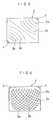
- FIG. 7shows as if the liquid crystal panel 1 and the transparent substrate 2 were apart, and the transparent substrate 2 and the light conductive member 3 were apart respectively, but actually all the parts are disposed tight to each other so that light goes through them efficiently.
- On the surface of the transparent substrate 2a number of grooves 2 a triangular in section are provided in parallel with each other as shown in FIG. 8 . Further, an optical path conversion means (as later explained) is provided on a portion of the light conductive member 3 .
- light emitting diodes 4 , 4As a light emitting body are disposed.
- this light emitting diode 4is also apart from the light conductive member 3 , but actually it is disposed tight to the light conductive member 3 .
- the color of a light emitted from the light emitting diode 4is white, and the diode is surrounded with a case or the like, when necessary, so that most of the light, when emitted with electric current supplied, is directed toward the light conductive member 3 .
- the light emitted from the light emitting diodes 4 , 4is directed through the light conductive member 3 toward the transparent substrate 2 and illuminates it. Then the light is refracted by the groove 2 a of the transparent substrate 2 toward the liquid crystal panel 1 and illuminates it.
- the image of the illuminated liquid crystal panel 1is viewed by a viewer through the transparent substrate 2 .
- the light conductive member 3is, as explained, provided with an optical path conversion means.
- the optical path conversion meansis formed by coarsening a portion of the surface of the light conductive member 3 , or is formed by applying a white coating to a portion of the surface of the light conductive member 3 , or is formed, as shown in figure, by providing a prism-shaped part 3 a continuously on one portion of the surface of the light conductive member 3 , or is formed by coarsening whole surface of the light conductive member 3 .
- the light emitted from the light emitting diode 4is introduced to the light conductive member 3 and is refracted by the optical path conversion means of the light conductive member 3 toward the transparent substrate 2 . Accordingly, a portion of the light emitted from the light emitting diode 4 , which emits a smaller amount of the light than a fluorescent lamp, is consumed by the light conductive member 3 and the amount of light to illuminate the transparent substrate 2 is lessened to that extent.
- the light from the light emitting diode 4is applied directly to the transparent substrate 2 without using the light conductive member 3 as shown in FIG. 9 .
- the light emitting diode 4is disposed at center portion of one side of the transparent substrate 2 and emits light.
- the central light beam 5 a of light 5 diffused from the light emitting diode 4 in a radial directionis refracted at the groove 2 a toward the liquid crystal panel 1 and illuminates it and its reflected light proceeds toward viewing direction, but diffused light beams 5 b and 5 c do not proceed toward the viewing direction but turn aside toward the side of the transparent substrate 2 to no purpose.
- the present inventorAfter conducting various kinds of experiments for the cause of turning aside of the light, the present inventor has confirmed the cause of the turning aside. That is, when the light meets the groove 2 a of the transparent substrate 2 at right angles, it proceeds toward the viewing direction, and when meeting the groove 2 a at other angles, it may turn aside.
- the present inventionhas been completed in the light of the above point, and the purpose thereof is to provide a spread illuminating apparatus in which the groove is disposed in such direction as crossing the light at right angles so that the light is prevented from easily turning aside toward outside.
- a spread illuminating apparatusin which at least one spot-like light source is disposed close to a transparent substrate made of light permeable material and the light from the spot-like light source is made to be emitted toward the viewing direction of the transparent substrate, is characterized by that a light emitting element consisting of groove, recessed portion, convex portion, curved surface or a combination thereof is disposed in such a manner as it may cross orthogonally most light beams available emitted from the spot-like light source in the radial direction so that as much light as possible can be emitted toward the viewing direction.
- the first aspect of the inventionis characterized by that the transparent substrate is rectangular, the spot-like light source is disposed at one corner of the transparent substrate facing toward the inside of the transparent substrate, a plurality of light emitting elements are provided on the transparent substrate and the light emitting elements are disposed linearly in such a manner as they may cross orthogonally most light beams available emitted from the spot-like light source in the radial direction so that as much light as possible can be emitted toward the viewing direction.
- the first aspect of the inventionis characterized by that the transparent substrate is rectangular, the spot-like light source is disposed at one corner of the transparent substrate facing toward the inside of the transparent substrate, a plurality of light emitting elements are provided on the transparent substrate and the light emitting elements are disposed curvilinearly in such a manner as they may cross orthogonally light beams emitted from the spot-like light source in the radial direction so that as much light as possible can be emitted toward the viewing direction.
- the first aspect of the inventionis characterized by that the transparent substrate is rectangular, the spot-like light source is disposed at one side of the transparent substrate facing toward the inside of the transparent substrate, a plurality of light emitting elements are provided on the transparent substrate and the light emitting elements are disposed curvilinearly in such a manner as they may cross orthogonally light beams emitted from the spot-like light source in the radial direction so that as much light as possible can be emitted toward the viewing direction.
- the first aspect of the inventionis characterized by that the transparent substrate is rectangular, a plurality of the spot-like light sources are disposed at sides of the transparent substrate at a spacing facing toward the inside of the transparent substrate, a plurality of light emitting elements are provided on the transparent substrate and the light emitting elements are disposed curvilinearly in such a manner as they may cross orthogonally light beams emitted from the spot-like light source in the radial direction so that as much light as possible can be emitted toward the viewing direction.
- the first aspect of the inventionis characterized by that the transparent substrate is rectangular, the spot-like light sources are disposed at one or both of diagonal corners of the transparent substrate, a plurality of light emitting elements are provided on the transparent substrate and the light emitting elements are disposed curvilinearly in such a manner as they may cross orthogonally light beams emitted from the spot-like light sources in the radial direction so that as much light as possible can be emitted toward the viewing direction.
- the first aspect of the inventionis characterized by that the transparent substrate is rectangular, the spot-like light sources are disposed slantwise at corners on one or plural number of sides, a plurality of light emitting elements are provided on the transparent substrate and the light emitting elements are disposed curvilinearly in such a manner as they may cross orthogonally light beams emitted from the spot-like light sources in the radial direction so that as much light as possible can be emitted toward the viewing direction.
- the grooves as a light emitting pattern on the spread memberare disposed slantwise or curvedly according to the characteristics (angular spreading, peak direction) of a light source to be installed, in either aspect of the present invention, most of the light diffused is adapted to cross the groove orthogonally, so that the light is effectively refracted toward the viewing direction to reduce substantially the light turning aside outward.
- FIG. 1is a plan view showing schematically one embodiment of the present invention.
- FIG. 2is a plan view showing schematically another embodiment of the present invention.
- FIG. 3is a plan view showing schematically the third embodiment of the present invention.
- FIG. 4is a plan view showing schematically the fourth embodiment of the present invention.
- FIG. 5is a plan view showing schematically the fifth embodiment of the present invention.
- FIG. 6is a plan view showing schematically the sixth embodiment of the present invention.
- FIG. 7is a perspective view of a spread illuminating apparatus using a light emitting diode as a spot-like light source.
- FIG. 8is an enlarged side view of the groove of the transparent substrate of FIG. 7
- FIG. 9is a perspective view of a conventional one in which a light emitting diode illuminates the transparent substrate directly.
- FIG. 10is a perspective view showing a variation of FIG. 9 .
- the present inventionrelates to a spread illuminating apparatus, in which a light emitting diode 4 as a spot-like light source is disposed close to a transparent substrate 2 made of light permeable material, light from this light emitting diode 4 is made to go through the transparent substrate 2 and to be refracted toward the front viewing direction, wherein a groove 2 a as a light emitting element is provided on the transparent substrate 2 in such a manner as it crosses light beams 5 a , 5 b and 5 c proceeding forward from the light emitting diode 4 .
- the configuration of the groove 2 ais made to differ in each embodiment.
- the configuration of the side of the groove 2 ais identical with the one shown in FIG. 8 .
- FIG. 1corresponds to the second aspect of the present invention, wherein, the transparent substrate 2 is rectangular and the light emitting diode 4 is disposed at one corner of the transparent substrate 2 facing diagonally, and a plurality of grooves 2 a of the transparent substrate 2 are disposed linearly parallel to each other and orthogonal to the diagonal direction in which the light emitting diode 4 is facing.
- the embodiment shown in FIG. 2corresponds to the third aspect of the present invention, which is identical with what is shown in FIG. 1 in that the transparent substrate 2 is rectangular, that the light emitting diode 4 is disposed at a corner of the transparent substrate 2 facing diagonally, and how a plurality of grooves 2 a of the transparent substrate 2 are disposed except that they are arched.
- the embodiment shown in FIG. 3corresponds to the fourth aspect of the present invention, wherein the transparent substrate 2 is rectangular, the light emitting diode 4 is disposed at the central portion of one side of the transparent substrate 2 facing toward the center of the transparent substrate 2 and a plurality of grooves 2 a of the transparent substrate 2 are disposed archedly in such a manner as they cross the light emitted from the light emitting diode 4 in a radial direction.
- the embodiment shown in FIG. 4corresponds to the fifth aspect of the present invention, wherein the transparent substrate 2 is rectangular, two light emitting diodes 4 , 4 are disposed at one side of the transparent substrate 2 at a certain spacing facing toward the opposite side of the transparent substrate 2 and a plurality of grooves 2 a of the transparent substrate 2 are disposed archedly in such a manner as they cross the light emitted forward from the light emitting diode 4 .
- the arc patternsare arranged to form discretely in accordance with the respective inclination.
- the embodiment shown in FIG. 5corresponds to the sixth aspect of the present invention, wherein the transparent substrate 2 is rectangular, the light emitting diodes 4 are disposed at both corners of a diagonal line facing each other and a plurality of grooves 2 a of the transparent substrate 2 are disposed archedly in a manner as they cross the light emitted forward from the emitting diode 4 .
- the optical pathis not indicated in this embodiment.
- the embodiment shown in FIG. 6corresponds to the seventh aspect of the present invention, wherein the transparent substrate 2 is rectangular, two light emitting diodes 4 , 4 are disposed at both corners on one side of the transparent substrate 2 facing diagonally at an angle of 90 degrees from each other, and a plurality of grooves 2 a are respectively disposed archedly in a manner they cross the light emitted forward from respective light emitting diode 4 .
- the optical pathis not indicated in this embodiment, either.
- the groove 2 ais cited as an example of light emitting element, but this can be replaced with, for example, a convex portion, a curved surface or a combination thereof. In either case, an effect similar, or close to what is achieved with the groove 2 a can be achieved.
- the present inventionrelates to the spread illuminating apparatus composed as explained above, and according to the aspects 1 and 2 to 7 , the groove of the transparent substrate is to cross orthogonally the most light beams from the light diffused from the emitting diode as a spot-like light source, so that the light to turn aside can be reduced and the light to proceed toward the viewing direction can be increased.
Landscapes
- Physics & Mathematics (AREA)
- General Physics & Mathematics (AREA)
- Optics & Photonics (AREA)
- Liquid Crystal (AREA)
- Planar Illumination Modules (AREA)
- Illuminated Signs And Luminous Advertising (AREA)
Abstract
Description
1. Field of the Invention
This invention relates to a spread illuminating apparatus for a display portion of a personal computer, a word processor, etc.(hereinafter referred to as “person com”).
2. Conventional Art
For a display of a personal computer, a cathode ray tube (so called a picture tube) has been used primarily. However, since it is large in size, heavy in weight and in addition high in power consumption, recently a liquid crystal panel has been increasingly used. Therefore, a liquid crystal panel with a large number of picture elements has been developed and miniaturization of other electronic parts has been accelerated, so that a small size of personal computers such as a notebook type or the like has been rapidly becoming popular. In addition, a liquid crystal panel has been heavily used for miniaturized portable information appliances and other electronic appliances. Thus the demand for the liquid crystal panels has rapidly increased. Since the liquid crystal itself does not emit light, an illuminating apparatus is required and, for example, a cold cathode fluorescent lamp (CCFL) or a hot cathode fluorescent lamp (HCFL) has been conventionally used. In either case, a fluorescent lamp needs a high voltage for discharging between electrodes. Therefore, an oscillating circuit using semiconductors was provided and a voltage generated from oscillation was supplied to a fluorescent lamp.
Since a personal computer is an aggregation of electric circuit and electric device, itself consumes an electric power. Therefore, a study for saving the power has been developed, and at present, an appliance with a remarkably reduced power consumption has been available compared with previous one. This is seen particularly in a portable personal computer called “notebook type.” However, if the illuminating apparatus is large in power consumption, most of the electric power generated in a battery is consumed in this illuminating apparatus.
Therefore, a liquid crystal panel which uses a white light emitting diode in place of a fluorescent lamp has been developed, and a patent application has been already filed by the present applicant (see patent application No. Hei 10-182076). One embodiment of this system is explained based on FIG.7. In this system, atransparent substrate 2 is placed on an upper surface of a liquid crystal panel1, so that a viewer looking from the above in figure is adapted to see an image of the liquid crystal panel1 through thetransparent substrate 2.
Thetransparent substrate 2 is identical with a liquid crystal panel1 in configuration, that is, rectangle when seen from above. On one end thereof a bar-like lightconductive member 3 is disposed. FIG. 7 shows as if the liquid crystal panel1 and thetransparent substrate 2 were apart, and thetransparent substrate 2 and the lightconductive member 3 were apart respectively, but actually all the parts are disposed tight to each other so that light goes through them efficiently. On the surface of thetransparent substrate 2, a number ofgrooves 2atriangular in section are provided in parallel with each other as shown in FIG.8. Further, an optical path conversion means (as later explained) is provided on a portion of the lightconductive member 3.
On both ends of the lightconductive member 3,light emitting diodes 4,4 (LED) as a light emitting body are disposed. In FIG. 7, thislight emitting diode 4 is also apart from the lightconductive member 3, but actually it is disposed tight to the lightconductive member 3. The color of a light emitted from thelight emitting diode 4 is white, and the diode is surrounded with a case or the like, when necessary, so that most of the light, when emitted with electric current supplied, is directed toward the lightconductive member 3. In this structure, the light emitted from thelight emitting diodes conductive member 3 toward thetransparent substrate 2 and illuminates it. Then the light is refracted by thegroove 2aof thetransparent substrate 2 toward the liquid crystal panel1 and illuminates it. The image of the illuminated liquid crystal panel1 is viewed by a viewer through thetransparent substrate 2.
In the structure explained above, the lightconductive member 3 is, as explained, provided with an optical path conversion means. The optical path conversion means is formed by coarsening a portion of the surface of the lightconductive member 3, or is formed by applying a white coating to a portion of the surface of the lightconductive member 3, or is formed, as shown in figure, by providing a prism-shaped part3acontinuously on one portion of the surface of the lightconductive member 3, or is formed by coarsening whole surface of the lightconductive member 3.
In the above structure, the light emitted from thelight emitting diode 4 is introduced to the lightconductive member 3 and is refracted by the optical path conversion means of the lightconductive member 3 toward thetransparent substrate 2. Accordingly, a portion of the light emitted from thelight emitting diode 4, which emits a smaller amount of the light than a fluorescent lamp, is consumed by the lightconductive member 3 and the amount of light to illuminate thetransparent substrate 2 is lessened to that extent.
Accordingly, it is suggested that the light from thelight emitting diode 4 is applied directly to thetransparent substrate 2 without using the lightconductive member 3 as shown in FIG.9. In this case, thelight emitting diode 4 is disposed at center portion of one side of thetransparent substrate 2 and emits light. Then, thecentral light beam 5aof light5 diffused from thelight emitting diode 4 in a radial direction is refracted at thegroove 2atoward the liquid crystal panel1 and illuminates it and its reflected light proceeds toward viewing direction, but diffusedlight beams transparent substrate 2 to no purpose.
In order to prevent this from happening, it is suggested to dispose thelight emitting diode 4 at a corner portion of thetransparent substrate 2, as shown in FIG.10. However, even if doing so, some of the light beam (5b) still does not proceed toward the viewing direction but turn aside toward the side of thetransparent substrate 2 to no purpose.
After conducting various kinds of experiments for the cause of turning aside of the light, the present inventor has confirmed the cause of the turning aside. That is, when the light meets thegroove 2aof thetransparent substrate 2 at right angles, it proceeds toward the viewing direction, and when meeting thegroove 2aat other angles, it may turn aside.
The present invention has been completed in the light of the above point, and the purpose thereof is to provide a spread illuminating apparatus in which the groove is disposed in such direction as crossing the light at right angles so that the light is prevented from easily turning aside toward outside.
According to a first aspect of the invention, a spread illuminating apparatus, in which at least one spot-like light source is disposed close to a transparent substrate made of light permeable material and the light from the spot-like light source is made to be emitted toward the viewing direction of the transparent substrate, is characterized by that a light emitting element consisting of groove, recessed portion, convex portion, curved surface or a combination thereof is disposed in such a manner as it may cross orthogonally most light beams available emitted from the spot-like light source in the radial direction so that as much light as possible can be emitted toward the viewing direction.
According to a second aspect of the invention, the first aspect of the invention is characterized by that the transparent substrate is rectangular, the spot-like light source is disposed at one corner of the transparent substrate facing toward the inside of the transparent substrate, a plurality of light emitting elements are provided on the transparent substrate and the light emitting elements are disposed linearly in such a manner as they may cross orthogonally most light beams available emitted from the spot-like light source in the radial direction so that as much light as possible can be emitted toward the viewing direction.
According to a third aspect of the invention, the first aspect of the invention is characterized by that the transparent substrate is rectangular, the spot-like light source is disposed at one corner of the transparent substrate facing toward the inside of the transparent substrate, a plurality of light emitting elements are provided on the transparent substrate and the light emitting elements are disposed curvilinearly in such a manner as they may cross orthogonally light beams emitted from the spot-like light source in the radial direction so that as much light as possible can be emitted toward the viewing direction.
According to a fourth aspect of the invention, the first aspect of the invention is characterized by that the transparent substrate is rectangular, the spot-like light source is disposed at one side of the transparent substrate facing toward the inside of the transparent substrate, a plurality of light emitting elements are provided on the transparent substrate and the light emitting elements are disposed curvilinearly in such a manner as they may cross orthogonally light beams emitted from the spot-like light source in the radial direction so that as much light as possible can be emitted toward the viewing direction.
According to a fifth aspect of the invention, the first aspect of the invention is characterized by that the transparent substrate is rectangular, a plurality of the spot-like light sources are disposed at sides of the transparent substrate at a spacing facing toward the inside of the transparent substrate, a plurality of light emitting elements are provided on the transparent substrate and the light emitting elements are disposed curvilinearly in such a manner as they may cross orthogonally light beams emitted from the spot-like light source in the radial direction so that as much light as possible can be emitted toward the viewing direction.
According to a sixth aspect of the invention, the first aspect of the invention is characterized by that the transparent substrate is rectangular, the spot-like light sources are disposed at one or both of diagonal corners of the transparent substrate, a plurality of light emitting elements are provided on the transparent substrate and the light emitting elements are disposed curvilinearly in such a manner as they may cross orthogonally light beams emitted from the spot-like light sources in the radial direction so that as much light as possible can be emitted toward the viewing direction.
According to a seventh aspect of the invention, the first aspect of the invention is characterized by that the transparent substrate is rectangular, the spot-like light sources are disposed slantwise at corners on one or plural number of sides, a plurality of light emitting elements are provided on the transparent substrate and the light emitting elements are disposed curvilinearly in such a manner as they may cross orthogonally light beams emitted from the spot-like light sources in the radial direction so that as much light as possible can be emitted toward the viewing direction.
Thus, when the grooves as a light emitting pattern on the spread member are disposed slantwise or curvedly according to the characteristics (angular spreading, peak direction) of a light source to be installed, in either aspect of the present invention, most of the light diffused is adapted to cross the groove orthogonally, so that the light is effectively refracted toward the viewing direction to reduce substantially the light turning aside outward.
FIG. 1 is a plan view showing schematically one embodiment of the present invention.
FIG. 2 is a plan view showing schematically another embodiment of the present invention.
FIG. 3 is a plan view showing schematically the third embodiment of the present invention.
FIG. 4 is a plan view showing schematically the fourth embodiment of the present invention.
FIG. 5 is a plan view showing schematically the fifth embodiment of the present invention.
FIG. 6 is a plan view showing schematically the sixth embodiment of the present invention.
FIG. 7 is a perspective view of a spread illuminating apparatus using a light emitting diode as a spot-like light source.
FIG. 8 is an enlarged side view of the groove of the transparent substrate of FIG. 7
FIG. 9 is a perspective view of a conventional one in which a light emitting diode illuminates the transparent substrate directly.
FIG. 10 is a perspective view showing a variation of FIG.9.
Hereinafter, embodiments of the present invention are explained based on the drawings. The present invention relates to a spread illuminating apparatus, in which alight emitting diode 4 as a spot-like light source is disposed close to atransparent substrate 2 made of light permeable material, light from thislight emitting diode 4 is made to go through thetransparent substrate 2 and to be refracted toward the front viewing direction, wherein agroove 2aas a light emitting element is provided on thetransparent substrate 2 in such a manner as it crosseslight beams light emitting diode 4. And, the configuration of thegroove 2ais made to differ in each embodiment. The configuration of the side of thegroove 2ais identical with the one shown in FIG.8.
The embodiment shown in FIG. 1 corresponds to the second aspect of the present invention, wherein, thetransparent substrate 2 is rectangular and thelight emitting diode 4 is disposed at one corner of thetransparent substrate 2 facing diagonally, and a plurality ofgrooves 2aof thetransparent substrate 2 are disposed linearly parallel to each other and orthogonal to the diagonal direction in which thelight emitting diode 4 is facing.
Next, the embodiment shown in FIG. 2 corresponds to the third aspect of the present invention, which is identical with what is shown in FIG. 1 in that thetransparent substrate 2 is rectangular, that thelight emitting diode 4 is disposed at a corner of thetransparent substrate 2 facing diagonally, and how a plurality ofgrooves 2aof thetransparent substrate 2 are disposed except that they are arched.
Next, the embodiment shown in FIG. 3 corresponds to the fourth aspect of the present invention, wherein thetransparent substrate 2 is rectangular, thelight emitting diode 4 is disposed at the central portion of one side of thetransparent substrate 2 facing toward the center of thetransparent substrate 2 and a plurality ofgrooves 2aof thetransparent substrate 2 are disposed archedly in such a manner as they cross the light emitted from thelight emitting diode 4 in a radial direction.
Next, the embodiment shown in FIG. 4 corresponds to the fifth aspect of the present invention, wherein thetransparent substrate 2 is rectangular, twolight emitting diodes transparent substrate 2 at a certain spacing facing toward the opposite side of thetransparent substrate 2 and a plurality ofgrooves 2aof thetransparent substrate 2 are disposed archedly in such a manner as they cross the light emitted forward from thelight emitting diode 4. In the case where a plurality of spot-like light sources are used, since a peak appears individually at each light source, the arc patterns are arranged to form discretely in accordance with the respective inclination.
Further, the embodiment shown in FIG. 5 corresponds to the sixth aspect of the present invention, wherein thetransparent substrate 2 is rectangular, thelight emitting diodes 4 are disposed at both corners of a diagonal line facing each other and a plurality ofgrooves 2aof thetransparent substrate 2 are disposed archedly in a manner as they cross the light emitted forward from the emittingdiode 4. The optical path is not indicated in this embodiment.
Finally, the embodiment shown in FIG. 6 corresponds to the seventh aspect of the present invention, wherein thetransparent substrate 2 is rectangular, twolight emitting diodes transparent substrate 2 facing diagonally at an angle of 90 degrees from each other, and a plurality ofgrooves 2aare respectively disposed archedly in a manner they cross the light emitted forward from respectivelight emitting diode 4. The optical path is not indicated in this embodiment, either.
In either embodiment, since most of the diffusedlight beams grooves 2aorthogonally, they are effectively refracted toward the viewing direction to substantially reduce the amount of the light leaking outside. Further, thegroove 2ais cited as an example of light emitting element, but this can be replaced with, for example, a convex portion, a curved surface or a combination thereof. In either case, an effect similar, or close to what is achieved with thegroove 2acan be achieved.
The present invention relates to the spread illuminating apparatus composed as explained above, and according to theaspects 1 and2 to7, the groove of the transparent substrate is to cross orthogonally the most light beams from the light diffused from the emitting diode as a spot-like light source, so that the light to turn aside can be reduced and the light to proceed toward the viewing direction can be increased.
Claims (7)
1. A spread illuminating apparatus in which at least one spot-like light source is disposed at a periphery of a transparent substrate made of light permeable material and has its emitting face facing said transparent substrate, and light from said spot-like light source is made to be emitted toward the viewing direction of said transparent substrate, wherein a plurality of continuously formed band-like light emitting elements formed on a major surface of said transparent substrate and consisting of at least one of groove, recessed portion, convex portion, and curved surface are disposed curvilinearly, each making an arc defining said spot-like light source as its center in such a manner as they cross orthogonally most light beams available emitted in a radial direction from said spot-like light source so that as much light as possible can be emitted toward the viewing direction.
2. A spread illuminating apparatus according toclaim 1 , wherein said transparent substrate is rectangular, said spot-like light source is disposed at one corner of the transparent substrate so as to face inside said transparent substrate, a plurality of light emitting elements are provided on said transparent substrate and said light emitting elements are disposed linearly in such a manner as they cross orthogonally as many light beams as available emitted in a radial direction from said spot-like light source so that as much light as possible can be emitted toward the viewing direction.
3. A spread illuminating apparatus according toclaim 1 , wherein said transparent substrate is rectangular and said spot-like light source is disposed at one corner of said transparent substrate so as to face inside said transparent substrate.
4. A spread illuminating apparatus according toclaim 1 , wherein said transparent substrate is rectangular, and said spot-like light source is disposed at one side of said transparent substrate so as to face inside said transparent substrate.
5. A spread illuminating apparatus according toclaim 1 , wherein said transparent substrate is rectangular and a plurality of spot-like light sources are disposed at sides of said transparent substrate at a spacing so as to face inside said transparent substrate.
6. A spread illuminating apparatus according toclaim 1 , wherein said transparent substrate is rectangular and said spot-like light sources are disposed at one or both corners of a diagonal line of said transparent substrate.
7. A spread illuminating apparatus according toclaim 1 , wherein said transparent substrate is rectangular and said spot-like light sources are disposed slantwise at both corners of one or a plurality of sides of said transparent substrate.
Applications Claiming Priority (2)
| Application Number | Priority Date | Filing Date | Title |
|---|---|---|---|
| JP11209011AJP2001035222A (en) | 1999-07-23 | 1999-07-23 | Surface lighting system |
| JP11-209011 | 1999-07-23 |
Publications (1)
| Publication Number | Publication Date |
|---|---|
| US6582095B1true US6582095B1 (en) | 2003-06-24 |
Family
ID=16565810
Family Applications (1)
| Application Number | Title | Priority Date | Filing Date |
|---|---|---|---|
| US09/583,541Expired - LifetimeUS6582095B1 (en) | 1999-07-23 | 2000-06-01 | Spread illuminating apparatus |
Country Status (2)
| Country | Link |
|---|---|
| US (1) | US6582095B1 (en) |
| JP (1) | JP2001035222A (en) |
Cited By (110)
| Publication number | Priority date | Publication date | Assignee | Title |
|---|---|---|---|---|
| US20030058382A1 (en)* | 2001-09-21 | 2003-03-27 | Yasuhiro Tanoue | Plane light source apparatus |
| US20030058381A1 (en)* | 2001-08-27 | 2003-03-27 | Omron Corporation | Image display device and front light |
| US20030090888A1 (en)* | 2001-11-15 | 2003-05-15 | Minebea Co., Ltd. | Spread illuminating apparatus without light conductive bar |
| US20030147257A1 (en)* | 2002-02-05 | 2003-08-07 | Kyoung-Don Lee | Illuminating device and display apparatus using the same |
| US20030156328A1 (en)* | 2002-02-15 | 2003-08-21 | Sanyo Electric Co., Ltd | Light guide plate and surface light source device utilizing same |
| US20030169584A1 (en)* | 2002-03-08 | 2003-09-11 | Citizen Electronics Co., Ltd. | Lighting panel for a display |
| US20030169586A1 (en)* | 2002-03-11 | 2003-09-11 | Citizen Electronics Co., Ltd. | Lighting panel for a display |
| US20040012945A1 (en)* | 2000-12-14 | 2004-01-22 | Mitsubishi Rayon Co., Ltd. | Planar light source system and light deflecting device therefor |
| US20040095769A1 (en)* | 2002-11-14 | 2004-05-20 | Huang Kuo Jui | Photoconductive structure of backlight module |
| US20040114069A1 (en)* | 2002-12-17 | 2004-06-17 | Chuan De Lai | Backlight system and liquid crystal display using the same |
| US20040130879A1 (en)* | 2003-01-07 | 2004-07-08 | Samsung Electronics Co., Ltd. | Backlight unit |
| US20050024847A1 (en)* | 2003-08-02 | 2005-02-03 | Seung-Ho Ahn | Backlight assembly and liquid crystal display apparatus having the same |
| US20050185389A1 (en)* | 2004-02-20 | 2005-08-25 | Eta Sa Manufacture Horlogere Suisse | Backlighting device for an information display element of a portable object |
| US20050253980A1 (en)* | 2004-04-07 | 2005-11-17 | Ken Saito | Liquid crystal display device |
| US20050259440A1 (en)* | 2004-05-18 | 2005-11-24 | Yasunori Onishi | Lighting device, liquid crystal display device, and electronic apparatus |
| US20050259438A1 (en)* | 2003-02-21 | 2005-11-24 | Minebea Co., Ltd. | Spread illuminating apparatus with light conductive plate having polygonal configuration |
| US20060018623A1 (en)* | 2004-07-23 | 2006-01-26 | Hon Hai Precision Industry Co., Ltd. | Light guide plate and backlight module using the same |
| US20060078267A1 (en)* | 2004-10-12 | 2006-04-13 | Jae-Lok Cha | Light illuminating unit and liquid crystal display device having the same |
| US20060126358A1 (en)* | 2004-12-15 | 2006-06-15 | Hon Hai Precision Industry Co., Ltd. | Backlight module |
| US20060197433A1 (en)* | 2004-12-21 | 2006-09-07 | Ga-Lane Chen | Backlight device using field emission light source |
| US20070046874A1 (en)* | 2005-08-12 | 2007-03-01 | Masaya Adachi | Display device and electrical appliance using the same |
| US20070091617A1 (en)* | 2006-01-13 | 2007-04-26 | Optical Research Associates | Light enhancing structures with a plurality of arrays of elongate features |
| US20070177405A1 (en)* | 2006-01-27 | 2007-08-02 | Toppoly Optoelectronics Corp. | Backlight unit, liquid crystal display module and electronic device |
| US7271945B2 (en) | 2005-02-23 | 2007-09-18 | Pixtronix, Inc. | Methods and apparatus for actuating displays |
| US20070230214A1 (en)* | 2006-04-03 | 2007-10-04 | Nobuyuki Koganezawa | Flat Lighting Device and Liguid Crystal Display Device |
| US20070236957A1 (en)* | 2006-04-10 | 2007-10-11 | Hitachi Displays, Ltd. | Liquid crystal display device |
| US7304785B2 (en) | 2005-02-23 | 2007-12-04 | Pixtronix, Inc. | Display methods and apparatus |
| US7304786B2 (en) | 2005-02-23 | 2007-12-04 | Pixtronix, Inc. | Methods and apparatus for bi-stable actuation of displays |
| US20070297191A1 (en)* | 2006-06-21 | 2007-12-27 | Sampsell Jeffrey B | Linear solid state illuminator |
| US20080084602A1 (en)* | 2006-10-06 | 2008-04-10 | Gang Xu | Internal optical isolation structure for integrated front or back lighting |
| US7366393B2 (en) | 2006-01-13 | 2008-04-29 | Optical Research Associates | Light enhancing structures with three or more arrays of elongate features |
| US7365897B2 (en) | 2005-02-23 | 2008-04-29 | Pixtronix, Inc. | Methods and apparatus for spatial light modulation |
| US20080123366A1 (en)* | 2006-11-29 | 2008-05-29 | Tsinghua University | Backlight module having a plurality of groups of concentric microstructures on reflective surface thereof |
| US20080151577A1 (en)* | 2006-12-22 | 2008-06-26 | Hon Hai Precision Industry Co., Ltd. | Light guide plate and backlight module adopting same |
| US7405852B2 (en) | 2005-02-23 | 2008-07-29 | Pixtronix, Inc. | Display apparatus and methods for manufacture thereof |
| US20090034293A1 (en)* | 1999-02-23 | 2009-02-05 | Parker Jeffery R | Light redirecting films and film systems |
| US20090034250A1 (en)* | 2005-08-19 | 2009-02-05 | Neobulb Technologies, Inc. | System in package high power high efficiency light-emitting diode lamp |
| US7502159B2 (en) | 2005-02-23 | 2009-03-10 | Pixtronix, Inc. | Methods and apparatus for actuating displays |
| US20090109683A1 (en)* | 2004-11-25 | 2009-04-30 | Citizen Electronics Co., Ltd. | Light guide plate for display device |
| US20090231877A1 (en)* | 2006-10-06 | 2009-09-17 | Qualcomm Mems Technologies, Inc. | Thin light bar and method of manufacturing |
| US7603001B2 (en) | 2006-02-17 | 2009-10-13 | Qualcomm Mems Technologies, Inc. | Method and apparatus for providing back-lighting in an interferometric modulator display device |
| US7616368B2 (en) | 2005-02-23 | 2009-11-10 | Pixtronix, Inc. | Light concentrating reflective display methods and apparatus |
| US20090284985A1 (en)* | 2008-05-16 | 2009-11-19 | Qualcomm Mems Technologies, Inc. | Illumination apparatus and methods |
| US20090296193A1 (en)* | 2008-05-28 | 2009-12-03 | Qualcomm Mems Technologies, Inc. | Front Light Devices and Methods of Fabrication Thereof |
| US20090303746A1 (en)* | 2008-06-04 | 2009-12-10 | Qualcomm Mems Technologies, Inc. | Edge shadow reducing methods for prismatic front light |
| US20100014317A1 (en)* | 2008-07-18 | 2010-01-21 | Hon Hai Precision Industry Co., Ltd. | Light guide plate and backlight module using the same |
| USD608938S1 (en) | 2009-09-03 | 2010-01-26 | Osram Sylvania Inc. | Lamp base with translucent light guide |
| US7675665B2 (en) | 2005-02-23 | 2010-03-09 | Pixtronix, Incorporated | Methods and apparatus for actuating displays |
| US7674028B2 (en) | 2006-01-13 | 2010-03-09 | Avery Dennison Corporation | Light enhancing structures with multiple arrays of elongate features of varying characteristics |
| US7706050B2 (en) | 2004-03-05 | 2010-04-27 | Qualcomm Mems Technologies, Inc. | Integrated modulator illumination |
| US20100103488A1 (en)* | 2006-10-10 | 2010-04-29 | Qualcomm Mems Technologies, Inc. | Display device with diffractive optics |
| US7733439B2 (en) | 2007-04-30 | 2010-06-08 | Qualcomm Mems Technologies, Inc. | Dual film light guide for illuminating displays |
| US7742016B2 (en) | 2005-02-23 | 2010-06-22 | Pixtronix, Incorporated | Display methods and apparatus |
| US7746529B2 (en) | 2005-02-23 | 2010-06-29 | Pixtronix, Inc. | MEMS display apparatus |
| US7750886B2 (en) | 2004-09-27 | 2010-07-06 | Qualcomm Mems Technologies, Inc. | Methods and devices for lighting displays |
| US20100172012A1 (en)* | 2004-09-27 | 2010-07-08 | Idc, Llc | System and method of reducing color shift in a display |
| US7755582B2 (en) | 2005-02-23 | 2010-07-13 | Pixtronix, Incorporated | Display methods and apparatus |
| US7777954B2 (en) | 2007-01-30 | 2010-08-17 | Qualcomm Mems Technologies, Inc. | Systems and methods of providing a light guiding layer |
| US7839356B2 (en) | 2005-02-23 | 2010-11-23 | Pixtronix, Incorporated | Display methods and apparatus |
| US7845841B2 (en) | 2006-08-28 | 2010-12-07 | Qualcomm Mems Technologies, Inc. | Angle sweeping holographic illuminator |
| US7852546B2 (en) | 2007-10-19 | 2010-12-14 | Pixtronix, Inc. | Spacers for maintaining display apparatus alignment |
| US7864395B2 (en) | 2006-10-27 | 2011-01-04 | Qualcomm Mems Technologies, Inc. | Light guide including optical scattering elements and a method of manufacture |
| US7876489B2 (en) | 2006-06-05 | 2011-01-25 | Pixtronix, Inc. | Display apparatus with optical cavities |
| US20110025727A1 (en)* | 2009-08-03 | 2011-02-03 | Qualcomm Mems Technologies, Inc. | Microstructures for light guide illumination |
| US7949213B2 (en) | 2007-12-07 | 2011-05-24 | Qualcomm Mems Technologies, Inc. | Light illumination of displays with front light guide and coupling elements |
| US20110169428A1 (en)* | 2010-01-08 | 2011-07-14 | Qualcomm Mems Technologies, Inc. | Edge bar designs to mitigate edge shadow artifact |
| US20110221663A1 (en)* | 2010-03-12 | 2011-09-15 | Walsin Lihwa Corporation | Edge type backlighting module |
| US8040589B2 (en) | 2008-02-12 | 2011-10-18 | Qualcomm Mems Technologies, Inc. | Devices and methods for enhancing brightness of displays using angle conversion layers |
| US8049951B2 (en) | 2008-04-15 | 2011-11-01 | Qualcomm Mems Technologies, Inc. | Light with bi-directional propagation |
| US8061882B2 (en) | 2006-10-06 | 2011-11-22 | Qualcomm Mems Technologies, Inc. | Illumination device with built-in light coupler |
| US8068710B2 (en) | 2007-12-07 | 2011-11-29 | Qualcomm Mems Technologies, Inc. | Decoupled holographic film and diffuser |
| US8107155B2 (en) | 2006-10-06 | 2012-01-31 | Qualcomm Mems Technologies, Inc. | System and method for reducing visual artifacts in displays |
| US20120057367A1 (en)* | 2010-09-02 | 2012-03-08 | Jun Seok Park | Backlight unit |
| US8159428B2 (en) | 2005-02-23 | 2012-04-17 | Pixtronix, Inc. | Display methods and apparatus |
| US20120092889A1 (en)* | 2009-03-13 | 2012-04-19 | Alfred Held | Light device and method of assembling a light device |
| US8172417B2 (en) | 2009-03-06 | 2012-05-08 | Qualcomm Mems Technologies, Inc. | Shaped frontlight reflector for use with display |
| US20120170315A1 (en)* | 2010-12-31 | 2012-07-05 | Au Optronics Corporation | Three-Dimensional Display Apparatus and Backlight Module Thereof |
| US8248560B2 (en) | 2008-04-18 | 2012-08-21 | Pixtronix, Inc. | Light guides and backlight systems incorporating prismatic structures and light redirectors |
| US8262274B2 (en) | 2006-10-20 | 2012-09-11 | Pitronix, Inc. | Light guides and backlight systems incorporating light redirectors at varying densities |
| US8300304B2 (en) | 2008-02-12 | 2012-10-30 | Qualcomm Mems Technologies, Inc. | Integrated front light diffuser for reflective displays |
| US8310442B2 (en) | 2005-02-23 | 2012-11-13 | Pixtronix, Inc. | Circuits for controlling display apparatus |
| US8482496B2 (en) | 2006-01-06 | 2013-07-09 | Pixtronix, Inc. | Circuits for controlling MEMS display apparatus on a transparent substrate |
| US8519945B2 (en) | 2006-01-06 | 2013-08-27 | Pixtronix, Inc. | Circuits for controlling display apparatus |
| US8520285B2 (en) | 2008-08-04 | 2013-08-27 | Pixtronix, Inc. | Methods for manufacturing cold seal fluid-filled display apparatus |
| US8526096B2 (en) | 2006-02-23 | 2013-09-03 | Pixtronix, Inc. | Mechanical light modulators with stressed beams |
| US8599463B2 (en) | 2008-10-27 | 2013-12-03 | Pixtronix, Inc. | MEMS anchors |
| US8651953B2 (en) | 2007-02-01 | 2014-02-18 | Mattel, Inc. | Electronic game device and method of using the same |
| US8654061B2 (en) | 2008-02-12 | 2014-02-18 | Qualcomm Mems Technologies, Inc. | Integrated front light solution |
| US8872085B2 (en) | 2006-10-06 | 2014-10-28 | Qualcomm Mems Technologies, Inc. | Display device having front illuminator with turning features |
| US8902484B2 (en) | 2010-12-15 | 2014-12-02 | Qualcomm Mems Technologies, Inc. | Holographic brightness enhancement film |
| WO2015018102A1 (en)* | 2013-08-07 | 2015-02-12 | 深圳市华星光电技术有限公司 | Light guide plate, backlight module and liquid crystal display device |
| US8979349B2 (en) | 2009-05-29 | 2015-03-17 | Qualcomm Mems Technologies, Inc. | Illumination devices and methods of fabrication thereof |
| US9019183B2 (en) | 2006-10-06 | 2015-04-28 | Qualcomm Mems Technologies, Inc. | Optical loss structure integrated in an illumination apparatus |
| US9019590B2 (en) | 2004-02-03 | 2015-04-28 | Qualcomm Mems Technologies, Inc. | Spatial light modulator with integrated optical compensation structure |
| US9025235B2 (en) | 2002-12-25 | 2015-05-05 | Qualcomm Mems Technologies, Inc. | Optical interference type of color display having optical diffusion layer between substrate and electrode |
| US20150131320A1 (en)* | 2013-11-13 | 2015-05-14 | Shenzhen China Star Optoelectronics Technology Co., Ltd. | Backlight module |
| US9082353B2 (en) | 2010-01-05 | 2015-07-14 | Pixtronix, Inc. | Circuits for controlling display apparatus |
| US9087486B2 (en) | 2005-02-23 | 2015-07-21 | Pixtronix, Inc. | Circuits for controlling display apparatus |
| US9134552B2 (en) | 2013-03-13 | 2015-09-15 | Pixtronix, Inc. | Display apparatus with narrow gap electrostatic actuators |
| US9134008B2 (en) | 2010-10-06 | 2015-09-15 | Shoot The Moon Products Ii, Llc | Light emitting decorative panels |
| US9135868B2 (en) | 2005-02-23 | 2015-09-15 | Pixtronix, Inc. | Direct-view MEMS display devices and methods for generating images thereon |
| US9158055B2 (en) | 2013-01-10 | 2015-10-13 | Samsung Display Co., Ltd. | Backlight unit |
| US9176318B2 (en) | 2007-05-18 | 2015-11-03 | Pixtronix, Inc. | Methods for manufacturing fluid-filled MEMS displays |
| US9200781B2 (en) | 2010-10-06 | 2015-12-01 | Shoot The Moon Products Ii, Llc | Light emitting decorative panels |
| US9229222B2 (en) | 2005-02-23 | 2016-01-05 | Pixtronix, Inc. | Alignment methods in fluid-filled MEMS displays |
| US9261694B2 (en) | 2005-02-23 | 2016-02-16 | Pixtronix, Inc. | Display apparatus and methods for manufacture thereof |
| US20160085019A1 (en)* | 2012-10-15 | 2016-03-24 | Innolux Corporation | Display apparatus and light-emitting module and light-guiding plate thereof |
| US9500853B2 (en) | 2005-02-23 | 2016-11-22 | Snaptrack, Inc. | MEMS-based display apparatus |
| EP2479592A3 (en)* | 2011-01-20 | 2018-02-07 | Lg Electronics Inc. | Backlight unit with corner light source |
| US20220026732A1 (en)* | 2019-04-15 | 2022-01-27 | Leia Inc. | Static multiview display and method having diagonal parallax |
Families Citing this family (5)
| Publication number | Priority date | Publication date | Assignee | Title |
|---|---|---|---|---|
| JP3635248B2 (en)* | 2001-07-23 | 2005-04-06 | 日本ライツ株式会社 | Flat lighting device |
| KR100863865B1 (en)* | 2001-10-04 | 2008-10-15 | 미츠비시 레이온 가부시키가이샤 | Surface light source device and light guide used therein |
| JP2007066699A (en)* | 2005-08-31 | 2007-03-15 | Skg:Kk | Light guide plate and manufacturing method of the light guide plate |
| JP5572466B2 (en)* | 2010-07-20 | 2014-08-13 | 京楽産業.株式会社 | Game machine |
| JP2011175299A (en)* | 2011-06-02 | 2011-09-08 | Nitto Denko Corp | Optical path-changeable polarizer and liquid crystal display device |
Citations (4)
| Publication number | Priority date | Publication date | Assignee | Title |
|---|---|---|---|---|
| JPH10182076A (en) | 1996-12-20 | 1998-07-07 | Metako:Kk | Indoor elevator |
| US6288700B1 (en)* | 1994-05-09 | 2001-09-11 | Hiroki Mori | Light emitting flat panel device which uses light guide routes to directly send light into a matrix of electronic shutters |
| US6305813B1 (en)* | 1999-08-11 | 2001-10-23 | North American Lighting, Inc. | Display device using a light guide for exterior automotive lighting |
| US6396634B1 (en)* | 1996-02-20 | 2002-05-28 | Enplas Corporation | Surface light source device of side light type |
- 1999
- 1999-07-23JPJP11209011Apatent/JP2001035222A/enactivePending
- 2000
- 2000-06-01USUS09/583,541patent/US6582095B1/ennot_activeExpired - Lifetime
Patent Citations (4)
| Publication number | Priority date | Publication date | Assignee | Title |
|---|---|---|---|---|
| US6288700B1 (en)* | 1994-05-09 | 2001-09-11 | Hiroki Mori | Light emitting flat panel device which uses light guide routes to directly send light into a matrix of electronic shutters |
| US6396634B1 (en)* | 1996-02-20 | 2002-05-28 | Enplas Corporation | Surface light source device of side light type |
| JPH10182076A (en) | 1996-12-20 | 1998-07-07 | Metako:Kk | Indoor elevator |
| US6305813B1 (en)* | 1999-08-11 | 2001-10-23 | North American Lighting, Inc. | Display device using a light guide for exterior automotive lighting |
Cited By (168)
| Publication number | Priority date | Publication date | Assignee | Title |
|---|---|---|---|---|
| US20110058390A1 (en)* | 1999-02-23 | 2011-03-10 | Parker Jeffery R | Light redirecting films and film systems |
| US20110134362A1 (en)* | 1999-02-23 | 2011-06-09 | Parker Jeffery R | Light redirecting films and film systems |
| US8845176B2 (en) | 1999-02-23 | 2014-09-30 | Rambus Delaware Llc | Light redirecting films with non-prismatic optical elements |
| US20090034293A1 (en)* | 1999-02-23 | 2009-02-05 | Parker Jeffery R | Light redirecting films and film systems |
| US7380969B2 (en)* | 2000-12-14 | 2008-06-03 | Mitsubishi Rayon Co., Ltd. | Planar light source system and light deflecting device therefor |
| US20040012945A1 (en)* | 2000-12-14 | 2004-01-22 | Mitsubishi Rayon Co., Ltd. | Planar light source system and light deflecting device therefor |
| US20030058381A1 (en)* | 2001-08-27 | 2003-03-27 | Omron Corporation | Image display device and front light |
| US20030058382A1 (en)* | 2001-09-21 | 2003-03-27 | Yasuhiro Tanoue | Plane light source apparatus |
| US6967698B2 (en)* | 2001-09-21 | 2005-11-22 | Omron Corporation | Plane light source apparatus |
| US6761461B2 (en)* | 2001-11-15 | 2004-07-13 | Minebea Co., Ltd. | Spread illuminating apparatus without light conductive bar |
| US20030090888A1 (en)* | 2001-11-15 | 2003-05-15 | Minebea Co., Ltd. | Spread illuminating apparatus without light conductive bar |
| US6913366B2 (en)* | 2002-02-05 | 2005-07-05 | Samsung Electronics Co., Ltd. | Illuminating device and display apparatus using the same |
| US20030147257A1 (en)* | 2002-02-05 | 2003-08-07 | Kyoung-Don Lee | Illuminating device and display apparatus using the same |
| US20030156328A1 (en)* | 2002-02-15 | 2003-08-21 | Sanyo Electric Co., Ltd | Light guide plate and surface light source device utilizing same |
| US6731355B2 (en)* | 2002-03-08 | 2004-05-04 | Citizen Electronics Co., Ltd. | Lighting panel for a display |
| US20030169584A1 (en)* | 2002-03-08 | 2003-09-11 | Citizen Electronics Co., Ltd. | Lighting panel for a display |
| US6791638B2 (en)* | 2002-03-11 | 2004-09-14 | Citizen Electronics Co., Ltd. | Lighting panel for a display |
| US20030169586A1 (en)* | 2002-03-11 | 2003-09-11 | Citizen Electronics Co., Ltd. | Lighting panel for a display |
| US20040095769A1 (en)* | 2002-11-14 | 2004-05-20 | Huang Kuo Jui | Photoconductive structure of backlight module |
| US20040114069A1 (en)* | 2002-12-17 | 2004-06-17 | Chuan De Lai | Backlight system and liquid crystal display using the same |
| US9025235B2 (en) | 2002-12-25 | 2015-05-05 | Qualcomm Mems Technologies, Inc. | Optical interference type of color display having optical diffusion layer between substrate and electrode |
| EP1437610B1 (en)* | 2003-01-07 | 2012-08-01 | Samsung Electronics Co., Ltd. | Backlight unit |
| US20040130879A1 (en)* | 2003-01-07 | 2004-07-08 | Samsung Electronics Co., Ltd. | Backlight unit |
| US7044628B2 (en)* | 2003-01-07 | 2006-05-16 | Samsung Electronics Co., Ltd. | Backlight unit |
| US7056004B2 (en)* | 2003-02-21 | 2006-06-06 | Minebea Co., Ltd. | Spread illuminating apparatus with light conductive plate having polygonal configuration |
| US20050259438A1 (en)* | 2003-02-21 | 2005-11-24 | Minebea Co., Ltd. | Spread illuminating apparatus with light conductive plate having polygonal configuration |
| US7241040B2 (en)* | 2003-08-02 | 2007-07-10 | Samsung Electronics Co., Ltd. | Backlight assembly and liquid crystal display apparatus having the same |
| US20050024847A1 (en)* | 2003-08-02 | 2005-02-03 | Seung-Ho Ahn | Backlight assembly and liquid crystal display apparatus having the same |
| CN100439996C (en)* | 2003-08-02 | 2008-12-03 | 三星电子株式会社 | Backlight assembly and liquid crystal display device having the backlight assembly |
| US9019590B2 (en) | 2004-02-03 | 2015-04-28 | Qualcomm Mems Technologies, Inc. | Spatial light modulator with integrated optical compensation structure |
| US20050185389A1 (en)* | 2004-02-20 | 2005-08-25 | Eta Sa Manufacture Horlogere Suisse | Backlighting device for an information display element of a portable object |
| US7223008B2 (en)* | 2004-02-20 | 2007-05-29 | Eta Sa Manufacture Horlogere Suisse | Backlighting device for an information display element of a portable object |
| US7706050B2 (en) | 2004-03-05 | 2010-04-27 | Qualcomm Mems Technologies, Inc. | Integrated modulator illumination |
| US20050253980A1 (en)* | 2004-04-07 | 2005-11-17 | Ken Saito | Liquid crystal display device |
| US7452119B2 (en)* | 2004-05-18 | 2008-11-18 | Seiko Epson Corporation | Lighting device, liquid crystal display device, and electronic apparatus |
| US20050259440A1 (en)* | 2004-05-18 | 2005-11-24 | Yasunori Onishi | Lighting device, liquid crystal display device, and electronic apparatus |
| US20060018623A1 (en)* | 2004-07-23 | 2006-01-26 | Hon Hai Precision Industry Co., Ltd. | Light guide plate and backlight module using the same |
| US7254308B2 (en) | 2004-07-23 | 2007-08-07 | Hon Hai Precision Industry Co., Ltd. | Light guide plate and backlight module using the same |
| US8169688B2 (en) | 2004-09-27 | 2012-05-01 | Qualcomm Mems Technologies, Inc. | System and method of reducing color shift in a display |
| US20100172012A1 (en)* | 2004-09-27 | 2010-07-08 | Idc, Llc | System and method of reducing color shift in a display |
| US7750886B2 (en) | 2004-09-27 | 2010-07-06 | Qualcomm Mems Technologies, Inc. | Methods and devices for lighting displays |
| US20080297698A1 (en)* | 2004-10-12 | 2008-12-04 | Samsung Electronics Co., Ltd. | Light illuminating unit and liquid crystal display device having the same |
| US20060078267A1 (en)* | 2004-10-12 | 2006-04-13 | Jae-Lok Cha | Light illuminating unit and liquid crystal display device having the same |
| US8042983B2 (en) | 2004-11-25 | 2011-10-25 | Citizen Electronics Co., Ltd. | Light guide plate for display device |
| US20090109683A1 (en)* | 2004-11-25 | 2009-04-30 | Citizen Electronics Co., Ltd. | Light guide plate for display device |
| US20060126358A1 (en)* | 2004-12-15 | 2006-06-15 | Hon Hai Precision Industry Co., Ltd. | Backlight module |
| US20060197433A1 (en)* | 2004-12-21 | 2006-09-07 | Ga-Lane Chen | Backlight device using field emission light source |
| US7675665B2 (en) | 2005-02-23 | 2010-03-09 | Pixtronix, Incorporated | Methods and apparatus for actuating displays |
| US7636189B2 (en) | 2005-02-23 | 2009-12-22 | Pixtronix, Inc. | Display methods and apparatus |
| US8159428B2 (en) | 2005-02-23 | 2012-04-17 | Pixtronix, Inc. | Display methods and apparatus |
| US7417782B2 (en) | 2005-02-23 | 2008-08-26 | Pixtronix, Incorporated | Methods and apparatus for spatial light modulation |
| US9336732B2 (en) | 2005-02-23 | 2016-05-10 | Pixtronix, Inc. | Circuits for controlling display apparatus |
| US7502159B2 (en) | 2005-02-23 | 2009-03-10 | Pixtronix, Inc. | Methods and apparatus for actuating displays |
| US7405852B2 (en) | 2005-02-23 | 2008-07-29 | Pixtronix, Inc. | Display apparatus and methods for manufacture thereof |
| US7551344B2 (en) | 2005-02-23 | 2009-06-23 | Pixtronix, Inc. | Methods for manufacturing displays |
| US9261694B2 (en) | 2005-02-23 | 2016-02-16 | Pixtronix, Inc. | Display apparatus and methods for manufacture thereof |
| US7304785B2 (en) | 2005-02-23 | 2007-12-04 | Pixtronix, Inc. | Display methods and apparatus |
| US9229222B2 (en) | 2005-02-23 | 2016-01-05 | Pixtronix, Inc. | Alignment methods in fluid-filled MEMS displays |
| US7304786B2 (en) | 2005-02-23 | 2007-12-04 | Pixtronix, Inc. | Methods and apparatus for bi-stable actuation of displays |
| US7616368B2 (en) | 2005-02-23 | 2009-11-10 | Pixtronix, Inc. | Light concentrating reflective display methods and apparatus |
| US7619806B2 (en) | 2005-02-23 | 2009-11-17 | Pixtronix, Inc. | Methods and apparatus for spatial light modulation |
| US9177523B2 (en) | 2005-02-23 | 2015-11-03 | Pixtronix, Inc. | Circuits for controlling display apparatus |
| US9158106B2 (en) | 2005-02-23 | 2015-10-13 | Pixtronix, Inc. | Display methods and apparatus |
| US9135868B2 (en) | 2005-02-23 | 2015-09-15 | Pixtronix, Inc. | Direct-view MEMS display devices and methods for generating images thereon |
| US7839356B2 (en) | 2005-02-23 | 2010-11-23 | Pixtronix, Incorporated | Display methods and apparatus |
| US8310442B2 (en) | 2005-02-23 | 2012-11-13 | Pixtronix, Inc. | Circuits for controlling display apparatus |
| US9087486B2 (en) | 2005-02-23 | 2015-07-21 | Pixtronix, Inc. | Circuits for controlling display apparatus |
| US9500853B2 (en) | 2005-02-23 | 2016-11-22 | Snaptrack, Inc. | MEMS-based display apparatus |
| US7365897B2 (en) | 2005-02-23 | 2008-04-29 | Pixtronix, Inc. | Methods and apparatus for spatial light modulation |
| US7927654B2 (en) | 2005-02-23 | 2011-04-19 | Pixtronix, Inc. | Methods and apparatus for spatial light modulation |
| US7755582B2 (en) | 2005-02-23 | 2010-07-13 | Pixtronix, Incorporated | Display methods and apparatus |
| US7271945B2 (en) | 2005-02-23 | 2007-09-18 | Pixtronix, Inc. | Methods and apparatus for actuating displays |
| US8519923B2 (en) | 2005-02-23 | 2013-08-27 | Pixtronix, Inc. | Display methods and apparatus |
| US9274333B2 (en) | 2005-02-23 | 2016-03-01 | Pixtronix, Inc. | Alignment methods in fluid-filled MEMS displays |
| US7742016B2 (en) | 2005-02-23 | 2010-06-22 | Pixtronix, Incorporated | Display methods and apparatus |
| US7746529B2 (en) | 2005-02-23 | 2010-06-29 | Pixtronix, Inc. | MEMS display apparatus |
| US7742137B2 (en)* | 2005-08-12 | 2010-06-22 | Hitachi, Ltd. | Display device and electrical appliance using the same |
| US20070046874A1 (en)* | 2005-08-12 | 2007-03-01 | Masaya Adachi | Display device and electrical appliance using the same |
| US7905644B2 (en)* | 2005-08-19 | 2011-03-15 | Neobulb Technologies, Inc. | System in package high power high efficiency light-emitting diode lamp |
| US20090034250A1 (en)* | 2005-08-19 | 2009-02-05 | Neobulb Technologies, Inc. | System in package high power high efficiency light-emitting diode lamp |
| US8519945B2 (en) | 2006-01-06 | 2013-08-27 | Pixtronix, Inc. | Circuits for controlling display apparatus |
| US8482496B2 (en) | 2006-01-06 | 2013-07-09 | Pixtronix, Inc. | Circuits for controlling MEMS display apparatus on a transparent substrate |
| US9075177B2 (en) | 2006-01-13 | 2015-07-07 | Avery Dennison Corporation | Light enhancing structures with a plurality of arrays of elongate features |
| US7866871B2 (en) | 2006-01-13 | 2011-01-11 | Avery Dennison Corporation | Light enhancing structures with a plurality of arrays of elongate features |
| US7674028B2 (en) | 2006-01-13 | 2010-03-09 | Avery Dennison Corporation | Light enhancing structures with multiple arrays of elongate features of varying characteristics |
| US7366393B2 (en) | 2006-01-13 | 2008-04-29 | Optical Research Associates | Light enhancing structures with three or more arrays of elongate features |
| US20070091617A1 (en)* | 2006-01-13 | 2007-04-26 | Optical Research Associates | Light enhancing structures with a plurality of arrays of elongate features |
| US20070177405A1 (en)* | 2006-01-27 | 2007-08-02 | Toppoly Optoelectronics Corp. | Backlight unit, liquid crystal display module and electronic device |
| US7603001B2 (en) | 2006-02-17 | 2009-10-13 | Qualcomm Mems Technologies, Inc. | Method and apparatus for providing back-lighting in an interferometric modulator display device |
| US8526096B2 (en) | 2006-02-23 | 2013-09-03 | Pixtronix, Inc. | Mechanical light modulators with stressed beams |
| US9128277B2 (en) | 2006-02-23 | 2015-09-08 | Pixtronix, Inc. | Mechanical light modulators with stressed beams |
| US20070230214A1 (en)* | 2006-04-03 | 2007-10-04 | Nobuyuki Koganezawa | Flat Lighting Device and Liguid Crystal Display Device |
| US7690830B2 (en)* | 2006-04-03 | 2010-04-06 | Hitachi Displays, Ltd. | Flat lighting device and liquid crystal display device |
| US20070236957A1 (en)* | 2006-04-10 | 2007-10-11 | Hitachi Displays, Ltd. | Liquid crystal display device |
| US7614777B2 (en)* | 2006-04-10 | 2009-11-10 | Hitachi Displays, Ltd. | Liquid crystal display device |
| US7876489B2 (en) | 2006-06-05 | 2011-01-25 | Pixtronix, Inc. | Display apparatus with optical cavities |
| US7766498B2 (en) | 2006-06-21 | 2010-08-03 | Qualcomm Mems Technologies, Inc. | Linear solid state illuminator |
| US20070297191A1 (en)* | 2006-06-21 | 2007-12-27 | Sampsell Jeffrey B | Linear solid state illuminator |
| US7845841B2 (en) | 2006-08-28 | 2010-12-07 | Qualcomm Mems Technologies, Inc. | Angle sweeping holographic illuminator |
| US7855827B2 (en) | 2006-10-06 | 2010-12-21 | Qualcomm Mems Technologies, Inc. | Internal optical isolation structure for integrated front or back lighting |
| US20090231877A1 (en)* | 2006-10-06 | 2009-09-17 | Qualcomm Mems Technologies, Inc. | Thin light bar and method of manufacturing |
| US8107155B2 (en) | 2006-10-06 | 2012-01-31 | Qualcomm Mems Technologies, Inc. | System and method for reducing visual artifacts in displays |
| US20080084602A1 (en)* | 2006-10-06 | 2008-04-10 | Gang Xu | Internal optical isolation structure for integrated front or back lighting |
| US8061882B2 (en) | 2006-10-06 | 2011-11-22 | Qualcomm Mems Technologies, Inc. | Illumination device with built-in light coupler |
| US8872085B2 (en) | 2006-10-06 | 2014-10-28 | Qualcomm Mems Technologies, Inc. | Display device having front illuminator with turning features |
| US9019183B2 (en) | 2006-10-06 | 2015-04-28 | Qualcomm Mems Technologies, Inc. | Optical loss structure integrated in an illumination apparatus |
| US8368981B2 (en) | 2006-10-10 | 2013-02-05 | Qualcomm Mems Technologies, Inc. | Display device with diffractive optics |
| US20100103488A1 (en)* | 2006-10-10 | 2010-04-29 | Qualcomm Mems Technologies, Inc. | Display device with diffractive optics |
| US8262274B2 (en) | 2006-10-20 | 2012-09-11 | Pitronix, Inc. | Light guides and backlight systems incorporating light redirectors at varying densities |
| US8545084B2 (en) | 2006-10-20 | 2013-10-01 | Pixtronix, Inc. | Light guides and backlight systems incorporating light redirectors at varying densities |
| US7864395B2 (en) | 2006-10-27 | 2011-01-04 | Qualcomm Mems Technologies, Inc. | Light guide including optical scattering elements and a method of manufacture |
| US20080123366A1 (en)* | 2006-11-29 | 2008-05-29 | Tsinghua University | Backlight module having a plurality of groups of concentric microstructures on reflective surface thereof |
| US7824092B2 (en)* | 2006-11-29 | 2010-11-02 | Hon Hai Precision Industry Co., Ltd. | Backlight module having a plurality of groups of concentric microstructures on reflective surface thereof |
| US7607816B2 (en) | 2006-12-22 | 2009-10-27 | Hon Hai Precision Industry Co., Ltd. | Light guide plate and backlight module adopting same |
| US20080151577A1 (en)* | 2006-12-22 | 2008-06-26 | Hon Hai Precision Industry Co., Ltd. | Light guide plate and backlight module adopting same |
| US7777954B2 (en) | 2007-01-30 | 2010-08-17 | Qualcomm Mems Technologies, Inc. | Systems and methods of providing a light guiding layer |
| US8651953B2 (en) | 2007-02-01 | 2014-02-18 | Mattel, Inc. | Electronic game device and method of using the same |
| US7733439B2 (en) | 2007-04-30 | 2010-06-08 | Qualcomm Mems Technologies, Inc. | Dual film light guide for illuminating displays |
| US9176318B2 (en) | 2007-05-18 | 2015-11-03 | Pixtronix, Inc. | Methods for manufacturing fluid-filled MEMS displays |
| US7852546B2 (en) | 2007-10-19 | 2010-12-14 | Pixtronix, Inc. | Spacers for maintaining display apparatus alignment |
| US7949213B2 (en) | 2007-12-07 | 2011-05-24 | Qualcomm Mems Technologies, Inc. | Light illumination of displays with front light guide and coupling elements |
| US8798425B2 (en) | 2007-12-07 | 2014-08-05 | Qualcomm Mems Technologies, Inc. | Decoupled holographic film and diffuser |
| US8068710B2 (en) | 2007-12-07 | 2011-11-29 | Qualcomm Mems Technologies, Inc. | Decoupled holographic film and diffuser |
| US8300304B2 (en) | 2008-02-12 | 2012-10-30 | Qualcomm Mems Technologies, Inc. | Integrated front light diffuser for reflective displays |
| US8040589B2 (en) | 2008-02-12 | 2011-10-18 | Qualcomm Mems Technologies, Inc. | Devices and methods for enhancing brightness of displays using angle conversion layers |
| US8654061B2 (en) | 2008-02-12 | 2014-02-18 | Qualcomm Mems Technologies, Inc. | Integrated front light solution |
| US8049951B2 (en) | 2008-04-15 | 2011-11-01 | Qualcomm Mems Technologies, Inc. | Light with bi-directional propagation |
| US8441602B2 (en) | 2008-04-18 | 2013-05-14 | Pixtronix, Inc. | Light guides and backlight systems incorporating prismatic structures and light redirectors |
| US8248560B2 (en) | 2008-04-18 | 2012-08-21 | Pixtronix, Inc. | Light guides and backlight systems incorporating prismatic structures and light redirectors |
| US9243774B2 (en) | 2008-04-18 | 2016-01-26 | Pixtronix, Inc. | Light guides and backlight systems incorporating prismatic structures and light redirectors |
| US20090284985A1 (en)* | 2008-05-16 | 2009-11-19 | Qualcomm Mems Technologies, Inc. | Illumination apparatus and methods |
| US8118468B2 (en) | 2008-05-16 | 2012-02-21 | Qualcomm Mems Technologies, Inc. | Illumination apparatus and methods |
| US8346048B2 (en) | 2008-05-28 | 2013-01-01 | Qualcomm Mems Technologies, Inc. | Front light devices and methods of fabrication thereof |
| US20090296193A1 (en)* | 2008-05-28 | 2009-12-03 | Qualcomm Mems Technologies, Inc. | Front Light Devices and Methods of Fabrication Thereof |
| US20090303746A1 (en)* | 2008-06-04 | 2009-12-10 | Qualcomm Mems Technologies, Inc. | Edge shadow reducing methods for prismatic front light |
| US20100014317A1 (en)* | 2008-07-18 | 2010-01-21 | Hon Hai Precision Industry Co., Ltd. | Light guide plate and backlight module using the same |
| US8520285B2 (en) | 2008-08-04 | 2013-08-27 | Pixtronix, Inc. | Methods for manufacturing cold seal fluid-filled display apparatus |
| US8891152B2 (en) | 2008-08-04 | 2014-11-18 | Pixtronix, Inc. | Methods for manufacturing cold seal fluid-filled display apparatus |
| US9116344B2 (en) | 2008-10-27 | 2015-08-25 | Pixtronix, Inc. | MEMS anchors |
| US8599463B2 (en) | 2008-10-27 | 2013-12-03 | Pixtronix, Inc. | MEMS anchors |
| US9182587B2 (en) | 2008-10-27 | 2015-11-10 | Pixtronix, Inc. | Manufacturing structure and process for compliant mechanisms |
| US8172417B2 (en) | 2009-03-06 | 2012-05-08 | Qualcomm Mems Technologies, Inc. | Shaped frontlight reflector for use with display |
| US20120092889A1 (en)* | 2009-03-13 | 2012-04-19 | Alfred Held | Light device and method of assembling a light device |
| US9393900B2 (en)* | 2009-03-13 | 2016-07-19 | Alfred Held | Light device and method of assembling a light device |
| US9121979B2 (en) | 2009-05-29 | 2015-09-01 | Qualcomm Mems Technologies, Inc. | Illumination devices and methods of fabrication thereof |
| US8979349B2 (en) | 2009-05-29 | 2015-03-17 | Qualcomm Mems Technologies, Inc. | Illumination devices and methods of fabrication thereof |
| US20110025727A1 (en)* | 2009-08-03 | 2011-02-03 | Qualcomm Mems Technologies, Inc. | Microstructures for light guide illumination |
| USD608938S1 (en) | 2009-09-03 | 2010-01-26 | Osram Sylvania Inc. | Lamp base with translucent light guide |
| US9082353B2 (en) | 2010-01-05 | 2015-07-14 | Pixtronix, Inc. | Circuits for controlling display apparatus |
| US20110169428A1 (en)* | 2010-01-08 | 2011-07-14 | Qualcomm Mems Technologies, Inc. | Edge bar designs to mitigate edge shadow artifact |
| US20110221663A1 (en)* | 2010-03-12 | 2011-09-15 | Walsin Lihwa Corporation | Edge type backlighting module |
| US20120057367A1 (en)* | 2010-09-02 | 2012-03-08 | Jun Seok Park | Backlight unit |
| US8506151B2 (en)* | 2010-09-02 | 2013-08-13 | Lg Innotek Co., Ltd. | Backlight unit |
| US9134008B2 (en) | 2010-10-06 | 2015-09-15 | Shoot The Moon Products Ii, Llc | Light emitting decorative panels |
| US9200781B2 (en) | 2010-10-06 | 2015-12-01 | Shoot The Moon Products Ii, Llc | Light emitting decorative panels |
| US8902484B2 (en) | 2010-12-15 | 2014-12-02 | Qualcomm Mems Technologies, Inc. | Holographic brightness enhancement film |
| US9194993B2 (en)* | 2010-12-31 | 2015-11-24 | Au Optronics Corporation | Three-dimensional display apparatus and backlight module thereof |
| US20120170315A1 (en)* | 2010-12-31 | 2012-07-05 | Au Optronics Corporation | Three-Dimensional Display Apparatus and Backlight Module Thereof |
| EP2479592A3 (en)* | 2011-01-20 | 2018-02-07 | Lg Electronics Inc. | Backlight unit with corner light source |
| US20160085019A1 (en)* | 2012-10-15 | 2016-03-24 | Innolux Corporation | Display apparatus and light-emitting module and light-guiding plate thereof |
| US9568660B2 (en)* | 2012-10-15 | 2017-02-14 | Innocom Technology (Shenzhen) Co., Ltd | Display apparatus and light-emitting module and light-guiding plate thereof |
| US9158055B2 (en) | 2013-01-10 | 2015-10-13 | Samsung Display Co., Ltd. | Backlight unit |
| US9846268B2 (en) | 2013-01-10 | 2017-12-19 | Samsung Display Co., Ltd. | Backlight unit |
| US9134552B2 (en) | 2013-03-13 | 2015-09-15 | Pixtronix, Inc. | Display apparatus with narrow gap electrostatic actuators |
| WO2015018102A1 (en)* | 2013-08-07 | 2015-02-12 | 深圳市华星光电技术有限公司 | Light guide plate, backlight module and liquid crystal display device |
| US9229146B2 (en)* | 2013-11-13 | 2016-01-05 | Shenzhen China Star Optoelectronics Technology Co., Ltd. | Backlight module |
| US20150131320A1 (en)* | 2013-11-13 | 2015-05-14 | Shenzhen China Star Optoelectronics Technology Co., Ltd. | Backlight module |
| US20220026732A1 (en)* | 2019-04-15 | 2022-01-27 | Leia Inc. | Static multiview display and method having diagonal parallax |
Also Published As
| Publication number | Publication date |
|---|---|
| JP2001035222A (en) | 2001-02-09 |
Similar Documents
| Publication | Publication Date | Title |
|---|---|---|
| US6582095B1 (en) | Spread illuminating apparatus | |
| US6676268B2 (en) | Light guide plate, surface light source device and display | |
| US6749315B2 (en) | Direct type back light device | |
| US6951401B2 (en) | Compact illumination system and display device | |
| US7095399B1 (en) | Spread illuminating apparatus with transparent substrate having groove portions obliquely arranged and intersecting one another | |
| US7520632B2 (en) | Illuminator and display device using the same | |
| US7387422B2 (en) | Light-guide plate, backlight assembly having the light-guide plate and display device having the backlight assembly | |
| US6293683B1 (en) | Spread illuminating apparatus | |
| EP0866264A1 (en) | Lighting device, liquid crystal display unit, and electronic equipment | |
| KR20020078354A (en) | Backlight assembly and liquid crystal display device using thereof | |
| US20090091947A1 (en) | Surface light source structure of backlight module in a flat panel display | |
| US7195367B2 (en) | Backlight unit and liquid crystal display device having the same | |
| US7553057B2 (en) | Display device and backlight unit for the same | |
| KR20130018015A (en) | Backlight assembly | |
| JP2012204336A (en) | Illumination device and display device | |
| JP2001093320A (en) | Surface light source unit | |
| US6334691B1 (en) | Spread illuminating apparatus | |
| KR20050032838A (en) | Backlight unit for liquid crystal display device | |
| US20060245210A1 (en) | Backlight module and liquid crystal display having same | |
| JP2000251516A (en) | Planar lighting system | |
| JP2003100134A (en) | Surface illumination device | |
| JP2005353597A (en) | Liquid display device and its back light module | |
| US20070133227A1 (en) | Backlight module | |
| JP2006228710A (en) | Surface emitting device | |
| US7364316B2 (en) | Backlight unit |
Legal Events
| Date | Code | Title | Description |
|---|---|---|---|
| AS | Assignment | Owner name:MINEBEA CO., LTD., JAPAN Free format text:ASSIGNMENT OF ASSIGNORS INTEREST;ASSIGNOR:TOYODA, KOICHI;REEL/FRAME:010873/0893 Effective date:20000525 | |
| STCF | Information on status: patent grant | Free format text:PATENTED CASE | |
| FPAY | Fee payment | Year of fee payment:4 | |
| FPAY | Fee payment | Year of fee payment:8 | |
| FPAY | Fee payment | Year of fee payment:12 |