US6581733B2 - Acceleration sensitive damping for automotive dampers - Google Patents
Acceleration sensitive damping for automotive dampersDownload PDFInfo
- Publication number
- US6581733B2 US6581733B2US09/992,309US99230901AUS6581733B2US 6581733 B2US6581733 B2US 6581733B2US 99230901 AUS99230901 AUS 99230901AUS 6581733 B2US6581733 B2US 6581733B2
- Authority
- US
- United States
- Prior art keywords
- working chamber
- reservoir
- valve
- chamber
- disposed
- Prior art date
- Legal status (The legal status is an assumption and is not a legal conclusion. Google has not performed a legal analysis and makes no representation as to the accuracy of the status listed.)
- Expired - Lifetime
Links
Images


Classifications
- F—MECHANICAL ENGINEERING; LIGHTING; HEATING; WEAPONS; BLASTING
- F16—ENGINEERING ELEMENTS AND UNITS; GENERAL MEASURES FOR PRODUCING AND MAINTAINING EFFECTIVE FUNCTIONING OF MACHINES OR INSTALLATIONS; THERMAL INSULATION IN GENERAL
- F16F—SPRINGS; SHOCK-ABSORBERS; MEANS FOR DAMPING VIBRATION
- F16F9/00—Springs, vibration-dampers, shock-absorbers, or similarly-constructed movement-dampers using a fluid or the equivalent as damping medium
- F16F9/32—Details
- F16F9/50—Special means providing automatic damping adjustment, i.e. self-adjustment of damping by particular sliding movements of a valve element, other than flexions or displacement of valve discs; Special means providing self-adjustment of spring characteristics
- F16F9/504—Inertia, i.e. acceleration,-sensitive means
Definitions
- the present inventionrelates generally to automotive dampers or shock absorbers which receive mechanical shock. More particularly, the present invention relates to automotive dampers or shock absorbers which are sensitive to accelerations imposed upon the damper or shock absorber to switch between a firm and a soft damping characteristic.
- shock absorbersare used in conjunction with automotive suspension systems to absorb unwanted vibrations which occur during driving.
- shock absorbersare generally connected between the sprung portion (body) and the unsprung portion (suspension) of the automobile.
- a pistonis located within a pressure tube of the shock absorber and is connected to the sprung portion of the automobile through a piston rod.
- the pistondivides the pressure tube into an upper working chamber and a lower working chamber. Because the piston is able, through valving, to limit the flow of damping fluid between the upper and lower working chambers when the shock absorber is compressed or extended, the shock absorber is able to produce a damping force which counteracts the vibration which would otherwise be transmitted from the unsprung portion to the sprung portion of the automobile.
- a fluid reservoiris defined between the pressure tube and the reservoir tube.
- a base valveis located between the lower working chamber and the reservoir to limit the flow of fluid between the lower working chamber and the reservoir to produce a damping force which also counteracts the vibration which would otherwise be transmitted from the unsprung portion to the sprung portion of the automobile.
- a highly restricted flow of fluidwould produce a firm ride while a less restricted flow of fluid would produce a soft ride.
- a shock absorberIn selecting the amount of damping that a shock absorber is to provide, at least three vehicle performance characteristics are considered. These three characteristics are ride comfort, vehicle handling and road holding ability. Ride comfort is often a function of the spring constant of the main springs of the vehicle as well as the spring constant of the seat, tires and the damping coefficient of the shock absorber. For optimum ride comfort, a relatively low damping force or a soft ride is preferred. Vehicle handling is related to the variation in the vehicle's attitude (i.e. roll, pitch and yaw). For optimum vehicle handling, relatively large damping forces or a firm ride are required to avoid excessively rapid variations in the vehicle's attitude during cornering, acceleration and deceleration. Road holding ability is generally a function of the amount of contact between the tires and the ground. To optimize road handling ability, large damping forces are required when driving on irregular surfaces to prevent loss of contact between the wheel and the ground for excessive periods of time.
- the present inventionprovides the art with a dual or twin tube shock absorber which incorporate an acceleration sensitive valving system between the working tube and the reserve tube.
- the dual tube shock absorberis sensitive to accelerations imposed on the shock absorber during movement of the acceleration valve assembly.
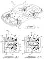
- FIG. 1is an illustration of an automobile using the automatically adjustable damping system in accordance with the present invention
- FIG. 2is a cross-sectional view of the automatic damping system with the acceleration valve incorporated into the upper end cap;
- FIGS. 3 a and 3 bdepict the acceleration valve as shown in FIG. 2 in its open and closed positions
- FIG. 4is a side view, partially in cross-section, of a shock absorber incorporating the automatically adjustable damping system in the base valve in accordance with another embodiment of the present invention.
- FIG. 1a vehicle incorporating a suspension system having the automatically adjustable shock absorbers in accordance with the present invention which is designated generally by the reference numeral 10 .
- Vehicle 10includes a rear suspension 12 , a front suspension 14 and a body 16 .
- Rear suspension 12has a transversely extending rear axle assembly (not shown) adapted to operatively support the vehicle's rear wheels 18 .
- the rear axle assemblyis operatively connected to body 16 by means of a pair of shock absorbers 20 and a pair of helical coil springs 22 .
- front suspension 14includes a transversely extending front axle assembly (not shown) to operatively support the vehicle's front wheels 24 .
- the front axle assemblyis operatively connected to body 16 by means of a second pair of shock absorbers 26 and by a pair of helical coil springs 28 .
- Shock absorbers 20 and 26serve to dampen the relative motion of the unsprung portion (i.e. front and rear suspensions 12 and 14 , respectively) and the sprung portion (i.e. body 16 ) of vehicle 10 .
- vehicle 10has been depicted as a passenger car having front and rear axle assemblies, shock absorbers 20 and 26 may be used with other types of vehicles or in other types of applications such as vehicles incorporating independent front and/or independent rear suspension systems.
- shock absorberas used herein is meant to refer to dampers in general and thus will include MacPherson struts.
- shock absorber 20is shown in greater detail. While FIG. 2 shows only shock absorber 20 , it is to be understood that shock absorber 26 also includes the piston, the base valving and the acceleration sensitive valving described below for shock absorber 20 . Shock absorber 26 only differs from shock absorber 20 in the way in which it is adapted to be connected to the sprung and unsprung portions of vehicle 10 . Shock absorber 20 comprises a pressure tube 30 , a piston 32 , a piston rod 34 , a reservoir tube 36 and a base valve assembly 40 .
- Pressure tube 30defines a working chamber 42 .
- Piston 32is slidably disposed within pressure tube 30 and divides working chamber 42 into an upper working chamber 44 and a lower working chamber 46 .
- a seal 48is disposed between piston 32 and pressure tube 30 to permit sliding movement of piston 32 with respect to pressure tube 30 without generating undue frictional forces as well as sealing upper working chamber 44 from lower working chamber 46 .
- Piston rod 34is attached to piston 32 and extends through upper working chamber 44 and through an upper end cap 50 which closes the upper end of both pressure tube 30 and reservoir tube 36 .
- a sealing system 52seals the interface between upper end cap 50 , reservoir tube 36 and piston rod 34 .
- the end of piston rod 34 opposite to piston 32is adapted to be secured to the sprung portion of vehicle 10 .
- Valving within piston 32controls the movement of fluid between upper working chamber 44 and lower working chamber 46 during movement of piston 32 within pressure tube 30 . Because piston rod 34 extends only through upper working chamber 44 and not lower working chamber 46 , movement of piston 32 with respect to pressure tube 30 causes a difference in the amount of fluid displaced in upper working chamber 44 than the amount of fluid displaced in lower working chamber 46 . This difference in the amount of fluid displaced is known as the “rod volume” and it flows through base valve assembly 40 .
- Reservoir tube 36surrounds pressure tube 30 to define a reservoir chamber 54 located between the tubes.
- the bottom end of reservoir tube 36is closed by a lower end cap 58 which is adapted to be connected to the unsprung portions of vehicle 10 .
- the upper end of reservoir tube 36is attached to upper end cap 50 .
- Base valve assembly 40is disposed between lower working chamber 46 and reservoir chamber 54 to control the flow of fluid between the two chambers.
- Acceleration sensitive valve assembly 60is incorporated into upper end cap 50 .
- Acceleration sensitive valve assembly 60comprises an outer housing 62 , a valve body 64 , a seal 66 , a spring or biasing member 68 and a retainer 70 .
- Upper end cap 50is secured to the end of the pressure tube 30 and the end of reservoir tube 36 by being pressed into pressure tube 30 and reservoir tube 36 or by other means well known in the art.
- Outer housing 62is press fit or otherwise secured within a bore 72 defined by upper end cap 50 .
- a fluid passage 74connects bore 72 with upper working chamber 44 .
- Outer housing 62defines a central cavity 76 which is in fluid communication with reservoir chamber 54 , bore 72 and passage 74 .
- Valve body 64is disposed within cavity 76 and seal 66 is disposed between outer housing 62 and valve body 64 to seal cavity 76 from reservoir chamber 54 .
- Spring 68is disposed between retainer 70 and valve body 64 to bias valve body 64 against seal 66 to maintain the seal between cavity 76 and reservoir chamber 54 .
- Base valve assembly 40includes a compression valve assembly 82 which opens under the influence of fluid pressure within lower working chamber 46 to allow the fluid to flow from lower working chamber 46 to reservoir chamber 54 .
- the damping forces generated by shock absorber 20 during a compression strokeare controlled by the design of compression valve assembly 82 .
- a rebound valve assembly 84 associated with piston 32opens under influence of fluid pressure within upper working chamber 44 to allow the flow of fluid from upper working chamber 44 to lower working chamber 46 .
- the damping forces generated by shock absorber 20 during a rebound strokeare controlled by the design of rebound valve assembly 84 . Due to the “rod volume” concept described above, during the rebound stroke fluid flow must also occur from reservoir chamber 54 to lower working chamber 46 .
- Base valve assembly 40includes a check valve assembly 86 which allows fluid flow from reservoir chamber 54 to lower working chamber 46 .
- Acceleration sensitive valve assembly 60functions during a rebound stroke to allow fluid flow from upper working chamber 44 to reservoir chamber 54 when shock absorber 20 experiences a prespecified amount of acceleration. This additional or secondary fluid flow reduces the stiffness of shock absorber 20 during the rebound stroke.
- reservoir tube 36 , pressure tube 30 and upper end cap 50are accelerated. This acceleration works on the mass of valve body 64 perpendicular to the longitudinal axis of valve body 64 , resulting in a moment about seal 66 due to the overhanging mass feature of valve body 64 .
- Spring 68also creates a moment about seal 66 .
- valve body 64becomes unstable and rotates about the edge of seal 66 resulting in a hydraulic leak path 88 as shown in FIG. 3 b .
- leak path 88When leak path 88 is open, hydraulic fluid flows from upper working chamber 44 , through passage 74 and through cavity 76 into reservoir chamber 54 . This flow reduces the hydraulic fluid pressure within upper working chamber 44 resulting in lower damping forces and a softer ride.
- valve body 64is such that hydraulic pressure within upper working chamber 44 will work to stabilize valve body 64 . As damper velocity increases and therefore hydraulic pressure, greater and greater wheel accelerations will be necessary to destabilize valve body 64 . This characteristic will tend to “filter” the wheel inputs that destabilize valve body 64 , effectively reducing a valve sensitivity to those inputs inducing a high frequency, low amplitude signal at the connection of shock absorber 20 to the unsprung mass of the vehicle.
- acceleration sensitive valve assembly 60is illustrated as being incorporated into base valve assembly 40 between lower working chamber 46 and reservoir chamber 54 . In this position, acceleration sensitive valve assembly 60 reacts to acceleration forces during a compression stroke to reduce the damping forces and provide a soft ride in the same manner as that described above when valve assembly 60 is located within upper end cap 50 .
- acceleration sensitive valve assembly 60in both upper end cap 50 and base valve assembly 40 to provide variable damping in both rebound and compression if desired.
Landscapes
- Engineering & Computer Science (AREA)
- General Engineering & Computer Science (AREA)
- Mechanical Engineering (AREA)
- Fluid-Damping Devices (AREA)
- Vehicle Body Suspensions (AREA)
Abstract
Description
Claims (8)
Priority Applications (5)
| Application Number | Priority Date | Filing Date | Title |
|---|---|---|---|
| US09/992,309US6581733B2 (en) | 2001-11-19 | 2001-11-19 | Acceleration sensitive damping for automotive dampers |
| BRPI0206325-5B1ABR0206325B1 (en) | 2001-11-19 | 2002-11-19 | DAMPER AND RESPONSIVE ACCELERATION ASSEMBLY |
| DE60208619TDE60208619T2 (en) | 2001-11-19 | 2002-11-19 | Acceleration sensitive damper |
| EP02025876AEP1312828B1 (en) | 2001-11-19 | 2002-11-19 | Acceleration sensitive damper |
| US10/425,127US6793049B2 (en) | 2001-11-19 | 2003-04-28 | Acceleration sensitive damping for automotive dampers |
Applications Claiming Priority (1)
| Application Number | Priority Date | Filing Date | Title |
|---|---|---|---|
| US09/992,309US6581733B2 (en) | 2001-11-19 | 2001-11-19 | Acceleration sensitive damping for automotive dampers |
Related Child Applications (1)
| Application Number | Title | Priority Date | Filing Date |
|---|---|---|---|
| US10/425,127DivisionUS6793049B2 (en) | 2001-11-19 | 2003-04-28 | Acceleration sensitive damping for automotive dampers |
Publications (2)
| Publication Number | Publication Date |
|---|---|
| US20030094339A1 US20030094339A1 (en) | 2003-05-22 |
| US6581733B2true US6581733B2 (en) | 2003-06-24 |
Family
ID=25538168
Family Applications (2)
| Application Number | Title | Priority Date | Filing Date |
|---|---|---|---|
| US09/992,309Expired - LifetimeUS6581733B2 (en) | 2001-11-19 | 2001-11-19 | Acceleration sensitive damping for automotive dampers |
| US10/425,127Expired - LifetimeUS6793049B2 (en) | 2001-11-19 | 2003-04-28 | Acceleration sensitive damping for automotive dampers |
Family Applications After (1)
| Application Number | Title | Priority Date | Filing Date |
|---|---|---|---|
| US10/425,127Expired - LifetimeUS6793049B2 (en) | 2001-11-19 | 2003-04-28 | Acceleration sensitive damping for automotive dampers |
Country Status (4)
| Country | Link |
|---|---|
| US (2) | US6581733B2 (en) |
| EP (1) | EP1312828B1 (en) |
| BR (1) | BR0206325B1 (en) |
| DE (1) | DE60208619T2 (en) |
Cited By (6)
| Publication number | Priority date | Publication date | Assignee | Title |
|---|---|---|---|---|
| US20030192753A1 (en)* | 2001-11-19 | 2003-10-16 | Karl Kazmirski | Acceleration sensitive damping for automotive dampers |
| US20040251097A1 (en)* | 2003-06-10 | 2004-12-16 | Barbison James M. | Adaptive shock damping control |
| US20060090973A1 (en)* | 2004-10-28 | 2006-05-04 | Michael Potas | Valve system controlled by rate of pressure change |
| US20070296163A1 (en)* | 2001-08-30 | 2007-12-27 | Fox Factory, Inc. | Inertia Valve Vehicle Suspension Assembly |
| US20140090941A1 (en)* | 2012-09-28 | 2014-04-03 | Hitachi Automotive Systems, Ltd. | Shock absorber |
| US11346422B2 (en) | 2001-08-30 | 2022-05-31 | Fox Factory, Inc. | Front bicycle suspension assembly with inertia valve |
Families Citing this family (15)
| Publication number | Priority date | Publication date | Assignee | Title |
|---|---|---|---|---|
| JP4181940B2 (en)* | 2003-08-01 | 2008-11-19 | カヤバ工業株式会社 | Hydraulic buffer with relief valve and vehicle height adjustment function |
| US7699146B1 (en) | 2006-04-02 | 2010-04-20 | Fox Factory, Inc. | Suspension damper having inertia valve and user adjustable pressure-relief |
| NL2002484C2 (en)* | 2009-02-03 | 2010-08-04 | Koni Bv | SWING DAMPER FOR A RAIL VEHICLE. |
| US9222538B2 (en) | 2009-04-16 | 2015-12-29 | Oneiric Systems, Inc. | Shock absorber having unidirectional fluid flow |
| MX2011010753A (en) | 2009-04-16 | 2012-01-12 | Oneiric Systems Inc | Shock absorber having unidirectional fluid flow. |
| US9365089B2 (en) | 2013-12-16 | 2016-06-14 | GM Global Technology Operations LLC | Method and apparatus for active suspension damping including negative stiffness |
| US9133900B2 (en) | 2013-12-16 | 2015-09-15 | GM Global Technology Operations LLC | Method and apparatus for suspension damping including negative stiffness employing a permanent magnet |
| US9370982B2 (en) | 2013-12-16 | 2016-06-21 | GM Global Technology Operations LLC | Method and apparatus for suspension damping including negative stiffness |
| DE102014204739A1 (en)* | 2014-03-14 | 2015-10-15 | Zf Friedrichshafen Ag | Vibration damper with a temperature-dependent variable bypass opening |
| US10086869B2 (en) | 2016-06-22 | 2018-10-02 | Tenneco Automotive Operating Company Inc. | Steering stabilizer for a motor vehicle |
| WO2018112513A1 (en)* | 2016-12-23 | 2018-06-28 | Vilo Niumeitolu | Anti-rolling and anti-pitching shock absorber |
| US10648527B2 (en) | 2017-04-24 | 2020-05-12 | Beijingwest Industries Co., Ltd. | Twin tube damper including a pressure rate sensitive system |
| KR102448779B1 (en)* | 2018-10-12 | 2022-09-28 | 히다치 아스테모 가부시키가이샤 | suspension control unit |
| US11668365B2 (en) | 2019-09-23 | 2023-06-06 | DRiV Automotive Inc. | Valve body for a damper |
| CN114087926A (en)* | 2021-10-28 | 2022-02-25 | 河北汉光重工有限责任公司 | Hydraulic shock absorber and target vehicle self-adaptive shock absorption system |
Citations (25)
| Publication number | Priority date | Publication date | Assignee | Title |
|---|---|---|---|---|
| US1281079A (en) | 1915-03-11 | 1918-10-08 | Willard T Sears | Shock-absorber. |
| US1992525A (en) | 1933-01-25 | 1935-02-26 | Gen Motors Corp | Shock absorber |
| US1995901A (en) | 1933-01-16 | 1935-03-26 | Gen Motors Corp | Shock absorber |
| US2015453A (en) | 1933-06-21 | 1935-09-24 | Gen Motors Corp | Shock absorber |
| US2098398A (en) | 1935-03-19 | 1937-11-09 | Mercier Jean | Shock absorber |
| US2140359A (en) | 1934-12-14 | 1938-12-13 | Westinghouse Electric & Mfg Co | Valve arrangement of inertia shock absorbers |
| US2252772A (en) | 1939-08-10 | 1941-08-19 | Katcher Morris | Hydraulic steering stabilizer |
| US2329803A (en) | 1941-10-06 | 1943-09-21 | Monroe Auto Equipment Co | Inertia controlled shock absorber |
| US2774448A (en) | 1953-04-28 | 1956-12-18 | Clifford T Hultin | Inertia responsive shock absorber |
| US2957703A (en) | 1956-08-16 | 1960-10-25 | Howard S Ross | Inertia responsive shock absorber arrangement for vehicle |
| US3127958A (en) | 1961-06-30 | 1964-04-07 | Ford Motor Co | Shock absorber with improved relief valve structure |
| US3338347A (en) | 1964-09-08 | 1967-08-29 | Girling Ltd | Hydraulic dampers for vehicle suspensions |
| US3414092A (en) | 1967-01-03 | 1968-12-03 | Frank H. Speckhart | Shock absorbing device |
| US3696894A (en) | 1971-07-02 | 1972-10-10 | Us Navy | Acceleration sensitive shock absorber valve |
| US4356898A (en) | 1979-11-20 | 1982-11-02 | Maremont Corporation | Valve assembly and reduced harshness shock absorber embodying the same |
| US4589528A (en)* | 1982-08-26 | 1986-05-20 | Fichtel & Sachs Ag | Double-tube vibration damper |
| US4902034A (en)* | 1988-09-06 | 1990-02-20 | General Motors Corporation | Electrically controlled shock absorber |
| US4917222A (en) | 1987-10-26 | 1990-04-17 | Bendix Espana | Shock absorber |
| US5285875A (en) | 1990-12-05 | 1994-02-15 | Nissan Research & Development, Inc. | Impact sensitive shock absorber |
| US5462140A (en) | 1992-05-05 | 1995-10-31 | Richardson Technologies, Ltd. | Acceleration sensitive shock absorber |
| US5598903A (en) | 1992-05-05 | 1997-02-04 | Ricor Racing & Development, L.P. | Acceleration sensitive flow sensitive mcpherson strut |
| US5992585A (en) | 1998-03-19 | 1999-11-30 | Tenneco Automotive Inc. | Acceleration sensitive damping for automotive dampers |
| US6119830A (en)* | 1992-10-08 | 2000-09-19 | Ricor Racing & Development, Lp | Flow sensitive, acceleration sensitive shock absorber |
| US6253888B1 (en)* | 1999-02-04 | 2001-07-03 | Gabriel Ride Control Products, Inc. | Shock absorber with acceleration sensitive damping control |
| US6334516B1 (en)* | 2000-04-27 | 2002-01-01 | Edelbrock | Acceleration sensitive twin tube shock absorber |
Family Cites Families (3)
| Publication number | Priority date | Publication date | Assignee | Title |
|---|---|---|---|---|
| US2098387A (en) | 1934-07-25 | 1937-11-09 | Klangfilm Gmbh | Film drive mechanism |
| JPH05141468A (en)* | 1991-11-20 | 1993-06-08 | Tokico Ltd | Damping force adjustable hydraulic shock absorber |
| US6581733B2 (en)* | 2001-11-19 | 2003-06-24 | Tenneco Automotive Inc. | Acceleration sensitive damping for automotive dampers |
- 2001
- 2001-11-19USUS09/992,309patent/US6581733B2/ennot_activeExpired - Lifetime
- 2002
- 2002-11-19EPEP02025876Apatent/EP1312828B1/ennot_activeExpired - Lifetime
- 2002-11-19DEDE60208619Tpatent/DE60208619T2/ennot_activeExpired - Lifetime
- 2002-11-19BRBRPI0206325-5B1Apatent/BR0206325B1/ennot_activeIP Right Cessation
- 2003
- 2003-04-28USUS10/425,127patent/US6793049B2/ennot_activeExpired - Lifetime
Patent Citations (25)
| Publication number | Priority date | Publication date | Assignee | Title |
|---|---|---|---|---|
| US1281079A (en) | 1915-03-11 | 1918-10-08 | Willard T Sears | Shock-absorber. |
| US1995901A (en) | 1933-01-16 | 1935-03-26 | Gen Motors Corp | Shock absorber |
| US1992525A (en) | 1933-01-25 | 1935-02-26 | Gen Motors Corp | Shock absorber |
| US2015453A (en) | 1933-06-21 | 1935-09-24 | Gen Motors Corp | Shock absorber |
| US2140359A (en) | 1934-12-14 | 1938-12-13 | Westinghouse Electric & Mfg Co | Valve arrangement of inertia shock absorbers |
| US2098398A (en) | 1935-03-19 | 1937-11-09 | Mercier Jean | Shock absorber |
| US2252772A (en) | 1939-08-10 | 1941-08-19 | Katcher Morris | Hydraulic steering stabilizer |
| US2329803A (en) | 1941-10-06 | 1943-09-21 | Monroe Auto Equipment Co | Inertia controlled shock absorber |
| US2774448A (en) | 1953-04-28 | 1956-12-18 | Clifford T Hultin | Inertia responsive shock absorber |
| US2957703A (en) | 1956-08-16 | 1960-10-25 | Howard S Ross | Inertia responsive shock absorber arrangement for vehicle |
| US3127958A (en) | 1961-06-30 | 1964-04-07 | Ford Motor Co | Shock absorber with improved relief valve structure |
| US3338347A (en) | 1964-09-08 | 1967-08-29 | Girling Ltd | Hydraulic dampers for vehicle suspensions |
| US3414092A (en) | 1967-01-03 | 1968-12-03 | Frank H. Speckhart | Shock absorbing device |
| US3696894A (en) | 1971-07-02 | 1972-10-10 | Us Navy | Acceleration sensitive shock absorber valve |
| US4356898A (en) | 1979-11-20 | 1982-11-02 | Maremont Corporation | Valve assembly and reduced harshness shock absorber embodying the same |
| US4589528A (en)* | 1982-08-26 | 1986-05-20 | Fichtel & Sachs Ag | Double-tube vibration damper |
| US4917222A (en) | 1987-10-26 | 1990-04-17 | Bendix Espana | Shock absorber |
| US4902034A (en)* | 1988-09-06 | 1990-02-20 | General Motors Corporation | Electrically controlled shock absorber |
| US5285875A (en) | 1990-12-05 | 1994-02-15 | Nissan Research & Development, Inc. | Impact sensitive shock absorber |
| US5462140A (en) | 1992-05-05 | 1995-10-31 | Richardson Technologies, Ltd. | Acceleration sensitive shock absorber |
| US5598903A (en) | 1992-05-05 | 1997-02-04 | Ricor Racing & Development, L.P. | Acceleration sensitive flow sensitive mcpherson strut |
| US6119830A (en)* | 1992-10-08 | 2000-09-19 | Ricor Racing & Development, Lp | Flow sensitive, acceleration sensitive shock absorber |
| US5992585A (en) | 1998-03-19 | 1999-11-30 | Tenneco Automotive Inc. | Acceleration sensitive damping for automotive dampers |
| US6253888B1 (en)* | 1999-02-04 | 2001-07-03 | Gabriel Ride Control Products, Inc. | Shock absorber with acceleration sensitive damping control |
| US6334516B1 (en)* | 2000-04-27 | 2002-01-01 | Edelbrock | Acceleration sensitive twin tube shock absorber |
Cited By (12)
| Publication number | Priority date | Publication date | Assignee | Title |
|---|---|---|---|---|
| US20070296163A1 (en)* | 2001-08-30 | 2007-12-27 | Fox Factory, Inc. | Inertia Valve Vehicle Suspension Assembly |
| US7520372B2 (en) | 2001-08-30 | 2009-04-21 | Fox Factory, Inc. | Inertia valve vehicle suspension assembly |
| US8297417B2 (en) | 2001-08-30 | 2012-10-30 | Fox Factory, Inc. | Front bicycle suspension assembly with inertia valve |
| US10316924B2 (en) | 2001-08-30 | 2019-06-11 | Fox Factory, Inc. | Front bicycle suspension assembly with inertia valve |
| US11346422B2 (en) | 2001-08-30 | 2022-05-31 | Fox Factory, Inc. | Front bicycle suspension assembly with inertia valve |
| US20030192753A1 (en)* | 2001-11-19 | 2003-10-16 | Karl Kazmirski | Acceleration sensitive damping for automotive dampers |
| US6793049B2 (en)* | 2001-11-19 | 2004-09-21 | Tenneco Automotive Operating Company, Inc. | Acceleration sensitive damping for automotive dampers |
| US20040251097A1 (en)* | 2003-06-10 | 2004-12-16 | Barbison James M. | Adaptive shock damping control |
| US6926128B2 (en)* | 2003-06-10 | 2005-08-09 | Arvin Technologies, Inc. | Adaptive shock damping control |
| US20060090973A1 (en)* | 2004-10-28 | 2006-05-04 | Michael Potas | Valve system controlled by rate of pressure change |
| US20140090941A1 (en)* | 2012-09-28 | 2014-04-03 | Hitachi Automotive Systems, Ltd. | Shock absorber |
| US9291229B2 (en)* | 2012-09-28 | 2016-03-22 | Hitachi Automotive Systems, Ltd. | Shock absorber |
Also Published As
| Publication number | Publication date |
|---|---|
| US20030192753A1 (en) | 2003-10-16 |
| DE60208619D1 (en) | 2006-04-06 |
| BR0206325B1 (en) | 2013-12-17 |
| EP1312828A2 (en) | 2003-05-21 |
| US6793049B2 (en) | 2004-09-21 |
| US20030094339A1 (en) | 2003-05-22 |
| DE60208619T2 (en) | 2006-08-17 |
| BR0206325A (en) | 2003-10-14 |
| EP1312828B1 (en) | 2006-01-11 |
| EP1312828A3 (en) | 2004-01-14 |
Similar Documents
| Publication | Publication Date | Title |
|---|---|---|
| US5992585A (en) | Acceleration sensitive damping for automotive dampers | |
| US6581733B2 (en) | Acceleration sensitive damping for automotive dampers | |
| US6460664B1 (en) | Independently tunable variable bleed orifice | |
| US7216747B2 (en) | Amplitude controlled orifice valving | |
| US6672436B1 (en) | Variable bleed orifice valving | |
| EP2158416B1 (en) | Junction bleed | |
| US6220409B1 (en) | Stroke dependent bypass | |
| US5924528A (en) | Load depending damping assembly | |
| GB2350877A (en) | Shock absorber having a blow off valve | |
| US6382372B1 (en) | Ported disc variable bleed orifice | |
| EP1167810B1 (en) | Shock absorber having ported plate low speed tunability | |
| WO2005045277A1 (en) | Compensated rod for a frequency dependent damper shock absorber | |
| US6644445B2 (en) | Floating port blocker | |
| US7097016B2 (en) | Fulcrum blow off valve for use in a shock absorber | |
| EP1664581B1 (en) | Shock absorber | |
| EP1314908A2 (en) | Hydraulic damper comprising a damping valve unit |
Legal Events
| Date | Code | Title | Description |
|---|---|---|---|
| AS | Assignment | Owner name:TENNECO AUTOMOTIVE, INC., ILLINOIS Free format text:ASSIGNMENT OF ASSIGNORS INTEREST;ASSIGNOR:KAZMIRSKI, KARL;REEL/FRAME:012328/0931 Effective date:20010802 | |
| STCF | Information on status: patent grant | Free format text:PATENTED CASE | |
| AS | Assignment | Owner name:TENNECO AUTOMOTIVE OPERATING COMPANY, INC., ILLINO Free format text:CHANGE OF NAME;ASSIGNOR:TENNECO AUTOMOTIVE INC.;REEL/FRAME:013868/0157 Effective date:19991105 | |
| AS | Assignment | Owner name:JPMORGAN CHASE BANK, AS ADMINISTRATIVE AGENT, TEXA Free format text:SECURITY AGREEMENT;ASSIGNOR:TENNECO AUTOMOTIVE OPERATING COMPANY INC. (DELAWARE CORPORATION);REEL/FRAME:014475/0131 Effective date:20030728 | |
| AS | Assignment | Owner name:WACHOVIA BANK, NATIONAL ASSOCIATION, AS COLLATERAL Free format text:SECURITY AGREEMENT;ASSIGNORS:TENNECO AUTOMOTIVE INC.;TENNECO AUTOMOTIVE OPERATING COMPANY INC.;TENNECO INTERNATIONAL HOLDING CORP.;AND OTHERS;REEL/FRAME:015017/0658 Effective date:20030619 | |
| FPAY | Fee payment | Year of fee payment:4 | |
| AS | Assignment | Owner name:JPMORGAN CHASE BANK,NEW YORK Free format text:AMENDMENT TO SECURITY INTEREST IN UNITED STATES PATENTS;ASSIGNORS:TENNECO AUTOMOTIVE OPERATING COMPANY INC.;TENNECO INTERNATIONAL HOLDING CORP.;TENNECO GLOBAL HOLDINGS INC.;AND OTHERS;REEL/FRAME:019009/0247 Effective date:20070312 Owner name:JPMORGAN CHASE BANK, NEW YORK Free format text:AMENDMENT TO SECURITY INTEREST IN UNITED STATES PATENTS;ASSIGNORS:TENNECO AUTOMOTIVE OPERATING COMPANY INC.;TENNECO INTERNATIONAL HOLDING CORP.;TENNECO GLOBAL HOLDINGS INC.;AND OTHERS;REEL/FRAME:019009/0247 Effective date:20070312 | |
| AS | Assignment | Owner name:CLEVITE INDUSTRIES INC., ILLINOIS Free format text:RELEASE BY SECURED PARTY;ASSIGNOR:U.S. BANK NATIONAL ASSOCIATION (AS SUCCESSOR IN INTEREST TO WACHOVIA BANK, NATIONAL ASSOCIATION);REEL/FRAME:024973/0130 Effective date:20100902 Owner name:TENNECO AUTOMOTIVE OPERATING COMPANY INC., ILLINOI Free format text:RELEASE BY SECURED PARTY;ASSIGNOR:U.S. BANK NATIONAL ASSOCIATION (AS SUCCESSOR IN INTEREST TO WACHOVIA BANK, NATIONAL ASSOCIATION);REEL/FRAME:024973/0130 Effective date:20100902 Owner name:TENNECO GLOBAL HOLDINGS INC., ILLINOIS Free format text:RELEASE BY SECURED PARTY;ASSIGNOR:U.S. BANK NATIONAL ASSOCIATION (AS SUCCESSOR IN INTEREST TO WACHOVIA BANK, NATIONAL ASSOCIATION);REEL/FRAME:024973/0130 Effective date:20100902 Owner name:TENNECO INTERNATIONAL HOLDING CORP., ILLINOIS Free format text:RELEASE BY SECURED PARTY;ASSIGNOR:U.S. BANK NATIONAL ASSOCIATION (AS SUCCESSOR IN INTEREST TO WACHOVIA BANK, NATIONAL ASSOCIATION);REEL/FRAME:024973/0130 Effective date:20100902 Owner name:THE PULLMAN COMPANY, ILLINOIS Free format text:RELEASE BY SECURED PARTY;ASSIGNOR:U.S. BANK NATIONAL ASSOCIATION (AS SUCCESSOR IN INTEREST TO WACHOVIA BANK, NATIONAL ASSOCIATION);REEL/FRAME:024973/0130 Effective date:20100902 Owner name:TENNECO AUTOMOTIVE INC. (NOW KNOWN AS TENNECO INC. Free format text:RELEASE BY SECURED PARTY;ASSIGNOR:U.S. BANK NATIONAL ASSOCIATION (AS SUCCESSOR IN INTEREST TO WACHOVIA BANK, NATIONAL ASSOCIATION);REEL/FRAME:024973/0130 Effective date:20100902 Owner name:TMC TEXAS INC., ILLINOIS Free format text:RELEASE BY SECURED PARTY;ASSIGNOR:U.S. BANK NATIONAL ASSOCIATION (AS SUCCESSOR IN INTEREST TO WACHOVIA BANK, NATIONAL ASSOCIATION);REEL/FRAME:024973/0130 Effective date:20100902 | |
| FPAY | Fee payment | Year of fee payment:8 | |
| FPAY | Fee payment | Year of fee payment:12 | |
| AS | Assignment | Owner name:JPMORGAN CHASE BANK, N.A., AS ADMINISTRATIVE AGENT, ILLINOIS Free format text:GRANT OF SECURITY INTEREST IN PATENT RIGHTS;ASSIGNOR:TENNECO AUTOMOTIVE OPERATING COMPANY INC.;REEL/FRAME:042809/0515 Effective date:20170512 Owner name:JPMORGAN CHASE BANK, N.A., AS ADMINISTRATIVE AGENT Free format text:GRANT OF SECURITY INTEREST IN PATENT RIGHTS;ASSIGNOR:TENNECO AUTOMOTIVE OPERATING COMPANY INC.;REEL/FRAME:042809/0515 Effective date:20170512 | |
| AS | Assignment | Owner name:WILMINGTON TRUST, NATIONAL ASSOCIATION, AS COLLATERAL TRUSTEE, MINNESOTA Free format text:CONFIRMATORY GRANT OF SECURITY INTERESTS IN UNITED STATES PATENTS;ASSIGNORS:TENNECO INC.;TENNECO AUTOMOTIVE OPERATING COMPANY INC.;TENNECO INTERNATIONAL HOLDING CORP.;AND OTHERS;REEL/FRAME:047223/0001 Effective date:20181001 Owner name:WILMINGTON TRUST, NATIONAL ASSOCIATION, AS COLLATE Free format text:CONFIRMATORY GRANT OF SECURITY INTERESTS IN UNITED STATES PATENTS;ASSIGNORS:TENNECO INC.;TENNECO AUTOMOTIVE OPERATING COMPANY INC.;TENNECO INTERNATIONAL HOLDING CORP.;AND OTHERS;REEL/FRAME:047223/0001 Effective date:20181001 | |
| AS | Assignment | Owner name:TENNECO AUTOMOTIVE OPERATING COMPANY INC., ILLINOIS Free format text:RELEASE BY SECURED PARTY;ASSIGNOR:JPMORGAN CHASE BANK, N.A.;REEL/FRAME:048099/0716 Effective date:20181001 Owner name:TENNECO AUTOMOTIVE OPERATING COMPANY INC., ILLINOI Free format text:RELEASE BY SECURED PARTY;ASSIGNOR:JPMORGAN CHASE BANK, N.A.;REEL/FRAME:048099/0716 Effective date:20181001 | |
| AS | Assignment | Owner name:WILMINGTON TRUST, NATIONAL ASSOCIATION, MINNESOTA Free format text:SECURITY AGREEMENT;ASSIGNORS:TENNECO INC.;THE PULLMAN COMPANY;FEDERAL-MOGUL IGNITION LLC;AND OTHERS;REEL/FRAME:054555/0592 Effective date:20201130 | |
| AS | Assignment | Owner name:TENNECO AUTOMOTIVE OPERATING COMPANY INC., ILLINOIS Free format text:CONFIRMATION OF TERMINATION AND RELEASE OF SECURITY INTEREST IN PATENT RIGHTS (R/F 14475/0131);ASSIGNOR:JPMORGAN CHASE BANK, N.A., AS ADMINISTRATIVE AGENT;REEL/FRAME:055426/0159 Effective date:20210226 Owner name:CLEVITE INDUSTRIES INC., ILLINOIS Free format text:CONFIRMATION OF TERMINATION AND RELEASE OF SECURITY INTEREST IN PATENT RIGHTS (R/F 19009/0247);ASSIGNOR:JPMORGAN CHASE BANK, N.A., AS ADMINISTRATIVE AGENT;REEL/FRAME:055429/0284 Effective date:20210226 Owner name:TENNECO AUTOMOTIVE OPERATING COMPANY INC., ILLINOIS Free format text:CONFIRMATION OF TERMINATION AND RELEASE OF SECURITY INTEREST IN PATENT RIGHTS (R/F 19009/0247);ASSIGNOR:JPMORGAN CHASE BANK, N.A., AS ADMINISTRATIVE AGENT;REEL/FRAME:055429/0284 Effective date:20210226 Owner name:THE PULLMAN COMPANY, ILLINOIS Free format text:CONFIRMATION OF TERMINATION AND RELEASE OF SECURITY INTEREST IN PATENT RIGHTS (R/F 19009/0247);ASSIGNOR:JPMORGAN CHASE BANK, N.A., AS ADMINISTRATIVE AGENT;REEL/FRAME:055429/0284 Effective date:20210226 Owner name:TENNECO GLOBAL HOLDINGS INC., ILLINOIS Free format text:CONFIRMATION OF TERMINATION AND RELEASE OF SECURITY INTEREST IN PATENT RIGHTS (R/F 19009/0247);ASSIGNOR:JPMORGAN CHASE BANK, N.A., AS ADMINISTRATIVE AGENT;REEL/FRAME:055429/0284 Effective date:20210226 Owner name:TMC TEXAS INC., ILLINOIS Free format text:CONFIRMATION OF TERMINATION AND RELEASE OF SECURITY INTEREST IN PATENT RIGHTS (R/F 19009/0247);ASSIGNOR:JPMORGAN CHASE BANK, N.A., AS ADMINISTRATIVE AGENT;REEL/FRAME:055429/0284 Effective date:20210226 Owner name:TENNECO INTERNATIONAL HOLDING CORP., ILLINOIS Free format text:CONFIRMATION OF TERMINATION AND RELEASE OF SECURITY INTEREST IN PATENT RIGHTS (R/F 19009/0247);ASSIGNOR:JPMORGAN CHASE BANK, N.A., AS ADMINISTRATIVE AGENT;REEL/FRAME:055429/0284 Effective date:20210226 Owner name:TENNECO INC. (FORMERLY KNOWN AS TENNECO AUTOMOTIVE INC.), ILLINOIS Free format text:CONFIRMATION OF TERMINATION AND RELEASE OF SECURITY INTEREST IN PATENT RIGHTS (R/F 19009/0247);ASSIGNOR:JPMORGAN CHASE BANK, N.A., AS ADMINISTRATIVE AGENT;REEL/FRAME:055429/0284 Effective date:20210226 | |
| AS | Assignment | Owner name:WILMINGTON TRUST, NATIONAL ASSOCIATION, MINNESOTA Free format text:SECURITY AGREEMENT;ASSIGNORS:TENNECO INC.;TENNECO AUTOMOTIVE OPERATING COMPANY INC.;THE PULLMAN COMPANY;AND OTHERS;REEL/FRAME:055626/0065 Effective date:20210317 | |
| AS | Assignment | Owner name:DRIV AUTOMOTIVE INC., MICHIGAN Free format text:RELEASE BY SECURED PARTY;ASSIGNOR:WILMINGTON TRUST, NATIONAL ASSOCIATION;REEL/FRAME:061971/0156 Effective date:20221117 Owner name:FEDERAL-MOGUL CHASSIS LLC, MICHIGAN Free format text:RELEASE BY SECURED PARTY;ASSIGNOR:WILMINGTON TRUST, NATIONAL ASSOCIATION;REEL/FRAME:061971/0156 Effective date:20221117 Owner name:FEDERAL-MOGUL WORLD WIDE LLC, MICHIGAN Free format text:RELEASE BY SECURED PARTY;ASSIGNOR:WILMINGTON TRUST, NATIONAL ASSOCIATION;REEL/FRAME:061971/0156 Effective date:20221117 Owner name:FEDERAL-MOGUL MOTORPARTS LLC, MICHIGAN Free format text:RELEASE BY SECURED PARTY;ASSIGNOR:WILMINGTON TRUST, NATIONAL ASSOCIATION;REEL/FRAME:061971/0156 Effective date:20221117 Owner name:FEDERAL-MOGUL PRODUCTS US LLC, MICHIGAN Free format text:RELEASE BY SECURED PARTY;ASSIGNOR:WILMINGTON TRUST, NATIONAL ASSOCIATION;REEL/FRAME:061971/0156 Effective date:20221117 Owner name:FEDERAL-MOGUL POWERTRAIN LLC, MICHIGAN Free format text:RELEASE BY SECURED PARTY;ASSIGNOR:WILMINGTON TRUST, NATIONAL ASSOCIATION;REEL/FRAME:061971/0156 Effective date:20221117 Owner name:FEDERAL-MOGUL IGNITION LLC, MICHIGAN Free format text:RELEASE BY SECURED PARTY;ASSIGNOR:WILMINGTON TRUST, NATIONAL ASSOCIATION;REEL/FRAME:061971/0156 Effective date:20221117 Owner name:THE PULLMAN COMPANY, OHIO Free format text:RELEASE BY SECURED PARTY;ASSIGNOR:WILMINGTON TRUST, NATIONAL ASSOCIATION;REEL/FRAME:061971/0156 Effective date:20221117 Owner name:TENNECO AUTOMOTIVE OPERATING COMPANY INC., ILLINOIS Free format text:RELEASE BY SECURED PARTY;ASSIGNOR:WILMINGTON TRUST, NATIONAL ASSOCIATION;REEL/FRAME:061971/0156 Effective date:20221117 Owner name:TENNECO INC., ILLINOIS Free format text:RELEASE BY SECURED PARTY;ASSIGNOR:WILMINGTON TRUST, NATIONAL ASSOCIATION;REEL/FRAME:061971/0156 Effective date:20221117 Owner name:FEDERAL-MOGUL PRODUCTS US LLC, MICHIGAN Free format text:RELEASE BY SECURED PARTY;ASSIGNOR:WILMINGTON TRUST, NATIONAL ASSOCIATION;REEL/FRAME:061975/0218 Effective date:20221117 Owner name:FEDERAL-MOGUL FINANCING CORPORATION, MICHIGAN Free format text:RELEASE BY SECURED PARTY;ASSIGNOR:WILMINGTON TRUST, NATIONAL ASSOCIATION;REEL/FRAME:061975/0218 Effective date:20221117 Owner name:FEDERAL-MOGUL FILTRATION LLC, MICHIGAN Free format text:RELEASE BY SECURED PARTY;ASSIGNOR:WILMINGTON TRUST, NATIONAL ASSOCIATION;REEL/FRAME:061975/0218 Effective date:20221117 Owner name:BECK ARNLEY HOLDINGS LLC, MICHIGAN Free format text:RELEASE BY SECURED PARTY;ASSIGNOR:WILMINGTON TRUST, NATIONAL ASSOCIATION;REEL/FRAME:061975/0218 Effective date:20221117 Owner name:FEDERAL-MOGUL SEVIERVILLE, LLC, MICHIGAN Free format text:RELEASE BY SECURED PARTY;ASSIGNOR:WILMINGTON TRUST, NATIONAL ASSOCIATION;REEL/FRAME:061975/0218 Effective date:20221117 Owner name:FEDERAL-MOGUL VALVE TRAIN INTERNATIONAL LLC, MICHIGAN Free format text:RELEASE BY SECURED PARTY;ASSIGNOR:WILMINGTON TRUST, NATIONAL ASSOCIATION;REEL/FRAME:061975/0218 Effective date:20221117 Owner name:F-M TSC REAL ESTATE HOLDINGS LLC, MICHIGAN Free format text:RELEASE BY SECURED PARTY;ASSIGNOR:WILMINGTON TRUST, NATIONAL ASSOCIATION;REEL/FRAME:061975/0218 Effective date:20221117 Owner name:F-M MOTORPARTS TSC LLC, MICHIGAN Free format text:RELEASE BY SECURED PARTY;ASSIGNOR:WILMINGTON TRUST, NATIONAL ASSOCIATION;REEL/FRAME:061975/0218 Effective date:20221117 Owner name:FEDERAL-MOGUL CHASSIS LLC, MICHIGAN Free format text:RELEASE BY SECURED PARTY;ASSIGNOR:WILMINGTON TRUST, NATIONAL ASSOCIATION;REEL/FRAME:061975/0218 Effective date:20221117 Owner name:FEDERAL-MOGUL MOTORPARTS LLC, MICHIGAN Free format text:RELEASE BY SECURED PARTY;ASSIGNOR:WILMINGTON TRUST, NATIONAL ASSOCIATION;REEL/FRAME:061975/0218 Effective date:20221117 Owner name:FEDERAL-MOGUL IGNITION LLC, MICHIGAN Free format text:RELEASE BY SECURED PARTY;ASSIGNOR:WILMINGTON TRUST, NATIONAL ASSOCIATION;REEL/FRAME:061975/0218 Effective date:20221117 Owner name:FEDERAL-MOGUL PISTON RINGS, LLC, MICHIGAN Free format text:RELEASE BY SECURED PARTY;ASSIGNOR:WILMINGTON TRUST, NATIONAL ASSOCIATION;REEL/FRAME:061975/0218 Effective date:20221117 Owner name:FEDERAL-MOGUL POWERTRAIN IP LLC, MICHIGAN Free format text:RELEASE BY SECURED PARTY;ASSIGNOR:WILMINGTON TRUST, NATIONAL ASSOCIATION;REEL/FRAME:061975/0218 Effective date:20221117 Owner name:FEDERAL-MOGUL POWERTRAIN LLC, MICHIGAN Free format text:RELEASE BY SECURED PARTY;ASSIGNOR:WILMINGTON TRUST, NATIONAL ASSOCIATION;REEL/FRAME:061975/0218 Effective date:20221117 Owner name:MUZZY-LYON AUTO PARTS LLC, ILLINOIS Free format text:RELEASE BY SECURED PARTY;ASSIGNOR:WILMINGTON TRUST, NATIONAL ASSOCIATION;REEL/FRAME:061975/0218 Effective date:20221117 Owner name:FELT PRODUCTS MFG. CO. LLC, ILLINOIS Free format text:RELEASE BY SECURED PARTY;ASSIGNOR:WILMINGTON TRUST, NATIONAL ASSOCIATION;REEL/FRAME:061975/0218 Effective date:20221117 Owner name:FEDERAL-MOGUL WORLD WIDE LLC, MICHIGAN Free format text:RELEASE BY SECURED PARTY;ASSIGNOR:WILMINGTON TRUST, NATIONAL ASSOCIATION;REEL/FRAME:061975/0218 Effective date:20221117 Owner name:CARTER AUTOMOTIVE COMPANY LLC, ILLINOIS Free format text:RELEASE BY SECURED PARTY;ASSIGNOR:WILMINGTON TRUST, NATIONAL ASSOCIATION;REEL/FRAME:061975/0218 Effective date:20221117 Owner name:TMC TEXAS INC., ILLINOIS Free format text:RELEASE BY SECURED PARTY;ASSIGNOR:WILMINGTON TRUST, NATIONAL ASSOCIATION;REEL/FRAME:061975/0218 Effective date:20221117 Owner name:CLEVITE INDUSTRIES INC., OHIO Free format text:RELEASE BY SECURED PARTY;ASSIGNOR:WILMINGTON TRUST, NATIONAL ASSOCIATION;REEL/FRAME:061975/0218 Effective date:20221117 Owner name:TENNECO GLOBAL HOLDINGS INC., ILLINOIS Free format text:RELEASE BY SECURED PARTY;ASSIGNOR:WILMINGTON TRUST, NATIONAL ASSOCIATION;REEL/FRAME:061975/0218 Effective date:20221117 Owner name:THE PULLMAN COMPANY, OHIO Free format text:RELEASE BY SECURED PARTY;ASSIGNOR:WILMINGTON TRUST, NATIONAL ASSOCIATION;REEL/FRAME:061975/0218 Effective date:20221117 Owner name:TENNECO INTERNATIONAL HOLDING CORP., ILLINOIS Free format text:RELEASE BY SECURED PARTY;ASSIGNOR:WILMINGTON TRUST, NATIONAL ASSOCIATION;REEL/FRAME:061975/0218 Effective date:20221117 Owner name:TENNECO AUTOMOTIVE OPERATING COMPANY INC., ILLINOIS Free format text:RELEASE BY SECURED PARTY;ASSIGNOR:WILMINGTON TRUST, NATIONAL ASSOCIATION;REEL/FRAME:061975/0218 Effective date:20221117 Owner name:TENNECO INC., ILLINOIS Free format text:RELEASE BY SECURED PARTY;ASSIGNOR:WILMINGTON TRUST, NATIONAL ASSOCIATION;REEL/FRAME:061975/0218 Effective date:20221117 Owner name:DRIV AUTOMOTIVE INC., MICHIGAN Free format text:RELEASE BY SECURED PARTY;ASSIGNOR:WILMINGTON TRUST, NATIONAL ASSOCIATION;REEL/FRAME:061975/0031 Effective date:20221117 Owner name:FEDERAL-MOGUL CHASSIS LLC, MICHIGAN Free format text:RELEASE BY SECURED PARTY;ASSIGNOR:WILMINGTON TRUST, NATIONAL ASSOCIATION;REEL/FRAME:061975/0031 Effective date:20221117 Owner name:FEDERAL-MOGUL WORLD WIDE LLC, MICHIGAN Free format text:RELEASE BY SECURED PARTY;ASSIGNOR:WILMINGTON TRUST, NATIONAL ASSOCIATION;REEL/FRAME:061975/0031 Effective date:20221117 Owner name:FEDERAL-MOGUL PRODUCTS US LLC, MICHIGAN Free format text:RELEASE BY SECURED PARTY;ASSIGNOR:WILMINGTON TRUST, NATIONAL ASSOCIATION;REEL/FRAME:061975/0031 Effective date:20221117 Owner name:FEDERAL-MOGUL POWERTRAIN LLC, MICHIGAN Free format text:RELEASE BY SECURED PARTY;ASSIGNOR:WILMINGTON TRUST, NATIONAL ASSOCIATION;REEL/FRAME:061975/0031 Effective date:20221117 Owner name:FEDERAL-MOGUL IGNITION LLC, MICHIGAN Free format text:RELEASE BY SECURED PARTY;ASSIGNOR:WILMINGTON TRUST, NATIONAL ASSOCIATION;REEL/FRAME:061975/0031 Effective date:20221117 Owner name:THE PULLMAN COMPANY, OHIO Free format text:RELEASE BY SECURED PARTY;ASSIGNOR:WILMINGTON TRUST, NATIONAL ASSOCIATION;REEL/FRAME:061975/0031 Effective date:20221117 Owner name:TENNECO AUTOMOTIVE OPERATING COMPANY INC., ILLINOIS Free format text:RELEASE BY SECURED PARTY;ASSIGNOR:WILMINGTON TRUST, NATIONAL ASSOCIATION;REEL/FRAME:061975/0031 Effective date:20221117 Owner name:TENNECO INC., ILLINOIS Free format text:RELEASE BY SECURED PARTY;ASSIGNOR:WILMINGTON TRUST, NATIONAL ASSOCIATION;REEL/FRAME:061975/0031 Effective date:20221117 | |
| AS | Assignment | Owner name:CITIBANK, N.A., AS COLLATERAL AGENT, NEW YORK Free format text:NOTICE OF GRANT OF SECURITY INTEREST IN PATENTS (FIRST LIEN);ASSIGNORS:DRIV AUTOMOTIVE INC.;FEDERAL-MOGUL CHASSIS LLC;FEDERAL-MOGUL IGNITION LLC;AND OTHERS;REEL/FRAME:061989/0689 Effective date:20221117 | |
| AS | Assignment | Owner name:CITIBANK, N.A., AS COLLATERAL AGENT, NEW YORK Free format text:PATENT SECURITY AGREEMENT (ABL);ASSIGNORS:TENNECO INC.;DRIV AUTOMOTIVE INC.;FEDERAL-MOGUL CHASSIS LLC;AND OTHERS;REEL/FRAME:063268/0506 Effective date:20230406 |