US6580927B1 - Wireless mobile telephone system with voice-dialing telephone instruments and DTMF capability - Google Patents
Wireless mobile telephone system with voice-dialing telephone instruments and DTMF capabilityDownload PDFInfo
- Publication number
- US6580927B1 US6580927B1US09/953,766US95376601AUS6580927B1US 6580927 B1US6580927 B1US 6580927B1US 95376601 AUS95376601 AUS 95376601AUS 6580927 B1US6580927 B1US 6580927B1
- Authority
- US
- United States
- Prior art keywords
- wireless telephone
- telephone
- instrument
- wireless
- instruments
- Prior art date
- Legal status (The legal status is an assumption and is not a legal conclusion. Google has not performed a legal analysis and makes no representation as to the accuracy of the status listed.)
- Expired - Fee Related
Links
Images


Classifications
- H—ELECTRICITY
- H04—ELECTRIC COMMUNICATION TECHNIQUE
- H04M—TELEPHONIC COMMUNICATION
- H04M17/00—Prepayment of wireline communication systems, wireless communication systems or telephone systems
- H—ELECTRICITY
- H04—ELECTRIC COMMUNICATION TECHNIQUE
- H04B—TRANSMISSION
- H04B1/00—Details of transmission systems, not covered by a single one of groups H04B3/00 - H04B13/00; Details of transmission systems not characterised by the medium used for transmission
- H04B1/38—Transceivers, i.e. devices in which transmitter and receiver form a structural unit and in which at least one part is used for functions of transmitting and receiving
- H04B1/40—Circuits
- H04B1/403—Circuits using the same oscillator for generating both the transmitter frequency and the receiver local oscillator frequency
- H04B1/406—Circuits using the same oscillator for generating both the transmitter frequency and the receiver local oscillator frequency with more than one transmission mode, e.g. analog and digital modes
- H—ELECTRICITY
- H04—ELECTRIC COMMUNICATION TECHNIQUE
- H04M—TELEPHONIC COMMUNICATION
- H04M17/00—Prepayment of wireline communication systems, wireless communication systems or telephone systems
- H04M17/005—Disposable prepaid communication devices
- H—ELECTRICITY
- H04—ELECTRIC COMMUNICATION TECHNIQUE
- H04M—TELEPHONIC COMMUNICATION
- H04M17/00—Prepayment of wireline communication systems, wireless communication systems or telephone systems
- H04M17/02—Coin-freed or check-freed systems, e.g. mobile- or card-operated phones, public telephones or booths
- H04M17/026—Constructional features
- H—ELECTRICITY
- H04—ELECTRIC COMMUNICATION TECHNIQUE
- H04M—TELEPHONIC COMMUNICATION
- H04M17/00—Prepayment of wireline communication systems, wireless communication systems or telephone systems
- H04M17/20—Prepayment of wireline communication systems, wireless communication systems or telephone systems with provision for recharging the prepaid account or card, or for credit establishment
- H—ELECTRICITY
- H04—ELECTRIC COMMUNICATION TECHNIQUE
- H04M—TELEPHONIC COMMUNICATION
- H04M3/00—Automatic or semi-automatic exchanges
- H04M3/42—Systems providing special services or facilities to subscribers
- H04M3/42204—Arrangements at the exchange for service or number selection by voice
- H—ELECTRICITY
- H04—ELECTRIC COMMUNICATION TECHNIQUE
- H04W—WIRELESS COMMUNICATION NETWORKS
- H04W4/00—Services specially adapted for wireless communication networks; Facilities therefor
- H04W4/24—Accounting or billing
- H—ELECTRICITY
- H04—ELECTRIC COMMUNICATION TECHNIQUE
- H04M—TELEPHONIC COMMUNICATION
- H04M1/00—Substation equipment, e.g. for use by subscribers
- H04M1/26—Devices for calling a subscriber
- H04M1/27—Devices whereby a plurality of signals may be stored simultaneously
- H04M1/271—Devices whereby a plurality of signals may be stored simultaneously controlled by voice recognition
- H—ELECTRICITY
- H04—ELECTRIC COMMUNICATION TECHNIQUE
- H04M—TELEPHONIC COMMUNICATION
- H04M1/00—Substation equipment, e.g. for use by subscribers
- H04M1/60—Substation equipment, e.g. for use by subscribers including speech amplifiers
- H04M1/6033—Substation equipment, e.g. for use by subscribers including speech amplifiers for providing handsfree use or a loudspeaker mode in telephone sets
- H04M1/6041—Portable telephones adapted for handsfree use
- H—ELECTRICITY
- H04—ELECTRIC COMMUNICATION TECHNIQUE
- H04M—TELEPHONIC COMMUNICATION
- H04M2207/00—Type of exchange or network, i.e. telephonic medium, in which the telephonic communication takes place
- H04M2207/18—Type of exchange or network, i.e. telephonic medium, in which the telephonic communication takes place wireless networks
Definitions
- the present inventionrelates to wireless mobile telephone systems incorporating telephone instruments that are capable of being simple in form, e.g. keyless and battery-less, relatively inexpensive and conveniently available for flexible use, both for conversational and DTMF communication.
- wireless mobile telephoneshave come into extensive use supported by various forms of central equipment.
- wireless telephone instrumentssometimes called “mobile stations” (MS) may be accommodated for example by geographically defined cells.
- MSmobile stations
- Such systemsafford the capability for wireless telephone instruments to communicate with other telephone terminals through the public telephone network while physically roving between locations.
- BScentral equipment
- MSCmobile switching center
- a weak link in mobile telephone communicationsinvolves power for the telephone instrument, e.g., the battery.
- the user of a mobile telephone instrumentmust always be concerned with the state of the instrument's battery. If an instrument is not used for a time, concern grows for the charge state of the battery.
- certain charging patternsmay be detrimental to the battery power cycle. For example, to maintain an effective power cycle of a battery, it may be important to fully discharge the battery before recharging. Accordingly, maintaining a mobile telephone battery charged for operation sometimes is inconvenient. Essentially without careful planning, a mobile instrument user may be faced with a discharged battery when the need for the instrument is most urgent.
- the power pack or battery of a mobile telephone instrumenttypically accounts for a considerable portion of the instrument's weight, cost and volume.
- the battery of a mobile telephone instrumentnot only presents a limitation on the use of such instruments but also imposes constraints on the design of such instruments.
- aspects of the present inventionare based on recognizing certain distinct features of wireless mobile telephone systems.
- the very nature of mobile systemsrenders the individual telephone instruments: more susceptible to loss or misplacement, more susceptible to misuse, more likely to be individually used (by only a single person), more likely to be unused for long intervals of time, more likely to be intended for emergency or urgent use, more likely to be intended for use in unconventional locations and so on.
- wireless telephone instrumentsare provided with a flexible and convenient power adapter for use with alternative power sources, e.g. automotive power (vehicular) or AC power as available in most buildings (structural).
- alternative power sourcese.g. automotive power (vehicular) or AC power as available in most buildings (structural).
- instruments as disclosed hereinare simplified by eliminating the keypad and utilizing voice dialing.
- Voice recognition apparatus in the system central equipmentfacilitates voice dialing and additionally enables digital communication.
- a controlled switching capabilityis provided in the central system to selectively enable communication from the instruments to, or through the public switched telephone network either in a conversational mode (speech) or a DTMF mode (data).
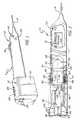
- FIG. 1is perspective view showing a wireless telephone instrument in accordance with the present invention and for use in a system in accordance with the present invention
- FIG. 2is a sectional view taken lengthwise through the instrument of FIG. 1;
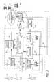
- FIG. 3is block diagram of a system in accordance with the present invention showing plural telephone instruments and central station components for use with a public switched telephone network;
- FIG. 4is a flow chart detailing certain operations of the system of FIG. 3 .
- the instrument TIincludes an elongate tubular hand piece 10 (housing) shown matingly engaged with a power pod unit 12 .
- the hand piece 10is telescopically engaged (frictionally) with the pod unit 12 when the instrument TI is not in use.
- the pod unit 12is separated from the hand piece 10 and coupled to a power source (for example, either conventional “110 V,” AC power or low voltage D.C. power, e.g., automotive).
- a cable(treated below) is provided from the pod unit 12 (when engaged to a power connection) supplying appropriate power to the handpiece 10 while allowing the connected handpiece 10 to be positioned near a user's face.
- an antenna 14is fixed at the end (right) of the hand piece 10 .
- perforations 16 in the hand piece 10pass sound to the user's ear.
- a pocket clip 18 and a pilot lamp 20are provided.
- the pod unit 12includes a block 21 , somewhat in the shape of a semi cylinder, extended at its plane surface, and which contains prongs or bayonet contact elements 22 of an AC plug shown withdrawn or recessed in the pod unit 12 .
- the contact elements 22are carried on a frame (not shown in FIG. 1) which incorporates a slide button 24 fixed in an elongated opening 26 that extends parallel to the cylindrical axis. Accordingly, moving the slide button 24 away from the hand piece 10 positions the contact elements 22 out of the pod unit 12 for engagement with a conventional AC receptacle.
- the pod unit 12may engage the traditional “cigarette lighter” coupling in widespread automotive use to provide DC power.
- a hemispherical distal end 30 of the pod unit 12is shaped hemispherically for male engagement with a conventional automotive power outlet (cigarette lighter receptacle—not shown).
- the distal end 30is integral with a cylindrical portion 32 of the pod 12 and the block 21 .
- the distal end 30 of the pod unit 12accommodates DC coupling while the opposed end 36 accommodates an AC coupling.
- the block 21 and integral structure of the pod unit 12may be formed of plastic non conductive material.
- the end 30when not in use, the end 30 (right) is matingly received in the hand piece 10 .
- the domed hemisphereis terminated by a concentric metallic contact 38 .
- the contact 38provides one DC power connection, while a second connection is provided by an annular band contact 40 , concentrically mounted on the cylinder portion 32 . Accordingly, insertion of the distal end 30 and the cylindrical portion 32 into an energized automotive receptacle provides direct current (DC) power.
- DCdirect current
- the electrical connection provided by the contacts 38 and 40is through wires 42 and 44 which are coupled to a converter 54 from which a cable pair 46 emerges and are wrapped to form a coil 48 when the instrument TI is not in use. Note that the coil 48 dwells in an annular space 50 defined between the hand piece 10 and the block 21 when the two are matingly engaged.
- the opposed end 51 of the cable 46is electrically connected to power an electronics package 52 mounted in the tubular hand piece 10 .
- connectors or wires 42 and 44are coupled to the converter 54 which alternatively may be connected to a source of alternating current (AC) power through expansion wires 56 and a plug structure 58 .
- the plug structure 58incorporates a yoke 60 of insulating material which supports if the AC contact elements 22 that are electrically connected to the wires 56 .
- the yoke 60is supported on rails 64 allowing it to move axially with respect to the pod unit 12 so as to extend the prongs or contact elements 22 for electrical engagement with a conventional AC receptacle.
- the prongs 22 or the contacts 38 and 40may engage mating connections (not shown) to a source of power.
- the power converter 54is energized to power the electronics package 52 with appropriate electrical energy.
- the power pod unit 12may be disengaged from the hand piece 10 , simply by force to engage an electrical power connection through the cable 46 (e.g. vehicular or structural), allowing freedom of movement for the hand piece 10 .
- the power converter 54receives either AC power (prongs 22 and wires 56 ) or DC power (contact 38 and band 40 ) functioning to provide the appropriate power for the electronics package 52 .
- the lamp 20(FIG. 1) is energized. Note that when the instrument TI is not in use, the cable 46 is simply wrapped about the cylindrical portion 32 and concentrated as the coil 48 in an annular space defined between the pod 12 and the hand piece 10 .
- the hand piece 10functions as a housing for the electronics package 52 along with other transceiver elements including an earphone 70 (FIG. 1, under the perforations 16 ). Additionally, the hand piece 10 carries a microphone 72 , which is also connected to the electronics package 52 and which is fixed in a cylindrical wall 74 of the hand piece 10 .
- the individual instrument TIwould be one of a multitude capable of interfacing wireless central station apparatus for connection to another telephonic terminal through the public switched telephone network.
- the connectionwould be accomplished through central equipment (interfacing the public switched telephone network) by the user of the instrument TI speaking the numbers of a called telephone terminal.
- normal voice communicationcould proceed.
- the situationsometimes arises when, after communication is established with another terminal, it is desirable to communicate from the wireless instrument, e.g. the instrument TI, using DTMF or other forms of non-vocal signals.
- FIG. 3a multitude of wireless mobile telephone instruments P 1 -Pn are represented (left).
- the instruments P 1 -PNinterface a central wireless system C to accomplish telephonic connection through a switched telecommunications network S with any of a plurality of other telephonic terminals generally indicated as remote terminals TR 1 -TRn.
- the other terminals TRI-TRnmay include computers and the like.
- the communication operationinvolves a caller using one of the terminals P 1 -Pn to interface the central system C for the entry of spoken numerals representative of a called number.
- the system Cconverts or translates the spoken numerals to DTMF signals and accordingly actuates the network S to establish a telephonic communication between the calling terminal, e.g. P 1 and a called number, e.g. terminal TR 1 .
- the wireless instrument P 1may communicate with the called terminal TR 1 , using either voice communication or digital (DTMF) communication. Consequently, the caller, for example at the instrument P 1 , can effectively interface a computer, as to obtain information, participate in a collective activity, accomplish any of a multitude of transactions and so on.
- the voice-actuated wireless instruments P 1 -Pnare capable of effective computer telephonic interface (CTI).
- the individual wireless instruments P 1 -Pncommunicate through radio links with a transceiver platform 80 as illustrated.
- the platformincorporates antenna structure 82 to facilitate individual radio links and is capable of simultaneously accommodating many individual instruments from the group of instruments P 1 -Pn.
- the central wireless system Cincludes the capability to concurrently process and accommodate communication from an active plurality of the units or instruments P 1 -Pn simultaneously through a large number of individual lines L 1 through Ln.
- the platform 80may also include some processing or voice capability. As the platform 80 and other elements of the central wireless system C are provided, the various capabilities may shift from one element to another.
- a single blockis shown to accommodate one line L 1 of many lines L 1 -Ln.
- all of the lines L 1 -Lnare to be accommodated; however, several alternatives exist to simply replicating the implementation blocks of FIG. 3 .
- the capability illustratively coupled to the line L 1is afforded for each of the other lines as by multiplexing, parallel operation and so on.
- the line L 1is coupled to a telephone instrument interface or bridge 84 which serves to obtain the called telephone number and to indirectly provide appropriate dialing signals to the switched telecommunication network S to accomplish the desired connection.
- dialing signalsmay for example take the form of Touch-Tone signals or DTMF signals.
- the bridge 84may incorporate an audio response unit for prompting callers to speak called telephone numbers, along with voice decoder apparatus for translating spoken called numbers into keypad signals, e.g. DTMF, which are provided to the network S.
- the bridge 84Upon accomplishing a desired connection, the bridge 84 simply couples the calling instrument to the established connection through the network S.
- the bridge 84prompts the user to provide the called telephone number, receives the number (vocal signals) acknowledges receipt of the number and provides a signal in a line 92 to reset a binary 94 .
- communicationis either keypad (digital) or voice. Accordingly, the output of the binary is high in one of the lines 95 or 96 .
- a dial tone or other signalmay be transmitted to the instrument P 1 .
- an acknowledgment signalis provided. That is, the spoken numerals (digits) of the called number are represented by received audio signals passed from the bridge 84 through the line 88 to a gate 99 which is qualified by the high binary signal in the line 95 and accordingly passes the voice signals to a voice-DTMF detector or translator 101 .
- individual DTMF signalsare passed from the translator 101 back to the platform 80 and then transmitted back to the instrument P 1 to acknowledge the digits.
- the translated digit signale.g. DTMF
- the network Sto accomplish a dial up connection.
- the bridge 84senses the dial up connection through a diode 116 and provides a high binary signal in a line 104 to set the binary 94 for vocal (conversation) communication.
- the operationis to pass audio signals representative of voice. That is, the operation after establishing a connection from calling terminal P 1 to called terminal TRn is to set the vocal conversation state with the binary 94 set.
- Such a mode of operationis referred to as the “conversation state.”
- networksno longer receives DTMF signals. That is, the network S is no longer responsive to dialing signals as in a DTMF form. Consequently, if voice communication were the caller's objective, such could be pursued at the present stage.
- the logic circuit 90monitors the operation for commands by the caller to initiate digital communication.
- audio from the instrument P 1passes through: the line L 1 , the bridge 84 , the line 88 , the gate 98 , the diode 100 and the line 103 to the network S.
- Similar signals from the network Spass through: the line 103 , the diode 116 , the line 88 and the bridge 84 to the L 1 .
- a block 110represents. the process step of connecting the called and calling terminals as explained above.
- a block 112indicates the predefined process step of initiating a conversational state, establishing a vocal path for the communication link through the gate 98 (FIG. 3) as explained above. If however, the digital or DTMF state is desired, the binary 94 must be reset to establish a data path.
- the operating mode or stateis altered to digital by the caller giving a command signal.
- the change of stateis accomplished by the user at the instrument P 1 speaking a series of words, e.g. “no” in rapid succession.
- the manual input operationis represented by a block 120 .
- the spoken series of the word “no”is detected by a detector 122 (center right) to provide a pulse or binary high signal to reset the binary 94 .
- the DTMF or digital stateis represented by a block 124 in FIG. 4 .
- the operation of the system in the system in the digital state to accommodate communication with keypad signals, for example DTMF signalswill now be considered.
- the gate 98is “closed” and the gate 99 is “open”; both under control of the binary 94 .
- the gates 98 and 99serve as switches to route the communication signals as desired.
- the computer TRnproduces voice signals for cuing the caller at the instrument P 1 .
- the voice signalsmight take the form: “Please enter your social security number.” Audio signals representative of such a cue would pass through the network S, the line 103 , the diode 116 , the line 88 , the bridge 84 and be transmitted by the platform 82 to the instrument P 1 .
- the callerspeaks the individual social security numerals, e.g. “529-20-4731.”
- the spoken digit wordsare received by the platform 80 , passed through the bridge 84 and the gate 99 to the voice translator 101 .
- the translator 101sequentially translates or converts the spoken numerals to representative DTMF signals.
- the represented numeralsare acknowledged to the caller and DTMF signals representative of the social security number (529-20-4731) are provided through the diode 100 , the line 103 and the network S to the computer TRn. Accordingly, a digital interface communication is accomplished in accordance herewith.
- the callergives a command signal, herein speaks a series of words indicating the numeral “seven.” The detailed operation of accomplishing the switch or change of state will now be considered.
- a “7” s detector 130senses the series of seven's and sets the binary 94 . That is, the binary 94 is set in a state to provide a high signal level in the line 96 . Accordingly, the gate 99 is “closed” and the gate 98 is “opened” returning the system to the audio or voice state.
- the operationis graphically represented in FIG. 4 by the block 126 .
- the callermay repeatedly switch between the two operating states. Also, it is to be recognized that any of a variety of sensors may be employed in combination with specific program instructions to switch a change in state.
- the voice or conversation stateis conventional in that no signaling occurs.
- a form of a state signalis provided to the user, for example the person using the instrument P 1 .
- any of a variety of signalscould be utilized to manifest the digital state.
- a simple low-frequency intermittent toneis provided during intervals of silence.
- a silence or null detector 130is connected to the line 103 to provide a high-level binary signal at a time when the line is null (carries no signals) the null-indicating signal is provided to a gate 132 which is also connected to receive the reset signal (digital state) from the binary 94 . Accordingly, during the digital state, the gate 132 is qualified to provide a high output through a line 139 to an intermittent tone generator 136 . Essentially, the generator 136 is simply keyed by the received signal to provide an intermittent low-frequency tone to the line 88 . Consequently, when the system is in the keypad or digital state, during periods of silence, a low-frequency tone is provided through the bridge 84 to the platform 80 for transmission to the caller at the instrument P 1 . Thus, the digital state is manifest as a convenient reminder to the caller.
Landscapes
- Engineering & Computer Science (AREA)
- Signal Processing (AREA)
- Computer Networks & Wireless Communication (AREA)
- Computer Security & Cryptography (AREA)
- Business, Economics & Management (AREA)
- Accounting & Taxation (AREA)
- Mobile Radio Communication Systems (AREA)
Abstract
Description
Claims (27)
Priority Applications (2)
| Application Number | Priority Date | Filing Date | Title |
|---|---|---|---|
| US09/953,766US6580927B1 (en) | 1997-06-19 | 2001-09-16 | Wireless mobile telephone system with voice-dialing telephone instruments and DTMF capability |
| US10/190,058US6751482B1 (en) | 1997-06-19 | 2002-07-02 | Wireless mobile telephone system with alternative power instruments and DTMF Capability |
Applications Claiming Priority (4)
| Application Number | Priority Date | Filing Date | Title |
|---|---|---|---|
| US08/878,864US6049710A (en) | 1997-06-19 | 1997-06-19 | Wireless prepaid telephone system with dispensable instruments |
| US08/955,338US6298250B1 (en) | 1997-06-19 | 1997-10-21 | Wireless prepaid telephone system with extended capability |
| US09/311,795US6292675B1 (en) | 1997-10-21 | 1999-05-13 | Wireless mobile telephone system with voice-dialing telephone instruments and DTMF capability |
| US09/953,766US6580927B1 (en) | 1997-06-19 | 2001-09-16 | Wireless mobile telephone system with voice-dialing telephone instruments and DTMF capability |
Related Parent Applications (2)
| Application Number | Title | Priority Date | Filing Date |
|---|---|---|---|
| US08/878,864Continuation-In-PartUS6049710A (en) | 1997-06-19 | 1997-06-19 | Wireless prepaid telephone system with dispensable instruments |
| US09/311,795ContinuationUS6292675B1 (en) | 1997-06-19 | 1999-05-13 | Wireless mobile telephone system with voice-dialing telephone instruments and DTMF capability |
Related Child Applications (1)
| Application Number | Title | Priority Date | Filing Date |
|---|---|---|---|
| US10/190,058DivisionUS6751482B1 (en) | 1997-06-19 | 2002-07-02 | Wireless mobile telephone system with alternative power instruments and DTMF Capability |
Publications (1)
| Publication Number | Publication Date |
|---|---|
| US6580927B1true US6580927B1 (en) | 2003-06-17 |
Family
ID=25496690
Family Applications (2)
| Application Number | Title | Priority Date | Filing Date |
|---|---|---|---|
| US09/311,795Expired - Fee RelatedUS6292675B1 (en) | 1997-06-19 | 1999-05-13 | Wireless mobile telephone system with voice-dialing telephone instruments and DTMF capability |
| US09/953,766Expired - Fee RelatedUS6580927B1 (en) | 1997-06-19 | 2001-09-16 | Wireless mobile telephone system with voice-dialing telephone instruments and DTMF capability |
Family Applications Before (1)
| Application Number | Title | Priority Date | Filing Date |
|---|---|---|---|
| US09/311,795Expired - Fee RelatedUS6292675B1 (en) | 1997-06-19 | 1999-05-13 | Wireless mobile telephone system with voice-dialing telephone instruments and DTMF capability |
Country Status (1)
| Country | Link |
|---|---|
| US (2) | US6292675B1 (en) |
Cited By (4)
| Publication number | Priority date | Publication date | Assignee | Title |
|---|---|---|---|---|
| US6845234B1 (en)* | 1997-06-19 | 2005-01-18 | Byard G. Nilsson | Wireless telephone system with discardable keyless instruments |
| US6917802B1 (en)* | 1997-06-19 | 2005-07-12 | Byard G. Nilsson | Mobile keyless telephone instruments and wireless telecommunications system having voice dialing and voice programming capabilities |
| US20080152094A1 (en)* | 2006-12-22 | 2008-06-26 | Perlmutter S Michael | Method for Selecting Interactive Voice Response Modes Using Human Voice Detection Analysis |
| US8086283B2 (en) | 2002-08-08 | 2011-12-27 | Parker Stephen B | Wireless child communication device |
Families Citing this family (11)
| Publication number | Priority date | Publication date | Assignee | Title |
|---|---|---|---|---|
| US6298250B1 (en) | 1997-06-19 | 2001-10-02 | Kimberly Nanette Engen | Wireless prepaid telephone system with extended capability |
| US6862463B1 (en) | 1997-06-19 | 2005-03-01 | Byard G. Nilsson | Wireless telephone system with information service |
| US6993321B1 (en) | 1997-06-19 | 2006-01-31 | Nilsson Byard G | Wireless telephone system with mobile instruments for outgoing calls |
| US6292675B1 (en) | 1997-10-21 | 2001-09-18 | Byard G. Nilsson | Wireless mobile telephone system with voice-dialing telephone instruments and DTMF capability |
| US6049710A (en) | 1997-06-19 | 2000-04-11 | Kimberley Nanette Engen | Wireless prepaid telephone system with dispensable instruments |
| US6751482B1 (en) | 1997-06-19 | 2004-06-15 | Byard G. Nilsson | Wireless mobile telephone system with alternative power instruments and DTMF Capability |
| GB0120672D0 (en)* | 2001-08-24 | 2001-10-17 | Mitel Knowledge Corp | Intermediate voice and DTMF detector device for improved speech recognition utilisation and penetration |
| US6892083B2 (en)* | 2001-09-05 | 2005-05-10 | Vocera Communications Inc. | Voice-controlled wireless communications system and method |
| US7953447B2 (en) | 2001-09-05 | 2011-05-31 | Vocera Communications, Inc. | Voice-controlled communications system and method using a badge application |
| US7343005B2 (en)* | 2002-05-29 | 2008-03-11 | Time Warner Cable, A Division Of Time Warner Entertainment Company, L.P. | Method and apparatus for voice-over IP services triggered by off-hook event |
| US7518631B2 (en)* | 2005-06-28 | 2009-04-14 | Microsoft Corporation | Audio-visual control system |
Citations (64)
| Publication number | Priority date | Publication date | Assignee | Title |
|---|---|---|---|---|
| US3688126A (en) | 1971-01-29 | 1972-08-29 | Paul R Klein | Sound-operated, yes-no responsive switch |
| US4007364A (en) | 1974-05-02 | 1977-02-08 | Hoshidenki-Seizo Kabushiki Kaisha | Writing instrument with calculator |
| US4320256A (en) | 1979-11-27 | 1982-03-16 | Freeman Michael J | Verbally interactive telephone interrogation system with selectible variable decision tree |
| US4475189A (en) | 1982-05-27 | 1984-10-02 | At&T Bell Laboratories | Automatic interactive conference arrangement |
| US4596900A (en) | 1983-06-23 | 1986-06-24 | Jackson Philip S | Phone-line-linked, tone-operated control device |
| US4611094A (en) | 1983-12-01 | 1986-09-09 | At&T Bell Laboratories | Method for customer definable telephone capability |
| US4731811A (en) | 1984-10-02 | 1988-03-15 | Regie Nationale Des Usines Renault | Radiotelephone system, particularly for motor vehicles |
| US4829514A (en) | 1987-03-18 | 1989-05-09 | International Telesystems Corporation | Digital voice recording and reproduction and telephone network signalling using direct storage in RAM of PCM encoded data |
| US4856066A (en) | 1986-11-06 | 1989-08-08 | Lemelson Jerome H | Speech communication system and method |
| US4870686A (en) | 1987-10-19 | 1989-09-26 | Motorola, Inc. | Method for entering digit sequences by voice command |
| US4879744A (en) | 1985-07-10 | 1989-11-07 | Omron Tateisi Electronics Co. | Card-operated telephone |
| US4969180A (en) | 1989-05-18 | 1990-11-06 | I.I.N.V. Computing Ltd. | Cordless pen telephone handset |
| US5042063A (en) | 1987-09-11 | 1991-08-20 | Kabushiki Kaisha Toshiba | Telephone apparatus with voice activated dialing function |
| US5153902A (en) | 1990-04-27 | 1992-10-06 | Telefonaktiebolaget L M Ericsson | Multi-exchange paging system for locating a mobile telephone in a wide area telephone network |
| US5195090A (en) | 1991-07-09 | 1993-03-16 | At&T Bell Laboratories | Wireless access telephone-to-telephone network interface architecture |
| US5222121A (en) | 1989-06-19 | 1993-06-22 | Nec Corporation | Voice recognition dialing unit |
| US5274695A (en) | 1991-01-11 | 1993-12-28 | U.S. Sprint Communications Company Limited Partnership | System for verifying the identity of a caller in a telecommunications network |
| US5297183A (en) | 1992-04-13 | 1994-03-22 | Vcs Industries, Inc. | Speech recognition system for electronic switches in a cellular telephone or personal communication network |
| US5297194A (en) | 1990-05-15 | 1994-03-22 | Vcs Industries, Inc. | Simultaneous speaker-independent voice recognition and verification over a telephone network |
| US5353336A (en)* | 1992-08-24 | 1994-10-04 | At&T Bell Laboratories | Voice directed communications system archetecture |
| US5353335A (en) | 1992-08-03 | 1994-10-04 | At&T Bell Laboratories | Multilingual prepaid telephone system |
| US5369685A (en) | 1991-03-07 | 1994-11-29 | Sprint Communications Company L.P. | Voice-activated telephone directory and call placement system |
| US5377256A (en) | 1985-11-25 | 1994-12-27 | Cellular Communications Corporation | Apparatus and method for a cellular freeway emergency telephone |
| US5420912A (en) | 1993-02-27 | 1995-05-30 | Alcatel N.V. | Telephone having portable voice control module for playing back speech or performing a hands-free telephone function |
| US5440620A (en) | 1992-08-28 | 1995-08-08 | At&T Corp. | Telecommunications system subscriber profile updating |
| US5450479A (en) | 1992-12-30 | 1995-09-12 | At&T Corp. | Method and apparatus for facilitating the making of card calls |
| US5461664A (en) | 1993-04-07 | 1995-10-24 | Cappadona; Steven | Emergency wireless telephone |
| WO1996003001A1 (en) | 1994-07-20 | 1996-02-01 | Sima Cohn | Cellular phone of the disposable type |
| US5509060A (en) | 1993-11-19 | 1996-04-16 | At&T Corp. | Network-accessible intelligent telephone service |
| US5509049A (en) | 1994-10-31 | 1996-04-16 | Voicetech Communications, Inc. | Automatic dialing of number received from directory assistance from within cellular system |
| US5541977A (en) | 1993-03-11 | 1996-07-30 | At&T Corp. | Method and apparatus for preventing wireless fraud |
| US5574771A (en) | 1994-08-15 | 1996-11-12 | Lucent Technologies Inc. | Integrated communication system |
| US5592535A (en) | 1993-04-16 | 1997-01-07 | Alcatel Sel Aktiengesellschaft | Mobile-radio network with debit accounts |
| US5599204A (en)* | 1995-05-01 | 1997-02-04 | Glassford; Joseph B. | Voltage adapter |
| US5602900A (en) | 1990-01-18 | 1997-02-11 | Kabushiki Kaisha Toshiba | Radio Telecommunication apparatus |
| US5640689A (en) | 1995-03-31 | 1997-06-17 | Compaq Computer Corp. | Communications apparatus with antenna switching based on antenna rotation |
| US5710813A (en) | 1995-03-28 | 1998-01-20 | Olympus Optical Co., Ltd. | Digital voice recording/reproducing apparatus |
| US5719926A (en) | 1994-06-10 | 1998-02-17 | Communications Product Development, Inc. | Prepaid long-distance telephone service system with flexible operating parameters |
| US5754645A (en) | 1992-01-21 | 1998-05-19 | Motorola, Inc. | Electronic apparatus having keyless control |
| US5778313A (en) | 1995-12-08 | 1998-07-07 | Cellexis International, Inc. | Pre-paid cellular telephone system |
| US5790636A (en) | 1989-05-31 | 1998-08-04 | Marshall; Marvin E. | Telephone travel card system under the control of its customers |
| US5797101A (en) | 1996-01-31 | 1998-08-18 | Motorola, Inc. | Radiotelephone subscriber unit having a generic phone number |
| US5802466A (en) | 1996-06-28 | 1998-09-01 | Mci Communications Corporation | Personal communication device voice mail notification apparatus and method |
| US5812945A (en) | 1995-12-22 | 1998-09-22 | Pitney Bowes Inc. | Metered payment cellular telephone communication system |
| US5815807A (en) | 1996-01-31 | 1998-09-29 | Motorola, Inc. | Disposable wireless communication device adapted to prevent fraud |
| US5826185A (en) | 1994-11-16 | 1998-10-20 | Banana Cellular, Inc. | Cellular phone system wherein the air time use is predetermined |
| US5828738A (en) | 1996-12-20 | 1998-10-27 | Spaeth; Robert D. | Mobile telephone-vehicle meter device interface |
| US5832371A (en)* | 1996-11-01 | 1998-11-03 | Ericsson, Inc. | Modular radiotelephone |
| US5835570A (en) | 1996-06-26 | 1998-11-10 | At&T Corp | Voice-directed telephone directory with voice access to directory assistance |
| US5845218A (en) | 1997-02-28 | 1998-12-01 | Altschul; Randice-Lisa | Disposable wireless telephone and method |
| US5850599A (en) | 1992-09-25 | 1998-12-15 | Ecs Enhanced Cellular Systems Manufacturing Inc. | Portable cellular telephone with credit card debit system |
| US5854975A (en) | 1994-12-23 | 1998-12-29 | Freedom Wireless, Inc. | Prepaid security cellular telecommunications system |
| US5867796A (en) | 1995-04-28 | 1999-02-02 | Nec Corporation | Portable telephone set capable of being put in a holding mode by operation of a vibration unit which is for announcing reception of an incoming call to a user |
| US5884188A (en) | 1996-09-18 | 1999-03-16 | Ericsson Inc. | Received signal selection system for combined pager/cellular telephone apparatus |
| WO1999014928A1 (en) | 1997-09-15 | 1999-03-25 | Intellivoice Communications, Inc. | Simplified training of voice dialing systems |
| US5963859A (en) | 1997-07-18 | 1999-10-05 | Polaroid Corporation | Wireless communication device with replaceable battery and prepaid calling time |
| US5966654A (en) | 1996-11-01 | 1999-10-12 | Ericsson Inc. | Recyclable cellular telephone and method and apparatus for supporting the use of a recyclable cellular telephone within a cellular telephone network acting as a theme park communicator/scheduler |
| US6049710A (en) | 1997-06-19 | 2000-04-11 | Kimberley Nanette Engen | Wireless prepaid telephone system with dispensable instruments |
| US6138036A (en) | 1997-03-13 | 2000-10-24 | Oki Telecom, Inc. | Wireless telephone with voice data interface mode |
| US6167118A (en) | 1997-12-30 | 2000-12-26 | Dsc Telecom L.P. | Method and a system for by-passing a receiver-off-hook timer for voice dialing systems and for supporting spoken digit dialing |
| US6167251A (en) | 1998-10-02 | 2000-12-26 | Telespree Communications | Keyless portable cellular phone system having remote voice recognition |
| US6292675B1 (en) | 1997-10-21 | 2001-09-18 | Byard G. Nilsson | Wireless mobile telephone system with voice-dialing telephone instruments and DTMF capability |
| US6298250B1 (en) | 1997-06-19 | 2001-10-02 | Kimberly Nanette Engen | Wireless prepaid telephone system with extended capability |
| US6308053B1 (en) | 1997-06-19 | 2001-10-23 | Byard G. Nilsson | Recyclable wireless telephone unit with a secured activation switch |
- 1999
- 1999-05-13USUS09/311,795patent/US6292675B1/ennot_activeExpired - Fee Related
- 2001
- 2001-09-16USUS09/953,766patent/US6580927B1/ennot_activeExpired - Fee Related
Patent Citations (70)
| Publication number | Priority date | Publication date | Assignee | Title |
|---|---|---|---|---|
| US3688126A (en) | 1971-01-29 | 1972-08-29 | Paul R Klein | Sound-operated, yes-no responsive switch |
| US4007364A (en) | 1974-05-02 | 1977-02-08 | Hoshidenki-Seizo Kabushiki Kaisha | Writing instrument with calculator |
| US4320256A (en) | 1979-11-27 | 1982-03-16 | Freeman Michael J | Verbally interactive telephone interrogation system with selectible variable decision tree |
| US4475189A (en) | 1982-05-27 | 1984-10-02 | At&T Bell Laboratories | Automatic interactive conference arrangement |
| US4596900A (en) | 1983-06-23 | 1986-06-24 | Jackson Philip S | Phone-line-linked, tone-operated control device |
| US4596900B2 (en) | 1983-06-23 | 1997-08-26 | Philip S Jackson | Phone-line-linked tone-operated control device |
| US4596900B1 (en) | 1983-06-23 | 1995-10-10 | Philip S Jackson | Phone-link linked tone-operated control device |
| US4611094A (en) | 1983-12-01 | 1986-09-09 | At&T Bell Laboratories | Method for customer definable telephone capability |
| US4731811A (en) | 1984-10-02 | 1988-03-15 | Regie Nationale Des Usines Renault | Radiotelephone system, particularly for motor vehicles |
| US4879744A (en) | 1985-07-10 | 1989-11-07 | Omron Tateisi Electronics Co. | Card-operated telephone |
| US5377256A (en) | 1985-11-25 | 1994-12-27 | Cellular Communications Corporation | Apparatus and method for a cellular freeway emergency telephone |
| US4856066A (en) | 1986-11-06 | 1989-08-08 | Lemelson Jerome H | Speech communication system and method |
| US4829514A (en) | 1987-03-18 | 1989-05-09 | International Telesystems Corporation | Digital voice recording and reproduction and telephone network signalling using direct storage in RAM of PCM encoded data |
| US5042063A (en) | 1987-09-11 | 1991-08-20 | Kabushiki Kaisha Toshiba | Telephone apparatus with voice activated dialing function |
| US4870686A (en) | 1987-10-19 | 1989-09-26 | Motorola, Inc. | Method for entering digit sequences by voice command |
| US4969180A (en) | 1989-05-18 | 1990-11-06 | I.I.N.V. Computing Ltd. | Cordless pen telephone handset |
| US5790636A (en) | 1989-05-31 | 1998-08-04 | Marshall; Marvin E. | Telephone travel card system under the control of its customers |
| US5222121A (en) | 1989-06-19 | 1993-06-22 | Nec Corporation | Voice recognition dialing unit |
| US5602900A (en) | 1990-01-18 | 1997-02-11 | Kabushiki Kaisha Toshiba | Radio Telecommunication apparatus |
| US5153902A (en) | 1990-04-27 | 1992-10-06 | Telefonaktiebolaget L M Ericsson | Multi-exchange paging system for locating a mobile telephone in a wide area telephone network |
| US5297194A (en) | 1990-05-15 | 1994-03-22 | Vcs Industries, Inc. | Simultaneous speaker-independent voice recognition and verification over a telephone network |
| US5499288A (en) | 1990-05-15 | 1996-03-12 | Voice Control Systems, Inc. | Simultaneous voice recognition and verification to allow access to telephone network services |
| US5274695A (en) | 1991-01-11 | 1993-12-28 | U.S. Sprint Communications Company Limited Partnership | System for verifying the identity of a caller in a telecommunications network |
| US5369685A (en) | 1991-03-07 | 1994-11-29 | Sprint Communications Company L.P. | Voice-activated telephone directory and call placement system |
| US5195090A (en) | 1991-07-09 | 1993-03-16 | At&T Bell Laboratories | Wireless access telephone-to-telephone network interface architecture |
| US5754645A (en) | 1992-01-21 | 1998-05-19 | Motorola, Inc. | Electronic apparatus having keyless control |
| US5659597A (en) | 1992-04-13 | 1997-08-19 | Voice Control Systems, Inc. | Speech recognition system for electronic switches in a non-wireline communications network |
| US5297183A (en) | 1992-04-13 | 1994-03-22 | Vcs Industries, Inc. | Speech recognition system for electronic switches in a cellular telephone or personal communication network |
| US6157848A (en) | 1992-04-13 | 2000-12-05 | Philips Electronics North America Corporation | Speech recognition system for electronic switches in a non-wireline communications network |
| US5353335A (en) | 1992-08-03 | 1994-10-04 | At&T Bell Laboratories | Multilingual prepaid telephone system |
| US5353336A (en)* | 1992-08-24 | 1994-10-04 | At&T Bell Laboratories | Voice directed communications system archetecture |
| US5440620A (en) | 1992-08-28 | 1995-08-08 | At&T Corp. | Telecommunications system subscriber profile updating |
| US5850599A (en) | 1992-09-25 | 1998-12-15 | Ecs Enhanced Cellular Systems Manufacturing Inc. | Portable cellular telephone with credit card debit system |
| US5450479A (en) | 1992-12-30 | 1995-09-12 | At&T Corp. | Method and apparatus for facilitating the making of card calls |
| US5420912A (en) | 1993-02-27 | 1995-05-30 | Alcatel N.V. | Telephone having portable voice control module for playing back speech or performing a hands-free telephone function |
| US5541977A (en) | 1993-03-11 | 1996-07-30 | At&T Corp. | Method and apparatus for preventing wireless fraud |
| US5461664A (en) | 1993-04-07 | 1995-10-24 | Cappadona; Steven | Emergency wireless telephone |
| US5592535A (en) | 1993-04-16 | 1997-01-07 | Alcatel Sel Aktiengesellschaft | Mobile-radio network with debit accounts |
| US5509060A (en) | 1993-11-19 | 1996-04-16 | At&T Corp. | Network-accessible intelligent telephone service |
| US5719926A (en) | 1994-06-10 | 1998-02-17 | Communications Product Development, Inc. | Prepaid long-distance telephone service system with flexible operating parameters |
| WO1996003001A1 (en) | 1994-07-20 | 1996-02-01 | Sima Cohn | Cellular phone of the disposable type |
| US5574771A (en) | 1994-08-15 | 1996-11-12 | Lucent Technologies Inc. | Integrated communication system |
| US5509049A (en) | 1994-10-31 | 1996-04-16 | Voicetech Communications, Inc. | Automatic dialing of number received from directory assistance from within cellular system |
| US5826185A (en) | 1994-11-16 | 1998-10-20 | Banana Cellular, Inc. | Cellular phone system wherein the air time use is predetermined |
| US5854975A (en) | 1994-12-23 | 1998-12-29 | Freedom Wireless, Inc. | Prepaid security cellular telecommunications system |
| US5710813A (en) | 1995-03-28 | 1998-01-20 | Olympus Optical Co., Ltd. | Digital voice recording/reproducing apparatus |
| US5640689A (en) | 1995-03-31 | 1997-06-17 | Compaq Computer Corp. | Communications apparatus with antenna switching based on antenna rotation |
| US5867796A (en) | 1995-04-28 | 1999-02-02 | Nec Corporation | Portable telephone set capable of being put in a holding mode by operation of a vibration unit which is for announcing reception of an incoming call to a user |
| US5599204A (en)* | 1995-05-01 | 1997-02-04 | Glassford; Joseph B. | Voltage adapter |
| US5778313A (en) | 1995-12-08 | 1998-07-07 | Cellexis International, Inc. | Pre-paid cellular telephone system |
| US5812945A (en) | 1995-12-22 | 1998-09-22 | Pitney Bowes Inc. | Metered payment cellular telephone communication system |
| US5815807A (en) | 1996-01-31 | 1998-09-29 | Motorola, Inc. | Disposable wireless communication device adapted to prevent fraud |
| US5797101A (en) | 1996-01-31 | 1998-08-18 | Motorola, Inc. | Radiotelephone subscriber unit having a generic phone number |
| US5835570A (en) | 1996-06-26 | 1998-11-10 | At&T Corp | Voice-directed telephone directory with voice access to directory assistance |
| US5802466A (en) | 1996-06-28 | 1998-09-01 | Mci Communications Corporation | Personal communication device voice mail notification apparatus and method |
| US5884188A (en) | 1996-09-18 | 1999-03-16 | Ericsson Inc. | Received signal selection system for combined pager/cellular telephone apparatus |
| US5832371A (en)* | 1996-11-01 | 1998-11-03 | Ericsson, Inc. | Modular radiotelephone |
| US5966654A (en) | 1996-11-01 | 1999-10-12 | Ericsson Inc. | Recyclable cellular telephone and method and apparatus for supporting the use of a recyclable cellular telephone within a cellular telephone network acting as a theme park communicator/scheduler |
| US5828738A (en) | 1996-12-20 | 1998-10-27 | Spaeth; Robert D. | Mobile telephone-vehicle meter device interface |
| US5845218A (en) | 1997-02-28 | 1998-12-01 | Altschul; Randice-Lisa | Disposable wireless telephone and method |
| US6138036A (en) | 1997-03-13 | 2000-10-24 | Oki Telecom, Inc. | Wireless telephone with voice data interface mode |
| US6149353A (en) | 1997-06-19 | 2000-11-21 | Kimberly Nanette Engen | Wireless prepaid telephone system with dispensable intruments |
| US6049710A (en) | 1997-06-19 | 2000-04-11 | Kimberley Nanette Engen | Wireless prepaid telephone system with dispensable instruments |
| US6298250B1 (en) | 1997-06-19 | 2001-10-02 | Kimberly Nanette Engen | Wireless prepaid telephone system with extended capability |
| US6308053B1 (en) | 1997-06-19 | 2001-10-23 | Byard G. Nilsson | Recyclable wireless telephone unit with a secured activation switch |
| US5963859A (en) | 1997-07-18 | 1999-10-05 | Polaroid Corporation | Wireless communication device with replaceable battery and prepaid calling time |
| WO1999014928A1 (en) | 1997-09-15 | 1999-03-25 | Intellivoice Communications, Inc. | Simplified training of voice dialing systems |
| US6292675B1 (en) | 1997-10-21 | 2001-09-18 | Byard G. Nilsson | Wireless mobile telephone system with voice-dialing telephone instruments and DTMF capability |
| US6167118A (en) | 1997-12-30 | 2000-12-26 | Dsc Telecom L.P. | Method and a system for by-passing a receiver-off-hook timer for voice dialing systems and for supporting spoken digit dialing |
| US6167251A (en) | 1998-10-02 | 2000-12-26 | Telespree Communications | Keyless portable cellular phone system having remote voice recognition |
Non-Patent Citations (1)
| Title |
|---|
| Dorros, Irwin, "Evolving Capabilities of the Public Switched Telecommunications Network," Business Communications Review, Jan.-Feb. 1981, pp. 4-11. |
Cited By (7)
| Publication number | Priority date | Publication date | Assignee | Title |
|---|---|---|---|---|
| US6845234B1 (en)* | 1997-06-19 | 2005-01-18 | Byard G. Nilsson | Wireless telephone system with discardable keyless instruments |
| US6917802B1 (en)* | 1997-06-19 | 2005-07-12 | Byard G. Nilsson | Mobile keyless telephone instruments and wireless telecommunications system having voice dialing and voice programming capabilities |
| US8086283B2 (en) | 2002-08-08 | 2011-12-27 | Parker Stephen B | Wireless child communication device |
| US20080152094A1 (en)* | 2006-12-22 | 2008-06-26 | Perlmutter S Michael | Method for Selecting Interactive Voice Response Modes Using Human Voice Detection Analysis |
| WO2008080063A1 (en)* | 2006-12-22 | 2008-07-03 | Genesys Telecommunications Laboratories, Inc. | Method for selecting interactive voice response modes using human voice detection analysis |
| US8831183B2 (en) | 2006-12-22 | 2014-09-09 | Genesys Telecommunications Laboratories, Inc | Method for selecting interactive voice response modes using human voice detection analysis |
| US9721565B2 (en) | 2006-12-22 | 2017-08-01 | Genesys Telecommunications Laboratories, Inc. | Method for selecting interactive voice response modes using human voice detection analysis |
Also Published As
| Publication number | Publication date |
|---|---|
| US6292675B1 (en) | 2001-09-18 |
Similar Documents
| Publication | Publication Date | Title |
|---|---|---|
| US6580927B1 (en) | Wireless mobile telephone system with voice-dialing telephone instruments and DTMF capability | |
| US5526403A (en) | Wireline interface for cellular telephone | |
| US5913176A (en) | System for virtual connection to dedicated PSTN lines | |
| US8019380B2 (en) | Integrated communication apparatus | |
| US5337342A (en) | Emergency call system | |
| US8457614B2 (en) | Wireless multi-unit conference phone | |
| US4542262A (en) | Subscriber telephone station | |
| JP2749248B2 (en) | Cordless telephone | |
| EP1990982A1 (en) | Integrated communication apparatus comprising a Bluetooth headset | |
| US6751482B1 (en) | Wireless mobile telephone system with alternative power instruments and DTMF Capability | |
| US20050107121A1 (en) | Method and system for enhance utilization of a cell phone | |
| KR100377392B1 (en) | V0ice input/output apparatus using blue tooth and method thereof | |
| CN101102338B (en) | Mobile phone with earphone function | |
| US20040266478A1 (en) | Wireless phone adapter | |
| RU2171545C1 (en) | Cordless speaker phone | |
| JPH08336000A (en) | Cordless telephone set | |
| KR0122449B1 (en) | Telephone device with room monitoring | |
| JPS61258538A (en) | Radio telephone set | |
| KR20010070694A (en) | Mobile Phone Connect Function with Telephone | |
| KR100369567B1 (en) | The telephonic communication system and method of wire/wireless digital telephone. | |
| KR200368356Y1 (en) | Wireless conversation providing device using telephone | |
| KR950001524B1 (en) | How to Schedule Calls and Automatic Calling of Cordless Phones | |
| JP2001339486A (en) | Cellular and fixed network telephone converters | |
| KR100495003B1 (en) | Fixing device of mobile communication terminal | |
| US20020168998A1 (en) | Cellular telephone interface device and method |
Legal Events
| Date | Code | Title | Description |
|---|---|---|---|
| AS | Assignment | Owner name:BERRY, FRANCINE, CALIFORNIA Free format text:ASSIGNMENT OF ASSIGNORS INTEREST;ASSIGNOR:NILSSON, BYARD G.;REEL/FRAME:013100/0330 Effective date:20020322 | |
| CC | Certificate of correction | ||
| FPAY | Fee payment | Year of fee payment:4 | |
| AS | Assignment | Owner name:MOBILE TELEPHONE TECHNOLOGY LLC, CALIFORNIA Free format text:ASSIGNMENT OF ASSIGNORS INTEREST;ASSIGNOR:BERRY, FRANCINE (1/8TH UNDIVIDED INTEREST);REEL/FRAME:025661/0169 Effective date:20100920 | |
| REMI | Maintenance fee reminder mailed | ||
| FPAY | Fee payment | Year of fee payment:8 | |
| SULP | Surcharge for late payment | Year of fee payment:7 | |
| REMI | Maintenance fee reminder mailed | ||
| LAPS | Lapse for failure to pay maintenance fees | ||
| STCH | Information on status: patent discontinuation | Free format text:PATENT EXPIRED DUE TO NONPAYMENT OF MAINTENANCE FEES UNDER 37 CFR 1.362 | |
| FP | Lapsed due to failure to pay maintenance fee | Effective date:20150617 | |
| AS | Assignment | Owner name:DOT 23 TECHNOLOGIES, LLC, TEXAS Free format text:ASSIGNMENT OF ASSIGNORS INTEREST;ASSIGNOR:MOBILE TELEPHONE TECHNOLOGY LLC;REEL/FRAME:036773/0833 Effective date:20150902 | |
| AS | Assignment | Owner name:MOBILE TELEPHONE TECHNOLOGY LLC, CALIFORNIA Free format text:ASSIGNMENT OF ASSIGNORS INTEREST;ASSIGNOR:NILSSON, BYARD G;REEL/FRAME:036908/0324 Effective date:20080228 |