US6580728B1 - Local multi-point-distribution system architectures - Google Patents
Local multi-point-distribution system architecturesDownload PDFInfo
- Publication number
- US6580728B1 US6580728B1US09/266,651US26665199AUS6580728B1US 6580728 B1US6580728 B1US 6580728B1US 26665199 AUS26665199 AUS 26665199AUS 6580728 B1US6580728 B1US 6580728B1
- Authority
- US
- United States
- Prior art keywords
- signal
- customer
- central office
- operative
- hub
- Prior art date
- Legal status (The legal status is an assumption and is not a legal conclusion. Google has not performed a legal analysis and makes no representation as to the accuracy of the status listed.)
- Expired - Lifetime
Links
- 238000004891communicationMethods0.000claimsabstractdescription47
- 239000000835fiberSubstances0.000claimsdescription13
- 239000008186active pharmaceutical agentSubstances0.000claimsdescription5
- 238000005516engineering processMethods0.000description10
- 230000005540biological transmissionEffects0.000description1
- 230000010354integrationEffects0.000description1
- 230000001502supplementing effectEffects0.000description1
- 230000003245working effectEffects0.000description1
Images
Classifications
- H—ELECTRICITY
- H04—ELECTRIC COMMUNICATION TECHNIQUE
- H04W—WIRELESS COMMUNICATION NETWORKS
- H04W84/00—Network topologies
- H04W84/02—Hierarchically pre-organised networks, e.g. paging networks, cellular networks, WLAN [Wireless Local Area Network] or WLL [Wireless Local Loop]
- H04W84/10—Small scale networks; Flat hierarchical networks
- H04W84/14—WLL [Wireless Local Loop]; RLL [Radio Local Loop]
Definitions
- the present inventionrelates to architectures for local multipoint distribution system (LMDS) applications.
- LMDSlocal multipoint distribution system
- LMDSLocal multipoint distribution system
- LMDSin an existing architecture involves broadcasting microwave signals at frequencies at or above 28 Ghz to small receiver dishes, typically installed on the top of apartment buildings. At that high frequency, line-of-sight is required for maximum signal performance. The received LMDS signal may then be distributed through the building. LMDS technologies may also be used at lower frequencies to limit the strict line-of-sight limitations.
- existing LMDS systemsuse the LMDS receiver to serve one customer or subscriber, with each different customer or subscriber having a dedicated LMDS receiver.
- an object of the present inventionto provide a broadband communication system utilizing LMDS technologies to extend the reach of broadband service.
- a broadband communication systemcomprising a central office connected to a high speed network, a local multipoint distribution system (LMDS) hub, a local multipoint distribution system (LMDS) remote terminal, and a plurality of customer digital signal lines connected to the remote terminal.
- the LMDS hubconnects to an antenna that operates to transmit a signal.
- a fiberconnects the central office to the hub to send the signal from the central office to the hub, allowing the antenna to transmit the signal.
- the remote terminaloperates to receive the signal and further operates to separate the signal into a plurality of customer signals corresponding to a plurality of customers. Each customer digital signal line operates to send a customer signal to the corresponding customer.
- a broadband communication systemcomprises a central office, a local multipoint distribution system (LMDS), remote terminal, and a plurality of customer digital signal lines.
- the central officeis connected to a high speed network and includes a local multipoint distribution system (LMDS) hub.
- the LMDS hubis connected to an antenna operative to transmit a signal.
- the remote terminaloperates to receive the signal and further operates to separate the signal into a plurality of customer signals corresponding to a plurality of customers.
- the customer digital signal linesare connected to the remote terminal, and are operative to send a customer signal to the corresponding customer.
- a broadband communication systemcomprises a central office connected to a high speed network, a local multipoint distribution system (LMDS) hub, and a local multipoint distribution system (LMDS) remote terminal.
- the LMDS hubincludes an antenna operative to transmit a signal.
- a fiberconnects the central office to the hub to send the signal from the central office to allow the antenna to transmit the signal.
- the remote terminaloperates to receive the signal.
- a fiberconnects the remote terminal to a network interface node operative to receive the signal and further operative to separate the signal into a plurality of customer signal corresponding to a plurality of customers.
- the signalsare delivered with a plurality of customer digital signal lines connected to the node. Each customer digital signal line operates to send a customer signal to the corresponding customer.
- a broadband communication systemin which a central office is connected to a high speed network is provided.
- the central officeis connected to a network interface node with a plurality of customer subscriber lines connected thereto.
- the systemcomprises a local multipoint distribution system (LMDS) hub connected to an antenna operative to transmit a signal.
- the hubis connected to the central office.
- the systemfurther comprises a local multipoint distribution system (LMDS) remote terminal.
- the remote terminaloperates to receive the signal and further operates to send the signal to the network interface node, thereby increasing total bandwidth inflow to the network interface node to allow additional customer subscriber lines to be connected thereto.
- LMDSlocal multipoint distribution system
- systems of the present inventionprovide architectures for LMDS applications for high and low speed data services, in addition to allowing integration of LMDS technology into existing wireline networks.
- LMDS technology in accordance with the present inventionmay be utilized to extend the reach of land line networks, advantageously reducing the cost of current land line networks.
- LMDS technologiesare generally utilized in the gigahertz frequency range, lower frequencies may be used as appropriate for a particular application, depending on the needed distance between the broadcasting and receiving antennas, and other conditions as appreciated by one of ordinary skill in the art.
- the high bandwidth of LMDS technologiesmakes embodiments of the present invention useful for data, voice, and combinational transmissions including both voice and data.
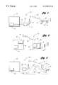
- FIG. 1is a broadband communication system utilizing a first LMDS architecture of the present invention
- FIG. 2is a broadband communication system utilizing a second LMDS architecture of the present invention.
- FIG. 3is a broadband communication system utilizing a third LMDS architecture of the present invention, and further illustrates LMDS architecture supplementing an existing wireline network (shown in dashed line).
- a broadband communication system of the present inventionis generally indicated at 10 .
- System 10includes a central office 12 with a connection 14 to a high speed network (not shown).
- a suitable high speed networkis an asynchronous transfer mode (ATM) network.
- Connection 14is connected by a fiber 6 to a local multipoint distribution system (LMDS) hub 18 .
- Fiber 16is used to send a signal from central office 12 to LMDS hub 18 .
- the signalmay be routed along line 20 to a 22 , which in turn transmits the signal.
- line 20is coaxial cable.
- Tower antenna 22transmits the signal which is received by a local multipoint distribution system (LMDS) remote terminal 24 .
- LMDSlocal multipoint distribution system
- LMDS remote terminal 24 and tower antenna 22communicate in preferably two-way communication as indicated by double arrow 26 .
- Remote terminal 24operates to separate the received signal into a plurality of customer signals corresponding to a plurality of customers. Each customer is served by a separate digital signal line 28 , 30 , 32 .
- Customers signal lines 28 , 30 , 32connect to customer sites 34 , 36 , 38 , respectively.
- digital signal lines 28 , 30 , 32may take a variety of forms.
- the digital signal lines of this LMDS architecture and other LMDS architectures of the present inventionare xDSL (of which VDSL is a suitable category thereof), and DS lines such as DS 0 and DS 1 lines.
- System 50includes a central office 52 with a connection 54 to a high speed network (not shown), and including an LMDS hub 56 .
- LMDS hub 56is connected to an antenna 58 .
- Antenna 58is operative to transmit a signal.
- Antenna 58transmits the signal for reception by receiving antenna 60 at LMDS remote terminal 62 .
- system 50is configured for two-way communication as indicated by double arrow 64 .
- Remote terminal 62is shown in greater detail than remote terminal 24 (FIG. 1 ); but, of course, it is to be appreciated that various arrangements for the internal workings of the remote terminals are apparent to and appreciated by those skilled in the LMDS communications art.
- Remote terminal 62includes an LMDS modem 66 to convert the radio frequency signal to a digital signal, and is connected to a multiplexer 68 .
- multiplexer 68may take a variety of forms, such as for example, a digital subscriber line access multiplexer (DSLAM) or a traditional demultiplexer for use with DS 0 standard two wire twisted pairs.
- DSLAMdigital subscriber line access multiplexer
- a plurality of customer digital signal lines, with separate lines indicated at 70 , 72 , 74connect to customer sites 76 , 78 , 80 , respectively.
- System 100includes a central office 102 with a connection 104 to a high speed network (not shown), with a fiber 106 connected in between central office 102 and an LMDS hub 108 .
- LMSD hub 108connects along line 110 to tower antenna 112 .
- Tower antenna 112transits the signal to LMDS remote terminal 114 which has receiving antenna 116 .
- two-way communicationis allowed as indicated by double arrow 118 .
- Remote terminal 114connects through a fiber 120 into network 122 , and eventually to an interface node 124 .
- an LMDS architecture of the present inventionmay be utilized to expand the capabilities of an existing wire line network, indicated in hidden line at 126 . That is, additional bandwidth demand may arise at network interface node 124 , requiring the system provider to find a way to increase total bandwidth inflow to node 124 .
- an LMDS architecturemay be utilized as an alternative to the expensive laying of fiber by instead providing an LMDS link from a new LMDS hub. Still further, in accordance with the present invention, LMDS architectures may be utilized to overcome obstacles that would make the laying of fiber difficult or very costly.
Landscapes
- Engineering & Computer Science (AREA)
- Computer Networks & Wireless Communication (AREA)
- Signal Processing (AREA)
- Mobile Radio Communication Systems (AREA)
Abstract
Description
Claims (17)
Priority Applications (2)
| Application Number | Priority Date | Filing Date | Title |
|---|---|---|---|
| US09/266,651US6580728B1 (en) | 1999-03-11 | 1999-03-11 | Local multi-point-distribution system architectures |
| US10/427,431US6876673B2 (en) | 1999-03-11 | 2003-04-29 | Local multi-point distribution system architectures |
Applications Claiming Priority (1)
| Application Number | Priority Date | Filing Date | Title |
|---|---|---|---|
| US09/266,651US6580728B1 (en) | 1999-03-11 | 1999-03-11 | Local multi-point-distribution system architectures |
Related Child Applications (1)
| Application Number | Title | Priority Date | Filing Date |
|---|---|---|---|
| US10/427,431ContinuationUS6876673B2 (en) | 1999-03-11 | 2003-04-29 | Local multi-point distribution system architectures |
Publications (1)
| Publication Number | Publication Date |
|---|---|
| US6580728B1true US6580728B1 (en) | 2003-06-17 |
Family
ID=23015441
Family Applications (2)
| Application Number | Title | Priority Date | Filing Date |
|---|---|---|---|
| US09/266,651Expired - LifetimeUS6580728B1 (en) | 1999-03-11 | 1999-03-11 | Local multi-point-distribution system architectures |
| US10/427,431Expired - LifetimeUS6876673B2 (en) | 1999-03-11 | 2003-04-29 | Local multi-point distribution system architectures |
Family Applications After (1)
| Application Number | Title | Priority Date | Filing Date |
|---|---|---|---|
| US10/427,431Expired - LifetimeUS6876673B2 (en) | 1999-03-11 | 2003-04-29 | Local multi-point distribution system architectures |
Country Status (1)
| Country | Link |
|---|---|
| US (2) | US6580728B1 (en) |
Cited By (13)
| Publication number | Priority date | Publication date | Assignee | Title |
|---|---|---|---|---|
| US20020128009A1 (en)* | 2001-02-20 | 2002-09-12 | Erik Boch | Transceiver for fixed wireless access network applications |
| US20030190890A1 (en)* | 1999-03-11 | 2003-10-09 | Cook Charles I. | Local multi-point distribution system architectures |
| US6839361B2 (en)* | 1998-11-02 | 2005-01-04 | Cisco Technology, Inc. | Local multipoint distribution service base station apparatus |
| US20080042535A1 (en)* | 2006-08-21 | 2008-02-21 | Afl Telecommunications Llc. | Novel design for a fiber distribution cabinet |
| US20080280569A1 (en)* | 2004-05-06 | 2008-11-13 | Serconet Ltd. | System and Method for Carrying a Wireless Based Signal Over Wiring |
| US7633966B2 (en) | 2000-04-19 | 2009-12-15 | Mosaid Technologies Incorporated | Network combining wired and non-wired segments |
| US7813451B2 (en) | 2006-01-11 | 2010-10-12 | Mobileaccess Networks Ltd. | Apparatus and method for frequency shifting of a wireless signal and systems using frequency shifting |
| US8175649B2 (en) | 2008-06-20 | 2012-05-08 | Corning Mobileaccess Ltd | Method and system for real time control of an active antenna over a distributed antenna system |
| US8594133B2 (en) | 2007-10-22 | 2013-11-26 | Corning Mobileaccess Ltd. | Communication system using low bandwidth wires |
| US8897215B2 (en) | 2009-02-08 | 2014-11-25 | Corning Optical Communications Wireless Ltd | Communication system using cables carrying ethernet signals |
| US9184960B1 (en) | 2014-09-25 | 2015-11-10 | Corning Optical Communications Wireless Ltd | Frequency shifting a communications signal(s) in a multi-frequency distributed antenna system (DAS) to avoid or reduce frequency interference |
| US9338823B2 (en) | 2012-03-23 | 2016-05-10 | Corning Optical Communications Wireless Ltd | Radio-frequency integrated circuit (RFIC) chip(s) for providing distributed antenna system functionalities, and related components, systems, and methods |
| US10986164B2 (en) | 2004-01-13 | 2021-04-20 | May Patents Ltd. | Information device |
Citations (1)
| Publication number | Priority date | Publication date | Assignee | Title |
|---|---|---|---|---|
| US6047177A (en)* | 1996-01-26 | 2000-04-04 | Telia Ab | Method, device, and system for radio communication at short distances |
Family Cites Families (6)
| Publication number | Priority date | Publication date | Assignee | Title |
|---|---|---|---|---|
| US5867485A (en) | 1996-06-14 | 1999-02-02 | Bellsouth Corporation | Low power microcellular wireless drop interactive network |
| DE19632791B4 (en) | 1996-08-15 | 2009-06-25 | Deutsche Telekom Ag | Method and system for broadcasting |
| US6243577B1 (en) | 1997-08-15 | 2001-06-05 | Hewlett-Packard Corporation | Frequency translation to local multi-point distribution system for personal communications services |
| US6115372A (en) | 1998-02-04 | 2000-09-05 | Newcom Technologies, Inc. | Synchronous packet switching |
| US6580728B1 (en)* | 1999-03-11 | 2003-06-17 | Qwest Communications International Inc. | Local multi-point-distribution system architectures |
| US6240274B1 (en) | 1999-04-21 | 2001-05-29 | Hrl Laboratories, Llc | High-speed broadband wireless communication system architecture |
- 1999
- 1999-03-11USUS09/266,651patent/US6580728B1/ennot_activeExpired - Lifetime
- 2003
- 2003-04-29USUS10/427,431patent/US6876673B2/ennot_activeExpired - Lifetime
Patent Citations (1)
| Publication number | Priority date | Publication date | Assignee | Title |
|---|---|---|---|---|
| US6047177A (en)* | 1996-01-26 | 2000-04-04 | Telia Ab | Method, device, and system for radio communication at short distances |
Cited By (35)
| Publication number | Priority date | Publication date | Assignee | Title |
|---|---|---|---|---|
| US6839361B2 (en)* | 1998-11-02 | 2005-01-04 | Cisco Technology, Inc. | Local multipoint distribution service base station apparatus |
| US6876673B2 (en)* | 1999-03-11 | 2005-04-05 | Qwest Communications, International Inc. | Local multi-point distribution system architectures |
| US20030190890A1 (en)* | 1999-03-11 | 2003-10-09 | Cook Charles I. | Local multi-point distribution system architectures |
| US8289991B2 (en) | 2000-04-19 | 2012-10-16 | Mosaid Technologies Incorporated | Network combining wired and non-wired segments |
| US8873586B2 (en) | 2000-04-19 | 2014-10-28 | Conversant Intellectual Property Management Incorporated | Network combining wired and non-wired segments |
| US8873575B2 (en) | 2000-04-19 | 2014-10-28 | Conversant Intellectual Property Management Incorporated | Network combining wired and non-wired segments |
| US7633966B2 (en) | 2000-04-19 | 2009-12-15 | Mosaid Technologies Incorporated | Network combining wired and non-wired segments |
| US7636373B2 (en) | 2000-04-19 | 2009-12-22 | Mosaid Technologies Incorporated | Network combining wired and non-wired segments |
| US7715441B2 (en) | 2000-04-19 | 2010-05-11 | Mosaid Technologies Incorporated | Network combining wired and non-wired segments |
| US8867506B2 (en) | 2000-04-19 | 2014-10-21 | Conversant Intellectual Property Management Incorporated | Network combining wired and non-wired segments |
| US7876767B2 (en) | 2000-04-19 | 2011-01-25 | Mosaid Technologies Incorporated | Network combining wired and non-wired segments |
| US7933297B2 (en) | 2000-04-19 | 2011-04-26 | Mosaid Technologies Incorporated | Network combining wired and non-wired segments |
| US8848725B2 (en) | 2000-04-19 | 2014-09-30 | Conversant Intellectual Property Management Incorporated | Network combining wired and non-wired segments |
| US8982904B2 (en) | 2000-04-19 | 2015-03-17 | Conversant Intellectual Property Management Inc. | Network combining wired and non-wired segments |
| US8982903B2 (en) | 2000-04-19 | 2015-03-17 | Conversant Intellectual Property Management Inc. | Network combining wired and non-wired segments |
| US20020128009A1 (en)* | 2001-02-20 | 2002-09-12 | Erik Boch | Transceiver for fixed wireless access network applications |
| US10986164B2 (en) | 2004-01-13 | 2021-04-20 | May Patents Ltd. | Information device |
| US8325693B2 (en) | 2004-05-06 | 2012-12-04 | Corning Mobileaccess Ltd | System and method for carrying a wireless based signal over wiring |
| US8325759B2 (en) | 2004-05-06 | 2012-12-04 | Corning Mobileaccess Ltd | System and method for carrying a wireless based signal over wiring |
| US20080280569A1 (en)* | 2004-05-06 | 2008-11-13 | Serconet Ltd. | System and Method for Carrying a Wireless Based Signal Over Wiring |
| US8184681B2 (en) | 2006-01-11 | 2012-05-22 | Corning Mobileaccess Ltd | Apparatus and method for frequency shifting of a wireless signal and systems using frequency shifting |
| US20110206088A1 (en)* | 2006-01-11 | 2011-08-25 | Mobileaccess Networks Ltd. | Apparatus and method for frequency shifting of a wireless signal and systems using frequency shifting |
| US7813451B2 (en) | 2006-01-11 | 2010-10-12 | Mobileaccess Networks Ltd. | Apparatus and method for frequency shifting of a wireless signal and systems using frequency shifting |
| US8322803B2 (en) | 2006-08-21 | 2012-12-04 | Afl Telecommunications, Llc | Fiber distribution cabinet |
| US20080042535A1 (en)* | 2006-08-21 | 2008-02-21 | Afl Telecommunications Llc. | Novel design for a fiber distribution cabinet |
| US8594133B2 (en) | 2007-10-22 | 2013-11-26 | Corning Mobileaccess Ltd. | Communication system using low bandwidth wires |
| US9813229B2 (en) | 2007-10-22 | 2017-11-07 | Corning Optical Communications Wireless Ltd | Communication system using low bandwidth wires |
| US9549301B2 (en) | 2007-12-17 | 2017-01-17 | Corning Optical Communications Wireless Ltd | Method and system for real time control of an active antenna over a distributed antenna system |
| US8175649B2 (en) | 2008-06-20 | 2012-05-08 | Corning Mobileaccess Ltd | Method and system for real time control of an active antenna over a distributed antenna system |
| US8897215B2 (en) | 2009-02-08 | 2014-11-25 | Corning Optical Communications Wireless Ltd | Communication system using cables carrying ethernet signals |
| US9338823B2 (en) | 2012-03-23 | 2016-05-10 | Corning Optical Communications Wireless Ltd | Radio-frequency integrated circuit (RFIC) chip(s) for providing distributed antenna system functionalities, and related components, systems, and methods |
| US9948329B2 (en) | 2012-03-23 | 2018-04-17 | Corning Optical Communications Wireless, LTD | Radio-frequency integrated circuit (RFIC) chip(s) for providing distributed antenna system functionalities, and related components, systems, and methods |
| US9184960B1 (en) | 2014-09-25 | 2015-11-10 | Corning Optical Communications Wireless Ltd | Frequency shifting a communications signal(s) in a multi-frequency distributed antenna system (DAS) to avoid or reduce frequency interference |
| US9253003B1 (en) | 2014-09-25 | 2016-02-02 | Corning Optical Communications Wireless Ltd | Frequency shifting a communications signal(S) in a multi-frequency distributed antenna system (DAS) to avoid or reduce frequency interference |
| US9515855B2 (en) | 2014-09-25 | 2016-12-06 | Corning Optical Communications Wireless Ltd | Frequency shifting a communications signal(s) in a multi-frequency distributed antenna system (DAS) to avoid or reduce frequency interference |
Also Published As
| Publication number | Publication date |
|---|---|
| US20030190890A1 (en) | 2003-10-09 |
| US6876673B2 (en) | 2005-04-05 |
Similar Documents
| Publication | Publication Date | Title |
|---|---|---|
| US20040054425A1 (en) | Method and apparatus for information conveyance and distribution | |
| US6580728B1 (en) | Local multi-point-distribution system architectures | |
| US7796890B1 (en) | Hybrid PON/surface wave terrestrial access | |
| CN1638504B (en) | Radio base station with multiple radio frequency heads | |
| EP0421602B1 (en) | Hybrid network | |
| US20100189439A1 (en) | Optical fiber distributed wireless personal area network | |
| US6560213B1 (en) | Wideband wireless access local loop based on millimeter wave technology | |
| US6725059B1 (en) | System and method for improving communications between a digital loop carrier and a central office | |
| US20080186881A1 (en) | System For Distributing Radio Signal | |
| Gray | A broadband wireless access system at 28 GHz | |
| US6678259B1 (en) | System and method for line of sight path communication | |
| KR20040101996A (en) | System for and method of implementing wireless neighborhood area networks | |
| CN111200825B (en) | 5G network indoor coverage system based on HFC network | |
| KR100312215B1 (en) | An apparatus for improved network operations | |
| EP1190514B1 (en) | Broadband architecture using existing twisted pair | |
| KR20010112498A (en) | Television receive, Internet conneting and inner area LAN system | |
| JP3795768B2 (en) | Network system | |
| US20010015967A1 (en) | Wireless LAN system | |
| US7043197B2 (en) | Telecommunication system for the bidirectional transmission of data and voice signals | |
| KR19990046136A (en) | Internet Subscriber Network | |
| KR101052175B1 (en) | Apparatus and method for mobile communication signal relay using CYPEN reserve circuit | |
| US20020101914A1 (en) | Extended reach VDSL | |
| US7593391B2 (en) | System and method for high speed distributed cable broadband system | |
| US20030179286A1 (en) | System for distributing television programmes and for carrying out communications services, as well as central unit of a distribution system, communications terminal, plug-in board for a computer and connection unit | |
| Webb | A comparison of wireless local loop with competing access technologies |
Legal Events
| Date | Code | Title | Description |
|---|---|---|---|
| AS | Assignment | Owner name:U S WEST, INC., COLORADO Free format text:ASSIGNMENT OF ASSIGNORS INTEREST;ASSIGNORS:COOK, CHARLES I.;JEVREMOVIC, VLADAN;REEL/FRAME:009816/0915;SIGNING DATES FROM 19990216 TO 19990303 | |
| AS | Assignment | Owner name:QWEST COMMUNICATIONS INTERNATIONAL INC., COLORADO Free format text:MERGER;ASSIGNOR:U S WEST, INC.;REEL/FRAME:010814/0339 Effective date:20000630 | |
| STCF | Information on status: patent grant | Free format text:PATENTED CASE | |
| FPAY | Fee payment | Year of fee payment:4 | |
| FPAY | Fee payment | Year of fee payment:8 | |
| REMI | Maintenance fee reminder mailed | ||
| FPAY | Fee payment | Year of fee payment:12 | |
| SULP | Surcharge for late payment | Year of fee payment:11 | |
| AS | Assignment | Owner name:BANK OF AMERICA, N.A., AS COLLATERAL AGENT, NORTH CAROLINA Free format text:SECURITY INTEREST;ASSIGNOR:QWEST COMMUNICATIONS INTERNATIONAL INC.;REEL/FRAME:044652/0829 Effective date:20171101 Owner name:BANK OF AMERICA, N.A., AS COLLATERAL AGENT, NORTH Free format text:SECURITY INTEREST;ASSIGNOR:QWEST COMMUNICATIONS INTERNATIONAL INC.;REEL/FRAME:044652/0829 Effective date:20171101 |