US6579291B1 - Devices and methods for the treatment of spinal disorders - Google Patents
Devices and methods for the treatment of spinal disordersDownload PDFInfo
- Publication number
- US6579291B1 US6579291B1US09/685,401US68540100AUS6579291B1US 6579291 B1US6579291 B1US 6579291B1US 68540100 AUS68540100 AUS 68540100AUS 6579291 B1US6579291 B1US 6579291B1
- Authority
- US
- United States
- Prior art keywords
- annulus
- disc
- treating
- elongate member
- insertion tool
- Prior art date
- Legal status (The legal status is an assumption and is not a legal conclusion. Google has not performed a legal analysis and makes no representation as to the accuracy of the status listed.)
- Expired - Lifetime, expires
Links
Images


Classifications
- A—HUMAN NECESSITIES
- A61—MEDICAL OR VETERINARY SCIENCE; HYGIENE
- A61B—DIAGNOSIS; SURGERY; IDENTIFICATION
- A61B17/00—Surgical instruments, devices or methods
- A61B17/56—Surgical instruments or methods for treatment of bones or joints; Devices specially adapted therefor
- A61B17/58—Surgical instruments or methods for treatment of bones or joints; Devices specially adapted therefor for osteosynthesis, e.g. bone plates, screws or setting implements
- A61B17/68—Internal fixation devices, including fasteners and spinal fixators, even if a part thereof projects from the skin
- A61B17/70—Spinal positioners or stabilisers, e.g. stabilisers comprising fluid filler in an implant
- A—HUMAN NECESSITIES
- A61—MEDICAL OR VETERINARY SCIENCE; HYGIENE
- A61F—FILTERS IMPLANTABLE INTO BLOOD VESSELS; PROSTHESES; DEVICES PROVIDING PATENCY TO, OR PREVENTING COLLAPSING OF, TUBULAR STRUCTURES OF THE BODY, e.g. STENTS; ORTHOPAEDIC, NURSING OR CONTRACEPTIVE DEVICES; FOMENTATION; TREATMENT OR PROTECTION OF EYES OR EARS; BANDAGES, DRESSINGS OR ABSORBENT PADS; FIRST-AID KITS
- A61F2/00—Filters implantable into blood vessels; Prostheses, i.e. artificial substitutes or replacements for parts of the body; Appliances for connecting them with the body; Devices providing patency to, or preventing collapsing of, tubular structures of the body, e.g. stents
- A61F2/02—Prostheses implantable into the body
- A61F2/30—Joints
- A61F2/44—Joints for the spine, e.g. vertebrae, spinal discs
- A61F2/442—Intervertebral or spinal discs, e.g. resilient
- A61F2002/4435—Support means or repair of the natural disc wall, i.e. annulus, e.g. using plates, membranes or meshes
Definitions
- the present inventiongenerally relates to spinal implants. Specifically, the present invention relates to implantable devices and methods for the treatment of spinal disorders associated with the intervertebral disc.
- LBPlower back pain
- Some forms of back painare muscular in nature and may be simply treated by rest, posture adjustments and painkillers.
- some forms of lower back pain (LBP)are very common and may be caused by unusual exertion or injury. Unusual exertion such has heavy lifting or strenuous exercise may result in back strain such as a pulled muscle, sprained muscle, sprained ligament, muscle spasm, or a combination thereof. An injury caused by falling down or a blow to the back may cause bruising.
- LBPlower back pain
- LBPlower back pain
- Unusual exertionsuch has heavy lifting or strenuous exercise may result in back strain such as a pulled muscle, sprained muscle, sprained ligament, muscle spasm, or a combination thereof.
- An injury caused by falling down or a blow to the backmay cause bruising.
- These forms of back painare typically non-chronic and may be self-treated and cured in a few days or weeks.
- non-chronic back painmay be treated by improvements in physical condition, posture and/or work conditions. For example, being pregnant, obese or otherwise significantly overweight may cause LBP. A mattress that does not provide adequate support may cause back pain in the morning. Working in an environment lacking good ergonomic design may also cause back pain. In these instances, the back pain may be cured by eliminating the culprit cause. Whether it is excess body weight, a bad mattress, or a bad office chair, these forms of back pain are readily treated.
- disc related paina chronic back pain referred to as disc related pain.
- the exact origin of disc related painis often uncertain, and although some episodes of disc related pain may be eased with conservative treatments such as bed-rest and physical therapy, future episodes of disc related pain are likely to occur periodically.
- DDDdegenerative disc disease
- a commonly suspected source of disc related painis physical impingement of the nerve roots emanating from the spinal cord.
- Such nerve root impingementmay have a number of different underlying causes, but nerve root impingement generally results from either a disc protrusion or a narrowing of the intervertebral foramina (which surround the nerve roots).
- the annulus fibrosus of the discmay tear, forming one or more fissures (also referred to as fractures). Such fissures may progress to larger tears which allow the gelatinous material of the nucleus pulposus to flow out of the nucleus and into the outer aspects of the annulus. The flow of the nucleus pulposus to the outer aspects of the annulus may cause a localized bulge.
- the nerve rootsWhen bulging of the annulus occurs in the posterior portions of the disc, the nerve roots may be directly and physically impinged by the bulge. In more extreme or progressed instances of annular tears, the nuclear material may escape, additionally causing chemical irritation of the nerve roots.
- the conditionmay be referred to as a disc stenosis, a disc bulge, a herniated disc, a prolapsed disc, a ruptured disc, or, if the protrusion separates from the disc, a sequestered disc.
- Dehydration and progressive degeneration of the discalso leads to thinning of the disc.
- the intervertebral foraminaebecome narrow. Because the nerve roots pass through the intervertebral foraminae, such narrowing may mechanically entrap the nerve roots. This entrapment can cause direct mechanical compression, or may tether the roots, allowing them to be excessively tensioned during body movements.
- Nerve root impingementmost often occurs in the lumbar region of the spinal column since the lumbar discs bear significant vertical loads relative to discs in other regions of the spine.
- disc protrusions in the lumbar regiontypically occur posteriorly because the annulus fibrosus is radially thinner on the posterior side than on the anterior side and because normal posture places more compression on the posterior side.
- Posterior protrusionsare particularly problematic since the nerve roots are posteriorly positioned relative to the intervertebral discs.
- Lower back pain due to nerve root irritationnot only results in strong pain in the region of the back adjacent the disc, but may also cause sciatica, or pain radiating down one or both legs. Such pain may also be aggravated by such subtle movements as coughing, bending over, or remaining in a sitting position for an extended period of time.
- fissuresAnother suspected source of disc related back pain is damage and irritation to the small nerve endings which lie in close proximity to or just within the outer aspects of the annulus of the discs.
- the annulus fibrosusmay be damaged forming fissures. While these fissures can lead to pain via the mechanisms described above, they may also lead to pain emanating from the small nerve endings in or near the annulus, due to mechanical or chemical irritation at the sites of the fissures.
- the fissuresmay continue to irritate the small nerve endings, as their presence cause the disc to become structurally weaker, allowing for more localized straining around the fissures. This results in more relative motion of edges of the fissures, increasing mechanical irritation. Because it is believed that these fissures have only limited healing ability once formed, such irritation may only become progressively worse.
- a common treatment for a disc protrusionis discectomy, a procedure wherein the protruding portion of the disc is surgically removed.
- discectomy procedureshave an inherent risk since the portion of the disc to be removed is immediately adjacent the nerve root and any damage to the nerve root is clearly undesirable.
- discectomy proceduresare not always successful long term because scar tissue may form and/or additional disc material may subsequently protrude from the disc space as the disc deteriorates further.
- the recurrence of a disc protrusionmay necessitate a repeat discectomy procedure, along with its inherent clinical risks and less than perfect long term success rate.
- a discectomy procedureat least as a stand-alone procedure, is clearly not an optimal solution.
- Discectomyis also not a viable solution for DDD when no disc protrusion is involved.
- DDDcauses the entire disc to degenerate, narrowing of the intervertebral space, and shifting of the load to the facet joints. If the facet joints carry a substantial load, the joints may degrade over time and be a different cause of back pain.
- the narrowed disc spacecan result in the intervertebral foramina surrounding the nerve roots to directly impinge on one or more nerve roots. Such nerve impingement is very painful and cannot be corrected by a discectomy procedure.
- discectomydoes not address pain caused by the fissures which may cause direct mechanical irritation to the small nerve endings near or just within the outer aspect of the annulus of a damaged disc.
- spinal fusionparticularly with the assistance of interbody fusion cages, has become a preferred secondary procedure, and in some instances, a preferred primary procedure.
- Spinal fusioninvolves permanently fusing or fixing adjacent vertebrae.
- Hardware in the form of bars, plates, screws and cagesmay be utilized in combination with bone graft material to fuse adjacent vertebrae.
- Spinal fusionmay be performed as a stand-alone procedure or may be performed in combination with a discectomy procedure.
- spinal fusion proceduresare invasive to the disc, risk nerve damage and, depending on the procedural approach, either technically complicated (endoscopic anterior approach), invasive to the bowel (surgical anterior approach), or invasive to the musculature of the back (surgical posterior approach).
- Another procedure that has been less than clinically successfulis total disc replacement with a prosthetic disc.
- This procedureis also very invasive to the disc and, depending on the procedural approach, either invasive to the bowel (surgical anterior approach) or invasive to the musculature of the back (surgical posterior approach).
- the proceduremay actually complicate matters by creating instability in the spine, and the long term mechanical reliability of prosthetic discs has yet to be demonstrated.
- the present inventionaddresses this need by providing improved devices and methods for the treatment of spinal disorders.
- the improved devices and methods of the present inventionspecifically address disc related pain, particularly in the lumbar region, but may have other significant applications not specifically mentioned herein.
- the present inventionis discussed in detail with reference to the treatment of damaged discs in the lumbar region of the adult human spinal column.
- the improved devices and methods of the present inventionreduce if not eliminate back pain while maintaining near normal anatomical motion.
- the present inventionprovides disc reinforcement devices to reinforce a damaged disc, while permitting relative movement of the vertebrae adjacent the damaged disc.
- the devices of the present inventionare particularly well suited for minimally invasive methods of implantation.
- the reinforcement devices of the present inventionprovide three distinct functions. Firstly, the reinforcement devices mechanically stabilize and strengthen the disc to minimize if not eliminate chronic irritation of nerve roots and nerves around the periphery of the disc annulus. Secondly, the reinforcement devices radially and/or circumferentially compress the disc to close fissures, fractures and tears, thereby preventing the ingress of nerves and potentially facilitating healing. Thirdly, the reinforcement devices may be used to stabilize the posterior disc after a discectomy procedure in order to reduce the need for re-operation.
- the present inventionprovides disc reinforcement therapy (DRT) in which a reinforcement member is implanted in the annulus of an intervertebral disc.
- DVTdisc reinforcement therapy
- the implantation methodmay be performed by a percutaneous procedure or by a minimally invasive surgical procedure.
- the present inventionprovides a number or tools to facilitate percutaneous implantation.
- One or more reinforcement membersmay be implanted, for example, posteriorly, anteriorly, and/or laterally, and may be oriented circumferentially or radially. As such, the reinforcement members may be used to stabilize the annulus and/or compresses a portion of the annulus so as to reduce a bulge and/or close a fissure.
- the reinforcement membermay be sized to pass through a trocar and may have a tubular cross-section to facilitate advancement over a stylet.
- the reinforcement memberpreferably includes a body portion sized to fit in the annulus and an anchor for engaging the annulus and limiting relative movement therebetween.
- the anchormay be disposed only at the end portions of the body, or may extend over the entire length of the body.
- the anchormay comprise threads which may have a variable pitch to facilitate compression of the annulus during implantation.
- the reinforcement membermay incorporate chemical and/or biological agents.
- the reinforcement membermay comprise a biocompatible metal such as stainless steel or a super elastic (nickel titanium) alloy.
- the reinforcement membermay comprise a polymer or a reinforced polymeric structure.
- the reinforcement membermay comprise a bioabsorbable material.
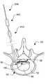
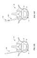
- FIGS. 1A and 1Billustrate left lateral and posterior views, respectively, of a portion of the adult human vertebral (spinal) column;
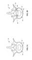
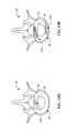
- FIGS. 2A and 2Billustrate superior (top) views of a healthy disc and a degenerated disc, respectively, and an adjacent vertebral body;
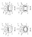
- FIGS. 3A-3Dschematically illustrate superior (top) views of reinforcement members disposed in degenerated discs
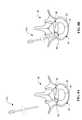
- FIGS. 4A-4Gschematically illustrate various features that may be incorporated into a straight or curved reinforcement member in accordance with an embodiment of the present invention
- FIGS. 5A-5Cschematically illustrate a circumferential reinforcement member in accordance with an embodiment of the present invention
- FIGS. 6A-6Hschematically illustrate components of a reinforcement member in accordance with an embodiment of the present invention
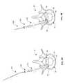
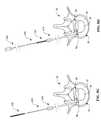
- FIGS. 7A-7Fillustrate tools of the present invention for implanting the reinforcement members shown in FIGS. 3A and 3B in accordance with the method illustrated in FIGS. 8A-8L;
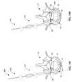
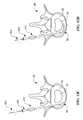
- FIGS. 8A-8Lillustrate a method for implanting the reinforcement members shown in FIGS. 3A and 3B in accordance with an embodiment of the present invention
- FIGS. 9A-9Cillustrate tools of the present invention for implanting the reinforcement member shown in FIG. 3C in accordance with the method illustrated in FIGS. 10A-10H;
- FIGS. 10A-10Hillustrate a method for implanting the reinforcement member shown in FIG. 3C in accordance with an embodiment of the present invention
- FIGS. 11A-11Hillustrate a method for implanting the reinforcement member shown in FIG. 3D in accordance with an embodiment of the present invention
- FIGS. 12A-12Jillustrate steps for implanting a self-expanding reinforcement member
- FIGS. 12K-12Lillustrate steps for implanting an inflatable reinforcement member
- FIGS. 12M-12Rillustrate steps for implanting a reinforcement bar.
- the lower portion of an adult human vertebral column 10is illustrated in left lateral and posterior views, respectively.
- the upper portion of the vertebral column 10includes the thoracic region and the cervical region, which are not shown for purposes of simplified illustration only.
- the lower portion of the vertebral column 10includes the lumbar region 12 , the sacrum 14 and the coccyx 16 .
- the sacrum 14 and the coccyx 16are sometimes collectively referred to as the pelvic curvature.
- the vertebral column 10includes an axis of curvature 60 which generally forms a double-S shape when viewed laterally.
- the vertebral column 10also includes a median plane 70 which is a sagittal plane bisecting the vertebral column 10 into symmetrical left lateral and right lateral portions. In posterior views, the median plane 70 appears as a line.
- the lumbar region 12 of the vertebral column 10includes five (5) vertebrae 20 (labeled L 1 , L 2 , L 3 , L 4 and L 5 ) separated by intervertebral discs 50 .
- the sacrum 14which includes five (5) fused vertebrae 30 (superior vertebra 30 labeled S 1 ), is separated by a single disc 50 from the coccyx 16 , which includes four (4) fused vertebrae 40 .
- the intervertebral discs 50may be referenced by their respective adjacent vertebrae.
- the disc 50 between the L 4 and L 5 lumbar vertebrae 20may be referred to as the L 4 L 5 disc.
- the disc 50 between the L 5 lumbar vertebra 20 and the S 1 sacral vertebra 30may be referred to as the L 5 S 1 disc.
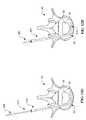
- each vertebra 20 / 30 / 40is a unique and irregular bone structure
- the vertebrae 20 of the lumbar region 12(in addition to the thoracic and cervical regions) have common structures.
- Each vertebra 20 of the lumbar region 12generally includes a body portion 21 and a vertebral arch portion 22 / 23 which encloses the vertebral foramen (not visible) in which the spinal cord is disposed.
- the vertebral arch 22 / 23includes two pedicles 22 and two laminae 23 .
- a spinous process 24extends posteriorly from the juncture of the two laminae 23
- two transverse processes 25extend laterally from each lamina 23 .
- Four articular processes 26 / 27extend inferiorly 26 and superiorly 27 from the laminae 23 .
- the inferior articular process 26rests in the superior articular process 27 of the adjacent vertebra to form a facet joint 28 .
- the five (5) vertebrae 30 of the sacrum 14are fused together to form a single rigid structure.
- the sacrum 14includes a median sacral crest 31 which roughly corresponds to the spinous processes of the vertebrae 30 , and two intermediate sacral crests 32 which roughly correspond to the articular processes of the vertebrae 30 .
- the sacral laminae 33are disposed between the median 31 and intermediate 32 sacral crests.
- Two lateral sacral crests 34are disposed on either side of the sacral foraminae 35 .
- the sacrum 14also includes a pair of sacral wings 36 which define auricular surfaces 39 .
- the superior (S 1 ) sacral vertebra 30includes two superior articular processes 37 which engage the inferior articular processes 26 of the L 5 lumber vertebra 20 to form a facet joint, and the base 38 of the superior sacral vertebra S 1 is joined to the L 5 S 1 disc 50 .
- each intervertebral disc 50includes an annulus fibrosus 52 surrounding a nucleus pulposus 54 .
- the posterior annulus 52is generally thinner than the anterior annulus 52 , which may account for the higher incidence of posterior disc protrusions.
- the annulus fibrosus 52comprises about 60% of the total disc 50 cross-sectional area, and the nucleus pulposus 54 only comprises about 40% of the total disc 50 cross-sectional area.
- the annulus fibrosus 52comprises 40-60% organized collagen in the form of a laminated structure.
- the nucleus pulposus 54comprises 18-30% collagen in the form of a relatively homogenous gel.
- each intervertebral disc 50forms one support point and the facet joints 28 form two support points of what may be characterized as a three point support structure between adjacent vertebrae 20 .
- the facet joints 28are substantially vertical, leaving the disc 50 to carry the vast majority of the load.
- the nucleus 54bears the majority of the load. This belief is based on the theory that the disc 50 behaves much like a balloon or tire, wherein the annulus 52 merely serves to contain the pressurized nucleus 54 , and the nucleus 54 bears all the load.
- annulus fibrosus 52comprises 60% of the total disc 50 cross-sectional area and is made of 40-60% organized collagen in the form of a laminated structure.
- nucleus pulposus 54only comprises 40% of the total disc 50 cross-section and is made of 18-30% collagen in the form of a relatively homogenous gel.
- annulus fibrosus 52is the primary load bearing portion of the disc 50 .
- the intervertebral discs 50become progressively dehydrated and malnourished with age.
- the discbegins to degenerate.
- the annulus fibrosus of the discmay tear, forming one or more radial fissures 56 or circumferential fissures 58 , which may progress to larger tears. Larger tears may allow the gelatinous material of the nucleus pulposus 54 to flow out of the nucleus and into the outer aspects of the annulus 52 .
- the flow of the nucleus pulposus 54 to the outer aspects of the annulus 52may cause a localized bulge 60 .
- a posterior bulge 60may result in direct impingement of a nerve root (not shown). Nuclear material that escapes through an advanced tear may cause further mechanical irritation and additionally cause chemical irritation of a nerve root.
- a nerve rootmay also be compressed or tethered by a narrowing of the intervertebral foraminae, resulting from a loss in disc height caused by sustained degeneration of the disc 50 .
- Small nerve endings (not shown) in or near the perimeter of the annulus 52may also be mechanically or chemically irritated at the sites of the fissures 56 / 58 . In all cases, degeneration of the disc eventually leads to disc related pain of some origin.
- FIGS. 3A-3Dschematically illustrate reinforcement members 100 / 200 / 300 implanted in a degenerated disc 50 .
- the reinforcement members 100 / 200 / 300mechanically stabilize and strengthen the disc 50 to minimize if not eliminate chronic irritation of nerve roots and nerves around the periphery of the disc annulus 52 .
- the reinforcement members 100 / 200 / 300also radially and/or circumferentially compress the disc 50 to close fissures 56 / 58 , thereby preventing the ingress of nerves and potentially facilitating healing.
- the reinforcement members 100 / 200 / 300may further be used to stabilize the posterior portion of the disc 50 after a discectomy procedure in order to reduce the need for re-operation.
- FIGS. 3A-3Dshow examples of where the reinforcement members 100 / 200 / 300 may be implanted in the annulus 52 .
- the reinforcement members 100 / 200 / 300may be implanted in any portion of the annulus 52 including, without limitation, the posterior, anterior or lateral portions thereof. Because most disc related pain is associated with damage to the posterior portion of the disc 50 , the reinforcement members 100 / 200 / 300 preferably provide support to the posterior portion of the annulus 52 and establish anchor points in the lateral and anterior portions of the annulus 52 .
- the reinforcement members 100 / 200 / 300may be used individually as shown in FIGS. 3A, 3 C and 3 D; or in combination as shown in FIG. 3 B. Although not shown, any combination of the different types of reinforcement members 100 / 200 / 300 may be utilized.
- the reinforcement members 100 / 200 / 300may be oriented generally parallel to the periphery of the annulus 52 (e.g., reinforcement members 100 A, 100 C, 200 , 300 ), generally radial to the annulus 52 (e.g., reinforcement member 100 B), or any other orientation suitable for stabilizing and/or compressing the desired portion(s) of the annulus 52 .
- the closer the reinforcement members 100 / 200 / 300 are to the periphery of the annulus 52the greater the amount of support and stabilization provided to the disc 50 .
- the reinforcement members 100 / 200 / 300preferably have a curvature conforming to the periphery of the annulus 52 such that they may be implanted as close to the periphery of the annulus 52 as possible.
- the reinforcement members 100 / 200 / 300may have such a curvature in the relaxed (zero stress) state, or the curvature may be imparted by the insertion path or defined by the insertion tools used.
- the reinforcement members 100 / 200 / 300may extend across and close fissures 56 / 58 as shown, or any other portion of the annulus 52 to provide compression and stabilization of the disc 50 . Although not shown, the reinforcement members 100 / 200 / 300 may extend across or into the nucleus 54 . In such a case, it is preferred that the reinforcement members 100 / 200 / 300 do not extend outside the periphery of the annulus 52 in order to reduce the probability of nuclear material escaping from the outer aspects of the annulus 52 .
- the reinforcement members 100 / 200 / 300are sized to fit within the annulus 52 of a human disc 50 .
- the collective diameter and length of the reinforcement members 100 / 200 / 300 implantedpreferably does not exceed the height and circumference/diameter, respectively, of the annulus 52 , depending on the number and orientation of the reinforcement members 100 / 200 / 300 implanted.
- the reinforcement members 100 / 200 / 300may be made of a biocompatible material or coated with a biocompatible material. Suitable structural materials for the reinforcement members 100 / 200 / 300 include stainless steel and super elastic alloys such as nickel titanium.
- All or a portion of the reinforcement members 100 / 200 / 300may be made of biodegradable or bioabsorbable material such as resorbable collagen, LPLA (poly(1-lactide)), DLPLA (poly(dl-lactide)), LPLA-DLPLA, PGA (polyglycolide), PGA-LPLA or PGA-DLPLA.
- LPLApoly(1-lactide)
- DLPLApoly(dl-lactide)
- LPLA-DLPLALPLA-DLPLA
- PGApolyglycolide
- Other metals, alloys, polymers, and composites having suitable tensile, compression and fatigue strength and elasticitymay also be used.
- the reinforcement members 100 / 200 / 300may further include growth factors to facilitate healing, agents which render nuclear matter inert or otherwise reduce chemical irritation thereof, and/or anesthetic agents to reduce nerve signal transmission (i.e., pain).
- various visualization techniquesmay be used to facilitate implantation of the reinforcement members 100 / 200 / 300 .
- real time CT scanningreal time MR imaging, or a combination of preoperative CT or MR images superimposed onto a real time device tracking images
- STEALTHTMavailable from Sofamor Danek.
- FIGS. 4A-4Gillustrate various embodiments of the reinforcement member 100 in accordance with the present invention.
- the embodiments of FIGS. 4A-4Gillustrate various features which may be combined in any way to provide the desired reinforcement member 100 .
- Reinforcement member 100may be sized and oriented as shown and discussed with reference to FIGS. 3A and 3B.
- Reinforcement member 100includes a body portion 110 and an anchor 120 .
- the anchor 120serves to immobilize or limit movement of the reinforcement member 100 relative to the annulus 52 .
- the anchoris in the form of threads 122 disposed about the periphery of the body portion 110 , which behave like threads on a screw and engage the annulus 52 upon rotation therein.
- the proximal end of the body 110may include slots 116 as shown in FIG. 4C, which is an end view taken along line 4 C— 4 C in FIG. 4 A.
- the slots 116or any other suitable mating geometry, facilitate rotation with a driver having a mating distal end.
- the anchor 120is in the form of sloped rings 124 spaced along the length of the body portion 110 , which behave like rings on a ring-shank nail to engage the annulus 52 upon pushing therein.
- anchor 120 mechanismssuch as barbs, expandable anchors, etc. may also be used.
- the anchor 120may extend the full length of the body portion 110 as shown in FIGS. 4A and 4F, or may be disposed only on proximal and distal portions of the body as shown in FIGS. 4D and 4E.
- the body portion 110may be tubular defining a lumen 112 extending therethrough as shown in FIG. 4B, which is a cross-sectional view taken along line 4 B— 4 B in FIG. 4 A.
- the lumen 112facilitates advancement of the reinforcement member 100 over a stylet to facilitate insertion into the annulus 52 , as will be discussed in greater detail hereinafter.
- the body portion 110may have a solid cross-section as shown in FIG. 4G, which is a cross-sectional view taken along line 4 G— 4 G in FIG. 4 F.
- the solid cross-section body portion 110may include a sharpened distal tip 114 as shown in FIG. 4F to facilitate insertion into the annulus 52 .
- the threads 122have a variable pitch such that the annulus is compressed as the reinforcement member 100 is rotated and advanced into the annulus 52 .
- Variable pitch threads 122as shown in FIGS. 4A, 4 D and 4 F, generally have a larger pitch at the distal end of the body 110 and a smaller pitch at the proximal end of the body 110 .
- the larger pitch distal threads 122pull the annular tissue 52 a greater distance per revolution than the smaller pitch proximal threads 122 .
- the distal threadspull the annular tissue together and the proximal threads hold the tissue in place thereby compressing the annulus 52 .
- the disc 50is mechanically stabilized and the fissures 56 / 58 are closed to facilitated healing.
- variable pitch threads 122are currently preferred.
- standard constant pitch threads 122 and tapered rings 124may achieve compression by utilizing a step-wise advancement and tension technique as will be described in more detail hereinafter.
- FIGS. 5A-5Cschematically illustrate a circumferential reinforcement member 200 , which is generally the same as reinforcement member 100 except as described herein.
- FIG. 5Bis a cross-sectional view taken along line 5 B— 5 B in FIG. 5A
- FIG. 5Cis an end view taken along line 5 C— 5 C in FIG. 5 A.
- the circumferential reinforcement member 200includes a tubular body 210 defining a lumen 212 to facilitate advancement over a stylet.
- the circumferential reinforcement member 200also includes an anchor 220 , preferably in the form of variable pitch threads 222 .
- the proximal end of the body 210the may include slots 216 or other suitable mating geometry to facilitate rotation by a driver having a mating distal end. Any of the variants of reinforcement member 100 discussed with reference to FIGS. 4A-4G may be applied to circumferential reinforcement member 200 .
- the circumferential reinforcement member 200may have a geometry (e.g., circle, ellipse, oval, etc.) corresponding to the geometry of the outer aspects of a healthy annulus 52 , or the member 200 may be naturally straight, taking on a curved shape during implantation. Because the circumferential reinforcement member 200 is implanted in the annulus 52 around the entire periphery thereof, the reinforcement member maximizes anchoring strength and provides superior stabilization around the entire disc 50 . Thus, it is preferable that the reinforcement member 200 define a closed geometry once implanted, or even have overlapping ends, but an open geometry (e.g., semi-ellipse or semi-circle) may also be employed. The size and shape of the reinforcement member 200 may be pre-selected to accommodate anatomical variations of the annulus 52 between patients. The reinforcement member may have a relaxed size that is smaller than the implanted size such that additional radial and circumferential compression is achieved.
- a geometrye.g., circle, ellipse, oval, etc.
- FIGS. 6A-6Hschematically illustrate reinforcement member 300 , including a pair of tubular pins 310 , two screws 320 and two connecting rings 330 which may be assembled as shown in FIG. 6 F.
- each of the tubular pins 310includes a shaft portion 312 , a head portion 314 and a connection mechanism 318 .
- the shaft 312is sized to fit within a hole of the connection ring 330 and the head 314 is sized larger than the same hole.
- the connection mechanism 318may comprises a threaded shaft insertable into a threaded hole as shown, or any other known mechanical releasable connection that maintains the profile of the shaft portion 312 . As seen in FIG.
- the shaft portion 312includes a lumen 313 to facilitate advancement over a stylet.
- the heads 314may each include a slot 316 as seen in FIG. 6C, which is an end view taken along line 6 C— 6 C in FIG. 6A, or other suitable geometry to mate with a distal end of a driver to facilitate rotation of the pins 310 to screw the releasable connection together.
- the screws 320include a shaft 322 , a head 324 , threads 328 and a sharpened tip 323 as seen in FIG. 6 D.
- the screws 320may comprise a wide variety of orthopedic screw designs, particularly those suitable for implantation into cartilage and other collagen-based tissues.
- the shaft 322 and threads 326are sized to fit within a hole of the connection ring 330 and the head 324 is sized larger than the same hole.
- the head 324includes slots 326 as seen in FIG. 6E, which is an end view taken along line 6 E— 6 E in FIG. 6D, or other suitable mating geometry to facilitate rotation by a driver having a mating distal end.
- connection rings 330each have first and second rings 331 / 333 defining first and second holes 332 / 334 as shown in FIG. 6 F.
- the first hole 332is sized to provide a sliding fit about the shaft 312 of the pins 310 and the second hole is sized to provide a sliding fit about the shaft 322 and threads 326 of the screws 320 .
- each of the connection rings 330also define an angle 336 between the rings 331 / 333 to accommodate the implanted arrangement as shown in FIG. 6 H.
- the tools 410 , 420 , 430 and 440may be used to implant the reinforcement members 100 discussed above.
- the toolsinclude a rigid, sharpened, hollow trocar 410 as shown in FIG. 7A, a semi-rigid, sharpened, hollow curved needle 420 as shown in FIG. 7B, a sharpened curved stylet 430 as shown in FIG. 7C, and a hollow driver 440 as shown in FIG. 7 D.
- the sharpened stylet 430fits into the semi-rigid needle 420 which fits into the rigid trocar 410 .
- the sharpened stylet 430fits into the hollow driver 440 which fits into the rigid trocar 410 .
- the rigid hollow trocar 410includes a hollow shaft 412 and a grip or handle 414 .
- the shaft 412includes a sharpened tip 413 to facilitate passage through the skin and back muscles, and insertion into the annulus 52 .
- the shaft 412is preferably made of a rigid metal such as a stainless steel hypodermic tube.
- the grip 414may comprise a polymer and may be formed by insert injection molding with the shaft 412 inserted into the mold.
- the semi-rigid curved needle 420includes a hollow shaft 422 a hub 424 .
- the shaft 422which includes a sharpened tip 423 , is longer than the rigid trocar 410 and has an outside diameter sufficiently small to fit into the rigid trocar 410 .
- the shaft 422is preferably made of a semi-rigid polymer or composite.
- the shaft 422includes a curved distal portion 426 that may be straightened (shown in phantom) upon insertion of the semi-rigid needle 420 into the lumen of the rigid trocar 410 .
- the hub 424may include a fitting 425 to facilitate connection to a fluid source or a pressure source (e.g., a syringe).
- the sharpened curved stylet 430includes a flexible shaft 432 and a sharpened distal end 433 .
- the distal tip 433may optionally include an anchor 435 such as threads, tapered rings or barbs to facilitate the step-wise advancement and tension technique as will be described in detail hereinafter. If threads are used for the anchor 435 , the curvature 434 of the distal portion of the shaft 432 may be eliminated to facilitate efficient torque transfer.
- the shaft 432includes a curve 434 which approximates the curvature and diameter of the outer aspects of the annulus where the reinforcement member 100 is to be implanted.
- the shaft 432is longer than the both the rigid trocar 410 and the semi-rigid needle 420 , and may have a length on the order of 10 to 60 cm.
- the shaft 432also has an outside diameter sufficiently small to fit into the semi-rigid needle 420 .
- the shaft 422preferably has a flexible but pushable construction incorporating a rigid metal such as stainless steel, or super-elastic nickel-titanium alloy.
- the sharpened stylet 430is preferably highly elastic, to resist permanent set upon insertion into the curved portion 426 of the semi-rigid needle 420 .
- the hollow driver 440includes a hollow shaft 442 and a grip or handle 444 .
- the distal end of the hollow shaft 442includes a tip 446 defining a geometry which mates with an end of the reinforcement member 100 to facilitate rotation thereof during implantation.
- the shaft 442is preferably made of a torsionally rigid metal such as a stainless tool steel.
- the grip 444may comprise a polymer and may be formed by insert injection molding with the shaft 442 inserted into the mold.
- FIGS. 8A-8LWith general reference to FIGS. 8A-8L, the steps for implanting reinforcement member 100 are illustrated. It should be understood that the procedure for implanting a single member 100 in the posterior portion of the annulus 52 is shown for purposes of illustration, not limitation. All of the variables with regard to quantity, location, orientation, etc. discussed previously may be implemented by varying the generic procedure described hereinafter.
- the method illustrated in FIGS. 8A-8Lis a percutaneous procedure in which access to the disc 50 is achieved utilizing a number of small diameter tools which may be inserted through a patient's back (skin and back muscles), between adjacent vertebrae, and into the patient's disc 50 .
- This percutaneous methodminimizes the invasiveness of the procedure thereby reducing procedure time, procedure cost, postoperative pain and recovery time.
- the rigid trocar 410is positioned for insertion into the disc 50 as in a conventional discogram procedure.
- the rigid trocar 410is advanced until the distal tip 413 of the trocar 410 is proximate the outer periphery of the posterior portion of the annulus 52 as seen in FIG. 8 B.
- the curved portion 426 of the semi-rigid needle 420is straightened for insertion into the trocar 410 as shown in FIG. 8 C.
- the semi-rigid needle 420(alone or with stylet 430 ) is advanced relative to the rigid trocar 410 until the curved portion 426 of the semi-rigid needle exits the distal tip 413 of the rigid trocar 410 and the desired amount of curvature is established, as seen in FIG. 8 D.
- the curved portion 426may be advanced until the tip 423 is roughly parallel to the posterior curvature of the annulus 52 .
- the sharpened stylet 430is then positioned for insertion into the semi-rigid needle 420 as shown in FIG. 8 E.
- the sharpened stylet 430is advanced relative to the semi-rigid needle 420 until the distal tip 433 of the stylet 430 extends across radial fissures 56 , as shown in FIG. 8 F.
- the semi-rigid curved needle 420is removed from the stylet 430 and trocar 410 , and the reinforcement member 100 is positioned for advancement over the stylet 430 as shown in FIG. 8 G.
- the reinforcement member 100is advanced over the stylet 430 and into the trocar 410 , and the driver 440 is positioned for advancement over the stylet 430 as shown in FIG. 8 H.
- the driver 440is then rotated and advanced over the stylet 430 in order to rotate and push the reinforcement member 100 into the annulus and across the radial fissures 56 as seen in FIG. 8 I.
- the driver 440may be used to simply push or otherwise advance the reinforcement member 100 through the trocar 410 and into the annulus 52 .
- a solid cross-section reinforcement member 100is utilized, it is not necessary to utilize the stylet 430 .
- the curved semi-rigid needle 420is left in place as shown in FIG. 8 E and the solid cross-section reinforcement member 100 is advanced therethrough.
- the driver 440is then rotated and advanced through the curved semi-rigid needle 420 in order to rotate and push the reinforcement member 100 into the annulus 52 and across the radial fissures 56 .
- variable pitch threads on the reinforcement member 100compress the disc 50 and cause the fissures 56 to close as discussed previously. If variable pitch threads are not utilized on the reinforcement member 100 , other techniques may be used to compress the disc 50 and close the radial fissures 56 .
- An example of an alternative disc 50 compression techniqueis a step-wise advancement and tension method.
- the distal tip 433 of the stylet 430is incorporated with an anchor 435 such as threads. After the distal tip 433 of the stylet 430 has been advanced by rotation to extend across the fissures 56 , and before the reinforcement member 100 has been advanced into the annulus 52 , the stylet is pulled in the proximal direction to apply tension thereto.
- the reinforcement member 100may be advanced into the annulus 52 to maintain disc 50 compression and hold the fissures 56 closed. This method of step-wise advancement and tension may be repeated until the reinforcement member 100 is fully implanted in the desired position within the annulus 52 .
- the styletis advanced until the distal tip extends across the circumferential fissure 58 as shown in FIG. 8 J.
- the curvature 434 of the stylet 430defines the insertion path of the reinforcement member 100 . It has been observed that the preset curvature 434 of the stylet 430 will correspond to the insertion path if the tip 433 is very sharp.
- the driver 440is then used to rotate and advance the reinforcement member 100 across the fissure 58 as shown in FIG. 8 K.
- variable pitch threads on the reinforcement member 100compress the disc 50 and cause the fissure 58 to close as discussed previously.
- the tools 410 / 430 / 440may be removed from the patient and the procedure is essentially complete.
- FIGS. 9A-9Cschematic illustrations of additional tools 450 / 460 for use in the method of implanting reinforcement member 200 are shown.
- the additional toolsinclude a variable curvature stylet 450 as shown in FIG. 9A and a stiffening mandrel 460 as shown in FIG. 9 B.
- the variable curvature stylet 450is hollow which permits insertion of the stiffening mandrel 460 as shown in FIG. 9 C.
- the variable curvature stylet 450includes a tubular shaft 452 , a curved distal portion 454 and a closed distal end 453 which is sharpened.
- the variable curvature stylet 450is substantially the same as the curved stylet 430 described previously, except for the provision of a lumen into which the stiffening mandrel 460 is insertable.
- the stiffening mandrel 460includes an elongate shaft 462 and a blunt tip 463 .
- the shaft 462 and tip 463 of the stiffening mandrel 460are sized to be inserted into the hollow shaft 452 of the stylet 450 .
- the hollow stylet 450 and the stiffening mandrel 460may be made of stainless steel, nickel titanium alloy or the like.
- the stiffening mandrel 460Upon insertion of the stiffening mandrel 460 into the hollow stylet 450 , the curvature increases as can be seen from a comparison of FIGS. 9A and 9C.
- the stiffening mandrel 460is inserted fully into the hollow stylet 450 to increase the radius of curvature of the distal portion of the curvature 454 , since the distal portion of the curvature 454 dictates the path that the stylet 450 will follow.
- the relative stiffness of the stylet 450 and stiffening mandrel 460may be selected to vary the amount of change in the curvature 454 .
- the variable curvature 454may be used to navigate around the changing curvature of the annulus 52 as described hereinafter. At any point during advancement of the stylet 450 , the curvature 454 may be adjusted by insertion of an appropriately stiff mandrel 460 .
- the path defined by the stylet 450may thus be customized to any particular disc
- FIGS. 10A-10HWith general reference to FIGS. 10A-10H, the steps for implanting circumferential reinforcement member 200 are illustrated. All of the variables with regard to quantity, location, orientation, etc. discussed previously may be implemented by varying the generic procedure described hereinafter.
- the method illustrated in FIGS. 10A-10His a percutaneous procedure in which access to the disc 50 is achieved utilizing a number of small diameter tools which may be inserted through a patient's back (skin and back muscles), between adjacent vertebrae, and into the patient's disc 50 .
- the rigid trocar 410is advanced into the annulus 52 of the disc 50 .
- the trocar 410is advanced until the distal tip 413 thereof is disposed in the lateral portion of the annulus 52 roughly half way between the posterior and anterior portions of the annulus 52 as seen in FIG. 10 B.
- the hollow curved stylet 450 with the stiffening mandrel 460 inserted thereinis then advanced into the trocar 410 .
- an appropriate stiff mandrel 460has been fully inserted into the hollow stylet 450 a sufficient distance to define a curvature 454 that approximates the curvature of the anterior portion of the annulus 52 .
- Continued advancement of the hollow stylet 450 and stiffening mandrel 460 as a unitcause the stylet 450 to traverse the anterior portion of the annulus 52 as shown in FIG. 10 C.
- the stiffening mandrel 460is retracted or removed from the stylet 450 to define a smaller curvature 454 that approximates the curvature of the posterior lateral portion of the annulus 52 .
- the stylet 450is then advanced until the distal tip 453 thereof enters the posterior portion of the annulus 52 as shown in FIG. 10 D.
- An appropriately stiff mandrel 460is then advanced or inserted into the hollow stylet 450 to define a curvature 454 that approximates the curvature of the posterior portion of the annulus 52 .
- the styletis then advanced across the posterior portion of the annulus 52 .
- the stiffening mandrel 460is then retracted or removed from the stylet 450 to define a smaller curvature 454 that approximates the curvature of the posterior lateral portion of the annulus 52 .
- the stylet 450is then advanced until the distal tip 453 thereof is positioned adjacent the distal tip 413 of the trocar 410 as shown in FIG. 10 E.
- the trocar 410is then removed from the patient leaving the stylet 450 in the annulus 52 to define the insertion path for the reinforcement member 200 as shown in FIG. 10 F.
- the circumferential reinforcement member 200 and driver 440are then advanced over the stylet 450 as shown in FIG. 10 G.
- the driver 440to push and rotate the circumferential reinforcement member 200
- the member 200is advanced into the annulus 52 along the path defined by the stylet 450 until the distal end of the reinforcement member 200 is adjacent the proximal end of the reinforcement member 200 .
- the variable pitch threads 222compress the disc 50 and cause the fissure 56 / 58 to close.
- the driver 440may be used to simply push the reinforcement member 200 into the annulus 52 . Once the reinforcement member 200 is in the desired position, the driver 440 and stylet 450 may be removed from the patient to complete the procedure.
- FIGS. 11A-11HWith general reference to FIGS. 11A-11H, the steps for implanting reinforcement member 300 are illustrated. All of the variables with regard to quantity, location, orientation, etc. discussed previously may be implemented by varying the generic procedure described hereinafter.
- the method illustrated in FIGS. 11A-11His a percutaneous procedure in which access to the disc 50 is achieved utilizing a number of small diameter tools which may be inserted through a patient's back (skin and back muscles), between adjacent vertebrae, and into the patient's disc 50 .
- two trocars 410are positioned for insertion into the disc 50 .
- the trocars 410are advanced until the distal tip 413 of each trocar 410 is proximate the outer periphery of the posterior portion of the annulus 52 as seen in FIG. 11 B.
- the curved stylet 430is then advanced into one of the trocars 410 and advanced into the annulus 52 as shown in FIG. 11 C.
- the curved stylet 430is then advanced across the posterior annulus 52 , into the distal tip 413 of the other trocar 410 , and out the proximal end of the other trocar 410 as shown in FIG. 11 D.
- the curvature 434 of the stylet 430is selected such that the tip 433 of the stylet 430 traverses the posterior portion of the annulus 52 and automatically enters into the other trocar 410 .
- the inside diameter of the trocar 410may be tapered to increase the inside diameter closer to the tip 413 .
- the stylet 430will follow a path in the annulus 52 corresponding to the curvature 434 of the stylet 430 if the tip 433 is very sharp.
- the trocars 410are then removed from the patient leaving the stylet 430 in place as shown in FIG. 11 E. Also as shown in FIG. 11E, the screws 320 are placed in the holes 334 of the connection rings 330 , and the connection rings 330 are slid onto the stylet 430 through holes 332 . The screws 320 are then screwed into the annulus 52 as shown in FIG. 11F using a conventional driver (not shown). Placing the screws 320 in the lateral portions of the annulus 52 takes advantage of the generally greater integrity (usually thicker and healthier) of the lateral portions of the annulus 52 to establish firm anchor points.
- the tubular pins 310are positioned on the stylet 430 .
- the tubular pins 310are then advanced over the stylet 430 , across the posterior portion of the annulus 52 , and screwed together as shown in FIG. 11G using driver 440 (not shown).
- the pins 310have an assembled length which is shorter than the length of the stylet traversing the annulus 52 such that connection of the pins 310 causes compression of the disc 50 and closure of the fissures 56 / 58 .
- the screws 320may be tightened further into the annulus 52 in order to further compress the disc 50 and close the fissures 56 / 58 as shown in FIG. 11 H.
- the reinforcement members 510 / 520 / 530may be used to reinforce the disc, restore disc height and/or bear some or all of the load normally carried by the annulus.
- the reinforcement members 510 / 520 / 530are relatively rigid and thus serve to reinforce the disc 50 , and particularly the annulus 52 , where inserted.
- the reinforcement members 510 / 520 / 530may have a relatively large profile when implanted and thus increase disc height.
- the reinforcing members 510 / 520 / 530may be used singularly or in groups, depending on the increase in disc 50 height desired and/or the amount of reinforcement of the annulus 52 desired.
- the reinforcing members 510 / 520 / 530may be stacked or inserted side-by-side.
- the reinforcing members 510 / 520 / 530may be located in virtually any portion of the annulus 52 .
- the reinforcing members 510 / 520 / 530are substantially symmetrically disposed about the median plane 70 to avoid causing curvature of the spine 10 .
- the reinforcing members 510 / 520 / 530may be inserted, in part or in whole, into the nucleus 54 , it is preferable to insert them into the annulus 52 for purposes of stability and load carrying. Specifically, to provide stability, it is desirable to symmetrically locate the reinforcing members 510 / 520 / 530 as far as reasonably possible from the median plane 70 , or to span as great a distance as possible across the median plane 70 .
- the reinforcing members 510 / 520 / 530are preferably placed in the annulus 52 to assume the load normally carried thereby, and reinforce the load bearing capacity of the annulus 52 , without hindering the normal mobility function of the disc 50 .
- the reinforcing members 510 / 520 / 530may comprise expandable members such as self-expanding members 510 or inflatable members 520 .
- the reinforcing members 510 / 520 / 530may comprise unexpandable members such as reinforcement bars 530 .
- space in the annulus 52 for the reinforcing members 510 / 520 / 530is preferably established by dilation or the like, although some amount of tissue removal may be used.
- the expandable reinforcement members 510 / 520are useful because they may be delivered in a low profile, unexpanded condition making it easier to traverse the very tough and fibrous collagen tissue of the annulus 52 .
- the reinforcement bars 530are useful because they may have a small diameter and a sharpened tip.
- the self-expanding reinforcing member 510may comprise a solid or semi-solid member that self-expands (e.g., by hydration) after insertion into the annulus.
- suitable materials for such solid or semi-solid membersinclude solid fibrous collagen or other suitable hard hydrophilic biocompatible material. If the selected material is degradable, the material may induce the formation of fibrous scar tissue which is favorable. If non-degradable material is selected, the material must be rigid and bio-inert.
- the self-expanding reinforcing member 510preferably has an initial diameter that is minimized, but may be in the range of 25% to 75% of the final expanded diameter, which may be in the range of 0.3 to 0.75 cm, or 10% to 75% of the nominal disc height.
- the length of the self-expanding member 510may be in the range of 1.0 to 6.0 cm, and preferably in the range of 2.0 to 4.0 cm.
- the inflatable reinforcing member 520may comprise an expandable hollow membrane capable of inflation after insertion into the annulus.
- An example of a suitable inflatable structureis detachable balloon membrane filled with a curable material.
- the membranemay consist of a biocompatible and bio-inert polymer material, such as polyurethane, silicone, or polycarbonate-polyurethane (e.g., Corethane).
- the curable filler materialmay consist of a curable silicone or polyurethane.
- the filler materialmay be curable by chemical reaction (e.g., moisture), photo-activation (e.g., UV light) or the like.
- the cure timeis preferably sufficiently long to enable activation just prior to insertion (i.e., outside the body) and permit sufficient time for navigation and positioning of the member 520 in the disc. However, activation may also take place inside the body after implantation.
- the inflatable reinforcing member 520preferably has an initial deflated diameter that is minimized, but may be in the range of 25% to 75% of the final inflated diameter, which may be in the range of 0.3 to 0.75 cm, or 10% to 75% of the nominal disc height.
- the length of the inflatable member 520may be in the range of 1.0 to 6.0 cm, and preferably in the range of 2.0 to 4.0 cm.
- the reinforcement bars 530may comprise a rigid, solid or hollow bar having a sharpened tip.
- the reinforcement bars 530may comprises stainless steel mandrels, for example, having a diameter in the range of 0.005 to 0.100 inches, preferably in the range of 0.010 to 0.050 inches, and most preferably in the range of 0.020 to 0.040 inches, and a length in the range of 1.0 to 6.0 cm, and preferably in the range of 2.0 to 4.0 cm.
- the reinforcement bars 530may be straight for linear insertion, or curved to gently wrap with the curvature of the annulus during insertion.
- the outer surface of the reinforcement bars 530may have circular ridges or the like that the permit easy insertion into the annulus 52 but resist withdrawal and motion in the annulus following implantation.
- suitable materials for reinforcement bars 530include titanium alloy 6-4, MP35N alloy, or super-elastic nickel-titanium alloy.
- FIGS. 12A-12JWith general reference to FIGS. 12A-12J, the steps for implanting a self-expanding reinforcement member 510 are illustrated. It should be understood that the procedure for implanting a single member 510 in the anterior annulus 52 is shown for purposes of illustration, not limitation. All of the variables with regard to quantity, location, orientation, etc. discussed previously may be implemented by varying the generic procedure described hereinafter.
- the sharpened stylet 430 , semi-rigid needle 420 and rigid trocar 410are assembled.
- the distal portion of the assembly 410 / 420 / 430is inserted into the disc 50 as in a conventional discogram procedure.
- the assembly 410 / 420 / 430is advanced until the distal tip 413 of the rigid needle is proximate the anterior curvature of the annulus 52 , near the anterior side of the nucleus 54 , as seen in FIG. 12 B.
- the semi-rigid needle 420(alone or with stylet 430 ) is advanced relative to the rigid trocar 410 until the curved portion 426 of the semi-rigid needle exits the distal tip 413 of the rigid trocar 410 and the desired amount of curvature is established, as seen in FIG. 12 C.
- the curved portion 426may be advanced until the tip 423 is substantially parallel to the tangent of the anterior annulus 52 curvature.
- the sharpened stylet 430is advanced relative to the semi-rigid needle 420 to the desired position within the anterior annulus 52 , as shown in FIG. 12 D.
- the semi-rigid needle 420 and the rigid trocar 410are completely withdrawn from the stylet 430 , leaving the stylet in position as shown in FIG. 12 E.
- a flexible dilator 470is advanced over the stylet 430 to dilate the annulus 52 , as seen in FIG. 12 F.
- the flexible dilator 470is similar to semi-rigid needle 420 except that the dilator includes a blunt distal tip and is relatively more flexible, and has larger inner and outer diameters.
- one or more dilators 470may be advanced coaxially about the stylet 430 until the annulus is sufficiently dilated to accept the self-expandable member 510 .
- the stylet 430is then withdrawn from the flexible dilator 470 and the self-expandable member 510 is introduced into the lumen of the flexible dilator 470 using a push bar 480 , as shown in FIG. 12 G.
- the dilator 470may be removed in favor of a flexible hollow catheter with a large inner diameter to facilitate delivery of member 510 .
- the push bar 480is similar to stylet 430 except that the distal tip of the push bar 480 is blunt.
- the push bar 480may simply comprise the stylet 430 turned around, thus using the proximal blunt end of the stylet 430 as the push bar 480 .
- the push bar 480is advanced until the member 510 is in the desired position, as seen in FIG. 12 H.
- radiographic visualizationmay be used to visualize the distal end of the push bar 480 , which is formed of radiopaque material and may include radiopaque markers.
- the membermay be loaded with a radiopaque material to facilitate radiographic visualization thereof.
- the flexible dilator 470is retracted from the push bar 480 while maintaining position of the member 510 with the push bar.
- the push bar 480is then removed leaving the member 510 in place. If necessary, the procedure may be repeated for additional member implants 510 .
- the member 510is then allowed to expand over time, perhaps augmented by placing the spine 10 in traction. Alternatively, the spine 10 may be placed in traction prior to beginning the procedure.
- FIGS. 12K-12Lthe steps for implanting an inflatable reinforcement member 520 are illustrated.
- the steps outlined with reference to FIGS. 12A-12Fare followed. Specifically, the same steps are followed up to and including the step of advancing the flexible dilator 470 over the stylet 430 to dilate the annulus 52 , and thereafter removing the stylet 430 from the flexible dilator 470 .
- the inflatable member 520is introduced into the dilator 470 and advanced until the member 520 is in the desired position, as shown in FIG. 12 K.
- the inflatable member 520is connected to the distal end of the catheter 490 , which includes a flexible but pushable shaft 492 and an inflation port 494 .
- the flexible dilator 470is retracted from the catheter 490 while maintaining position of the member 520 .
- the proximal inflation port 494is connected to a syringe (not shown) or other suitable inflation apparatus for injection of the curable filler material.
- the filler materialis then activated and the desired volume is injected into the catheter 490 via the inflation port 494 , as seen if FIG. 12 L.
- the filler materialis allowed to cure and the catheter 490 is gently torqued to break the catheter 490 from the solid member 520 . This break-away step may be facilitated by an area of weakness at the juncture between the distal end of the catheter 490 and the proximal end of the member 520 .
- the catheter 490is then removed leaving the member 520 in place. If necessary, the procedure may be repeated for additional member implants 520 .
- the disc 50includes a protrusion or bulge 60 , which is preferably, but not necessarily, reduced or eliminated before insertion of the reinforcement bar 530 . This may be done by separating the adjacent vertebrae 20 . In order to establish separation of the vertebrae 20 , the spine 10 may be placed in traction or conventional intervertebral separation tools may be used. After the bulge 60 is reduced or eliminated, similar steps are followed as outlined with reference to FIGS. 12A-12C.
- the,distal portion of the assembly 410 / 420 / 480is inserted into the disc 50 as in a conventional discogram procedure.
- the assembly 410 / 420 / 480is advanced until the distal tip 413 of the rigid trocar 410 just penetrates the posterior side of the annulus 52 , as seen in. FIG. 12 N.
- the semi-rigid needle 420(alone or with bar 530 ) is advanced relative to the rigid trocar 410 until the curved portion 426 of the semi-rigid needle 420 exits the distal tip 413 of the rigid trocar 410 and the desired amount of curvature is established, as shown in FIG. 12 N.
- the curved portion 426may be advanced until the tip 423 is substantially parallel to the posterior annulus 52 .
- the reinforcement bar 530 with its sharpened tipis pushed into the annulus 52 as seen in FIG. 12 O.
- the reinforcement bar 530is advanced into the annulus 52 with the push bar 480 until the bar 530 is in the desired position, as seen in FIG. 12P, which may be confirmed using radiographic visualization as described above.
- the push bar 480is then retracted, leaving the reinforcement bar 530 in place, as shown in FIG. 12 P.
- the semi-rigid needle 420 and the rigid trocar 410are then removed, as shown in FIG. 12Q, or, if necessary, the procedure may be repeated for additional reinforcement bar implants 530 , as shown in FIG. 12 R. Presence of the reinforcement bars 530 serves to keep the disc 50 , and particularly the bulge 60 , in a more normal condition, and to protect against continued bulging, thus easing nerve impingement.
- the present inventionprovides reinforcement devices 100 , 200 , 300 , 510 , 520 , and 530 , which may be used to reinforce a damaged disc, while permitting relative movement of the adjacent vertebrae.
- the present inventionalso provides minimally invasive methods of implanting such devices as described above.
Landscapes
- Health & Medical Sciences (AREA)
- Orthopedic Medicine & Surgery (AREA)
- Life Sciences & Earth Sciences (AREA)
- Neurology (AREA)
- Surgery (AREA)
- Heart & Thoracic Surgery (AREA)
- Engineering & Computer Science (AREA)
- Biomedical Technology (AREA)
- Nuclear Medicine, Radiotherapy & Molecular Imaging (AREA)
- Medical Informatics (AREA)
- Molecular Biology (AREA)
- Animal Behavior & Ethology (AREA)
- General Health & Medical Sciences (AREA)
- Public Health (AREA)
- Veterinary Medicine (AREA)
- Prostheses (AREA)
Abstract
Description
Claims (20)
Priority Applications (9)
| Application Number | Priority Date | Filing Date | Title |
|---|---|---|---|
| US09/685,401US6579291B1 (en) | 2000-10-10 | 2000-10-10 | Devices and methods for the treatment of spinal disorders |
| US10/055,780US6689125B1 (en) | 2000-04-04 | 2002-01-22 | Devices and methods for the treatment of spinal disorders |
| US10/390,970US6805695B2 (en) | 2000-04-04 | 2003-03-18 | Devices and methods for annular repair of intervertebral discs |
| US10/943,525US7753941B2 (en) | 2000-04-04 | 2004-09-17 | Devices and methods for annular repair of intervertebral discs |
| US11/753,682US7905923B2 (en) | 2000-04-04 | 2007-05-25 | Devices and methods for annular repair of intervertebral discs |
| US11/753,664US20070225815A1 (en) | 2000-04-04 | 2007-05-25 | Devices and methods for annular repair of intervertebral discs |
| US11/753,655US20070233257A1 (en) | 2000-04-04 | 2007-05-25 | Devices and Methods for Annular Repair of Intervertebral Discs |
| US11/753,677US20070225816A1 (en) | 2000-04-04 | 2007-05-25 | Devices and Methods for Annular Repair of Intervertebral Discs |
| US13/027,855US20110202137A1 (en) | 2000-04-04 | 2011-02-15 | Devices and methods for annular repair of intervertebral discs |
Applications Claiming Priority (1)
| Application Number | Priority Date | Filing Date | Title |
|---|---|---|---|
| US09/685,401US6579291B1 (en) | 2000-10-10 | 2000-10-10 | Devices and methods for the treatment of spinal disorders |
Related Parent Applications (3)
| Application Number | Title | Priority Date | Filing Date |
|---|---|---|---|
| US09/542,972Continuation-In-PartUS6402750B1 (en) | 2000-04-04 | 2000-04-04 | Devices and methods for the treatment of spinal disorders |
| US10/055,780Continuation-In-PartUS6689125B1 (en) | 2000-04-04 | 2002-01-22 | Devices and methods for the treatment of spinal disorders |
| US10/093,990Continuation-In-PartUS6835205B2 (en) | 2000-04-04 | 2002-03-07 | Devices and methods for the treatment of spinal disorders |
Related Child Applications (2)
| Application Number | Title | Priority Date | Filing Date |
|---|---|---|---|
| US10/055,780Continuation-In-PartUS6689125B1 (en) | 2000-04-04 | 2002-01-22 | Devices and methods for the treatment of spinal disorders |
| US10/390,970Continuation-In-PartUS6805695B2 (en) | 2000-04-04 | 2003-03-18 | Devices and methods for annular repair of intervertebral discs |
Publications (1)
| Publication Number | Publication Date |
|---|---|
| US6579291B1true US6579291B1 (en) | 2003-06-17 |
Family
ID=24752049
Family Applications (1)
| Application Number | Title | Priority Date | Filing Date |
|---|---|---|---|
| US09/685,401Expired - LifetimeUS6579291B1 (en) | 2000-04-04 | 2000-10-10 | Devices and methods for the treatment of spinal disorders |
Country Status (1)
| Country | Link |
|---|---|
| US (1) | US6579291B1 (en) |
Cited By (188)
| Publication number | Priority date | Publication date | Assignee | Title |
|---|---|---|---|---|
| US20020161223A1 (en)* | 2001-01-30 | 2002-10-31 | Nissan Chemical Industries, Ltd. | Isocyanurate compound and method for producing the same |
| US20030014118A1 (en)* | 1999-08-18 | 2003-01-16 | Lambrecht Gregory H. | Implant for reinforcing and annulus fibrosis |
| US20030045937A1 (en)* | 2001-09-06 | 2003-03-06 | Integrated Vascular Systems, Inc. | Apparatus and methods for treating spinal discs |
| US20030125807A1 (en)* | 1999-08-18 | 2003-07-03 | Gregory Lambrecht | Encapsulated intervertebral disc prosthesis and methods of manufacture |
| US20030174929A1 (en)* | 2002-03-15 | 2003-09-18 | Rodgers Murray Steven | Self-shadowing MEM structures |
| US20030220694A1 (en)* | 1999-10-20 | 2003-11-27 | Cauthen Joseph C. | Intervertebral disc annulus repair devices and methods |
| US20040034429A1 (en)* | 1999-08-18 | 2004-02-19 | Lambrecht Gregg H, | Anchored anulus method |
| US20040068264A1 (en)* | 2002-10-03 | 2004-04-08 | Treace John T. | Bendable needle for delivering bone graft material and method of use |
| US20040092945A1 (en)* | 2002-04-10 | 2004-05-13 | Ferree Bret A. | Implant integrity measurement apparatus |
| US20040097924A1 (en)* | 1999-08-18 | 2004-05-20 | Gregory Lambrecht | Devices and method for augmenting a vertebral disc |
| US20040133229A1 (en)* | 2000-08-18 | 2004-07-08 | Lambrecht Gregory H. | Minimally invasive system for manipulating intervertebral disc tissue |
| US20040199254A1 (en)* | 2001-07-13 | 2004-10-07 | Christian Louis | Vertebral cage device with modular fixation |
| US6805695B2 (en) | 2000-04-04 | 2004-10-19 | Spinalabs, Llc | Devices and methods for annular repair of intervertebral discs |
| US20040230305A1 (en)* | 2002-09-24 | 2004-11-18 | Bogomir Gorensek | Stabilizing device for intervertebral disc, and methods thereof |
| US20040243240A1 (en)* | 2001-05-04 | 2004-12-02 | Jacques Beaurain | Intervertebral disc prosthesis and fitting tools |
| US20050004578A1 (en)* | 1999-08-18 | 2005-01-06 | Lambrecht Gregory H. | Apparatus delivery in an intervertebral disc |
| US20050149046A1 (en)* | 2003-12-24 | 2005-07-07 | Friedman Craig D. | Repair of spinal annular defects and annulo-nucleoplasty regeneration |
| US20050155612A1 (en)* | 1999-09-20 | 2005-07-21 | Nuvasive, Inc. | Annulotomy closure device and related methods |
| US20050187631A1 (en)* | 2004-01-27 | 2005-08-25 | Sdgi Holdings, Inc. | Prosthetic device |
| US20050240238A1 (en)* | 2000-11-15 | 2005-10-27 | Medtronic, Inc. | Minimally invasive apparatus for implanting a sacral stimulation lead |
| US20050261684A1 (en)* | 2002-11-08 | 2005-11-24 | Shaolian Samuel M | Transpedicular intervertebral disk access methods and devices |
| US20060004458A1 (en)* | 2004-06-29 | 2006-01-05 | Keith Collins | Methods for injecting a curable biomaterial into an intervertebral space |
| US20060036241A1 (en)* | 2004-08-11 | 2006-02-16 | Tzony Siegal | Spinal surgery system and method |
| US20060036272A1 (en)* | 2004-07-29 | 2006-02-16 | X-Sten, Inc. | Spinal ligament modification |
| US20060064145A1 (en)* | 2004-09-21 | 2006-03-23 | Podhajsky Ronald J | Method for treatment of an intervertebral disc |
| US20060106405A1 (en)* | 2004-11-16 | 2006-05-18 | Fann James I | Systems and methods for delivering fastener to opposed tissue structures |
| US20060135882A1 (en)* | 2004-10-15 | 2006-06-22 | Baxano, Inc. | Devices and methods for selective surgical removal of tissue |
| US20060173544A1 (en)* | 1999-08-03 | 2006-08-03 | Michel Gau | Intervertebral nucleus prosthesis and surgical procedure for implanting the same |
| US20060195094A1 (en)* | 2005-02-15 | 2006-08-31 | Mcgraw J K | Percutaneous spinal stabilization device and method |
| US20060224219A1 (en)* | 2005-03-31 | 2006-10-05 | Sherwood Services Ag | Method of using neural stimulation during nucleoplasty procedures |
| US20060241648A1 (en)* | 2005-02-04 | 2006-10-26 | Bleich Jeffery L | Methods and apparatus for tissue modification |
| US20060247776A1 (en)* | 2005-05-02 | 2006-11-02 | The Board Of Trustees Of The Leland Stanford Junior University | Systems and methods for augmenting intervertebral discs |
| US20060247643A1 (en)* | 2005-04-29 | 2006-11-02 | Jmea Corporation | Tissue repair system |
| US20060253132A1 (en)* | 2005-05-06 | 2006-11-09 | International Business Machines Corporation | System and devices for the repair of a vertebral disc defect |
| US20060253198A1 (en)* | 2005-05-03 | 2006-11-09 | Disc Dynamics, Inc. | Multi-lumen mold for intervertebral prosthesis and method of using same |
| US20060254599A1 (en)* | 2005-05-10 | 2006-11-16 | Levin Bruce H | Intervention techniques for post-laminectomy syndrome and other spinal disorders |
| US20070005088A1 (en)* | 2005-04-29 | 2007-01-04 | Lehuec Jean-Charles | Implantation of a deformable prosthesic device |
| US20070016217A1 (en)* | 2005-06-29 | 2007-01-18 | Ldr Medical | Instrumentation and methods for inserting an intervertebral disc prosthesis |
| US20070027464A1 (en)* | 2005-07-29 | 2007-02-01 | X-Sten, Corp. | Device for resecting spinal tissue |
| US20070038222A1 (en)* | 2005-04-29 | 2007-02-15 | Jmea Corporation | Tissue Repair System |
| US20070043374A1 (en)* | 2005-07-22 | 2007-02-22 | Evans Douglas G | System and devices for the repair of a vertebral disc defect |
| US20070078460A1 (en)* | 2005-08-25 | 2007-04-05 | Robert Frigg | Methods of spinal fixation and instrumentation |
| US20070162131A1 (en)* | 2004-12-23 | 2007-07-12 | Friedman Craig D | Repair of spinal annular defects |
| US20070213734A1 (en)* | 2006-03-13 | 2007-09-13 | Bleich Jeffery L | Tissue modification barrier devices and methods |
| US20070233252A1 (en)* | 2006-02-23 | 2007-10-04 | Kim Daniel H | Devices, systems and methods for treating intervertebral discs |
| US7291170B2 (en) | 2000-05-18 | 2007-11-06 | Ldr Medical | Intersomatic cage with unified grafts |
| US20070270842A1 (en)* | 2006-04-11 | 2007-11-22 | Bankoski Brian R | Minimally invasive fixation sysyem |
| US20070276390A1 (en)* | 2006-05-09 | 2007-11-29 | X-Sten, Inc. | Ipsilateral Approach to Minimally Invasive Ligament Decompression Procedure |
| US20070276491A1 (en)* | 2006-05-24 | 2007-11-29 | Disc Dynamics, Inc. | Mold assembly for intervertebral prosthesis |
| US20080051812A1 (en)* | 2006-08-01 | 2008-02-28 | Baxano, Inc. | Multi-Wire Tissue Cutter |
| US20080071281A1 (en)* | 2006-09-08 | 2008-03-20 | Spine Wave Inc. | Modular Injection Needle and Seal Assembly |
| US20080208205A1 (en)* | 2007-02-26 | 2008-08-28 | Paul Edward Kraemer | Cable system and methods |
| US20080312743A1 (en)* | 2007-06-15 | 2008-12-18 | Thierry Vila | Nucleus Prostheses |
| US20080312660A1 (en)* | 2007-06-15 | 2008-12-18 | Baxano, Inc. | Devices and methods for measuring the space around a nerve root |
| US20090012618A1 (en)* | 2006-05-24 | 2009-01-08 | Disc Dynamics, Inc. | Retention structure for in situ formation of an intervertebral prosthesis |
| US7494508B2 (en) | 2004-04-28 | 2009-02-24 | Ldr Medical | Intervertebral disc prosthesis |
| US20090062852A1 (en)* | 2007-08-29 | 2009-03-05 | Marino James F | Annular repair device and methods |
| US7500978B2 (en) | 2003-06-20 | 2009-03-10 | Intrinsic Therapeutics, Inc. | Method for delivering and positioning implants in the intervertebral disc environment |
| US7553329B2 (en) | 1999-08-18 | 2009-06-30 | Intrinsic Therapeutics, Inc. | Stabilized intervertebral disc barrier |
| US7575577B2 (en) | 2001-11-01 | 2009-08-18 | Spinewave | Devices and methods for the restoration of a spinal disc |
| US7578819B2 (en) | 2005-05-16 | 2009-08-25 | Baxano, Inc. | Spinal access and neural localization |
| US20090222092A1 (en)* | 2006-02-15 | 2009-09-03 | Reginald James Davis | Transforaminal intersomatic cage for an intervertebral fusion graft and an instrument for implanting the cage |
| US7615076B2 (en) | 1999-10-20 | 2009-11-10 | Anulex Technologies, Inc. | Method and apparatus for the treatment of the intervertebral disc annulus |
| US7666227B2 (en) | 2005-08-16 | 2010-02-23 | Benvenue Medical, Inc. | Devices for limiting the movement of material introduced between layers of spinal tissue |
| US7682396B2 (en) | 2002-11-05 | 2010-03-23 | Ldr Medical | Intervertebral disc prosthesis |
| US7695516B2 (en) | 2004-12-22 | 2010-04-13 | Ldr Medical | Intervertebral disc prosthesis |
| US7713301B2 (en) | 1994-05-06 | 2010-05-11 | Disc Dynamics, Inc. | Intervertebral disc prosthesis |
| US7727241B2 (en) | 2003-06-20 | 2010-06-01 | Intrinsic Therapeutics, Inc. | Device for delivering an implant through an annular defect in an intervertebral disc |
| US20100145424A1 (en)* | 2004-09-21 | 2010-06-10 | Covidien Ag | Method for Treatment of an Intervertebral Disc |
| US7738969B2 (en) | 2004-10-15 | 2010-06-15 | Baxano, Inc. | Devices and methods for selective surgical removal of tissue |
| US7749251B2 (en) | 2003-06-13 | 2010-07-06 | Aeolin, Llc | Method and apparatus for stabilization of facet joint |
| US20100198262A1 (en)* | 2009-01-30 | 2010-08-05 | Mckinley Laurence M | Axial offset bone fastener system |
| US7789912B2 (en) | 2004-01-08 | 2010-09-07 | Spine Wave, Inc. | Apparatus and method for injecting fluent material at a distracted tissue site |
| US7803395B2 (en) | 2003-05-15 | 2010-09-28 | Biomerix Corporation | Reticulated elastomeric matrices, their manufacture and use in implantable devices |
| US7828850B2 (en) | 1999-10-20 | 2010-11-09 | Anulex Technologies, Inc. | Methods and devices for spinal disc annulus reconstruction and repair |
| US7842088B2 (en) | 2005-09-23 | 2010-11-30 | Ldr Medical | Intervertebral disc prosthesis |
| US7857813B2 (en) | 2006-08-29 | 2010-12-28 | Baxano, Inc. | Tissue access guidewire system and method |
| US20110022083A1 (en)* | 2009-07-24 | 2011-01-27 | Dimatteo Kristian | Methods and devices for repairing and anchoring damaged tissue |
| US20110022084A1 (en)* | 2009-07-24 | 2011-01-27 | Mehmet Ziya Sengun | Methods and devices for repairing and anchoring damaged tissue |
| US20110028981A1 (en)* | 2009-07-29 | 2011-02-03 | Warsaw Orthopedic, Inc. | Bone graft measuring apparatus and method of use |
| US7918849B2 (en) | 2004-10-15 | 2011-04-05 | Baxano, Inc. | Devices and methods for tissue access |
| US7922768B2 (en) | 1999-10-20 | 2011-04-12 | Anulex Technologies, Inc. | Spinal disc annulus reconstruction method and deformable spinal disc annulus stent |
| US7935147B2 (en) | 1999-10-20 | 2011-05-03 | Anulex Technologies, Inc. | Method and apparatus for enhanced delivery of treatment device to the intervertebral disc annulus |
| US7938830B2 (en) | 2004-10-15 | 2011-05-10 | Baxano, Inc. | Powered tissue modification devices and methods |
| US7951201B2 (en) | 1999-10-20 | 2011-05-31 | Anulex Technologies, Inc. | Method and apparatus for the treatment of the intervertebral disc annulus |
| US7959577B2 (en) | 2007-09-06 | 2011-06-14 | Baxano, Inc. | Method, system, and apparatus for neural localization |
| US7959679B2 (en)* | 1999-08-18 | 2011-06-14 | Intrinsic Therapeutics, Inc. | Intervertebral anulus and nucleus augmentation |
| US7972337B2 (en) | 2005-12-28 | 2011-07-05 | Intrinsic Therapeutics, Inc. | Devices and methods for bone anchoring |
| US8048080B2 (en) | 2004-10-15 | 2011-11-01 | Baxano, Inc. | Flexible tissue rasp |
| US8062298B2 (en) | 2005-10-15 | 2011-11-22 | Baxano, Inc. | Flexible tissue removal devices and methods |
| US8062300B2 (en) | 2006-05-04 | 2011-11-22 | Baxano, Inc. | Tissue removal with at least partially flexible devices |
| US8092456B2 (en) | 2005-10-15 | 2012-01-10 | Baxano, Inc. | Multiple pathways for spinal nerve root decompression from a single access point |
| US8128698B2 (en) | 1999-10-20 | 2012-03-06 | Anulex Technologies, Inc. | Method and apparatus for the treatment of the intervertebral disc annulus |
| US8163022B2 (en) | 2008-10-14 | 2012-04-24 | Anulex Technologies, Inc. | Method and apparatus for the treatment of the intervertebral disc annulus |
| US8192436B2 (en) | 2007-12-07 | 2012-06-05 | Baxano, Inc. | Tissue modification devices |
| US8211126B2 (en) | 2009-09-22 | 2012-07-03 | Jmea Corporation | Tissue repair system |
| US8221397B2 (en) | 2004-10-15 | 2012-07-17 | Baxano, Inc. | Devices and methods for tissue modification |
| US8231678B2 (en) | 1999-08-18 | 2012-07-31 | Intrinsic Therapeutics, Inc. | Method of treating a herniated disc |
| US8257356B2 (en) | 2004-10-15 | 2012-09-04 | Baxano, Inc. | Guidewire exchange systems to treat spinal stenosis |
| US8323341B2 (en) | 2007-09-07 | 2012-12-04 | Intrinsic Therapeutics, Inc. | Impaction grafting for vertebral fusion |
| US8343219B2 (en) | 2007-06-08 | 2013-01-01 | Ldr Medical | Intersomatic cage, intervertebral prosthesis, anchoring device and implantation instruments |
| US8366712B2 (en) | 2005-10-15 | 2013-02-05 | Baxano, Inc. | Multiple pathways for spinal nerve root decompression from a single access point |
| US8366773B2 (en) | 2005-08-16 | 2013-02-05 | Benvenue Medical, Inc. | Apparatus and method for treating bone |
| US8394102B2 (en) | 2009-06-25 | 2013-03-12 | Baxano, Inc. | Surgical tools for treatment of spinal stenosis |
| US8398641B2 (en) | 2008-07-01 | 2013-03-19 | Baxano, Inc. | Tissue modification devices and methods |
| US8409206B2 (en) | 2008-07-01 | 2013-04-02 | Baxano, Inc. | Tissue modification devices and methods |
| US8430881B2 (en) | 2004-10-15 | 2013-04-30 | Baxano, Inc. | Mechanical tissue modification devices and methods |
| US8454617B2 (en) | 2005-08-16 | 2013-06-04 | Benvenue Medical, Inc. | Devices for treating the spine |
| US8454612B2 (en) | 2007-09-07 | 2013-06-04 | Intrinsic Therapeutics, Inc. | Method for vertebral endplate reconstruction |
| US8460319B2 (en) | 2010-01-11 | 2013-06-11 | Anulex Technologies, Inc. | Intervertebral disc annulus repair system and method |
| US8465546B2 (en) | 2007-02-16 | 2013-06-18 | Ldr Medical | Intervertebral disc prosthesis insertion assemblies |
| US8535327B2 (en) | 2009-03-17 | 2013-09-17 | Benvenue Medical, Inc. | Delivery apparatus for use with implantable medical devices |
| US8556977B2 (en) | 1999-10-20 | 2013-10-15 | Anulex Technologies, Inc. | Tissue anchoring system and method |
| US8562683B2 (en) | 2004-09-14 | 2013-10-22 | Aeolin Llc | System and method for spinal fusion |
| US8568416B2 (en) | 2004-10-15 | 2013-10-29 | Baxano Surgical, Inc. | Access and tissue modification systems and methods |
| US8591583B2 (en) | 2005-08-16 | 2013-11-26 | Benvenue Medical, Inc. | Devices for treating the spine |
| US8613745B2 (en) | 2004-10-15 | 2013-12-24 | Baxano Surgical, Inc. | Methods, systems and devices for carpal tunnel release |
| US8702718B2 (en) | 2005-04-29 | 2014-04-22 | Jmea Corporation | Implantation system for tissue repair |
| US8801626B2 (en) | 2004-10-15 | 2014-08-12 | Baxano Surgical, Inc. | Flexible neural localization devices and methods |
| US8814873B2 (en) | 2011-06-24 | 2014-08-26 | Benvenue Medical, Inc. | Devices and methods for treating bone tissue |
| US8845639B2 (en) | 2008-07-14 | 2014-09-30 | Baxano Surgical, Inc. | Tissue modification devices |
| US8858635B2 (en) | 2004-02-04 | 2014-10-14 | Ldr Medical | Intervertebral disc prosthesis |
| US9039774B2 (en) | 2012-02-24 | 2015-05-26 | Ldr Medical | Anchoring device and system for an intervertebral implant, intervertebral implant and implantation instrument |
| US9044337B2 (en) | 2009-12-31 | 2015-06-02 | Ldr Medical | Anchoring device and system for an intervertebral implant, intervertebral implant and implantation instrument |
| US9078761B2 (en) | 2009-11-12 | 2015-07-14 | Anchor Orthopedics Xt Inc. | Devices and methods for treating tissue defects |
| US9101386B2 (en) | 2004-10-15 | 2015-08-11 | Amendia, Inc. | Devices and methods for treating tissue |
| US9173645B2 (en) | 2010-04-27 | 2015-11-03 | DePuy Synthes Products, Inc. | Anchor assembly including expandable anchor |
| US9247952B2 (en) | 2004-10-15 | 2016-02-02 | Amendia, Inc. | Devices and methods for tissue access |
| US9265618B2 (en) | 2005-11-30 | 2016-02-23 | Ldr Medical | Intervertebral disc prosthesis and instrumentation for insertion of the prosthesis between the vertebrae |
| US20160058550A1 (en)* | 2012-02-02 | 2016-03-03 | Smith & Nephew, Inc. | Implantable biologic holder |
| US9314253B2 (en) | 2008-07-01 | 2016-04-19 | Amendia, Inc. | Tissue modification devices and methods |
| US9314274B2 (en) | 2011-05-27 | 2016-04-19 | DePuy Synthes Products, Inc. | Minimally invasive spinal fixation system including vertebral alignment features |
| US9402663B2 (en) | 2010-04-23 | 2016-08-02 | DePuy Synthes Products, Inc. | Minimally invasive instrument set, devices and related methods |
| US9433404B2 (en) | 2012-10-31 | 2016-09-06 | Suture Concepts Inc. | Method and apparatus for closing fissures in the annulus fibrosus |
| US9451938B2 (en) | 2010-04-27 | 2016-09-27 | DePuy Synthes Products, Inc. | Insertion instrument for anchor assembly |
| US9456829B2 (en) | 2004-10-15 | 2016-10-04 | Amendia, Inc. | Powered tissue modification devices and methods |
| US9463091B2 (en) | 2009-09-17 | 2016-10-11 | Ldr Medical | Intervertebral implant having extendable bone fixation members |
| US9597064B2 (en) | 2010-04-27 | 2017-03-21 | DePuy Synthes Products, Inc. | Methods for approximating a tissue defect using an anchor assembly |
| US9675389B2 (en) | 2009-12-07 | 2017-06-13 | Samy Abdou | Devices and methods for minimally invasive spinal stabilization and instrumentation |
| US9737294B2 (en) | 2013-01-28 | 2017-08-22 | Cartiva, Inc. | Method and system for orthopedic repair |
| US9743919B2 (en) | 2010-04-27 | 2017-08-29 | DePuy Synthes Products, Inc. | Stitch lock for attaching two or more structures |
| US9788963B2 (en) | 2003-02-14 | 2017-10-17 | DePuy Synthes Products, Inc. | In-situ formed intervertebral fusion device and method |
| US9808281B2 (en) | 2009-05-20 | 2017-11-07 | DePuy Synthes Products, Inc. | Patient-mounted retraction |
| US9949734B2 (en) | 2012-10-31 | 2018-04-24 | Suture Concepts Inc. | Method and apparatus for closing a fissure in the annulus of an intervertebral disc, and/or for effecting other anatomical repairs and/or fixations |
| US9993181B2 (en) | 2011-03-24 | 2018-06-12 | Med Hab, LLC | System and method for monitoring a runner'S gait |
| US10085783B2 (en) | 2013-03-14 | 2018-10-02 | Izi Medical Products, Llc | Devices and methods for treating bone tissue |
| US10179012B2 (en) | 2013-01-28 | 2019-01-15 | Cartiva, Inc. | Systems and methods for orthopedic repair |
| US10278686B2 (en) | 2010-09-20 | 2019-05-07 | DePuy Synthes Products, Inc. | Spinal access retractor |
| US10383620B2 (en) | 2011-08-18 | 2019-08-20 | Anchor Orthopedics Xt Inc. | Suture passing instrumentation and methods of use thereof |
| US20190290443A1 (en)* | 2016-10-06 | 2019-09-26 | Ajou University Industry-Academic Cooperation Foundation | Device for supporting hoop stress of meniscus |
| US10548740B1 (en) | 2016-10-25 | 2020-02-04 | Samy Abdou | Devices and methods for vertebral bone realignment |
| US10575961B1 (en) | 2011-09-23 | 2020-03-03 | Samy Abdou | Spinal fixation devices and methods of use |
| US10603185B2 (en) | 2004-02-04 | 2020-03-31 | Ldr Medical | Intervertebral disc prosthesis |
| US10695105B2 (en) | 2012-08-28 | 2020-06-30 | Samy Abdou | Spinal fixation devices and methods of use |
| US10786235B2 (en) | 2012-10-31 | 2020-09-29 | Anchor Innovation Medical, Inc. | Method and apparatus for closing a fissure in the annulus of an intervertebral disc, and/or for effecting other anatomical repairs and/or fixations |
| US10857003B1 (en) | 2015-10-14 | 2020-12-08 | Samy Abdou | Devices and methods for vertebral stabilization |
| US10888433B2 (en) | 2016-12-14 | 2021-01-12 | DePuy Synthes Products, Inc. | Intervertebral implant inserter and related methods |
| US10918498B2 (en) | 2004-11-24 | 2021-02-16 | Samy Abdou | Devices and methods for inter-vertebral orthopedic device placement |
| US10940016B2 (en) | 2017-07-05 | 2021-03-09 | Medos International Sarl | Expandable intervertebral fusion cage |
| US10966840B2 (en) | 2010-06-24 | 2021-04-06 | DePuy Synthes Products, Inc. | Enhanced cage insertion assembly |
| US10973652B2 (en) | 2007-06-26 | 2021-04-13 | DePuy Synthes Products, Inc. | Highly lordosed fusion cage |
| US10973648B1 (en) | 2016-10-25 | 2021-04-13 | Samy Abdou | Devices and methods for vertebral bone realignment |
| US11006982B2 (en) | 2012-02-22 | 2021-05-18 | Samy Abdou | Spinous process fixation devices and methods of use |
| US11173040B2 (en) | 2012-10-22 | 2021-11-16 | Cogent Spine, LLC | Devices and methods for spinal stabilization and instrumentation |
| US11179248B2 (en) | 2018-10-02 | 2021-11-23 | Samy Abdou | Devices and methods for spinal implantation |
| US11273050B2 (en) | 2006-12-07 | 2022-03-15 | DePuy Synthes Products, Inc. | Intervertebral implant |
| US11344424B2 (en) | 2017-06-14 | 2022-05-31 | Medos International Sarl | Expandable intervertebral implant and related methods |
| US11426286B2 (en) | 2020-03-06 | 2022-08-30 | Eit Emerging Implant Technologies Gmbh | Expandable intervertebral implant |
| US11426290B2 (en) | 2015-03-06 | 2022-08-30 | DePuy Synthes Products, Inc. | Expandable intervertebral implant, system, kit and method |
| US11446155B2 (en) | 2017-05-08 | 2022-09-20 | Medos International Sarl | Expandable cage |
| US11446156B2 (en) | 2018-10-25 | 2022-09-20 | Medos International Sarl | Expandable intervertebral implant, inserter instrument, and related methods |
| US11452607B2 (en) | 2010-10-11 | 2022-09-27 | DePuy Synthes Products, Inc. | Expandable interspinous process spacer implant |
| US11497619B2 (en) | 2013-03-07 | 2022-11-15 | DePuy Synthes Products, Inc. | Intervertebral implant |
| US11510788B2 (en) | 2016-06-28 | 2022-11-29 | Eit Emerging Implant Technologies Gmbh | Expandable, angularly adjustable intervertebral cages |
| US11596523B2 (en) | 2016-06-28 | 2023-03-07 | Eit Emerging Implant Technologies Gmbh | Expandable and angularly adjustable articulating intervertebral cages |
| US11602438B2 (en) | 2008-04-05 | 2023-03-14 | DePuy Synthes Products, Inc. | Expandable intervertebral implant |
| US11607321B2 (en) | 2009-12-10 | 2023-03-21 | DePuy Synthes Products, Inc. | Bellows-like expandable interbody fusion cage |
| US11612491B2 (en) | 2009-03-30 | 2023-03-28 | DePuy Synthes Products, Inc. | Zero profile spinal fusion cage |
| US11654033B2 (en) | 2010-06-29 | 2023-05-23 | DePuy Synthes Products, Inc. | Distractible intervertebral implant |
| US11737881B2 (en) | 2008-01-17 | 2023-08-29 | DePuy Synthes Products, Inc. | Expandable intervertebral implant and associated method of manufacturing the same |
| US11752009B2 (en) | 2021-04-06 | 2023-09-12 | Medos International Sarl | Expandable intervertebral fusion cage |
| US11850160B2 (en) | 2021-03-26 | 2023-12-26 | Medos International Sarl | Expandable lordotic intervertebral fusion cage |
| US11911287B2 (en) | 2010-06-24 | 2024-02-27 | DePuy Synthes Products, Inc. | Lateral spondylolisthesis reduction cage |
| USRE49973E1 (en) | 2013-02-28 | 2024-05-21 | DePuy Synthes Products, Inc. | Expandable intervertebral implant, system, kit and method |
| US12090064B2 (en) | 2022-03-01 | 2024-09-17 | Medos International Sarl | Stabilization members for expandable intervertebral implants, and related systems and methods |
| US12102348B2 (en) | 2016-09-07 | 2024-10-01 | Vertos Medical, Inc. | Percutaneous lateral recess resection methods and instruments |
| US12324572B2 (en) | 2022-06-16 | 2025-06-10 | Vertos Medical, Inc. | Integrated instrument assembly |
| US12440346B2 (en) | 2023-03-31 | 2025-10-14 | DePuy Synthes Products, Inc. | Expandable intervertebral implant |
Citations (52)
| Publication number | Priority date | Publication date | Assignee | Title |
|---|---|---|---|---|
| US4743260A (en) | 1985-06-10 | 1988-05-10 | Burton Charles V | Method for a flexible stabilization system for a vertebral column |
| US5047055A (en) | 1990-12-21 | 1991-09-10 | Pfizer Hospital Products Group, Inc. | Hydrogel intervertebral disc nucleus |
| US5092866A (en) | 1989-02-03 | 1992-03-03 | Breard Francis H | Flexible inter-vertebral stabilizer as well as process and apparatus for determining or verifying its tension before installation on the spinal column |
| US5171280A (en) | 1990-04-20 | 1992-12-15 | Sulzer Brothers Limited | Intervertebral prosthesis |
| US5180393A (en) | 1990-09-21 | 1993-01-19 | Polyclinique De Bourgogne & Les Hortensiad | Artificial ligament for the spine |
| US5192326A (en) | 1990-12-21 | 1993-03-09 | Pfizer Hospital Products Group, Inc. | Hydrogel bead intervertebral disc nucleus |
| US5201729A (en) | 1990-01-12 | 1993-04-13 | Laserscope | Method for performing percutaneous diskectomy using a laser |
| US5306310A (en) | 1991-08-27 | 1994-04-26 | Man Ceramics Gmbh | Vertebral prosthesis |
| US5375823A (en) | 1992-06-25 | 1994-12-27 | Societe Psi | Application of an improved damper to an intervertebral stabilization device |
| US5415661A (en) | 1993-03-24 | 1995-05-16 | University Of Miami | Implantable spinal assist device |
| US5433739A (en) | 1993-11-02 | 1995-07-18 | Sluijter; Menno E. | Method and apparatus for heating an intervertebral disc for relief of back pain |
| US5480401A (en) | 1993-02-17 | 1996-01-02 | Psi | Extra-discal inter-vertebral prosthesis for controlling the variations of the inter-vertebral distance by means of a double damper |
| US5496318A (en) | 1993-01-08 | 1996-03-05 | Advanced Spine Fixation Systems, Inc. | Interspinous segmental spine fixation device |
| US5534028A (en) | 1993-04-20 | 1996-07-09 | Howmedica, Inc. | Hydrogel intervertebral disc nucleus with diminished lateral bulging |
| US5549679A (en) | 1994-05-20 | 1996-08-27 | Kuslich; Stephen D. | Expandable fabric implant for stabilizing the spinal motion segment |
| US5562737A (en) | 1993-11-18 | 1996-10-08 | Henry Graf | Extra-discal intervertebral prosthesis |
| US5645599A (en) | 1994-07-26 | 1997-07-08 | Fixano | Interspinal vertebral implant |
| US5645597A (en) | 1995-12-29 | 1997-07-08 | Krapiva; Pavel I. | Disc replacement method and apparatus |
| US5672175A (en) | 1993-08-27 | 1997-09-30 | Martin; Jean Raymond | Dynamic implanted spinal orthosis and operative procedure for fitting |
| US5716416A (en) | 1996-09-10 | 1998-02-10 | Lin; Chih-I | Artificial intervertebral disk and method for implanting the same |
| US5728097A (en) | 1992-03-17 | 1998-03-17 | Sdgi Holding, Inc. | Method for subcutaneous suprafascial internal fixation |
| US5755797A (en) | 1993-04-21 | 1998-05-26 | Sulzer Medizinaltechnik Ag | Intervertebral prosthesis and a process for implanting such a prosthesis |
| US5785705A (en) | 1994-10-11 | 1998-07-28 | Oratec Interventions, Inc. | RF method for controlled depth ablation of soft tissue |
| US5824093A (en) | 1994-10-17 | 1998-10-20 | Raymedica, Inc. | Prosthetic spinal disc nucleus |
| US5823994A (en) | 1996-03-15 | 1998-10-20 | Oratec Interventions, Inc. | Method and apparatus for soft tissue fixation |
| US5876404A (en) | 1997-01-02 | 1999-03-02 | St. Francis Medical Technologies, Llc | Spine distraction implant and method |
| US5919235A (en) | 1995-11-08 | 1999-07-06 | Sulzer Orthopaedie Ag | Intervertebral prosthesis |
| US5951555A (en) | 1996-03-27 | 1999-09-14 | Rehak; Lubos | Device for the correction of spinal deformities |
| US5954716A (en) | 1997-02-19 | 1999-09-21 | Oratec Interventions, Inc | Method for modifying the length of a ligament |
| US5976186A (en) | 1994-09-08 | 1999-11-02 | Stryker Technologies Corporation | Hydrogel intervertebral disc nucleus |
| US5980504A (en) | 1996-08-13 | 1999-11-09 | Oratec Interventions, Inc. | Method for manipulating tissue of an intervertebral disc |
| US5984925A (en) | 1997-07-30 | 1999-11-16 | Cross Medical Products, Inc. | Longitudinally adjustable bone plates and method for use thereof |
| US5989291A (en) | 1998-02-26 | 1999-11-23 | Third Millennium Engineering, Llc | Intervertebral spacer device |
| WO1999061084A1 (en) | 1998-05-29 | 1999-12-02 | Advanced Bio Surfaces, Inc. | Implantable tissue repair device |
| US6004320A (en) | 1997-09-19 | 1999-12-21 | Oratec Interventions, Inc. | Clip on electrocauterizing sheath for orthopedic shave devices |
| US6007570A (en) | 1996-08-13 | 1999-12-28 | Oratec Interventions, Inc. | Apparatus with functional element for performing function upon intervertebral discs |
| US6007533A (en) | 1997-09-19 | 1999-12-28 | Oratec Interventions, Inc. | Electrocauterizing tip for orthopedic shave devices |
| US6022376A (en) | 1997-06-06 | 2000-02-08 | Raymedica, Inc. | Percutaneous prosthetic spinal disc nucleus and method of manufacture |
| US6068628A (en) | 1996-08-20 | 2000-05-30 | Oratec Interventions, Inc. | Apparatus for treating chondromalacia |
| US6099514A (en) | 1996-08-13 | 2000-08-08 | Oratec Interventions, Inc. | Method and apparatus for delivering or removing material from the interior of an intervertebral disc |
| US6110210A (en) | 1999-04-08 | 2000-08-29 | Raymedica, Inc. | Prosthetic spinal disc nucleus having selectively coupled bodies |
| US6132465A (en) | 1998-06-04 | 2000-10-17 | Raymedica, Inc. | Tapered prosthetic spinal disc nucleus |
| US6135999A (en) | 1997-02-12 | 2000-10-24 | Oratec Internationals, Inc. | Concave probe for arthroscopic surgery |
| WO2000062832A1 (en) | 1999-04-16 | 2000-10-26 | Endospine Ltd. | System for repairing inter-vertebral discs |
| US6162217A (en) | 1999-04-21 | 2000-12-19 | Oratec Interventions, Inc. | Method and apparatus for controlling a temperature-controlled probe |
| US6168593B1 (en) | 1997-02-12 | 2001-01-02 | Oratec Interventions, Inc. | Electrode for electrosurgical coagulation of tissue |
| US6187043B1 (en) | 1987-12-22 | 2001-02-13 | Walter J. Ledergerber | Implantable prosthetic device |
| WO2001010316A1 (en) | 1999-05-28 | 2001-02-15 | Ferree Bret A | Methods and apparatus for treating disc herniation |
| WO2001012107A1 (en) | 1999-08-18 | 2001-02-22 | Medgenesis, Inc. | Devices and methods of vertebral disc augmentation |
| US6231615B1 (en) | 1997-10-14 | 2001-05-15 | Parallax Medical, Inc. | Enhanced visibility materials for implantation in hard tissue |
| US6264695B1 (en) | 1999-09-30 | 2001-07-24 | Replication Medical, Inc. | Spinal nucleus implant |
| US6402750B1 (en) | 2000-04-04 | 2002-06-11 | Spinlabs, Llc | Devices and methods for the treatment of spinal disorders |
- 2000
- 2000-10-10USUS09/685,401patent/US6579291B1/ennot_activeExpired - Lifetime
Patent Citations (60)
| Publication number | Priority date | Publication date | Assignee | Title |
|---|---|---|---|---|
| US4743260A (en) | 1985-06-10 | 1988-05-10 | Burton Charles V | Method for a flexible stabilization system for a vertebral column |
| US6187043B1 (en) | 1987-12-22 | 2001-02-13 | Walter J. Ledergerber | Implantable prosthetic device |
| US5092866A (en) | 1989-02-03 | 1992-03-03 | Breard Francis H | Flexible inter-vertebral stabilizer as well as process and apparatus for determining or verifying its tension before installation on the spinal column |
| US5201729A (en) | 1990-01-12 | 1993-04-13 | Laserscope | Method for performing percutaneous diskectomy using a laser |
| US5171280A (en) | 1990-04-20 | 1992-12-15 | Sulzer Brothers Limited | Intervertebral prosthesis |
| US5180393A (en) | 1990-09-21 | 1993-01-19 | Polyclinique De Bourgogne & Les Hortensiad | Artificial ligament for the spine |
| US5192326A (en) | 1990-12-21 | 1993-03-09 | Pfizer Hospital Products Group, Inc. | Hydrogel bead intervertebral disc nucleus |
| US5047055A (en) | 1990-12-21 | 1991-09-10 | Pfizer Hospital Products Group, Inc. | Hydrogel intervertebral disc nucleus |
| US5306310A (en) | 1991-08-27 | 1994-04-26 | Man Ceramics Gmbh | Vertebral prosthesis |
| US5728097A (en) | 1992-03-17 | 1998-03-17 | Sdgi Holding, Inc. | Method for subcutaneous suprafascial internal fixation |
| US5375823A (en) | 1992-06-25 | 1994-12-27 | Societe Psi | Application of an improved damper to an intervertebral stabilization device |
| US5496318A (en) | 1993-01-08 | 1996-03-05 | Advanced Spine Fixation Systems, Inc. | Interspinous segmental spine fixation device |
| US5480401A (en) | 1993-02-17 | 1996-01-02 | Psi | Extra-discal inter-vertebral prosthesis for controlling the variations of the inter-vertebral distance by means of a double damper |
| US5415661A (en) | 1993-03-24 | 1995-05-16 | University Of Miami | Implantable spinal assist device |
| US5534028A (en) | 1993-04-20 | 1996-07-09 | Howmedica, Inc. | Hydrogel intervertebral disc nucleus with diminished lateral bulging |
| US5755797A (en) | 1993-04-21 | 1998-05-26 | Sulzer Medizinaltechnik Ag | Intervertebral prosthesis and a process for implanting such a prosthesis |
| US5672175A (en) | 1993-08-27 | 1997-09-30 | Martin; Jean Raymond | Dynamic implanted spinal orthosis and operative procedure for fitting |
| US5433739A (en) | 1993-11-02 | 1995-07-18 | Sluijter; Menno E. | Method and apparatus for heating an intervertebral disc for relief of back pain |
| US5562737A (en) | 1993-11-18 | 1996-10-08 | Henry Graf | Extra-discal intervertebral prosthesis |
| US5549679A (en) | 1994-05-20 | 1996-08-27 | Kuslich; Stephen D. | Expandable fabric implant for stabilizing the spinal motion segment |
| US5645599A (en) | 1994-07-26 | 1997-07-08 | Fixano | Interspinal vertebral implant |
| US6280475B1 (en) | 1994-09-08 | 2001-08-28 | Stryker Technologies Corporation | Hydrogel intervertebral disc nucleus implantation method |
| US5976186A (en) | 1994-09-08 | 1999-11-02 | Stryker Technologies Corporation | Hydrogel intervertebral disc nucleus |
| US5785705A (en) | 1994-10-11 | 1998-07-28 | Oratec Interventions, Inc. | RF method for controlled depth ablation of soft tissue |
| US5824093A (en) | 1994-10-17 | 1998-10-20 | Raymedica, Inc. | Prosthetic spinal disc nucleus |
| US5919235A (en) | 1995-11-08 | 1999-07-06 | Sulzer Orthopaedie Ag | Intervertebral prosthesis |
| US5645597A (en) | 1995-12-29 | 1997-07-08 | Krapiva; Pavel I. | Disc replacement method and apparatus |
| US5823994A (en) | 1996-03-15 | 1998-10-20 | Oratec Interventions, Inc. | Method and apparatus for soft tissue fixation |
| US5951555A (en) | 1996-03-27 | 1999-09-14 | Rehak; Lubos | Device for the correction of spinal deformities |
| US5980504A (en) | 1996-08-13 | 1999-11-09 | Oratec Interventions, Inc. | Method for manipulating tissue of an intervertebral disc |
| US6122549A (en) | 1996-08-13 | 2000-09-19 | Oratec Interventions, Inc. | Apparatus for treating intervertebral discs with resistive energy |
| US6007570A (en) | 1996-08-13 | 1999-12-28 | Oratec Interventions, Inc. | Apparatus with functional element for performing function upon intervertebral discs |
| US6126682A (en) | 1996-08-13 | 2000-10-03 | Oratec Interventions, Inc. | Method for treating annular fissures in intervertebral discs |
| US6073051A (en) | 1996-08-13 | 2000-06-06 | Oratec Interventions, Inc. | Apparatus for treating intervertebal discs with electromagnetic energy |
| US6095149A (en) | 1996-08-13 | 2000-08-01 | Oratec Interventions, Inc. | Method for treating intervertebral disc degeneration |
| US6099514A (en) | 1996-08-13 | 2000-08-08 | Oratec Interventions, Inc. | Method and apparatus for delivering or removing material from the interior of an intervertebral disc |
| US6068628A (en) | 1996-08-20 | 2000-05-30 | Oratec Interventions, Inc. | Apparatus for treating chondromalacia |
| US5716416A (en) | 1996-09-10 | 1998-02-10 | Lin; Chih-I | Artificial intervertebral disk and method for implanting the same |
| US5876404A (en) | 1997-01-02 | 1999-03-02 | St. Francis Medical Technologies, Llc | Spine distraction implant and method |
| US6168593B1 (en) | 1997-02-12 | 2001-01-02 | Oratec Interventions, Inc. | Electrode for electrosurgical coagulation of tissue |
| US6135999A (en) | 1997-02-12 | 2000-10-24 | Oratec Internationals, Inc. | Concave probe for arthroscopic surgery |
| US5954716A (en) | 1997-02-19 | 1999-09-21 | Oratec Interventions, Inc | Method for modifying the length of a ligament |
| US6022376A (en) | 1997-06-06 | 2000-02-08 | Raymedica, Inc. | Percutaneous prosthetic spinal disc nucleus and method of manufacture |
| US5984925A (en) | 1997-07-30 | 1999-11-16 | Cross Medical Products, Inc. | Longitudinally adjustable bone plates and method for use thereof |
| US6007533A (en) | 1997-09-19 | 1999-12-28 | Oratec Interventions, Inc. | Electrocauterizing tip for orthopedic shave devices |
| US6004320A (en) | 1997-09-19 | 1999-12-21 | Oratec Interventions, Inc. | Clip on electrocauterizing sheath for orthopedic shave devices |
| US6231615B1 (en) | 1997-10-14 | 2001-05-15 | Parallax Medical, Inc. | Enhanced visibility materials for implantation in hard tissue |
| US5989291A (en) | 1998-02-26 | 1999-11-23 | Third Millennium Engineering, Llc | Intervertebral spacer device |
| WO1999061084A1 (en) | 1998-05-29 | 1999-12-02 | Advanced Bio Surfaces, Inc. | Implantable tissue repair device |
| US6224630B1 (en) | 1998-05-29 | 2001-05-01 | Advanced Bio Surfaces, Inc. | Implantable tissue repair device |
| US6132465A (en) | 1998-06-04 | 2000-10-17 | Raymedica, Inc. | Tapered prosthetic spinal disc nucleus |
| US6110210A (en) | 1999-04-08 | 2000-08-29 | Raymedica, Inc. | Prosthetic spinal disc nucleus having selectively coupled bodies |
| WO2000062832A1 (en) | 1999-04-16 | 2000-10-26 | Endospine Ltd. | System for repairing inter-vertebral discs |
| US6162217A (en) | 1999-04-21 | 2000-12-19 | Oratec Interventions, Inc. | Method and apparatus for controlling a temperature-controlled probe |
| WO2001010316A1 (en) | 1999-05-28 | 2001-02-15 | Ferree Bret A | Methods and apparatus for treating disc herniation |
| US6245107B1 (en) | 1999-05-28 | 2001-06-12 | Bret A. Ferree | Methods and apparatus for treating disc herniation |
| WO2001012107A1 (en) | 1999-08-18 | 2001-02-22 | Medgenesis, Inc. | Devices and methods of vertebral disc augmentation |
| US6425919B1 (en) | 1999-08-18 | 2002-07-30 | Intrinsic Orthopedics, Inc. | Devices and methods of vertebral disc augmentation |
| US6264695B1 (en) | 1999-09-30 | 2001-07-24 | Replication Medical, Inc. | Spinal nucleus implant |
| US6402750B1 (en) | 2000-04-04 | 2002-06-11 | Spinlabs, Llc | Devices and methods for the treatment of spinal disorders |
Non-Patent Citations (1)
| Title |
|---|
| U.S. patent application Ser. No. 09/542,972, filed Apr. 4, 2000, to Robert E. Aktinson et al., entitled "Devices and Methods for Treatment of Spinal Disorders", 76 pages. |
Cited By (486)
| Publication number | Priority date | Publication date | Assignee | Title |
|---|---|---|---|---|
| US7713301B2 (en) | 1994-05-06 | 2010-05-11 | Disc Dynamics, Inc. | Intervertebral disc prosthesis |
| US7766965B2 (en) | 1994-05-06 | 2010-08-03 | Disc Dynamics, Inc. | Method of making an intervertebral disc prosthesis |
| US20060173544A1 (en)* | 1999-08-03 | 2006-08-03 | Michel Gau | Intervertebral nucleus prosthesis and surgical procedure for implanting the same |
| US7695518B2 (en) | 1999-08-03 | 2010-04-13 | Ldr Medical | Intervertebral nucleus prosthesis and surgical procedure for implanting the same |
| US7258700B2 (en) | 1999-08-18 | 2007-08-21 | Intrinsic Therapeutics, Inc. | Devices and method for nucleus pulposus augmentation and retention |
| US6883520B2 (en) | 1999-08-18 | 2005-04-26 | Intrinsic Therapeutics, Inc. | Methods and apparatus for dynamically stable spinal implant |
| US7867278B2 (en)* | 1999-08-18 | 2011-01-11 | Intrinsic Therapeutics, Inc. | Intervertebral disc anulus implant |
| US20040034429A1 (en)* | 1999-08-18 | 2004-02-19 | Lambrecht Gregg H, | Anchored anulus method |
| US7513911B2 (en) | 1999-08-18 | 2009-04-07 | Intrinsic Therapeutics, Inc. | Method of implanting dynamically stable spinal implant |
| US7507243B2 (en) | 1999-08-18 | 2009-03-24 | Gregory Lambrecht | Devices and method for augmenting a vertebral disc |
| US7553329B2 (en) | 1999-08-18 | 2009-06-30 | Intrinsic Therapeutics, Inc. | Stabilized intervertebral disc barrier |
| US20040097924A1 (en)* | 1999-08-18 | 2004-05-20 | Gregory Lambrecht | Devices and method for augmenting a vertebral disc |
| US7553330B2 (en) | 1999-08-18 | 2009-06-30 | Intrinsic Therapeutics, Inc. | Methods of reinforcing an intervertebral disc annulus |
| US7563282B2 (en) | 1999-08-18 | 2009-07-21 | Intrinsic Therapeutics, Inc. | Method of supporting nucleus pulposus |
| US7524333B2 (en) | 1999-08-18 | 2009-04-28 | Intrinsic Therapeutics, Inc. | Method of anchoring an implant in an intervertebral disc |
| US9333087B2 (en) | 1999-08-18 | 2016-05-10 | Intrinsic Therapeutics, Inc. | Herniated disc repair |
| US7879097B2 (en)* | 1999-08-18 | 2011-02-01 | Intrinsic Therapeutics, Inc. | Method of performing a procedure within a disc |
| US7658765B2 (en) | 1999-08-18 | 2010-02-09 | Intrinsic Therapeutics, Inc. | Resilient intervertebral disc implant |
| US6821276B2 (en) | 1999-08-18 | 2004-11-23 | Intrinsic Therapeutics, Inc. | Intervertebral diagnostic and manipulation device |
| US7220281B2 (en) | 1999-08-18 | 2007-05-22 | Intrinsic Therapeutics, Inc. | Implant for reinforcing and annulus fibrosis |
| US20050004578A1 (en)* | 1999-08-18 | 2005-01-06 | Lambrecht Gregory H. | Apparatus delivery in an intervertebral disc |
| US7094258B2 (en) | 1999-08-18 | 2006-08-22 | Intrinsic Therapeutics, Inc. | Methods of reinforcing an annulus fibrosis |
| US20030093155A1 (en)* | 1999-08-18 | 2003-05-15 | Lambrecht Gregory H. | Deployment devices and methods for vertebral disc augmentation |
| US7198047B2 (en) | 1999-08-18 | 2007-04-03 | Intrinsic Therapeutics, Inc. | Anchored anulus method |
| US8409284B2 (en) | 1999-08-18 | 2013-04-02 | Intrinsic Therapeutics, Inc. | Methods of repairing herniated segments in the disc |
| US6936072B2 (en) | 1999-08-18 | 2005-08-30 | Intrinsic Therapeutics, Inc. | Encapsulated intervertebral disc prosthesis and methods of manufacture |
| US9706947B2 (en) | 1999-08-18 | 2017-07-18 | Intrinsic Therapeutics, Inc. | Method of performing an anchor implantation procedure within a disc |
| US7959679B2 (en)* | 1999-08-18 | 2011-06-14 | Intrinsic Therapeutics, Inc. | Intervertebral anulus and nucleus augmentation |
| US7749275B2 (en) | 1999-08-18 | 2010-07-06 | Intrinsic Therapeutics, Inc. | Method of reducing spinal implant migration |
| US8257437B2 (en) | 1999-08-18 | 2012-09-04 | Intrinsic Therapeutics, Inc. | Methods of intervertebral disc augmentation |
| US8231678B2 (en) | 1999-08-18 | 2012-07-31 | Intrinsic Therapeutics, Inc. | Method of treating a herniated disc |
| US7717961B2 (en)* | 1999-08-18 | 2010-05-18 | Intrinsic Therapeutics, Inc. | Apparatus delivery in an intervertebral disc |
| US7998213B2 (en)* | 1999-08-18 | 2011-08-16 | Intrinsic Therapeutics, Inc. | Intervertebral disc herniation repair |
| US7124761B2 (en) | 1999-08-18 | 2006-10-24 | Intrinsic Therapeutics, Inc. | Deployment devices and methods for vertebral disc augmentation |
| US8002836B2 (en) | 1999-08-18 | 2011-08-23 | Intrinsic Therapeutics, Inc. | Method for the treatment of the intervertebral disc anulus |
| US20060217811A1 (en)* | 1999-08-18 | 2006-09-28 | Lambrecht Gregory H | Method of performing a procedure within a disc |
| US8021425B2 (en) | 1999-08-18 | 2011-09-20 | Intrinsic Therapeutics, Inc. | Versatile method of repairing an intervertebral disc |
| US8025698B2 (en) | 1999-08-18 | 2011-09-27 | Intrinsic Therapeutics, Inc. | Method of rehabilitating an anulus fibrosus |
| US20030014118A1 (en)* | 1999-08-18 | 2003-01-16 | Lambrecht Gregory H. | Implant for reinforcing and annulus fibrosis |
| US20030125807A1 (en)* | 1999-08-18 | 2003-07-03 | Gregory Lambrecht | Encapsulated intervertebral disc prosthesis and methods of manufacture |
| US9277903B2 (en) | 1999-09-20 | 2016-03-08 | Nuvasive, Inc. | Annulotomy closure device and related methods |
| US7901430B2 (en) | 1999-09-20 | 2011-03-08 | Nuvasive, Inc. | Annulotomy closure device and related methods |
| US7883527B2 (en) | 1999-09-20 | 2011-02-08 | Nuvasive, Inc. | Annulotomy closure device and related methods |
| US20050155612A1 (en)* | 1999-09-20 | 2005-07-21 | Nuvasive, Inc. | Annulotomy closure device and related methods |
| US20080140108A1 (en)* | 1999-09-20 | 2008-06-12 | Nuvasive, Inc | Annulotomy closure device and related methods |
| US20080071301A1 (en)* | 1999-09-20 | 2008-03-20 | Nuvasive, Inc. | Annulotomy closure device and related methods |
| US7935147B2 (en) | 1999-10-20 | 2011-05-03 | Anulex Technologies, Inc. | Method and apparatus for enhanced delivery of treatment device to the intervertebral disc annulus |
| US7670379B2 (en) | 1999-10-20 | 2010-03-02 | Anulex Technologies, Inc. | Spinal disc annulus reconstruction method |
| US7985257B2 (en) | 1999-10-20 | 2011-07-26 | Anulex Technologies, Inc. | Methods and devices for spinal disc annulus reconstruction and repair |
| US8088165B2 (en) | 1999-10-20 | 2012-01-03 | Anulex Technologies, Inc. | Spinal disc annulus reconstruction method and deformable spinal disc annulus stent |
| US8632590B2 (en) | 1999-10-20 | 2014-01-21 | Anulex Technologies, Inc. | Apparatus and methods for the treatment of the intervertebral disc |
| US7749273B2 (en) | 1999-10-20 | 2010-07-06 | Anulex Technologies, Inc. | Method and apparatus for the treatment of the intervertebral disc annulus |
| US7963992B2 (en) | 1999-10-20 | 2011-06-21 | Anulex Technologies, Inc. | Method and apparatus for the treatment of the intervertebral disc annulus |
| US7993405B2 (en) | 1999-10-20 | 2011-08-09 | Anulex Technologies, Inc. | Spinal disc annulus repair system and methods |
| US9675347B2 (en) | 1999-10-20 | 2017-06-13 | Krt Investors, Inc. | Apparatus for the treatment of tissue |
| US7951201B2 (en) | 1999-10-20 | 2011-05-31 | Anulex Technologies, Inc. | Method and apparatus for the treatment of the intervertebral disc annulus |
| US20030220694A1 (en)* | 1999-10-20 | 2003-11-27 | Cauthen Joseph C. | Intervertebral disc annulus repair devices and methods |
| US9114025B2 (en) | 1999-10-20 | 2015-08-25 | Krt Investors, Inc. | Methods and devices for spinal disc annulus reconstruction and repair |
| US8128698B2 (en) | 1999-10-20 | 2012-03-06 | Anulex Technologies, Inc. | Method and apparatus for the treatment of the intervertebral disc annulus |
| US7909879B2 (en) | 1999-10-20 | 2011-03-22 | Anulex Technologies, Inc. | Intervertebral disc annulus stent |
| US9095442B2 (en) | 1999-10-20 | 2015-08-04 | Krt Investors, Inc. | Method and apparatus for the treatment of the intervertebral disc annulus |
| US7615076B2 (en) | 1999-10-20 | 2009-11-10 | Anulex Technologies, Inc. | Method and apparatus for the treatment of the intervertebral disc annulus |
| US8034112B2 (en) | 1999-10-20 | 2011-10-11 | Anulex Technologies, Inc. | Spinal disc annulus reconstruction method and spinal disc annulus stent |
| US7189235B2 (en) | 1999-10-20 | 2007-03-13 | Anulex Technologies, Inc. | Spinal disc annulus reconstruction method and spinal disc annulus stent |
| US7828850B2 (en) | 1999-10-20 | 2010-11-09 | Anulex Technologies, Inc. | Methods and devices for spinal disc annulus reconstruction and repair |
| US8048160B2 (en) | 1999-10-20 | 2011-11-01 | Anulex Technologies, Inc. | Intervertebral disc annulus stent |
| US8556977B2 (en) | 1999-10-20 | 2013-10-15 | Anulex Technologies, Inc. | Tissue anchoring system and method |
| US7922768B2 (en) | 1999-10-20 | 2011-04-12 | Anulex Technologies, Inc. | Spinal disc annulus reconstruction method and deformable spinal disc annulus stent |
| US6805695B2 (en) | 2000-04-04 | 2004-10-19 | Spinalabs, Llc | Devices and methods for annular repair of intervertebral discs |
| US7905923B2 (en) | 2000-04-04 | 2011-03-15 | Anulex Technologies, Inc. | Devices and methods for annular repair of intervertebral discs |
| US7753941B2 (en) | 2000-04-04 | 2010-07-13 | Anulex Technologies, Inc. | Devices and methods for annular repair of intervertebral discs |
| US8623087B2 (en) | 2000-05-18 | 2014-01-07 | Ldr Medical | Intersomatic cage with unified grafts |
| US7291170B2 (en) | 2000-05-18 | 2007-11-06 | Ldr Medical | Intersomatic cage with unified grafts |
| US7144397B2 (en) | 2000-08-18 | 2006-12-05 | Intrinsic Therapeutics, Inc. | Minimally invasive system for manipulating intervertebral disc tissue |
| US20040133229A1 (en)* | 2000-08-18 | 2004-07-08 | Lambrecht Gregory H. | Minimally invasive system for manipulating intervertebral disc tissue |
| US20040138673A1 (en)* | 2000-08-18 | 2004-07-15 | Lambrecht Gregory H. | Lateral probe advancement in intervertebral disc tissue |
| US20050240238A1 (en)* | 2000-11-15 | 2005-10-27 | Medtronic, Inc. | Minimally invasive apparatus for implanting a sacral stimulation lead |
| US8180461B2 (en)* | 2000-11-15 | 2012-05-15 | Medtronics, Inc. | Minimally invasive apparatus for implanting a sacral stimulation lead |
| US20020161223A1 (en)* | 2001-01-30 | 2002-10-31 | Nissan Chemical Industries, Ltd. | Isocyanurate compound and method for producing the same |
| US9333095B2 (en) | 2001-05-04 | 2016-05-10 | Ldr Medical | Intervertebral disc prosthesis, surgical methods, and fitting tools |
| US7326250B2 (en) | 2001-05-04 | 2008-02-05 | Ldr Medical | Intervertebral disc prosthesis and fitting tools |
| US20040243240A1 (en)* | 2001-05-04 | 2004-12-02 | Jacques Beaurain | Intervertebral disc prosthesis and fitting tools |
| US20040199254A1 (en)* | 2001-07-13 | 2004-10-07 | Christian Louis | Vertebral cage device with modular fixation |
| US7594931B2 (en) | 2001-07-13 | 2009-09-29 | Ldr Medical | Vertebral cage device with modular fixation |
| US20040158248A1 (en)* | 2001-09-06 | 2004-08-12 | Ginn Richard S. | Apparatus and methods for treating spinal discs |
| US20030045937A1 (en)* | 2001-09-06 | 2003-03-06 | Integrated Vascular Systems, Inc. | Apparatus and methods for treating spinal discs |
| US6736815B2 (en)* | 2001-09-06 | 2004-05-18 | Core Medical, Inc. | Apparatus and methods for treating spinal discs |
| US7575577B2 (en) | 2001-11-01 | 2009-08-18 | Spinewave | Devices and methods for the restoration of a spinal disc |
| US20030174929A1 (en)* | 2002-03-15 | 2003-09-18 | Rodgers Murray Steven | Self-shadowing MEM structures |
| US20080027459A1 (en)* | 2002-04-10 | 2008-01-31 | Anova Corp. | Implant integrity measurement apparatus |
| US20040092945A1 (en)* | 2002-04-10 | 2004-05-13 | Ferree Bret A. | Implant integrity measurement apparatus |
| US20040230305A1 (en)* | 2002-09-24 | 2004-11-18 | Bogomir Gorensek | Stabilizing device for intervertebral disc, and methods thereof |
| US7201775B2 (en) | 2002-09-24 | 2007-04-10 | Bogomir Gorensek | Stabilizing device for intervertebral disc, and methods thereof |
| US7066942B2 (en)* | 2002-10-03 | 2006-06-27 | Wright Medical Technology, Inc. | Bendable needle for delivering bone graft material and method of use |
| US20040068264A1 (en)* | 2002-10-03 | 2004-04-08 | Treace John T. | Bendable needle for delivering bone graft material and method of use |
| US7682396B2 (en) | 2002-11-05 | 2010-03-23 | Ldr Medical | Intervertebral disc prosthesis |
| US8267999B2 (en) | 2002-11-05 | 2012-09-18 | Ldr Medical | Intervertebral disc prosthesis |
| US8048081B2 (en)* | 2002-11-08 | 2011-11-01 | Warsaw Orthopedic, Inc. | Transpedicular intervertebral disk access methods and devices |
| US20050261684A1 (en)* | 2002-11-08 | 2005-11-24 | Shaolian Samuel M | Transpedicular intervertebral disk access methods and devices |
| US10405986B2 (en) | 2003-02-14 | 2019-09-10 | DePuy Synthes Products, Inc. | In-situ formed intervertebral fusion device and method |
| US9814589B2 (en) | 2003-02-14 | 2017-11-14 | DePuy Synthes Products, Inc. | In-situ formed intervertebral fusion device and method |
| US10085843B2 (en) | 2003-02-14 | 2018-10-02 | DePuy Synthes Products, Inc. | In-situ formed intervertebral fusion device and method |
| US11207187B2 (en) | 2003-02-14 | 2021-12-28 | DePuy Synthes Products, Inc. | In-situ formed intervertebral fusion device and method |
| US10575959B2 (en) | 2003-02-14 | 2020-03-03 | DePuy Synthes Products, Inc. | In-situ formed intervertebral fusion device and method |
| US9814590B2 (en) | 2003-02-14 | 2017-11-14 | DePuy Synthes Products, Inc. | In-situ formed intervertebral fusion device and method |
| US10492918B2 (en) | 2003-02-14 | 2019-12-03 | DePuy Synthes Products, Inc. | In-situ formed intervertebral fusion device and method |
| US10583013B2 (en) | 2003-02-14 | 2020-03-10 | DePuy Synthes Products, Inc. | In-situ formed intervertebral fusion device and method |
| US10786361B2 (en) | 2003-02-14 | 2020-09-29 | DePuy Synthes Products, Inc. | In-situ formed intervertebral fusion device and method |
| US9808351B2 (en) | 2003-02-14 | 2017-11-07 | DePuy Synthes Products, Inc. | In-situ formed intervertebral fusion device and method |
| US9801729B2 (en) | 2003-02-14 | 2017-10-31 | DePuy Synthes Products, Inc. | In-situ formed intervertebral fusion device and method |
| US11096794B2 (en) | 2003-02-14 | 2021-08-24 | DePuy Synthes Products, Inc. | In-situ formed intervertebral fusion device and method |
| US10639164B2 (en) | 2003-02-14 | 2020-05-05 | DePuy Synthes Products, Inc. | In-situ formed intervertebral fusion device and method |
| US10433971B2 (en) | 2003-02-14 | 2019-10-08 | DePuy Synthes Products, Inc. | In-situ formed intervertebral fusion device and method |
| US10420651B2 (en) | 2003-02-14 | 2019-09-24 | DePuy Synthes Products, Inc. | In-situ formed intervertebral fusion device and method |
| US11432938B2 (en) | 2003-02-14 | 2022-09-06 | DePuy Synthes Products, Inc. | In-situ intervertebral fusion device and method |
| US10376372B2 (en) | 2003-02-14 | 2019-08-13 | DePuy Synthes Products, Inc. | In-situ formed intervertebral fusion device and method |
| US10555817B2 (en) | 2003-02-14 | 2020-02-11 | DePuy Synthes Products, Inc. | In-situ formed intervertebral fusion device and method |
| US9925060B2 (en) | 2003-02-14 | 2018-03-27 | DePuy Synthes Products, Inc. | In-situ formed intervertebral fusion device and method |
| US9788963B2 (en) | 2003-02-14 | 2017-10-17 | DePuy Synthes Products, Inc. | In-situ formed intervertebral fusion device and method |
| US7803395B2 (en) | 2003-05-15 | 2010-09-28 | Biomerix Corporation | Reticulated elastomeric matrices, their manufacture and use in implantable devices |
| US7749251B2 (en) | 2003-06-13 | 2010-07-06 | Aeolin, Llc | Method and apparatus for stabilization of facet joint |
| US7727241B2 (en) | 2003-06-20 | 2010-06-01 | Intrinsic Therapeutics, Inc. | Device for delivering an implant through an annular defect in an intervertebral disc |
| US7500978B2 (en) | 2003-06-20 | 2009-03-10 | Intrinsic Therapeutics, Inc. | Method for delivering and positioning implants in the intervertebral disc environment |
| US20050149046A1 (en)* | 2003-12-24 | 2005-07-07 | Friedman Craig D. | Repair of spinal annular defects and annulo-nucleoplasty regeneration |
| US7763077B2 (en) | 2003-12-24 | 2010-07-27 | Biomerix Corporation | Repair of spinal annular defects and annulo-nucleoplasty regeneration |
| US8317802B1 (en) | 2004-01-08 | 2012-11-27 | Spine Wave, Inc. | System for distracting opposing vertebral bodies of a spine |
| US8197544B1 (en) | 2004-01-08 | 2012-06-12 | Spine Wave, Inc. | Method for distracting opposing vertebral bodies of a spine |
| US7789912B2 (en) | 2004-01-08 | 2010-09-07 | Spine Wave, Inc. | Apparatus and method for injecting fluent material at a distracted tissue site |
| US8246630B2 (en) | 2004-01-08 | 2012-08-21 | Spine Wave, Inc. | Apparatus and method for injecting fluent material at a distracted tissue site |
| US20050187631A1 (en)* | 2004-01-27 | 2005-08-25 | Sdgi Holdings, Inc. | Prosthetic device |
| US8858635B2 (en) | 2004-02-04 | 2014-10-14 | Ldr Medical | Intervertebral disc prosthesis |
| US11957598B2 (en) | 2004-02-04 | 2024-04-16 | Ldr Medical | Intervertebral disc prosthesis |
| US10603185B2 (en) | 2004-02-04 | 2020-03-31 | Ldr Medical | Intervertebral disc prosthesis |
| US7494508B2 (en) | 2004-04-28 | 2009-02-24 | Ldr Medical | Intervertebral disc prosthesis |
| US8002835B2 (en) | 2004-04-28 | 2011-08-23 | Ldr Medical | Intervertebral disc prosthesis |
| US7722579B2 (en) | 2004-06-29 | 2010-05-25 | Spine Wave, Inc. | Devices for injecting a curable biomaterial into a intervertebral space |
| US7556650B2 (en) | 2004-06-29 | 2009-07-07 | Spine Wave, Inc. | Methods for injecting a curable biomaterial into an intervertebral space |
| US8337557B2 (en) | 2004-06-29 | 2012-12-25 | Spine Wave, Inc. | Apparatus and kit for injecting a curable biomaterial into an intervertebral space |
| US7789913B2 (en) | 2004-06-29 | 2010-09-07 | Spine Wave, Inc. | Methods for injecting a curable biomaterial into an intervertebral space |
| US20060009851A1 (en)* | 2004-06-29 | 2006-01-12 | Keith Collins | Percutaneous methods for injecting a curable biomaterial into an intervertebral space |
| US20060004458A1 (en)* | 2004-06-29 | 2006-01-05 | Keith Collins | Methods for injecting a curable biomaterial into an intervertebral space |
| WO2006004887A3 (en)* | 2004-06-29 | 2006-03-16 | Spine Wave Inc | Methods for treating defects and injuries of an intervertebral disc |
| US20060004326A1 (en)* | 2004-06-29 | 2006-01-05 | Keith Collins | Apparatus and kit for injecting a curable biomaterial into into an intervertebral space |
| US7740660B2 (en) | 2004-06-29 | 2010-06-22 | Spine Wave, Inc. | Methods for treating defects and injuries of an intervertebral disc |
| US7837733B2 (en) | 2004-06-29 | 2010-11-23 | Spine Wave, Inc. | Percutaneous methods for injecting a curable biomaterial into an intervertebral space |
| US20060009778A1 (en)* | 2004-06-29 | 2006-01-12 | Keith Collins | Methods for treating defects and injuries of an intervertebral disc |
| US20060036272A1 (en)* | 2004-07-29 | 2006-02-16 | X-Sten, Inc. | Spinal ligament modification |
| US20060184175A1 (en)* | 2004-07-29 | 2006-08-17 | X-Sten, Inc. | Spinal ligament modification devices |
| US20070198019A1 (en)* | 2004-07-29 | 2007-08-23 | X-Sten Corp. | Spinal ligament modification devices |
| US7896879B2 (en) | 2004-07-29 | 2011-03-01 | Vertos Medical, Inc. | Spinal ligament modification |
| US20060036241A1 (en)* | 2004-08-11 | 2006-02-16 | Tzony Siegal | Spinal surgery system and method |
| US8562683B2 (en) | 2004-09-14 | 2013-10-22 | Aeolin Llc | System and method for spinal fusion |
| US20100145424A1 (en)* | 2004-09-21 | 2010-06-10 | Covidien Ag | Method for Treatment of an Intervertebral Disc |
| US20060064145A1 (en)* | 2004-09-21 | 2006-03-23 | Podhajsky Ronald J | Method for treatment of an intervertebral disc |
| US8100896B2 (en) | 2004-09-21 | 2012-01-24 | Covidien Ag | Method for treatment of an intervertebral disc |
| US8430881B2 (en) | 2004-10-15 | 2013-04-30 | Baxano, Inc. | Mechanical tissue modification devices and methods |
| US9320618B2 (en) | 2004-10-15 | 2016-04-26 | Amendia, Inc. | Access and tissue modification systems and methods |
| US8647346B2 (en) | 2004-10-15 | 2014-02-11 | Baxano Surgical, Inc. | Devices and methods for tissue modification |
| US8652138B2 (en) | 2004-10-15 | 2014-02-18 | Baxano Surgical, Inc. | Flexible tissue rasp |
| US8579902B2 (en) | 2004-10-15 | 2013-11-12 | Baxano Signal, Inc. | Devices and methods for tissue modification |
| US8192435B2 (en) | 2004-10-15 | 2012-06-05 | Baxano, Inc. | Devices and methods for tissue modification |
| US7918849B2 (en) | 2004-10-15 | 2011-04-05 | Baxano, Inc. | Devices and methods for tissue access |
| US7555343B2 (en) | 2004-10-15 | 2009-06-30 | Baxano, Inc. | Devices and methods for selective surgical removal of tissue |
| US11382647B2 (en) | 2004-10-15 | 2022-07-12 | Spinal Elements, Inc. | Devices and methods for treating tissue |
| US7938830B2 (en) | 2004-10-15 | 2011-05-10 | Baxano, Inc. | Powered tissue modification devices and methods |
| US9101386B2 (en) | 2004-10-15 | 2015-08-11 | Amendia, Inc. | Devices and methods for treating tissue |
| US8801626B2 (en) | 2004-10-15 | 2014-08-12 | Baxano Surgical, Inc. | Flexible neural localization devices and methods |
| US8613745B2 (en) | 2004-10-15 | 2013-12-24 | Baxano Surgical, Inc. | Methods, systems and devices for carpal tunnel release |
| US9463041B2 (en) | 2004-10-15 | 2016-10-11 | Amendia, Inc. | Devices and methods for tissue access |
| US8221397B2 (en) | 2004-10-15 | 2012-07-17 | Baxano, Inc. | Devices and methods for tissue modification |
| US8257356B2 (en) | 2004-10-15 | 2012-09-04 | Baxano, Inc. | Guidewire exchange systems to treat spinal stenosis |
| US9456829B2 (en) | 2004-10-15 | 2016-10-04 | Amendia, Inc. | Powered tissue modification devices and methods |
| US7963915B2 (en) | 2004-10-15 | 2011-06-21 | Baxano, Inc. | Devices and methods for tissue access |
| US9345491B2 (en) | 2004-10-15 | 2016-05-24 | Amendia, Inc. | Flexible tissue rasp |
| US8617163B2 (en) | 2004-10-15 | 2013-12-31 | Baxano Surgical, Inc. | Methods, systems and devices for carpal tunnel release |
| US8568416B2 (en) | 2004-10-15 | 2013-10-29 | Baxano Surgical, Inc. | Access and tissue modification systems and methods |
| US9247952B2 (en) | 2004-10-15 | 2016-02-02 | Amendia, Inc. | Devices and methods for tissue access |
| US7738969B2 (en) | 2004-10-15 | 2010-06-15 | Baxano, Inc. | Devices and methods for selective surgical removal of tissue |
| US7738968B2 (en) | 2004-10-15 | 2010-06-15 | Baxano, Inc. | Devices and methods for selective surgical removal of tissue |
| US7553307B2 (en) | 2004-10-15 | 2009-06-30 | Baxano, Inc. | Devices and methods for tissue modification |
| US8048080B2 (en) | 2004-10-15 | 2011-11-01 | Baxano, Inc. | Flexible tissue rasp |
| US7740631B2 (en) | 2004-10-15 | 2010-06-22 | Baxano, Inc. | Devices and methods for tissue modification |
| US20060135882A1 (en)* | 2004-10-15 | 2006-06-22 | Baxano, Inc. | Devices and methods for selective surgical removal of tissue |
| US10052116B2 (en) | 2004-10-15 | 2018-08-21 | Amendia, Inc. | Devices and methods for treating tissue |
| US20060106405A1 (en)* | 2004-11-16 | 2006-05-18 | Fann James I | Systems and methods for delivering fastener to opposed tissue structures |
| US11992423B2 (en) | 2004-11-24 | 2024-05-28 | Samy Abdou | Devices and methods for inter-vertebral orthopedic device placement |
| US11096799B2 (en) | 2004-11-24 | 2021-08-24 | Samy Abdou | Devices and methods for inter-vertebral orthopedic device placement |
| US10918498B2 (en) | 2004-11-24 | 2021-02-16 | Samy Abdou | Devices and methods for inter-vertebral orthopedic device placement |
| US8257439B2 (en) | 2004-12-22 | 2012-09-04 | Ldr Medical | Intervertebral disc prosthesis |
| US10226355B2 (en) | 2004-12-22 | 2019-03-12 | Ldr Medical | Intervertebral disc prosthesis |
| US7695516B2 (en) | 2004-12-22 | 2010-04-13 | Ldr Medical | Intervertebral disc prosthesis |
| US20070162131A1 (en)* | 2004-12-23 | 2007-07-12 | Friedman Craig D | Repair of spinal annular defects |
| US20060241648A1 (en)* | 2005-02-04 | 2006-10-26 | Bleich Jeffery L | Methods and apparatus for tissue modification |
| US20080033432A1 (en)* | 2005-02-15 | 2008-02-07 | Hatch Medical, L.L.C. | Percutaneous spinal stabilization device and method |
| US20060195094A1 (en)* | 2005-02-15 | 2006-08-31 | Mcgraw J K | Percutaneous spinal stabilization device and method |
| US20060195091A1 (en)* | 2005-02-15 | 2006-08-31 | Mcgraw J K | Percutaneous spinal stabilization device and method |
| US8357198B2 (en) | 2005-02-15 | 2013-01-22 | Hatch Medical, L.L.C. | Percutaneous spinal stabilization device and method |
| US8357197B2 (en)* | 2005-02-15 | 2013-01-22 | Hatch Medical, L.L.C. | Percutaneous spinal stabilization device and method |
| US20060224219A1 (en)* | 2005-03-31 | 2006-10-05 | Sherwood Services Ag | Method of using neural stimulation during nucleoplasty procedures |
| US8177847B2 (en) | 2005-04-29 | 2012-05-15 | Jmea Corporation | Disc repair system |
| US8317868B2 (en) | 2005-04-29 | 2012-11-27 | Jmea Corporation | Disc repair system |
| US8961530B2 (en) | 2005-04-29 | 2015-02-24 | Jmea Corporation | Implantation system for tissue repair |
| US7608108B2 (en) | 2005-04-29 | 2009-10-27 | Jmea Corporation | Tissue repair system |
| US7632313B2 (en) | 2005-04-29 | 2009-12-15 | Jmea Corporation | Disc repair system |
| US7828807B2 (en) | 2005-04-29 | 2010-11-09 | Warsaw Orthopedic, Inc. | Implantation of a deformable prosthesic device |
| US7547326B2 (en) | 2005-04-29 | 2009-06-16 | Jmea Corporation | Disc annulus repair system |
| US8070818B2 (en) | 2005-04-29 | 2011-12-06 | Jmea Corporation | Disc annulus repair system |
| US20070038222A1 (en)* | 2005-04-29 | 2007-02-15 | Jmea Corporation | Tissue Repair System |
| US20060247643A1 (en)* | 2005-04-29 | 2006-11-02 | Jmea Corporation | Tissue repair system |
| US20060247644A1 (en)* | 2005-04-29 | 2006-11-02 | Bhatnagar Mohit K | Disc annulus repair system |
| US8702718B2 (en) | 2005-04-29 | 2014-04-22 | Jmea Corporation | Implantation system for tissue repair |
| US20070005088A1 (en)* | 2005-04-29 | 2007-01-04 | Lehuec Jean-Charles | Implantation of a deformable prosthesic device |
| US7857857B2 (en) | 2005-05-02 | 2010-12-28 | The Board Of Trustees Of The Leland Stanford Junior University | Devices, systems and methods for augmenting intervertebral discs |
| US20060247784A1 (en)* | 2005-05-02 | 2006-11-02 | Kim Daniel H | Devices, systems and methods for augmenting intervertebral discs |
| US20060247776A1 (en)* | 2005-05-02 | 2006-11-02 | The Board Of Trustees Of The Leland Stanford Junior University | Systems and methods for augmenting intervertebral discs |
| US20060253198A1 (en)* | 2005-05-03 | 2006-11-09 | Disc Dynamics, Inc. | Multi-lumen mold for intervertebral prosthesis and method of using same |
| US8795364B2 (en) | 2005-05-06 | 2014-08-05 | Kensey Nash Corporation | System and devices for the repair of a vertebral disc defect |
| US8114161B2 (en) | 2005-05-06 | 2012-02-14 | Kensey Nash Corporation | System and devices for the repair of a vertebral disc defect |
| US8758351B2 (en) | 2005-05-06 | 2014-06-24 | Kensey Nash Corporation | System and devices for the repair of a vertebral disc defect |
| US20060253132A1 (en)* | 2005-05-06 | 2006-11-09 | International Business Machines Corporation | System and devices for the repair of a vertebral disc defect |
| US20060253152A1 (en)* | 2005-05-06 | 2006-11-09 | Evans Douglas G | System and devices for the repair of a vertebral disc defect |
| US20060254599A1 (en)* | 2005-05-10 | 2006-11-16 | Levin Bruce H | Intervention techniques for post-laminectomy syndrome and other spinal disorders |
| US7578819B2 (en) | 2005-05-16 | 2009-08-25 | Baxano, Inc. | Spinal access and neural localization |
| US8419653B2 (en) | 2005-05-16 | 2013-04-16 | Baxano, Inc. | Spinal access and neural localization |
| US7632282B2 (en) | 2005-06-29 | 2009-12-15 | Ldr Medical | Instrumentation and methods for inserting an intervertebral disc prosthesis |
| US8439931B2 (en) | 2005-06-29 | 2013-05-14 | Ldr Medical | Instrumentation and methods for inserting an intervertebral disc prosthesis |
| US10350088B2 (en) | 2005-06-29 | 2019-07-16 | Ldr Medical | Instrumentation and methods for inserting an intervertebral disc prosthesis |
| US20070016217A1 (en)* | 2005-06-29 | 2007-01-18 | Ldr Medical | Instrumentation and methods for inserting an intervertebral disc prosthesis |
| US20070043374A1 (en)* | 2005-07-22 | 2007-02-22 | Evans Douglas G | System and devices for the repair of a vertebral disc defect |
| US20110046649A1 (en)* | 2005-07-22 | 2011-02-24 | Evans Douglas G | System and devices for the repair of a vertebral disc defect |
| US9005250B2 (en) | 2005-07-22 | 2015-04-14 | Kensey Nash Corporation | System and devices for the repair of a vertebral disc defect |
| US7824414B2 (en) | 2005-07-22 | 2010-11-02 | Kensey Nash Corporation | System and devices for the repair of a vertebral disc defect |
| US20070055215A1 (en)* | 2005-07-29 | 2007-03-08 | X-Sten Corp. | Percutaneous Tissue Excision Devices and Methods |
| US8882772B2 (en) | 2005-07-29 | 2014-11-11 | Vertos Medical, Inc. | Percutaneous tissue excision devices and methods |
| US8696671B2 (en) | 2005-07-29 | 2014-04-15 | Vertos Medical Inc. | Percutaneous tissue excision devices |
| US8894653B2 (en) | 2005-07-29 | 2014-11-25 | Vertos Medical, Inc. | Percutaneous tissue excision devices and methods |
| US20070027464A1 (en)* | 2005-07-29 | 2007-02-01 | X-Sten, Corp. | Device for resecting spinal tissue |
| WO2007037798A3 (en)* | 2005-08-15 | 2007-12-13 | Disc Dynamics Inc | Multi-lumen mold for intervertebral prosthesis and method of using same |
| US8556978B2 (en) | 2005-08-16 | 2013-10-15 | Benvenue Medical, Inc. | Devices and methods for treating the vertebral body |
| US8808376B2 (en) | 2005-08-16 | 2014-08-19 | Benvenue Medical, Inc. | Intravertebral implants |
| US8057544B2 (en) | 2005-08-16 | 2011-11-15 | Benvenue Medical, Inc. | Methods of distracting tissue layers of the human spine |
| US7670375B2 (en) | 2005-08-16 | 2010-03-02 | Benvenue Medical, Inc. | Methods for limiting the movement of material introduced between layers of spinal tissue |
| US7670374B2 (en) | 2005-08-16 | 2010-03-02 | Benvenue Medical, Inc. | Methods of distracting tissue layers of the human spine |
| US9066808B2 (en) | 2005-08-16 | 2015-06-30 | Benvenue Medical, Inc. | Method of interdigitating flowable material with bone tissue |
| US7666226B2 (en) | 2005-08-16 | 2010-02-23 | Benvenue Medical, Inc. | Spinal tissue distraction devices |
| US8454617B2 (en) | 2005-08-16 | 2013-06-04 | Benvenue Medical, Inc. | Devices for treating the spine |
| US9044338B2 (en) | 2005-08-16 | 2015-06-02 | Benvenue Medical, Inc. | Spinal tissue distraction devices |
| US9326866B2 (en) | 2005-08-16 | 2016-05-03 | Benvenue Medical, Inc. | Devices for treating the spine |
| US8591583B2 (en) | 2005-08-16 | 2013-11-26 | Benvenue Medical, Inc. | Devices for treating the spine |
| US7967865B2 (en) | 2005-08-16 | 2011-06-28 | Benvenue Medical, Inc. | Devices for limiting the movement of material introduced between layers of spinal tissue |
| US7785368B2 (en) | 2005-08-16 | 2010-08-31 | Benvenue Medical, Inc. | Spinal tissue distraction devices |
| US8979929B2 (en) | 2005-08-16 | 2015-03-17 | Benvenue Medical, Inc. | Spinal tissue distraction devices |
| US7967864B2 (en) | 2005-08-16 | 2011-06-28 | Benvenue Medical, Inc. | Spinal tissue distraction devices |
| US10028840B2 (en) | 2005-08-16 | 2018-07-24 | Izi Medical Products, Llc | Spinal tissue distraction devices |
| US7666227B2 (en) | 2005-08-16 | 2010-02-23 | Benvenue Medical, Inc. | Devices for limiting the movement of material introduced between layers of spinal tissue |
| US8961609B2 (en) | 2005-08-16 | 2015-02-24 | Benvenue Medical, Inc. | Devices for distracting tissue layers of the human spine |
| US8366773B2 (en) | 2005-08-16 | 2013-02-05 | Benvenue Medical, Inc. | Apparatus and method for treating bone |
| US8882836B2 (en) | 2005-08-16 | 2014-11-11 | Benvenue Medical, Inc. | Apparatus and method for treating bone |
| US7963993B2 (en) | 2005-08-16 | 2011-06-21 | Benvenue Medical, Inc. | Methods of distracting tissue layers of the human spine |
| US7955391B2 (en) | 2005-08-16 | 2011-06-07 | Benvenue Medical, Inc. | Methods for limiting the movement of material introduced between layers of spinal tissue |
| US9259326B2 (en) | 2005-08-16 | 2016-02-16 | Benvenue Medical, Inc. | Spinal tissue distraction devices |
| US8801787B2 (en) | 2005-08-16 | 2014-08-12 | Benvenue Medical, Inc. | Methods of distracting tissue layers of the human spine |
| US9788974B2 (en) | 2005-08-16 | 2017-10-17 | Benvenue Medical, Inc. | Spinal tissue distraction devices |
| US20070078460A1 (en)* | 2005-08-25 | 2007-04-05 | Robert Frigg | Methods of spinal fixation and instrumentation |
| US7909830B2 (en) | 2005-08-25 | 2011-03-22 | Synthes Usa, Llc | Methods of spinal fixation and instrumentation |
| US8808296B2 (en) | 2005-08-25 | 2014-08-19 | DePuy Synthes Products, LLC | Methods of spinal fixation and instrumentation |
| US20110152940A1 (en)* | 2005-08-25 | 2011-06-23 | Robert Frigg | Methods of spinal fixation and instrumentation |
| US7842088B2 (en) | 2005-09-23 | 2010-11-30 | Ldr Medical | Intervertebral disc prosthesis |
| US10492919B2 (en) | 2005-09-23 | 2019-12-03 | Ldr Medical | Intervertebral disc prosthesis |
| US11872138B2 (en) | 2005-09-23 | 2024-01-16 | Ldr Medical | Intervertebral disc prosthesis |
| US9125682B2 (en) | 2005-10-15 | 2015-09-08 | Amendia, Inc. | Multiple pathways for spinal nerve root decompression from a single access point |
| US8092456B2 (en) | 2005-10-15 | 2012-01-10 | Baxano, Inc. | Multiple pathways for spinal nerve root decompression from a single access point |
| US9492151B2 (en) | 2005-10-15 | 2016-11-15 | Amendia, Inc. | Multiple pathways for spinal nerve root decompression from a single access point |
| US8366712B2 (en) | 2005-10-15 | 2013-02-05 | Baxano, Inc. | Multiple pathways for spinal nerve root decompression from a single access point |
| US8062298B2 (en) | 2005-10-15 | 2011-11-22 | Baxano, Inc. | Flexible tissue removal devices and methods |
| US7887538B2 (en) | 2005-10-15 | 2011-02-15 | Baxano, Inc. | Methods and apparatus for tissue modification |
| US9265618B2 (en) | 2005-11-30 | 2016-02-23 | Ldr Medical | Intervertebral disc prosthesis and instrumentation for insertion of the prosthesis between the vertebrae |
| US8394146B2 (en) | 2005-12-28 | 2013-03-12 | Intrinsic Therapeutics, Inc. | Vertebral anchoring methods |
| US9610106B2 (en) | 2005-12-28 | 2017-04-04 | Intrinsic Therapeutics, Inc. | Bone anchor systems |
| US11185354B2 (en) | 2005-12-28 | 2021-11-30 | Intrinsic Therapeutics, Inc. | Bone anchor delivery systems and methods |
| US10470804B2 (en) | 2005-12-28 | 2019-11-12 | Intrinsic Therapeutics, Inc. | Bone anchor delivery systems and methods |
| US7972337B2 (en) | 2005-12-28 | 2011-07-05 | Intrinsic Therapeutics, Inc. | Devices and methods for bone anchoring |
| US8114082B2 (en) | 2005-12-28 | 2012-02-14 | Intrinsic Therapeutics, Inc. | Anchoring system for disc repair |
| US9039741B2 (en) | 2005-12-28 | 2015-05-26 | Intrinsic Therapeutics, Inc. | Bone anchor systems |
| US10758363B2 (en) | 2006-02-15 | 2020-09-01 | Ldr Medical | Transforaminal intersomatic cage for an intervertebral fusion graft and an instrument for implanting the cage |
| US8241359B2 (en) | 2006-02-15 | 2012-08-14 | Ldr Medical | Transforaminal intersomatic cage for an intervertebral fusion graft and an instrument for implanting the cage |
| US8409288B2 (en) | 2006-02-15 | 2013-04-02 | Ldr Medical | Transforaminal intersomatic cage for an intervertebral fusion graft and an instrument for implanting the cage |
| US20090222092A1 (en)* | 2006-02-15 | 2009-09-03 | Reginald James Davis | Transforaminal intersomatic cage for an intervertebral fusion graft and an instrument for implanting the cage |
| US20070233252A1 (en)* | 2006-02-23 | 2007-10-04 | Kim Daniel H | Devices, systems and methods for treating intervertebral discs |
| US20070213734A1 (en)* | 2006-03-13 | 2007-09-13 | Bleich Jeffery L | Tissue modification barrier devices and methods |
| US9498262B2 (en) | 2006-04-11 | 2016-11-22 | DePuy Synthes Products, Inc. | Minimally invasive fixation system |
| US10441325B2 (en) | 2006-04-11 | 2019-10-15 | DePuy Synthes Products, Inc. | Minimally invasive fixation system |
| US20070270842A1 (en)* | 2006-04-11 | 2007-11-22 | Bankoski Brian R | Minimally invasive fixation sysyem |
| US7758584B2 (en) | 2006-04-11 | 2010-07-20 | Synthes Usa, Llc | Minimally invasive fixation system |
| US8062300B2 (en) | 2006-05-04 | 2011-11-22 | Baxano, Inc. | Tissue removal with at least partially flexible devices |
| US9351741B2 (en) | 2006-05-04 | 2016-05-31 | Amendia, Inc. | Flexible tissue removal devices and methods |
| US8585704B2 (en) | 2006-05-04 | 2013-11-19 | Baxano Surgical, Inc. | Flexible tissue removal devices and methods |
| US7942830B2 (en)* | 2006-05-09 | 2011-05-17 | Vertos Medical, Inc. | Ipsilateral approach to minimally invasive ligament decompression procedure |
| US20070276390A1 (en)* | 2006-05-09 | 2007-11-29 | X-Sten, Inc. | Ipsilateral Approach to Minimally Invasive Ligament Decompression Procedure |
| US8734477B2 (en) | 2006-05-09 | 2014-05-27 | Vertos Medical, Inc. | Translaminar approach to minimally invasive ligament decompression procedure |
| US8608762B2 (en)* | 2006-05-09 | 2013-12-17 | Vertos Medical, Inc. | Translaminar approach to minimally invasive ligament decompression procedure |
| US20090036936A1 (en)* | 2006-05-09 | 2009-02-05 | Vertos Medical, Inc. | Translaminar approach to minimally invasive ligament decompression procedure |
| US20090012618A1 (en)* | 2006-05-24 | 2009-01-08 | Disc Dynamics, Inc. | Retention structure for in situ formation of an intervertebral prosthesis |
| US20070276491A1 (en)* | 2006-05-24 | 2007-11-29 | Disc Dynamics, Inc. | Mold assembly for intervertebral prosthesis |
| US8092536B2 (en) | 2006-05-24 | 2012-01-10 | Disc Dynamics, Inc. | Retention structure for in situ formation of an intervertebral prosthesis |
| US20080051812A1 (en)* | 2006-08-01 | 2008-02-28 | Baxano, Inc. | Multi-Wire Tissue Cutter |
| US8551097B2 (en) | 2006-08-29 | 2013-10-08 | Baxano Surgical, Inc. | Tissue access guidewire system and method |
| US8845637B2 (en) | 2006-08-29 | 2014-09-30 | Baxano Surgical, Inc. | Tissue access guidewire system and method |
| US7857813B2 (en) | 2006-08-29 | 2010-12-28 | Baxano, Inc. | Tissue access guidewire system and method |
| US20080071281A1 (en)* | 2006-09-08 | 2008-03-20 | Spine Wave Inc. | Modular Injection Needle and Seal Assembly |
| US8357168B2 (en) | 2006-09-08 | 2013-01-22 | Spine Wave, Inc. | Modular injection needle and seal assembly |
| US11432942B2 (en) | 2006-12-07 | 2022-09-06 | DePuy Synthes Products, Inc. | Intervertebral implant |
| US11642229B2 (en) | 2006-12-07 | 2023-05-09 | DePuy Synthes Products, Inc. | Intervertebral implant |
| US11660206B2 (en) | 2006-12-07 | 2023-05-30 | DePuy Synthes Products, Inc. | Intervertebral implant |
| US11273050B2 (en) | 2006-12-07 | 2022-03-15 | DePuy Synthes Products, Inc. | Intervertebral implant |
| US11712345B2 (en) | 2006-12-07 | 2023-08-01 | DePuy Synthes Products, Inc. | Intervertebral implant |
| US11497618B2 (en) | 2006-12-07 | 2022-11-15 | DePuy Synthes Products, Inc. | Intervertebral implant |
| US10188528B2 (en) | 2007-02-16 | 2019-01-29 | Ldr Medical | Interveterbral disc prosthesis insertion assemblies |
| US8465546B2 (en) | 2007-02-16 | 2013-06-18 | Ldr Medical | Intervertebral disc prosthesis insertion assemblies |
| US10398574B2 (en) | 2007-02-16 | 2019-09-03 | Ldr Medical | Intervertebral disc prosthesis insertion assemblies |
| US8968408B2 (en) | 2007-02-21 | 2015-03-03 | Benvenue Medical, Inc. | Devices for treating the spine |
| US10575963B2 (en) | 2007-02-21 | 2020-03-03 | Benvenue Medical, Inc. | Devices for treating the spine |
| US9642712B2 (en) | 2007-02-21 | 2017-05-09 | Benvenue Medical, Inc. | Methods for treating the spine |
| US10285821B2 (en) | 2007-02-21 | 2019-05-14 | Benvenue Medical, Inc. | Devices for treating the spine |
| US10426629B2 (en) | 2007-02-21 | 2019-10-01 | Benvenue Medical, Inc. | Devices for treating the spine |
| US20080208205A1 (en)* | 2007-02-26 | 2008-08-28 | Paul Edward Kraemer | Cable system and methods |
| US8343219B2 (en) | 2007-06-08 | 2013-01-01 | Ldr Medical | Intersomatic cage, intervertebral prosthesis, anchoring device and implantation instruments |
| US10751187B2 (en) | 2007-06-08 | 2020-08-25 | Ldr Medical | Intersomatic cage, intervertebral prosthesis, anchoring device and implantation instruments |
| US20080312743A1 (en)* | 2007-06-15 | 2008-12-18 | Thierry Vila | Nucleus Prostheses |
| US8632591B2 (en) | 2007-06-15 | 2014-01-21 | Ldr Medical | Nucleus prostheses |
| US20080312660A1 (en)* | 2007-06-15 | 2008-12-18 | Baxano, Inc. | Devices and methods for measuring the space around a nerve root |
| US10973652B2 (en) | 2007-06-26 | 2021-04-13 | DePuy Synthes Products, Inc. | Highly lordosed fusion cage |
| US11622868B2 (en) | 2007-06-26 | 2023-04-11 | DePuy Synthes Products, Inc. | Highly lordosed fusion cage |
| US20090062852A1 (en)* | 2007-08-29 | 2009-03-05 | Marino James F | Annular repair device and methods |
| US8303516B2 (en) | 2007-09-06 | 2012-11-06 | Baxano, Inc. | Method, system and apparatus for neural localization |
| US7959577B2 (en) | 2007-09-06 | 2011-06-14 | Baxano, Inc. | Method, system, and apparatus for neural localization |
| US10716685B2 (en) | 2007-09-07 | 2020-07-21 | Intrinsic Therapeutics, Inc. | Bone anchor delivery systems |
| US9226832B2 (en) | 2007-09-07 | 2016-01-05 | Intrinsic Therapeutics, Inc. | Interbody fusion material retention methods |
| US8361155B2 (en) | 2007-09-07 | 2013-01-29 | Intrinsic Therapeutics, Inc. | Soft tissue impaction methods |
| US8323341B2 (en) | 2007-09-07 | 2012-12-04 | Intrinsic Therapeutics, Inc. | Impaction grafting for vertebral fusion |
| US8454612B2 (en) | 2007-09-07 | 2013-06-04 | Intrinsic Therapeutics, Inc. | Method for vertebral endplate reconstruction |
| US10076424B2 (en) | 2007-09-07 | 2018-09-18 | Intrinsic Therapeutics, Inc. | Impaction systems |
| US8663228B2 (en) | 2007-12-07 | 2014-03-04 | Baxano Surgical, Inc. | Tissue modification devices |
| US8192436B2 (en) | 2007-12-07 | 2012-06-05 | Baxano, Inc. | Tissue modification devices |
| US9463029B2 (en) | 2007-12-07 | 2016-10-11 | Amendia, Inc. | Tissue modification devices |
| US11737881B2 (en) | 2008-01-17 | 2023-08-29 | DePuy Synthes Products, Inc. | Expandable intervertebral implant and associated method of manufacturing the same |
| US11712341B2 (en) | 2008-04-05 | 2023-08-01 | DePuy Synthes Products, Inc. | Expandable intervertebral implant |
| US11701234B2 (en) | 2008-04-05 | 2023-07-18 | DePuy Synthes Products, Inc. | Expandable intervertebral implant |
| US11707359B2 (en) | 2008-04-05 | 2023-07-25 | DePuy Synthes Products, Inc. | Expandable intervertebral implant |
| US12011361B2 (en) | 2008-04-05 | 2024-06-18 | DePuy Synthes Products, Inc. | Expandable intervertebral implant |
| US11712342B2 (en) | 2008-04-05 | 2023-08-01 | DePuy Synthes Products, Inc. | Expandable intervertebral implant |
| US11617655B2 (en) | 2008-04-05 | 2023-04-04 | DePuy Synthes Products, Inc. | Expandable intervertebral implant |
| US11602438B2 (en) | 2008-04-05 | 2023-03-14 | DePuy Synthes Products, Inc. | Expandable intervertebral implant |
| US12023255B2 (en) | 2008-04-05 | 2024-07-02 | DePuy Synthes Products, Inc. | Expandable inter vertebral implant |
| US9314253B2 (en) | 2008-07-01 | 2016-04-19 | Amendia, Inc. | Tissue modification devices and methods |
| US8398641B2 (en) | 2008-07-01 | 2013-03-19 | Baxano, Inc. | Tissue modification devices and methods |
| US8409206B2 (en) | 2008-07-01 | 2013-04-02 | Baxano, Inc. | Tissue modification devices and methods |
| US8845639B2 (en) | 2008-07-14 | 2014-09-30 | Baxano Surgical, Inc. | Tissue modification devices |
| US9192372B2 (en) | 2008-10-14 | 2015-11-24 | Krt Investors, Inc. | Method for the treatment of tissue |
| US8163022B2 (en) | 2008-10-14 | 2012-04-24 | Anulex Technologies, Inc. | Method and apparatus for the treatment of the intervertebral disc annulus |
| US8454697B2 (en) | 2008-10-14 | 2013-06-04 | Anulex Technologies, Inc. | Method and apparatus for the treatment of tissue |
| US20100198262A1 (en)* | 2009-01-30 | 2010-08-05 | Mckinley Laurence M | Axial offset bone fastener system |
| US8535327B2 (en) | 2009-03-17 | 2013-09-17 | Benvenue Medical, Inc. | Delivery apparatus for use with implantable medical devices |
| US12097124B2 (en) | 2009-03-30 | 2024-09-24 | DePuy Synthes Products, Inc. | Zero profile spinal fusion cage |
| US11612491B2 (en) | 2009-03-30 | 2023-03-28 | DePuy Synthes Products, Inc. | Zero profile spinal fusion cage |
| US10993739B2 (en) | 2009-05-20 | 2021-05-04 | DePuy Synthes Products, Inc. | Patient-mounted retraction |
| US9808281B2 (en) | 2009-05-20 | 2017-11-07 | DePuy Synthes Products, Inc. | Patient-mounted retraction |
| US12349936B2 (en) | 2009-05-20 | 2025-07-08 | DePuy Synthes Products, Inc. | Patient-mounted retraction |
| US8394102B2 (en) | 2009-06-25 | 2013-03-12 | Baxano, Inc. | Surgical tools for treatment of spinal stenosis |
| US10433830B2 (en) | 2009-07-24 | 2019-10-08 | DePuy Synthes Products, Inc. | Methods and devices for repairing meniscal tissue |
| US10004495B2 (en) | 2009-07-24 | 2018-06-26 | Depuy Mitek, Llc | Methods and devices for repairing and anchoring damaged tissue |
| US11141149B2 (en) | 2009-07-24 | 2021-10-12 | DePuy Synthes Products, Inc. | Methods and devices for repairing and anchoring damaged tissue |
| US12016545B2 (en) | 2009-07-24 | 2024-06-25 | DePuy Synthes Products, Inc. | Methods and devices for repairing meniscal tissue |
| US8828053B2 (en) | 2009-07-24 | 2014-09-09 | Depuy Mitek, Llc | Methods and devices for repairing and anchoring damaged tissue |
| US20110022083A1 (en)* | 2009-07-24 | 2011-01-27 | Dimatteo Kristian | Methods and devices for repairing and anchoring damaged tissue |
| US20110022084A1 (en)* | 2009-07-24 | 2011-01-27 | Mehmet Ziya Sengun | Methods and devices for repairing and anchoring damaged tissue |
| US8814903B2 (en) | 2009-07-24 | 2014-08-26 | Depuy Mitek, Llc | Methods and devices for repairing meniscal tissue |
| US20110028981A1 (en)* | 2009-07-29 | 2011-02-03 | Warsaw Orthopedic, Inc. | Bone graft measuring apparatus and method of use |
| US9463091B2 (en) | 2009-09-17 | 2016-10-11 | Ldr Medical | Intervertebral implant having extendable bone fixation members |
| US8211126B2 (en) | 2009-09-22 | 2012-07-03 | Jmea Corporation | Tissue repair system |
| US8603118B2 (en) | 2009-09-22 | 2013-12-10 | Jmea Corporation | Tissue repair system |
| US9078761B2 (en) | 2009-11-12 | 2015-07-14 | Anchor Orthopedics Xt Inc. | Devices and methods for treating tissue defects |
| US9675389B2 (en) | 2009-12-07 | 2017-06-13 | Samy Abdou | Devices and methods for minimally invasive spinal stabilization and instrumentation |
| US10945861B2 (en) | 2009-12-07 | 2021-03-16 | Samy Abdou | Devices and methods for minimally invasive spinal stabilization and instrumentation |
| US11918486B2 (en) | 2009-12-07 | 2024-03-05 | Samy Abdou | Devices and methods for minimally invasive spinal stabilization and instrumentation |
| US10610380B2 (en) | 2009-12-07 | 2020-04-07 | Samy Abdou | Devices and methods for minimally invasive spinal stabilization and instrumentation |
| US10543107B2 (en) | 2009-12-07 | 2020-01-28 | Samy Abdou | Devices and methods for minimally invasive spinal stabilization and instrumentation |
| US10857004B2 (en) | 2009-12-07 | 2020-12-08 | Samy Abdou | Devices and methods for minimally invasive spinal stabilization and instrumentation |
| US11607321B2 (en) | 2009-12-10 | 2023-03-21 | DePuy Synthes Products, Inc. | Bellows-like expandable interbody fusion cage |
| US9044337B2 (en) | 2009-12-31 | 2015-06-02 | Ldr Medical | Anchoring device and system for an intervertebral implant, intervertebral implant and implantation instrument |
| US9833331B2 (en) | 2009-12-31 | 2017-12-05 | Ldr Medical | Anchoring device and system for an intervertebral implant, intervertebral implant and implantation instrument |
| US10531961B2 (en) | 2009-12-31 | 2020-01-14 | Ldr Medical | Anchoring device and system for an intervertebral implant, intervertebral implant and implantation instrument |
| US11246715B2 (en) | 2009-12-31 | 2022-02-15 | Ldr Medical | Anchoring device and system for an intervertebral implant, intervertebral implant and implantation instrument |
| US10195046B2 (en) | 2009-12-31 | 2019-02-05 | Ldr Medical | Instruments and methods for removing fixation devices from intervertebral implants |
| US9795372B2 (en) | 2010-01-11 | 2017-10-24 | Krt Investors, Inc. | Intervertebral disc annulus repair system and bone anchor delivery tool |
| US8460319B2 (en) | 2010-01-11 | 2013-06-11 | Anulex Technologies, Inc. | Intervertebral disc annulus repair system and method |
| US8652153B2 (en) | 2010-01-11 | 2014-02-18 | Anulex Technologies, Inc. | Intervertebral disc annulus repair system and bone anchor delivery tool |
| US11389213B2 (en) | 2010-04-23 | 2022-07-19 | DePuy Synthes Products, Inc. | Minimally invasive instrument set, devices, and related methods |
| US10888360B2 (en) | 2010-04-23 | 2021-01-12 | DePuy Synthes Products, Inc. | Minimally invasive instrument set, devices, and related methods |
| US9402663B2 (en) | 2010-04-23 | 2016-08-02 | DePuy Synthes Products, Inc. | Minimally invasive instrument set, devices and related methods |
| US9713464B2 (en) | 2010-04-27 | 2017-07-25 | DePuy Synthes Products, Inc. | Anchor assembly including expandable anchor |
| US11779318B2 (en) | 2010-04-27 | 2023-10-10 | DePuy Synthes Products, Inc. | Insertion instrument for anchor assembly |
| US9597064B2 (en) | 2010-04-27 | 2017-03-21 | DePuy Synthes Products, Inc. | Methods for approximating a tissue defect using an anchor assembly |
| US10595839B2 (en) | 2010-04-27 | 2020-03-24 | DePuy Synthes Products, Inc. | Insertion instrument for anchor assembly |
| US9173645B2 (en) | 2010-04-27 | 2015-11-03 | DePuy Synthes Products, Inc. | Anchor assembly including expandable anchor |
| US9724080B2 (en) | 2010-04-27 | 2017-08-08 | DePuy Synthes Products, Inc. | Insertion instrument for anchor assembly |
| US9451938B2 (en) | 2010-04-27 | 2016-09-27 | DePuy Synthes Products, Inc. | Insertion instrument for anchor assembly |
| US10820894B2 (en) | 2010-04-27 | 2020-11-03 | DePuy Synthes Products, Inc. | Methods for approximating a tissue defect using an anchor assembly |
| US9743919B2 (en) | 2010-04-27 | 2017-08-29 | DePuy Synthes Products, Inc. | Stitch lock for attaching two or more structures |
| US11116492B2 (en) | 2010-04-27 | 2021-09-14 | DePuy Synthes Products, Inc. | Insertion instrument for anchor assembly |
| US11872139B2 (en) | 2010-06-24 | 2024-01-16 | DePuy Synthes Products, Inc. | Enhanced cage insertion assembly |
| US12318304B2 (en) | 2010-06-24 | 2025-06-03 | DePuy Synthes Products, Inc. | Lateral spondylolisthesis reduction cage |
| US10966840B2 (en) | 2010-06-24 | 2021-04-06 | DePuy Synthes Products, Inc. | Enhanced cage insertion assembly |
| US11911287B2 (en) | 2010-06-24 | 2024-02-27 | DePuy Synthes Products, Inc. | Lateral spondylolisthesis reduction cage |
| US11654033B2 (en) | 2010-06-29 | 2023-05-23 | DePuy Synthes Products, Inc. | Distractible intervertebral implant |
| US11103227B2 (en) | 2010-09-20 | 2021-08-31 | DePuy Synthes Products, Inc. | Spinal access retractor |
| US10278686B2 (en) | 2010-09-20 | 2019-05-07 | DePuy Synthes Products, Inc. | Spinal access retractor |
| US12023016B2 (en) | 2010-09-20 | 2024-07-02 | DePuy Synthes Products, Inc. | Spine access retractor |
| US11452607B2 (en) | 2010-10-11 | 2022-09-27 | DePuy Synthes Products, Inc. | Expandable interspinous process spacer implant |
| US9993181B2 (en) | 2011-03-24 | 2018-06-12 | Med Hab, LLC | System and method for monitoring a runner'S gait |
| US10098666B2 (en) | 2011-05-27 | 2018-10-16 | DePuy Synthes Products, Inc. | Minimally invasive spinal fixation system including vertebral alignment features |
| US9314274B2 (en) | 2011-05-27 | 2016-04-19 | DePuy Synthes Products, Inc. | Minimally invasive spinal fixation system including vertebral alignment features |
| US8814873B2 (en) | 2011-06-24 | 2014-08-26 | Benvenue Medical, Inc. | Devices and methods for treating bone tissue |
| US9314252B2 (en) | 2011-06-24 | 2016-04-19 | Benvenue Medical, Inc. | Devices and methods for treating bone tissue |
| US10383620B2 (en) | 2011-08-18 | 2019-08-20 | Anchor Orthopedics Xt Inc. | Suture passing instrumentation and methods of use thereof |
| US11324608B2 (en) | 2011-09-23 | 2022-05-10 | Samy Abdou | Spinal fixation devices and methods of use |
| US10575961B1 (en) | 2011-09-23 | 2020-03-03 | Samy Abdou | Spinal fixation devices and methods of use |
| US12167973B2 (en) | 2011-09-23 | 2024-12-17 | Samy Abdou | Spinal fixation devices and methods of use |
| US11517449B2 (en) | 2011-09-23 | 2022-12-06 | Samy Abdou | Spinal fixation devices and methods of use |
| US9913710B2 (en)* | 2012-02-02 | 2018-03-13 | Smith & Nephew, Inc. | Implantable biologic holder |
| US20160058550A1 (en)* | 2012-02-02 | 2016-03-03 | Smith & Nephew, Inc. | Implantable biologic holder |
| US11839413B2 (en) | 2012-02-22 | 2023-12-12 | Samy Abdou | Spinous process fixation devices and methods of use |
| US11006982B2 (en) | 2012-02-22 | 2021-05-18 | Samy Abdou | Spinous process fixation devices and methods of use |
| US9039774B2 (en) | 2012-02-24 | 2015-05-26 | Ldr Medical | Anchoring device and system for an intervertebral implant, intervertebral implant and implantation instrument |
| US11273056B2 (en) | 2012-02-24 | 2022-03-15 | Ldr Medical | Anchoring device and system for an intervertebral implant, intervertebral implant and implantation instrument |
| US10350083B2 (en) | 2012-02-24 | 2019-07-16 | Ldr Medical | Anchoring device and system for an intervertebral implant, intervertebral implant and implantation instrument |
| US10245156B2 (en) | 2012-02-24 | 2019-04-02 | Ldr Medical | Anchoring device and system for an intervertebral implant, intervertebral implant and implantation instrument |
| US11559336B2 (en) | 2012-08-28 | 2023-01-24 | Samy Abdou | Spinal fixation devices and methods of use |
| US10695105B2 (en) | 2012-08-28 | 2020-06-30 | Samy Abdou | Spinal fixation devices and methods of use |
| US11173040B2 (en) | 2012-10-22 | 2021-11-16 | Cogent Spine, LLC | Devices and methods for spinal stabilization and instrumentation |
| US11918483B2 (en) | 2012-10-22 | 2024-03-05 | Cogent Spine Llc | Devices and methods for spinal stabilization and instrumentation |
| US10863979B2 (en) | 2012-10-31 | 2020-12-15 | Anchor Innovation Medical, Inc. | Method and apparatus for closing a fissure in the annulus of an intervertebral disc, and/or for effecting other anatomical repairs and/or fixations |
| US9433404B2 (en) | 2012-10-31 | 2016-09-06 | Suture Concepts Inc. | Method and apparatus for closing fissures in the annulus fibrosus |
| US9949734B2 (en) | 2012-10-31 | 2018-04-24 | Suture Concepts Inc. | Method and apparatus for closing a fissure in the annulus of an intervertebral disc, and/or for effecting other anatomical repairs and/or fixations |
| US10786235B2 (en) | 2012-10-31 | 2020-09-29 | Anchor Innovation Medical, Inc. | Method and apparatus for closing a fissure in the annulus of an intervertebral disc, and/or for effecting other anatomical repairs and/or fixations |
| US9737294B2 (en) | 2013-01-28 | 2017-08-22 | Cartiva, Inc. | Method and system for orthopedic repair |
| US11471199B2 (en) | 2013-01-28 | 2022-10-18 | Cartiva, Inc. | Systems and methods for orthopedic repair |
| US10179012B2 (en) | 2013-01-28 | 2019-01-15 | Cartiva, Inc. | Systems and methods for orthopedic repair |
| USRE49973E1 (en) | 2013-02-28 | 2024-05-21 | DePuy Synthes Products, Inc. | Expandable intervertebral implant, system, kit and method |
| US11850164B2 (en) | 2013-03-07 | 2023-12-26 | DePuy Synthes Products, Inc. | Intervertebral implant |
| US11497619B2 (en) | 2013-03-07 | 2022-11-15 | DePuy Synthes Products, Inc. | Intervertebral implant |
| US10085783B2 (en) | 2013-03-14 | 2018-10-02 | Izi Medical Products, Llc | Devices and methods for treating bone tissue |
| US11426290B2 (en) | 2015-03-06 | 2022-08-30 | DePuy Synthes Products, Inc. | Expandable intervertebral implant, system, kit and method |
| US10857003B1 (en) | 2015-10-14 | 2020-12-08 | Samy Abdou | Devices and methods for vertebral stabilization |
| US11246718B2 (en) | 2015-10-14 | 2022-02-15 | Samy Abdou | Devices and methods for vertebral stabilization |
| US12390343B2 (en) | 2016-06-28 | 2025-08-19 | Eit Emerging Implant Technologies Gmbh | Expandable, angularly adjustable intervertebral cages |
| US11510788B2 (en) | 2016-06-28 | 2022-11-29 | Eit Emerging Implant Technologies Gmbh | Expandable, angularly adjustable intervertebral cages |
| US11596523B2 (en) | 2016-06-28 | 2023-03-07 | Eit Emerging Implant Technologies Gmbh | Expandable and angularly adjustable articulating intervertebral cages |
| US11596522B2 (en) | 2016-06-28 | 2023-03-07 | Eit Emerging Implant Technologies Gmbh | Expandable and angularly adjustable intervertebral cages with articulating joint |
| US12433757B2 (en) | 2016-06-28 | 2025-10-07 | Eit Emerging Implant Technologies Gmbh | Expandable, angularly adjustable and articulating intervertebral cages |
| US12102348B2 (en) | 2016-09-07 | 2024-10-01 | Vertos Medical, Inc. | Percutaneous lateral recess resection methods and instruments |
| US11000383B2 (en)* | 2016-10-06 | 2021-05-11 | Ajou University Industry-Academic Cooperation Foundation | Device for supporting hoop stress of meniscus |
| US20190290443A1 (en)* | 2016-10-06 | 2019-09-26 | Ajou University Industry-Academic Cooperation Foundation | Device for supporting hoop stress of meniscus |
| US11752008B1 (en) | 2016-10-25 | 2023-09-12 | Samy Abdou | Devices and methods for vertebral bone realignment |
| US10973648B1 (en) | 2016-10-25 | 2021-04-13 | Samy Abdou | Devices and methods for vertebral bone realignment |
| US10744000B1 (en) | 2016-10-25 | 2020-08-18 | Samy Abdou | Devices and methods for vertebral bone realignment |
| US11259935B1 (en) | 2016-10-25 | 2022-03-01 | Samy Abdou | Devices and methods for vertebral bone realignment |
| US10548740B1 (en) | 2016-10-25 | 2020-02-04 | Samy Abdou | Devices and methods for vertebral bone realignment |
| US11058548B1 (en) | 2016-10-25 | 2021-07-13 | Samy Abdou | Devices and methods for vertebral bone realignment |
| US10888433B2 (en) | 2016-12-14 | 2021-01-12 | DePuy Synthes Products, Inc. | Intervertebral implant inserter and related methods |
| US11446155B2 (en) | 2017-05-08 | 2022-09-20 | Medos International Sarl | Expandable cage |
| US12427031B2 (en) | 2017-05-08 | 2025-09-30 | Medos International Sarl | Expandable cage |
| US11344424B2 (en) | 2017-06-14 | 2022-05-31 | Medos International Sarl | Expandable intervertebral implant and related methods |
| US10940016B2 (en) | 2017-07-05 | 2021-03-09 | Medos International Sarl | Expandable intervertebral fusion cage |
| US11179248B2 (en) | 2018-10-02 | 2021-11-23 | Samy Abdou | Devices and methods for spinal implantation |
| US11446156B2 (en) | 2018-10-25 | 2022-09-20 | Medos International Sarl | Expandable intervertebral implant, inserter instrument, and related methods |
| US11806245B2 (en) | 2020-03-06 | 2023-11-07 | Eit Emerging Implant Technologies Gmbh | Expandable intervertebral implant |
| US11426286B2 (en) | 2020-03-06 | 2022-08-30 | Eit Emerging Implant Technologies Gmbh | Expandable intervertebral implant |
| US11850160B2 (en) | 2021-03-26 | 2023-12-26 | Medos International Sarl | Expandable lordotic intervertebral fusion cage |
| US11752009B2 (en) | 2021-04-06 | 2023-09-12 | Medos International Sarl | Expandable intervertebral fusion cage |
| US12023258B2 (en) | 2021-04-06 | 2024-07-02 | Medos International Sarl | Expandable intervertebral fusion cage |
| US12090064B2 (en) | 2022-03-01 | 2024-09-17 | Medos International Sarl | Stabilization members for expandable intervertebral implants, and related systems and methods |
| US12324572B2 (en) | 2022-06-16 | 2025-06-10 | Vertos Medical, Inc. | Integrated instrument assembly |
| US12342999B2 (en) | 2022-06-16 | 2025-07-01 | Vertos Medical, Inc. | Integrated instrument assembly |
| US12440248B2 (en) | 2022-06-28 | 2025-10-14 | DePuy Synthes Products, Inc. | Minimally invasive instrument set, devices, and related methods |
| US12440346B2 (en) | 2023-03-31 | 2025-10-14 | DePuy Synthes Products, Inc. | Expandable intervertebral implant |
Similar Documents
| Publication | Publication Date | Title |
|---|---|---|
| US6579291B1 (en) | Devices and methods for the treatment of spinal disorders | |
| US6689125B1 (en) | Devices and methods for the treatment of spinal disorders | |
| US7905923B2 (en) | Devices and methods for annular repair of intervertebral discs | |
| JP4944111B2 (en) | Spinal distractor | |
| JP6309981B2 (en) | Articulating expandable intervertebral implant | |
| US7879099B2 (en) | Minimally invasive apparatus to manipulate and revitalize spinal column disc | |
| US7883542B2 (en) | Minimally invasive apparatus to manipulate and revitalize spinal column disc | |
| US6835205B2 (en) | Devices and methods for the treatment of spinal disorders | |
| US7909872B2 (en) | Minimally invasive apparatus to manipulate and revitalize spinal column disc | |
| US20060271197A1 (en) | Spinal disc annulus augmentation | |
| US20080009868A1 (en) | Device and method for treating compression fractures | |
| US20060084983A1 (en) | Systems and methods for posterior dynamic stabilization of the spine | |
| JP2001527437A (en) | System for percutaneous bone and spine stabilization, fixation and repair | |
| JP2009504261A (en) | Axial exchange system for spinal procedures | |
| WO2005081877A2 (en) | Universal percutaneous spinal access system | |
| US20240032976A1 (en) | Methods, systems, and devices for the treatment of stenosis | |
| US11045181B2 (en) | Methods, systems, and devices for the treatment of stenosis | |
| US20060293561A1 (en) | System and methods for intervertebral disc surgery | |
| KR102130333B1 (en) | Medical Device for repairing and preventing recurrence of herniated disc | |
| AU2009200502A1 (en) | Artifical spinal disc |
Legal Events
| Date | Code | Title | Description |
|---|---|---|---|
| AS | Assignment | Owner name:SPINALABS, LLC, MINNESOTA Free format text:ASSIGNMENT OF ASSIGNORS INTEREST;ASSIGNORS:KEITH, PETER T.;ATKINSON, ROBERT E.;REEL/FRAME:012895/0068 Effective date:20020430 | |
| STCF | Information on status: patent grant | Free format text:PATENTED CASE | |
| AS | Assignment | Owner name:ANULEX TECHNOLOGIES, INC., MINNESOTA Free format text:ASSIGNMENT OF ASSIGNORS INTEREST;ASSIGNOR:SPINALABS, LLC;REEL/FRAME:015778/0937 Effective date:20040121 | |
| FPAY | Fee payment | Year of fee payment:4 | |
| FPAY | Fee payment | Year of fee payment:8 | |
| AS | Assignment | Owner name:KRT INVESTORS, INC., TEXAS Free format text:ASSIGNMENT OF ASSIGNORS INTEREST;ASSIGNOR:ANULEX TECHNOLOGIES, INC.;REEL/FRAME:034116/0550 Effective date:20131227 | |
| FPAY | Fee payment | Year of fee payment:12 | |
| AS | Assignment | Owner name:KRT INVESTORS, INC., TEXAS Free format text:CORRECTIVE ASSIGNMENT TO CORRECT THE ASSIGNEE ADDRESS PREVIOUSLY RECORDED AT REEL: 034116 FRAME: 0550. ASSIGNOR(S) HEREBY CONFIRMS THE ASSIGNMENT;ASSIGNOR:ANULEX TECHNOLOGIES, INC.;REEL/FRAME:035305/0955 Effective date:20131227 |