US6579246B2 - Coronary guidewire system - Google Patents
Coronary guidewire systemDownload PDFInfo
- Publication number
- US6579246B2 US6579246B2US09/746,738US74673800AUS6579246B2US 6579246 B2US6579246 B2US 6579246B2US 74673800 AUS74673800 AUS 74673800AUS 6579246 B2US6579246 B2US 6579246B2
- Authority
- US
- United States
- Prior art keywords
- core wire
- guidewire
- proximal
- coil
- micromachined tube
- Prior art date
- Legal status (The legal status is an assumption and is not a legal conclusion. Google has not performed a legal analysis and makes no representation as to the accuracy of the status listed.)
- Expired - Lifetime
Links
Images


Classifications
- A—HUMAN NECESSITIES
- A61—MEDICAL OR VETERINARY SCIENCE; HYGIENE
- A61M—DEVICES FOR INTRODUCING MEDIA INTO, OR ONTO, THE BODY; DEVICES FOR TRANSDUCING BODY MEDIA OR FOR TAKING MEDIA FROM THE BODY; DEVICES FOR PRODUCING OR ENDING SLEEP OR STUPOR
- A61M25/00—Catheters; Hollow probes
- A61M25/01—Introducing, guiding, advancing, emplacing or holding catheters
- A61M25/09—Guide wires
- A—HUMAN NECESSITIES
- A61—MEDICAL OR VETERINARY SCIENCE; HYGIENE
- A61M—DEVICES FOR INTRODUCING MEDIA INTO, OR ONTO, THE BODY; DEVICES FOR TRANSDUCING BODY MEDIA OR FOR TAKING MEDIA FROM THE BODY; DEVICES FOR PRODUCING OR ENDING SLEEP OR STUPOR
- A61M25/00—Catheters; Hollow probes
- A61M25/0021—Catheters; Hollow probes characterised by the form of the tubing
- A61M2025/0042—Microcatheters, cannula or the like having outside diameters around 1 mm or less
- A—HUMAN NECESSITIES
- A61—MEDICAL OR VETERINARY SCIENCE; HYGIENE
- A61M—DEVICES FOR INTRODUCING MEDIA INTO, OR ONTO, THE BODY; DEVICES FOR TRANSDUCING BODY MEDIA OR FOR TAKING MEDIA FROM THE BODY; DEVICES FOR PRODUCING OR ENDING SLEEP OR STUPOR
- A61M25/00—Catheters; Hollow probes
- A61M25/01—Introducing, guiding, advancing, emplacing or holding catheters
- A61M25/09—Guide wires
- A61M2025/09175—Guide wires having specific characteristics at the distal tip
- A—HUMAN NECESSITIES
- A61—MEDICAL OR VETERINARY SCIENCE; HYGIENE
- A61M—DEVICES FOR INTRODUCING MEDIA INTO, OR ONTO, THE BODY; DEVICES FOR TRANSDUCING BODY MEDIA OR FOR TAKING MEDIA FROM THE BODY; DEVICES FOR PRODUCING OR ENDING SLEEP OR STUPOR
- A61M25/00—Catheters; Hollow probes
- A61M25/01—Introducing, guiding, advancing, emplacing or holding catheters
- A61M25/0105—Steering means as part of the catheter or advancing means; Markers for positioning
- A61M25/0133—Tip steering devices
- A61M25/0138—Tip steering devices having flexible regions as a result of weakened outer material, e.g. slots, slits, cuts, joints or coils
- A—HUMAN NECESSITIES
- A61—MEDICAL OR VETERINARY SCIENCE; HYGIENE
- A61M—DEVICES FOR INTRODUCING MEDIA INTO, OR ONTO, THE BODY; DEVICES FOR TRANSDUCING BODY MEDIA OR FOR TAKING MEDIA FROM THE BODY; DEVICES FOR PRODUCING OR ENDING SLEEP OR STUPOR
- A61M25/00—Catheters; Hollow probes
- A61M25/01—Introducing, guiding, advancing, emplacing or holding catheters
- A61M25/09—Guide wires
- A61M25/09016—Guide wires with mandrils
- A61M25/09033—Guide wires with mandrils with fixed mandrils, e.g. mandrils fixed to tip; Tensionable wires
Definitions
- This inventionrelates to catheters and catheter guidewire apparatus and methods for making same. More specifically, the present invention relates to a guidewire apparatus with improved torque and flexure characteristics.
- Catheter guidewireshave been used for many years to “lead” or “guide” catheters to target locations in animal and human anatomy. This is typically done via a body lumen, for example such as traversing Luminal spaces defined by the vasculature to the target location.
- the typical conventional guidewireis from about 135 centimeters to 195 centimeters in length, and is made from two primary components—a stainless steel core wire, and a platinum alloy coil spring.
- the core wireis tapered on the distal end to increase its flexibility.
- the coil springis typically soldered to the core wire at a point where the inside diameter of the coil spring matches the outside diameter of the core wire.
- Platinumis selected for the coil spring because it provides radiopacity for better fluoroscopic or other radiologic imaging during navigation of the guidewire in the body, and it is biocompatible.
- the coil springalso provides softness for the tip of the guidewire to reduce the likelihood of unwanted puncture of a luminal wall or the damaging of this and/or other anatomy.
- a guiding cathetercan be used, as well as a catheter configured to perform a procedure and to be directed to the target location by the guidewire.
- Catheters to perform coronary angioplasty and/or deploy stentsare examples.
- the guidewireis provided with a tip that is curved or otherwise bent to a desired angle so as to deviate laterally a relatively short distance. By rotation of the wire, the tip can be made to deviate in a selected direction from an axis of the guidewire about which it rotates.
- the catheteris advanced over the guidewire or the guidewire is inserted into a catheter so that the guidewire and the catheter cooperate to reach the target location.
- the guidewirecan be advanced so that its distal end protrudes out the distal end of the catheter, and also pulled back in a proximal direction so as to be retracted into the catheter.
- the catheterenables introduction of contrast media at the location of the distal tip to enable the visualization of a Luminal space being traversed by the catheter and guidewire.
- the guidewire or catheter/guidewire combinationare introduced into a luminal space such as a blood vessel and advanced therethrough until the guidewire tip reaches a desired luminal branch.
- the userthen twists the proximal end of the guidewire so as to rotate and point the curved distal tip into the desired branch so that the device may be advanced further into the anatomy via the luminal branch.
- the catheteris advanced over the guidewire to follow, or track, the wire. This procedure is repeated as needed to guide the wire and overlying catheter to the desired target location.
- the catheteraccordingly provides a means to introduce contrast media, and also provides additional support for the wire.
- the guidewiremay be withdrawn, depending upon the therapy to be performed. Oftentimes, such as in the case of balloon angioplasty, the guidewire is left in place during the procedure and can be used to exchange catheters.
- a guidewire having a relatively low resistance to flexure yet relatively high torsional strengthis most desirable.
- internal frictional resistance resulting from the typically numerous turns and attendant surface contactsdecreases the ability to turn the guidewire and to advance the guidewire further within the luminal space. This, in turn, may lead to a more difficult and prolonged procedure, or, more seriously, failure to access the desired anatomy at the target location and thus a failed procedure.
- a guidewire with high flexibilityhelps overcome the problems created by this internal resistance.
- the guidewiredoes not also have good torque characteristics (torsional stiffness)
- the userwill not be able to twist the proximal end in order to rotate the distal tip of the guidewire to guide its advance as required.
- a catheter guidewire apparatus in accordance with principles of the inventioncomprises a thin elongate body of material having an longitudinal axis, and which is formed so as to define at a proximal portion a wire, and at a distal portion a configuration comprising a plurality of integrally formed beams disposed along the length of the thin elongate body.
- the integral beamsextend axially and transversely of the body and are positioned and formed to give the guidewire flexibility while maintaining a relatively high degree of torsional stiffness.
- the torsional stiffness of the guidewire relative to its flexibility or beam stiffnesscan be selectively altered.
- These beamscomprise the portions of the wall of a tubular body, or the outer portions adjacent the outer surface of a solid body member, which remain after cuts are machined into the body.
- the guidewire transverse and axial beams adjacent one to anotherare configured so that the strain (deformation) in the adjacent axial and transverse beams as defined above is as nearly as possible equal in magnitude when the guidewire is subjected to torsional and bending forces resulting from twisting and bending of the apparatus.
- the resistance to fatigue failure of the axial and transverse beamscan also be matched, since a procedure can involve numerous repetitions of deformation of the beam elements as the guidewire is turned and advanced in tortuous anatomy, and the deformations can be large, this is also a good methodology to optimize performance. Combining the methods, and/or using the one that yields the best performance for a particular application results in improved performance over prior guidewires.
- the beamscan be formed between cuts, by making cuts in pairs substantially opposite from one another and substantially parallel to each other.
- the spacing and depth of the cuts comprising the cut pairsbeing adapted to provide desired maximum flexibility while sacrificing minimal torsional strength.
- the elongate member with beams formed thereincan be polished and corners rounded to minimize stress concentrations and increase resistance to fatigue.
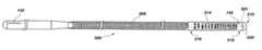
- FIG. 1is a side, fragmented, partially crossectional, view of one embodiment of a catheter guidewire apparatus configured in accordance with the principles of the present invention
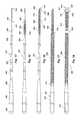
- FIG. 2is a side, fragmented, view of a portion of a guidewire showing different types of cuts or etchings which may be utilized in a solid or tubular guidewire in accordance with principles of the present invention
- FIG. 3is a side, fragmented, view of the tip of a guidewire with radiopaque coil or band wrapped thereabout, in accordance with principles of the present invention
- FIGS. 4 and 5show side, fragmented views of two embodiments of guidewires formed with cuts, in accordance with principles of the present invention
- FIG. 6is a side, fragmented view of a tapered guidewire formed with cuts, in accordance with principles of the present invention.
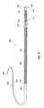
- FIG. 7is a side, fragmented view of a solid guidewire formed with a coiled tip, in accordance with principles of the present invention.
- FIG. 8is a graph of guidewire tensile strength compared to bending stiffness for a micromachined guidewire in accordance with principles of the present invention.
- FIG. 9is a graph of the ultimate torsional strength of a micromachined guidewire in accordance with principles of the present invention compared to its bending stiffness;
- FIG. 10is a graph of the torsional stiffiess of a micromachined guidewire in accordance with principles of the present invention compared to its bending stiffness;
- FIG. 11is a graph showing the ratio of torsional stiffness to bending stiffness of a micromachined guidewire in accordance with principles of the present invention compared to its bending stiffness;
- FIGS. 12 a, 12 b, and 12 cshow cross-sectional views of guidewires disposed within lumens of circular and elliptical catheters
- FIG. 12 dshows the potential serpentine path of a guidewire through a catheter which tends to wedge the guidewire within the catheter
- FIG. 13shows a perspective, partially fragmented, view of a guidewire in accordance with principles of the invention in another embodiment
- FIG. 14shows a side view, partially fragmented, of a core wire of the guidewire of FIG. 13 illustrating the grind profile
- FIG. 15shows a side view, partially fragmented, of a core wire of the guidewire of FIG. 13 with a medial stainless steel wire coil added;
- FIG. 16shows a side view, partially fragmented, of a core wire of the guidewire of FIG. 13 with a medial wire coil and distal marker coil added;
- FIG. 17shows a side view, partially fragmented, of a core wire of the guidewire of FIG. 13 with a medial wire coil and distal marker coil and proximal stainless coil added;
- FIG. 18shows a side view, partially fragmented, of a core wire of the guidewire of FIG. 13 with a medial wire coil, distal marker coil, proximal stainless coil and micromachined tubing added at a distal tip portion;
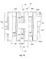
- FIG. 19shows a fragmentary perpsective view of a portion of a micromachined tubing segment such as shown in FIG. 18, in accordance with principles of the invention
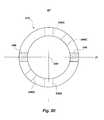
- FIG. 20shows a crossectional view, taken along line 20 — 20 in FIG. 19 of the micromachined tube shown in FIG. 19;
- FIG. 21shows a fragmentary perpsective view of a portion of a micromachined tubing segment such as shown in FIG. 19 subjected to torsional forces, illustrating deformation of the tubing;
- FIG. 22shows a cut orientation distribution progressing in an axial direction along a micromachined guidewire segment
- FIG. 23shows a fragmentary side view of a portion of a micromachined tubing segment illustrating a cut orientation distribution in another embodiment
- FIG. 24shows a diagram further illustrating the cut set distribution shown in FIG. 23 .
- the guidewire 200includes a proximal end 204 a distal end 208 , and a midportion 210 disposed therebetween, with the proximal end being mounted in a conventional pin vise type torquing chuck 212 .
- the guidewire 200is preferably constructed of a material including nickel titanium alloy, and may range in size from about 0.008 inches to about 0.090 inches in diameter and from about 135 to 300 centimeters in length.
- the guidewire 200can also be made of other materials, for example stainless steel. Four conventional preferred diameter sizes are 0.008 inches, 0.014 inches, 0.016 inches and 0.035 inches.
- Cuts, slots, gaps or openings 216 and 220are formed in the guidewire 200 along the length thereof, including the midportion 210 , either by saw cutting (e.g., by a diamond grit embedded semiconductor dicing blade), etching (for example using the etching process described in U.S. Pat. No. 5,106,455), laser cutting, or electron discharge machining.
- the cuts 216are angled to allow for a longer cut and thus greater flexibility, whereas cuts 220 are generally perpendicular to the longitudinal axis (long dimension) of the guidewire.
- the cutsare specifically configured to form transverse and axial beams therebetween within the body of the guidewire.
- This configurationallows the cuts and beams to interact to provide for lateral flexibility in the guidewire, while maintaining improved torsional stiffness.
- the flexure profile and torsional stiffness of the guidewiremay be selectively and relatively independently modified. Generally, the more closely spaced the cuts and the greater their depth, the more flexible will be the guidewire. However, modification of the exact shape, orientation, and spacing of the cuts will also allow selective modification of flexibility while preserving the desired torsional characteristics of the member.
- the distal end 208 of the guidewire 200may be preshaped with a curve, as shown, to allow for directing the guidewire around curves and bends. To maintain flexibility in the distal end 208 , cuts may also be provided on that end. Advantageously, the tip is rounded to minimize the chance of trauma to body tissue. Also formed on the distal end 208 is a radiopaque marker or band 224 .
- the band 224may be gold or platinum alloy (for X-ray fluoroscopy) or gadolinium or dysprosium, or compounds thereof (for MRI) and may be formed on the distal end 208 by deposition, wrapping or use of shape memory alloy (NiTi) effect to “lock” the band in place around the end.
- FIG. 2illustrating a portion of another exemplary guidewire 230
- three different examples of types of cuts 234 , 238 and 240can be appreciated.
- These types of cutsprovide a kind of built-in flexure “stop” to prevent further flexure of the guidewire when sides of these cut openings close to contact one another and prevent further flexure in that direction.
- Wedge shaped cuts 234may be formed on opposite sides of the guidewire 230 , with the greater width of the wedge being at the bottom of the cut.
- T-shaped cuts 238may likewise be formed on opposite sides of the guidewire 230 , with the cross piece of the T being at the bottom of the cut. Cuts 240 are generally circular as shown.
- cut shapescould also be provided to meet the needs of the user.
- the cuts 234 , 238 , and 240are shown oppositely oriented, but it will be apparent that the cuts could also be formed at circumferentially-spaced locations about the guidewire, or at alternating locations such as shown and described in more detail with regard to, for example, FIG. 5 .
- All three types of cuts shown in FIG. 2form an integral axial beam section, shown in cross-hatch as areas 232 , 236 , and 242 , respectively, between oppositely disposed cuts.
- This configurationprovides at least two distinct benefits. First, it allows the beam section to be longer than the gap of the flexure stop. This allows the amount of strain in the beam prior to stop engagement to be controlled by varying the ratio of beam length to gap size, allowing more flexibility, i.e. less bending resistance.
- the location and shape of the beam section 232 , 236 , or 242also greatly influences the torsional characteristics of the guidewire 230 .
- torsional strengthis primarily provided by the outer portion of the cross section of a member.
- a relatively thin-walled pipewill have nearly the same torsional strength as a solid bar of the same diameter because the central portion of the cross section of the solid bar contributes relatively little to torsional strength.
- the portion of the beam sections 232 , 236 , or 242 comprising the outer portion of the cross section of the guidewireare most important in efficiently transmitting torque.
- the axial beamsare more or less effective in transmitting torsional forces from one side to the other of the cuts 234 , 238 , and 240 depending on their shape.
- beam 232is relatively long (measured in the direction of the long axis of the guidewire), but is relatively deep (measured transverse to the long axis) and will therefore transmit a relatively large amount of torsional force.
- Beam 236is longer and thinner than beam 232 , and will therefore transmit a smaller amount of torsional force across the cut 238 .
- beam 242is the shortest and configured to transmit the greatest amount of torsional force. However, given the size and shape of cuts 240 , this configuration may provide the greatest flexibility.
- the flexibility of the guidewire sectionmay be selectively altered without affecting the size or strength of the axial beam section.
- the flexibility and torsional strength of the guidewiremay be selectively and relatively independently altered.
- longitudinally adjacent pairs of cutsmay be rotated with respect to each other by about 80-90 degrees around the axis of the wire provide flexure laterally in multiple directions.
- the cutsmay be located to provide preferential flexure in only one, two, three, etc. directions, if that is desired.
- the cutscould be randomly formed to allow bending (flex) equally, non-preferentially in all directions or planes. This could be achieved by circumferentially spacing the cuts.
- FIG. 3illustrates an alternative embodiment for applying a radiopaque marker to the distal end of a guidewire 244 , shown in side, fragmented view.
- An annular trough or channel 248is formed at the tip of the guidewire 244 , and a radiopaque wire coil, preferably made of platinum alloy, is wound about the guidewire in the channel.
- the coil 252could be welded or soldered to itself and/or the guidewire to hold it in place at the tip of the guidewire 244 .
- a gold or platinum bandrather than a coil is used with a nickel titanium alloy guidewire
- the guidewirecould be cooled and deformed to allow the band to be placed on the wire and then when the guidewire is returned to room temperature, the band would be maintained in place on the guidewire without the need for welding or soldering or other joining mechanism.
- a coilexcept forjoining the coil to itself.
- FIG. 4is a side, fragmented view illustrating a solid guidewire 260 formed with opposing cuts 262 , 264 spaced along a portion of the guidewire, and opposed cuts 266 , 268 rotated 90 degrees from said opposed cuts 262 , 264 .
- the rotated cuts 266 , 268are preferably arranged in opposing pairs, with opposite cut 266 corresponding to 268 not visible on the far side of the guidewire.
- the cutscould be formed to provide preferential bending (flex) in one plane, or could be positioned to allow bending in multiple planes. This could be achieved, for example, by rotating adjacent pairs of cuts by 45 degrees with respect to one another or some other selected angular amount 0-90 degrees.
- transverse beam sections 263 between adjacent opposing cuts 262 , 264are shaded in FIG. 4 . It will be apparent that the pairs of rotated cuts 266 , 268 will also form transverse beams therebetween, except that these beams will be oriented at an angle of 90 degrees relative to the beams 263 .
- FIG. 5is a side, fragmented view of a solid guidewire 270 formed with staggered or offset cuts 274 , 275 on opposite sides of the guidewire.
- a curved distal end 278is also includes a radiopaque marker band 280 .
- certain pairs of offset cutscould be rotated with respect to the other pairs, to thereby control direction of flexure.
- This configurationalso presents particular advantages regarding torsional control.
- opposed cutsproduce thin flexure transverse beams 272 between each pair of opposed cuts. The dimensions and flexure properties of these beams are determined by the depth and separation of the cuts and so the flexibility of a guidewire with opposed cuts may be controlled by varying these parameters as well as the width of the cuts.
- Offset cutsas indicated in FIG. 5, produce much larger flexure beams 272 in the area between each pair of adjacent cuts. As will be expected, these large beams are able to transmit a relatively large amount of torsion.
- this sectionwill also comprise relatively thin axial beams 276 between the base of each cut and the opposing side of the guidewire.
- FIG. 6is a side, fragmented view of a solid guidewire 284 having an enlarged proximal section 288 , which provides more torquability, and a narrowed distal section 292 , covered by a hydrophilic polymer sleeve 294 .
- the enlarged sectioncould be 0.014 inches in diameter whereas the narrowed section could be 0.010 inches in diameter.
- the distal end 296 of the guidewire 284is formed with cuts as earlier described. Of course, cuts could also be provided at other locations in the narrowed section 292 or in the enlarged section 288 , to increase flexibility, while maintaining high torsional stiffness.
- FIG. 7is a side, fragmented view of a solid guidewire 300 having a tapered distal end 304 about which is wrapped a coil 308 made, for example, of platinum alloy. Disposed at the tip of the distal end 304 of the guidewire and in the end of the coil 308 is a solder ball 312 . Cuts 316 may also be formed in the guidewire 300 as discussed earlier. In addition to the use of cuts to control the flexure of a guidewire, nickel titanium alloy guidewires can be heat treated to vary the flexure characteristics. For example, selective annealing along the length of the wire can change stress/strain relationship of the material, and thus the flexure.
- the guidewirescan be made “flow directable” by providing highly flexible distal ends. “Flow directability” means that the distal end of the guidewire tends to “flow” with the blood around curves and bends in a vasculature passageway.
- the surface of the guidewiremay be electropolished to increase the smoothness thereof, and additionally, a lubricious coating may be applied to the surface of the guidewire—such coatings might illustratively include silicone based oil and/or polymer or hydrophilic polymers.
- a lubricious sleeve made, for example, of a hydrophilic polymercould also be provided for disposal over the guidewire. Such polishing has the additional benefit of increasing fatigue failure resistance.
- FIGS. 8-11provide graphical representation of the improvement this invention provides over conventional prior art devices. These graphs depict comparative test results of catheter guidewires formed according to this invention, showing the strength of catheter guidewires in accordance with principles of the invention compared to prior art devices, and the relative preservation of torsional strength relative to flexibility.
- FIG. 8is a graph of guidewire tensile strength compared to bending stiffness for the micromachined guidewire of the present invention.
- the individual (square) data pointsrepresent tension test results for micromachined guidewires.
- the ultimate tensile strength in poundsis indicated on the vertical axis, while the bending stiffness in psi is given on the horizontal axis.
- Below the horizontal axisis a second axis noting the size of stainless steel wire which would correspond to the respective bending stiffness shown in the horizontal axis.
- the solid linerepresents the theoretical tensile strength for equivalent solid wires.
- FIG. 9is a graph showing ultimate torsional strength of the micromachined guidewire of the present invention compared to its bending stiffness.
- the vertical axisshows the ultimate torsional strength of the guidewire in units of pound-inches, and the horizontal axis shows the bending stiffness in psi.
- the square data pointsrepresent actual test results of micromachined catheter guidewires, and the solid line represents the theoretical results for a catheter guidewire of solid circular cross section. It will be apparent from this graph that as the bending stiffness (or size) of the conventional guidewire decreases, the expected or theoretical torsional strength also decreases. This is depicted by the solid line.
- FIG. 11is a graph showing the ratio of torsional stiffness to bending stifftess of the micromachined guidewire of the present invention compared to its bending stiffness.
- the vertical axisrepresents a ratio of torsional stiffness to bending stiffness (JG/EI), with the result that the expected relationship of bending stiffness to torsional stiffness (the solid line) is now a horizontal line.
- this lineis set equal to unity, in order to more graphically show the actual results of the inventors' tests.
- the torsional strength of the micromachined guidewireswas more than 30 times more than expected.
- the condition indicated by FIG. 11represents some unexpected results.
- the goalwas primarily to increase the flexibility.
- the inventorsnoticed a corresponding (and expected) decrease in torsional strength. This is a significant problem with catheter guidewires because guidewires with low torsional strength cannot be manipulated as easily, and are more likely to become wedged or jammed into the catheter or vasculature of the patient.
- a torsionally weak guidewirewhen the user twists the proximal end, there is a significant delay in the transmission of the torque to the distal end.
- FIG. 12shows cross-sectional views of guidewires disposed within the lumen of circular and elliptical catheters.
- a circular catheteris advanced into the vasculature of a patient and navigates curves and other tortuous routes, the cross-sectional shape of the catheter frequently tends to flatten out in places into a more elliptical cross-section.
- a guidewire 400is disposed in catheter 402 having a circular cross-section, it would have no preference as to its location within the cross section—its position will present a state of physical equilibrium regardless of its location because all locations are the same.
- the guidewire 400 in a central locationrepresents a state of unstable equilibrium, like a ball sitting on the top of another ball.
- the resultis that the guidewire will naturally gravitate to a point of stable equilibrium 406 , in the tight corner of the catheter lumen.
- the area of contact between the guidewire and the catheteris much larger, resulting in large frictional forces which will hinder the easy movement of the guidewire within the catheter.
- FIG. 13shows the potential serpentine path of a torqued guidewire 420 through a catheter 422 .
- an axial driving force(denoted Fwire in FIG. 13) is applied to the guidewire 420 , it will be converted into an axial force (denoted Faxial) and a perpendicularly oriented wedging force (denoted Wedging Force) which will tend to jam the guidewire within the catheter.
- an exemplary guidewire 500in accordance with principles of the invention, and giving the advantages discussed above, comprises a proximal portion 502 extending from a proximal end 504 to a first transition portion 506 where the diameter of the guidewire changes.
- This proximal portioncomprises a stainless steel core wire 501 configured as solid wire of circular cross section.
- the core wire in the proximal portionis covered with a low friction coating.
- PTFEis used to coat the proximal portion in the illustrated example.
- the proximal portionhas a diameter as large as needed to transmit torque sufficient for the intended use of the guidewire.
- a diameter of about 14 thousandths of an inchis appropriate, and is used in the illustrated example.
- the stainless steel wireis ground to a smaller diameter, transitioning over an axial length sufficient to provide a smooth transition. This is about 2 inches in one embodiment.
- the guidewire 500has a more complex configuration.
- a proximal coil 508is disposed over the stainless core wire 501 .
- the core wirecontinues to the distal end 510 of the guidewire, the proximal coil overlaying the core wire as will be further explained.
- the proximal coilis attached to the core wire at the first transition portion 506 by a proximal solder joint 512 at a point where the inner diameter of the coil matches the outer diameter of the core wire.
- the diameter of the core wirecontinues to decrease under the proximal coil, and beyond it in accordance with a grind profile that will be described below.
- the guidewire 500in an exterior aspect comprises a micromachined tubing 514 formed of a material comprising a superelastic material such as NiTi alloy.
- This micromachined tubingis very important to functionality of the catheter guidewire, as it transmits torque to the distal end 510 of the guidewire but is very flexible.
- the micromachined tubingoverlays additional structure as will be described below.
- the micromachined tubingis attached to the proximal coil 508 via other underlying structure, and the core wire 501 at a medial solder and glue joint 516 .
- This jointis important as it is the point where the torsional force “carrying capacity” of the core wire 501 is substantially equal to that of the micromachined tubing. A force path is therefore established which extends through the core wire from the proximal end 504 of the guidewire 500 to the medial solder and glue joint 516 , then continues through the micromachined tubing 514 to the distal end 510 of the guidewire 500 .
- the outer diameter of the proximal coil 508is substantially the same as the proximal portion 502 of the core wire.
- the outer diameter of the micromachined tubing 514 at the distal tip portion 511 of the guidewire 500is also approximately the same, all being about 14 thousandths of an inch.
- the proximal coilis about 11 inches long and the distal tip portion comprising the micromachined tubing is about 2 inches long.
- the distal tip portioncan be given a curved or other bent configuration is known in the art.
- the micromachined tubing, underlying structure (not shown), and the core wire 501are attached at a distal solder and glue joint 518 .
- the core wirehas a very small diameter at the distal end, the grind profile reducing it to approximately 2 thousandths of an inch prior to reaching that point.
- the distal solder and glue jointcomprises an adhesive 520 which is formed into a rounded configuration at the distal end of the guidewire to form an a-traumatic tip.
- FIGS. 14-18the construction of an exemplary guidewire configuration will be described in more detail.
- the core wire 501alone is seen to advantage, with the grind profile appreciable.
- the corewirehas a rounded configuration at the proximal end 504 of the wire, and the proximal portion 502 is as previously described, and is about 65 inches in length in one exemplary embodiment.
- the grind profileextends about 14 inches further to the distal end 510 of the guidewire 500 .
- a second 522 , and a third 524transition portion are provided.
- the core wirehas a first reduced diameter portion 526 having a length of about 6 inches and a diameter of about seven and a half thousandths of an inch.
- the second transition portionis also about 2 inches in length, and the diameter further reduces from that of the first reduced diameter portion to about five and a half thousandths of an inch. This diameter is maintained for about two and a half inches, to form a second reduced diameter portion 528 .
- the diameterfurther decreases to about two thousands of an inch, which is maintained to the distal end 510 as mentioned, to form a third reduced diameter portion 530 .
- This third transition portionis about one tenth of an inch in length, and the third reduced diameter portion is about one and nine tenths inches in length in the illustrated exemplary embodiment.
- the third reduced diameter portionis configured to be extremely flexible as will be appreciated, but retain sufficient axial strength to help prevent distal tip separation on withdrawal of the guidewire from a position where the tip may be stuck in the anatomy, and to assist in facilitating pushability of the distal tip portion 511 of the guidewire.
- a medial coil 532is attached to the core wire 501 at the third transition portion 524 .
- the medial coilhas an outer diameter substantially equal to the inner diameter of the proximal coil 508 and the inner diameter of the micromachined tubing 514 . It is attached by soldering, and this location of attachment on the third transition portion is that of the medial solder and glue joint mentioned above. Also, it will be noted that the location is near the proximal end of the third transition portion, so that the diameter of the core wire at this location is substantially the same as the second reduced diameter portion 528 .
- the location on the grind profileis important as it represents the “end of the line” for torque transmission through the core wire, and the diameter of the corewire is directly proportional to the amount of torsional force that can be transmitted, the location and diameter are chosen in conjunction with selection of the parameters of the micromachined tubing so that the “carrying capacity” for torque is substantially equal.
- a mis-matchrepresents an inefficiency in this regard and is to be avoided unless for some design objective a discontinuity in torquability is desired at this point.
- the medial coil 532is formed of stainless steel in one embodiment, and has a proximal unwound portion 534 at its proximal end, to aid in more secure bonding to the core wire 501 as a longer length of coil wire can be bonded due to slight deformation thereby allowed to follow the grind profile.
- the medial coilhas a distal unwound portion 536 which will be further described next below.
- a distal coil 538is disposed over the third reduced diameter portion at the distal tip portion.
- the proximal end of the distal coilis provided with an unwound portion 540 which cooperates with the distal unwound portion 536 of the medial coil to form a secure interlock by intertwining of the coils, then soldering.
- the distal coilcan be of slightly larger diameter wire, due to the reduced grind profile it overlays, but the outside diameter is held to be slightly less than that of the inside diameter of the micromachined tubing (not shown) as will be described.
- the distal coilis formed of a radiopaque material in the illustrated embodiment to provide enhanced fluoroscopic visibility.
- the distal coilthus acts as a marker to aid in navigation of the guidewire within the anatomy of a patient.
- the drawing figuresare not to scale, and the distal coil can be considerably longer than the medial coil 532 .
- the distal end of the distal coilis soldered to the core wire 501 adjacent the distal end 510 at the location of the distal solder and glue joint 518 .
- the guidewire 500 apparatusis assembled by attaching the medial spring 532 to the core wire, then attaching the distal (marker) coil 538 to the medial coil, then the proximal coil is slipped over the assembly and soldered to the core wire 501 at the proximal solder joint 512 and to the medial coil 532 at the location of the medial solder and glue joint 516 .
- the solder used throughoutis a silver or gold alloy solder or another material regulatory-approved for such use.
- fabrication of the catheteris completed by placement of the micromachined tubing 514 over the distal tip portion 511 . It is fixed in place by securing it at its proximal end at the medial solder and glue joint 516 by means of a suitable adhesive such as a UV cured regulatory-approved adhesive such as Dymax, and by attaching the distal end to the distal tip of the core wire 501 , and also to the distal (marker) coil by an identical or similar adhesive.
- a suitable adhesivesuch as a UV cured regulatory-approved adhesive such as Dymax
- this adhesivewhen cured forms a rounded tip 520 to reduce trauma, and completes the distal solder and glue joint which holds together the core wire, distal marker coil, and the micromachined tubing at the distal end 510 of the guidewire.
- the guidewirecan further include a micromachined “barcode” identification 142 located at a convenient location such as adjacent the proximal or distal end of the guidewire.
- the barcodeis made by very lightly scoring the surface to form a binary code to encode identifying information regarding the catheter. This is done by a similar process to that used to micromachine the tubing 514 or another guidewire as discussed above and as follows.
- the advantage of such a marking systemis that individual guidewires can be identified, enabling “lot of one” custom manufacturing and marking of one to as many as desired guidewires 500 .
- FIG. 19discussion of the micromachined tubing 514 more specifically should include mention of how the tubing is made.
- FIG. 19discussion of the micromachined tubing 514 more specifically should include mention of how the tubing is made.
- further details regarding fabrication of the tubingcan be found in copending U.S. patent application Ser. No. 09/470,606, the disclosure of which is hereby incorporated herein by reference.
- a unique construction combined with optimizationprovides increased torquability while allowing flexure, so as to be compliant with tortuous vasculature in accessing a target site within the patient's anatomy.
- the present inventionis directed to maximizing torque transmission, while minimizing resistance to bending of a guidewire body, for example in the tubular member 514 shown.
- a tubular structureis implicated, even though a solid member may be used. Therefore the following discussion will apply to solid wires as well, though it will be understood that this is because an assumption is made that the inner portion of the wire is not contributing appreciably, and the structure other than a tubular portion of it is being ignored.
- a tubular configurationis advantageous as other structure can be placed inside, as in the case of the illustrated embodiment given by example herein employing a tubular micromachined tubing segment 514 at a distal tip portion 511 .
- One way in which the guidewire distal portion is optimizedis using superelastic material, preferably formed as a tube, micromachining the tube to create a structure which maximizes torque transmission while minimizing resistance to bending.
- a section of micromachined tubing 514 , having slot-like cuts formed thereinis shown to illustrate the structure.
- the cutsare opposed cuts in the illustrated embodiment. That is, two cuts are made from opposite sides of the tubing at the same location along the longitudinal axis of the tubing. The depth of the cuts is controlled to leave a segment 546 of the tubing wall extant between the cuts on each of the opposite sides (180 degrees apart) of the tubing.
- segmentswill acts as “beams” as discussed above to carry forces across the cut area at that location along the longitudinal axis 548 of the tubing.
- axial beamsAs a matter of convention such segments will be referred to as “axial beams” 546 as they are disposed to carry or transfer forces in roughly an axial direction from adjacent structure on one side to adjacent structure on an opposite side.
- a pair of opposed cuts 550is made adjacent to the cuts previously described ( 544 ) the location of the cuts is made such that the axial beam(s) 546 A formed by the second set of cuts is displaced circumferentially from the adjacent axial beam(s) 546 . This of course is done by rotation of the tube through some angle relative to the saw used to cut the tubing before cutting. This can be seen in FIG. 20 .
- the amount of rotationis selected with each successive cut to give a pattern calculated to facilitate torque transmission while also facilitating bending of the tube after machining and to mitigate whipping.
- This cutting distributionwill be discussed below. With reference again to FIG. 19, what is important to this discussion is that in addition to axial beams, other beams, which by convention we call transverse beams 552 are created.
- the transverse beams 552are defined in this example as the curved portion of the tubing wall between adjacent cuts 544 , 550 and adjacent axial beams. e.g. 546 and 546 A. As will be appreciated, these transverse beams carry forces from a particular set of axial beams to the two adjacent axial beams created by an adjacent set of cuts.
- this matchingcan be done in tubing of constant cross section by variation of several parameters, namely the location (spacing 555 between), width 556 , and depth 558 of cuts (e.g. 544 , 550 ) made. Wider spacing of cuts creates wider transverse beams, shallower cuts create wider axial beams. Likewise more closely spaced cuts create narrower transverse beams, and deeper cuts create more narrow axial beams. Wider cuts create longer axial beams.
- the configuration of the micromachined tubingis defined by calculation, using well-known formulas for stress and stress/strain.
- the design processcan further include finite-element analysis of the configuration to give localized stress and strain values. The calculations are repeated as necessary using incrementally changing parameters to optimize the design taking into account the concepts set forth herein.
- Another way of optimizing the designis to match, insofar as possible, the resistance to fatigue failure of the axial and transverse beams.
- Thiscan be modeled, and can also be determined empirically.
- tubing samplescan be spun in a tube having a bend therein, counting the revolutions to failure. Examination after failure will show failure by crack propagation through an axial or through a transverse beam.
- the relative geometriescan be adjusted to balance the resistance to fatigue failure.
- the micromachined tubingwill fail at a corner between an axial and transverse beam, as stress concentration there will control if the resistance to fatigue failure is sufficiently matched between the beam elements.
- a saw blade of a specified widthwill be used to make the cuts. And accordingly the width of all cuts is held to this value.
- a diamond silicon wafer cutting saw blade(as is used in the microprocessor and memory chip manufacturing art—not shown) about one thousandth of an inch wide is used to make the cuts (e.g. 544 ). While it is possible to make wider cuts by making a first cut, then moving the wire relative to the blade by a distance up to a width of the blade, and repeating as necessary for wider cuts, speed of fabrication is higher if a single cut is used. Therefore, using this constant cut width, the possible variables are depth 558 of cut and spacing 555 .
- cut width 556is to be held constant, in one embodiment the other parameters are selected as follows.
- the bending stiffness desired at any selected location along a length of tubingis obtained by selection of an appropriate spacing 555 between cuts.
- selection of a distance between the set of opposed cuts to be made (e.g. 546 A) and the last set of opposed cuts made (e.g. 546 )will define, by means of the calculations, the depth of the cuts to be made as the distance between cuts defines the width of the transverse beams, and the width of the transverse beams is related to the width of the axial beam by the condition of equality of strain values to be obtained for a given applied torsional force 554 as mentioned.
- the locations of the axial beams 546will be set by the relative angular displacement of the adjacent sets of opposed cuts, as will be described, and hence the width and the length of the transverse beams 552 will be known.
- the width of the axial beams to be createddepends on the depth of cut.
- the length of each axial beamis the same and equal to the constant cut width (e.g. one thousandth of an inch in the illustrated embodiment).
- the depth of cutis determined by comparison of the strain in the each of the resulting axial beams (they are assumed to be the same, though in fact they may not be in all cases due to differing force distribution due to variations in geometry) and then matching the strain in the axial beam(s) (e.g.
- the strain in the transverse beam(s)(e.g. 552 ).
- the strain in the transverse beam(s)e.g. 552 .
- four transverse beamsare created between each set of opposed cuts.
- the resulting strainsare evaluated in each of the four beams, but in one embodiment another simplifying assumption is made that the strain in the two shorter transverse beams is the same, and likewise the strain in the two longer transverse beams is the same.
- the greater of the resulting strains in the transverse beamsis compared with the strain in the axial beams. This represents the force transmission path for transfer of the torque.
- the depth of cut 558is varied until the strains are matched. This value is then used in making the cuts at that location.
- axial and transverse beamsthere is a practical limit on the size of axial and transverse beams. Too large at the desired advantages are lost, too small and imperfections in materials and variations within the tolerances in machining can compromise performance. This may be governed by the thickness of the tubing if tubing is used, the size of the saw blade, accuracy of the machining apparatus, etc. Generally speaking, axial or transverse beams having dimensions on a par with or smaller than the width of the cutting blade used to micromachine them are avoided.
- Further refinement of the designcan be by matching fatigue failure resistance as discussed above. Further reduction of opportunities for development of cracks in the material is desirable, and rounding of the corners of the structure to reduce stress concentrations, and polishing of the structure, by electropolishing or abrasives as described elsewhere herein, or some other method is desirable as it further rounds corners and polishes surfaces to reduce the probability of crack propagation.
- the design processthen, in summary, is in one embodiment to space the cuts (e.g. 544 , 550 ) apart along the axis 548 of the tubing so as to provide bending as desired.
- the cutswill be closer together to give less resistance to bending, and more spaced apart to give more resistance to bending. (See, for example FIGS. 13 and 18, where the tubing segment 514 becomes more flexible toward the distal end 510 of the guidewire 500 .)
- the stiffnesscan be controlled by means of variation of the spacing 555 of the cuts, the other parameters being selected as appropriate as described above.
- the bending stiffness of the tubingcan vary along the longitudinal axis, for example being made to gradually become less stiff toward the distal end, by gradually decreasing the spacing between cuts as in the above example.
- the depth 558 of the cutsis calculated using stress/strain relationships to match the strain in the axial 546 and transverse 552 beams created.
- the strain in the axial beamsis matched to that of the greatest calculated in the previously calculated transverse beams.
- another methodcould be employed, for example comparing the strain in a given axial beam 546 A to that of the transverse beams 552 , 552 A on either side of the axial beam along the axis 548 of the tubing 514 to match the strain.
- the average of the highest strain values in transverse beams 552 , 552 A 1 , 552 A 2( 552 A 1 and 552 A 2 being of unequal length the strains may be markedly different), on either side can be used to match the strain in the axial beam 546 A under consideration.
- varying the thickness of the axial beam(s)affects the forces transmitted to the transverse beams and therefore varies the stress and strain in the transverse beam; so, as a result, many iterations of these calculation steps can be required to optimize the design.
- the objectis to provide a distribution of cut orientations along the length of the tubing that minimizes “preferred” bending directions of the micromachined tubing 514 giving rise to undesirable effects collectively referred to as “whip” or a deviation of expected rotational result at the distal tip of the guidewire from that expected by the user from rotational inputs made at the proximal end of the guidewire by turning the collet fixture 212 .
- one way of organizing the cut distribution to minimize whipis to assume a first cut pair of opposed cuts (180 degrees apart) and a second pair of opposed cuts immediately adjacent will be offset by an angle of ninety degrees. Collectively the four cuts will be referred to as a first cut set 560 . A second cut set 562 of adjacent opposed cuts oriented ninety degrees apart is subsequently made, these being oriented with respect to the first cut set (designated arbitrarily as oriented at 0 degrees) so as to be rotated 45 degrees. The next similar cut set 564 is oriented at 22.5 degrees, and the next at 67.5 degrees, and so on in accordance with the distribution graphically illustrated in the figure. The sequence repeats every 64 cut sets (128 opposed cuts, and 256 cuts in total).
- the cut distributionis defined by a helical pattern.
- a first cut pair 570is at zero degrees.
- a second cut pair 572is rotated with respect to the first through a chosen angle “x”. For example, this angle can be about 85 degrees.
- a third cut pair 574is oriented by rotation through an angle equal to 2x, or 170 degrees in the exemplary embodiment. This pattern is continued, as the next cut pair (not shown) is oriented at 3x or 255 degrees, etc. continuing to turn in the same direction and by the same magnitude of angular rotation, x.
- the bending axis 576 formed by the first cut pair 570is oriented at 0 degrees; and the next bending axis 578 formed by the second cut pair is oriented at 85 degrees in the example, and the third bending axis 580 at 170 degrees, and so on.
- the patternwill repeat after 72 cut pairs (144 total cuts) in the illustrated example where x is equal to 85 degrees.
- the medial solder/glue joint ( 516 in the FIGs.)is located is substantially at the point where the grind profile drops to about 0.005 inch diameter.
- the NiTi tubing segment which has been micromachined as described aboveprovides a superior path for transmission of torque to the distal tip 510 of the guidewire from that point while at the same time facilitating bending.
- the exemplary embodimentillustrates that the guidewire configuration can be optimized for cost as well, the less expensive stainless steel core wire and conventional coil configuration being provided up to the point where better characteristics are obtainable with a micromachined configuration.
- guidewirecan include providing lubricious coatings on components distal of the proximal portion 502 previously described as including such a coating.
- a silicone coatingas is known in the art can be applied in one of the many manners known in the art.
- micromachined tubingcan be deburred after micromachining if necessary.
- an acid wash etching processcan be used to deburr the inner surfaces, and the tubing can be placed on a mandrel and turned while being subjected to an abrasive jet to dauber and round the micromachined edges to minimize the possibility of catching on anatomy.
- the micromachining patterncan be altered to provide preferred bending directions. This can be useful in customizing the guidewire to reach a target location within a particular anatomical structure, or even a particular individual patient.
- a MRI or CAT scancan produce a data set from which a preferred access route, for example vasculature to a target site, can be constructed in three dimensions.
- the guidewirecan be micromachined to provide locally variable flexibility as needed to facilitate the traversing the last critical distance to the target site.
- a catheter individually customized for that patentcould be made from that data set (for example sent to the manufacturer via the Internet) and shipped out to the user very rapidly, since micromachining is a computer-controlled automated process that could be customized based on the data set in accordance with another automated procedure.
- This guidewire (or catheter for that matter)could be individually identified by a bar code as described herein.
Landscapes
- Health & Medical Sciences (AREA)
- Life Sciences & Earth Sciences (AREA)
- Biophysics (AREA)
- Pulmonology (AREA)
- Engineering & Computer Science (AREA)
- Anesthesiology (AREA)
- Biomedical Technology (AREA)
- Heart & Thoracic Surgery (AREA)
- Hematology (AREA)
- Animal Behavior & Ethology (AREA)
- General Health & Medical Sciences (AREA)
- Public Health (AREA)
- Veterinary Medicine (AREA)
- Media Introduction/Drainage Providing Device (AREA)
Abstract
Description
Claims (54)
Priority Applications (3)
| Application Number | Priority Date | Filing Date | Title |
|---|---|---|---|
| US09/746,738US6579246B2 (en) | 1999-12-22 | 2000-12-22 | Coronary guidewire system |
| AU2002246775AAU2002246775A1 (en) | 2000-12-22 | 2001-12-20 | Coronary guidewire system |
| PCT/US2001/049770WO2002062540A2 (en) | 2000-12-22 | 2001-12-20 | Coronary guidewire system |
Applications Claiming Priority (2)
| Application Number | Priority Date | Filing Date | Title |
|---|---|---|---|
| US17183899P | 1999-12-22 | 1999-12-22 | |
| US09/746,738US6579246B2 (en) | 1999-12-22 | 2000-12-22 | Coronary guidewire system |
Publications (2)
| Publication Number | Publication Date |
|---|---|
| US20020013540A1 US20020013540A1 (en) | 2002-01-31 |
| US6579246B2true US6579246B2 (en) | 2003-06-17 |
Family
ID=25002121
Family Applications (1)
| Application Number | Title | Priority Date | Filing Date |
|---|---|---|---|
| US09/746,738Expired - LifetimeUS6579246B2 (en) | 1999-12-22 | 2000-12-22 | Coronary guidewire system |
Country Status (3)
| Country | Link |
|---|---|
| US (1) | US6579246B2 (en) |
| AU (1) | AU2002246775A1 (en) |
| WO (1) | WO2002062540A2 (en) |
Cited By (193)
| Publication number | Priority date | Publication date | Assignee | Title |
|---|---|---|---|---|
| US20030009208A1 (en)* | 2001-07-05 | 2003-01-09 | Precision Vascular Systems, Inc. | Torqueable soft tip medical device and method of usage |
| US20030060732A1 (en)* | 1996-05-24 | 2003-03-27 | Jacobsen Stephen C. | Hybrid catheter guide wire apparatus and method |
| US20030125709A1 (en)* | 2001-12-28 | 2003-07-03 | Eidenschink Tracee E.J. | Hypotube with improved strain relief |
| US20040111044A1 (en)* | 2002-07-25 | 2004-06-10 | Precision Vascular Systems, Inc. | Medical device for navigation through anatomy and method of making same |
| US20050182475A1 (en)* | 2003-09-02 | 2005-08-18 | Jimmy Jen | Delivery system for a medical device |
| US20050197597A1 (en)* | 2004-03-05 | 2005-09-08 | Medtronic Vascular, Inc. | Guidewire with hollow distal section |
| US20050234427A1 (en)* | 2004-04-19 | 2005-10-20 | Scimed Life Systems, Inc. | Hybrid micro guide catheter |
| US20050273020A1 (en)* | 2004-03-24 | 2005-12-08 | Whittaker David R | Vascular guidewire system |
| US20050277851A1 (en)* | 2004-03-24 | 2005-12-15 | Whittaker David R | Vascular guidewire control apparatus |
| US20060106407A1 (en)* | 2004-11-17 | 2006-05-18 | Mcguckin James F Jr | Rotational thrombectomy wire |
| US20060235502A1 (en)* | 2005-04-18 | 2006-10-19 | Medtronic Vascular, Inc. | Intravascular deployment device with improved deployment capability |
| US20070010762A1 (en)* | 2005-07-07 | 2007-01-11 | Ressemann Thomas V | Steerable guide wire with torsionally stable tip |
| US7169118B2 (en) | 2003-02-26 | 2007-01-30 | Scimed Life Systems, Inc. | Elongate medical device with distal cap |
| US20070100422A1 (en)* | 2003-09-02 | 2007-05-03 | Shumer Daniel H | Delivery system for a medical device |
| US20070112331A1 (en)* | 2005-11-16 | 2007-05-17 | Jan Weber | Variable stiffness shaft |
| US20070118201A1 (en)* | 2003-09-02 | 2007-05-24 | Pappas Jeffrey M | Delivery system for a medical device |
| US20070123805A1 (en)* | 2003-02-26 | 2007-05-31 | Boston Scientific Scimed, Inc. | Elongated intracorporal medical device |
| US20070135763A1 (en)* | 2005-12-12 | 2007-06-14 | Musbach Frank A | Micromachined medical devices |
| US20070179472A1 (en)* | 2005-03-24 | 2007-08-02 | Whittaker David R | Vascular guidewire control apparatus |
| US20070185415A1 (en)* | 2005-07-07 | 2007-08-09 | Ressemann Thomas V | Steerable guide wire with torsionally stable tip |
| US20070191865A1 (en)* | 2003-09-02 | 2007-08-16 | Pappas Jeffrey M | Delivery System For A Medical Device |
| US20070208405A1 (en)* | 2006-03-06 | 2007-09-06 | Boston Scientific Scimed, Inc. | Stent delivery catheter |
| US20070233039A1 (en)* | 2006-03-29 | 2007-10-04 | Vladimir Mitelberg | Joined metal tubing and method of manufacture |
| US20070250149A1 (en)* | 2006-04-21 | 2007-10-25 | Abbott Laboratories | Stiffening Support Catheters and Methods for Using the Same |
| US20070270779A1 (en)* | 2006-04-21 | 2007-11-22 | Abbott Laboratories | Support Catheter |
| US20070293821A1 (en)* | 2006-04-21 | 2007-12-20 | Abbott Laboratories | Systems, Methods, and Devices for Injecting Media Contrast |
| US20070293846A1 (en)* | 2006-04-21 | 2007-12-20 | Abbott Laboratories | Dual Lumen Guidewire Support Catheter |
| US20070299366A1 (en)* | 2006-06-08 | 2007-12-27 | Sharrow James S | Guidewire with polymer jacket and method of making |
| US20080045908A1 (en)* | 2006-08-16 | 2008-02-21 | Boston Scientific Scimed, Inc. | Medical device including a metallic tube fillet welded to a core member |
| US20080065014A1 (en)* | 2006-04-21 | 2008-03-13 | Abbott Laboratories | Systems, Methods, and Devices to Facilitate Wire and Device Crossings of Obstructions in Body Lumens |
| US20080077085A1 (en)* | 2006-09-27 | 2008-03-27 | Boston Scientific Scimed, Inc. | Catheter shaft designs |
| US20080077049A1 (en)* | 2006-08-24 | 2008-03-27 | Boston Scientific Scimed, Inc. | Elongate medical device including deformable distal end |
| US20080097395A1 (en)* | 2006-09-18 | 2008-04-24 | Boston Scientific Scimed, Inc. | Catheter shaft including a metallic tapered region |
| US20080097247A1 (en)* | 2006-09-06 | 2008-04-24 | Boston Scientific Scimed, Inc. | Medical device including structure for crossing an occlusion in a vessel |
| WO2008085167A1 (en)* | 2007-01-10 | 2008-07-17 | St. Jude Medical, Cardiology Division, Inc. | Steerable guide wire with torsionally stable tip |
| US20080294231A1 (en)* | 2007-05-16 | 2008-11-27 | Boston Scientific Scimed, Inc. | Stent Delivery Catheter |
| US20090118675A1 (en)* | 2007-11-02 | 2009-05-07 | Boston Scientific Scimed, Inc. | Elongate medical device with a shapeable tip |
| US20090118704A1 (en)* | 2007-11-02 | 2009-05-07 | Boston Scientific Scimed, Inc. | Interconnected ribbon coils, medical devices including an interconnected ribbon coil, and methods for manufacturing an interconnected ribbon coil |
| US7540865B2 (en) | 2003-03-27 | 2009-06-02 | Boston Scientific Scimed, Inc. | Medical device |
| US20090143768A1 (en)* | 2007-04-23 | 2009-06-04 | Interventional & Surgical Innovations, Llc | Guidewire with adjustable stiffness |
| US20090157048A1 (en)* | 2007-12-18 | 2009-06-18 | Boston Scientific Scimed, Inc. | Spiral cut hypotube |
| US20090156999A1 (en)* | 2007-12-13 | 2009-06-18 | Boston Scientific Scimed, Inc. | Coil member for a medical device |
| US20090157047A1 (en)* | 2007-12-13 | 2009-06-18 | Boston Scientific Scimed, Inc. | Medical device coatings and methods of forming such coatings |
| US20090177185A1 (en)* | 2008-01-03 | 2009-07-09 | Boston Scientific Scimed, Inc. | Cut tubular members for a medical device and methods for making and using the same |
| US20090264907A1 (en)* | 2008-04-18 | 2009-10-22 | Boston Scientific Scimed, Inc. | Medical device for crossing an occluded blood vessel |
| US20090275862A1 (en)* | 2008-04-30 | 2009-11-05 | Cook Incorporated | Guidewire and method of making same |
| US7632242B2 (en) | 2004-12-09 | 2009-12-15 | Boston Scientific Scimed, Inc. | Catheter including a compliant balloon |
| US20100048758A1 (en)* | 2008-08-22 | 2010-02-25 | Boston Scientific Scimed, Inc. | Lubricious coating composition for devices |
| US20100099952A1 (en)* | 2008-10-22 | 2010-04-22 | Boston Scientific Scimed, Inc. | Steerable Shaft Having Micromachined Tube |
| US20100145308A1 (en)* | 2008-12-10 | 2010-06-10 | Boston Scientific Scimed, Inc. | Medical devices with a slotted tubular member having improved stress distribution |
| WO2010096708A1 (en) | 2009-02-20 | 2010-08-26 | Boston Scientific Scimed, Inc. | Balloon catheter for placemnt of a stent in a bifurcated vessel |
| US20100217374A1 (en)* | 2009-02-20 | 2010-08-26 | Boston Scientific Scimed, Inc. | Torqueable Balloon Catheter |
| US7803142B2 (en) | 2005-02-02 | 2010-09-28 | Summit Access Llc | Microtaper needle and method of use |
| US7824345B2 (en) | 2003-12-22 | 2010-11-02 | Boston Scientific Scimed, Inc. | Medical device with push force limiter |
| US7841994B2 (en) | 2007-11-02 | 2010-11-30 | Boston Scientific Scimed, Inc. | Medical device for crossing an occlusion in a vessel |
| US20100305475A1 (en)* | 2007-04-23 | 2010-12-02 | Hinchliffe Peter W J | Guidewire with adjustable stiffness |
| US7850623B2 (en) | 2005-10-27 | 2010-12-14 | Boston Scientific Scimed, Inc. | Elongate medical device with continuous reinforcement member |
| US20100319815A1 (en)* | 2003-05-02 | 2010-12-23 | Dooley Bret A | Method of making shape memory alloy articles with improved fatigue performance |
| US7914467B2 (en) | 2002-07-25 | 2011-03-29 | Boston Scientific Scimed, Inc. | Tubular member having tapered transition for use in a medical device |
| US7914466B2 (en) | 1995-12-07 | 2011-03-29 | Precision Vascular Systems, Inc. | Medical device with collapse-resistant liner and method of making same |
| US20110077620A1 (en)* | 2009-09-30 | 2011-03-31 | Debeer Nicholas C | Guide Catheters |
| US20110130821A1 (en)* | 2008-06-05 | 2011-06-02 | Witold Styrc | Device for treating a blood flow conduit |
| US20110160680A1 (en)* | 2009-12-29 | 2011-06-30 | Cook Incorporated | Wire guide with cannula |
| US7993303B2 (en) | 2006-04-21 | 2011-08-09 | Abbott Laboratories | Stiffening support catheter and methods for using the same |
| WO2011123689A1 (en) | 2010-03-31 | 2011-10-06 | Boston Scientific Scimed, Inc. | Guidewire with a flexural rigidity profile |
| US8057430B2 (en) | 2009-02-20 | 2011-11-15 | Boston Scientific Scimed, Inc. | Catheter with skived tubular member |
| US8105246B2 (en) | 2007-08-03 | 2012-01-31 | Boston Scientific Scimed, Inc. | Elongate medical device having enhanced torque and methods thereof |
| US8137293B2 (en) | 2009-11-17 | 2012-03-20 | Boston Scientific Scimed, Inc. | Guidewires including a porous nickel-titanium alloy |
| WO2012106628A1 (en) | 2011-02-04 | 2012-08-09 | Boston Scientific Scimed, Inc. | Guidewires and methods for making and using the same |
| WO2012109468A1 (en) | 2011-02-09 | 2012-08-16 | Boston Scientific Scimed, Inc. | Balloon catheter |
| WO2012122183A1 (en) | 2011-03-07 | 2012-09-13 | Stryker Corporation | Balloon catheter and support shaft for same |
| US8376961B2 (en) | 2008-04-07 | 2013-02-19 | Boston Scientific Scimed, Inc. | Micromachined composite guidewire structure with anisotropic bending properties |
| US8377035B2 (en) | 2003-01-17 | 2013-02-19 | Boston Scientific Scimed, Inc. | Unbalanced reinforcement members for medical device |
| US8409114B2 (en) | 2007-08-02 | 2013-04-02 | Boston Scientific Scimed, Inc. | Composite elongate medical device including distal tubular member |
| US20130090652A1 (en)* | 2011-10-10 | 2013-04-11 | Boston Scientific Scimed, Inc. | Medical devices including ablation electrodes |
| WO2013058962A1 (en) | 2011-10-18 | 2013-04-25 | Boston Scientific Scimed, Inc. | Deflectable medical devices |
| WO2013067180A1 (en) | 2011-11-04 | 2013-05-10 | Boston Scientific Scimed, Inc. | Catheter including a bare metal hypotube |
| WO2013109318A1 (en) | 2012-01-17 | 2013-07-25 | Boston Scientific Scimed, Inc. | Renal nerve modulation devices and methods for making and using the same |
| US8535243B2 (en) | 2008-09-10 | 2013-09-17 | Boston Scientific Scimed, Inc. | Medical devices and tapered tubular members for use in medical devices |
| US8551020B2 (en) | 2006-09-13 | 2013-10-08 | Boston Scientific Scimed, Inc. | Crossing guidewire |
| US8556914B2 (en)* | 2006-12-15 | 2013-10-15 | Boston Scientific Scimed, Inc. | Medical device including structure for crossing an occlusion in a vessel |
| WO2014005095A1 (en) | 2012-06-29 | 2014-01-03 | Boston Scientific Scimed, Inc. | Pressure sensing guidewire |
| WO2014015297A1 (en) | 2012-07-19 | 2014-01-23 | Boston Scientific Scimed, Inc. | Torqueable catheter hub and related methods of use |
| US8663259B2 (en) | 2010-05-13 | 2014-03-04 | Rex Medical L.P. | Rotational thrombectomy wire |
| WO2014043704A1 (en) | 2012-09-17 | 2014-03-20 | Boston Scientific Scimed, Inc. | Pressure sensing guidewire |
| WO2014052656A2 (en) | 2012-09-28 | 2014-04-03 | Boston Scientific Scimed, Inc. | Flexible renal nerve modulation device |
| WO2014052489A2 (en) | 2012-09-26 | 2014-04-03 | Boston Scientific Scimed, Inc. | Catheter having rib and spine structure supporting multiple electrodes for renal nerve ablation |
| WO2014052648A1 (en) | 2012-09-26 | 2014-04-03 | Boston Scientific Scimed, Inc. | Renal nerve modulation devices |
| WO2014066104A1 (en) | 2012-10-25 | 2014-05-01 | Boston Scientific Scimed, Inc. | Dual function medical devices |
| US8764779B2 (en) | 2010-05-13 | 2014-07-01 | Rex Medical, L.P. | Rotational thrombectomy wire |
| US8821477B2 (en) | 2007-08-06 | 2014-09-02 | Boston Scientific Scimed, Inc. | Alternative micromachined structures |
| WO2014149688A1 (en) | 2013-03-15 | 2014-09-25 | Boston Scientific Scimed, Inc. | Pressure sensing guidewire |
| WO2014190195A1 (en) | 2013-05-22 | 2014-11-27 | Boston Scientific Scimed, Inc. | Pressure sensing guidewire systems including an optical connector cable |
| WO2015057518A1 (en) | 2013-10-14 | 2015-04-23 | Boston Scientific Scimed, Inc. | Pressure sensing guidewire and methods for calculating fractional flow reserve |
| US9023070B2 (en) | 2010-05-13 | 2015-05-05 | Rex Medical, L.P. | Rotational thrombectomy wire coupler |
| US20150165558A1 (en)* | 2012-05-30 | 2015-06-18 | Admedes Schuessler Gmbh | Method for producing a body implant, assembly consisting of a guide wire and a body implant, and a medical instrument |
| US9072874B2 (en) | 2011-05-13 | 2015-07-07 | Boston Scientific Scimed, Inc. | Medical devices with a heat transfer region and a heat sink region and methods for manufacturing medical devices |
| US9079000B2 (en) | 2011-10-18 | 2015-07-14 | Boston Scientific Scimed, Inc. | Integrated crossing balloon catheter |
| US9174020B2 (en) | 2013-05-08 | 2015-11-03 | Embolx, Inc. | Device and methods for transvascular tumor embolization with integrated flow regulation |
| WO2015187385A1 (en) | 2014-06-04 | 2015-12-10 | Boston Scientific Scimed, Inc. | Pressure sensing guidewire systems with reduced pressure offsets |
| WO2016011127A2 (en) | 2014-07-18 | 2016-01-21 | Stryker Corporation | Coated tubular support members and methods of manufacturing same |
| WO2016019207A1 (en) | 2014-08-01 | 2016-02-04 | Boston Scientific Scimed, Inc. | Pressure sensing guidewires |
| WO2016073597A1 (en) | 2014-11-06 | 2016-05-12 | Boston Scientific Scimed, Inc. | Tracheal stent |
| WO2016090272A1 (en) | 2014-12-05 | 2016-06-09 | Boston Scientific Scimed, Inc. | Pressure sensing guidewires |
| US9429713B2 (en) | 2014-04-17 | 2016-08-30 | Boston Scientific Scimed, Inc. | Self-cleaning optical connector |
| US9445784B2 (en) | 2005-09-22 | 2016-09-20 | Boston Scientific Scimed, Inc | Intravascular ultrasound catheter |
| US9486611B2 (en) | 2012-08-17 | 2016-11-08 | Boston Scientific Scimed, Inc. | Guide extension catheter |
| WO2017004194A1 (en) | 2015-06-30 | 2017-01-05 | Boston Scientific Scimed, Inc. | Medical device having outer polymeric member including one or more cuts |
| US9550046B1 (en) | 2016-02-16 | 2017-01-24 | Embolx, Inc. | Balloon catheter and methods of fabrication and use |
| WO2017039979A1 (en) | 2015-08-28 | 2017-03-09 | Boston Scientific Scimed, Inc. | Pressure sensing guidewires |
| WO2017123945A1 (en) | 2016-01-15 | 2017-07-20 | Boston Scientific Scimed, Inc. | Slotted tube with planar steering |
| US9795406B2 (en) | 2010-05-13 | 2017-10-24 | Rex Medical, L.P. | Rotational thrombectomy wire |
| US9808595B2 (en) | 2007-08-07 | 2017-11-07 | Boston Scientific Scimed, Inc | Microfabricated catheter with improved bonding structure |
| US9844383B2 (en) | 2013-05-08 | 2017-12-19 | Embolx, Inc. | Devices and methods for low pressure tumor embolization |
| US9901706B2 (en) | 2014-04-11 | 2018-02-27 | Boston Scientific Scimed, Inc. | Catheters and catheter shafts |
| US9918705B2 (en) | 2016-07-07 | 2018-03-20 | Brian Giles | Medical devices with distal control |
| US9950137B2 (en) | 2009-04-03 | 2018-04-24 | Scientia Vascular, Llc | Micro-fabricated guidewire devices formed with hybrid materials |
| US9993613B2 (en) | 2011-11-09 | 2018-06-12 | Boston Scientific Scimed, Inc. | Guide extension catheter |
| US20180360435A1 (en)* | 2013-03-08 | 2018-12-20 | Auris Health, Inc. | Method, apparatus, and system for facilitating bending of an instrument in a surgical or medical robotic environment |
| US10179224B2 (en) | 2016-02-24 | 2019-01-15 | Incept, Llc | Enhanced flexibility neurovascular catheter with tensile support |
| US10232141B2 (en) | 2008-12-08 | 2019-03-19 | Scientia Vascular, Llc | Micro-cutting systems for forming cuts in products |
| US10252024B2 (en) | 2016-04-05 | 2019-04-09 | Stryker Corporation | Medical devices and methods of manufacturing same |
| WO2019118792A1 (en) | 2017-12-15 | 2019-06-20 | Boston Scientific Scimed, Inc. | Medical device for accessing and/or treating the neural vasculature |
| US10350382B1 (en) | 2018-06-08 | 2019-07-16 | Embolx, Inc. | High torque catheter and methods of manufacture |
| US10363398B2 (en) | 2014-10-06 | 2019-07-30 | Sanovas Intellectual Property, Llc | Steerable catheter with flexing tip member |
| US10363389B2 (en) | 2009-04-03 | 2019-07-30 | Scientia Vascular, Llc | Micro-fabricated guidewire devices having varying diameters |
| US10391274B2 (en) | 2016-07-07 | 2019-08-27 | Brian Giles | Medical device with distal torque control |
| US10456555B2 (en) | 2015-02-04 | 2019-10-29 | Route 92 Medical, Inc. | Rapid aspiration thrombectomy system and method |
| US10471233B2 (en) | 2013-12-23 | 2019-11-12 | Route 92 Medical, Inc. | Methods and systems for treatment of acute ischemic stroke |
| US10582860B2 (en) | 2012-08-27 | 2020-03-10 | Boston Scientific Scimed, Inc. | Pressure-sensing medical devices and medical device systems |
| US10653426B2 (en) | 2017-01-06 | 2020-05-19 | Incept, Llc | Thromboresistant coatings for aneurysm treatment devices |
| US10653434B1 (en) | 2018-05-01 | 2020-05-19 | Imperative Care, Inc. | Devices and methods for removing obstructive material from an intravascular site |
| US10675448B2 (en) | 2010-06-10 | 2020-06-09 | Parker-Hannifin Corporation | Guidewire control device |
| US10702170B2 (en) | 2013-07-01 | 2020-07-07 | Zurich Medical Corporation | Apparatus and method for intravascular measurements |
| US10702162B2 (en) | 2010-11-09 | 2020-07-07 | Opsens Inc. | Guidewire with internal pressure sensor |
| US10821268B2 (en) | 2016-09-14 | 2020-11-03 | Scientia Vascular, Llc | Integrated coil vascular devices |
| US10835182B2 (en) | 2013-08-14 | 2020-11-17 | Boston Scientific Scimed, Inc. | Medical device systems including an optical fiber with a tapered core |
| US10835183B2 (en) | 2013-07-01 | 2020-11-17 | Zurich Medical Corporation | Apparatus and method for intravascular measurements |
| US10932679B2 (en) | 2014-03-18 | 2021-03-02 | Boston Scientific Scimed, Inc. | Pressure sensing guidewires and methods of use |
| US10953203B2 (en) | 2016-07-18 | 2021-03-23 | Scientia Vascular, Llc | Guidewire devices having shapeable polymer tips |
| US10953204B2 (en) | 2017-01-09 | 2021-03-23 | Boston Scientific Scimed, Inc. | Guidewire with tactile feel |
| US11020133B2 (en) | 2017-01-10 | 2021-06-01 | Route 92 Medical, Inc. | Aspiration catheter systems and methods of use |
| US11052228B2 (en) | 2016-07-18 | 2021-07-06 | Scientia Vascular, Llc | Guidewire devices having shapeable tips and bypass cuts |
| US11058307B2 (en) | 2016-02-23 | 2021-07-13 | Boston Scientific Scimed, Inc. | Pressure sensing guidewire systems including an optical connector cable |
| US11065019B1 (en) | 2015-02-04 | 2021-07-20 | Route 92 Medical, Inc. | Aspiration catheter systems and methods of use |
| US11065018B2 (en) | 2019-12-18 | 2021-07-20 | Imperative Care, Inc. | Methods and systems for advancing a catheter to a target site |
| US11076765B2 (en) | 2013-07-26 | 2021-08-03 | Boston Scientific Scimed, Inc. | FFR sensor head design that minimizes stress induced pressure offsets |
| US11134859B2 (en) | 2019-10-15 | 2021-10-05 | Imperative Care, Inc. | Systems and methods for multivariate stroke detection |
| US11207497B1 (en) | 2020-08-11 | 2021-12-28 | Imperative Care, Inc. | Catheter with enhanced tensile strength |
| US11224449B2 (en) | 2015-07-24 | 2022-01-18 | Route 92 Medical, Inc. | Anchoring delivery system and methods |
| US11229770B2 (en) | 2018-05-17 | 2022-01-25 | Route 92 Medical, Inc. | Aspiration catheter systems and methods of use |
| WO2022031706A1 (en) | 2020-08-05 | 2022-02-10 | Boston Scientific Scimed, Inc. | Devices for treating a stricture along the biliary and/or pancreatic tract |
| US11305095B2 (en) | 2018-02-22 | 2022-04-19 | Scientia Vascular, Llc | Microfabricated catheter having an intermediate preferred bending section |
| US11311196B2 (en) | 2018-02-23 | 2022-04-26 | Boston Scientific Scimed, Inc. | Methods for assessing a vessel with sequential physiological measurements |
| US11351048B2 (en) | 2015-11-16 | 2022-06-07 | Boston Scientific Scimed, Inc. | Stent delivery systems with a reinforced deployment sheath |
| US11369351B2 (en) | 2017-05-26 | 2022-06-28 | Scientia Vascular, Inc. | Micro-fabricated medical device having a non-helical cut arrangement |
| US11395665B2 (en) | 2018-05-01 | 2022-07-26 | Incept, Llc | Devices and methods for removing obstructive material, from an intravascular site |
| US11406791B2 (en) | 2009-04-03 | 2022-08-09 | Scientia Vascular, Inc. | Micro-fabricated guidewire devices having varying diameters |
| US11439799B2 (en) | 2019-12-18 | 2022-09-13 | Imperative Care, Inc. | Split dilator aspiration system |
| US11452541B2 (en) | 2016-12-22 | 2022-09-27 | Scientia Vascular, Inc. | Intravascular device having a selectively deflectable tip |
| US11464948B2 (en) | 2016-02-16 | 2022-10-11 | Embolx, Inc. | Balloon catheters and methods of manufacture and use |
| US11471582B2 (en) | 2018-07-06 | 2022-10-18 | Incept, Llc | Vacuum transfer tool for extendable catheter |
| US11517335B2 (en) | 2018-07-06 | 2022-12-06 | Incept, Llc | Sealed neurovascular extendable catheter |
| US11553935B2 (en) | 2019-12-18 | 2023-01-17 | Imperative Care, Inc. | Sterile field clot capture module for use in thrombectomy system |
| US11559213B2 (en) | 2018-04-06 | 2023-01-24 | Boston Scientific Scimed, Inc. | Medical device with pressure sensor |
| US11564581B2 (en) | 2017-08-03 | 2023-01-31 | Boston Scientific Scimed, Inc. | Methods for assessing fractional flow reserve |
| US11565082B2 (en) | 2020-03-10 | 2023-01-31 | Imperative Care, Inc. | Enhanced flexibility neurovascular catheter |
| WO2023097108A1 (en) | 2021-11-29 | 2023-06-01 | Boston Scientific Medical Device Limited | Steerable elongate medical device |
| US11666232B2 (en) | 2018-04-18 | 2023-06-06 | Boston Scientific Scimed, Inc. | Methods for assessing a vessel with sequential physiological measurements |
| WO2023172537A1 (en) | 2022-03-07 | 2023-09-14 | Boston Scientific Scimed, Inc. | Adaptive coil guidewire |
| US11766539B2 (en) | 2019-03-29 | 2023-09-26 | Incept, Llc | Enhanced flexibility neurovascular catheter |
| WO2023225187A2 (en) | 2022-05-18 | 2023-11-23 | Boston Scientific Medical Device Limited | Medical device with a steerable tip |
| US11826517B2 (en) | 2016-10-18 | 2023-11-28 | Boston Scientific Scimed, Inc. | Guide extension catheter |
| US11850073B2 (en) | 2018-03-23 | 2023-12-26 | Boston Scientific Scimed, Inc. | Medical device with pressure sensor |
| US11857345B2 (en) | 2015-09-04 | 2024-01-02 | Boston Scientific Scimed, Inc. | Pressure sensing guidewires |
| US11871944B2 (en) | 2011-08-05 | 2024-01-16 | Route 92 Medical, Inc. | Methods and systems for treatment of acute ischemic stroke |
| US12011555B2 (en) | 2019-01-15 | 2024-06-18 | Scientia Vascular, Inc. | Guidewire with core centering mechanism |
| US12017012B2 (en) | 2019-02-05 | 2024-06-25 | Bard Access Systems, Inc. | Apparatus and methods to modulate stylet stiffness profile |
| US12087000B2 (en) | 2021-03-05 | 2024-09-10 | Boston Scientific Scimed, Inc. | Systems and methods for vascular image co-registration |
| US12144940B2 (en) | 2020-10-09 | 2024-11-19 | Route 92 Medical, Inc. | Aspiration catheter systems and methods of use |
| US12178975B2 (en) | 2020-01-23 | 2024-12-31 | Scientia Vascular, Inc. | Guidewire having enlarged, micro-fabricated distal section |
| US12178974B2 (en) | 2021-01-21 | 2024-12-31 | Abbott Cardiovascular Systems Inc. | Guidewire and method of use |
| US12194247B2 (en) | 2017-01-20 | 2025-01-14 | Route 92 Medical, Inc. | Single operator intracranial medical device delivery systems and methods of use |
| US12220538B2 (en) | 2008-12-08 | 2025-02-11 | Scientia Vascular, Inc. | Micro-fabricated intravascular devices having varying diameters |
| US12232838B2 (en) | 2021-08-12 | 2025-02-25 | Imperative Care, Inc. | Method of robotically performing a neurovascular procedure |
| US12262911B2 (en) | 2011-08-05 | 2025-04-01 | Route 92 Medical, Inc. | Methods and systems for treatment of acute ischemic stroke |
| US12268824B2 (en) | 2018-07-27 | 2025-04-08 | Embolx, Inc. | Shaped catheter tip for tracking over a guidewire through turns in the vasculature |
| US12296112B2 (en) | 2020-10-05 | 2025-05-13 | Scientia Vascular, Inc. | Microfabricated catheter devices with high axial strength |
| USD1077996S1 (en) | 2021-10-18 | 2025-06-03 | Imperative Care, Inc. | Inline fluid filter |
| US12343485B2 (en) | 2020-01-23 | 2025-07-01 | Scientia Vascular, Inc. | High torque guidewire device |
| US12364840B2 (en) | 2016-07-29 | 2025-07-22 | Cephea Valve Technologies, Inc. | Mechanical interlock for catheters |
| US12409298B2 (en) | 2019-08-20 | 2025-09-09 | Embolx, Inc. | Catheters and methods of manufacture and use |
| US12440332B2 (en) | 2021-08-11 | 2025-10-14 | Cephea Valve Technologies, Inc. | Systems and methods for loading and deploying an intravascular device |
Families Citing this family (30)
| Publication number | Priority date | Publication date | Assignee | Title |
|---|---|---|---|---|
| WO2002040088A2 (en)* | 2000-11-20 | 2002-05-23 | Surgi-Vision, Inc. | Connector and guidewire connectable thereto |
| US20040167437A1 (en)* | 2003-02-26 | 2004-08-26 | Sharrow James S. | Articulating intracorporal medical device |
| US7780611B2 (en)* | 2003-05-01 | 2010-08-24 | Boston Scientific Scimed, Inc. | Medical instrument with controlled torque transmission |
| US7641621B2 (en) | 2003-08-25 | 2010-01-05 | Boston Scientific Scimed, Inc. | Elongated intra-lumenal medical device |
| US7785273B2 (en)* | 2003-09-22 | 2010-08-31 | Boston Scientific Scimed, Inc. | Guidewire with reinforcing member |
| DE102004004626A1 (en)* | 2004-01-29 | 2005-08-25 | Siemens Ag | Apparatus and method for receiving a high energy image |
| US20060264904A1 (en)* | 2005-05-09 | 2006-11-23 | Kerby Walter L | Medical device |
| US20060282112A1 (en)* | 2005-06-09 | 2006-12-14 | Stephen Griffin | Method and apparatus for enhanced electrolytic detachment |
| WO2007001217A1 (en)* | 2005-06-29 | 2007-01-04 | St. Jude Medical Ab | A vessel tracking device |
| DE102005030607A1 (en)* | 2005-06-30 | 2007-01-04 | Siemens Ag | Interventional instrument with marker element |
| US20070073377A1 (en)* | 2005-09-27 | 2007-03-29 | Mcdonald Michael B | Method for placing a stent through a constricted lumen, and medical device |
| US20070083252A1 (en)* | 2005-09-27 | 2007-04-12 | Mcdonald Michael B | Method for placing a stent through a constricted lumen, and medical device |
| EP2018205A1 (en)* | 2006-05-19 | 2009-01-28 | Conmed Endoscopic Technologies, Inc. | Steerable medical instrument |
| US7857008B2 (en)* | 2006-08-24 | 2010-12-28 | Boston Scientific Scimed, Inc. | Medical device coating configuration and method for improved lubricity and durability |
| US20080262474A1 (en)* | 2007-04-20 | 2008-10-23 | Boston Scientific Scimed, Inc. | Medical device |
| US20090036832A1 (en)* | 2007-08-03 | 2009-02-05 | Boston Scientific Scimed, Inc. | Guidewires and methods for manufacturing guidewires |
| US20090043228A1 (en)* | 2007-08-06 | 2009-02-12 | Boston Scientific Scimed, Inc. | Laser shock peening of medical devices |
| US20090177119A1 (en)* | 2008-01-03 | 2009-07-09 | Boston Scientific Scimed, Inc. | Articulating intracorporeal medical device |
| US20100063479A1 (en)* | 2008-09-10 | 2010-03-11 | Boston Scientific Scimed, Inc. | Small profile, tubular component design and method of manufacture |
| SE535022C2 (en) | 2010-06-30 | 2012-03-20 | St Jude Medical Systems Ab | Sensor guide wire comprising a multi-hole sensor capsule |
| EP2844135B1 (en) | 2012-05-03 | 2022-06-29 | St. Jude Medical Coordination Center BVBA | Tube and sensor guide wire comprising tube |
| US20140276923A1 (en)* | 2013-03-12 | 2014-09-18 | Volcano Corporation | Vibrating catheter and methods of use |
| JP6395826B2 (en)* | 2013-10-25 | 2018-09-26 | セント ジュード メディカル コーディネイション センター ベーファウベーアー | SENSOR GUIDE WIRE DEVICE AND SYSTEM WITH SENSOR GUIDE WIRE DEVICE |
| DE202014100863U1 (en)* | 2014-02-26 | 2014-03-14 | Cormedics Medizintechnik GmbH | Guidewire for medical devices |
| US10898090B2 (en) | 2015-02-26 | 2021-01-26 | St. Jude Medical Coordination Center Bvba | Pressure sensor and guide wire with self wetting tube |
| US11071576B2 (en)* | 2015-10-27 | 2021-07-27 | Spinal Simplicity, Llc | Flexible guide wire with tantalum marker |
| US10456556B2 (en)* | 2018-02-19 | 2019-10-29 | Bendit Technologies Ltd. | Steering tool with enhanced flexibility and trackability |
| EP3746169B1 (en)* | 2018-03-09 | 2024-07-24 | Scientia Vascular, Inc. | Guidewire devices having shapeable tips and bypass cuts |
| CA3204517A1 (en)* | 2021-01-21 | 2022-07-28 | John A. Lippert | High torque guidewire device |
| CN113877041B (en)* | 2021-10-15 | 2023-04-18 | 佛山市其右医疗科技有限公司 | High-shape-retention neurovascular intervention guide wire |
Citations (52)
| Publication number | Priority date | Publication date | Assignee | Title |
|---|---|---|---|---|
| US3625200A (en) | 1969-08-26 | 1971-12-07 | Us Catheter & Instr Corp | Controlled curvable tip member |
| DE2539191A1 (en) | 1974-09-03 | 1976-03-18 | Statni Vyzkumny Ustav Material | PRESSURE VESSEL AND METHOD FOR MANUFACTURING IT |
| US4020829A (en) | 1975-10-23 | 1977-05-03 | Willson James K V | Spring guide wire with torque control for catheterization of blood vessels and method of using same |
| US4215703A (en) | 1978-08-29 | 1980-08-05 | Willson James K V | Variable stiffness guide wire |
| US4545390A (en) | 1982-09-22 | 1985-10-08 | C. R. Bard, Inc. | Steerable guide wire for balloon dilatation procedure |
| US4811743A (en) | 1987-04-21 | 1989-03-14 | Cordis Corporation | Catheter guidewire |
| US4832047A (en) | 1987-12-15 | 1989-05-23 | Target Therapeutics | Guide wire device |
| US4884579A (en) | 1988-04-18 | 1989-12-05 | Target Therapeutics | Catheter guide wire |
| US4911148A (en) | 1989-03-14 | 1990-03-27 | Intramed Laboratories, Inc. | Deflectable-end endoscope with detachable flexible shaft assembly |
| US4955862A (en) | 1989-05-22 | 1990-09-11 | Target Therapeutics, Inc. | Catheter and catheter/guide wire device |
| US4964409A (en) | 1989-05-11 | 1990-10-23 | Advanced Cardiovascular Systems, Inc. | Flexible hollow guiding member with means for fluid communication therethrough |
| US4989608A (en) | 1987-07-02 | 1991-02-05 | Ratner Adam V | Device construction and method facilitating magnetic resonance imaging of foreign objects in a body |
| US4994069A (en) | 1988-11-02 | 1991-02-19 | Target Therapeutics | Vaso-occlusion coil and method |
| US4998923A (en) | 1988-08-11 | 1991-03-12 | Advanced Cardiovascular Systems, Inc. | Steerable dilatation catheter |
| US5052404A (en) | 1989-03-02 | 1991-10-01 | The Microspring Company, Inc. | Torque transmitter |
| US5095915A (en)* | 1990-03-19 | 1992-03-17 | Target Therapeutics | Guidewire with flexible distal tip |
| US5106455A (en) | 1991-01-28 | 1992-04-21 | Sarcos Group | Method and apparatus for fabrication of micro-structures using non-planar, exposure beam lithography |
| WO1992007619A1 (en) | 1990-10-29 | 1992-05-14 | Alza Corporation | Iontophoretic drug delivery electrode and method of hydrating the same |
| US5125395A (en) | 1990-09-12 | 1992-06-30 | Adair Edwin Lloyd | Deflectable sheath for optical catheter |
| US5147317A (en) | 1990-06-04 | 1992-09-15 | C.R. Bard, Inc. | Low friction varied radiopacity guidewire |
| EP0521595A2 (en) | 1991-02-15 | 1993-01-07 | Ingemar H. Lundquist | Torquable catheter and method |
| US5254106A (en) | 1992-04-17 | 1993-10-19 | Feaster Fred T | Hydrodissection needle |
| US5256144A (en) | 1989-11-02 | 1993-10-26 | Danforth Biomedical, Inc. | Low profile, high performance interventional catheters |
| US5267979A (en) | 1990-09-17 | 1993-12-07 | E-Z-Em, Inc. | Pressure responsive valve catheter |
| US5304131A (en) | 1991-07-15 | 1994-04-19 | Paskar Larry D | Catheter |
| US5306252A (en) | 1991-07-18 | 1994-04-26 | Kabushiki Kaisha Kobe Seiko Sho | Catheter guide wire and catheter |
| US5315996A (en) | 1991-02-15 | 1994-05-31 | Lundquist Ingemar H | Torquable catheter and method |
| US5334145A (en) | 1992-09-16 | 1994-08-02 | Lundquist Ingemar H | Torquable catheter |
| EP0608853A2 (en) | 1993-01-26 | 1994-08-03 | Terumo Kabushiki Kaisha | Vascular dilatation instrument and catheter |
| US5345945A (en) | 1990-08-29 | 1994-09-13 | Baxter International Inc. | Dual coil guidewire with radiopaque distal tip |
| US5376084A (en) | 1991-10-17 | 1994-12-27 | Imagyn Medical, Inc. | Catheter with internal mandrel and method |
| WO1995004236A1 (en) | 1993-07-27 | 1995-02-09 | Tenbusch Albert A Ii | Underground pipe replacement technique |
| US5406960A (en) | 1994-04-13 | 1995-04-18 | Cordis Corporation | Guidewire with integral core and marker bands |
| US5437288A (en)* | 1992-09-04 | 1995-08-01 | Mayo Foundation For Medical Education And Research | Flexible catheter guidewire |
| US5439000A (en) | 1992-11-18 | 1995-08-08 | Spectrascience, Inc. | Method of diagnosing tissue with guidewire |
| US5438993A (en) | 1987-10-28 | 1995-08-08 | Medical Parameters, Inc. | Guidewire advancement system |
| US5441489A (en) | 1989-04-13 | 1995-08-15 | Mitsubishi Cable Industries, Ltd. | Catheter with body temperature glass transition region |
| US5441483A (en) | 1992-11-16 | 1995-08-15 | Avitall; Boaz | Catheter deflection control |
| US5477856A (en) | 1991-02-15 | 1995-12-26 | Lundquist; Ingemar H. | Torquable catheter and torquable tubular member for use therewith |
| US5507751A (en) | 1988-11-09 | 1996-04-16 | Cook Pacemaker Corporation | Locally flexible dilator sheath |
| US5520194A (en) | 1993-12-07 | 1996-05-28 | Asahi Intecc Co., Ltd. | Guide wire for medical purpose and manufacturing process of coil thereof |
| US5569218A (en) | 1994-02-14 | 1996-10-29 | Scimed Life Systems, Inc. | Elastic guide catheter transition element |
| US5569197A (en) | 1994-12-21 | 1996-10-29 | Schneider (Usa) Inc | Drug delivery guidewire |
| US5573520A (en) | 1991-09-05 | 1996-11-12 | Mayo Foundation For Medical Education And Research | Flexible tubular device for use in medical applications |
| US5666969A (en) | 1994-05-18 | 1997-09-16 | Scimed Life Systems, Inc. | Guidewire having multiple radioscopic coils |
| US5682894A (en) | 1996-04-26 | 1997-11-04 | Orr; Gregory C. | Guide wire |
| US5746701A (en) | 1995-09-14 | 1998-05-05 | Medtronic, Inc. | Guidewire with non-tapered tip |
| US5833632A (en)* | 1995-12-07 | 1998-11-10 | Sarcos, Inc. | Hollow guide wire apparatus catheters |
| WO1999011313A1 (en) | 1997-09-04 | 1999-03-11 | Alcon Laboratories, Inc. | Flexible tube with circular grooves of varying width and depth |
| US5935108A (en) | 1997-11-14 | 1999-08-10 | Reflow, Inc. | Recanalization apparatus and devices for use therein and method |
| EP0937481A1 (en) | 1998-02-19 | 1999-08-25 | Precision Vascular Systems, Inc. | Catheter or guidewire with varying flexibility |
| US6004279A (en)* | 1996-01-16 | 1999-12-21 | Boston Scientific Corporation | Medical guidewire |
- 2000
- 2000-12-22USUS09/746,738patent/US6579246B2/ennot_activeExpired - Lifetime
- 2001
- 2001-12-20WOPCT/US2001/049770patent/WO2002062540A2/ennot_activeApplication Discontinuation
- 2001-12-20AUAU2002246775Apatent/AU2002246775A1/ennot_activeAbandoned
Patent Citations (55)
| Publication number | Priority date | Publication date | Assignee | Title |
|---|---|---|---|---|
| US3625200A (en) | 1969-08-26 | 1971-12-07 | Us Catheter & Instr Corp | Controlled curvable tip member |
| DE2539191A1 (en) | 1974-09-03 | 1976-03-18 | Statni Vyzkumny Ustav Material | PRESSURE VESSEL AND METHOD FOR MANUFACTURING IT |
| US4020829A (en) | 1975-10-23 | 1977-05-03 | Willson James K V | Spring guide wire with torque control for catheterization of blood vessels and method of using same |
| US4215703A (en) | 1978-08-29 | 1980-08-05 | Willson James K V | Variable stiffness guide wire |
| US4545390A (en) | 1982-09-22 | 1985-10-08 | C. R. Bard, Inc. | Steerable guide wire for balloon dilatation procedure |
| US4811743A (en) | 1987-04-21 | 1989-03-14 | Cordis Corporation | Catheter guidewire |
| US4989608A (en) | 1987-07-02 | 1991-02-05 | Ratner Adam V | Device construction and method facilitating magnetic resonance imaging of foreign objects in a body |
| US5438993A (en) | 1987-10-28 | 1995-08-08 | Medical Parameters, Inc. | Guidewire advancement system |
| US4832047A (en) | 1987-12-15 | 1989-05-23 | Target Therapeutics | Guide wire device |
| US4884579A (en) | 1988-04-18 | 1989-12-05 | Target Therapeutics | Catheter guide wire |
| US4998923A (en) | 1988-08-11 | 1991-03-12 | Advanced Cardiovascular Systems, Inc. | Steerable dilatation catheter |
| US4994069A (en) | 1988-11-02 | 1991-02-19 | Target Therapeutics | Vaso-occlusion coil and method |
| US5507751A (en) | 1988-11-09 | 1996-04-16 | Cook Pacemaker Corporation | Locally flexible dilator sheath |
| US5052404A (en) | 1989-03-02 | 1991-10-01 | The Microspring Company, Inc. | Torque transmitter |
| US4911148A (en) | 1989-03-14 | 1990-03-27 | Intramed Laboratories, Inc. | Deflectable-end endoscope with detachable flexible shaft assembly |
| US5441489A (en) | 1989-04-13 | 1995-08-15 | Mitsubishi Cable Industries, Ltd. | Catheter with body temperature glass transition region |
| US4964409A (en) | 1989-05-11 | 1990-10-23 | Advanced Cardiovascular Systems, Inc. | Flexible hollow guiding member with means for fluid communication therethrough |
| US4955862A (en) | 1989-05-22 | 1990-09-11 | Target Therapeutics, Inc. | Catheter and catheter/guide wire device |
| US5256144A (en) | 1989-11-02 | 1993-10-26 | Danforth Biomedical, Inc. | Low profile, high performance interventional catheters |
| US5095915A (en)* | 1990-03-19 | 1992-03-17 | Target Therapeutics | Guidewire with flexible distal tip |
| US5147317A (en) | 1990-06-04 | 1992-09-15 | C.R. Bard, Inc. | Low friction varied radiopacity guidewire |
| US5365942A (en) | 1990-06-04 | 1994-11-22 | C. R. Bard, Inc. | Guidewire tip construction |
| US5345945A (en) | 1990-08-29 | 1994-09-13 | Baxter International Inc. | Dual coil guidewire with radiopaque distal tip |
| US5125395A (en) | 1990-09-12 | 1992-06-30 | Adair Edwin Lloyd | Deflectable sheath for optical catheter |
| US5267979A (en) | 1990-09-17 | 1993-12-07 | E-Z-Em, Inc. | Pressure responsive valve catheter |
| WO1992007619A1 (en) | 1990-10-29 | 1992-05-14 | Alza Corporation | Iontophoretic drug delivery electrode and method of hydrating the same |
| US5106455A (en) | 1991-01-28 | 1992-04-21 | Sarcos Group | Method and apparatus for fabrication of micro-structures using non-planar, exposure beam lithography |
| US5477856A (en) | 1991-02-15 | 1995-12-26 | Lundquist; Ingemar H. | Torquable catheter and torquable tubular member for use therewith |
| EP0790066A2 (en) | 1991-02-15 | 1997-08-20 | Ingemar H. Lundquist | Steerable catheter |
| US5315996A (en) | 1991-02-15 | 1994-05-31 | Lundquist Ingemar H | Torquable catheter and method |
| EP0521595A2 (en) | 1991-02-15 | 1993-01-07 | Ingemar H. Lundquist | Torquable catheter and method |
| US5304131A (en) | 1991-07-15 | 1994-04-19 | Paskar Larry D | Catheter |
| US5306252A (en) | 1991-07-18 | 1994-04-26 | Kabushiki Kaisha Kobe Seiko Sho | Catheter guide wire and catheter |
| US5573520A (en) | 1991-09-05 | 1996-11-12 | Mayo Foundation For Medical Education And Research | Flexible tubular device for use in medical applications |
| US5376084A (en) | 1991-10-17 | 1994-12-27 | Imagyn Medical, Inc. | Catheter with internal mandrel and method |
| US5254106A (en) | 1992-04-17 | 1993-10-19 | Feaster Fred T | Hydrodissection needle |
| US5437288A (en)* | 1992-09-04 | 1995-08-01 | Mayo Foundation For Medical Education And Research | Flexible catheter guidewire |
| US5334145A (en) | 1992-09-16 | 1994-08-02 | Lundquist Ingemar H | Torquable catheter |
| US5441483A (en) | 1992-11-16 | 1995-08-15 | Avitall; Boaz | Catheter deflection control |
| US5439000A (en) | 1992-11-18 | 1995-08-08 | Spectrascience, Inc. | Method of diagnosing tissue with guidewire |
| EP0608853A2 (en) | 1993-01-26 | 1994-08-03 | Terumo Kabushiki Kaisha | Vascular dilatation instrument and catheter |
| WO1995004236A1 (en) | 1993-07-27 | 1995-02-09 | Tenbusch Albert A Ii | Underground pipe replacement technique |
| US5520194A (en) | 1993-12-07 | 1996-05-28 | Asahi Intecc Co., Ltd. | Guide wire for medical purpose and manufacturing process of coil thereof |
| US5569218A (en) | 1994-02-14 | 1996-10-29 | Scimed Life Systems, Inc. | Elastic guide catheter transition element |
| US5897537A (en) | 1994-02-14 | 1999-04-27 | Scimed Life Systems, Inc. | Guide catheter having a plurality of filled distal grooves |
| US5406960A (en) | 1994-04-13 | 1995-04-18 | Cordis Corporation | Guidewire with integral core and marker bands |
| US5666969A (en) | 1994-05-18 | 1997-09-16 | Scimed Life Systems, Inc. | Guidewire having multiple radioscopic coils |
| US5569197A (en) | 1994-12-21 | 1996-10-29 | Schneider (Usa) Inc | Drug delivery guidewire |
| US5746701A (en) | 1995-09-14 | 1998-05-05 | Medtronic, Inc. | Guidewire with non-tapered tip |
| US5833632A (en)* | 1995-12-07 | 1998-11-10 | Sarcos, Inc. | Hollow guide wire apparatus catheters |
| US6004279A (en)* | 1996-01-16 | 1999-12-21 | Boston Scientific Corporation | Medical guidewire |
| US5682894A (en) | 1996-04-26 | 1997-11-04 | Orr; Gregory C. | Guide wire |
| WO1999011313A1 (en) | 1997-09-04 | 1999-03-11 | Alcon Laboratories, Inc. | Flexible tube with circular grooves of varying width and depth |
| US5935108A (en) | 1997-11-14 | 1999-08-10 | Reflow, Inc. | Recanalization apparatus and devices for use therein and method |
| EP0937481A1 (en) | 1998-02-19 | 1999-08-25 | Precision Vascular Systems, Inc. | Catheter or guidewire with varying flexibility |
Cited By (373)
| Publication number | Priority date | Publication date | Assignee | Title |
|---|---|---|---|---|
| US7914466B2 (en) | 1995-12-07 | 2011-03-29 | Precision Vascular Systems, Inc. | Medical device with collapse-resistant liner and method of making same |
| US20030060732A1 (en)* | 1996-05-24 | 2003-03-27 | Jacobsen Stephen C. | Hybrid catheter guide wire apparatus and method |
| US20030009208A1 (en)* | 2001-07-05 | 2003-01-09 | Precision Vascular Systems, Inc. | Torqueable soft tip medical device and method of usage |
| US8449526B2 (en) | 2001-07-05 | 2013-05-28 | Boston Scientific Scimed, Inc. | Torqueable soft tip medical device and method of usage |
| US20030125709A1 (en)* | 2001-12-28 | 2003-07-03 | Eidenschink Tracee E.J. | Hypotube with improved strain relief |
| US7294124B2 (en)* | 2001-12-28 | 2007-11-13 | Boston Scientific Scimed, Inc. | Hypotube with improved strain relief |
| US8932235B2 (en) | 2002-07-25 | 2015-01-13 | Precision Vascular Systems, Inc. | Medical device for navigation through anatomy and method of making same |
| US8939916B2 (en) | 2002-07-25 | 2015-01-27 | Precision Vascular Systems, Inc. | Medical device for navigation through anatomy and method of making same |
| US8936558B2 (en) | 2002-07-25 | 2015-01-20 | Precision Vascular Systems, Inc. | Medical device for navigation through anatomy and method of making same |
| US8257279B2 (en) | 2002-07-25 | 2012-09-04 | Boston Scientific Scimed, Inc. | Medical device for navigation through anatomy and method of making same |
| US7914467B2 (en) | 2002-07-25 | 2011-03-29 | Boston Scientific Scimed, Inc. | Tubular member having tapered transition for use in a medical device |
| US7878984B2 (en)* | 2002-07-25 | 2011-02-01 | Boston Scientific Scimed, Inc. | Medical device for navigation through anatomy and method of making same |
| US8870790B2 (en) | 2002-07-25 | 2014-10-28 | Boston Scientific Scimed, Inc. | Medical device for navigation through anatomy and method of making same |
| US20040181174A2 (en)* | 2002-07-25 | 2004-09-16 | Precision Vascular Systems, Inc. | Medical device for navigation through anatomy and method of making same |
| US8900163B2 (en) | 2002-07-25 | 2014-12-02 | Precision Vascular Systems, Inc. | Medical device for navigation through anatomy and method of making same |
| US20040111044A1 (en)* | 2002-07-25 | 2004-06-10 | Precision Vascular Systems, Inc. | Medical device for navigation through anatomy and method of making same |
| US8048004B2 (en) | 2002-07-25 | 2011-11-01 | Precision Vascular Systems, Inc. | Medical device for navigation through anatomy and method of making same |
| US8915865B2 (en) | 2002-07-25 | 2014-12-23 | Precision Vascular Systems, Inc. | Medical device for navigation through anatomy and method of making same |
| US8377035B2 (en) | 2003-01-17 | 2013-02-19 | Boston Scientific Scimed, Inc. | Unbalanced reinforcement members for medical device |
| US8022331B2 (en) | 2003-02-26 | 2011-09-20 | Boston Scientific Scimed, Inc. | Method of making elongated medical devices |
| US20070123805A1 (en)* | 2003-02-26 | 2007-05-31 | Boston Scientific Scimed, Inc. | Elongated intracorporal medical device |
| US20070114211A1 (en)* | 2003-02-26 | 2007-05-24 | Boston Scientific Scimed, Inc. | Elongated medical device with distal cap |
| US7169118B2 (en) | 2003-02-26 | 2007-01-30 | Scimed Life Systems, Inc. | Elongate medical device with distal cap |
| US9592363B2 (en) | 2003-03-27 | 2017-03-14 | Boston Scientific Scimed, Inc. | Medical device |
| US10207077B2 (en) | 2003-03-27 | 2019-02-19 | Boston Scientific Scimed, Inc. | Medical device |
| US8182465B2 (en) | 2003-03-27 | 2012-05-22 | Boston Scientific Scimed, Inc. | Medical device |
| US7540865B2 (en) | 2003-03-27 | 2009-06-02 | Boston Scientific Scimed, Inc. | Medical device |
| US8048060B2 (en) | 2003-03-27 | 2011-11-01 | Boston Scientific Scimed, Inc. | Medical device |
| US9023011B2 (en) | 2003-03-27 | 2015-05-05 | Boston Scientific Scimed, Inc. | Medical device |
| US8636716B2 (en) | 2003-03-27 | 2014-01-28 | Boston Scientific Scimed, Inc. | Medical device |
| US8177927B2 (en) | 2003-05-02 | 2012-05-15 | W. L. Gore & Associates, Inc. | Method of making shape memory alloy articles with improved fatigue performance |
| US20100319815A1 (en)* | 2003-05-02 | 2010-12-23 | Dooley Bret A | Method of making shape memory alloy articles with improved fatigue performance |
| US20100331946A1 (en)* | 2003-05-02 | 2010-12-30 | Dooley Bret A | Shape memory alloy articles with improved fatigue performance and methods therefore |
| US8216396B2 (en)* | 2003-05-02 | 2012-07-10 | W. L. Gore & Associates, Inc. | Shape memory alloy articles with improved fatigue performance and methods therefor |
| US8709177B2 (en) | 2003-05-02 | 2014-04-29 | W. L. Gore & Associates, Inc. | Shape memory alloy articles with improved fatigue performance and methods therefore |
| US7799065B2 (en) | 2003-09-02 | 2010-09-21 | Abbott Laboratories | Delivery system for a medical device |
| US20050182475A1 (en)* | 2003-09-02 | 2005-08-18 | Jimmy Jen | Delivery system for a medical device |
| US20070100422A1 (en)* | 2003-09-02 | 2007-05-03 | Shumer Daniel H | Delivery system for a medical device |
| US7780716B2 (en) | 2003-09-02 | 2010-08-24 | Abbott Laboratories | Delivery system for a medical device |
| US7794489B2 (en) | 2003-09-02 | 2010-09-14 | Abbott Laboratories | Delivery system for a medical device |
| US20070118201A1 (en)* | 2003-09-02 | 2007-05-24 | Pappas Jeffrey M | Delivery system for a medical device |
| US20070191865A1 (en)* | 2003-09-02 | 2007-08-16 | Pappas Jeffrey M | Delivery System For A Medical Device |
| US8486128B2 (en) | 2003-09-02 | 2013-07-16 | Abbott Laboratories | Delivery system for a medical device |
| US7824345B2 (en) | 2003-12-22 | 2010-11-02 | Boston Scientific Scimed, Inc. | Medical device with push force limiter |
| US20050197597A1 (en)* | 2004-03-05 | 2005-09-08 | Medtronic Vascular, Inc. | Guidewire with hollow distal section |
| US20050273020A1 (en)* | 2004-03-24 | 2005-12-08 | Whittaker David R | Vascular guidewire system |
| US20050277988A1 (en)* | 2004-03-24 | 2005-12-15 | Whittaker David R | Energizer for vascular guidewire |
| US7615032B2 (en) | 2004-03-24 | 2009-11-10 | Windcrest Llc | Vascular guidewire control apparatus |
| US20050277851A1 (en)* | 2004-03-24 | 2005-12-15 | Whittaker David R | Vascular guidewire control apparatus |
| US20060025705A1 (en)* | 2004-03-24 | 2006-02-02 | Whittaker David R | Method for use of vascular guidewire |
| US7887529B2 (en) | 2004-04-19 | 2011-02-15 | Boston Scientific Scimed, Inc. | Hybrid micro guide catheter |
| US8372056B2 (en) | 2004-04-19 | 2013-02-12 | Boston Scientific Scimed, Inc. | Hybrid micro guide catheter |
| US20110137163A1 (en)* | 2004-04-19 | 2011-06-09 | Boston Scientific Scimed, Inc. | Hybrid Micro Guide Catheter |
| US20050234427A1 (en)* | 2004-04-19 | 2005-10-20 | Scimed Life Systems, Inc. | Hybrid micro guide catheter |
| US7819887B2 (en) | 2004-11-17 | 2010-10-26 | Rex Medical, L.P. | Rotational thrombectomy wire |
| US20060106407A1 (en)* | 2004-11-17 | 2006-05-18 | Mcguckin James F Jr | Rotational thrombectomy wire |
| US8465511B2 (en) | 2004-11-17 | 2013-06-18 | Rex Medical, L.P. | Rotational thrombectomy wire |
| US8062317B2 (en) | 2004-11-17 | 2011-11-22 | Rex Medical, L.P. | Rotational thrombectomy wire |
| US9474543B2 (en) | 2004-11-17 | 2016-10-25 | Argon Medical Devices, Inc. | Rotational thrombectomy wire |
| US8021329B2 (en) | 2004-12-09 | 2011-09-20 | Boston Scientific Scimed, Inc., | Catheter including a compliant balloon |
| US9433762B2 (en) | 2004-12-09 | 2016-09-06 | Boston Scientific Scimed, Inc. | Catheter including a compliant balloon |
| US8540668B2 (en) | 2004-12-09 | 2013-09-24 | Boston Scientific Scimed, Inc. | Catheter including a compliant balloon |
| US7632242B2 (en) | 2004-12-09 | 2009-12-15 | Boston Scientific Scimed, Inc. | Catheter including a compliant balloon |
| US7803142B2 (en) | 2005-02-02 | 2010-09-28 | Summit Access Llc | Microtaper needle and method of use |
| US8147481B2 (en) | 2005-03-24 | 2012-04-03 | The Cleveland Clinic Foundation | Vascular guidewire control apparatus |
| US20070179472A1 (en)* | 2005-03-24 | 2007-08-02 | Whittaker David R | Vascular guidewire control apparatus |
| US7828832B2 (en) | 2005-04-18 | 2010-11-09 | Medtronic Vascular, Inc. | Intravascular deployment device with improved deployment capability |
| US20060235502A1 (en)* | 2005-04-18 | 2006-10-19 | Medtronic Vascular, Inc. | Intravascular deployment device with improved deployment capability |
| US20070185415A1 (en)* | 2005-07-07 | 2007-08-09 | Ressemann Thomas V | Steerable guide wire with torsionally stable tip |
| US20090318835A1 (en)* | 2005-07-07 | 2009-12-24 | Ressemann Thomas V | Steerable guide wire with torsionally stable tip |
| US8353850B2 (en) | 2005-07-07 | 2013-01-15 | St. Jude Medical, Cardiology Division, Inc. | Steerable guide wire with torsionally stable tip |
| US8267872B2 (en) | 2005-07-07 | 2012-09-18 | St. Jude Medical, Cardiology Division, Inc. | Steerable guide wire with torsionally stable tip |
| US20070010762A1 (en)* | 2005-07-07 | 2007-01-11 | Ressemann Thomas V | Steerable guide wire with torsionally stable tip |
| US9445784B2 (en) | 2005-09-22 | 2016-09-20 | Boston Scientific Scimed, Inc | Intravascular ultrasound catheter |
| US8231551B2 (en) | 2005-10-27 | 2012-07-31 | Boston Scientific Scimed, Inc. | Elongate medical device with continuous reinforcement member |
| US7850623B2 (en) | 2005-10-27 | 2010-12-14 | Boston Scientific Scimed, Inc. | Elongate medical device with continuous reinforcement member |
| US9504804B2 (en) | 2005-11-16 | 2016-11-29 | Boston Scientific Scimed Inc. | Variable stiffness shaft |
| US20070112331A1 (en)* | 2005-11-16 | 2007-05-17 | Jan Weber | Variable stiffness shaft |
| US8876772B2 (en) | 2005-11-16 | 2014-11-04 | Boston Scientific Scimed, Inc. | Variable stiffness shaft |
| US20070135763A1 (en)* | 2005-12-12 | 2007-06-14 | Musbach Frank A | Micromachined medical devices |
| US8292827B2 (en) | 2005-12-12 | 2012-10-23 | Boston Scientific Scimed, Inc. | Micromachined medical devices |
| US20100204774A1 (en)* | 2006-03-06 | 2010-08-12 | Boston Scientific Scimed, Inc. | Stent delivery catheter |
| US20070208405A1 (en)* | 2006-03-06 | 2007-09-06 | Boston Scientific Scimed, Inc. | Stent delivery catheter |
| US7785317B2 (en) | 2006-03-29 | 2010-08-31 | Codman & Shurtleff, Inc. | Joined metal tubing and method of manufacture |
| US20070233039A1 (en)* | 2006-03-29 | 2007-10-04 | Vladimir Mitelberg | Joined metal tubing and method of manufacture |
| US20070293821A1 (en)* | 2006-04-21 | 2007-12-20 | Abbott Laboratories | Systems, Methods, and Devices for Injecting Media Contrast |
| US8206370B2 (en) | 2006-04-21 | 2012-06-26 | Abbott Laboratories | Dual lumen guidewire support catheter |
| US20070250149A1 (en)* | 2006-04-21 | 2007-10-25 | Abbott Laboratories | Stiffening Support Catheters and Methods for Using the Same |
| US7927305B2 (en) | 2006-04-21 | 2011-04-19 | Abbott Laboratories | Systems, methods, and devices for injecting media contrast |
| US20070270779A1 (en)* | 2006-04-21 | 2007-11-22 | Abbott Laboratories | Support Catheter |
| US20070293846A1 (en)* | 2006-04-21 | 2007-12-20 | Abbott Laboratories | Dual Lumen Guidewire Support Catheter |
| US7993303B2 (en) | 2006-04-21 | 2011-08-09 | Abbott Laboratories | Stiffening support catheter and methods for using the same |
| US20080065014A1 (en)* | 2006-04-21 | 2008-03-13 | Abbott Laboratories | Systems, Methods, and Devices to Facilitate Wire and Device Crossings of Obstructions in Body Lumens |
| US8246574B2 (en) | 2006-04-21 | 2012-08-21 | Abbott Laboratories | Support catheter |
| US20070299366A1 (en)* | 2006-06-08 | 2007-12-27 | Sharrow James S | Guidewire with polymer jacket and method of making |
| US7651578B2 (en) | 2006-06-08 | 2010-01-26 | Boston Scientific Scimed, Inc. | Guidewire with polymer jacket and method of making |
| US20080045908A1 (en)* | 2006-08-16 | 2008-02-21 | Boston Scientific Scimed, Inc. | Medical device including a metallic tube fillet welded to a core member |
| US8728010B2 (en)* | 2006-08-24 | 2014-05-20 | Boston Scientific Scimed, Inc. | Elongate medical device including deformable distal end |
| US20080077049A1 (en)* | 2006-08-24 | 2008-03-27 | Boston Scientific Scimed, Inc. | Elongate medical device including deformable distal end |
| US8419658B2 (en)* | 2006-09-06 | 2013-04-16 | Boston Scientific Scimed, Inc. | Medical device including structure for crossing an occlusion in a vessel |
| US20080097247A1 (en)* | 2006-09-06 | 2008-04-24 | Boston Scientific Scimed, Inc. | Medical device including structure for crossing an occlusion in a vessel |
| US8551020B2 (en) | 2006-09-13 | 2013-10-08 | Boston Scientific Scimed, Inc. | Crossing guidewire |
| US9339628B2 (en)* | 2006-09-18 | 2016-05-17 | Boston Scientific Scimed, Inc. | Catheter shaft including a metallic tapered region |
| US8574219B2 (en) | 2006-09-18 | 2013-11-05 | Boston Scientific Scimed, Inc. | Catheter shaft including a metallic tapered region |
| US20080097395A1 (en)* | 2006-09-18 | 2008-04-24 | Boston Scientific Scimed, Inc. | Catheter shaft including a metallic tapered region |
| US20140058338A1 (en)* | 2006-09-18 | 2014-02-27 | Boston Scientific Scimed, Inc. | Catheter shaft including a metallic tapered region |
| EP3120892A1 (en) | 2006-09-27 | 2017-01-25 | Boston Scientific Limited | Catheter shaft designs |
| US9339632B2 (en) | 2006-09-27 | 2016-05-17 | Boston Scientific Scimed, Inc. | Catheter shaft designs |
| US10315018B2 (en) | 2006-09-27 | 2019-06-11 | Boston Scientific Scimed Inc. | Catheter shaft designs |
| US20080077085A1 (en)* | 2006-09-27 | 2008-03-27 | Boston Scientific Scimed, Inc. | Catheter shaft designs |
| US9375234B2 (en) | 2006-12-15 | 2016-06-28 | Boston Scientific Scimed, Inc. | Medical device including structure for crossing an occlusion in a vessel |
| US8556914B2 (en)* | 2006-12-15 | 2013-10-15 | Boston Scientific Scimed, Inc. | Medical device including structure for crossing an occlusion in a vessel |
| WO2008085167A1 (en)* | 2007-01-10 | 2008-07-17 | St. Jude Medical, Cardiology Division, Inc. | Steerable guide wire with torsionally stable tip |
| US9498603B2 (en) | 2007-04-23 | 2016-11-22 | Cardioguidance Biomedical, Llc | Guidewire with adjustable stiffness |
| US20090143768A1 (en)* | 2007-04-23 | 2009-06-04 | Interventional & Surgical Innovations, Llc | Guidewire with adjustable stiffness |
| US9387309B2 (en) | 2007-04-23 | 2016-07-12 | Cardioguidance Biomedical, Llc | Guidewire with adjustable stiffness |
| US10258773B2 (en) | 2007-04-23 | 2019-04-16 | Cardioguidance Biomedical, Llc | Guidewire with adjustable stiffness |
| US20100305475A1 (en)* | 2007-04-23 | 2010-12-02 | Hinchliffe Peter W J | Guidewire with adjustable stiffness |
| US9387308B2 (en) | 2007-04-23 | 2016-07-12 | Cardioguidance Biomedical, Llc | Guidewire with adjustable stiffness |
| US20080294231A1 (en)* | 2007-05-16 | 2008-11-27 | Boston Scientific Scimed, Inc. | Stent Delivery Catheter |
| US7981148B2 (en) | 2007-05-16 | 2011-07-19 | Boston Scientific Scimed, Inc. | Stent delivery catheter |
| US8409114B2 (en) | 2007-08-02 | 2013-04-02 | Boston Scientific Scimed, Inc. | Composite elongate medical device including distal tubular member |
| US8105246B2 (en) | 2007-08-03 | 2012-01-31 | Boston Scientific Scimed, Inc. | Elongate medical device having enhanced torque and methods thereof |
| US8821477B2 (en) | 2007-08-06 | 2014-09-02 | Boston Scientific Scimed, Inc. | Alternative micromachined structures |
| US9808595B2 (en) | 2007-08-07 | 2017-11-07 | Boston Scientific Scimed, Inc | Microfabricated catheter with improved bonding structure |
| US20090118704A1 (en)* | 2007-11-02 | 2009-05-07 | Boston Scientific Scimed, Inc. | Interconnected ribbon coils, medical devices including an interconnected ribbon coil, and methods for manufacturing an interconnected ribbon coil |
| US20090118675A1 (en)* | 2007-11-02 | 2009-05-07 | Boston Scientific Scimed, Inc. | Elongate medical device with a shapeable tip |
| US7841994B2 (en) | 2007-11-02 | 2010-11-30 | Boston Scientific Scimed, Inc. | Medical device for crossing an occlusion in a vessel |
| US20090157047A1 (en)* | 2007-12-13 | 2009-06-18 | Boston Scientific Scimed, Inc. | Medical device coatings and methods of forming such coatings |
| US8157751B2 (en) | 2007-12-13 | 2012-04-17 | Boston Scientific Scimed, Inc. | Coil member for a medical device |
| US20090156999A1 (en)* | 2007-12-13 | 2009-06-18 | Boston Scientific Scimed, Inc. | Coil member for a medical device |
| US20090157048A1 (en)* | 2007-12-18 | 2009-06-18 | Boston Scientific Scimed, Inc. | Spiral cut hypotube |
| EP3572118A1 (en) | 2008-01-03 | 2019-11-27 | Boston Scientific Scimed Inc. | Cut tubular members for a medical device and methods for making and using the same |
| US20090177185A1 (en)* | 2008-01-03 | 2009-07-09 | Boston Scientific Scimed, Inc. | Cut tubular members for a medical device and methods for making and using the same |
| US9227037B2 (en) | 2008-01-03 | 2016-01-05 | Boston Scientific Scimed, Inc. | Cut tubular members for a medical device and methods for making and using the same |
| US8460213B2 (en) | 2008-01-03 | 2013-06-11 | Boston Scientific Scimed, Inc. | Cut tubular members for a medical device and methods for making and using the same |
| US8376961B2 (en) | 2008-04-07 | 2013-02-19 | Boston Scientific Scimed, Inc. | Micromachined composite guidewire structure with anisotropic bending properties |
| US20090264907A1 (en)* | 2008-04-18 | 2009-10-22 | Boston Scientific Scimed, Inc. | Medical device for crossing an occluded blood vessel |
| US20090275862A1 (en)* | 2008-04-30 | 2009-11-05 | Cook Incorporated | Guidewire and method of making same |
| US20110130821A1 (en)* | 2008-06-05 | 2011-06-02 | Witold Styrc | Device for treating a blood flow conduit |
| US20100048758A1 (en)* | 2008-08-22 | 2010-02-25 | Boston Scientific Scimed, Inc. | Lubricious coating composition for devices |
| US8535243B2 (en) | 2008-09-10 | 2013-09-17 | Boston Scientific Scimed, Inc. | Medical devices and tapered tubular members for use in medical devices |
| US20100099952A1 (en)* | 2008-10-22 | 2010-04-22 | Boston Scientific Scimed, Inc. | Steerable Shaft Having Micromachined Tube |
| US10980968B2 (en) | 2008-12-08 | 2021-04-20 | Scientia Vascular, Llc | Micro-cutting systems for forming cuts in products |
| US10232141B2 (en) | 2008-12-08 | 2019-03-19 | Scientia Vascular, Llc | Micro-cutting systems for forming cuts in products |
| US12220538B2 (en) | 2008-12-08 | 2025-02-11 | Scientia Vascular, Inc. | Micro-fabricated intravascular devices having varying diameters |
| US8795254B2 (en)* | 2008-12-10 | 2014-08-05 | Boston Scientific Scimed, Inc. | Medical devices with a slotted tubular member having improved stress distribution |
| US20140336620A1 (en)* | 2008-12-10 | 2014-11-13 | Boston Scientific Scimed, Inc. | Medical devices with a slotted tubular member having improved stress distribution |
| US20100145308A1 (en)* | 2008-12-10 | 2010-06-10 | Boston Scientific Scimed, Inc. | Medical devices with a slotted tubular member having improved stress distribution |
| WO2010096708A1 (en) | 2009-02-20 | 2010-08-26 | Boston Scientific Scimed, Inc. | Balloon catheter for placemnt of a stent in a bifurcated vessel |
| US8057430B2 (en) | 2009-02-20 | 2011-11-15 | Boston Scientific Scimed, Inc. | Catheter with skived tubular member |
| US8512282B2 (en) | 2009-02-20 | 2013-08-20 | Boston Scientific Scimed, Inc. | Catheter with skived tubular member |
| US20110009942A1 (en)* | 2009-02-20 | 2011-01-13 | Boston Scientific Scimed, Inc. | Balloon catheter |
| US9687634B2 (en) | 2009-02-20 | 2017-06-27 | Boston Scientific Scimed, Inc. | Catheter with skived tubular member |
| US20100217374A1 (en)* | 2009-02-20 | 2010-08-26 | Boston Scientific Scimed, Inc. | Torqueable Balloon Catheter |
| US9011511B2 (en) | 2009-02-20 | 2015-04-21 | Boston Scientific Scimed, Inc. | Balloon catheter |
| US9950137B2 (en) | 2009-04-03 | 2018-04-24 | Scientia Vascular, Llc | Micro-fabricated guidewire devices formed with hybrid materials |
| US11406791B2 (en) | 2009-04-03 | 2022-08-09 | Scientia Vascular, Inc. | Micro-fabricated guidewire devices having varying diameters |
| US10363389B2 (en) | 2009-04-03 | 2019-07-30 | Scientia Vascular, Llc | Micro-fabricated guidewire devices having varying diameters |
| US20110077620A1 (en)* | 2009-09-30 | 2011-03-31 | Debeer Nicholas C | Guide Catheters |
| US8137293B2 (en) | 2009-11-17 | 2012-03-20 | Boston Scientific Scimed, Inc. | Guidewires including a porous nickel-titanium alloy |
| US20110160680A1 (en)* | 2009-12-29 | 2011-06-30 | Cook Incorporated | Wire guide with cannula |
| US8784337B2 (en) | 2010-03-31 | 2014-07-22 | Boston Scientific Scimed, Inc. | Catheter with an improved flexural rigidity profile |
| US8551021B2 (en) | 2010-03-31 | 2013-10-08 | Boston Scientific Scimed, Inc. | Guidewire with an improved flexural rigidity profile |
| WO2011123689A1 (en) | 2010-03-31 | 2011-10-06 | Boston Scientific Scimed, Inc. | Guidewire with a flexural rigidity profile |
| US8764779B2 (en) | 2010-05-13 | 2014-07-01 | Rex Medical, L.P. | Rotational thrombectomy wire |
| US9023070B2 (en) | 2010-05-13 | 2015-05-05 | Rex Medical, L.P. | Rotational thrombectomy wire coupler |
| US9700346B2 (en) | 2010-05-13 | 2017-07-11 | Rex Medical, L.P. | Rotational thrombectomy wire |
| US9795406B2 (en) | 2010-05-13 | 2017-10-24 | Rex Medical, L.P. | Rotational thrombectomy wire |
| US10064645B2 (en) | 2010-05-13 | 2018-09-04 | Rex Medical, L.P. | Rotational thrombectomy wire |
| US8663259B2 (en) | 2010-05-13 | 2014-03-04 | Rex Medical L.P. | Rotational thrombectomy wire |
| US10517630B2 (en) | 2010-05-13 | 2019-12-31 | Rex Medical, L.P. | Rotational thrombectomy wire |
| US9282992B2 (en) | 2010-05-13 | 2016-03-15 | Rex Medical, L.P. | Rotational thrombectomy wire |
| US10675448B2 (en) | 2010-06-10 | 2020-06-09 | Parker-Hannifin Corporation | Guidewire control device |
| US10750949B2 (en) | 2010-11-09 | 2020-08-25 | Opsens Inc. | Guidewire with internal pressure sensor |
| US11786130B2 (en) | 2010-11-09 | 2023-10-17 | Opsens Inc. | Guidewire with internal pressure sensor |
| US10702162B2 (en) | 2010-11-09 | 2020-07-07 | Opsens Inc. | Guidewire with internal pressure sensor |
| US20120203207A1 (en)* | 2011-02-04 | 2012-08-09 | Boston Scientific Scimed, Inc. | Guidewires and methods for making and using the same |
| US8795202B2 (en)* | 2011-02-04 | 2014-08-05 | Boston Scientific Scimed, Inc. | Guidewires and methods for making and using the same |
| WO2012106628A1 (en) | 2011-02-04 | 2012-08-09 | Boston Scientific Scimed, Inc. | Guidewires and methods for making and using the same |
| WO2012109468A1 (en) | 2011-02-09 | 2012-08-16 | Boston Scientific Scimed, Inc. | Balloon catheter |
| US8585643B2 (en) | 2011-03-07 | 2013-11-19 | Stryker Corporation | Balloon catheter and method of manufacture |
| WO2012122183A1 (en) | 2011-03-07 | 2012-09-13 | Stryker Corporation | Balloon catheter and support shaft for same |
| US9162040B2 (en) | 2011-03-07 | 2015-10-20 | Stryker Corporation | Balloon catheter and method of use |
| US9072874B2 (en) | 2011-05-13 | 2015-07-07 | Boston Scientific Scimed, Inc. | Medical devices with a heat transfer region and a heat sink region and methods for manufacturing medical devices |
| US12262911B2 (en) | 2011-08-05 | 2025-04-01 | Route 92 Medical, Inc. | Methods and systems for treatment of acute ischemic stroke |
| US12343036B2 (en) | 2011-08-05 | 2025-07-01 | Route 92 Medical, Inc. | Methods and systems for treatment of acute ischemic stroke |
| US11871944B2 (en) | 2011-08-05 | 2024-01-16 | Route 92 Medical, Inc. | Methods and systems for treatment of acute ischemic stroke |
| US9186210B2 (en)* | 2011-10-10 | 2015-11-17 | Boston Scientific Scimed, Inc. | Medical devices including ablation electrodes |
| US20130090652A1 (en)* | 2011-10-10 | 2013-04-11 | Boston Scientific Scimed, Inc. | Medical devices including ablation electrodes |
| WO2013055826A1 (en) | 2011-10-10 | 2013-04-18 | Boston Scientific Scimed, Inc. | Medical devices including ablation electrodes |
| US9162046B2 (en) | 2011-10-18 | 2015-10-20 | Boston Scientific Scimed, Inc. | Deflectable medical devices |
| US9079000B2 (en) | 2011-10-18 | 2015-07-14 | Boston Scientific Scimed, Inc. | Integrated crossing balloon catheter |
| WO2013058962A1 (en) | 2011-10-18 | 2013-04-25 | Boston Scientific Scimed, Inc. | Deflectable medical devices |
| US8911398B2 (en) | 2011-11-04 | 2014-12-16 | Boston Scientific Scimed, Inc. | Catheter including a bare metal hypotube |
| WO2013067180A1 (en) | 2011-11-04 | 2013-05-10 | Boston Scientific Scimed, Inc. | Catheter including a bare metal hypotube |
| US9839764B2 (en) | 2011-11-04 | 2017-12-12 | Boston Scientific Scimed Inc. | Catheter including a bare metal hypotube |
| US9993613B2 (en) | 2011-11-09 | 2018-06-12 | Boston Scientific Scimed, Inc. | Guide extension catheter |
| WO2013109318A1 (en) | 2012-01-17 | 2013-07-25 | Boston Scientific Scimed, Inc. | Renal nerve modulation devices and methods for making and using the same |
| US20150165558A1 (en)* | 2012-05-30 | 2015-06-18 | Admedes Schuessler Gmbh | Method for producing a body implant, assembly consisting of a guide wire and a body implant, and a medical instrument |
| US10583531B2 (en) | 2012-05-30 | 2020-03-10 | Admedes Schuessler Gmbh | Method for producing a body implant, assembly consisting of a guide wire and a body implant, and a medical instrument |
| US10434605B2 (en)* | 2012-05-30 | 2019-10-08 | Admedes Schuessler Gmbh | Method for producing a body implant, assembly consisting of a guide wire and a body implant, and a medical instrument |
| WO2014005095A1 (en) | 2012-06-29 | 2014-01-03 | Boston Scientific Scimed, Inc. | Pressure sensing guidewire |
| WO2014015297A1 (en) | 2012-07-19 | 2014-01-23 | Boston Scientific Scimed, Inc. | Torqueable catheter hub and related methods of use |
| US9486611B2 (en) | 2012-08-17 | 2016-11-08 | Boston Scientific Scimed, Inc. | Guide extension catheter |
| US10582860B2 (en) | 2012-08-27 | 2020-03-10 | Boston Scientific Scimed, Inc. | Pressure-sensing medical devices and medical device systems |
| WO2014043704A1 (en) | 2012-09-17 | 2014-03-20 | Boston Scientific Scimed, Inc. | Pressure sensing guidewire |
| WO2014052489A2 (en) | 2012-09-26 | 2014-04-03 | Boston Scientific Scimed, Inc. | Catheter having rib and spine structure supporting multiple electrodes for renal nerve ablation |
| WO2014052648A1 (en) | 2012-09-26 | 2014-04-03 | Boston Scientific Scimed, Inc. | Renal nerve modulation devices |
| WO2014052656A2 (en) | 2012-09-28 | 2014-04-03 | Boston Scientific Scimed, Inc. | Flexible renal nerve modulation device |
| WO2014066104A1 (en) | 2012-10-25 | 2014-05-01 | Boston Scientific Scimed, Inc. | Dual function medical devices |
| US11723636B2 (en)* | 2013-03-08 | 2023-08-15 | Auris Health, Inc. | Method, apparatus, and system for facilitating bending of an instrument in a surgical or medical robotic environment |
| US20180360435A1 (en)* | 2013-03-08 | 2018-12-20 | Auris Health, Inc. | Method, apparatus, and system for facilitating bending of an instrument in a surgical or medical robotic environment |
| US20230414210A1 (en)* | 2013-03-08 | 2023-12-28 | Auris Health, Inc. | Method, apparatus, and system for facilitating bending of an instrument in a surgical or medical robotic environment |
| WO2014149688A1 (en) | 2013-03-15 | 2014-09-25 | Boston Scientific Scimed, Inc. | Pressure sensing guidewire |
| US10028666B2 (en) | 2013-03-15 | 2018-07-24 | Boston Scientific Scimed, Inc. | Pressure sensing guidewire |
| US10667822B2 (en) | 2013-05-08 | 2020-06-02 | Embolx, Inc. | Devices and methods for low pressure tumor embolization |
| US10130762B2 (en) | 2013-05-08 | 2018-11-20 | Embolx, Inc. | Device and methods for transvascular tumor embolization with integrated flow regulation |
| US11123482B2 (en) | 2013-05-08 | 2021-09-21 | Embolx, Inc. | Device and methods for transvascular tumor embolization |
| US9174020B2 (en) | 2013-05-08 | 2015-11-03 | Embolx, Inc. | Device and methods for transvascular tumor embolization with integrated flow regulation |
| US9844383B2 (en) | 2013-05-08 | 2017-12-19 | Embolx, Inc. | Devices and methods for low pressure tumor embolization |
| US9205226B2 (en) | 2013-05-08 | 2015-12-08 | Embolx, Inc. | Device and methods for transvascular tumor embolization with integrated flow regulation |
| WO2014190195A1 (en) | 2013-05-22 | 2014-11-27 | Boston Scientific Scimed, Inc. | Pressure sensing guidewire systems including an optical connector cable |
| US10499820B2 (en) | 2013-05-22 | 2019-12-10 | Boston Scientific Scimed, Inc. | Pressure sensing guidewire systems including an optical connector cable |
| US10702170B2 (en) | 2013-07-01 | 2020-07-07 | Zurich Medical Corporation | Apparatus and method for intravascular measurements |
| US10835183B2 (en) | 2013-07-01 | 2020-11-17 | Zurich Medical Corporation | Apparatus and method for intravascular measurements |
| US11471061B2 (en) | 2013-07-01 | 2022-10-18 | Zurich Medical Corporation | Apparatus and method for intravascular measurements |
| US11076765B2 (en) | 2013-07-26 | 2021-08-03 | Boston Scientific Scimed, Inc. | FFR sensor head design that minimizes stress induced pressure offsets |
| US10835182B2 (en) | 2013-08-14 | 2020-11-17 | Boston Scientific Scimed, Inc. | Medical device systems including an optical fiber with a tapered core |
| WO2015057518A1 (en) | 2013-10-14 | 2015-04-23 | Boston Scientific Scimed, Inc. | Pressure sensing guidewire and methods for calculating fractional flow reserve |
| US10499817B2 (en) | 2013-10-14 | 2019-12-10 | Boston Scientific Scimed, Inc. | Pressure sensing guidewire and methods for calculating fractional flow reserve |
| US9775523B2 (en) | 2013-10-14 | 2017-10-03 | Boston Scientific Scimed, Inc. | Pressure sensing guidewire and methods for calculating fractional flow reserve |
| US10864351B2 (en) | 2013-12-23 | 2020-12-15 | Route 92 Medical, Inc. | Methods and systems for treatment of acute ischemic stroke |
| US12115320B2 (en) | 2013-12-23 | 2024-10-15 | Route 92 Medical, Inc. | Methods and systems for treatment of acute ischemic stroke |
| US10471233B2 (en) | 2013-12-23 | 2019-11-12 | Route 92 Medical, Inc. | Methods and systems for treatment of acute ischemic stroke |
| US11534575B2 (en) | 2013-12-23 | 2022-12-27 | Route 92 Medical, Inc. | Methods and systems for treatment of acute ischemic stroke |
| US11318282B2 (en) | 2013-12-23 | 2022-05-03 | Route 92 Medical, Inc. | Methods and systems for treatment of acute ischemic stroke |
| US10569049B2 (en) | 2013-12-23 | 2020-02-25 | Route 92 Medical, Inc. | Methods and systems for treatment of acute ischemic stroke |
| US12343480B2 (en) | 2013-12-23 | 2025-07-01 | Route 92 Medical, Inc. | Methods and systems for treatment of acute ischemic stroke |
| US10932679B2 (en) | 2014-03-18 | 2021-03-02 | Boston Scientific Scimed, Inc. | Pressure sensing guidewires and methods of use |
| US9901706B2 (en) | 2014-04-11 | 2018-02-27 | Boston Scientific Scimed, Inc. | Catheters and catheter shafts |
| US9563023B2 (en) | 2014-04-17 | 2017-02-07 | Boston Scientific Scimed, Inc. | Self-cleaning optical connector |
| US9429713B2 (en) | 2014-04-17 | 2016-08-30 | Boston Scientific Scimed, Inc. | Self-cleaning optical connector |
| WO2015187385A1 (en) | 2014-06-04 | 2015-12-10 | Boston Scientific Scimed, Inc. | Pressure sensing guidewire systems with reduced pressure offsets |
| US10278594B2 (en) | 2014-06-04 | 2019-05-07 | Boston Scientific Scimed, Inc. | Pressure sensing guidewire systems with reduced pressure offsets |
| WO2016011127A2 (en) | 2014-07-18 | 2016-01-21 | Stryker Corporation | Coated tubular support members and methods of manufacturing same |
| US9974926B2 (en) | 2014-07-18 | 2018-05-22 | Stryker Corporation | Coated tubular support members and methods of manufacturing same |
| US9782129B2 (en) | 2014-08-01 | 2017-10-10 | Boston Scientific Scimed, Inc. | Pressure sensing guidewires |
| WO2016019207A1 (en) | 2014-08-01 | 2016-02-04 | Boston Scientific Scimed, Inc. | Pressure sensing guidewires |
| US10363398B2 (en) | 2014-10-06 | 2019-07-30 | Sanovas Intellectual Property, Llc | Steerable catheter with flexing tip member |
| WO2016073597A1 (en) | 2014-11-06 | 2016-05-12 | Boston Scientific Scimed, Inc. | Tracheal stent |
| US9795307B2 (en) | 2014-12-05 | 2017-10-24 | Boston Scientific Scimed, Inc. | Pressure sensing guidewires |
| WO2016090272A1 (en) | 2014-12-05 | 2016-06-09 | Boston Scientific Scimed, Inc. | Pressure sensing guidewires |
| US11633570B2 (en) | 2015-02-04 | 2023-04-25 | Route 92 Medical, Inc. | Rapid aspiration thrombectomy system and method |
| US11576691B2 (en) | 2015-02-04 | 2023-02-14 | Route 92 Medical, Inc. | Aspiration catheter systems and methods of use |
| US10456555B2 (en) | 2015-02-04 | 2019-10-29 | Route 92 Medical, Inc. | Rapid aspiration thrombectomy system and method |
| US11633571B2 (en) | 2015-02-04 | 2023-04-25 | Route 92 Medical, Inc. | Rapid aspiration thrombectomy system and method |
| US11806032B2 (en) | 2015-02-04 | 2023-11-07 | Route 92 Medical, Inc. | Aspiration catheter systems and methods of use |
| US11793529B2 (en) | 2015-02-04 | 2023-10-24 | Route 92 Medical, Inc. | Aspiration catheter systems and methods of use |
| US11395903B2 (en) | 2015-02-04 | 2022-07-26 | Route 92 Medical, Inc. | Rapid aspiration thrombectomy system and method |
| US11383064B2 (en) | 2015-02-04 | 2022-07-12 | Route 92 Medical, Inc. | Rapid aspiration thrombectomy system and method |
| US10485952B2 (en) | 2015-02-04 | 2019-11-26 | Route 92 Medical, Inc. | Rapid aspiration thrombectomy system and method |
| US11065019B1 (en) | 2015-02-04 | 2021-07-20 | Route 92 Medical, Inc. | Aspiration catheter systems and methods of use |
| US11185664B2 (en) | 2015-02-04 | 2021-11-30 | Route 92 Medical, Inc. | Rapid aspiration thrombectomy system and method |
| US11305094B2 (en) | 2015-02-04 | 2022-04-19 | Route 92 Medical, Inc. | Rapid aspiration thrombectomy system and method |
| US11224721B2 (en) | 2015-02-04 | 2022-01-18 | Route 92 Medical, Inc. | Rapid aspiration thrombectomy system and method |
| US11793972B2 (en) | 2015-02-04 | 2023-10-24 | Route 92 Medical, Inc. | Rapid aspiration thrombectomy system and method |
| US11224450B2 (en) | 2015-02-04 | 2022-01-18 | Route 92 Medical, Inc. | Aspiration catheter systems and methods of use |
| WO2017004194A1 (en) | 2015-06-30 | 2017-01-05 | Boston Scientific Scimed, Inc. | Medical device having outer polymeric member including one or more cuts |
| US11224449B2 (en) | 2015-07-24 | 2022-01-18 | Route 92 Medical, Inc. | Anchoring delivery system and methods |
| US12213688B2 (en) | 2015-07-24 | 2025-02-04 | Route 92 Medical, Inc. | Anchoring delivery system and methods |
| WO2017039979A1 (en) | 2015-08-28 | 2017-03-09 | Boston Scientific Scimed, Inc. | Pressure sensing guidewires |
| US11857345B2 (en) | 2015-09-04 | 2024-01-02 | Boston Scientific Scimed, Inc. | Pressure sensing guidewires |
| US11351048B2 (en) | 2015-11-16 | 2022-06-07 | Boston Scientific Scimed, Inc. | Stent delivery systems with a reinforced deployment sheath |
| WO2017123945A1 (en) | 2016-01-15 | 2017-07-20 | Boston Scientific Scimed, Inc. | Slotted tube with planar steering |
| US10786660B2 (en) | 2016-02-16 | 2020-09-29 | Embolx, Inc. | Occlusion balloon catheter and methods of fabrication and use |
| US11464948B2 (en) | 2016-02-16 | 2022-10-11 | Embolx, Inc. | Balloon catheters and methods of manufacture and use |
| US10780252B2 (en) | 2016-02-16 | 2020-09-22 | Embolx, Inc. | Catheter with inflatable balloon |
| US9550046B1 (en) | 2016-02-16 | 2017-01-24 | Embolx, Inc. | Balloon catheter and methods of fabrication and use |
| US11058307B2 (en) | 2016-02-23 | 2021-07-13 | Boston Scientific Scimed, Inc. | Pressure sensing guidewire systems including an optical connector cable |
| US11147949B2 (en) | 2016-02-24 | 2021-10-19 | Incept, Llc | Method of making an enhanced flexibility neurovascular catheter |
| US10179224B2 (en) | 2016-02-24 | 2019-01-15 | Incept, Llc | Enhanced flexibility neurovascular catheter with tensile support |
| US10835711B2 (en) | 2016-02-24 | 2020-11-17 | Incept, Llc | Telescoping neurovascular catheter with enlargeable distal opening |
| US10183147B2 (en) | 2016-02-24 | 2019-01-22 | Incept, Llc | Neurovascular catheter extension segment |
| US10661053B2 (en) | 2016-02-24 | 2020-05-26 | Incept, Llc | Method of pulsatile neurovascular aspiration with telescoping catheter |
| US10183145B2 (en) | 2016-02-24 | 2019-01-22 | Incept, Llc | Enhanced flexibility neurovascular catheter |
| US10183146B2 (en) | 2016-02-24 | 2019-01-22 | Incept, Llc | Method of making an enhanced flexibility neurovascular catheter |
| US10441745B2 (en) | 2016-02-24 | 2019-10-15 | Incept, Llc | Neurovascular catheter with enlargeable distal end |
| US12343479B2 (en) | 2016-02-24 | 2025-07-01 | Incept, Llc | Neurovascular catheter |
| US10252024B2 (en) | 2016-04-05 | 2019-04-09 | Stryker Corporation | Medical devices and methods of manufacturing same |
| US11717641B2 (en) | 2016-07-07 | 2023-08-08 | Micronovus, Llc | Medical device with distal torque control |
| US10391274B2 (en) | 2016-07-07 | 2019-08-27 | Brian Giles | Medical device with distal torque control |
| US10786230B2 (en) | 2016-07-07 | 2020-09-29 | Micronovus, Llc | Medical devices with distal control |
| US11141141B2 (en) | 2016-07-07 | 2021-10-12 | Micronovus, Llc | Medical devices with distal control |
| US9918705B2 (en) | 2016-07-07 | 2018-03-20 | Brian Giles | Medical devices with distal control |
| US10953202B2 (en) | 2016-07-18 | 2021-03-23 | Scientia Vascular, Llc | Guidewire devices having distally extending coils and shapeable tips |
| US11052228B2 (en) | 2016-07-18 | 2021-07-06 | Scientia Vascular, Llc | Guidewire devices having shapeable tips and bypass cuts |
| US11207502B2 (en) | 2016-07-18 | 2021-12-28 | Scientia Vascular, Llc | Guidewire devices having shapeable tips and bypass cuts |
| US12115324B2 (en) | 2016-07-18 | 2024-10-15 | Scientia Vascular, Inc. | Guidewire devices having shapeable polymer tips |
| US11890434B2 (en) | 2016-07-18 | 2024-02-06 | Scientia Vascular, Inc. | Guidewire devices having distally extending coils and shapeable tips |
| US10953203B2 (en) | 2016-07-18 | 2021-03-23 | Scientia Vascular, Llc | Guidewire devices having shapeable polymer tips |
| US11951267B2 (en) | 2016-07-18 | 2024-04-09 | Scientia Vascular, Inc. | Guidewire devices having shapeable tips and bypass cuts |
| US12364840B2 (en) | 2016-07-29 | 2025-07-22 | Cephea Valve Technologies, Inc. | Mechanical interlock for catheters |
| US10821268B2 (en) | 2016-09-14 | 2020-11-03 | Scientia Vascular, Llc | Integrated coil vascular devices |
| US12290642B2 (en) | 2016-10-18 | 2025-05-06 | Boston Scientific Scimed, Inc. | Guide extension catheter |
| US11826517B2 (en) | 2016-10-18 | 2023-11-28 | Boston Scientific Scimed, Inc. | Guide extension catheter |
| US11452541B2 (en) | 2016-12-22 | 2022-09-27 | Scientia Vascular, Inc. | Intravascular device having a selectively deflectable tip |
| US11224434B2 (en) | 2017-01-06 | 2022-01-18 | Incept, Llc | Thromboresistant coatings for aneurysm treatment devices |
| US11903588B2 (en) | 2017-01-06 | 2024-02-20 | Incept, Llc | Thromboresistant coatings for aneurysm treatment devices |
| US10653426B2 (en) | 2017-01-06 | 2020-05-19 | Incept, Llc | Thromboresistant coatings for aneurysm treatment devices |
| US10953204B2 (en) | 2017-01-09 | 2021-03-23 | Boston Scientific Scimed, Inc. | Guidewire with tactile feel |
| US11399852B2 (en) | 2017-01-10 | 2022-08-02 | Route 92 Medical, Inc. | Aspiration catheter systems and methods of use |
| US11020133B2 (en) | 2017-01-10 | 2021-06-01 | Route 92 Medical, Inc. | Aspiration catheter systems and methods of use |
| US12295595B2 (en) | 2017-01-10 | 2025-05-13 | Route 92 Medical, Inc. | Aspiration catheter systems and methods of use |
| US12194247B2 (en) | 2017-01-20 | 2025-01-14 | Route 92 Medical, Inc. | Single operator intracranial medical device delivery systems and methods of use |
| US12310567B2 (en) | 2017-05-26 | 2025-05-27 | Scientia Vascular, Inc. | Micro-fabricated medical device having a non-helical cut arrangement |
| US11369351B2 (en) | 2017-05-26 | 2022-06-28 | Scientia Vascular, Inc. | Micro-fabricated medical device having a non-helical cut arrangement |
| US11564581B2 (en) | 2017-08-03 | 2023-01-31 | Boston Scientific Scimed, Inc. | Methods for assessing fractional flow reserve |
| WO2019118792A1 (en) | 2017-12-15 | 2019-06-20 | Boston Scientific Scimed, Inc. | Medical device for accessing and/or treating the neural vasculature |
| US12053595B2 (en) | 2018-02-22 | 2024-08-06 | Scientia Vascular, Inc. | Microfabricated catheter having an intermediate preferred bending section |
| US11305095B2 (en) | 2018-02-22 | 2022-04-19 | Scientia Vascular, Llc | Microfabricated catheter having an intermediate preferred bending section |
| US12369800B2 (en) | 2018-02-23 | 2025-07-29 | Boston Scientific Scimed, Inc. | Methods for assessing a vessel with sequential physiological measurements |
| US11311196B2 (en) | 2018-02-23 | 2022-04-26 | Boston Scientific Scimed, Inc. | Methods for assessing a vessel with sequential physiological measurements |
| US11850073B2 (en) | 2018-03-23 | 2023-12-26 | Boston Scientific Scimed, Inc. | Medical device with pressure sensor |
| US11559213B2 (en) | 2018-04-06 | 2023-01-24 | Boston Scientific Scimed, Inc. | Medical device with pressure sensor |
| US11666232B2 (en) | 2018-04-18 | 2023-06-06 | Boston Scientific Scimed, Inc. | Methods for assessing a vessel with sequential physiological measurements |
| US12268482B2 (en) | 2018-04-18 | 2025-04-08 | Boston Scientific Scimed, Inc. | Methods for assessing a vessel with sequential physiological measurements |
| US10653434B1 (en) | 2018-05-01 | 2020-05-19 | Imperative Care, Inc. | Devices and methods for removing obstructive material from an intravascular site |
| US11311303B2 (en) | 2018-05-01 | 2022-04-26 | Incept, Llc | Enhanced flexibility neurovascular catheter with tensile support |
| US10786270B2 (en) | 2018-05-01 | 2020-09-29 | Imperative Care, Inc. | Neurovascular aspiration catheter with elliptical aspiration port |
| US11123090B2 (en) | 2018-05-01 | 2021-09-21 | Incept, Llc | Neurovascular catheter having atraumatic angled tip |
| US10835272B2 (en) | 2018-05-01 | 2020-11-17 | Incept, Llc | Devices and methods for removing obstructive material from an intravascular site |
| US11395665B2 (en) | 2018-05-01 | 2022-07-26 | Incept, Llc | Devices and methods for removing obstructive material, from an intravascular site |
| US12042160B2 (en) | 2018-05-01 | 2024-07-23 | Incept, Llc | Catheter having angled tip |
| US11229770B2 (en) | 2018-05-17 | 2022-01-25 | Route 92 Medical, Inc. | Aspiration catheter systems and methods of use |
| US11607523B2 (en) | 2018-05-17 | 2023-03-21 | Route 92 Medical, Inc. | Aspiration catheter systems and methods of use |
| US11925770B2 (en) | 2018-05-17 | 2024-03-12 | Route 92 Medical, Inc. | Aspiration catheter systems and methods of use |
| US12383702B2 (en) | 2018-05-17 | 2025-08-12 | Route 92 Medical, Inc. | Aspiration catheter systems and methods of use |
| US10350382B1 (en) | 2018-06-08 | 2019-07-16 | Embolx, Inc. | High torque catheter and methods of manufacture |
| US11471582B2 (en) | 2018-07-06 | 2022-10-18 | Incept, Llc | Vacuum transfer tool for extendable catheter |
| US11517335B2 (en) | 2018-07-06 | 2022-12-06 | Incept, Llc | Sealed neurovascular extendable catheter |
| US11850349B2 (en) | 2018-07-06 | 2023-12-26 | Incept, Llc | Vacuum transfer tool for extendable catheter |
| US12268824B2 (en) | 2018-07-27 | 2025-04-08 | Embolx, Inc. | Shaped catheter tip for tracking over a guidewire through turns in the vasculature |
| US12011555B2 (en) | 2019-01-15 | 2024-06-18 | Scientia Vascular, Inc. | Guidewire with core centering mechanism |
| US12017012B2 (en) | 2019-02-05 | 2024-06-25 | Bard Access Systems, Inc. | Apparatus and methods to modulate stylet stiffness profile |
| US11766539B2 (en) | 2019-03-29 | 2023-09-26 | Incept, Llc | Enhanced flexibility neurovascular catheter |
| US12409298B2 (en) | 2019-08-20 | 2025-09-09 | Embolx, Inc. | Catheters and methods of manufacture and use |
| US11504020B2 (en) | 2019-10-15 | 2022-11-22 | Imperative Care, Inc. | Systems and methods for multivariate stroke detection |
| US11134859B2 (en) | 2019-10-15 | 2021-10-05 | Imperative Care, Inc. | Systems and methods for multivariate stroke detection |
| US11253277B2 (en) | 2019-12-18 | 2022-02-22 | Imperative Care, Inc. | Systems for accessing a central pulmonary artery |
| US11553935B2 (en) | 2019-12-18 | 2023-01-17 | Imperative Care, Inc. | Sterile field clot capture module for use in thrombectomy system |
| US11819228B2 (en) | 2019-12-18 | 2023-11-21 | Imperative Care, Inc. | Methods and systems for treating a pulmonary embolism |
| US11065018B2 (en) | 2019-12-18 | 2021-07-20 | Imperative Care, Inc. | Methods and systems for advancing a catheter to a target site |
| US11439799B2 (en) | 2019-12-18 | 2022-09-13 | Imperative Care, Inc. | Split dilator aspiration system |
| US11457936B2 (en) | 2019-12-18 | 2022-10-04 | Imperative Care, Inc. | Catheter system for treating thromboembolic disease |
| US11638637B2 (en) | 2019-12-18 | 2023-05-02 | Imperative Care, Inc. | Method of removing embolic material with thrombus engagement tool |
| US11633272B2 (en) | 2019-12-18 | 2023-04-25 | Imperative Care, Inc. | Manually rotatable thrombus engagement tool |
| US12178975B2 (en) | 2020-01-23 | 2024-12-31 | Scientia Vascular, Inc. | Guidewire having enlarged, micro-fabricated distal section |
| US12343485B2 (en) | 2020-01-23 | 2025-07-01 | Scientia Vascular, Inc. | High torque guidewire device |
| US11565082B2 (en) | 2020-03-10 | 2023-01-31 | Imperative Care, Inc. | Enhanced flexibility neurovascular catheter |
| WO2022031706A1 (en) | 2020-08-05 | 2022-02-10 | Boston Scientific Scimed, Inc. | Devices for treating a stricture along the biliary and/or pancreatic tract |
| US11207497B1 (en) | 2020-08-11 | 2021-12-28 | Imperative Care, Inc. | Catheter with enhanced tensile strength |
| US12296112B2 (en) | 2020-10-05 | 2025-05-13 | Scientia Vascular, Inc. | Microfabricated catheter devices with high axial strength |
| US12144940B2 (en) | 2020-10-09 | 2024-11-19 | Route 92 Medical, Inc. | Aspiration catheter systems and methods of use |
| US12178974B2 (en) | 2021-01-21 | 2024-12-31 | Abbott Cardiovascular Systems Inc. | Guidewire and method of use |
| US12087000B2 (en) | 2021-03-05 | 2024-09-10 | Boston Scientific Scimed, Inc. | Systems and methods for vascular image co-registration |
| US12440332B2 (en) | 2021-08-11 | 2025-10-14 | Cephea Valve Technologies, Inc. | Systems and methods for loading and deploying an intravascular device |
| US12232838B2 (en) | 2021-08-12 | 2025-02-25 | Imperative Care, Inc. | Method of robotically performing a neurovascular procedure |
| US12376928B2 (en) | 2021-08-12 | 2025-08-05 | Imperative Care, Inc. | Catheter drive system for supra-aortic access |
| USD1077996S1 (en) | 2021-10-18 | 2025-06-03 | Imperative Care, Inc. | Inline fluid filter |
| WO2023097108A1 (en) | 2021-11-29 | 2023-06-01 | Boston Scientific Medical Device Limited | Steerable elongate medical device |
| WO2023172537A1 (en) | 2022-03-07 | 2023-09-14 | Boston Scientific Scimed, Inc. | Adaptive coil guidewire |
| WO2023225187A2 (en) | 2022-05-18 | 2023-11-23 | Boston Scientific Medical Device Limited | Medical device with a steerable tip |
Also Published As
| Publication number | Publication date |
|---|---|
| WO2002062540A3 (en) | 2003-11-27 |
| WO2002062540A2 (en) | 2002-08-15 |
| US20020013540A1 (en) | 2002-01-31 |
| AU2002246775A1 (en) | 2002-08-19 |
Similar Documents
| Publication | Publication Date | Title |
|---|---|---|
| US6579246B2 (en) | Coronary guidewire system | |
| US6428489B1 (en) | Guidewire system | |
| US20030069522A1 (en) | Slotted medical device | |
| US8915865B2 (en) | Medical device for navigation through anatomy and method of making same | |
| CN115779240B (en) | Guidewire device with formable tip and bypass cut |
Legal Events
| Date | Code | Title | Description |
|---|---|---|---|
| AS | Assignment | Owner name:SARCOS, L.C., UTAH Free format text:ASSIGNMENT OF ASSIGNORS INTEREST;ASSIGNORS:JACOBSEN, STEPHEN C.;DAVIS, CLARK C.;WELLS, DAVID L.;REEL/FRAME:012655/0599;SIGNING DATES FROM 20010907 TO 20020117 | |
| AS | Assignment | Owner name:SARCOS LC (SUCCESSOR IN INTEREST TO SARCOS INCORPO Free format text:SECURITY AGREEMENT;ASSIGNOR:PRECISION VASCULAR SYSTEMS, INCORPORATED;REEL/FRAME:012831/0004 Effective date:20010524 | |
| AS | Assignment | Owner name:MCDERMOTT WILL & EMERY, DISTRICT OF COLUMBIA Free format text:NOTICE OF DEBT;ASSIGNOR:PRECISION VASUCLAR SYSTEM, INC.;REEL/FRAME:012831/0066 Effective date:20020416 | |
| STCF | Information on status: patent grant | Free format text:PATENTED CASE | |
| AS | Assignment | Owner name:PRECISION VASCULAR SYSTEMS, INC., UTAH Free format text:SECURITY INTEREST AGREEMENT;ASSIGNOR:MCDERMOTT, WILL & EMERY;REEL/FRAME:015035/0351 Effective date:20040304 | |
| CC | Certificate of correction | ||
| FPAY | Fee payment | Year of fee payment:4 | |
| FPAY | Fee payment | Year of fee payment:8 | |
| FPAY | Fee payment | Year of fee payment:12 |