US6579168B1 - Back-up DC vent system for equipment enclosure - Google Patents
Back-up DC vent system for equipment enclosureDownload PDFInfo
- Publication number
- US6579168B1 US6579168B1US10/038,637US3863702AUS6579168B1US 6579168 B1US6579168 B1US 6579168B1US 3863702 AUS3863702 AUS 3863702AUS 6579168 B1US6579168 B1US 6579168B1
- Authority
- US
- United States
- Prior art keywords
- enclosure
- opening
- panel
- air
- fan
- Prior art date
- Legal status (The legal status is an assumption and is not a legal conclusion. Google has not performed a legal analysis and makes no representation as to the accuracy of the status listed.)
- Expired - Lifetime
Links
Images


Classifications
- H—ELECTRICITY
- H05—ELECTRIC TECHNIQUES NOT OTHERWISE PROVIDED FOR
- H05K—PRINTED CIRCUITS; CASINGS OR CONSTRUCTIONAL DETAILS OF ELECTRIC APPARATUS; MANUFACTURE OF ASSEMBLAGES OF ELECTRICAL COMPONENTS
- H05K7/00—Constructional details common to different types of electric apparatus
- H05K7/20—Modifications to facilitate cooling, ventilating, or heating
- H05K7/20009—Modifications to facilitate cooling, ventilating, or heating using a gaseous coolant in electronic enclosures
- H05K7/20136—Forced ventilation, e.g. by fans
- H05K7/2019—Fan safe systems, e.g. mechanical devices for non stop cooling
- H—ELECTRICITY
- H05—ELECTRIC TECHNIQUES NOT OTHERWISE PROVIDED FOR
- H05K—PRINTED CIRCUITS; CASINGS OR CONSTRUCTIONAL DETAILS OF ELECTRIC APPARATUS; MANUFACTURE OF ASSEMBLAGES OF ELECTRICAL COMPONENTS
- H05K7/00—Constructional details common to different types of electric apparatus
- H05K7/20—Modifications to facilitate cooling, ventilating, or heating
- H05K7/20709—Modifications to facilitate cooling, ventilating, or heating for server racks or cabinets; for data centers, e.g. 19-inch computer racks
- H05K7/20718—Forced ventilation of a gaseous coolant
- H05K7/20736—Forced ventilation of a gaseous coolant within cabinets for removing heat from server blades
Definitions
- the present inventionrelates to a backup DC vent system for an equipment enclosure and more particularly, to an efficient, reliable and low cost backup DC vent system for an equipment enclosure, especially a modular enclosure, in the event of an air conditioner malfunction or a loss of community power.
- Telecommunication equipment enclosuresoften include components which need heat management.
- Such equipment enclosuresare equipped with an air conditioning system operating on community power to ensure that the components are maintained within a predetermined temperature range.
- a problemarises, however, when the air conditioning system malfunctions, when there are abnormal heat conditions or when there is a loss of community power. If there is a loss of community power, batteries continue to power the components to maintain customer service, however, these components continue to need heat management.
- a backup air conditioning systemis often too costly, requires a lot of energy and consumes too much scarce space.
- Fan/shutter systems for cooling equipment enclosuresare known.
- U.S. Pat. No. 6,181,557(“the '557 patent”).
- the '557 patentdiscloses a fan cooling system which incorporates pressure/gravity operated shutters or dampers. When a fan is operating, pressure opens the shutter; when the fan ceases operation or malfunctions, the shutter will close due to gravity in the absence of air pressure from the fan. While such a system provides some cooling, it also unduly exposes the components within the equipment enclosure to undesirable salt fog, wind driven rain, dust, humidity and other airborne contaminants.
- U.S. Pat. No. 6,105,875discloses direct air cooling of an outdoor cabinet but again unduly exposes the components to contaminants.
- U.S. Pat. No. 5,485,878discloses an air conditioning system using ambient air via a motorized vent, however, if community power fails, it fails to operate. An effective and efficient backup vent system for equipment enclosures is still lacking.
- a backup vent system for an equipment enclosurecomprising an enclosure having an interior space adapted to contain components to be cooled, an air intake system including a first opening, a first movable panel for opening and closing the opening, a seal around the opening when the panel closes the opening, and a first actuator for moving the first panel and for maintaining a closing pressure on said first panel, and an air exhaust system including a second opening, a second panel for opening and closing the second opening, a seal around the second opening when the second panel closes the second opening, and a second actuator for moving the second panel and for maintaining a closing pressure on the second panel.
- one advantageis that the present invention provides a low power DC vent system to control temperature in an equipment enclosure.
- the systemallows for modular growth and uses little extra space.
- Another object of the present inventionis to provide a backup DC vent system which blocks pollutants such as wind driven rain, dust, humidity and salt fog from electronic equipment located within the equipment enclosure. This is achieved by bulb seals and sufficient seal pressure.
- a further advantage of the present inventionis the provision of a backup DC vent system which is inexpensive, simple and reliable.
- a further feature of the present inventionis to provide a backup DC vent system which may be used when community power is low, a brown out condition, or off, a blackout condition, or when there is a failure of an air conditioning system or when the air conditioning system needs help because of unusual temperature conditions.
- Yet another object of the present inventionis to provide a backup DC vent system which does not interfere with the operation of the enclosures and its contents under normal conditions and does not cause degradation of the components mounted within the enclosure.
- Still a further advantage of the present inventionis the provision of a backup DC vent system having an air distribution system that is also used by an air conditioning system under normal operation.
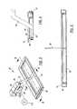
- FIG. 1is an exploded isometric view of an enclosure having a backup DC vent system.
- FIG. 2is a diagrammatic view of air flow paths through the enclosure when the DC vent system is operating.
- FIG. 3is an isometric view of a closed air intake system.
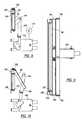
- FIG. 4is an enlarged sectional side elevation view of the air intake system taken along line 4 — 4 of FIG. 3 .
- FIG. 5is an enlarged sectional front elevation view of the air intake system taken along line 5 — 5 of FIG. 3 .
- FIG. 6is a sectional side elevation view similar to that shown in FIG. 4 but showing the air intake system in an open position.
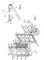
- FIG. 7is an exploded isometric view of a closed air exhaust system.
- FIG. 8is an enlarged sectional side elevation view taken along line 8 — 8 of FIG. 7 .
- FIG. 9is an enlarged sectional front elevation view taken along line 9 — 9 of FIG. 7 .
- FIG. 10is a sectional side elevation view similar to FIG. 8 but showing the air exhaust system in an open position.
- FIG. 11is a partially broken-away, diagrammatic, isometric view of an air distribution duct system.
- each cagehas a front door 16 , 18 and a rear door 20 , 22 .
- Beneath each cageis a battery compartment 24 , 26 which is open to ambient air through air intake louvers 27 , 28 .
- a top panel 29covers and insulates the cages.
- Each cagehas a floor panel, such as the floor panel 30 for the cage 12 and the floor panel 32 for the cage 14 .
- An air intake system 33including an opening 34 in the floor panel 30 , a movable door panel 35 to open and close the opening and an actuator 36 to move the door panel is configured to fit in the bottom of the cage 12 .
- a similar air intake system 37is configured for the cage 14 .
- the cage 12includes a left side 38 and the cage 14 includes a right side 39 .
- the cagesare sealed together in a side by side arrangement.
- a side cabinet 44is mounted to the right side 39 and an air exhaust system 46 is mounted to the left side 38 .
- An air conditioning system 48is mounted to the front door 18 of the enclosure to provide a managed temperature for thr components mouted within the cages.
- the doors, side cabinet and air exhaust systemare all sealed to the cages to prevent contaminants and other harmful material from entering the interior of the cages. In this way, the enclosure provides a sealed environment for the components mounted within.
- FIG. 2illustrates in diagrammatic form the operation of the backup DC vent system. If the air conditioning system 48 is unable to cool the components sufficiently, due to very hot weather, a brown out or a black out, for example, the backup DC vent system will activate. Shown in FIG. 2 is an enclosure 49 formed of two cages 50 , 51 , each containing electrical components 52 , 53 to be cooled. The cages are mounted on top of battery compartments 54 , 55 and each has a set of louvers 56 , 57 . The air intake systems 33 , 37 are mounted above the battery compartments and the air exhaust system 46 is mounted on the left.
- Air distribution duct systems 59 , 60are mounted above the air intake systems 33 , 37 , respectively.
- Arrows 61 , 62 , 63 , 64 , 65illustrate an air flow path through the cage 50
- arrows 66 , 67 , 68 , 69 and 65illustrate an air flow path through the cage 51 .
- the backup DC vent air flowbegins.
- the air intake assemblyincludes a frame 70 which is connected to the floor panel 30 , FIG. 1 around the opening 34 .
- the air intake assemblyalso includes the movable door panel 35 which is pivoted to the frame by a hinge 74 .
- the actuator 36is mounted within the cage and is connected to the panel door 35 by first, second and third links 78 , 80 , 82 .
- the linksare pivoted to each other and the third link 82 is rotated by the actuator.
- the actuatorcauses the panel to move between a closed position shown in FIGS. 3, 4 , and 5 and an open position shown in FIG. 6 .
- the frame 70includes a depending flange 84 to which is mounted a continuous bulb seal 86 .
- the actuatormaintains a pressure of about 35 inch/pounds whereby the door panel squeezes the seal by about a third to insure that the interior of the enclosure is kept air tight.
- FIGS. 1 and 7the air exhaust system 46 is shown in left and right facing exploded views.
- a fan box 90having a wall 91 .
- Attached to the inside of the wall 91are three door panels 92 , 94 , 96 , corresponding frames 98 , 100 , 102 and an actuator 104 .
- Attached to the outside of the wall 91are six fans 106 , 108 , 110 , 112 , 114 , 116 , eight baffles of which four baffles 118 , 120 , 122 , 124 are shown clearly and a fan mounting structure 126 . Covering the fans, baffles and mounting structure is a cover 130 .
- the cover 130has a shield wall 131 and six lateral openings of which three openings 132 , 133 , 134 are shown on a lateral wall 135 . Similar openings may be arranged on the opposite lateral wall 136 . Clamping devices, such as the clamp 138 , are provided to attach screens (not shown) over the openings to prevent insects and other contaminants from entering the fan box or the interior space of the enclosure.
- the shield wall 131 of the cover and the bafflesprevent wind driven rain and other contaminants from impinging directly upon the fans.
- wind driven raineven of hurricane velocity, which might normally impinge upon the fans is prevented from doing so.
- the ambient windis perpendicular to the lateral openings, it will pass through the openings in both lateral walls and not create an undesirable pressure drop or force contaminants through the fan into the enclosure.
- a drain opening 142is provided in a bottom wall 144 of the cover so that any wind driven rain entering the fan cover will drain away.
- the fan boxincludes six fan openings 150 , 152 , 154 , 156 , 158 , 160 adjacent to the six fans on one side of the wall 91 and the three frame/door panels on the other side.
- a direct air flow pathis formed from the interior of the enclosure, past the door panels, through the fan openings, past the fans and out of the lateral openings of the cover.
- FIGS. 8, 9 and 10a frame, a door panel and the actuator for the air exhaust system are shown in more detail.
- the frame 102is attached to the inside of the wall 91 FIG. 7 of the fan box 90 adjacent the openings 158 , 160 .
- the door panel 96is connected to the frame by a hinge 153 .
- the frameincludes an extending flange 155 .
- a continuous bulb seal 157extends around the flange and is squeezed by the door panel when the door panel is closed as shown in FIGS. 8 and 9, so that an air tight seal is provided.
- the actuator 104is connected to links 162 , 164 as shown, enabling the door panel to be moved between open and closed positions.
- the open positionis illustrated in FIG. 10 .
- Additional links 163 , 165 , 167 , 169 , FIG. 7,are provided to move the door panels 92 , 94 at the same time as the door panel 96 is moved by the actuator.
- the bulb sealrequires approximately 35 inch-pounds of pressure to compress approximately 33 percent.
- a control 170having sensors and a processor is mounted within the enclosure to control the fans and all of the door panels.
- Power for the control, the fans and the actuatorscome from either an internal rectified source or batteries in the battery compartments.
- the controlactivates the fans and the actuators in the event of a power loss and high temperature or an air conditioning failure and high temperatures. In this manner the temperature within the enclosure will remain relatively close to the ambient temperature, within 5-7° C., and this may be accomplished without unnecessarily exposing the components within the enclosure to high risks of humidity, water and dust.
- the air distribution duct system 59is shown in more detail.
- the systemincludes a receptacle 180 having a top wall 182 , a bottom wall 184 , a first side wall 186 , a second side wall 188 , a rear wall 190 and a front opening 192 .
- a first vent 194is formed in the side wall 186 , a second vent 196 in the side wall 188 and a third vent 198 in the rear wall 190 .
- a fourth vent 200is formed in the top wall 182 .
- Internal adjustable vanes 202are positioned in the front opening 192 to direct air to the four vents.
- a depending flap 204 in the top wallalso helps direct air to the fourth vent 200 .
- the receptaclealso is positioned over the door panel 35 , FIG. 1 of the air intake system 33 .
- the air distribution systemreceives air from the air conditioning system or the backup DC vent system, or perhaps both in brown out conditions, for predetermined air direction to efficiently and effectively direct cooling air to the components in the enclosure to be cooled.
- the air flow distributionis shown with a series of arrows.
- the arrow 210represents intake air from the air conditioning unit or from the air intake system of the backup DC vent system.
- the air distribution systemoperates whether the enclosure is being cooled by the air conditioning system or whether the backup system is being used.
- the internal vanes and the flapdirect the intake air to the side and rear vents and to the top vent in a predetermined manner.
- the exiting air from the side ventsis illustrated by the arrows 212 , 214
- the exiting air from the rear ventis illustrated by the arrow 216
- the exiting air from the top ventis illustrated by the arrow 218 .
- the backup DC vent systemis, under normal circumstances, closed and sealed thereby protecting the components in the interior of the enclosure in the same way the front and rear doors seal the interior of the enclosure. It is well known that enclosures are built to seal the sensitive electronic components within the enclosure from detrimental environmental elements such as high humidity, salt fog, contamination, rain borne water, dust and the like.
- the door panels of the backup DC vent systemopen only when a predetermined condition is reached and even then, the interior of the enclosure is well protected from contamination because of the placement of the air intake system and the use of the cover 130 . This is true even under high wind conditions.
- the backup DC vent systemis relatively inexpensive, reliable and relatively simple. Further, the backup DC vent system uses little power, little space, and does not detract from the typical use of the equipment enclosures. Yet the system protects the enclosure interior in a usual way when not activated.
- the backup DC vent systemis also modular in that as extra cage space may be added to an enclosure without difficulty. When a new cage is added, another air intake system is placed in the floor panel and another set of fans is added to the fan box, if needed. Furthermore, the backup DC vent system obviates the need for an expensive backup air conditioning system. Also, in the event that DC power is lost during use of the backup DC vent system, springs (not shown) in the actuators will return the door panels to their closed position in less than 30seconds. This ensures that the backup DC vent system will never remain open when not actually in use.
- the systemmay be monitored and programmed by the control to actuate a heater at 63° F. and a low temperature alarm at 60° F.
- the equipmentmay be shut down and an alarm sent. Going up the temperature scale, the equipment heater may be turned off at 77° F. and at 85° F. the air conditioning system switched on.
- a high temperature alarmmay be sent and at 105° F. the backup DC vent system activates and an alarm is sent.
- the equipmentmay be shut down and another alarm sent.
- the backup DC vent systemcloses all door panels.
Landscapes
- Engineering & Computer Science (AREA)
- Microelectronics & Electronic Packaging (AREA)
- Physics & Mathematics (AREA)
- Thermal Sciences (AREA)
- Computer Hardware Design (AREA)
- General Engineering & Computer Science (AREA)
- Ventilation (AREA)
- Cooling Or The Like Of Electrical Apparatus (AREA)
Abstract
Description
Claims (15)
Priority Applications (3)
| Application Number | Priority Date | Filing Date | Title |
|---|---|---|---|
| US10/038,637US6579168B1 (en) | 2002-01-03 | 2002-01-03 | Back-up DC vent system for equipment enclosure |
| CA002415526ACA2415526C (en) | 2002-01-03 | 2003-01-03 | Back-up dc vent system for equipment enclosure |
| MXPA03000096AMXPA03000096A (en) | 2002-01-03 | 2003-01-07 | Back-up dc vent system for equipment enclosure. |
Applications Claiming Priority (1)
| Application Number | Priority Date | Filing Date | Title |
|---|---|---|---|
| US10/038,637US6579168B1 (en) | 2002-01-03 | 2002-01-03 | Back-up DC vent system for equipment enclosure |
Publications (2)
| Publication Number | Publication Date |
|---|---|
| US6579168B1true US6579168B1 (en) | 2003-06-17 |
| US20030124970A1 US20030124970A1 (en) | 2003-07-03 |
Family
ID=21901039
Family Applications (1)
| Application Number | Title | Priority Date | Filing Date |
|---|---|---|---|
| US10/038,637Expired - LifetimeUS6579168B1 (en) | 2002-01-03 | 2002-01-03 | Back-up DC vent system for equipment enclosure |
Country Status (3)
| Country | Link |
|---|---|
| US (1) | US6579168B1 (en) |
| CA (1) | CA2415526C (en) |
| MX (1) | MXPA03000096A (en) |
Cited By (36)
| Publication number | Priority date | Publication date | Assignee | Title |
|---|---|---|---|---|
| US20030050002A1 (en)* | 2001-09-12 | 2003-03-13 | Steven Pfister | Ventilated outdoor electronics enclosure |
| US6710240B1 (en)* | 2003-04-24 | 2004-03-23 | Datech Technology Co., Ltd. | Register incorporating a toggle-joint mechanism between open and closed position |
| US20050063155A1 (en)* | 2003-09-19 | 2005-03-24 | Ryoichi Endo | Electronic apparatus |
| US20050252672A1 (en)* | 2003-10-14 | 2005-11-17 | Toshiba International Corporation | Apparatus for continuous cooling of electrical powered equipment |
| EP1602474A1 (en)* | 2004-06-03 | 2005-12-07 | Fette GmbH | Switchgear cabinet for tablet press |
| US20050286225A1 (en)* | 2004-04-26 | 2005-12-29 | Moore Robby J | Fire resistant, forced air cooled enclosure for computer digital data storage device |
| US20060056142A1 (en)* | 2004-09-10 | 2006-03-16 | Fumikazu Takahashi | Data processing unit and DC backup power supply |
| US20060276938A1 (en)* | 2005-06-06 | 2006-12-07 | Equinox Energy Solutions, Inc. | Optimized energy management system |
| US20060285291A1 (en)* | 2005-06-20 | 2006-12-21 | Jin Elkins | Electromagnet-assisted ventilation cover for an electronic equipment enclosure |
| US20070012473A1 (en)* | 2005-07-18 | 2007-01-18 | Thomas & Betts International, Inc. | Protective cover and system for electrical enclosures |
| US20070030650A1 (en)* | 2005-08-04 | 2007-02-08 | Liebert Corporation | Electronic equipment cabinet with integrated, high capacity, cooling system, and backup ventiliation |
| US20070105493A1 (en)* | 2003-08-04 | 2007-05-10 | Dennis Hill | Circulation and external venting unit |
| US20070273543A1 (en)* | 2003-03-24 | 2007-11-29 | Uglietto Salvatore R | Tech edge alert prevents mold |
| US20080101041A1 (en)* | 2006-10-26 | 2008-05-01 | Delta Electronics, Inc. | Electronic device having water-repellent structure and draining structure |
| US20080170363A1 (en)* | 2007-01-12 | 2008-07-17 | Hon Hai Precision Industry Co., Ltd. | Computer case |
| US20080212280A1 (en)* | 2007-03-01 | 2008-09-04 | Nec Corporation | Electronic apparatus |
| US20090117843A1 (en)* | 2007-11-02 | 2009-05-07 | Ice Qube, Inc. | Cooling apparatus and method |
| US20090213544A1 (en)* | 2008-02-27 | 2009-08-27 | International Business Machines Corporation | Variable position dampers for controlling air flow to multiple modules in a common chassis |
| US20090237881A1 (en)* | 2008-03-19 | 2009-09-24 | Harris Scott C | Cooling system for a portable device |
| US20090268391A1 (en)* | 2008-04-28 | 2009-10-29 | Hitachi. Ltd | Disk array device and electronic device |
| US20100127502A1 (en)* | 2008-07-28 | 2010-05-27 | Takashi Uchino | Wind turbine generator system |
| US20110085300A1 (en)* | 2009-10-14 | 2011-04-14 | Sivanandan Deepak Kumar | Communications cabinet with projectile resistant vents |
| US20110103009A1 (en)* | 2008-06-02 | 2011-05-05 | Audrey Julien-Roux | Computer bay cooling device and computer equipment comprising same |
| US8103389B2 (en) | 2006-05-18 | 2012-01-24 | Gridpoint, Inc. | Modular energy control system |
| US20120037353A1 (en)* | 2010-08-13 | 2012-02-16 | American Power Conversion Corporation | Single rack cold air containment |
| US20120242206A1 (en)* | 2011-03-22 | 2012-09-27 | Erwin Gasser | Shelter |
| US20120291990A1 (en)* | 2011-05-16 | 2012-11-22 | Huawei Technologies Co., Ltd. | Heat dissipation apparatus and outdoor communication device |
| US20130213617A1 (en)* | 2012-02-21 | 2013-08-22 | Wistron Corporation | Heat dissipating mechanism adapted to an electronic device and electronic device therewith |
| US9004995B1 (en) | 2004-08-02 | 2015-04-14 | Bard Manufacturing Company | Wall curb for air treatment system |
| US20160234963A1 (en)* | 2015-02-10 | 2016-08-11 | Emerson Network Power, Energy Systems, North America, Inc. | Enclosures and methods for removing hydrogen gas from enclosures |
| US20160286691A1 (en)* | 2009-11-30 | 2016-09-29 | Emerson Network Power, Energy Systems, North America, Inc. | Outdoor electronic equipment enclosures and related methods |
| US10334759B2 (en) | 2013-11-26 | 2019-06-25 | Panduit Corp. | Universal inlet duct system for side air intake equipment |
| US10451295B2 (en) | 2014-12-22 | 2019-10-22 | Diversified Control, Inc. | Equipment enclosure with multi-mode temperature control system |
| US10893632B2 (en) | 2017-05-12 | 2021-01-12 | Diversified Control, Inc. | Equipment enclosure free-air cooling assembly with indexing pre-screen |
| CN113079659A (en)* | 2021-05-21 | 2021-07-06 | 周平 | Automatic change control instrument cabinet |
| CN113347826A (en)* | 2021-05-28 | 2021-09-03 | 杭州首瑞科技有限公司 | Photoelectric integrated box |
Families Citing this family (6)
| Publication number | Priority date | Publication date | Assignee | Title |
|---|---|---|---|---|
| WO2005021376A2 (en)* | 2003-08-27 | 2005-03-10 | Purcell Systems, Inc. | Internal environmental control system and uses thereof |
| JP4778246B2 (en)* | 2005-03-16 | 2011-09-21 | 日本電気株式会社 | Wireless base station equipment |
| JP4282677B2 (en)* | 2006-03-09 | 2009-06-24 | 株式会社東芝 | Transmitter |
| US20090239460A1 (en)* | 2006-04-27 | 2009-09-24 | Wright Line, Llc | Assembly for Extracting Heat from a Housing for Electronic Equipment |
| EP2724598B1 (en)* | 2011-06-27 | 2017-05-17 | Henkel IP & Holding GmbH | Cooling module with parallel blowers |
| CN109617165A (en)* | 2018-12-20 | 2019-04-12 | 天津天地伟业信息系统集成有限公司 | A kind of gunlock power supply for the continuation of the journey that has a power failure |
Citations (7)
| Publication number | Priority date | Publication date | Assignee | Title |
|---|---|---|---|---|
| US5479341A (en)* | 1994-04-21 | 1995-12-26 | Pihl; Lawrence E. | Electronic data security apparatus |
| US5485878A (en) | 1993-02-05 | 1996-01-23 | Bard Manufacturing Company | Modular air conditioning system |
| US6000623A (en)* | 1998-01-15 | 1999-12-14 | International Business Machines Corporation | System packaging for high performance computer applications |
| US6105875A (en) | 1998-09-08 | 2000-08-22 | Lucent Technologies, Inc. | Direct air cooling of outdoor electronic cabinets |
| US6164369A (en)* | 1999-07-13 | 2000-12-26 | Lucent Technologies Inc. | Door mounted heat exchanger for outdoor equipment enclosure |
| US6181557B1 (en) | 1999-10-29 | 2001-01-30 | Motorola, Inc. | Electronic component, method of cooling, and damper therefor |
| US6453378B1 (en)* | 1998-12-16 | 2002-09-17 | Gateway, Inc. | Portable computer with enhanced performance management |
- 2002
- 2002-01-03USUS10/038,637patent/US6579168B1/ennot_activeExpired - Lifetime
- 2003
- 2003-01-03CACA002415526Apatent/CA2415526C/ennot_activeExpired - Lifetime
- 2003-01-07MXMXPA03000096Apatent/MXPA03000096A/enactiveIP Right Grant
Patent Citations (7)
| Publication number | Priority date | Publication date | Assignee | Title |
|---|---|---|---|---|
| US5485878A (en) | 1993-02-05 | 1996-01-23 | Bard Manufacturing Company | Modular air conditioning system |
| US5479341A (en)* | 1994-04-21 | 1995-12-26 | Pihl; Lawrence E. | Electronic data security apparatus |
| US6000623A (en)* | 1998-01-15 | 1999-12-14 | International Business Machines Corporation | System packaging for high performance computer applications |
| US6105875A (en) | 1998-09-08 | 2000-08-22 | Lucent Technologies, Inc. | Direct air cooling of outdoor electronic cabinets |
| US6453378B1 (en)* | 1998-12-16 | 2002-09-17 | Gateway, Inc. | Portable computer with enhanced performance management |
| US6164369A (en)* | 1999-07-13 | 2000-12-26 | Lucent Technologies Inc. | Door mounted heat exchanger for outdoor equipment enclosure |
| US6181557B1 (en) | 1999-10-29 | 2001-01-30 | Motorola, Inc. | Electronic component, method of cooling, and damper therefor |
Cited By (67)
| Publication number | Priority date | Publication date | Assignee | Title |
|---|---|---|---|---|
| US6749498B2 (en)* | 2001-09-12 | 2004-06-15 | Arris International, Inc. | Ventilated outdoor electronics enclosure |
| US20030050002A1 (en)* | 2001-09-12 | 2003-03-13 | Steven Pfister | Ventilated outdoor electronics enclosure |
| US20070273543A1 (en)* | 2003-03-24 | 2007-11-29 | Uglietto Salvatore R | Tech edge alert prevents mold |
| US6710240B1 (en)* | 2003-04-24 | 2004-03-23 | Datech Technology Co., Ltd. | Register incorporating a toggle-joint mechanism between open and closed position |
| US20070105493A1 (en)* | 2003-08-04 | 2007-05-10 | Dennis Hill | Circulation and external venting unit |
| US7604534B2 (en) | 2003-08-04 | 2009-10-20 | Rayhill Limited | Circulation and external venting unit |
| US20050063155A1 (en)* | 2003-09-19 | 2005-03-24 | Ryoichi Endo | Electronic apparatus |
| US6958909B2 (en)* | 2003-09-19 | 2005-10-25 | Matsushita Electric Industrial Co., Ltd. | Electronic apparatus |
| US20050252672A1 (en)* | 2003-10-14 | 2005-11-17 | Toshiba International Corporation | Apparatus for continuous cooling of electrical powered equipment |
| US7432819B2 (en)* | 2003-10-14 | 2008-10-07 | Toshiba International Corporation | Apparatus for continuous cooling of electrical powered equipment |
| AU2005237513B2 (en)* | 2004-04-26 | 2009-02-26 | Auburn I.P. Holdings, Llc | Fire resistant, forced air cooled enclosure for computer digital data storage device |
| WO2005104707A3 (en)* | 2004-04-26 | 2006-03-30 | Robby Jay Moore | Fire resistant, forced air cooled enclosure for computer digital data storage device |
| US20050286225A1 (en)* | 2004-04-26 | 2005-12-29 | Moore Robby J | Fire resistant, forced air cooled enclosure for computer digital data storage device |
| US7211742B2 (en)* | 2004-04-26 | 2007-05-01 | Auburn I.P. Holdings, Llc | Fire resistant, forced air cooled enclosure for computer digital data storage device |
| EP1602474A1 (en)* | 2004-06-03 | 2005-12-07 | Fette GmbH | Switchgear cabinet for tablet press |
| US9004995B1 (en) | 2004-08-02 | 2015-04-14 | Bard Manufacturing Company | Wall curb for air treatment system |
| US7589436B2 (en)* | 2004-09-10 | 2009-09-15 | Hitachi Computer Peripherals Co., Ltd. | Data processing unit and DC backup power supply |
| US20060056142A1 (en)* | 2004-09-10 | 2006-03-16 | Fumikazu Takahashi | Data processing unit and DC backup power supply |
| US20060276938A1 (en)* | 2005-06-06 | 2006-12-07 | Equinox Energy Solutions, Inc. | Optimized energy management system |
| US7274975B2 (en) | 2005-06-06 | 2007-09-25 | Gridpoint, Inc. | Optimized energy management system |
| US7783390B2 (en) | 2005-06-06 | 2010-08-24 | Gridpoint, Inc. | Method for deferring demand for electrical energy |
| US20060285291A1 (en)* | 2005-06-20 | 2006-12-21 | Jin Elkins | Electromagnet-assisted ventilation cover for an electronic equipment enclosure |
| US7345875B2 (en)* | 2005-06-20 | 2008-03-18 | Emerson Network Power, Energy Systems, North America, Inc. | Electromagnet-assisted ventilation cover for an electronic equipment enclosure |
| US20070012473A1 (en)* | 2005-07-18 | 2007-01-18 | Thomas & Betts International, Inc. | Protective cover and system for electrical enclosures |
| US7170010B1 (en) | 2005-07-18 | 2007-01-30 | Thomas & Betts International, Inc. | Protective cover and system for electrical enclosures |
| US7788940B2 (en)* | 2005-08-04 | 2010-09-07 | Liebert Corporation | Electronic equipment cabinet with integrated, high capacity, cooling system, and backup ventilation |
| US20070030650A1 (en)* | 2005-08-04 | 2007-02-08 | Liebert Corporation | Electronic equipment cabinet with integrated, high capacity, cooling system, and backup ventiliation |
| US8103389B2 (en) | 2006-05-18 | 2012-01-24 | Gridpoint, Inc. | Modular energy control system |
| US20080101041A1 (en)* | 2006-10-26 | 2008-05-01 | Delta Electronics, Inc. | Electronic device having water-repellent structure and draining structure |
| US20080170363A1 (en)* | 2007-01-12 | 2008-07-17 | Hon Hai Precision Industry Co., Ltd. | Computer case |
| US7542275B2 (en)* | 2007-01-12 | 2009-06-02 | Hon Hai Precision Industry Co., Ltd. | Computer case |
| US7583501B2 (en)* | 2007-03-01 | 2009-09-01 | Nec Corporation | Electronic apparatus |
| US20080212280A1 (en)* | 2007-03-01 | 2008-09-04 | Nec Corporation | Electronic apparatus |
| US20090117843A1 (en)* | 2007-11-02 | 2009-05-07 | Ice Qube, Inc. | Cooling apparatus and method |
| US8070569B2 (en) | 2007-11-02 | 2011-12-06 | Ice Qube, Inc. | Cooling apparatus and method |
| US7599183B2 (en)* | 2008-02-27 | 2009-10-06 | International Business Machines Corporation | Variable position dampers for controlling air flow to multiple modules in a common chassis |
| US20090213544A1 (en)* | 2008-02-27 | 2009-08-27 | International Business Machines Corporation | Variable position dampers for controlling air flow to multiple modules in a common chassis |
| US20090237881A1 (en)* | 2008-03-19 | 2009-09-24 | Harris Scott C | Cooling system for a portable device |
| US20110045866A1 (en)* | 2008-03-19 | 2011-02-24 | Harris Technology, Llc | Cooling System for a Portable Device |
| US8730664B1 (en) | 2008-03-19 | 2014-05-20 | Harris Technology, Llc | Cooling system for a portable device |
| US7782613B2 (en)* | 2008-03-19 | 2010-08-24 | Harris Technology, Llc | Cooling system for a portable device |
| US8085537B2 (en) | 2008-03-19 | 2011-12-27 | Harris Technology, Llc | Cooling system for a portable device |
| US7872865B2 (en)* | 2008-04-28 | 2011-01-18 | Hitachi, Ltd. | Disk array device and electronic device |
| US20090268391A1 (en)* | 2008-04-28 | 2009-10-29 | Hitachi. Ltd | Disk array device and electronic device |
| US8587941B2 (en)* | 2008-06-02 | 2013-11-19 | Bull Sas | Computer bay cooling device and computer equipment comprising same |
| US20110103009A1 (en)* | 2008-06-02 | 2011-05-05 | Audrey Julien-Roux | Computer bay cooling device and computer equipment comprising same |
| US9066452B2 (en) | 2008-06-02 | 2015-06-23 | Bull Sas | Computer bay cooling device and computer equipment comprising same |
| US8109814B2 (en)* | 2008-07-28 | 2012-02-07 | Mitsubishi Heavy Industries, Ltd. | Wind turbine generator system |
| US20100127502A1 (en)* | 2008-07-28 | 2010-05-27 | Takashi Uchino | Wind turbine generator system |
| US8279602B2 (en)* | 2009-10-14 | 2012-10-02 | Commscope, Inc. | Communications cabinet with projectile resistant vents |
| US20110085300A1 (en)* | 2009-10-14 | 2011-04-14 | Sivanandan Deepak Kumar | Communications cabinet with projectile resistant vents |
| US20160286691A1 (en)* | 2009-11-30 | 2016-09-29 | Emerson Network Power, Energy Systems, North America, Inc. | Outdoor electronic equipment enclosures and related methods |
| US20120037353A1 (en)* | 2010-08-13 | 2012-02-16 | American Power Conversion Corporation | Single rack cold air containment |
| US8961278B2 (en)* | 2010-08-13 | 2015-02-24 | Schneider Electric It Corporation | Single rack cold air containment |
| US20120242206A1 (en)* | 2011-03-22 | 2012-09-27 | Erwin Gasser | Shelter |
| US8939524B2 (en)* | 2011-03-22 | 2015-01-27 | Erwin Gasser | Shelter |
| US20120291990A1 (en)* | 2011-05-16 | 2012-11-22 | Huawei Technologies Co., Ltd. | Heat dissipation apparatus and outdoor communication device |
| US20130213617A1 (en)* | 2012-02-21 | 2013-08-22 | Wistron Corporation | Heat dissipating mechanism adapted to an electronic device and electronic device therewith |
| US9103606B2 (en)* | 2012-02-21 | 2015-08-11 | Wistron Corporation | Heat dissipating mechanism adapted to an electronic device and electronic device therewith |
| US10334759B2 (en) | 2013-11-26 | 2019-06-25 | Panduit Corp. | Universal inlet duct system for side air intake equipment |
| US11304339B2 (en) | 2013-11-26 | 2022-04-12 | Panduit Corp. | Universal inlet duct system for side air intake equipment |
| US10451295B2 (en) | 2014-12-22 | 2019-10-22 | Diversified Control, Inc. | Equipment enclosure with multi-mode temperature control system |
| US20160234963A1 (en)* | 2015-02-10 | 2016-08-11 | Emerson Network Power, Energy Systems, North America, Inc. | Enclosures and methods for removing hydrogen gas from enclosures |
| US10893632B2 (en) | 2017-05-12 | 2021-01-12 | Diversified Control, Inc. | Equipment enclosure free-air cooling assembly with indexing pre-screen |
| CN113079659A (en)* | 2021-05-21 | 2021-07-06 | 周平 | Automatic change control instrument cabinet |
| CN113347826A (en)* | 2021-05-28 | 2021-09-03 | 杭州首瑞科技有限公司 | Photoelectric integrated box |
| CN113347826B (en)* | 2021-05-28 | 2022-06-24 | 杭州首瑞科技有限公司 | Photoelectric integrated box |
Also Published As
| Publication number | Publication date |
|---|---|
| MXPA03000096A (en) | 2004-07-16 |
| US20030124970A1 (en) | 2003-07-03 |
| CA2415526A1 (en) | 2003-07-03 |
| CA2415526C (en) | 2006-05-30 |
Similar Documents
| Publication | Publication Date | Title |
|---|---|---|
| US6579168B1 (en) | Back-up DC vent system for equipment enclosure | |
| US7974094B2 (en) | Outside plant telecommunications cabinet direct air cooling system | |
| WO2011047116A1 (en) | Outdoor communication cabinet including fan tray and filter and projectile resistant vents and method of detecting blockage of communication cabinet filter | |
| US6345511B1 (en) | Air handling apparatus | |
| US6775137B2 (en) | Method and apparatus for combined air and liquid cooling of stacked electronics components | |
| AU2004301898B2 (en) | Circulation and external venting unit | |
| KR101468874B1 (en) | The emergency protection apparatus of the server rack | |
| US20080068798A1 (en) | Outside plant cabinet thermal system | |
| EP0838639B1 (en) | Apparatus for installing a ventilation fan | |
| US11573021B2 (en) | Multi-component whole house fan system | |
| CA2578458C (en) | Self contained heating/cooling roof top unit with built in independent pressure relief | |
| US6542361B2 (en) | System for cooling computer components housed within a computer casing | |
| CN108105929A (en) | A kind of prefabricated cabin | |
| CA3221286A1 (en) | Systems and methods for cooling in power distribution centers | |
| CN219959765U (en) | Dampproofing block terminal | |
| US10098255B2 (en) | Vent control apparatus and method | |
| CN218061646U (en) | Energy storage container | |
| CN216134123U (en) | Electric element protection shell used in electric cabinet | |
| CN115045537A (en) | an energy storage container | |
| JP2586791Y2 (en) | Cooling device for electronic equipment housing | |
| JP3125092B2 (en) | Floor-mounted fan coil unit | |
| JP3872729B2 (en) | Switchgear | |
| US4478138A (en) | Supplemental cooling system | |
| KR20160029413A (en) | Ventilation Device for a Display of an Elevator Hall Door | |
| TWM550013U (en) | Power control box of renewable energy |
Legal Events
| Date | Code | Title | Description |
|---|---|---|---|
| AS | Assignment | Owner name:MARCONI COMMUNICATIONS, INC., OHIO Free format text:ASSIGNMENT OF ASSIGNORS INTEREST;ASSIGNORS:WEBSTER, JAMES W.;GARCIA, MARVIN P.;REEL/FRAME:012624/0212 Effective date:20020125 | |
| STCF | Information on status: patent grant | Free format text:PATENTED CASE | |
| AS | Assignment | Owner name:MARCONI INTELLECTUAL PROPERTY ( RINGFENCE) INC., P Free format text:ASSIGNMENT OF ASSIGNORS INTEREST;ASSIGNOR:MARCONI COMMUNICATIONS, INC.;REEL/FRAME:014675/0855 Effective date:20031028 | |
| AS | Assignment | Owner name:EMERSUB XCII, INC., MISSOURI Free format text:ASSIGNMENT OF ASSIGNORS INTEREST;ASSIGNOR:MARCONI INTELLECTUAL PROPERTY (RINGFENCE) INC.;REEL/FRAME:015394/0222 Effective date:20040812 | |
| AS | Assignment | Owner name:EMERSON NETWORK POWER, ENERGY SYSTEMS, NORTH AMERI Free format text:CHANGE OF NAME;ASSIGNOR:EMERSUB XCII, INC.;REEL/FRAME:015452/0663 Effective date:20041119 | |
| FPAY | Fee payment | Year of fee payment:4 | |
| FPAY | Fee payment | Year of fee payment:8 | |
| FPAY | Fee payment | Year of fee payment:12 | |
| AS | Assignment | Owner name:JPMORGAN CHASE BANK, N.A., AS COLLATERAL AGENT, NE Free format text:SECURITY AGREEMENT;ASSIGNORS:ALBER CORP.;ASCO POWER TECHNOLOGIES, L.P.;AVOCENT CORPORATION;AND OTHERS;REEL/FRAME:040783/0148 Effective date:20161130 Owner name:JPMORGAN CHASE BANK, N.A., AS COLLATERAL AGENT, NEW YORK Free format text:SECURITY AGREEMENT;ASSIGNORS:ALBER CORP.;ASCO POWER TECHNOLOGIES, L.P.;AVOCENT CORPORATION;AND OTHERS;REEL/FRAME:040783/0148 Effective date:20161130 | |
| AS | Assignment | Owner name:JPMORGAN CHASE BANK, N.A., AS COLLATERAL AGENT, NE Free format text:SECURITY AGREEMENT;ASSIGNORS:ALBER CORP.;ASCO POWER TECHNOLOGIES, L.P.;AVOCENT CORPORATION;AND OTHERS;REEL/FRAME:040797/0615 Effective date:20161130 Owner name:JPMORGAN CHASE BANK, N.A., AS COLLATERAL AGENT, NEW YORK Free format text:SECURITY AGREEMENT;ASSIGNORS:ALBER CORP.;ASCO POWER TECHNOLOGIES, L.P.;AVOCENT CORPORATION;AND OTHERS;REEL/FRAME:040797/0615 Effective date:20161130 | |
| AS | Assignment | Owner name:VERTIV ENERGY SYSTEMS, INC., ILLINOIS Free format text:CHANGE OF NAME;ASSIGNOR:EMERSON NETWORK POWER, ENERGY SYSTEMS, NORTH AMERICA, INC.;REEL/FRAME:042469/0671 Effective date:20170403 | |
| AS | Assignment | Owner name:THE BANK OF NEW YORK MELLON TRUST COMPANY, N.A., T Free format text:SECOND LIEN SECURITY AGREEMENT;ASSIGNORS:VERTIV IT SYSTEMS, INC.;VERTIV CORPORATION;VERTIV NORTH AMERICA, INC.;AND OTHERS;REEL/FRAME:049415/0262 Effective date:20190513 Owner name:THE BANK OF NEW YORK MELLON TRUST COMPANY, N.A., TEXAS Free format text:SECOND LIEN SECURITY AGREEMENT;ASSIGNORS:VERTIV IT SYSTEMS, INC.;VERTIV CORPORATION;VERTIV NORTH AMERICA, INC.;AND OTHERS;REEL/FRAME:049415/0262 Effective date:20190513 | |
| AS | Assignment | Owner name:VERTIV CORPORATION, OHIO Free format text:MERGER;ASSIGNOR:VERTIV ENERGY SYSTEMS, INC.;REEL/FRAME:051830/0692 Effective date:20191231 | |
| AS | Assignment | Owner name:VERTIV IT SYSTEMS, INC. (F/K/A AVOCENT FREMONT, LLC), OHIO Free format text:RELEASE BY SECURED PARTY;ASSIGNOR:JPMORGAN CHASE BANK, N.A.;REEL/FRAME:052065/0666 Effective date:20200302 Owner name:VERTIV IT SYSTEMS, INC. (F/K/A AVOCENT REDMOND CORP.), OHIO Free format text:RELEASE BY SECURED PARTY;ASSIGNOR:JPMORGAN CHASE BANK, N.A.;REEL/FRAME:052065/0666 Effective date:20200302 Owner name:VERTIV CORPORATION (F/K/A LIEBERT CORPORATION), OHIO Free format text:RELEASE BY SECURED PARTY;ASSIGNOR:JPMORGAN CHASE BANK, N.A.;REEL/FRAME:052065/0666 Effective date:20200302 Owner name:VERTIV IT SYSTEMS, INC. (F/K/A AVOCENT CORPORATION), OHIO Free format text:RELEASE BY SECURED PARTY;ASSIGNOR:JPMORGAN CHASE BANK, N.A.;REEL/FRAME:052065/0666 Effective date:20200302 Owner name:VERTIV CORPORATION (F/K/A EMERSON NETWORK POWER, ENERGY SYSTEMS, NORTH AMERICA, INC.), OHIO Free format text:RELEASE BY SECURED PARTY;ASSIGNOR:JPMORGAN CHASE BANK, N.A.;REEL/FRAME:052065/0666 Effective date:20200302 Owner name:VERTIV IT SYSTEMS, INC. (F/K/A AVOCENT HUNTSVILLE, LLC), OHIO Free format text:RELEASE BY SECURED PARTY;ASSIGNOR:JPMORGAN CHASE BANK, N.A.;REEL/FRAME:052065/0666 Effective date:20200302 Owner name:ELECTRICAL RELIABILITY SERVICES, INC., OHIO Free format text:RELEASE BY SECURED PARTY;ASSIGNOR:JPMORGAN CHASE BANK, N.A.;REEL/FRAME:052065/0666 Effective date:20200302 Owner name:VERTIV CORPORATION (F/K/A ALBER CORP.), OHIO Free format text:RELEASE BY SECURED PARTY;ASSIGNOR:JPMORGAN CHASE BANK, N.A.;REEL/FRAME:052065/0666 Effective date:20200302 Owner name:VERTIV CORPORATION, OHIO Free format text:RELEASE BY SECURED PARTY;ASSIGNOR:THE BANK OF NEW YORK MELLON TRUST COMPANY N.A.;REEL/FRAME:052071/0913 Effective date:20200302 Owner name:ELECTRICAL RELIABILITY SERVICES, INC., OHIO Free format text:RELEASE BY SECURED PARTY;ASSIGNOR:THE BANK OF NEW YORK MELLON TRUST COMPANY N.A.;REEL/FRAME:052071/0913 Effective date:20200302 Owner name:VERTIV IT SYSTEMS, INC., OHIO Free format text:RELEASE BY SECURED PARTY;ASSIGNOR:THE BANK OF NEW YORK MELLON TRUST COMPANY N.A.;REEL/FRAME:052071/0913 Effective date:20200302 | |
| AS | Assignment | Owner name:CITIBANK, N.A., NEW YORK Free format text:SECURITY AGREEMENT;ASSIGNORS:ELECTRICAL RELIABILITY SERVICES, INC.;ENERGY LABS, INC.;VERTIV CORPORATION;AND OTHERS;REEL/FRAME:052076/0874 Effective date:20200302 | |
| AS | Assignment | Owner name:UMB BANK, N.A., AS COLLATERAL AGENT, TEXAS Free format text:SECURITY INTEREST;ASSIGNORS:VERTIV CORPORATION;VERTIV IT SYSTEMS, INC.;ELECTRICAL RELIABILITY SERVICES, INC.;AND OTHERS;REEL/FRAME:057923/0782 Effective date:20211022 |