US6578967B1 - Mounting system for body mounted camera equipment and connector assemblies therefor - Google Patents
Mounting system for body mounted camera equipment and connector assemblies thereforDownload PDFInfo
- Publication number
- US6578967B1 US6578967B1US09/809,536US80953601AUS6578967B1US 6578967 B1US6578967 B1US 6578967B1US 80953601 AUS80953601 AUS 80953601AUS 6578967 B1US6578967 B1US 6578967B1
- Authority
- US
- United States
- Prior art keywords
- axial
- connector
- connectors
- pins
- engagement
- Prior art date
- Legal status (The legal status is an assumption and is not a legal conclusion. Google has not performed a legal analysis and makes no representation as to the accuracy of the status listed.)
- Expired - Fee Related
Links
- 230000000712assemblyEffects0.000titleabstractdescription5
- 238000000429assemblyMethods0.000titleabstractdescription5
- 230000013011matingEffects0.000claimsabstractdescription10
- 230000033001locomotionEffects0.000abstractdescription6
- 230000008878couplingEffects0.000description4
- 238000010168coupling processMethods0.000description4
- 238000005859coupling reactionMethods0.000description4
- 240000005020Acaciella glaucaSpecies0.000description2
- 235000003499redwoodNutrition0.000description2
- 238000006073displacement reactionMethods0.000description1
- 230000000694effectsEffects0.000description1
- 238000000605extractionMethods0.000description1
- 230000001788irregularEffects0.000description1
- 230000014759maintenance of locationEffects0.000description1
- 230000004048modificationEffects0.000description1
- 238000012986modificationMethods0.000description1
- 230000000717retained effectEffects0.000description1
Images


Classifications
- F—MECHANICAL ENGINEERING; LIGHTING; HEATING; WEAPONS; BLASTING
- F16—ENGINEERING ELEMENTS AND UNITS; GENERAL MEASURES FOR PRODUCING AND MAINTAINING EFFECTIVE FUNCTIONING OF MACHINES OR INSTALLATIONS; THERMAL INSULATION IN GENERAL
- F16M—FRAMES, CASINGS OR BEDS OF ENGINES, MACHINES OR APPARATUS, NOT SPECIFIC TO ENGINES, MACHINES OR APPARATUS PROVIDED FOR ELSEWHERE; STANDS; SUPPORTS
- F16M13/00—Other supports for positioning apparatus or articles; Means for steadying hand-held apparatus or articles
- F16M13/04—Other supports for positioning apparatus or articles; Means for steadying hand-held apparatus or articles for supporting on, or holding steady relative to, a person, e.g. by chains, e.g. rifle butt or pistol grip supports, supports attached to the chest or head
- F—MECHANICAL ENGINEERING; LIGHTING; HEATING; WEAPONS; BLASTING
- F16—ENGINEERING ELEMENTS AND UNITS; GENERAL MEASURES FOR PRODUCING AND MAINTAINING EFFECTIVE FUNCTIONING OF MACHINES OR INSTALLATIONS; THERMAL INSULATION IN GENERAL
- F16M—FRAMES, CASINGS OR BEDS OF ENGINES, MACHINES OR APPARATUS, NOT SPECIFIC TO ENGINES, MACHINES OR APPARATUS PROVIDED FOR ELSEWHERE; STANDS; SUPPORTS
- F16M11/00—Stands or trestles as supports for apparatus or articles placed thereon ; Stands for scientific apparatus such as gravitational force meters
- F16M11/02—Heads
- F16M11/16—Details concerning attachment of head-supporting legs, with or without actuation of locking members thereof
- F—MECHANICAL ENGINEERING; LIGHTING; HEATING; WEAPONS; BLASTING
- F16—ENGINEERING ELEMENTS AND UNITS; GENERAL MEASURES FOR PRODUCING AND MAINTAINING EFFECTIVE FUNCTIONING OF MACHINES OR INSTALLATIONS; THERMAL INSULATION IN GENERAL
- F16M—FRAMES, CASINGS OR BEDS OF ENGINES, MACHINES OR APPARATUS, NOT SPECIFIC TO ENGINES, MACHINES OR APPARATUS PROVIDED FOR ELSEWHERE; STANDS; SUPPORTS
- F16M11/00—Stands or trestles as supports for apparatus or articles placed thereon ; Stands for scientific apparatus such as gravitational force meters
- F16M11/20—Undercarriages with or without wheels
- F16M11/2007—Undercarriages with or without wheels comprising means allowing pivoting adjustment
- F16M11/2035—Undercarriages with or without wheels comprising means allowing pivoting adjustment in more than one direction
- F16M11/2042—Undercarriages with or without wheels comprising means allowing pivoting adjustment in more than one direction constituted of several dependent joints
- F16M11/205—Undercarriages with or without wheels comprising means allowing pivoting adjustment in more than one direction constituted of several dependent joints the axis of rotation intersecting in a single point, e.g. gimbals
- F—MECHANICAL ENGINEERING; LIGHTING; HEATING; WEAPONS; BLASTING
- F16—ENGINEERING ELEMENTS AND UNITS; GENERAL MEASURES FOR PRODUCING AND MAINTAINING EFFECTIVE FUNCTIONING OF MACHINES OR INSTALLATIONS; THERMAL INSULATION IN GENERAL
- F16M—FRAMES, CASINGS OR BEDS OF ENGINES, MACHINES OR APPARATUS, NOT SPECIFIC TO ENGINES, MACHINES OR APPARATUS PROVIDED FOR ELSEWHERE; STANDS; SUPPORTS
- F16M13/00—Other supports for positioning apparatus or articles; Means for steadying hand-held apparatus or articles
Definitions
- the field of the present inventionis rigid connector assemblies particularly adaptable for mounting systems used for body mounted camera equipment.
- the present inventionis directed to a connector assembly having two connectors which are axially engageable.
- a first couplingis provided by a cylindrical surface with grooves therein on the first connector cooperating with radial pins on the second connector.
- the connector assemblyfurther includes an angular interlock and an axial lock providing additional engagement.
- the coupling of the grooves and the radial pinsprovides a first engagement with the pins in an axial entry portion of the grooves, a second engagement with the pins in a circumferential portion of the grooves and a third engagement with the pins in an axial seating portion of the grooves.
- the angular interlock of the connector assemblyincludes two engaging surfaces, one on each connector. These engaging surfaces are arranged such that they remain disengaged until the third engagement of the connectors.
- the angular interlock of the first aspect of the present inventionincludes angularly spaced axial pins on one connector with axial sockets on the other.
- the pins and socketsmay include mating conical surfaces. Additionally, there may be three such pins to insure a planar engagement seat.
- the socketsmay be provided in the integer multiples of the three pins to provide additional angular flexibility of the connectors.
- the axial lock of the connector assemblyincludes a locking element which is a threaded locking ring rotatably and axially slidably mounted to one of the connectors with the other connector including a mating threaded surface for engagement with the locking element.
- the connector assemblyis incorporated with a mounting system for body mounted camera equipment.
- the connector assemblyis mounted to one end of a tube which is, in turn, mounted to a three-axis gimbal intermediate the ends.
- FIG. 1is an assembled perspective view of the connector assembly.
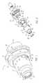
- FIG. 2is an exploded assembly view in perspective of the connector assembly of FIG. 1 .
- FIG. 3is an exploded assembly view in perspective of the connector assembly of FIG. 1 viewed from a different angle from that of FIG. 2 .
- FIG. 4is a cross-sectional view in perspective of a connector of the connector assembly of FIG. 1 .
- FIG. 5is a partially-exploded assembly view in perspective of a mounting system for body mounted camera equipment.
- FIG. 6is an assembled perspective view of the system of FIG. 5 .
- the connector assemblygenerally designated 10 , includes a first connector 12 .
- the connector 12is of generally circular cross sections normal to the axial centerline of a central passage 14 extending therethrough.
- the connector 12includes an attachment section 16 and a snap ring 24 to capture a conduit connector and prevent it from retracting axially inside the central passage 14 and into the tube of a mounting system.
- a snap ring groove 23may receive a snap ring 24 to provide a shoulder to prevent retraction of a conduit extending through the passage 14 and to be removable for disassembly.
- the main body of the connector 12includes a threaded outer surface 26 at the end opposite to that of the attachment section 16 .
- the central passage 14is cylindrical through the main body of the connector 12 .
- the cylindrical surface of the main body of the connector 12is able to fit within a tube of a mounting system.
- the raised threaded outer surface 26provides a shoulder for the mounting tube to abut against. Holes 27 accept fasteners to retain the mounting tube attached.
- Grooves, generally designated 28are cut into the cylindrical surface of the central passage 14 . Two grooves 28 are illustrated. Three or more may also be employed.
- the grooves 28may best be considered as including an axial entry portion 30 which extends to the end of the connector 12 .
- a circumferential portion 32extends circumferentially from the axial entry portion 30 .
- An axial seating portion 34extends axially further into the cylinder of the connector 12 at the opposite end of the circumferential portion 32 from that of the axial entry portion 30 .
- the axial entry portion 30extends in a first direction from the circumferential portion 32 to the end surface of the connector 12 while the axial seating portion 34 extends in the other direction further into the body of the connector 12 .
- a second connector 36is axially engageable with the first connector 12 .
- the second connector 36is also generally of circular cross section normal to a central passage 38 aligned with the central passage 14 when the two connectors 12 and 36 are engaged.
- a cylindrical attachment section 40is associated with a mounting flange 42 having holes 44 therethrough for receiving pins or fasteners associated with various attachments for body mounted camera equipment.
- a cylindrical central body 46 on the connector 36includes a snap ring groove 48 to retain a locking element described below.
- Axial holes 50are arranged about the shoulder 52 of the cylindrical central body 46 . These holes 50 receive axial pins described below.
- An insert 54extends axially from the cylindrical central body 46 of the connector 36 . This insert 54 mostly fits within the central passage 14 defined by the inner cylindrical surface of the connector 12 .
- the insert 54includes a cut away end profile to define lead-in fingers 56 to accommodate some axial misalignment when the connectors 12 and 36 are being assembled together.
- the lead-in fingers 56include radial holes 58 .
- Radial pins 60are fixed in the radial holes 58 and are aligned for engagement with the grooves 28 of the connector 12 .
- An angular interlockcooperates between the connectors 12 and 36 .
- this angular interlockincludes two engaging surfaces, one on each connector 12 and 36 .
- One of the engaging surfacesis an axial socket 62 .
- Six such axial sockets 62are illustrated on the mating shoulder of the connector 12 . These axial sockets 62 are angularly displaced about the annular shoulder.
- the other engaging surfaceincludes axial pins 64 set within the axial holes 50 . Three such axial pins 64 are used in conjunction with the six axial sockets 62 .
- the axial pins 64 and axial sockets 62include conical mating surfaces.
- the conical surfaces 66are shown to be truncated and associated with cylindrical mounting bodies 68 which cooperate with the axial holes 50 .
- the conical surfaces 66 of the axial sockets 62are not shown. They receive the pins 64 in close engagement.
- a mounting planeis defined insuring rigid alignment of the connectors 12 and 36 .
- the pins 64cooperating with the sockets 62 , also eliminate any relative angular displacement between the connectors 12 and 36 .
- the first connector 12is shown in the preferred embodiment to have two grooves 28 . These grooves 28 are diametrically opposed along with the radial pins 60 cooperating therewith. By having two grooves 28 , the connectors may be assembled in either of two relative orientations. Consequently, the three axial pins 64 may be aligned with axial sockets 62 if there are enough to receive the pins 64 in two different positions. Consequently, six sockets 62 are illustrated. If there are three grooves 28 , it would be possible to have three different relative orientations of the connectors 12 and 36 when assembled. However, if the pins 64 are equiangularly placed, only three sockets 62 would be necessary. Three sockets 62 would only be necessary if one groove 28 is employed while multiple alignments of the connectors would be lost. The number of grooves 28 may be increased beyond three. However, greater complications exist for the socket patterns.
- the relative positioning of the axial pins 64 and sockets 62 on the connectors 12 and 36provide for unique cooperation with the coupling provided by the radial pins 60 and grooves 28 .
- the connectors 12 and 36include a first engagement with the radial pins 60 in the axial entry portions 30 of the grooves 28 . In this first engagement, the connectors 12 and 36 can move axially to be easily disengaged. With the radial pins 60 in the axial entry portions 30 of the grooves 28 , the axial pins 64 are not engaged with the axial sockets 62 . A second engagement is achieved with the radial pins 60 in the circumferential portions 32 of the grooves 28 . The axial pins 64 remain disengaged from the axial sockets 62 in this second engagement.
- the connectors 12 and 36can rotate relative to one another through a small angle.
- a third engagementis achieved with the radial pins 60 received by the axial seating portions 34 of the grooves 28 .
- the axial pins 64are engaged with the axial sockets 62 .
- the connectors 12 and 36can move axially from this third engagement but cannot be disengaged without subsequent relative rotation between connectors.
- the axial lockincludes a locking element in the form of a locking ring 70 associated with the connector 36 .
- This locking ring 70is rotatably mounted on the cylindrical body 46 . Additionally, it is mounted in such a way as to provide limited axial motion in order to prevent damage to threaded surfaces 72 and 26 when the connectors 12 and 36 are axially engaged.
- the locking ring 70includes an internally threaded surface 72 .
- a retainer in the form of a snap ring 74is positioned within the snap ring groove 48 on the cylindrical central body 46 .
- a radially inwardly extending flange 76is retained by the snap ring 74 against disassembly from the cylindrical central body 46 of the connector 36 .
- a catch in the form of the threaded outer surface 26 on the first connector 12cooperates with the internally threaded surface 72 on the locking ring 70 .
- the locking ring 70can be threaded onto the threaded outer surface 26 to axially constrain the connectors 12 and 36 such that the conical surfaces 66 of the axial pins 64 and sockets 62 are compressed together. In this configuration, the connectors 12 and 36 are fully engaged.
- FIGS. 5 and 6illustrate employment of the connector assembly with a mounting system for body mounted camera equipment.
- the mounting systemincludes a tube 78 supported on a three-axis gimbal 80 .
- the tubeincludes an upper end 82 and a lower end 84 . Each end is shown in the embodiment to be assembled with a connector 12 .
- Associated body mounted camera equipmentis coupled with connectors 36 for advantageous mounting.
- a conduit 86is shown extending through the tube 78 .
- the conduit in this embodimentincludes loops within the tube 78 so that it can be extended for coupling with the camera equipment.
- the connector 12includes an inner snap ring groove 23 with a snap ring 24 that is used with a conduit connector to prevent extraction. In this embodiment, it is contemplated that the conduit 86 be independently coupled across the connector assembly 10 rather than coupled through the engagement of the assembly itself.
Landscapes
- Engineering & Computer Science (AREA)
- General Engineering & Computer Science (AREA)
- Mechanical Engineering (AREA)
- Quick-Acting Or Multi-Walled Pipe Joints (AREA)
Abstract
Description
The field of the present invention is rigid connector assemblies particularly adaptable for mounting systems used for body mounted camera equipment.
In the mid-1970's, mounting systems were developed for motion picture cameras which were used to mount the camera on the body of an operator. These systems were designed to very substantially isolate the motion of the supporting body from the camera. At the same time, the systems provided suspending support for the camera. The supported camera was capable of being lightly guided by the hand of the operator who could move the camera horizontally in all directions, either relative to his body or with his body as he moved about. The camera could also be raised or lowered with a relatively light touch. A number of patents have issued on these early systems. They include U.S. Pat. Nos. 4,017,168; 4,156,512; 4,208,028 and 4,394,075, the disclosures of which are incorporated herein by reference.
More recently, refinements to such systems have been considered. Refinements have been made in the type and variety of equipment which can be attached to such systems. Greater versatility is, therefor, of interest. A more recently developed body mounted camera support system is disclosed in U.S. Pat. No. 6,030,130, the disclosure of which is incorporated herein by reference. A gimbal for attaching the mounting system to the support arms is disclosed in U.S. Pat. No. 5,797,054, the disclosure of which is incorporated herein by reference. Various devices which can be mounted to such a mounting system are illustrated in U.S. Pat. No. 5,737,657 and U.S. Pat. No. 5,752,112, the disclosures of which are incorporated herein by reference. Connector assemblies for attaching such equipment to the mounting tube of the mounting system are also disclosed.
The environment for use of such systems is typically the movie industry. Body mounted cameras are most frequently used where there is a physical demand for irregular camera movement. One well known example of the use of such body mounted camera equipment was the chase scene through a redwood forest in the Star Wars™ movie The Return of the Jedi. A cameraman with a body mounted camera filmed his progress while walking through a redwood forest. The film was then run at high speed to achieve the effect of rapid motion. With such diverse conditions and the growing amount of equipment which can be employed on such systems, attention has been focused on the connector assemblies. A variety of attributes are of interest. Quick connect and disconnect, rigid and safe retention, tactile locking, low weight and minimum size are desired attributes for such connectors. Passage through the center of the connector for conduits and the like is also advantageous.
The present invention is directed to a connector assembly having two connectors which are axially engageable. A first coupling is provided by a cylindrical surface with grooves therein on the first connector cooperating with radial pins on the second connector. The connector assembly further includes an angular interlock and an axial lock providing additional engagement. The coupling of the grooves and the radial pins provides a first engagement with the pins in an axial entry portion of the grooves, a second engagement with the pins in a circumferential portion of the grooves and a third engagement with the pins in an axial seating portion of the grooves.
In a first separate aspect of the present invention, the angular interlock of the connector assembly includes two engaging surfaces, one on each connector. These engaging surfaces are arranged such that they remain disengaged until the third engagement of the connectors.
In a second separate aspect of the present invention, the angular interlock of the first aspect of the present invention includes angularly spaced axial pins on one connector with axial sockets on the other. The pins and sockets may include mating conical surfaces. Additionally, there may be three such pins to insure a planar engagement seat. The sockets may be provided in the integer multiples of the three pins to provide additional angular flexibility of the connectors.
In a third separate aspect of the present invention, the axial lock of the connector assembly includes a locking element which is a threaded locking ring rotatably and axially slidably mounted to one of the connectors with the other connector including a mating threaded surface for engagement with the locking element.
In a fourth separate aspect of the present invention, the connector assembly is incorporated with a mounting system for body mounted camera equipment. The connector assembly is mounted to one end of a tube which is, in turn, mounted to a three-axis gimbal intermediate the ends.
In a fifth separate aspect of the present invention, the foregoing separate aspects are contemplated to be advantageously employed in combination.
Accordingly, it is an object of the present invention to provide an improved connector assembly which is not limited to but which has particular applicability to mounting systems for body mounted camera equipment. Other and further advantages will appear hereinafter.
FIG. 1 is an assembled perspective view of the connector assembly.
FIG. 2 is an exploded assembly view in perspective of the connector assembly of FIG.1.
FIG. 3 is an exploded assembly view in perspective of the connector assembly of FIG. 1 viewed from a different angle from that of FIG.2.
FIG. 4 is a cross-sectional view in perspective of a connector of the connector assembly of FIG.1.
FIG. 5 is a partially-exploded assembly view in perspective of a mounting system for body mounted camera equipment.
FIG. 6 is an assembled perspective view of the system of FIG.5.
Turning in detail to the drawings, the connector assembly, generally designated10, includes afirst connector 12. Theconnector 12 is of generally circular cross sections normal to the axial centerline of acentral passage 14 extending therethrough. Theconnector 12 includes anattachment section 16 and asnap ring 24 to capture a conduit connector and prevent it from retracting axially inside thecentral passage 14 and into the tube of a mounting system. Asnap ring groove 23 may receive asnap ring 24 to provide a shoulder to prevent retraction of a conduit extending through thepassage 14 and to be removable for disassembly.
The main body of theconnector 12 includes a threadedouter surface 26 at the end opposite to that of theattachment section 16. Thecentral passage 14 is cylindrical through the main body of theconnector 12. The cylindrical surface of the main body of theconnector 12 is able to fit within a tube of a mounting system. The raised threadedouter surface 26 provides a shoulder for the mounting tube to abut against.Holes 27 accept fasteners to retain the mounting tube attached.
Grooves, generally designated28 are cut into the cylindrical surface of thecentral passage 14. Twogrooves 28 are illustrated. Three or more may also be employed. Thegrooves 28 may best be considered as including anaxial entry portion 30 which extends to the end of theconnector 12. Acircumferential portion 32 extends circumferentially from theaxial entry portion 30. Anaxial seating portion 34 extends axially further into the cylinder of theconnector 12 at the opposite end of thecircumferential portion 32 from that of theaxial entry portion 30. Thus, theaxial entry portion 30 extends in a first direction from thecircumferential portion 32 to the end surface of theconnector 12 while theaxial seating portion 34 extends in the other direction further into the body of theconnector 12.
Asecond connector 36 is axially engageable with thefirst connector 12. Thesecond connector 36 is also generally of circular cross section normal to acentral passage 38 aligned with thecentral passage 14 when the twoconnectors cylindrical attachment section 40 is associated with a mountingflange 42 havingholes 44 therethrough for receiving pins or fasteners associated with various attachments for body mounted camera equipment.
A cylindricalcentral body 46 on theconnector 36 includes asnap ring groove 48 to retain a locking element described below. Axial holes50 are arranged about theshoulder 52 of the cylindricalcentral body 46. These holes50 receive axial pins described below.
Aninsert 54 extends axially from the cylindricalcentral body 46 of theconnector 36. Thisinsert 54 mostly fits within thecentral passage 14 defined by the inner cylindrical surface of theconnector 12. Theinsert 54 includes a cut away end profile to define lead-infingers 56 to accommodate some axial misalignment when theconnectors fingers 56 include radial holes58. Radial pins60 are fixed in the radial holes58 and are aligned for engagement with thegrooves 28 of theconnector 12.
An angular interlock cooperates between theconnectors connector axial socket 62. Six suchaxial sockets 62 are illustrated on the mating shoulder of theconnector 12. Theseaxial sockets 62 are angularly displaced about the annular shoulder. The other engaging surface includesaxial pins 64 set within the axial holes50. Three suchaxial pins 64 are used in conjunction with the sixaxial sockets 62. Theaxial pins 64 andaxial sockets 62 include conical mating surfaces. On theaxial pins 64, theconical surfaces 66 are shown to be truncated and associated with cylindrical mountingbodies 68 which cooperate with the axial holes50. The conical surfaces66 of theaxial sockets 62 are not shown. They receive thepins 64 in close engagement. As threepins 64 meet with three of thesockets 62, a mounting plane is defined insuring rigid alignment of theconnectors pins 64, cooperating with thesockets 62, also eliminate any relative angular displacement between theconnectors
Thefirst connector 12 is shown in the preferred embodiment to have twogrooves 28. Thesegrooves 28 are diametrically opposed along with the radial pins60 cooperating therewith. By having twogrooves 28, the connectors may be assembled in either of two relative orientations. Consequently, the threeaxial pins 64 may be aligned withaxial sockets 62 if there are enough to receive thepins 64 in two different positions. Consequently, sixsockets 62 are illustrated. If there are threegrooves 28, it would be possible to have three different relative orientations of theconnectors pins 64 are equiangularly placed, only threesockets 62 would be necessary. Threesockets 62 would only be necessary if onegroove 28 is employed while multiple alignments of the connectors would be lost. The number ofgrooves 28 may be increased beyond three. However, greater complications exist for the socket patterns.
The relative positioning of theaxial pins 64 andsockets 62 on theconnectors grooves 28. Theconnectors axial entry portions 30 of thegrooves 28. In this first engagement, theconnectors axial entry portions 30 of thegrooves 28, theaxial pins 64 are not engaged with theaxial sockets 62. A second engagement is achieved with the radial pins60 in thecircumferential portions 32 of thegrooves 28. Theaxial pins 64 remain disengaged from theaxial sockets 62 in this second engagement. Because thecircumferential portions 32 of thegrooves 28 extend circumferentially, theconnectors axial seating portions 34 of thegrooves 28. When thepins 60 are fully seated with theaxial seating portions 34 in this third engagement, theaxial pins 64 are engaged with theaxial sockets 62. Theconnectors
To retain theconnectors ring 70 associated with theconnector 36. This lockingring 70 is rotatably mounted on thecylindrical body 46. Additionally, it is mounted in such a way as to provide limited axial motion in order to prevent damage to threadedsurfaces connectors ring 70 includes an internally threadedsurface 72. A retainer in the form of asnap ring 74 is positioned within thesnap ring groove 48 on the cylindricalcentral body 46. A radially inwardly extendingflange 76 is retained by thesnap ring 74 against disassembly from the cylindricalcentral body 46 of theconnector 36. A catch in the form of the threadedouter surface 26 on thefirst connector 12 cooperates with the internally threadedsurface 72 on the lockingring 70. With theconnectors ring 70 can be threaded onto the threadedouter surface 26 to axially constrain theconnectors conical surfaces 66 of theaxial pins 64 andsockets 62 are compressed together. In this configuration, theconnectors
FIGS. 5 and 6 illustrate employment of the connector assembly with a mounting system for body mounted camera equipment. The mounting system includes atube 78 supported on a three-axis gimbal 80. The tube includes anupper end 82 and alower end 84. Each end is shown in the embodiment to be assembled with aconnector 12. Associated body mounted camera equipment is coupled withconnectors 36 for advantageous mounting. Aconduit 86 is shown extending through thetube 78. The conduit in this embodiment includes loops within thetube 78 so that it can be extended for coupling with the camera equipment. Theconnector 12 includes an innersnap ring groove 23 with asnap ring 24 that is used with a conduit connector to prevent extraction. In this embodiment, it is contemplated that theconduit 86 be independently coupled across theconnector assembly 10 rather than coupled through the engagement of the assembly itself.
Accordingly, an improved connector assembly is disclosed having particular applicability for the mounting of camera equipment on a mounting system for body mounted camera equipment. While embodiments and applications of this invention have been shown and described, it would be apparent to those skilled in the art that many more modifications are possible without departing from the inventive concepts herein. The invention, therefore is not to be restricted except in the spirit of the appended claims.
Claims (40)
1. A connector assembly comprising
a first connector including a cylindrical surface having grooves therein, the grooves each having an axial entry portion, a circumferential portion extending from the axial entry portion and an axial seating portion extending from the cylindrical portion and displaced circumferentially from the axial entry portion, the axial entry portion and the axial seating portion extending from the circumferential portion in opposite directions;
a second connector axially engageable with the first connector and including radial pins aligned for engagement with the grooves;
an angular interlock including a first engaging surface on the first connector and a second engaging surface on the second connector, the first connector and the second connector having a first engagement with the radial pins in the axial entry portion of the grooves and the first engaging surface and the second engaging surface being angularly disengaged, a second engagement with the radial pins in the circumferential portion and the first engaging surface and the second engaging surface being angularly disengaged and a third engagement with the radial pins in the axial seating portion and the first engaging surface and the second engaging surface being angularly engaged;
an axial lock including a locking element on one of the first and second connectors and a catch on the other of the first and second connectors.
2. The connector assembly ofclaim 1 , the first engaging surface being at least one axial socket and the second engaging surface being at least one axial pin.
3. The connector assembly ofclaim 2 , the at least one axial socket being on the first connector and the at least one axial pin being on the second connector.
4. The connector assembly ofclaim 2 , the at least one axial socket and the at least one axial pin each including a conical mating surface.
5. The connector assembly ofclaim 1 , the first and second connectors each having a central passage therethrough.
6. The connector assembly ofclaim 5 , the second connector further including an insert extending axially from about the central passage therethrough and closely fitting within the central passage of the first connector, the radial pins being on the insert.
7. The connector assembly ofclaim 6 , the insert including fingers.
8. The connector assembly ofclaim 1 , the locking element being a locking ring having a first threaded surface and being rotatably mounted and axially slidably mounted on the one of the first and second connectors, the catch being a second threaded surface on the other of the first and second connectors and threadably engageable with the first threaded surface with the first and second connectors in the third engagement.
9. The connector assembly ofclaim 8 further comprising,
a retainer axially fixed on the one of the first and second connectors with the locking ring mounted thereon, the locking ring being axially slidably mounted to against the retainer.
10. The connector assembly ofclaim 9 , the retainer including a circumferential groove and a snap ring.
11. The connector assembly ofclaim 9 , the second connector including the locking ring and the retainer.
12. A connector assembly comprising
a first connector including a cylindrical surface having grooves therein, the grooves each having an axial entry portion, a circumferential portion extending from the axial entry portion and an axial seating portion extending from the cylindrical portion and displaced circumferentially from the axial entry portion, the axial entry portion and the axial seating portion extending from the circumferential portion in opposite directions;
a second connector axially engageable with the first connector and including radial pins aligned for engagement with the grooves;
an angular interlock including axial sockets on one of the first and second connectors and axial pins on the other of the first and second connectors, the first connector and the second connector having a first engagement with the radial pins in the axial entry portion of the grooves and the axial sockets and the axial pins being angularly disengaged, a second engagement with the radial pins in the circumferential portion and the axial sockets and the axial pins being angularly disengaged and a third engagement with the radial pins in the axial seating portion and the axial sockets and the axial pins being angularly engaged;
an axial lock including a locking element on one of the first and second connectors and a catch on the other of the first and second connectors.
13. The connector assembly ofclaim 12 , each of the axial sockets and each of the axial pins including a conical mating surface.
14. The connector assembly ofclaim 12 , there being at least three angularly spaced axial pins.
15. The connector assembly ofclaim 14 , there being more than three axial sockets.
16. A connector assembly comprising
a first connector including a cylindrical surface having grooves therein, the grooves each having an axial entry portion, a circumferential portion extending from the axial entry portion and an axial seating portion extending from the cylindrical portion and displaced circumferentially from the axial entry portion, the axial entry portion and the axial seating portion extending from the circumferential portion in opposite directions;
a second connector axially engageable with the first connector and including radial pins aligned for engagement with the grooves;
an angular interlock including axial sockets on one of the first and second connectors and axial pins on the other of the first and second connectors, the first connector and the second connector having a first engagement with the radial pins in the axial entry portion of the grooves and the axial sockets and the axial pins being angularly disengaged, a second engagement with the radial pins in the circumferential portion and the axial sockets and the axial pins being angularly disengaged and a third engagement with the radial pins in the axial seating portion and the axial sockets and the axial pins being angularly engaged;
an axial lock including a locking element on one of the first and second connectors, and a catch on the other of the first and second connectors;
the connector assembly having three angularly spaced axial pins and six axial sockets.
17. The connector assembly ofclaim 16 , each of the axial sockets and each of the axial pins including a conical mating surface.
18. The connector assembly ofclaim 12 , the first and second connectors each having a central passage therethrough.
19. The connector assembly ofclaim 18 , the second connector further including an insert extending axially from about the central passage therethrough and closely fitting within the central passage of the first connector, the radial pins being on the insert.
20. The connector assembly ofclaim 19 , the insert including fingers.
21. The connector assembly ofclaim 12 , the locking element being a locking ring having a first threaded surface and being rotatably mounted and axially slidably mounted on the one of the first and second connectors, the catch being a second threaded surface on the other of the first and second connectors and threadably engageable with the first threaded surface with the first and second connectors in the third engagement.
22. The connector assembly ofclaim 21 further comprising,
a retainer axially fixed on the one of the first and second connectors with the locking ring mounted thereon, the locking ring being axially slidably mounted to against the retainer.
23. The connector assembly ofclaim 22 , the retainer including a circumferential groove and a snap ring.
24. The connector assembly ofclaim 22 , the second connector including the locking ring and the retainer.
25. A connector assembly comprising
a first connector including a first internal cylindrical surface having equiangularly spaced grooves therein and defining a first central passage therethrough, the grooves each having an axial entry portion, a circumferential portion extending from the axial entry portion and an axial seating portion extending from the cylindrical portion and displaced circumferentially from the axial entry portion, the axial entry portion and the axial seating portion extending from the circumferential portion in opposite directions;
a second connector axially engageable with the first connector and including equiangularly spaced pins extending radially outwardly and aligned for engagement with the grooves, a second central passage therethrough and an insert extending axially from about the second central passage and closely fitting within the first central passage, the radial pins being on the insert;
an angular interlock including at least two sets of three axial sockets on one of the first and second connectors and three axial pins on the other of the first and second connectors, each of the axial sockets and each of the axial pins including a conical mating surface, the first connector and the second connector having a first engagement with the radial pins in the axial entry portion of the grooves and the axial sockets and the axial pins being disengaged, a second engagement with the radial pins in the circumferential portion and the axial sockets and the axial pins being disengaged and a third engagement with the radial pins in the axial seating portion and the axial sockets and the axial pins being engaged;
an axial lock including a locking element on one of the first and second connectors and a catch on the other of the first and second connectors.
26. The connector assembly ofclaim 25 , the insert including lead-in fingers.
27. The connector assembly ofclaim 25 , the locking element being a locking ring having a first threaded surface and being rotatably mounted and axially slidably mounted on the one of the first and second connectors, the catch being a second threaded surface on the other of the first and second connectors and threadably engageable with the first threaded surface with the first and second connectors in the third engagement.
28. The connector assembly ofclaim 27 further comprising,
a retainer axially fixed on the one of the first and second connectors with the locking ring mounted thereon, the locking ring being axially slidably mounted to against the retainer.
29. The connector assembly ofclaim 28 , the retainer including a circumferential groove and a snap ring.
30. The connector assembly ofclaim 28 , the second connector including the locking ring and the retainer.
31. A mounting system for body mounted camera equipment comprising
a tube having an upper end, a lower end and a three-axis gimbal intermediate the upper and lower ends;
a connector assembly mounted to one of the upper and lower ends of the tube and including a first connector having a cylindrical surface having grooves therein, the grooves each having an axial entry portion, a circumferential portion extending from the axial entry portion and an axial seating portion extending from the cylindrical portion and displaced circumferentially from the axial entry portion, the axial entry portion and the axial seating portion extending from the circumferential portion in opposite directions, a second connector axially engageable with the first connector and having radial pins aligned for engagement with the grooves, an angular interlock having a first engaging surface on the first connector and a second engaging surface on the second connector, the first connector and the second connector having a first engagement with the radial pins in the axial entry portion of the grooves and the first engaging surface and the second engaging surface being disengaged, a second engagement with the radial pins in the circumferential portion and the first engaging surface and the second engaging surface being disengaged and a third engagement with the radial pins in the axial seating portion and the first engaging surface and the second engaging surface being engaged, an axial lock including a locking element on one of the first and second connectors and a catch on the other of the first and second connectors.
32. The mounting system for body mounted camera equipment of claim31, a connector assembly mounted to the other of the upper and lower ends of the tube and including a first connector having a cylindrical surface having grooves therein, the grooves each having an axial entry portion, a circumferential portion extending from the axial entry portion and an axial seating portion extending from the cylindrical portion and displaced circumferentially from the axial entry portion, the axial entry portion and the axial seating portion extending from the circumferential portion in opposite directions, a second connector axially engageable with the first connector and having radial pins aligned for engagement with the grooves, an angular interlock having a first engaging surface on the first connector and a second engaging surface on the second connector, the first connector and the second connector having a first engagement with the radial pins in the axial entry portion of the grooves and the first engaging surface and the second engaging surface being angularly disengaged, a second engagement with the radial pins in the circumferential portion and the first engaging surface and the second engaging surface being angularly disengaged and a third engagement with the radial pins in the axial seating portion and the first engaging surface and the second engaging surface being angularly engaged, an axial lock including a locking element on one of the first and second connectors and a catch on the other of the first and second connectors.
33. The mounting system for body mounted camera equipment ofclaim 31 , the first and second connectors each having a central passage therethrough.
34. The mounting system for body mounted camera equipment ofclaim 33 , the second connector further including an insert extending axially from about the central passage therethrough and closely fitting within the central passage of the first connector, the radial pins being on the insert.
35. The mounting system for body mounted camera equipment ofclaim 31 , the locking element being a locking ring having a first threaded surface and being rotatably mounted and axially slidably mounted on the one of the first and second connectors, the catch being a second threaded surface on the other of the first and second connectors and threadably engageable with the first threaded surface with the first and second connectors in the third engagement.
36. The mounting system for body mounted camera equipment ofclaim 35 further comprising,
a retainer axially fixed on the one of the first and second connectors with the locking ring mounted thereon, the locking ring being axially slidably mounted to against the retainer.
37. The mounting system for body mounted camera equipment ofclaim 36 , the retainer including a circumferential groove and a snap ring.
38. The mounting system for body mounted camera equipment ofclaim 36 , the second connector including the locking ring and the retainer.
39. The mounting system for body mounted camera equipment ofclaim 31 further comprising
a cable extending through the tube and the connector assembly.
40. A mounting system for body mounted camera equipment comprising
a tube having an upper end, a lower end and a three-axis gimbal intermediate the upper and lower ends;
a connector assembly mounted to one of the upper and lower ends of the tube and including a first connector having a first internal cylindrical surface having equiangularly spaced grooves therein and defining a first central passage therethrough, the grooves each having an axial entry portion, a circumferential portion extending from the axial entry portion and an axial seating portion extending from the cylindrical portion and displaced circumferentially from the axial entry portion, the axial entry portion and the axial seating portion extending from the circumferential portion in opposite directions, a second connector axially engageable with the first connector and having equiangularly spaced pins extending radially outwardly and aligned for engagement with the grooves, a second central passage therethrough and an insert extending axially from about the second central passage and closely fitting within the first central passage, the radial pins being on the insert, an angular interlock having at least two sets of three axial sockets on one of the first and second connectors and three axial pins on the other of the first and second connectors, each of the axial sockets and each of the axial pins including a conical mating surface, the first connector and the second connector having a first engagement with the radial pins in the axial entry portion of the grooves and the axial sockets and the axial pins being disengaged, a second engagement with the radial pins in the circumferential portion and the axial sockets and the axial pins being disengaged and a third engagement with the radial pins in the axial seating portion and the axial sockets and the axial pins being engaged, an axial lock including a locking element on one of the first and second connectors and a catch on the other of the first and second connectors, the locking element being a locking ring having a first threaded surface and being rotatably mounted and axially slidably mounted on the one of the first and second connectors, the catch being a second threaded surface on the other of the first and second connectors and threadably engageable with the first threaded surface with the first and second connectors in the third engagement;
a retainer axially fixed on the one of the first and second connectors with the locking ring mounted thereon, the locking ring being axially slidably mounted to against the retainer.
Priority Applications (1)
| Application Number | Priority Date | Filing Date | Title |
|---|---|---|---|
| US09/809,536US6578967B1 (en) | 2001-03-15 | 2001-03-15 | Mounting system for body mounted camera equipment and connector assemblies therefor |
Applications Claiming Priority (1)
| Application Number | Priority Date | Filing Date | Title |
|---|---|---|---|
| US09/809,536US6578967B1 (en) | 2001-03-15 | 2001-03-15 | Mounting system for body mounted camera equipment and connector assemblies therefor |
Publications (1)
| Publication Number | Publication Date |
|---|---|
| US6578967B1true US6578967B1 (en) | 2003-06-17 |
Family
ID=25201559
Family Applications (1)
| Application Number | Title | Priority Date | Filing Date |
|---|---|---|---|
| US09/809,536Expired - Fee RelatedUS6578967B1 (en) | 2001-03-15 | 2001-03-15 | Mounting system for body mounted camera equipment and connector assemblies therefor |
Country Status (1)
| Country | Link |
|---|---|
| US (1) | US6578967B1 (en) |
Cited By (25)
| Publication number | Priority date | Publication date | Assignee | Title |
|---|---|---|---|---|
| US6808324B2 (en) | 2003-03-12 | 2004-10-26 | Mckay Thomas L. | Image stabilization and balancing system |
| US20080065105A1 (en)* | 2006-06-13 | 2008-03-13 | Intuitive Surgical, Inc. | Minimally invasive surgical system |
| US20080287963A1 (en)* | 2005-12-30 | 2008-11-20 | Rogers Theodore W | Methods and apparatus to shape flexible entry guides for minimally invasive surgery |
| US7602134B1 (en)* | 2006-07-20 | 2009-10-13 | L-3 Communications Sonoma Eo, Inc. | Twist capsule for rotatable payload |
| WO2010037121A1 (en)* | 2008-09-29 | 2010-04-01 | Imagemovers Digital Llc | Mounting and bracket for an actor-mounted motion capture camera system |
| US20100079583A1 (en)* | 2008-09-29 | 2010-04-01 | Imagemovers Digital Llc | Actor-mounted motion capture camera |
| US20100079466A1 (en)* | 2008-09-29 | 2010-04-01 | Imagemovers Digital Llc | Asynchronous streaming of data for validation |
| US20100110204A1 (en)* | 2008-11-04 | 2010-05-06 | Patrick Campbell | Platform for Stereoscopy for Hand-Held Film/Video Camera Stabilizers |
| US20100124414A1 (en)* | 2008-11-14 | 2010-05-20 | Brown Garrett W | Extendable camera support and stabilization apparatus |
| US20100278523A1 (en)* | 2008-11-14 | 2010-11-04 | Brown Garrett W | Extendable camera support and stabilization apparatus |
| US20100301179A1 (en)* | 2007-09-17 | 2010-12-02 | Brown Garrett W | Gimbal assembly for tool support |
| US20110080563A1 (en)* | 2009-10-07 | 2011-04-07 | Greaves Nigel J | Gimbaled handle stabilizing controller assembly |
| US20110193943A1 (en)* | 2008-11-04 | 2011-08-11 | Patrick Campbell | Stabilized Stereographic Camera System |
| US20110224689A1 (en)* | 2005-12-30 | 2011-09-15 | Intuitive Surgical Operations, Inc. | Robotic surgery system including position sensors using fiber bragg gratings |
| US20120160980A1 (en)* | 2010-12-22 | 2012-06-28 | Tai-Shun Wang | Video Camera Support Device that can be operated in two different manners |
| US8506180B2 (en) | 2008-11-14 | 2013-08-13 | Garrett W. Brown | Extendable camera support and stabilization apparatus |
| US8585205B2 (en) | 2009-10-07 | 2013-11-19 | Nigel J. Greaves | Gimbaled handle stabilizing controller assembly |
| US8746252B2 (en) | 2010-05-14 | 2014-06-10 | Intuitive Surgical Operations, Inc. | Surgical system sterile drape |
| US9387048B2 (en) | 2011-10-14 | 2016-07-12 | Intuitive Surgical Operations, Inc. | Catheter sensor systems |
| US9452276B2 (en) | 2011-10-14 | 2016-09-27 | Intuitive Surgical Operations, Inc. | Catheter with removable vision probe |
| US9534730B2 (en) | 2010-08-26 | 2017-01-03 | Garrett W. Brown | Multi-arm gimbal system |
| US10238837B2 (en) | 2011-10-14 | 2019-03-26 | Intuitive Surgical Operations, Inc. | Catheters with control modes for interchangeable probes |
| US10682070B2 (en) | 2011-10-14 | 2020-06-16 | Intuitive Surgical Operations, Inc. | Electromagnetic sensor with probe and guide sensing elements |
| US10701253B2 (en) | 2017-10-20 | 2020-06-30 | Lucasfilm Entertainment Company Ltd. | Camera systems for motion capture |
| EP3686668A1 (en)* | 2019-01-25 | 2020-07-29 | Stabilens, LLC | Photographic payload augmentation device and method of using same |
Citations (12)
| Publication number | Priority date | Publication date | Assignee | Title |
|---|---|---|---|---|
| US4017168A (en) | 1974-09-16 | 1977-04-12 | Brown Garrett W | Equipment for use with hand held motion picture cameras |
| US4124233A (en)* | 1977-05-04 | 1978-11-07 | Vetco, Inc. | Rigid pipe connector with lock ring and method of making the same |
| US4208028A (en) | 1974-09-16 | 1980-06-17 | Garrett Brown | Support apparatus |
| US4474439A (en) | 1982-01-26 | 1984-10-02 | Brown Garrett W | Camera support |
| US4496228A (en)* | 1982-09-29 | 1985-01-29 | Schmidt John D | Camera support |
| US5005030A (en) | 1990-05-29 | 1991-04-02 | Wells David L | Hand held camera steadying device |
| US5243370A (en) | 1988-08-30 | 1993-09-07 | Dan Slater | Camera stabilizer |
| US5579071A (en) | 1994-03-21 | 1996-11-26 | Garrett W. Brown | Camera stabilizing support |
| US5685730A (en)* | 1996-03-15 | 1997-11-11 | Litton Precision Products International, Inc. | Power connector set with secondary lock |
| US5752112A (en)* | 1996-11-06 | 1998-05-12 | George Paddock, Inc. | Mounting system for body mounted camera equipment |
| US5757996A (en)* | 1996-03-22 | 1998-05-26 | Deutsch Limited | Optical fibre connector with moveable insert |
| US6010369A (en)* | 1996-02-13 | 2000-01-04 | Citizen Watch Co., Ltd. | Small size male multi-contact connector and small size female multi-contact connector |
- 2001
- 2001-03-15USUS09/809,536patent/US6578967B1/ennot_activeExpired - Fee Related
Patent Citations (13)
| Publication number | Priority date | Publication date | Assignee | Title |
|---|---|---|---|---|
| US4156512A (en) | 1974-09-16 | 1979-05-29 | Brown Garrett W | Equipment support system |
| US4208028A (en) | 1974-09-16 | 1980-06-17 | Garrett Brown | Support apparatus |
| US4017168A (en) | 1974-09-16 | 1977-04-12 | Brown Garrett W | Equipment for use with hand held motion picture cameras |
| US4124233A (en)* | 1977-05-04 | 1978-11-07 | Vetco, Inc. | Rigid pipe connector with lock ring and method of making the same |
| US4474439A (en) | 1982-01-26 | 1984-10-02 | Brown Garrett W | Camera support |
| US4496228A (en)* | 1982-09-29 | 1985-01-29 | Schmidt John D | Camera support |
| US5243370A (en) | 1988-08-30 | 1993-09-07 | Dan Slater | Camera stabilizer |
| US5005030A (en) | 1990-05-29 | 1991-04-02 | Wells David L | Hand held camera steadying device |
| US5579071A (en) | 1994-03-21 | 1996-11-26 | Garrett W. Brown | Camera stabilizing support |
| US6010369A (en)* | 1996-02-13 | 2000-01-04 | Citizen Watch Co., Ltd. | Small size male multi-contact connector and small size female multi-contact connector |
| US5685730A (en)* | 1996-03-15 | 1997-11-11 | Litton Precision Products International, Inc. | Power connector set with secondary lock |
| US5757996A (en)* | 1996-03-22 | 1998-05-26 | Deutsch Limited | Optical fibre connector with moveable insert |
| US5752112A (en)* | 1996-11-06 | 1998-05-12 | George Paddock, Inc. | Mounting system for body mounted camera equipment |
Cited By (94)
| Publication number | Priority date | Publication date | Assignee | Title |
|---|---|---|---|---|
| US6808324B2 (en) | 2003-03-12 | 2004-10-26 | Mckay Thomas L. | Image stabilization and balancing system |
| US9084624B2 (en) | 2005-12-30 | 2015-07-21 | Intuitive Surgical Operations, Inc. | Robotic surgery system including position sensors using fiber bragg gratings |
| US9060793B2 (en) | 2005-12-30 | 2015-06-23 | Intuitive Surgical Operations, Inc. | Robotic surgery system including position sensor using fiber bragg gratings |
| US9883914B2 (en) | 2005-12-30 | 2018-02-06 | Intuitive Surgical Operations, Inc. | Robotic surgery system including position sensors using fiber bragg gratings |
| US9526583B2 (en) | 2005-12-30 | 2016-12-27 | Intuitive Surgical Operations, Inc. | Robotic surgery system including position sensors using fiber Bragg gratings |
| US9241769B2 (en) | 2005-12-30 | 2016-01-26 | Intuitive Surgical Operations, Inc. | Robotic surgery system including position sensors using fiber bragg gratings |
| US9125679B2 (en) | 2005-12-30 | 2015-09-08 | Intuitive Surgical Operations, Inc. | Robotic surgery system including position sensors using fiber bragg gratings |
| US9101380B2 (en) | 2005-12-30 | 2015-08-11 | Intuitive Surgical Operations, Inc. | Robotic surgery system including position sensors using fiber Bragg gratings |
| US11712312B2 (en) | 2005-12-30 | 2023-08-01 | Intuitive Surgical Operations, Inc. | Robotic surgery system including position sensors using Fiber Bragg Gratings |
| US20080287963A1 (en)* | 2005-12-30 | 2008-11-20 | Rogers Theodore W | Methods and apparatus to shape flexible entry guides for minimally invasive surgery |
| US9066739B2 (en) | 2005-12-30 | 2015-06-30 | Intuitive Surgical Operations, Inc. | Robotic surgery system including position sensors using fiber bragg gratings |
| US12251181B2 (en) | 2005-12-30 | 2025-03-18 | Intuitive Surgical Operations, Inc. | Robotic surgery system including position sensors using fiber Bragg gratings |
| US9039685B2 (en) | 2005-12-30 | 2015-05-26 | Intuitive Surgical Operations, Inc. | Robotic surgery system including position sensors using fiber bragg gratings |
| US10959607B2 (en) | 2005-12-30 | 2021-03-30 | Intuitive Surgical Operations, Inc. | Methods and apparatus to shape flexible entry guides for minimally invasive surgery |
| US11135023B2 (en) | 2005-12-30 | 2021-10-05 | Intuitive Surgical Operations, Inc. | Robotic surgery system including position sensors using fiber bragg gratings |
| US20110224689A1 (en)* | 2005-12-30 | 2011-09-15 | Intuitive Surgical Operations, Inc. | Robotic surgery system including position sensors using fiber bragg gratings |
| US20110224684A1 (en)* | 2005-12-30 | 2011-09-15 | Intuitive Surgical Operations, Inc. | Robotic surgery system including position sensors using fiber bragg gratings |
| US12042120B2 (en) | 2005-12-30 | 2024-07-23 | Intuitive Surgical Operations, Inc. | Methods and apparatus to shape flexible entry guides for minimally invasive surgery |
| US9962066B2 (en) | 2005-12-30 | 2018-05-08 | Intuitive Surgical Operations, Inc. | Methods and apparatus to shape flexible entry guides for minimally invasive surgery |
| US12089809B2 (en) | 2006-06-13 | 2024-09-17 | Intuitive Surgical Operations, Inc. | Minimally invasive surgical system |
| US10456166B2 (en) | 2006-06-13 | 2019-10-29 | Intuitive Surgical Operations, Inc. | Surgical system entry guide |
| US20080065105A1 (en)* | 2006-06-13 | 2008-03-13 | Intuitive Surgical, Inc. | Minimally invasive surgical system |
| US9757149B2 (en) | 2006-06-13 | 2017-09-12 | Intuitive Surgical Operations, Inc. | Surgical system entry guide |
| US11957304B2 (en) | 2006-06-13 | 2024-04-16 | Intuitive Surgical Operations, Inc. | Minimally invasive surgical system |
| US11666204B2 (en) | 2006-06-13 | 2023-06-06 | Intuitive Surgical Operations, Inc. | Minimally invasive surgical system |
| US11659978B2 (en) | 2006-06-13 | 2023-05-30 | Intuitive Surgical Operations, Inc. | Minimally invasive surgical system |
| US11278364B2 (en) | 2006-06-13 | 2022-03-22 | Intuitive Surgical Operations, Inc. | Surgical system entry guide |
| US10398520B2 (en) | 2006-06-13 | 2019-09-03 | Intuitive Surgical Operations, Inc. | Minimally invasive surgical system |
| US8784435B2 (en) | 2006-06-13 | 2014-07-22 | Intuitive Surgical Operations, Inc. | Surgical system entry guide |
| US9980630B2 (en) | 2006-06-13 | 2018-05-29 | Intuitive Surgical Operations, Inc. | Minimally invasive surgical system |
| US12310552B2 (en) | 2006-06-13 | 2025-05-27 | Intuitive Surgical Operations, Inc. | Minimally invasive surgical system |
| US9060678B2 (en) | 2006-06-13 | 2015-06-23 | Intuitive Surgical Operations, Inc. | Minimally invasive surgical system |
| US12207895B2 (en) | 2006-06-13 | 2025-01-28 | Intuitive Surgical Operations, Inc. | Surgical system entry guide |
| US7602134B1 (en)* | 2006-07-20 | 2009-10-13 | L-3 Communications Sonoma Eo, Inc. | Twist capsule for rotatable payload |
| US9301807B2 (en) | 2007-06-13 | 2016-04-05 | Intuitive Surgical Operations, Inc. | Surgical system counterbalance |
| US8945148B2 (en) | 2007-06-13 | 2015-02-03 | Intuitive Surgical Operations, Inc. | Surgical system instrument manipulator |
| US10869730B2 (en) | 2007-06-13 | 2020-12-22 | Intuitive Surgical Operations, Inc. | Surgical system instrument sterile adapter |
| US9955996B2 (en) | 2007-06-13 | 2018-05-01 | Intuitive Surgical Operations, Inc. | Surgical system instrument manipulator |
| US9096033B2 (en) | 2007-06-13 | 2015-08-04 | Intuitive Surgical Operations, Inc. | Surgical system instrument sterile adapter |
| US9801654B2 (en) | 2007-06-13 | 2017-10-31 | Intuitive Surgical Operations, Inc. | Surgical system instrument mounting |
| US9156154B2 (en) | 2007-09-17 | 2015-10-13 | Garrett W. Brown | Gimbal assembly for tool support |
| US20100301179A1 (en)* | 2007-09-17 | 2010-12-02 | Brown Garrett W | Gimbal assembly for tool support |
| US9325972B2 (en) | 2008-09-29 | 2016-04-26 | Two Pic Mc Llc | Actor-mounted motion capture camera |
| US20100079664A1 (en)* | 2008-09-29 | 2010-04-01 | Imagemovers Digital Llc | Mounting and bracket for an actor-mounted motion capture camera system |
| US8289443B2 (en) | 2008-09-29 | 2012-10-16 | Two Pic Mc Llc | Mounting and bracket for an actor-mounted motion capture camera system |
| US9390516B2 (en) | 2008-09-29 | 2016-07-12 | Two Pic Mc Llc | Asynchronous streaming of data for validation |
| WO2010037121A1 (en)* | 2008-09-29 | 2010-04-01 | Imagemovers Digital Llc | Mounting and bracket for an actor-mounted motion capture camera system |
| US10368055B2 (en) | 2008-09-29 | 2019-07-30 | Two Pic Mc Llc | Actor-mounted motion capture camera |
| US20100079583A1 (en)* | 2008-09-29 | 2010-04-01 | Imagemovers Digital Llc | Actor-mounted motion capture camera |
| US20100079466A1 (en)* | 2008-09-29 | 2010-04-01 | Imagemovers Digital Llc | Asynchronous streaming of data for validation |
| US20110193943A1 (en)* | 2008-11-04 | 2011-08-11 | Patrick Campbell | Stabilized Stereographic Camera System |
| US8506182B2 (en) | 2008-11-04 | 2013-08-13 | James Cameron | Stabilized stereographic camera system |
| US20100110204A1 (en)* | 2008-11-04 | 2010-05-06 | Patrick Campbell | Platform for Stereoscopy for Hand-Held Film/Video Camera Stabilizers |
| US8267601B2 (en) | 2008-11-04 | 2012-09-18 | James Cameron | Platform for stereoscopy for hand-held film/video camera stabilizers |
| US8506180B2 (en) | 2008-11-14 | 2013-08-13 | Garrett W. Brown | Extendable camera support and stabilization apparatus |
| US8142083B2 (en) | 2008-11-14 | 2012-03-27 | Brown Garrett W | Extendable camera support and stabilization apparatus |
| US7931412B2 (en) | 2008-11-14 | 2011-04-26 | Brown Garrett W | Extendable camera support and stabilization apparatus |
| US20100124414A1 (en)* | 2008-11-14 | 2010-05-20 | Brown Garrett W | Extendable camera support and stabilization apparatus |
| US20100278523A1 (en)* | 2008-11-14 | 2010-11-04 | Brown Garrett W | Extendable camera support and stabilization apparatus |
| US8845103B2 (en)* | 2009-10-07 | 2014-09-30 | Garrett W. Brown | Gimbaled handle stabilizing controller assembly |
| US8585205B2 (en) | 2009-10-07 | 2013-11-19 | Nigel J. Greaves | Gimbaled handle stabilizing controller assembly |
| US20140185013A1 (en)* | 2009-10-07 | 2014-07-03 | Garrett W. Brown | Gimbaled handle stabilizing controller assembly |
| US20110080563A1 (en)* | 2009-10-07 | 2011-04-07 | Greaves Nigel J | Gimbaled handle stabilizing controller assembly |
| US8714744B2 (en) | 2009-10-07 | 2014-05-06 | Nigel J. Greaves | Gimbaled handle stabilizing controller assembly |
| US10856946B2 (en) | 2010-05-14 | 2020-12-08 | Intuitive Surgical Operations, Inc | Surgical system instrument manipulator |
| US11596488B2 (en) | 2010-05-14 | 2023-03-07 | Intuitive Surgical Operations, Inc. | Surgical system instrument mounting |
| US11684439B2 (en) | 2010-05-14 | 2023-06-27 | Intuitive Surgical Operations, Inc. | Surgical system sterile drape |
| US12274523B2 (en) | 2010-05-14 | 2025-04-15 | Intuitive Surgical Operations, Inc. | Surgical system sterile drape |
| US8852208B2 (en) | 2010-05-14 | 2014-10-07 | Intuitive Surgical Operations, Inc. | Surgical system instrument mounting |
| US10918449B2 (en) | 2010-05-14 | 2021-02-16 | Intuitive Surgical Operations, Inc | Surgical system instrument manipulator |
| US10537358B2 (en) | 2010-05-14 | 2020-01-21 | Intuitive Surgical Operations, Inc. | Surgical system sterile drape |
| US12127807B2 (en) | 2010-05-14 | 2024-10-29 | Intuitive Surgical Operations, Inc. | Surgical system instrument mounting |
| US10624672B2 (en) | 2010-05-14 | 2020-04-21 | Intuitive Surgical Operations, Inc. | Surgical system instrument mounting |
| US8746252B2 (en) | 2010-05-14 | 2014-06-10 | Intuitive Surgical Operations, Inc. | Surgical system sterile drape |
| US11376086B2 (en) | 2010-05-14 | 2022-07-05 | Intuitive Surgical Operations, Inc. | Surgical system sterile drape |
| US9534730B2 (en) | 2010-08-26 | 2017-01-03 | Garrett W. Brown | Multi-arm gimbal system |
| US8413936B2 (en)* | 2010-12-22 | 2013-04-09 | Tai-Shun Wang | Video camera support device that can be operated in two different manners |
| US20120160980A1 (en)* | 2010-12-22 | 2012-06-28 | Tai-Shun Wang | Video Camera Support Device that can be operated in two different manners |
| US10653866B2 (en) | 2011-10-14 | 2020-05-19 | Intuitive Surgical Operations, Inc. | Catheter with removable vision probe |
| US10682070B2 (en) | 2011-10-14 | 2020-06-16 | Intuitive Surgical Operations, Inc. | Electromagnetic sensor with probe and guide sensing elements |
| US10744303B2 (en) | 2011-10-14 | 2020-08-18 | Intuitive Surgical Operations, Inc. | Catheters with control modes for interchangeable probes |
| US11684758B2 (en) | 2011-10-14 | 2023-06-27 | Intuitive Surgical Operations, Inc. | Catheter with removable vision probe |
| US10238837B2 (en) | 2011-10-14 | 2019-03-26 | Intuitive Surgical Operations, Inc. | Catheters with control modes for interchangeable probes |
| US11918340B2 (en) | 2011-10-14 | 2024-03-05 | Intuitive Surgical Opeartions, Inc. | Electromagnetic sensor with probe and guide sensing elements |
| US12390618B2 (en) | 2011-10-14 | 2025-08-19 | Intuitive Surgical Operations, Inc. | Catheters with control modes for interchangeable probes |
| US9452276B2 (en) | 2011-10-14 | 2016-09-27 | Intuitive Surgical Operations, Inc. | Catheter with removable vision probe |
| US9387048B2 (en) | 2011-10-14 | 2016-07-12 | Intuitive Surgical Operations, Inc. | Catheter sensor systems |
| US10568700B2 (en) | 2011-10-14 | 2020-02-25 | Intuitive Surgical Operations, Inc. | Catheter sensor systems |
| US12127797B2 (en) | 2011-10-14 | 2024-10-29 | Intuitive Surgical Operations, Inc. | Catheter sensor systems |
| US10701253B2 (en) | 2017-10-20 | 2020-06-30 | Lucasfilm Entertainment Company Ltd. | Camera systems for motion capture |
| US10812693B2 (en) | 2017-10-20 | 2020-10-20 | Lucasfilm Entertainment Company Ltd. | Systems and methods for motion capture |
| US11671717B2 (en) | 2017-10-20 | 2023-06-06 | Lucasfilm Entertainment Company Ltd. | Camera systems for motion capture |
| US11002405B2 (en) | 2019-01-25 | 2021-05-11 | Stabilens, Llc | Photographic payload augmentation device and method of using same |
| EP3686668A1 (en)* | 2019-01-25 | 2020-07-29 | Stabilens, LLC | Photographic payload augmentation device and method of using same |
Similar Documents
| Publication | Publication Date | Title |
|---|---|---|
| US6578967B1 (en) | Mounting system for body mounted camera equipment and connector assemblies therefor | |
| US7217045B2 (en) | Connect/disconnect mechanism for a surveillance camera head | |
| US8007196B2 (en) | Small handling pole locking assembly | |
| US9502824B2 (en) | Electrical connector | |
| KR102126106B1 (en) | Lockable connectors and connection assemblies | |
| US4872710A (en) | Releasable quick connect fitting | |
| KR20170131216A (en) | A mounting assembly | |
| US5871185A (en) | Equipment support stand | |
| US10070024B2 (en) | Arrangement for supporting a monitoring camera and a method for assembling the arrangement | |
| US11480290B2 (en) | Travel tripod | |
| US6168212B1 (en) | Twist-lock connector for adjustably interlocking telescopic tubular members | |
| EP3066726B1 (en) | Float plate for blind matable electrical cable connectors | |
| GB2207563A (en) | Quick-disconnect electrical connector coupling assembly for use with bayonet pin coupling system | |
| US3422390A (en) | Coupling device | |
| US10066787B2 (en) | Driveline shield system and clip | |
| EP1368865B1 (en) | Connector | |
| US12292080B2 (en) | Ball head with anti-rotation self-aligning interface | |
| GB2195841A (en) | Electrical connector for aerial | |
| US11233300B2 (en) | Waveguide connector assembly engageable with a waveguide to permit polarization rotation of the waveguide, and an antenna formed therefrom | |
| US20140273583A1 (en) | Positive locking connector coupling | |
| US5509695A (en) | Precocked quick connect fluid coupling having a v-shaped holding ring | |
| US20020088907A1 (en) | Equipment support stand | |
| JP6326089B2 (en) | Lens adapter and its back lock type lens fixing device | |
| CN213018618U (en) | Photographic head | |
| JP2012087837A (en) | Pipe joint |
Legal Events
| Date | Code | Title | Description |
|---|---|---|---|
| AS | Assignment | Owner name:GEORGE PADDOCK III, INC., CALIFORNIA Free format text:ASSIGNMENT OF ASSIGNORS INTEREST;ASSIGNOR:CLARK, JEFFREY L.;REEL/FRAME:012200/0203 Effective date:20010908 Owner name:GEORGE PADDOCK III, INC., CALIFORNIA Free format text:ASSIGNMENT OF ASSIGNORS INTEREST;ASSIGNOR:PADDOCK, GEORGE K.;REEL/FRAME:012200/0226 Effective date:20010911 | |
| FEPP | Fee payment procedure | Free format text:PAT HOLDER CLAIMS SMALL ENTITY STATUS, ENTITY STATUS SET TO SMALL (ORIGINAL EVENT CODE: LTOS); ENTITY STATUS OF PATENT OWNER: SMALL ENTITY | |
| FPAY | Fee payment | Year of fee payment:4 | |
| FPAY | Fee payment | Year of fee payment:8 | |
| REMI | Maintenance fee reminder mailed | ||
| LAPS | Lapse for failure to pay maintenance fees | ||
| STCH | Information on status: patent discontinuation | Free format text:PATENT EXPIRED DUE TO NONPAYMENT OF MAINTENANCE FEES UNDER 37 CFR 1.362 | |
| FP | Lapsed due to failure to pay maintenance fee | Effective date:20150617 |