US6578856B2 - Collapsible portable saw stand - Google Patents
Collapsible portable saw standDownload PDFInfo
- Publication number
- US6578856B2 US6578856B2US09/749,334US74933400AUS6578856B2US 6578856 B2US6578856 B2US 6578856B2US 74933400 AUS74933400 AUS 74933400AUS 6578856 B2US6578856 B2US 6578856B2
- Authority
- US
- United States
- Prior art keywords
- stand
- support frame
- handle
- support structure
- collapsible
- Prior art date
- Legal status (The legal status is an assumption and is not a legal conclusion. Google has not performed a legal analysis and makes no representation as to the accuracy of the status listed.)
- Expired - Fee Related, expires
Links
Images


Classifications
- B—PERFORMING OPERATIONS; TRANSPORTING
- B27—WORKING OR PRESERVING WOOD OR SIMILAR MATERIAL; NAILING OR STAPLING MACHINES IN GENERAL
- B27B—SAWS FOR WOOD OR SIMILAR MATERIAL; COMPONENTS OR ACCESSORIES THEREFOR
- B27B5/00—Sawing machines working with circular or cylindrical saw blades; Components or equipment therefor
- B27B5/10—Wheeled circular saws; Circular saws designed to be attached to tractors or other vehicles and driven by same
- B—PERFORMING OPERATIONS; TRANSPORTING
- B23—MACHINE TOOLS; METAL-WORKING NOT OTHERWISE PROVIDED FOR
- B23D—PLANING; SLOTTING; SHEARING; BROACHING; SAWING; FILING; SCRAPING; LIKE OPERATIONS FOR WORKING METAL BY REMOVING MATERIAL, NOT OTHERWISE PROVIDED FOR
- B23D57/00—Sawing machines or sawing devices not covered by one of the preceding groups B23D45/00 - B23D55/00
- B23D57/0092—Sawing machines or sawing devices not covered by one of the preceding groups B23D45/00 - B23D55/00 dismountable, collapsible or transportable, e.g. by means of a carrying case
- B—PERFORMING OPERATIONS; TRANSPORTING
- B25—HAND TOOLS; PORTABLE POWER-DRIVEN TOOLS; MANIPULATORS
- B25H—WORKSHOP EQUIPMENT, e.g. FOR MARKING-OUT WORK; STORAGE MEANS FOR WORKSHOPS
- B25H1/00—Work benches; Portable stands or supports for positioning portable tools or work to be operated on thereby
- B25H1/02—Work benches; Portable stands or supports for positioning portable tools or work to be operated on thereby of table type
- B25H1/04—Work benches; Portable stands or supports for positioning portable tools or work to be operated on thereby of table type portable
- Y—GENERAL TAGGING OF NEW TECHNOLOGICAL DEVELOPMENTS; GENERAL TAGGING OF CROSS-SECTIONAL TECHNOLOGIES SPANNING OVER SEVERAL SECTIONS OF THE IPC; TECHNICAL SUBJECTS COVERED BY FORMER USPC CROSS-REFERENCE ART COLLECTIONS [XRACs] AND DIGESTS
- Y10—TECHNICAL SUBJECTS COVERED BY FORMER USPC
- Y10T—TECHNICAL SUBJECTS COVERED BY FORMER US CLASSIFICATION
- Y10T83/00—Cutting
- Y10T83/768—Rotatable disc tool pair or tool and carrier
- Y10T83/7684—With means to support work relative to tool[s]
- Y10T83/773—Work-support includes passageway for tool [e.g., slotted table]
- Y—GENERAL TAGGING OF NEW TECHNOLOGICAL DEVELOPMENTS; GENERAL TAGGING OF CROSS-SECTIONAL TECHNOLOGIES SPANNING OVER SEVERAL SECTIONS OF THE IPC; TECHNICAL SUBJECTS COVERED BY FORMER USPC CROSS-REFERENCE ART COLLECTIONS [XRACs] AND DIGESTS
- Y10—TECHNICAL SUBJECTS COVERED BY FORMER USPC
- Y10T—TECHNICAL SUBJECTS COVERED BY FORMER US CLASSIFICATION
- Y10T83/00—Cutting
- Y10T83/869—Means to drive or to guide tool
- Y10T83/8763—Convertible from tool path to another or from implement to machine
- Y—GENERAL TAGGING OF NEW TECHNOLOGICAL DEVELOPMENTS; GENERAL TAGGING OF CROSS-SECTIONAL TECHNOLOGIES SPANNING OVER SEVERAL SECTIONS OF THE IPC; TECHNICAL SUBJECTS COVERED BY FORMER USPC CROSS-REFERENCE ART COLLECTIONS [XRACs] AND DIGESTS
- Y10—TECHNICAL SUBJECTS COVERED BY FORMER USPC
- Y10T—TECHNICAL SUBJECTS COVERED BY FORMER US CLASSIFICATION
- Y10T83/00—Cutting
- Y10T83/95—Machine frame
Definitions
- This inventionrelates to a method and apparatus for supporting and carrying a portable table saw, particularly an apparatus that supports a table saw as well as the workpiece on the out-feed end of the table saw.
- TROJAN Manufacturing of Portland, Oreg.offers two such saw stands.
- U.S. Pat. No. 5,778,953 to Lawrence D. Braddock(Jul. 14, 1999) refers to TROJAN's RIPMASTER Table Saw Stand. This stand does have wheels for transports but it is not easily set up and taken down for transport. With the RIPMASTER, the operator must initiate several steps to put it together and take it apart each time it is to be used or put away. Once the RIPMASTER is set up, it lacks the stability required to push a large workpiece through, making it susceptible to tipping over. It also lacks the all important out-feed work support. Without a out-feed support, the long workpiece becomes heavy on the out-feed end and tends to make the apparatus unbalanced.
- TROJAN Manufacturingalso offers another saw stand specifically for DEWALT's model DW-744 table saw.
- MS-2000Xas seen in TOOL CRIB OF THE NORTH Catalog 904 (Jun. 1, 1999) refers to this new stand.
- the RIPMASTERlacks the out-feed support. It does have wheels for transport, but the handle used for transport is low and some users may have to stoop uncomfortably to reach it, possibly causing undue back strain. Also, the legs must be taken off to take it down and put back on for set up. This makes it inconvenient for portability as it must be assembled each time it is set up and unassembled to take it down.
- Both of TROJAN Manufacturing's table saw stands as well as ROUSSEAU'slacks the stability required for pushing a larger workpiece through the saw.
- Each of these designsrequire the workpiece to be pushed across the direction of the legs of the stand, or sideways. This is not as stable as a design such as the current invention in which the user pushes the workpiece directly against the support structures, or legs.
- the inventionprovides a collapsible stand for supporting a machining tool, comprising: a lateral support structure for holding the machining tool; a secondary support frame having a first end pivotally attached to a first end the lateral support structure; and a main support frame pivotally attached to the secondary support frame, wherein the main support frame comprises a handle at a first end for transporting the stand in its collapsed position, and wherein the handle comprises an out feed support for the machining tool when the stand is in its set up position.
- the inventionprovides a collapsible stand for supporting a tool, comprising: a lateral support structure for supporting the tool; and a main frame support having a handle for transporting the stand in a collapsed position, wherein the handle provides an out feed support for the tool in a set-up position.
- the inventionprovides an apparatus for carrying and supporting a portable bench top machining tool, said bench top machining tool having a predetermined means for fastening to a planar surface thereof, the apparatus comprising:
- a out-feed work supportconsisting of a member attached substantially perpendicular to and at first ends of said parallel rails of said main support frame for either or both purposes of supporting a long workpiece as it is passed through said portable bench top machining tool and as a handle for when said apparatus is being transported or otherwise handled;
- a secondary support framefor supporting said apparatus during use;
- said secondary support frameincluding two substantially parallel rails and a cross rail positioned substantially perpendicular to and near first ends of said parallel rails of said secondary support frame;
- a platformincluding a planar surface for the purpose of fastening the bench top machining tool; first end of said platform being pivotally connected to second end of said parallel rails of said secondary support frame;
- the current inventionis collapsible and can be set up with a minimum of time and effort. There are no removable parts that must be assembled and unassembled between usage. Simply snap it together to collapse and unsnap to set up.
- the inventionis easily transportable with a pair of large wheels that easily roll over the ground and even up steps.
- Out-feed support(iii) Out-feed support.
- the inventionincorporates a out-feed work support structure that supports the weight of a long workpiece. This feature eliminates the need for the user to bear down on the in-feed portion of the workpiece with his hands being close to the blade, in order to prevent the workpiece from falling. It also reduces the likeliness of the saw and stand tipping over from the weight of the out-feed workpiece.
- FIG. 1is an isometric view of my invention in the set-up position, with a table saw affixed and ready for use.
- FIG. 2is an orthogonal view of my invention in the set-up position with a table saw affixed and ready for use.
- FIG. 3is an isometric view of my invention in the collapsed position with table saw affixed and ready for transport.
- FIG. 4is an orthogonal view of my invention in the collapsed position with table saw affixed and ready for transport.
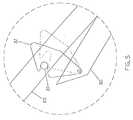
- FIG. 5is a close-up view of a transport latch.
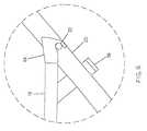
- FIG. 6is a close up view of a set-up latch.
- an apparatus 10is employed for carrying and supporting a portable table saw 12 .
- the saw 12can be one of a number of commercially available makes and models of portable table saws, such as but not limited to those manufactured by such companies known as DEWALT, BLACK & DECKER, HITACHI, DELTA, MAKITA, RYOBI, SKIL, and CRAFTSMAN.
- the saw 12generally has a body 14 including provision for attachment to a bench, table or frame at bottom of body 14 thereof.
- the body 14is fastened by means of a threaded screw attachment to the bench, table or frame.
- This threaded screw method of fasteningis well known in the existing art of fastening and therefore is not specified in detail. However, other methods, as known in the art of fastening may be employed without departing from the principles of the invention.
- the apparatus 10includes a main support frame 20 which is pivotally connected to a secondary support frame 30 via two pivotal connections 16 .
- These pivotal connections 16may be one of several methods as is well known in the art of pivotal connections and therefore are not specified in detail.
- the main support frame 20includes a pair of identical pins 22 for supporting a platform 18 when apparatus 10 is in the set-up position, as can be seen best in FIGS. 1 & 2.
- this preferred embodimentis described comprising a platform 18 , it should be understood that any type of lateral support structure, such as platform 18 , crossbar(s), brace, frame, etc., could be utilized to support saw 12 and therefore fall within the scope of this invention.
- the main support frame 20also includes an out-feed work support 26 which is to support an object after it is fed through the saw blade 28 at which point the object extends past the edge of saw 12 .
- the out-feed work support 26is positioned to be in the same plane as the top of the saw 12 when apparatus 10 is in the set-up position. This can be seen more clearly in FIG. 2 .
- the out-feed work support 26is also used as a handle while apparatus 10 is being transported as can be seen in FIGS. 3 & 4.
- shimsmay be placed below saw 12 to raise or lower it as necessary.
- a mechanical systeme.g., a jack or a lift
- the out-feed work support 26could be extendable (e.g., telescoping) to adjust its height.
- the secondary support frame 30includes a pair of identical latching mechanisms, transport latches 32 on each side of the secondary support frame 30 , as can be seen in FIG. 1 .
- the transport latches 32are each shaped and placed precisely so as to engage with pins 22 when the apparatus 10 is in the collapsed position as can be seen in FIGS. 3 & 4.
- the transport latches 24include spring tension and are designed such that during the process of collapsing the apparatus 10 , the latches will be guided by pins 22 to swing over the pins and the spring tension will then snap the latches onto the pins.
- FIG. 5is an expanded view of transport latch 32 and pin 22 when apparatus 10 is collapsed as shown by the dashed circle 5 in FIG. 4 .
- the secondary support frame 30also includes a cross rail 34 as can be seen in FIG. 1 .
- pivotal connections 17are provided to connect the platform 18 to the secondary support frame 30 as may be seen in FIG. 1 .
- These pivotal connections 17may be one of several methods as is well known in the art of pivotal connections and therefore are not specified in detail.
- the platform 18includes a pair of identical latch devices, set-up latches 24 .
- Set-up latch 24is best shown in FIG. 2 .
- Another set-up latchis identical to and placed directly opposite set-up latch 24 on platform 18 .
- Set-up latches 24are both precisely shaped and placed so as to engage with pins 22 when apparatus 10 is in the set-up position as can be seen in FIGS. 1 & 2.
- FIG. 6is an expanded view of a set-up latch 24 and pin 22 when apparatus 10 is in the set-up position as shown by the dashed circle 6 in FIG. 2 .
- the platform 18also includes a pair of devices, retainers 36 , that are slidably engaged to main frame support 20 .
- Each retainer 36is shaped and sized so as to keep platform 18 loosely connected to apparatus 10 when apparatus 10 is in the collapsed position as well as provide adequate clearance to engage the set-up latches 24 to pins 22 during the set-up process.
- the platform 18contains a surface for which to affix the saw 12 .
- This surfacemay be formed of some rigid durable material of relatively low mass, such as but not limited to plywood, particle board, or plastic. Other rigid materials fulfilling the specified requirements will serve the purpose of the surface as well.
- the platform 18includes a setup handle 38 .
- the setup handle 38may be constructed of one of many means so as to provide the necessary function. Preferably, it is connected to platform 18 by means of a flexible tether, such as but not limited to, rope, string, cable or wire. Other means of attachment as is well known in the art of attachment may also be used.
- the apparatus 10also includes a pair of wheels 42 mounted proximate the pivot connection of platform 18 and secondary support 30 .
- out-feed work support 26as a handle while in transit when apparatus 10 is in transport mode as can be seen in FIGS. 3 and 4 (i.e., the “collapsed position”).
- the operatorwishes apparatus 10 to be set-up, he/she continues to hold out-feed work support 26 with one hand and grasps setup handle 38 with the other.
- the operatorplaces one foot on cross rail 34 and proceeds to pull setup handle 38 while simultaneously pushing cross rail 34 downward with foot. This process is continued until both set-up latches 24 are lifted up and over each of pins 22 until set-up latches 24 are able to clear over pins 22 .
- the operatorthen eases tension on setup handle 38 and cross rail 34 in such manner so as to engage set-up latches 24 with pins 22 .
- the set-up operationis now complete and apparatus 10 is ready for use (i.e., it is in the “set-up position”).
- the handle on main frame support 26resides at the same height as the saw top to provide the out-feed support for the saw 12 .
- apparatus 10To collapse apparatus 10 , the operator simply reverses the set-up procedure. Apparatus 10 will then be supported by wheels 42 and will be ready for transport and/or stowage.
- an apparatusfor the purpose of supporting and carrying a portable table saw.
- the inventionis easy to use. It is quick to set up and collapse for storage and possesses ease of mobility utilizing a set of wheels. It provides a stable means of support which helps to provide a safe work environment for the operator.
- the out-feed work support 26may be adjustable in height so as to accommodate many different makes and models of saw 12 . This would provide for economical manufacture.
- the platform 18may include “shim blocks” to raise the height of saw 12 .
- Other means and methodsmay be employed to substitute the function of retainers 36 , as long as the method does not depart from the principles of the invention.
- Various connection and latching meansmay be employed throughout that serve the necessary function without departing from the principles of the invention.
- collapsible tableis described with reference to a table saw, it should be understood that the table could be used along with any type of tool (e.g., a cutting, sanding, grinding, mitering or milling device) in which an out feed support is useful.
- a toole.g., a cutting, sanding, grinding, mitering or milling device
Landscapes
- Engineering & Computer Science (AREA)
- Mechanical Engineering (AREA)
- Life Sciences & Earth Sciences (AREA)
- Wood Science & Technology (AREA)
- Forests & Forestry (AREA)
- Workshop Equipment, Work Benches, Supports,Or Storage Means (AREA)
Abstract
Description
This application claims the benefit of provisional patent application serial No. 60/175,180 filed on Jan. 10, 2000, entitled “Collapsable Portable Saw Stand.”
1. Field of Invention
This invention relates to a method and apparatus for supporting and carrying a portable table saw, particularly an apparatus that supports a table saw as well as the workpiece on the out-feed end of the table saw.
2. Description of Prior Art
It is desirable for anyone using a portable table saw to provide a safe and stable means of support from which to work, as well as the ease of mobility and convenience of portability. It is also desirable to quickly and easily set up and take down any apparatus employed to support the saw. This makes for convenience and efficiency for tradespeople as well as anyone else using the saw. Typically, users would carry the saw to the work place and then set up “on-the-fly” utilizing what ever temporary means that can be mustered up quickly. Not only is this practice inconvenient, it is unsafe.
Several manufacturers have designed and marketed apparatuses for supporting and/or transporting the saw. The problems with most of these designs are that they are not very portable. Nor do they provide the stability required of a table saw. Also, none of them provide a means for out-feed work support. The out-feed is that portion of the workpiece that has been run through the table saw as it comes off the rear of the table. Long pieces of wood being cut on a table saw can become cumbersome and unsafe as it is pushed through the blade as the weight on the out-feed section is usually unsupported. This unsupported weight tends to create a condition of unbalance and may cause the entire apparatus to tip.
TROJAN Manufacturing of Portland, Oreg. offers two such saw stands. U.S. Pat. No. 5,778,953 to Lawrence D. Braddock (Jul. 14, 1999) refers to TROJAN's RIPMASTER Table Saw Stand. This stand does have wheels for transports but it is not easily set up and taken down for transport. With the RIPMASTER, the operator must initiate several steps to put it together and take it apart each time it is to be used or put away. Once the RIPMASTER is set up, it lacks the stability required to push a large workpiece through, making it susceptible to tipping over. It also lacks the all important out-feed work support. Without a out-feed support, the long workpiece becomes heavy on the out-feed end and tends to make the apparatus unbalanced.
TROJAN Manufacturing also offers another saw stand specifically for DEWALT's model DW-744 table saw. MS-2000X as seen in TOOL CRIB OF THE NORTH Catalog 904 (Jun. 1, 1999) refers to this new stand. It too, as does the RIPMASTER lacks the out-feed support. It does have wheels for transport, but the handle used for transport is low and some users may have to stoop uncomfortably to reach it, possibly causing undue back strain. Also, the legs must be taken off to take it down and put back on for set up. This makes it inconvenient for portability as it must be assembled each time it is set up and unassembled to take it down.
U.S. Pat. No. 4,955,941 to Tony Rousseau (Jul. 11, 1990) refers to a stand for portable table saws marketed by ROUSSEAU Company. This stand too, is cumbersome to set up and transport. It also lacks wheels for easy transportability. An optional out-feed support is available as an add-on device, but this add-on apparatus is cumbersome to attach each time of use and detracts from portability. It also adds expense to purchase the entire apparatus.
Both of TROJAN Manufacturing's table saw stands as well as ROUSSEAU's lacks the stability required for pushing a larger workpiece through the saw. Each of these designs require the workpiece to be pushed across the direction of the legs of the stand, or sideways. This is not as stable as a design such as the current invention in which the user pushes the workpiece directly against the support structures, or legs.
In a first aspect, the invention provides a collapsible stand for supporting a machining tool, comprising: a lateral support structure for holding the machining tool; a secondary support frame having a first end pivotally attached to a first end the lateral support structure; and a main support frame pivotally attached to the secondary support frame, wherein the main support frame comprises a handle at a first end for transporting the stand in its collapsed position, and wherein the handle comprises an out feed support for the machining tool when the stand is in its set up position.
In a second aspect, the invention provides a collapsible stand for supporting a tool, comprising: a lateral support structure for supporting the tool; and a main frame support having a handle for transporting the stand in a collapsed position, wherein the handle provides an out feed support for the tool in a set-up position.
In a further aspect, the invention provides an apparatus for carrying and supporting a portable bench top machining tool, said bench top machining tool having a predetermined means for fastening to a planar surface thereof, the apparatus comprising:
(a) a relatively rigid main support frame, said main support frame including two substantially parallel rails;
(b) a out-feed work support consisting of a member attached substantially perpendicular to and at first ends of said parallel rails of said main support frame for either or both purposes of supporting a long workpiece as it is passed through said portable bench top machining tool and as a handle for when said apparatus is being transported or otherwise handled;
(c) a secondary support frame for supporting said apparatus during use; said secondary support frame including two substantially parallel rails and a cross rail positioned substantially perpendicular to and near first ends of said parallel rails of said secondary support frame;
(d) a set of pivotal connections joining each said parallel rail of said secondary support frame at approximate mid points of each said parallel rail of said secondary support frame with each corresponding said parallel rail of said main support frame, at a point between the mid points and the second ends of said parallel rails of said main support frame;
(e) a platform including a planar surface for the purpose of fastening the bench top machining tool; first end of said platform being pivotally connected to second end of said parallel rails of said secondary support frame; and
(f) a means for removably affixing, demountably connecting, releasably latching or otherwise temporarily securing second end of said platform to said main support frame at a point such that said platform will rest relatively parallel to ground plane when said apparatus is set-up for use whereby the user shall be provided with a conveniently collapsible, stable and safe support structure to accommodate the machining tool.
Accordingly, several advantages of the invention are:
(i) Ease of operation. The current invention is collapsible and can be set up with a minimum of time and effort. There are no removable parts that must be assembled and unassembled between usage. Simply snap it together to collapse and unsnap to set up.
(ii) Mobility. The invention is easily transportable with a pair of large wheels that easily roll over the ground and even up steps.
(iii) Out-feed support. The invention incorporates a out-feed work support structure that supports the weight of a long workpiece. This feature eliminates the need for the user to bear down on the in-feed portion of the workpiece with his hands being close to the blade, in order to prevent the workpiece from falling. It also reduces the likeliness of the saw and stand tipping over from the weight of the out-feed workpiece.
(iv) Simple design. The invention utilizes a simple design which is economical to fabricate and easily used.
(v) Simplicity and convenience of use which makes using this saw stand more efficient and thus more profitable for professional trades people.
Still further objects and advantages will become apparent from a consideration of the ensuing description and accompanying drawings.
FIG. 1 is an isometric view of my invention in the set-up position, with a table saw affixed and ready for use.
FIG. 2 is an orthogonal view of my invention in the set-up position with a table saw affixed and ready for use.
FIG. 3 is an isometric view of my invention in the collapsed position with table saw affixed and ready for transport.
FIG. 4 is an orthogonal view of my invention in the collapsed position with table saw affixed and ready for transport.
FIG. 5 is a close-up view of a transport latch.
FIG. 6 is a close up view of a set-up latch.
Referring to FIGS. 1 through 4, anapparatus 10 is employed for carrying and supporting a portable table saw12. Thesaw 12 can be one of a number of commercially available makes and models of portable table saws, such as but not limited to those manufactured by such companies known as DEWALT, BLACK & DECKER, HITACHI, DELTA, MAKITA, RYOBI, SKIL, and CRAFTSMAN. Thesaw 12 generally has abody 14 including provision for attachment to a bench, table or frame at bottom ofbody 14 thereof. Typically, thebody 14 is fastened by means of a threaded screw attachment to the bench, table or frame. This threaded screw method of fastening is well known in the existing art of fastening and therefore is not specified in detail. However, other methods, as known in the art of fastening may be employed without departing from the principles of the invention.
Theapparatus 10 includes amain support frame 20 which is pivotally connected to asecondary support frame 30 via twopivotal connections 16. Thesepivotal connections 16 may be one of several methods as is well known in the art of pivotal connections and therefore are not specified in detail.
Themain support frame 20 includes a pair ofidentical pins 22 for supporting aplatform 18 whenapparatus 10 is in the set-up position, as can be seen best in FIGS. 1 & 2. Although this preferred embodiment is described comprising aplatform 18, it should be understood that any type of lateral support structure, such asplatform 18, crossbar(s), brace, frame, etc., could be utilized to supportsaw 12 and therefore fall within the scope of this invention.
Themain support frame 20 also includes an out-feed work support 26 which is to support an object after it is fed through thesaw blade 28 at which point the object extends past the edge ofsaw 12. The out-feed work support 26 is positioned to be in the same plane as the top of thesaw 12 whenapparatus 10 is in the set-up position. This can be seen more clearly in FIG.2. The out-feed work support 26 is also used as a handle whileapparatus 10 is being transported as can be seen in FIGS. 3 & 4. To achieve the correct height of the out-feed work support 26 in relation to the top of thesaw 12, shims may be placed below saw12 to raise or lower it as necessary. Alternatively, a mechanical system (e.g., a jack or a lift) could be used to raise or lower the saw. In addition, the out-feed work support 26 could be extendable (e.g., telescoping) to adjust its height.
Thesecondary support frame 30 includes a pair of identical latching mechanisms, transport latches32 on each side of thesecondary support frame 30, as can be seen in FIG.1. The transport latches32 are each shaped and placed precisely so as to engage withpins 22 when theapparatus 10 is in the collapsed position as can be seen in FIGS. 3 & 4. Most preferably, the transport latches24 include spring tension and are designed such that during the process of collapsing theapparatus 10, the latches will be guided bypins 22 to swing over the pins and the spring tension will then snap the latches onto the pins. FIG. 5 is an expanded view oftransport latch 32 andpin 22 whenapparatus 10 is collapsed as shown by the dashedcircle 5 in FIG.4. Thesecondary support frame 30 also includes across rail 34 as can be seen in FIG.1.
Twopivotal connections 17 are provided to connect theplatform 18 to thesecondary support frame 30 as may be seen in FIG.1. Thesepivotal connections 17 may be one of several methods as is well known in the art of pivotal connections and therefore are not specified in detail.
Theplatform 18 includes a pair of identical latch devices, set-up latches24. Set-up latch 24 is best shown in FIG.2. Another set-up latch is identical to and placed directly opposite set-up latch 24 onplatform 18. Set-up latches24 are both precisely shaped and placed so as to engage withpins 22 whenapparatus 10 is in the set-up position as can be seen in FIGS. 1 & 2. FIG. 6 is an expanded view of a set-up latch 24 andpin 22 whenapparatus 10 is in the set-up position as shown by the dashed circle6 in FIG.2.
Theplatform 18 also includes a pair of devices,retainers 36, that are slidably engaged tomain frame support 20. Eachretainer 36 is shaped and sized so as to keepplatform 18 loosely connected toapparatus 10 whenapparatus 10 is in the collapsed position as well as provide adequate clearance to engage the set-up latches24 topins 22 during the set-up process.
Theplatform 18 contains a surface for which to affix thesaw 12. This surface may be formed of some rigid durable material of relatively low mass, such as but not limited to plywood, particle board, or plastic. Other rigid materials fulfilling the specified requirements will serve the purpose of the surface as well.
Theplatform 18 includes asetup handle 38. The setup handle38 may be constructed of one of many means so as to provide the necessary function. Preferably, it is connected toplatform 18 by means of a flexible tether, such as but not limited to, rope, string, cable or wire. Other means of attachment as is well known in the art of attachment may also be used.
Theapparatus 10 also includes a pair ofwheels 42 mounted proximate the pivot connection ofplatform 18 andsecondary support 30.
The use and operation of the invention is as follows:
The operator uses out-feed work support 26 as a handle while in transit whenapparatus 10 is in transport mode as can be seen in FIGS. 3 and 4 (i.e., the “collapsed position”). When the operator wishesapparatus 10 to be set-up, he/she continues to hold out-feed work support 26 with one hand and grasps setup handle38 with the other. The operator then places one foot oncross rail 34 and proceeds to pull setup handle38 while simultaneously pushingcross rail 34 downward with foot. This process is continued until both set-up latches24 are lifted up and over each ofpins 22 until set-up latches24 are able to clear over pins22. The operator then eases tension onsetup handle 38 andcross rail 34 in such manner so as to engage set-up latches24 withpins 22. The set-up operation is now complete andapparatus 10 is ready for use (i.e., it is in the “set-up position”). In the set-up position, the handle onmain frame support 26 resides at the same height as the saw top to provide the out-feed support for thesaw 12.
To collapseapparatus 10, the operator simply reverses the set-up procedure.Apparatus 10 will then be supported bywheels 42 and will be ready for transport and/or stowage.
Accordingly, it can be seen that, according to the invention, an apparatus is provided for the purpose of supporting and carrying a portable table saw. The invention is easy to use. It is quick to set up and collapse for storage and possesses ease of mobility utilizing a set of wheels. It provides a stable means of support which helps to provide a safe work environment for the operator.
Although the description above contains many specifics, these should not be construed as limiting the scope of the invention but as merely providing illustrations of some of the presently preferred embodiments of this invention. Various other embodiments and ramifications are possible within it's scope. For example, the out-feed work support 26 may be adjustable in height so as to accommodate many different makes and models ofsaw 12. This would provide for economical manufacture. Theplatform 18 may include “shim blocks” to raise the height ofsaw 12. Other means and methods may be employed to substitute the function ofretainers 36, as long as the method does not depart from the principles of the invention. Various connection and latching means may be employed throughout that serve the necessary function without departing from the principles of the invention. In addition, although the collapsible table is described with reference to a table saw, it should be understood that the table could be used along with any type of tool (e.g., a cutting, sanding, grinding, mitering or milling device) in which an out feed support is useful.
Claims (20)
1. A collapsible stand for supporting a machining tool, comprising:
a lateral support structure for holding the machining tool;
a secondary support frame having a first end pivotally attached to a first end of the lateral support structure; and
a main support frame pivotally attached to the secondary support frame, wherein the main support frame comprises a handle at a first end for transporting the stand in its collapsed position,
wherein the handle comprises an out feed support for the machining tool when the stand is in its set up position, and wherein the main support frame and the secondary support frame collapse in opposing directions.
2. The collapsible stand ofclaim 1 , wherein the lateral support structure comprises a platform.
3. The collapsible stand ofclaim 1 , wherein the secondary support frame provides support to the first end of the lateral support structure when the stand is in its set up position.
4. The collapsible stand ofclaim 1 , wherein the secondary support frame folds beneath the lateral support structure when the stand in its collapsed position.
5. The collapsible stand ofclaim 1 , wherein main support frame provides support to a second end of the lateral support structure when the stand is in its set up position.
6. The collapsible stand ofclaim 5 , wherein the second end of the lateral support structure is slidably engaged to the main support frame and includes a locking mechanism for securing the lateral support structure to the main support frame.
7. The collapsible stand ofclaim 1 , further comprising a pair of wheels attached proximate the first end of the lateral support structure.
8. The collapsible stand ofclaim 7 , wherein the stand collapses into a relatively flat configuration such that the handle and pair of wheels reside at opposed ends of the stand.
9. The collapsible stand ofclaim 8 , further comprising a releasable latch for securing said stand in the collapsed position.
10. The collapsible stand ofclaim 1 , further including a setup handle attached to a second end of the lateral support structure for facilitating collapse and setup of the stand.
11. A collapsible stand for supporting a machining tool, comprising:
a lateral support structure for holding the machining tool having a first end and a second end;
a pair of wheels attached proximate the first end;
a secondary support frame pivotally attached to the first end; and
a main support frame pivotally attached to the secondary support frame, wherein the main support frame comprises a handle at a first end for transporting the stand in its collapsed position, and wherein the handle comprises an out feed support for the machining tool in a set-up position.
12. The stand ofclaim 11 , wherein the main support frame detachably supports the second end in the set up position.
13. The stand ofclaim 11 , further comprising a releasable latch for securing said stand in the collapsed position.
14. The stand ofclaim 11 , wherein the handle is extendable.
15. A collapsible stand for supporting a tool, comprising:
a lateral support structure for supporting the tool; and
a main support frame having a handle for transporting the stand in a collapsed position, wherein the handle provides an out feed support for the tool in a set-up position, and wherein the main support frame is substantially planar in the set-up position.
16. The collapsible stand ofclaim 15 , wherein the main support frame includes a releasable locking mechanism for securing the lateral support structure to the main frame support in the setup position.
17. The collapsible stand ofclaim 15 , wherein the main support frame folds relatively parallel to the lateral support structure in the collapsed position.
18. The collapsible stand ofclaim 15 , further comprising a secondary support frame with a first location pivotally attached to the lateral support structure and a second location pivotally attached to the main frame support.
19. The collapsible stand ofclaim 18 , further comprising a wheel mounted proximate the first location of the secondary support frame.
20. The collapsible stand ofclaim 15 , wherein the handle is extendable.
Priority Applications (2)
| Application Number | Priority Date | Filing Date | Title |
|---|---|---|---|
| US09/749,334US6578856B2 (en) | 2000-01-10 | 2000-12-27 | Collapsible portable saw stand |
| PCT/US2001/048026WO2002051600A1 (en) | 2000-12-27 | 2001-12-11 | Collapsible portable saw stand |
Applications Claiming Priority (2)
| Application Number | Priority Date | Filing Date | Title |
|---|---|---|---|
| US17518000P | 2000-01-10 | 2000-01-10 | |
| US09/749,334US6578856B2 (en) | 2000-01-10 | 2000-12-27 | Collapsible portable saw stand |
Publications (2)
| Publication Number | Publication Date |
|---|---|
| US20010047712A1 US20010047712A1 (en) | 2001-12-06 |
| US6578856B2true US6578856B2 (en) | 2003-06-17 |
Family
ID=25013295
Family Applications (1)
| Application Number | Title | Priority Date | Filing Date |
|---|---|---|---|
| US09/749,334Expired - Fee RelatedUS6578856B2 (en) | 2000-01-10 | 2000-12-27 | Collapsible portable saw stand |
Country Status (2)
| Country | Link |
|---|---|
| US (1) | US6578856B2 (en) |
| WO (1) | WO2002051600A1 (en) |
Cited By (99)
| Publication number | Priority date | Publication date | Assignee | Title |
|---|---|---|---|---|
| US20030209884A1 (en)* | 2002-05-13 | 2003-11-13 | Baxter International Inc. | Adaptable blood processing platforms |
| US6813983B2 (en) | 2000-09-29 | 2004-11-09 | Sd3, Llc | Power saw with improved safety system |
| US6826988B2 (en) | 2000-09-29 | 2004-12-07 | Sd3, Llc | Miter saw with improved safety system |
| US6857345B2 (en) | 2000-08-14 | 2005-02-22 | Sd3, Llc | Brake positioning system |
| US20050045781A1 (en)* | 2003-08-25 | 2005-03-03 | Kenneth Brazell | Collapsible stand for a bench-top power tool |
| US6877410B2 (en) | 2000-09-29 | 2005-04-12 | Sd3, Llc | Miter saw with improved safety system |
| US6880440B2 (en) | 2000-09-29 | 2005-04-19 | Sd3, Llc | Miter saw with improved safety system |
| US6886836B1 (en)* | 2002-12-05 | 2005-05-03 | Robert W. Wise | Counterbalanced universal mobile saw stand |
| US20050093258A1 (en)* | 2003-10-31 | 2005-05-05 | Brazell Kenneth M. | Collapsible stand for a bench-top power tool |
| US6920814B2 (en) | 2000-08-14 | 2005-07-26 | Sd3, Llc | Cutting tool safety system |
| US20050199768A1 (en)* | 2004-03-12 | 2005-09-15 | Credo Technology Corporation | Collapsible rolling support stand |
| US6945149B2 (en) | 2001-07-25 | 2005-09-20 | Sd3, Llc | Actuators for use in fast-acting safety systems |
| US6945148B2 (en) | 2000-09-29 | 2005-09-20 | Sd3, Llc | Miter saw with improved safety system |
| US20050212236A1 (en)* | 2004-03-12 | 2005-09-29 | 500 Group, Inc. | Collapsible multifunction apparatus |
| US6957601B2 (en) | 2000-08-14 | 2005-10-25 | Sd3, Llc | Translation stop for use in power equipment |
| US20060005682A1 (en)* | 2004-07-07 | 2006-01-12 | Gehret Robert S | Support assembly for benchtop tools |
| US6994004B2 (en) | 2000-09-29 | 2006-02-07 | Sd3, Llc | Table saw with improved safety system |
| US6997090B2 (en) | 2001-08-13 | 2006-02-14 | Sd3, Llc | Safety systems for power equipment |
| US7000514B2 (en) | 2001-07-27 | 2006-02-21 | Sd3, Llc | Safety systems for band saws |
| US7024975B2 (en) | 2000-08-14 | 2006-04-11 | Sd3, Llc | Brake mechanism for power equipment |
| US20060075943A1 (en)* | 2004-10-07 | 2006-04-13 | P & F Brother Industrial Corporation | Foldable frame assembly for suspending a machine above a ground surface |
| US7055417B1 (en) | 1999-10-01 | 2006-06-06 | Sd3, Llc | Safety system for power equipment |
| US20060118012A1 (en)* | 2004-11-10 | 2006-06-08 | Zag Industries Ltd. | Collapsible clamping work table |
| US20060145045A1 (en)* | 2005-01-03 | 2006-07-06 | John Chisholm | Portable collapsible stand |
| US7077039B2 (en) | 2001-11-13 | 2006-07-18 | Sd3, Llc | Detection system for power equipment |
| US7080814B1 (en)* | 2004-10-29 | 2006-07-25 | Brooks Phillip A | Assembly configurable as display stand or a wheeled carrier |
| US7100483B2 (en) | 2000-08-14 | 2006-09-05 | Sd3, Llc | Firing subsystem for use in a fast-acting safety system |
| USD529252S1 (en)* | 2005-01-03 | 2006-09-26 | Uper Made Products Co., Ltd. | Table saw cart |
| US7137326B2 (en) | 2000-08-14 | 2006-11-21 | Sd3, Llc | Translation stop for use in power equipment |
| US20070012826A1 (en)* | 2005-06-29 | 2007-01-18 | Durq Machinery Corp. | Mobile power tool stand |
| US7171879B2 (en) | 2001-07-02 | 2007-02-06 | Sd3, Llc | Discrete proximity detection system |
| US7197969B2 (en) | 2001-09-24 | 2007-04-03 | Sd3, Llc | Logic control with test mode for fast-acting safety system |
| US7210383B2 (en) | 2000-08-14 | 2007-05-01 | Sd3, Llc | Detection system for power equipment |
| US20070102892A1 (en)* | 2005-11-09 | 2007-05-10 | Cheng-Hung Chiu | Collapsible stand for machine |
| US7225712B2 (en) | 2000-08-14 | 2007-06-05 | Sd3, Llc | Motion detecting system for use in a safety system for power equipment |
| US7231856B2 (en) | 2001-06-13 | 2007-06-19 | Sd3, Llc | Apparatus and method for detecting dangerous conditions in power equipment |
| US7284467B2 (en) | 2000-08-14 | 2007-10-23 | Sd3, Llc | Apparatus and method for detecting dangerous conditions in power equipment |
| US20070245869A1 (en)* | 2006-04-21 | 2007-10-25 | Welsh Robert P | Table saw |
| US7290472B2 (en) | 2002-01-14 | 2007-11-06 | Sd3, Llc | Miter saw with improved safety system |
| US20070278058A1 (en)* | 2006-05-31 | 2007-12-06 | Marilyn Angel | Luggage with foldable legs |
| US7308843B2 (en) | 2000-08-14 | 2007-12-18 | Sd3, Llc | Spring-biased brake mechanism for power equipment |
| US20080067300A1 (en)* | 2006-09-18 | 2008-03-20 | Durq Machinery Corp. | Folding support for table machine |
| US7347851B1 (en) | 2004-03-09 | 2008-03-25 | Leo B Kriksunov | Needleless hypodermic jet injector apparatus and method |
| US7350445B2 (en) | 2003-08-20 | 2008-04-01 | Sd3, Llc | Brake cartridge for power equipment |
| US7350444B2 (en) | 2000-08-14 | 2008-04-01 | Sd3, Llc | Table saw with improved safety system |
| US7353737B2 (en) | 2001-08-13 | 2008-04-08 | Sd3, Llc | Miter saw with improved safety system |
| US7359174B2 (en) | 2000-08-14 | 2008-04-15 | Sd3, Llc | Motion detecting system for use in a safety system for power equipment |
| US7357056B2 (en) | 2000-09-29 | 2008-04-15 | Sd3, Llc | Cutting tool safety system |
| US7377199B2 (en) | 2000-09-29 | 2008-05-27 | Sd3, Llc | Contact detection system for power equipment |
| US7377525B1 (en)* | 2003-10-24 | 2008-05-27 | Andrew Whitmore | Portable worktable |
| US20080203259A1 (en)* | 2007-02-27 | 2008-08-28 | Ryan Harrison | Bracket |
| US20080282941A1 (en)* | 2007-03-13 | 2008-11-20 | Wise Robert W | Collapsible infeed/outfeed table |
| US7472634B2 (en) | 2003-08-20 | 2009-01-06 | Sd3, Llc | Woodworking machines with overmolded arbors |
| US7481140B2 (en) | 2005-04-15 | 2009-01-27 | Sd3, Llc | Detection systems for power equipment |
| USD587940S1 (en) | 2007-10-15 | 2009-03-10 | Keith Patrick Crowley | Stand support member |
| US7509899B2 (en) | 2000-08-14 | 2009-03-31 | Sd3, Llc | Retraction system for use in power equipment |
| US7536238B2 (en) | 2003-12-31 | 2009-05-19 | Sd3, Llc | Detection systems for power equipment |
| US20090133780A1 (en)* | 2007-11-23 | 2009-05-28 | Wy Peron Lee | Portable supporting frame for cutting machine |
| US20090188119A1 (en)* | 2007-02-13 | 2009-07-30 | Credo Technology Corporation | Linkage drive mechanism for a reciprocating tool |
| US7600455B2 (en) | 2000-08-14 | 2009-10-13 | Sd3, Llc | Logic control for fast-acting safety system |
| US7610836B2 (en) | 2000-08-14 | 2009-11-03 | Sd3, Llc | Replaceable brake mechanism for power equipment |
| US7621205B2 (en) | 1999-10-01 | 2009-11-24 | Sd3, Llc | Band saw with safety system |
| USD608969S1 (en) | 2009-04-30 | 2010-01-26 | Wise Robert W | Self-jacking four wheel cart |
| US20100095823A1 (en)* | 2007-03-16 | 2010-04-22 | Hitachi Koki, Co., Ltd. | Bench cutter |
| US20100096530A1 (en)* | 2008-10-22 | 2010-04-22 | Rexon Industrial Corp., Ltd. | Folding tool stand |
| US7707920B2 (en) | 2003-12-31 | 2010-05-04 | Sd3, Llc | Table saws with safety systems |
| US7712403B2 (en) | 2001-07-03 | 2010-05-11 | Sd3, Llc | Actuators for use in fast-acting safety systems |
| US20100171290A1 (en)* | 2000-03-02 | 2010-07-08 | Wise Robert W | Universal mobile saw stand |
| US20100213148A1 (en)* | 2009-02-20 | 2010-08-26 | Rexon Industrial Corp., Ltd. | Mobile tool stand |
| US7784507B2 (en) | 2000-09-29 | 2010-08-31 | Sd3, Llc | Router with improved safety system |
| US20100263509A1 (en)* | 2000-08-14 | 2010-10-21 | Gass Stephen F | Miter saw with safety system |
| US20100276910A1 (en)* | 2009-04-30 | 2010-11-04 | Wise Robert W | Multiple link, self-jacking work cart wa002 |
| US7827890B2 (en) | 2004-01-29 | 2010-11-09 | Sd3, Llc | Table saws with safety systems and systems to mount and index attachments |
| US7836804B2 (en) | 2003-08-20 | 2010-11-23 | Sd3, Llc | Woodworking machines with overmolded arbors |
| US20110043085A1 (en)* | 2009-08-21 | 2011-02-24 | SherpaMax LLC | Portable container and workstation |
| US8065943B2 (en) | 2000-09-18 | 2011-11-29 | Sd3, Llc | Translation stop for use in power equipment |
| US20120085074A1 (en)* | 2010-10-12 | 2012-04-12 | Tony Lin | Foldable dust collector |
| US20130055870A1 (en)* | 2002-11-01 | 2013-03-07 | Black & Decker Inc. | Tile Saw |
| US8459157B2 (en) | 2003-12-31 | 2013-06-11 | Sd3, Llc | Brake cartridges and mounting systems for brake cartridges |
| US8523123B2 (en) | 2009-03-11 | 2013-09-03 | Rexon Industrial Corp., Ltd. | Foldable tool stand |
| US8910970B2 (en) | 2011-06-10 | 2014-12-16 | Rexon Industrial Corp., Ltd. | Rapidly collapsible stand |
| US9149926B2 (en) | 2011-06-17 | 2015-10-06 | Rexon Industrial Corp., Ltd. | Collapsible stand |
| US9186736B1 (en)* | 2014-05-18 | 2015-11-17 | Chin-Chin Chang | Collapsible stand for table saw |
| US9278446B2 (en) | 2013-02-15 | 2016-03-08 | The Stanley Works Israel, Ltd. | Work bench including a vise |
| US9371954B2 (en) | 2013-02-15 | 2016-06-21 | The Stanley Works Israel Ltd. | Work bench frame |
| US9376130B1 (en)* | 2007-01-12 | 2016-06-28 | Robert W. Wise | Self-jacking mobile saw stand WA9940 |
| US9724840B2 (en) | 1999-10-01 | 2017-08-08 | Sd3, Llc | Safety systems for power equipment |
| US20180098625A1 (en)* | 2016-10-07 | 2018-04-12 | Hsun Chung Li | Convertible vehicle having a transportation mode and a fixation mode |
| US10106182B2 (en) | 2015-12-10 | 2018-10-23 | C5 Enterprises | Foldable cart system and method |
| US10160467B2 (en)* | 2017-01-11 | 2018-12-25 | Greg Josephsen | Convertible cart device |
| US10435240B1 (en)* | 2017-06-02 | 2019-10-08 | Curtis A. Stroop | Yard waste bag holding device |
| US10792834B2 (en) | 2017-06-05 | 2020-10-06 | Milwaukee Electric Tool Corporation | Table saw |
| US10813446B2 (en) | 2019-03-21 | 2020-10-27 | Robert Wise | Collapsible infeed/outfeed table with shelf |
| US11027411B2 (en) | 2018-10-24 | 2021-06-08 | Tti (Macao Commercial Offshore) Limited | Saw stand |
| US11027413B2 (en) | 2019-03-21 | 2021-06-08 | Robert Wise | Collapsible infeed/outfeed apparatus with shelf |
| US11370142B2 (en) | 2020-07-15 | 2022-06-28 | Dennis Westbrook | Wheeled saw support apparatus |
| US11890744B2 (en) | 2020-07-31 | 2024-02-06 | Techtronic Cordless Gp | Workbench-hand truck assembly |
| US12030171B2 (en) | 2020-08-31 | 2024-07-09 | Sawstop Holding Llc | Folding stand with securing mechanism |
| US12226889B2 (en) | 2020-08-31 | 2025-02-18 | Sawstop Holding Llc | Folding stand with securing mechanism |
Families Citing this family (7)
| Publication number | Priority date | Publication date | Assignee | Title |
|---|---|---|---|---|
| US6568308B2 (en)* | 2000-03-07 | 2003-05-27 | Wesley Ricker | Work table with a portable table saw support |
| JP4954680B2 (en)* | 2006-11-21 | 2012-06-20 | 株式会社マキタ | Electric tool work bench |
| EP2153945A1 (en)* | 2008-08-11 | 2010-02-17 | Robert W. Wise | Self-Jacking mobile saw stand |
| TWI393617B (en)* | 2010-12-28 | 2013-04-21 | Rexon Ind Corp Ltd | A folding stand |
| CN102313118B (en)* | 2011-09-06 | 2013-06-05 | 江苏金飞达电动工具有限公司 | Foldable hand-push type support |
| CN109178061A (en)* | 2018-07-24 | 2019-01-11 | 芜湖易测自动化设备有限公司 | A kind of spare parts processing machinery transport device |
| AT525051B1 (en)* | 2022-01-07 | 2022-12-15 | Leitner Helmut | Device for transporting an object |
Citations (40)
| Publication number | Priority date | Publication date | Assignee | Title |
|---|---|---|---|---|
| US1005063A (en)* | 1911-01-05 | 1911-10-03 | Charles A Nordstrom | Automatic truck. |
| US3082016A (en)* | 1960-09-28 | 1963-03-19 | William D Pratt | Auto cart |
| US3493262A (en)* | 1968-03-13 | 1970-02-03 | Weil Burt | Cart having collapsible legs |
| US3655212A (en)* | 1970-04-13 | 1972-04-11 | Morton Krass | Self-supporting cart |
| US3669031A (en)* | 1970-08-12 | 1972-06-13 | Willie E Cole | Portable collapsible work table |
| US3752527A (en)* | 1971-11-18 | 1973-08-14 | Weil Burt | Multi-lever one man cart adapted to be moved up and down stairs |
| US4269096A (en)* | 1979-08-20 | 1981-05-26 | Boone Harold B | Portable workstand |
| US4565382A (en)* | 1984-03-23 | 1986-01-21 | Sherman William S | Combined portable table and hand truck |
| US4611823A (en)* | 1985-02-11 | 1986-09-16 | Roco Tool Group, Inc. | Collapsible carrier stand for heavy machine |
| US4640326A (en) | 1985-01-24 | 1987-02-03 | Hewitt Timothy W | Stand for a table saw |
| US4682750A (en)* | 1986-09-26 | 1987-07-28 | Eidos Corporation | Low profile extensible support platform |
| US4714028A (en)* | 1985-04-03 | 1987-12-22 | Inaba Seisakusho Ltd. | Height adjustable table |
| US4860807A (en) | 1988-10-13 | 1989-08-29 | Ted Vacchiano | Portable workbench and power saw stand |
| US4934718A (en)* | 1987-07-29 | 1990-06-19 | Wolfgang Voegele | Multi-purpose hand truck |
| US4955941A (en) | 1989-01-23 | 1990-09-11 | Tony Rousseau | Support table for bench saw |
| US4967672A (en)* | 1989-05-24 | 1990-11-06 | Teledyne Industries, Inc. | Foldable stand |
| US4969496A (en)* | 1988-10-21 | 1990-11-13 | Romans Dennis R | Combination electric table saw and folding, mobile work bench |
| US5067535A (en)* | 1989-04-04 | 1991-11-26 | Werkzeug-Gesellschaft Mit Beschranter Haftung | Worktable |
| US5080387A (en)* | 1990-10-01 | 1992-01-14 | Ryals Dudley R | Collapsible utility carrier |
| US5224531A (en)* | 1991-10-10 | 1993-07-06 | Erich Blohm | Portable shop/toolbox |
| US5277439A (en)* | 1992-02-27 | 1994-01-11 | Pipes George R | Hand truck |
| US5452908A (en) | 1994-04-25 | 1995-09-26 | Bencic; Mirko | Collapsible work stowage cart |
| US5462102A (en)* | 1994-08-03 | 1995-10-31 | Searfoss; William A. | Adjustable rolling saw stand |
| US5479840A (en)* | 1994-06-06 | 1996-01-02 | Emerson Electric Co. | Braking system for portable machine tool |
| US5526855A (en)* | 1995-08-08 | 1996-06-18 | Graham; Donald M. | Log splitter and detachable table |
| US5529322A (en)* | 1994-10-21 | 1996-06-25 | Barton; Deborah E. | Combination transport device and portable work surface |
| US5603491A (en)* | 1995-06-16 | 1997-02-18 | Murrell; Anthony S. | Portable workstand module |
| US5642898A (en)* | 1995-07-11 | 1997-07-01 | Wise; Robert W. | Tool cart |
| US5687978A (en)* | 1995-09-21 | 1997-11-18 | Rhodes; Ivan W. | Foldable load conveyance apparatus |
| US5778953A (en)* | 1996-07-22 | 1998-07-14 | Trojan Manufacturing, Inc. | Method and apparatus for carrying and supporting a portable bench top saw |
| US5819671A (en)* | 1996-09-04 | 1998-10-13 | Ocampo; Honesto C. | Portable modular power system |
| US5863052A (en)* | 1994-10-27 | 1999-01-26 | Roman; Gregory S. | Collapsible carpentry work station and push cart combination |
| US5927745A (en)* | 1997-03-14 | 1999-07-27 | Cunningham; John | Foldable utility cart |
| US6152462A (en)* | 1999-08-17 | 2000-11-28 | Barrett; Paul D. | Convertible hand cart system |
| US6240987B1 (en)* | 2000-03-23 | 2001-06-05 | Clinton D. Birkeland | Tool supporting device |
| US6349962B1 (en)* | 2000-05-11 | 2002-02-26 | Gaviota Cart Llc | Collapsible domestic cart |
| US6371495B2 (en)* | 2000-01-24 | 2002-04-16 | Intellotech N.V. | Trolley with fold-out legs |
| US6386557B1 (en)* | 2000-11-28 | 2002-05-14 | Waterbuggy, Llc | Portable cooler caddy and cup holder |
| US6471236B2 (en)* | 1999-02-01 | 2002-10-29 | Eugene C. Eskridge | Multimode collapsible cart |
| US6471220B1 (en)* | 2000-06-13 | 2002-10-29 | Emerson Electric Co. | Cart and stand for supporting and transporting metal working apparatus |
- 2000
- 2000-12-27USUS09/749,334patent/US6578856B2/ennot_activeExpired - Fee Related
- 2001
- 2001-12-11WOPCT/US2001/048026patent/WO2002051600A1/ennot_activeApplication Discontinuation
Patent Citations (40)
| Publication number | Priority date | Publication date | Assignee | Title |
|---|---|---|---|---|
| US1005063A (en)* | 1911-01-05 | 1911-10-03 | Charles A Nordstrom | Automatic truck. |
| US3082016A (en)* | 1960-09-28 | 1963-03-19 | William D Pratt | Auto cart |
| US3493262A (en)* | 1968-03-13 | 1970-02-03 | Weil Burt | Cart having collapsible legs |
| US3655212A (en)* | 1970-04-13 | 1972-04-11 | Morton Krass | Self-supporting cart |
| US3669031A (en)* | 1970-08-12 | 1972-06-13 | Willie E Cole | Portable collapsible work table |
| US3752527A (en)* | 1971-11-18 | 1973-08-14 | Weil Burt | Multi-lever one man cart adapted to be moved up and down stairs |
| US4269096A (en)* | 1979-08-20 | 1981-05-26 | Boone Harold B | Portable workstand |
| US4565382A (en)* | 1984-03-23 | 1986-01-21 | Sherman William S | Combined portable table and hand truck |
| US4640326A (en) | 1985-01-24 | 1987-02-03 | Hewitt Timothy W | Stand for a table saw |
| US4611823A (en)* | 1985-02-11 | 1986-09-16 | Roco Tool Group, Inc. | Collapsible carrier stand for heavy machine |
| US4714028A (en)* | 1985-04-03 | 1987-12-22 | Inaba Seisakusho Ltd. | Height adjustable table |
| US4682750A (en)* | 1986-09-26 | 1987-07-28 | Eidos Corporation | Low profile extensible support platform |
| US4934718A (en)* | 1987-07-29 | 1990-06-19 | Wolfgang Voegele | Multi-purpose hand truck |
| US4860807A (en) | 1988-10-13 | 1989-08-29 | Ted Vacchiano | Portable workbench and power saw stand |
| US4969496A (en)* | 1988-10-21 | 1990-11-13 | Romans Dennis R | Combination electric table saw and folding, mobile work bench |
| US4955941A (en) | 1989-01-23 | 1990-09-11 | Tony Rousseau | Support table for bench saw |
| US5067535A (en)* | 1989-04-04 | 1991-11-26 | Werkzeug-Gesellschaft Mit Beschranter Haftung | Worktable |
| US4967672A (en)* | 1989-05-24 | 1990-11-06 | Teledyne Industries, Inc. | Foldable stand |
| US5080387A (en)* | 1990-10-01 | 1992-01-14 | Ryals Dudley R | Collapsible utility carrier |
| US5224531A (en)* | 1991-10-10 | 1993-07-06 | Erich Blohm | Portable shop/toolbox |
| US5277439A (en)* | 1992-02-27 | 1994-01-11 | Pipes George R | Hand truck |
| US5452908A (en) | 1994-04-25 | 1995-09-26 | Bencic; Mirko | Collapsible work stowage cart |
| US5479840A (en)* | 1994-06-06 | 1996-01-02 | Emerson Electric Co. | Braking system for portable machine tool |
| US5462102A (en)* | 1994-08-03 | 1995-10-31 | Searfoss; William A. | Adjustable rolling saw stand |
| US5529322A (en)* | 1994-10-21 | 1996-06-25 | Barton; Deborah E. | Combination transport device and portable work surface |
| US5863052A (en)* | 1994-10-27 | 1999-01-26 | Roman; Gregory S. | Collapsible carpentry work station and push cart combination |
| US5603491A (en)* | 1995-06-16 | 1997-02-18 | Murrell; Anthony S. | Portable workstand module |
| US5642898A (en)* | 1995-07-11 | 1997-07-01 | Wise; Robert W. | Tool cart |
| US5526855A (en)* | 1995-08-08 | 1996-06-18 | Graham; Donald M. | Log splitter and detachable table |
| US5687978A (en)* | 1995-09-21 | 1997-11-18 | Rhodes; Ivan W. | Foldable load conveyance apparatus |
| US5778953A (en)* | 1996-07-22 | 1998-07-14 | Trojan Manufacturing, Inc. | Method and apparatus for carrying and supporting a portable bench top saw |
| US5819671A (en)* | 1996-09-04 | 1998-10-13 | Ocampo; Honesto C. | Portable modular power system |
| US5927745A (en)* | 1997-03-14 | 1999-07-27 | Cunningham; John | Foldable utility cart |
| US6471236B2 (en)* | 1999-02-01 | 2002-10-29 | Eugene C. Eskridge | Multimode collapsible cart |
| US6152462A (en)* | 1999-08-17 | 2000-11-28 | Barrett; Paul D. | Convertible hand cart system |
| US6371495B2 (en)* | 2000-01-24 | 2002-04-16 | Intellotech N.V. | Trolley with fold-out legs |
| US6240987B1 (en)* | 2000-03-23 | 2001-06-05 | Clinton D. Birkeland | Tool supporting device |
| US6349962B1 (en)* | 2000-05-11 | 2002-02-26 | Gaviota Cart Llc | Collapsible domestic cart |
| US6471220B1 (en)* | 2000-06-13 | 2002-10-29 | Emerson Electric Co. | Cart and stand for supporting and transporting metal working apparatus |
| US6386557B1 (en)* | 2000-11-28 | 2002-05-14 | Waterbuggy, Llc | Portable cooler caddy and cup holder |
Cited By (172)
| Publication number | Priority date | Publication date | Assignee | Title |
|---|---|---|---|---|
| US7525055B2 (en) | 1999-10-01 | 2009-04-28 | Sd3, Llc | Switch box for power tools with safety systems |
| US7055417B1 (en) | 1999-10-01 | 2006-06-06 | Sd3, Llc | Safety system for power equipment |
| US10335972B2 (en) | 1999-10-01 | 2019-07-02 | Sawstop Holding Llc | Table Saws |
| US8196499B2 (en) | 1999-10-01 | 2012-06-12 | Sd3, Llc | Power equipment with detection and reaction systems |
| US7347131B2 (en) | 1999-10-01 | 2008-03-25 | Sd3, Llc | Miter saw with improved safety system |
| US9522476B2 (en) | 1999-10-01 | 2016-12-20 | Sd3, Llc | Power equipment with detection and reaction systems |
| US8408106B2 (en) | 1999-10-01 | 2013-04-02 | Sd3, Llc | Method of operating power equipment with detection and reaction systems |
| US7621205B2 (en) | 1999-10-01 | 2009-11-24 | Sd3, Llc | Band saw with safety system |
| US9969014B2 (en) | 1999-10-01 | 2018-05-15 | Sawstop Holding Llc | Power equipment with detection and reaction systems |
| US7788999B2 (en) | 1999-10-01 | 2010-09-07 | Sd3, Llc | Brake mechanism for power equipment |
| US9724840B2 (en) | 1999-10-01 | 2017-08-08 | Sd3, Llc | Safety systems for power equipment |
| US9925683B2 (en) | 1999-10-01 | 2018-03-27 | Sawstop Holding Llc | Table saws |
| US7895927B2 (en) | 1999-10-01 | 2011-03-01 | Sd3, Llc | Power equipment with detection and reaction systems |
| US20100171290A1 (en)* | 2000-03-02 | 2010-07-08 | Wise Robert W | Universal mobile saw stand |
| US8448956B2 (en)* | 2000-03-02 | 2013-05-28 | Robert W. Wise | Universal mobile saw stand |
| US8522655B2 (en) | 2000-08-14 | 2013-09-03 | Sd3, Llc | Logic control for fast-acting safety system |
| US6857345B2 (en) | 2000-08-14 | 2005-02-22 | Sd3, Llc | Brake positioning system |
| US7308843B2 (en) | 2000-08-14 | 2007-12-18 | Sd3, Llc | Spring-biased brake mechanism for power equipment |
| US7921754B2 (en) | 2000-08-14 | 2011-04-12 | Sd3, Llc | Logic control for fast-acting safety system |
| US7350444B2 (en) | 2000-08-14 | 2008-04-01 | Sd3, Llc | Table saw with improved safety system |
| US7024975B2 (en) | 2000-08-14 | 2006-04-11 | Sd3, Llc | Brake mechanism for power equipment |
| US7681479B2 (en) | 2000-08-14 | 2010-03-23 | Sd3, Llc | Motion detecting system for use in a safety system for power equipment |
| US7610836B2 (en) | 2000-08-14 | 2009-11-03 | Sd3, Llc | Replaceable brake mechanism for power equipment |
| US7832314B2 (en) | 2000-08-14 | 2010-11-16 | Sd3, Llc | Brake positioning system |
| US6920814B2 (en) | 2000-08-14 | 2005-07-26 | Sd3, Llc | Cutting tool safety system |
| US7600455B2 (en) | 2000-08-14 | 2009-10-13 | Sd3, Llc | Logic control for fast-acting safety system |
| US7359174B2 (en) | 2000-08-14 | 2008-04-15 | Sd3, Llc | Motion detecting system for use in a safety system for power equipment |
| US7284467B2 (en) | 2000-08-14 | 2007-10-23 | Sd3, Llc | Apparatus and method for detecting dangerous conditions in power equipment |
| US20100263509A1 (en)* | 2000-08-14 | 2010-10-21 | Gass Stephen F | Miter saw with safety system |
| US6957601B2 (en) | 2000-08-14 | 2005-10-25 | Sd3, Llc | Translation stop for use in power equipment |
| US7100483B2 (en) | 2000-08-14 | 2006-09-05 | Sd3, Llc | Firing subsystem for use in a fast-acting safety system |
| US7509899B2 (en) | 2000-08-14 | 2009-03-31 | Sd3, Llc | Retraction system for use in power equipment |
| US8100039B2 (en) | 2000-08-14 | 2012-01-24 | Sd3, Llc | Miter saw with safety system |
| US7137326B2 (en) | 2000-08-14 | 2006-11-21 | Sd3, Llc | Translation stop for use in power equipment |
| US7228772B2 (en) | 2000-08-14 | 2007-06-12 | Sd3, Llc | Brake positioning system |
| US8151675B2 (en) | 2000-08-14 | 2012-04-10 | Sd3, Llc | Logic control for fast-acting safety system |
| US9038515B2 (en) | 2000-08-14 | 2015-05-26 | Sd3, Llc | Logic control for fast-acting safety system |
| US7225712B2 (en) | 2000-08-14 | 2007-06-05 | Sd3, Llc | Motion detecting system for use in a safety system for power equipment |
| US7210383B2 (en) | 2000-08-14 | 2007-05-01 | Sd3, Llc | Detection system for power equipment |
| US8191450B2 (en) | 2000-08-14 | 2012-06-05 | Sd3, Llc | Power equipment with detection and reaction systems |
| US8065943B2 (en) | 2000-09-18 | 2011-11-29 | Sd3, Llc | Translation stop for use in power equipment |
| US7784507B2 (en) | 2000-09-29 | 2010-08-31 | Sd3, Llc | Router with improved safety system |
| US8186255B2 (en) | 2000-09-29 | 2012-05-29 | Sd3, Llc | Contact detection system for power equipment |
| US6877410B2 (en) | 2000-09-29 | 2005-04-12 | Sd3, Llc | Miter saw with improved safety system |
| US6880440B2 (en) | 2000-09-29 | 2005-04-19 | Sd3, Llc | Miter saw with improved safety system |
| US7377199B2 (en) | 2000-09-29 | 2008-05-27 | Sd3, Llc | Contact detection system for power equipment |
| US7357056B2 (en) | 2000-09-29 | 2008-04-15 | Sd3, Llc | Cutting tool safety system |
| US8061245B2 (en) | 2000-09-29 | 2011-11-22 | Sd3, Llc | Safety methods for use in power equipment |
| US6945148B2 (en) | 2000-09-29 | 2005-09-20 | Sd3, Llc | Miter saw with improved safety system |
| US6994004B2 (en) | 2000-09-29 | 2006-02-07 | Sd3, Llc | Table saw with improved safety system |
| US6826988B2 (en) | 2000-09-29 | 2004-12-07 | Sd3, Llc | Miter saw with improved safety system |
| US6813983B2 (en) | 2000-09-29 | 2004-11-09 | Sd3, Llc | Power saw with improved safety system |
| US9927796B2 (en) | 2001-05-17 | 2018-03-27 | Sawstop Holding Llc | Band saw with improved safety system |
| US7231856B2 (en) | 2001-06-13 | 2007-06-19 | Sd3, Llc | Apparatus and method for detecting dangerous conditions in power equipment |
| US7591210B2 (en) | 2001-07-02 | 2009-09-22 | Sd3, Llc | Discrete proximity detection system |
| US7171879B2 (en) | 2001-07-02 | 2007-02-06 | Sd3, Llc | Discrete proximity detection system |
| US7712403B2 (en) | 2001-07-03 | 2010-05-11 | Sd3, Llc | Actuators for use in fast-acting safety systems |
| US6945149B2 (en) | 2001-07-25 | 2005-09-20 | Sd3, Llc | Actuators for use in fast-acting safety systems |
| US7000514B2 (en) | 2001-07-27 | 2006-02-21 | Sd3, Llc | Safety systems for band saws |
| US6997090B2 (en) | 2001-08-13 | 2006-02-14 | Sd3, Llc | Safety systems for power equipment |
| US7353737B2 (en) | 2001-08-13 | 2008-04-08 | Sd3, Llc | Miter saw with improved safety system |
| US7197969B2 (en) | 2001-09-24 | 2007-04-03 | Sd3, Llc | Logic control with test mode for fast-acting safety system |
| US7421315B2 (en) | 2001-11-13 | 2008-09-02 | Sd3, Llc | Detection system for power equipment |
| US7077039B2 (en) | 2001-11-13 | 2006-07-18 | Sd3, Llc | Detection system for power equipment |
| US7290472B2 (en) | 2002-01-14 | 2007-11-06 | Sd3, Llc | Miter saw with improved safety system |
| US20030209884A1 (en)* | 2002-05-13 | 2003-11-13 | Baxter International Inc. | Adaptable blood processing platforms |
| US7032910B2 (en)* | 2002-05-13 | 2006-04-25 | Baxter International Inc. | Adaptable blood processing platforms |
| US20130055870A1 (en)* | 2002-11-01 | 2013-03-07 | Black & Decker Inc. | Tile Saw |
| US6886836B1 (en)* | 2002-12-05 | 2005-05-03 | Robert W. Wise | Counterbalanced universal mobile saw stand |
| US20060163441A1 (en)* | 2002-12-05 | 2006-07-27 | Wise Robert W | Counterbalanced universal mobile saw stand |
| AU2003266793B2 (en)* | 2002-12-05 | 2006-06-29 | Robert W. Wise | Counterbalanced universal mobile saw stand |
| US7472634B2 (en) | 2003-08-20 | 2009-01-06 | Sd3, Llc | Woodworking machines with overmolded arbors |
| US7836804B2 (en) | 2003-08-20 | 2010-11-23 | Sd3, Llc | Woodworking machines with overmolded arbors |
| US7350445B2 (en) | 2003-08-20 | 2008-04-01 | Sd3, Llc | Brake cartridge for power equipment |
| US7131364B2 (en) | 2003-08-25 | 2006-11-07 | Eastway Fair Company, Ltd. | Collapsible stand for a bench-top power tool |
| US20050045781A1 (en)* | 2003-08-25 | 2005-03-03 | Kenneth Brazell | Collapsible stand for a bench-top power tool |
| US7377525B1 (en)* | 2003-10-24 | 2008-05-27 | Andrew Whitmore | Portable worktable |
| US6942229B2 (en)* | 2003-10-31 | 2005-09-13 | One World Technologies Limited | Collapsible stand for a bench-top power tool |
| CN100398902C (en)* | 2003-10-31 | 2008-07-02 | 创科实业有限公司 | Foldable stand for table top electric tool |
| US20050093258A1 (en)* | 2003-10-31 | 2005-05-05 | Brazell Kenneth M. | Collapsible stand for a bench-top power tool |
| US8087438B2 (en) | 2003-12-31 | 2012-01-03 | Sd3, Llc | Detection systems for power equipment |
| US7991503B2 (en) | 2003-12-31 | 2011-08-02 | Sd3, Llc | Detection systems for power equipment |
| US20170312837A1 (en)* | 2003-12-31 | 2017-11-02 | Sd3, Llc | Table saws |
| US7866239B2 (en) | 2003-12-31 | 2011-01-11 | Sd3, Llc | Elevation mechanism for table saws |
| US10442108B2 (en)* | 2003-12-31 | 2019-10-15 | Sawstop Holding Llc | Table saws |
| US7536238B2 (en) | 2003-12-31 | 2009-05-19 | Sd3, Llc | Detection systems for power equipment |
| US9623498B2 (en) | 2003-12-31 | 2017-04-18 | Sd3, Llc | Table saws |
| US7707920B2 (en) | 2003-12-31 | 2010-05-04 | Sd3, Llc | Table saws with safety systems |
| US8122807B2 (en) | 2003-12-31 | 2012-02-28 | Sd3, Llc | Table saws with safety systems |
| US7827893B2 (en) | 2003-12-31 | 2010-11-09 | Sd3, Llc | Elevation mechanism for table saws |
| US8498732B2 (en) | 2003-12-31 | 2013-07-30 | Sd3, Llc | Detection systems for power equipment |
| US8489223B2 (en) | 2003-12-31 | 2013-07-16 | Sd3, Llc | Detection systems for power equipment |
| US8459157B2 (en) | 2003-12-31 | 2013-06-11 | Sd3, Llc | Brake cartridges and mounting systems for brake cartridges |
| US8505424B2 (en) | 2004-01-29 | 2013-08-13 | Sd3, Llc | Table saws with safety systems and systems to mount and index attachments |
| US10052786B2 (en) | 2004-01-29 | 2018-08-21 | Sawstop Holding Llc | Table saws with safety systems and systems to mount and index attachments |
| US10882207B2 (en) | 2004-01-29 | 2021-01-05 | Sawstop Holding Llc | Table saws with safety systems and systems to mount and index attachments |
| US7827890B2 (en) | 2004-01-29 | 2010-11-09 | Sd3, Llc | Table saws with safety systems and systems to mount and index attachments |
| US7347851B1 (en) | 2004-03-09 | 2008-03-25 | Leo B Kriksunov | Needleless hypodermic jet injector apparatus and method |
| US8602378B2 (en) | 2004-03-12 | 2013-12-10 | Robert Bosch Gmbh | Collapsible rolling support stand |
| US8096519B2 (en)* | 2004-03-12 | 2012-01-17 | Robert Bosch Gmbh | Collapsible rolling support stand |
| US20050199768A1 (en)* | 2004-03-12 | 2005-09-15 | Credo Technology Corporation | Collapsible rolling support stand |
| US20050212236A1 (en)* | 2004-03-12 | 2005-09-29 | 500 Group, Inc. | Collapsible multifunction apparatus |
| CN100457403C (en)* | 2004-03-12 | 2009-02-04 | 罗伯特·博世有限公司 | Collapsible rolling support stand |
| US7331596B2 (en)* | 2004-03-12 | 2008-02-19 | 500 Group Inc. | Collapsible multifunction apparatus |
| US20070063466A1 (en)* | 2004-03-12 | 2007-03-22 | 500 Group, Inc. | Collapsible multifunction apparatus |
| US8313076B2 (en) | 2004-03-12 | 2012-11-20 | Robert Bosch Gmbh | Collapsible rolling support stand |
| US20060005682A1 (en)* | 2004-07-07 | 2006-01-12 | Gehret Robert S | Support assembly for benchtop tools |
| AU2005202885B2 (en)* | 2004-07-07 | 2010-05-27 | Black & Decker, Inc. | Support assembly for benchtop tools |
| US20060075943A1 (en)* | 2004-10-07 | 2006-04-13 | P & F Brother Industrial Corporation | Foldable frame assembly for suspending a machine above a ground surface |
| US7222865B2 (en)* | 2004-10-07 | 2007-05-29 | P & F Brother Industrial Corporation | Foldable frame assembly for suspending a machine above a ground surface |
| US7080814B1 (en)* | 2004-10-29 | 2006-07-25 | Brooks Phillip A | Assembly configurable as display stand or a wheeled carrier |
| US20060118012A1 (en)* | 2004-11-10 | 2006-06-08 | Zag Industries Ltd. | Collapsible clamping work table |
| US7588255B2 (en) | 2004-11-10 | 2009-09-15 | Zag Industries, Ltd. | Collapsible clamping work table |
| US7255355B2 (en)* | 2005-01-03 | 2007-08-14 | Mk Diamond Products, Inc. | Portable collapsible stand |
| USD529252S1 (en)* | 2005-01-03 | 2006-09-26 | Uper Made Products Co., Ltd. | Table saw cart |
| US20060145045A1 (en)* | 2005-01-03 | 2006-07-06 | John Chisholm | Portable collapsible stand |
| US7481140B2 (en) | 2005-04-15 | 2009-01-27 | Sd3, Llc | Detection systems for power equipment |
| US7487947B2 (en)* | 2005-06-29 | 2009-02-10 | Durq Machinery Corp. | Mobile power tool stand |
| US20070012826A1 (en)* | 2005-06-29 | 2007-01-18 | Durq Machinery Corp. | Mobile power tool stand |
| US7849966B2 (en) | 2005-11-09 | 2010-12-14 | Rexon Industrial Corporation Ltd. | Collapsible stand for machine |
| US20070102892A1 (en)* | 2005-11-09 | 2007-05-10 | Cheng-Hung Chiu | Collapsible stand for machine |
| US20070245869A1 (en)* | 2006-04-21 | 2007-10-25 | Welsh Robert P | Table saw |
| US8584564B2 (en)* | 2006-04-21 | 2013-11-19 | Black & Decker Inc. | Table saw |
| US20070278058A1 (en)* | 2006-05-31 | 2007-12-06 | Marilyn Angel | Luggage with foldable legs |
| US20080067300A1 (en)* | 2006-09-18 | 2008-03-20 | Durq Machinery Corp. | Folding support for table machine |
| US7681893B2 (en)* | 2006-09-18 | 2010-03-23 | Durq Machinery Corp. | Folding support for table machine |
| US9376130B1 (en)* | 2007-01-12 | 2016-06-28 | Robert W. Wise | Self-jacking mobile saw stand WA9940 |
| US8549762B2 (en)* | 2007-02-13 | 2013-10-08 | Robert Bosch Gmbh | Linkage drive mechanism for a reciprocating tool |
| US20090188119A1 (en)* | 2007-02-13 | 2009-07-30 | Credo Technology Corporation | Linkage drive mechanism for a reciprocating tool |
| US20080203259A1 (en)* | 2007-02-27 | 2008-08-28 | Ryan Harrison | Bracket |
| US7631847B2 (en) | 2007-02-27 | 2009-12-15 | Techtronic Power Tools Technology Limited | Power tool bracket |
| US20080282941A1 (en)* | 2007-03-13 | 2008-11-20 | Wise Robert W | Collapsible infeed/outfeed table |
| US7543614B2 (en) | 2007-03-13 | 2009-06-09 | Wise Robert W | Collapsible infeed/outfeed table |
| US20100095823A1 (en)* | 2007-03-16 | 2010-04-22 | Hitachi Koki, Co., Ltd. | Bench cutter |
| USD587940S1 (en) | 2007-10-15 | 2009-03-10 | Keith Patrick Crowley | Stand support member |
| US7882870B2 (en)* | 2007-11-23 | 2011-02-08 | Wy Peron Lee | Portable supporting frame for cutting machine |
| US20090133780A1 (en)* | 2007-11-23 | 2009-05-28 | Wy Peron Lee | Portable supporting frame for cutting machine |
| US20130175791A1 (en)* | 2008-10-22 | 2013-07-11 | Rexon Industrial Corp., Ltd. | Folding tool stand |
| US20100096530A1 (en)* | 2008-10-22 | 2010-04-22 | Rexon Industrial Corp., Ltd. | Folding tool stand |
| US8579320B2 (en)* | 2008-10-22 | 2013-11-12 | Rexon Industrial Corp., Ltd. | Folding tool stand |
| US8464994B2 (en)* | 2008-10-22 | 2013-06-18 | Rexon Industrial Corp., Ltd. | Folding tool stand |
| US8517413B2 (en)* | 2009-02-20 | 2013-08-27 | Rexon Industrial Corp., Ltd. | Mobile tool stand |
| US20100213148A1 (en)* | 2009-02-20 | 2010-08-26 | Rexon Industrial Corp., Ltd. | Mobile tool stand |
| US8523123B2 (en) | 2009-03-11 | 2013-09-03 | Rexon Industrial Corp., Ltd. | Foldable tool stand |
| US20100276910A1 (en)* | 2009-04-30 | 2010-11-04 | Wise Robert W | Multiple link, self-jacking work cart wa002 |
| US7971898B2 (en) | 2009-04-30 | 2011-07-05 | Wise Robert W | Multiple link, self-jacking work cart wa002 |
| USD608969S1 (en) | 2009-04-30 | 2010-01-26 | Wise Robert W | Self-jacking four wheel cart |
| US20110043085A1 (en)* | 2009-08-21 | 2011-02-24 | SherpaMax LLC | Portable container and workstation |
| US8454717B2 (en)* | 2010-10-12 | 2013-06-04 | Tony Lin | Foldable dust collector |
| US20120085074A1 (en)* | 2010-10-12 | 2012-04-12 | Tony Lin | Foldable dust collector |
| US8910970B2 (en) | 2011-06-10 | 2014-12-16 | Rexon Industrial Corp., Ltd. | Rapidly collapsible stand |
| US9149926B2 (en) | 2011-06-17 | 2015-10-06 | Rexon Industrial Corp., Ltd. | Collapsible stand |
| US9278446B2 (en) | 2013-02-15 | 2016-03-08 | The Stanley Works Israel, Ltd. | Work bench including a vise |
| US9371954B2 (en) | 2013-02-15 | 2016-06-21 | The Stanley Works Israel Ltd. | Work bench frame |
| US9636819B2 (en) | 2013-02-15 | 2017-05-02 | The Stanley Works Israel, Ltd. | Work bench frame |
| US9186736B1 (en)* | 2014-05-18 | 2015-11-17 | Chin-Chin Chang | Collapsible stand for table saw |
| US10106182B2 (en) | 2015-12-10 | 2018-10-23 | C5 Enterprises | Foldable cart system and method |
| US10696314B1 (en) | 2015-12-10 | 2020-06-30 | Invententional Products, Llc | Foldable cart system and method |
| US20180098625A1 (en)* | 2016-10-07 | 2018-04-12 | Hsun Chung Li | Convertible vehicle having a transportation mode and a fixation mode |
| US10426265B2 (en)* | 2016-10-07 | 2019-10-01 | Hsun Chung Li | Convertible vehicle having a transportation mode and a fixation mode |
| US10160467B2 (en)* | 2017-01-11 | 2018-12-25 | Greg Josephsen | Convertible cart device |
| US10435240B1 (en)* | 2017-06-02 | 2019-10-08 | Curtis A. Stroop | Yard waste bag holding device |
| US10792834B2 (en) | 2017-06-05 | 2020-10-06 | Milwaukee Electric Tool Corporation | Table saw |
| US11407142B2 (en) | 2017-06-05 | 2022-08-09 | Milwaukee Electric Tool Corporation | Table saw |
| US11027411B2 (en) | 2018-10-24 | 2021-06-08 | Tti (Macao Commercial Offshore) Limited | Saw stand |
| US11548137B2 (en) | 2018-10-24 | 2023-01-10 | Techtronic Power Tools Technology Limited | Saw stand |
| US10813446B2 (en) | 2019-03-21 | 2020-10-27 | Robert Wise | Collapsible infeed/outfeed table with shelf |
| US11027413B2 (en) | 2019-03-21 | 2021-06-08 | Robert Wise | Collapsible infeed/outfeed apparatus with shelf |
| US11370142B2 (en) | 2020-07-15 | 2022-06-28 | Dennis Westbrook | Wheeled saw support apparatus |
| US11890744B2 (en) | 2020-07-31 | 2024-02-06 | Techtronic Cordless Gp | Workbench-hand truck assembly |
| US12030171B2 (en) | 2020-08-31 | 2024-07-09 | Sawstop Holding Llc | Folding stand with securing mechanism |
| US12226889B2 (en) | 2020-08-31 | 2025-02-18 | Sawstop Holding Llc | Folding stand with securing mechanism |
Also Published As
| Publication number | Publication date |
|---|---|
| US20010047712A1 (en) | 2001-12-06 |
| WO2002051600A1 (en) | 2002-07-04 |
Similar Documents
| Publication | Publication Date | Title |
|---|---|---|
| US6578856B2 (en) | Collapsible portable saw stand | |
| US4874025A (en) | Miter saw utility stand | |
| US5193598A (en) | Portable support stand attachable to a sawhorse | |
| US6942229B2 (en) | Collapsible stand for a bench-top power tool | |
| US7543614B2 (en) | Collapsible infeed/outfeed table | |
| US4341247A (en) | Extension table assembly for power tools | |
| US4291869A (en) | Workbench | |
| US4864941A (en) | Folding workbench with side platform | |
| US5778953A (en) | Method and apparatus for carrying and supporting a portable bench top saw | |
| US8418591B2 (en) | Power table saw with extension table | |
| US4159821A (en) | Collapsible dual-height workbench | |
| US20020179181A1 (en) | Portable, lockable, folding work bench or tool table | |
| US7882870B2 (en) | Portable supporting frame for cutting machine | |
| US8517067B2 (en) | Foldable chain saw workbench | |
| US10813446B2 (en) | Collapsible infeed/outfeed table with shelf | |
| US5119903A (en) | Collapsible sawhorse apparatus | |
| US20190039157A1 (en) | Support accessory for portable tool stands and method | |
| US6314893B1 (en) | Table frame for cutting machine | |
| US11027413B2 (en) | Collapsible infeed/outfeed apparatus with shelf | |
| US20110079127A1 (en) | Circular saw conversion table | |
| US4678170A (en) | Log holder device | |
| US20020157731A1 (en) | Portable mitre saw extension table | |
| CA2343559A1 (en) | Portable work bench - or- portable tool table | |
| US5125478A (en) | Folding sawhorse | |
| GB2276114A (en) | Workbench, especially a sawing horse |
Legal Events
| Date | Code | Title | Description |
|---|---|---|---|
| FPAY | Fee payment | Year of fee payment:4 | |
| SULP | Surcharge for late payment | ||
| REMI | Maintenance fee reminder mailed | ||
| LAPS | Lapse for failure to pay maintenance fees | ||
| STCH | Information on status: patent discontinuation | Free format text:PATENT EXPIRED DUE TO NONPAYMENT OF MAINTENANCE FEES UNDER 37 CFR 1.362 |