US6578724B1 - Connector for use in packaging aerosol containers - Google Patents
Connector for use in packaging aerosol containersDownload PDFInfo
- Publication number
- US6578724B1 US6578724B1US10/040,846US4084601AUS6578724B1US 6578724 B1US6578724 B1US 6578724B1US 4084601 AUS4084601 AUS 4084601AUS 6578724 B1US6578724 B1US 6578724B1
- Authority
- US
- United States
- Prior art keywords
- connector
- containers
- segment
- aerosol
- container
- Prior art date
- Legal status (The legal status is an assumption and is not a legal conclusion. Google has not performed a legal analysis and makes no representation as to the accuracy of the status listed.)
- Expired - Fee Related
Links
Images


Classifications
- B—PERFORMING OPERATIONS; TRANSPORTING
- B65—CONVEYING; PACKING; STORING; HANDLING THIN OR FILAMENTARY MATERIAL
- B65D—CONTAINERS FOR STORAGE OR TRANSPORT OF ARTICLES OR MATERIALS, e.g. BAGS, BARRELS, BOTTLES, BOXES, CANS, CARTONS, CRATES, DRUMS, JARS, TANKS, HOPPERS, FORWARDING CONTAINERS; ACCESSORIES, CLOSURES, OR FITTINGS THEREFOR; PACKAGING ELEMENTS; PACKAGES
- B65D67/00—Kinds or types of packaging elements not otherwise provided for
- B65D67/02—Clips or clamps for holding articles together for convenience of storage or transport
- B—PERFORMING OPERATIONS; TRANSPORTING
- B65—CONVEYING; PACKING; STORING; HANDLING THIN OR FILAMENTARY MATERIAL
- B65D—CONTAINERS FOR STORAGE OR TRANSPORT OF ARTICLES OR MATERIALS, e.g. BAGS, BARRELS, BOTTLES, BOXES, CANS, CARTONS, CRATES, DRUMS, JARS, TANKS, HOPPERS, FORWARDING CONTAINERS; ACCESSORIES, CLOSURES, OR FITTINGS THEREFOR; PACKAGING ELEMENTS; PACKAGES
- B65D71/00—Bundles of articles held together by packaging elements for convenience of storage or transport, e.g. portable segregating carrier for plural receptacles such as beer cans or pop bottles; Bales of material
- B65D71/50—Bundles of articles held together by packaging elements for convenience of storage or transport, e.g. portable segregating carrier for plural receptacles such as beer cans or pop bottles; Bales of material comprising a plurality of articles held together only partially by packaging elements formed otherwise than by folding a blank
- B65D71/502—Coaxial connections
- Y—GENERAL TAGGING OF NEW TECHNOLOGICAL DEVELOPMENTS; GENERAL TAGGING OF CROSS-SECTIONAL TECHNOLOGIES SPANNING OVER SEVERAL SECTIONS OF THE IPC; TECHNICAL SUBJECTS COVERED BY FORMER USPC CROSS-REFERENCE ART COLLECTIONS [XRACs] AND DIGESTS
- Y10—TECHNICAL SUBJECTS COVERED BY FORMER USPC
- Y10S—TECHNICAL SUBJECTS COVERED BY FORMER USPC CROSS-REFERENCE ART COLLECTIONS [XRACs] AND DIGESTS
- Y10S206/00—Special receptacle or package
- Y10S206/821—Stacking member
Definitions
- This inventionrelates to aerosol containers, and more particularly, to a connector for packaging two or more containers together so the resultant package is available for retail sale as a single unit.
- Aerosol containerscome in standard sizes and their contents are used for many purposes. Typically, aerosol containers are sold as a single unit. Sometimes, however, it is desirable to sell two containers together at a retail outlet. As a matter of convenience, rather than having the customer pick two individual containers off the shelf, it is desirable if the containers were packaged as a single unit.
- the present inventionteaches various connectors for joining at least two aerosol containers together so they can be sold as a unit.
- Two liter soda bottlesare packaged together as a two pack. Beer and soda cans and bottles are packaged together, usually as a six pack.
- the two liter packagingconsists, for example, of a plastic handle having extensions which fit over the top of each liter bottle and grasp the bottle about its neck. When carried, the bottles hang suspended from the handle.
- the six packstypically have two rows, side-by-side, of three plastic loops which fit tightly about the side of the bottle or can somewhere below the top of the bottle or can. Aerosol containers present a different packaging problem from these tops of bottles or cans. For one thing, the containers are smaller than the two liter bottles.
- aerosol containershave a removable cap which is replaced after contents of the container are dispensed. This is because all the contents of the aerosol container are usually not dispensed at one time. Accordingly, it is important that the containers be so handled that the cap is not displaced during handling. On the other hand, when a beer or soda bottle or can is opened, the contents are usually consumed in a very short period of time. Finally, regardless of whether cans or bottles are packaged together, they are arranged in a side-by-side, horizontal arrangement. With some aerosol containers, it is desirable to package them vertically.
- a connectorfor use in attaching at least two aerosol containers together so they can be sold as a unit.
- the containerscan dispense the same or different products.
- One type of connectorallows the aerosol containers to be connected together one above the other; while the other connectors allow the containers to be connected together side-by-side. Graphics can be printed on a portion of the connectors advertising the name of the product manufacturer, product information, sales price, etc.
- the connectorsare made of a plastic material which holds the containers together as a unit both for sale and storage, but which allows an individual container to be readily removed.
- the connectoris lightweight, low cost, allows easy assembly of a two container package, and is disposable.
- a connectoris used in packaging together two aerosol containers for sale as a unit.
- a first connector segmentattaches to one aerosol container, and a second connector segment attaches to the other aerosol containers.
- the connector segmentsgrasp adjacent portions of the respective aerosol containers which, in one embodiment are stacked vertically, one above the other, and in other embodiments horizontally in a side-by-side configuration.
- the connectoris formed as a one piece, integral connector.
- the connector segmentsare separate pieces with one piece attaching to the top, cap portion of the containers, and the other piece attaching to the base of the respective containers.
- the containersare handled as a single unit regardless of whether one container or the other, or the connector, is used to move the containers.
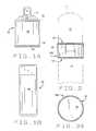
- FIG. 1Ais an elevational view of a first type aerosol container which can be packaged in a stacked, vertical configuration or in a side-by-side, horizontal configuration;
- FIG. 1Bis an elevational view of a second type aerosol container which can be packaged in a side-by-side horizontal configuration
- FIG. 2is an elevational view of a first embodiment of the invention for stacking two containers vertically;
- FIG. 3Ais a top plan view of the connector of FIG. 2
- FIG. 3Bis a bottom plan view of the connector
- FIG. 3Cis a sectional view of the connector taken along line 3 C— 3 C in FIG. 3B;
- FIG. 4is an elevational view of a second embodiment of the invention for packaging containers side-by-side;
- FIG. 5Ais a plan view of the connector of FIG. 4, and FIG. 5B is an end elevational view of the connector;
- FIGS. 5C and 5Dare respective plan and end elevational views of an alternate construction of the second embodiment of the connector
- FIG. 6is an elevational view of a third embodiment of the invention for packaging containers side-by-side;
- FIG. 7is a top plan view of the upper segment comprising the connector of FIG. 6, and FIG. 7B is a bottom plan view of the connector segment;
- FIGS. 7C and 7Dare views similar to FIGS. 7A and 7B for the lower segment of the connector of FIG. 6;
- FIG. 8is an elevational view of a vertical, stacked configuration of three containers using the connector of FIG. 2;
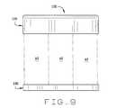
- FIG. 9is an elevational view of three packaged containers arranged side-by-side using the connectors of FIG. 6;
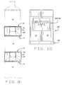
- FIG. 10is an elevational view of two packaged containers arranged side-by-side using the connectors of FIGS. 4 and 6; and,
- FIG. 11is an elevational view of two vertically stacked containers which are packaged bottom end to bottom end.
- a connector for use in packaging at least two aerosol containers together for sale of the containers as a unitis indicated generally 10 A- 10 F in the respective drawings.
- a first type of aerosol container A 1has a generally cylindrical center section M 1 , a top section T 1 attached to an upper end of the center section, and a base section or countersink B 1 attached to a lower end of the center section.
- circumferentially extending seams, S 1 and S 2 respectivelyare formed at each end of section M 1 where the other two sections are joined to the center section.
- a fluid dispensing valve Vis fitted into the top section T 1 of the container.
- a cap(not shown) may be sized to fit over the valve and seat on a shoulder formed in the top section of the container.
- FIG. 1 BAnother aerosol container construction is shown in FIG. 1 B.
- This aerosol container A 2includes a center section M 2 together with top and bottom sections (not shown).
- a fluid dispensing valve(also not shown) is again fitted to the top section of the valve.
- a removable cap Cfits over the top of the container.
- containers A 1 and A 2their sizes shown in the drawings are representative only. Further, the size and construction of the containers form no part of this invention.
- Connector 10 Ais for use in connecting together aerosol containers when the containers are stacked vertically, one above the other.
- Connector 10 Aincludes a first connector segment 12 which attaches the upper aerosol container A 1 in the stack, and a second connector segment 14 which attaches to the lower of the two aerosol containers.
- the two connector segmentsgrasp adjacent portions of the vertically stacked containers and hold them together. This allows the two containers to be handled as a single unit.
- Connector 10 Ais formed as a one piece, integral connector in which the two connector segments are joined together to form a unitary connector.
- the connectoris preferably made of a flexible, plastic material.
- connector 10 Ahas a generally circular cross-section with the inner diameter of the connector corresponding to the outer diameter of the aerosol containers.
- a common wall 16defines the base of connector segment 12 and the upper end of connector segment 14 .
- the height of segment 12is less than the height of segment 14 , and the outer end of each segment is open so to fit about a portion of the two aerosols containers packaged together.
- first connector segment 12fits about the seam S 2 formed at the lower end of the upper aerosol container in the stack.
- the second connector segment 14attaches to the seam S 1 formed at the upper end of the lower aerosol container in the stack.
- the mouth end of each connector segmentcurls inwardly as indicated at 18 and 20 respectively.
- curl 18fits over the lower end of the container about seam S 2 .
- curl 20fits over the upper end of the container about seam S 1 .
- the aerosol containers S 1include a fluid dispensing valve V fitted into its top section T 1 .
- Second container segment 14includes an annular skirt 22 which descends from the wall 16 dividing the upper and lower connector segments.
- the inner diameter of skirt 22is slightly larger than the diameter of the dispensing valve.
- Skirt 22is concentrically formed with the lower segment and depends from wall 16 a distance corresponding to the height of the dispensing valve. The skirt is lowered over the dispensing valve as connector segment 14 is fitted onto the lower container in the stack. When installed, the skirt provides stability to the resulting package.
- a second embodiment of connector 10is indicated 10 B and 10 B′.
- This embodiment of the connectoris for packaging aerosol containers A 2 in a side-by-side, horizontal relationship.
- the second embodiment of the connectoralso includes a first connector segment 12 A which attaches to a first of the aerosol containers, and a second connector segment 14 A which attaches to a second of the aerosol containers.
- the connectoris a one piece, integrally formed connector including a common wall 16 A joining the two connector segments together to form a unitary connector.
- wall 16 Ais shown to be a straight, vertical wall extending from one side of the connector to the other. The width of the wall corresponds to the diameter of the aerosol containers A 2 .
- the remainder of the segments 12 A and 14 Aare formed by sidewalls OW 1 and OW 2 which extend perpendicular to wall 16 A at each end of the wall.
- the resulting connector segmentsare generally U-shaped as shown in FIG. 5 A.
- the length of the sidewall sections forming the respective connector segmentsis each greater than a radius r of the aerosol containers A 2 . This is as shown in FIG. 5 A.
- Each end of the sidewallscurl inwardly as indicated at 24 (for connector segment 12 A) and 26 (for the other connector segment) respectively.
- the sidewalls of the connector segmentspread apart until the outer, curled end of the segment slides past the center of the container. Since the depth of the segment is greater than the radius of the container, once the outer end of the segment extends “over center”, the segment will hold the container in place.
- the sidewalls OW 1 and OW 2 of the connectorcomprise a generally flat, rectangular graphics area on which text and artwork can be printed. Or, a label (not shown) having text and artwork can be applied to this area. Since there is a similar graphics area on each side of the connector, the graphics or label can be located on both sides of the connector.
- connector 10 B′is shown to be similar to connector 10 B.
- the respective connector segments 12 A′ and 14 A′have a curved shape whose curvature generally corresponds to that of the aerosol containers A 2 .
- wall 16 A′is not a common wall extending across the width of the connector, but rather comprises a common wall extending only partially across the width of the connector.
- the sidewalls forming the connectorare again continuous, flat wall sections extending the length of the connector.
- the length of each sidewall section forming one of the connector segmentsis again greater than the radius of the container packaged by the connector; and, the ends of the sidewalls are inwardly turned as indicated at 24 ′ and 26 ′.
- these sectionsprovide a graphics area for text and artwork, or the application of labels.
- Connector 10 B′now includes arcuate sections 28 extending between the common wall section 16 A′ and the sidewalls OW 1 ′ and OW 2 ′.
- Attachment of the connector segments to the aerosol containersis as described above. That is, once the outer end of the segment extends past the centerline of a container, the segment will hold the container in place.
- a third embodiment of connector 10comprises a connector 10 C.
- Connector 10 Cis formed as single piece, molded connector having two segments 12 C and 14 C which are separated from each other when two aerosol containers are to be packaged together for sale as a single unit.
- the two connector segmentseach comprise an elongate cover piece the sides of which extend parallel to each other and the ends of which are rounded.
- the length of the connector segment 12 Ccorresponds to twice the diameter of an aerosol container at the cap C or top end of the container.
- the length of the connector segment 14 Ccorresponds to twice the diameter of the aerosol container at the base or bottom end of the container.
- the width of both connector segmentscorresponds to the diameter of the aerosol containers packaged using connector 10 C.
- the rounded ends of each connector segmenthave a radius corresponding to the radius of an aerosol container.
- Each connectorfurther has a circumferentially extending sidewall of uniform thickness.
- an interior wall 16 Cis integrally formed on the inside of segment 12 C.
- Wall 16 Cis similar to the wall 16 A′ previously described with respect to embodiment 10 B′ of the invention, and divides the segment into two separate compartments, one for each aerosol container to be packaged using connector 10 C.
- the diameter of the cavity formed by the sidewall of connector segment 12 C and wall 16 Ccorresponds to the diameter of a packaged aerosol container.
- a pair of annular skirts 22 Cis formed on the inside of the upper, end wall 23 of segment 12 C.
- Each skirt 22 Cdepends from wall 23 with the inner diameter of each skirt being slightly larger than the diameter of a dispensing valve of an aerosol container A 1 packaged using connector 10 C.
- Each skirt 22 Cis concentrically formed within a respective half of segment 12 C, the skirt depending from wall 23 a distance corresponding to the height of the dispensing valve. The skirt is lowered over the dispensing valve as connector segment 12 C is fitted onto the aerosol containers.
- connector segment 12 Cwill not include the skirts.
- the height of connector segment 12 Cat least corresponds to the height of the cap C of an aerosol container A 2 packaged using connector 10 C.
- the height of segment 14 Cis substantially less than the height of segment 12 C.
- the sidewall of connector segment 12 C, along the sides of the segment,provides a graphics area on which text and graphic materials can be printed, or to which a label can be affixed. Other product information can be imprinted on the top of segment 12 C, as well as on the sidewall and base of connector segment 14 C.
- segment 14 Cis similarly formed to segment 12 C.
- Segment 14 Cincludes an interior wall 17 C identically formed to interior wall 16 C and extending upwardly from a base wall 25 of segment 14 C. Again, the interior wall divides the connector segment into separate compartments for housing the base of the aerosol containers packaged with the connector.
- the diameter of the cavity formed by the sidewall of connector segment 14 C and wall 17 Ccorresponds to the diameter of a packaged aerosol container.
- a series of spaced projections 30are formed about the inner face of the sidewall of connector segment 14 C as shown in FIG. 7 C. These projections are formed slightly above base wall 25 of the connector segment and are used to secure the connector segment to the base of an aerosol container.
- FIG. 8for example, two connectors 10 A are used to create a product stack comprising three aerosol containers A 1 .
- Such a stackmay be impractical if the containers A 1 are tall, but may be a very efficient way of packaging the containers if they are short.
- a connector 10 Dcomprises connector segments 12 D and 14 D. These segments are similar to the segments 12 C and 14 C previously described, but are used to package three aerosol containers A 2 in a side-a-side configuration rather than the two containers packaged using embodiment 10 C.
- Each connector segment 12 D and 14 Dincludes two interior walls (not shown), such as the respective walls 16 C or 17 C. These interior walls are formed intermediate the length of each connector segment, and divide each connector segment into separate compartments for each of the three aerosol containers packaged using the connector.
- respective annular skirtssimilar to the skirts 22 C previously described are centrally formed within the compartment for housing the upper end of the aerosol container, each skirt fitting about a dispensing valve of the container.
- a connector arrangement 10 Eis shown for use in packaging two aerosol containers A 2 in a side-by-side arrangement.
- This connector arrangementemploys both a connector 10 B or 10 B′ formed as previously described, and a connector segment 14 C, also as previously described.
- a connector arrangement 10 Fis shown for use in packaging two aerosol containers A 1 in a bottom-to-bottom arrangement.
- the construction of this connectoris similar to that of connector 10 A, with both ends of the connector (i.e., the top and bottom ends of the connector) being formed the same as connector segment 12 of connector 10 A. This allows the bottom ends of the respective aerosol containers A 1 to be packaged in the connector.
- a connectorfor attaching at least two aerosol containers together so they can be sold as a unit.
- the containers A 1 and A 2can dispense the same or different products.
- containers for different products(usually complementary) can be packaged together, as well two or more containers of the same product.
- One type of connectorallows the aerosol containers to be packaged together one above the other; while other connectors allow the containers to be packaged together side-by-side.
- Graphicscan be printed on a portion of the connectors advertising the name of the product manufacturer, product information, sales price, etc.
- the connectorsare made of a plastic material which holds the containers together as a unit, but which allows an individual container to be removed.
- the unitscan be wrapped in a cellophane or clear plastic wrapping as well.
- the connectorscomprise a lightweight, low cost, packaging which can be used on assembly lines to automate the packaging of two or more aerosol containers as a unit. Finally, the connectors are readily disposable after use.
Landscapes
- Engineering & Computer Science (AREA)
- Mechanical Engineering (AREA)
- Stackable Containers (AREA)
- Containers And Packaging Bodies Having A Special Means To Remove Contents (AREA)
Abstract
Description
Claims (9)
Priority Applications (3)
| Application Number | Priority Date | Filing Date | Title |
|---|---|---|---|
| US10/040,846US6578724B1 (en) | 2001-12-29 | 2001-12-29 | Connector for use in packaging aerosol containers |
| PCT/US2002/040950WO2003057576A1 (en) | 2001-12-29 | 2002-12-23 | Connector for use in packaging aerosol containers |
| AU2002360704AAU2002360704A1 (en) | 2001-12-29 | 2002-12-23 | Connector for use in packaging aerosol containers |
Applications Claiming Priority (1)
| Application Number | Priority Date | Filing Date | Title |
|---|---|---|---|
| US10/040,846US6578724B1 (en) | 2001-12-29 | 2001-12-29 | Connector for use in packaging aerosol containers |
Publications (2)
| Publication Number | Publication Date |
|---|---|
| US6578724B1true US6578724B1 (en) | 2003-06-17 |
| US20030121919A1 US20030121919A1 (en) | 2003-07-03 |
Family
ID=21913296
Family Applications (1)
| Application Number | Title | Priority Date | Filing Date |
|---|---|---|---|
| US10/040,846Expired - Fee RelatedUS6578724B1 (en) | 2001-12-29 | 2001-12-29 | Connector for use in packaging aerosol containers |
Country Status (3)
| Country | Link |
|---|---|
| US (1) | US6578724B1 (en) |
| AU (1) | AU2002360704A1 (en) |
| WO (1) | WO2003057576A1 (en) |
Cited By (6)
| Publication number | Priority date | Publication date | Assignee | Title |
|---|---|---|---|---|
| US20070141207A1 (en)* | 2005-12-15 | 2007-06-21 | Boudrie Laura L | Packaging configurations for consumable products |
| US20070141283A1 (en)* | 2005-12-15 | 2007-06-21 | Kimberly-Clark Worldwide, Inc. | Package for consumable products with separately sealed compartments |
| US20070141208A1 (en)* | 2005-12-15 | 2007-06-21 | Kimberly-Clark Worldwide, Inc. | Carrier for consumable products |
| WO2009030009A1 (en)* | 2007-09-03 | 2009-03-12 | Brasilata S.A. Embalagens Metálicas | Container pressurized fluids |
| US20110095021A1 (en)* | 2009-10-28 | 2011-04-28 | Jane Louise Clough | Discreet Dual Packaging |
| EP3483084A1 (en)* | 2017-11-09 | 2019-05-15 | Coster Tecnologie Speciali S.p.A. | Container of a fluid substance and a transport system therefor |
Families Citing this family (4)
| Publication number | Priority date | Publication date | Assignee | Title |
|---|---|---|---|---|
| FR2986516B1 (en)* | 2012-02-06 | 2014-02-21 | Sidel Participations | PACK OF STACKABLE CONTAINERS GROUPS USING A FILM PERCE OPENINGS |
| USD1081283S1 (en) | 2024-07-26 | 2025-07-01 | Mbm Technologies, Llc | Beverage carrier |
| USD1081292S1 (en) | 2024-07-26 | 2025-07-01 | Mbm Technologies, Llc | Beverage carrier |
| USD1081293S1 (en) | 2024-07-26 | 2025-07-01 | Mbm Technologies, Llc | Beverage carrier |
Citations (6)
| Publication number | Priority date | Publication date | Assignee | Title |
|---|---|---|---|---|
| US2687231A (en)* | 1950-11-22 | 1954-08-24 | Herbert H Somers | Stacking device |
| US3885672A (en)* | 1974-02-07 | 1975-05-27 | Irmgard M Westenrieder | Combined stacking ring and container cover |
| US4308952A (en)* | 1980-01-28 | 1982-01-05 | Jeno's, Inc. | Container assembly |
| US4469252A (en) | 1981-04-10 | 1984-09-04 | Aerosol Service Ag | Two-compartment package |
| JPH11301757A (en)* | 1998-04-23 | 1999-11-02 | Takeuchi Press Ind Co Ltd | Aerosol container having storage chamber, and its manufacture |
| US6142330A (en)* | 1999-08-24 | 2000-11-07 | Lunt Investments Corporation | Locking ring for containers |
Family Cites Families (58)
| Publication number | Priority date | Publication date | Assignee | Title |
|---|---|---|---|---|
| US4399216A (en)* | 1980-02-25 | 1983-08-16 | The Trustees Of Columbia University | Processes for inserting DNA into eucaryotic cells and for producing proteinaceous materials |
| GB8308235D0 (en)* | 1983-03-25 | 1983-05-05 | Celltech Ltd | Polypeptides |
| US4681581A (en)* | 1983-12-05 | 1987-07-21 | Coates Fredrica V | Adjustable size diaper and folding method therefor |
| US4740461A (en)* | 1983-12-27 | 1988-04-26 | Genetics Institute, Inc. | Vectors and methods for transformation of eucaryotic cells |
| US4683195A (en)* | 1986-01-30 | 1987-07-28 | Cetus Corporation | Process for amplifying, detecting, and/or-cloning nucleic acid sequences |
| US4683202A (en)* | 1985-03-28 | 1987-07-28 | Cetus Corporation | Process for amplifying nucleic acid sequences |
| US4735210A (en)* | 1985-07-05 | 1988-04-05 | Immunomedics, Inc. | Lymphographic and organ imaging method and kit |
| US5776093A (en)* | 1985-07-05 | 1998-07-07 | Immunomedics, Inc. | Method for imaging and treating organs and tissues |
| US5101827A (en)* | 1985-07-05 | 1992-04-07 | Immunomedics, Inc. | Lymphographic and organ imaging method and kit |
| US4959455A (en)* | 1986-07-14 | 1990-09-25 | Genetics Institute, Inc. | Primate hematopoietic growth factors IL-3 and pharmaceutical compositions |
| DE3708238A1 (en)* | 1987-03-16 | 1988-09-29 | Motoren Werke Mannheim Ag | POWER AND HEAT COUPLING SYSTEM |
| US5750172A (en)* | 1987-06-23 | 1998-05-12 | Pharming B.V. | Transgenic non human mammal milk |
| US5648471A (en)* | 1987-12-03 | 1997-07-15 | Centocor, Inc. | One vial method for labeling antibodies with Technetium-99m |
| GB8823869D0 (en)* | 1988-10-12 | 1988-11-16 | Medical Res Council | Production of antibodies |
| US5175384A (en)* | 1988-12-05 | 1992-12-29 | Genpharm International | Transgenic mice depleted in mature t-cells and methods for making transgenic mice |
| US5530101A (en)* | 1988-12-28 | 1996-06-25 | Protein Design Labs, Inc. | Humanized immunoglobulins |
| US5633076A (en)* | 1989-12-01 | 1997-05-27 | Pharming Bv | Method of producing a transgenic bovine or transgenic bovine embryo |
| DK0463151T3 (en)* | 1990-01-12 | 1996-07-01 | Cell Genesys Inc | Generation of xenogenic antibodies |
| US6075181A (en)* | 1990-01-12 | 2000-06-13 | Abgenix, Inc. | Human antibodies derived from immunized xenomice |
| US6150584A (en)* | 1990-01-12 | 2000-11-21 | Abgenix, Inc. | Human antibodies derived from immunized xenomice |
| US6673986B1 (en)* | 1990-01-12 | 2004-01-06 | Abgenix, Inc. | Generation of xenogeneic antibodies |
| US5151510A (en)* | 1990-04-20 | 1992-09-29 | Applied Biosystems, Inc. | Method of synethesizing sulfurized oligonucleotide analogs |
| US5633425A (en)* | 1990-08-29 | 1997-05-27 | Genpharm International, Inc. | Transgenic non-human animals capable of producing heterologous antibodies |
| ATE352612T1 (en)* | 1990-08-29 | 2007-02-15 | Pharming Intellectual Pty Bv | HOMOLOGOUS RECOMBINATION IN MAMMAL CELLS |
| US6255458B1 (en)* | 1990-08-29 | 2001-07-03 | Genpharm International | High affinity human antibodies and human antibodies against digoxin |
| US5770429A (en)* | 1990-08-29 | 1998-06-23 | Genpharm International, Inc. | Transgenic non-human animals capable of producing heterologous antibodies |
| US5877397A (en)* | 1990-08-29 | 1999-03-02 | Genpharm International Inc. | Transgenic non-human animals capable of producing heterologous antibodies of various isotypes |
| US5814318A (en)* | 1990-08-29 | 1998-09-29 | Genpharm International Inc. | Transgenic non-human animals for producing heterologous antibodies |
| US5661016A (en)* | 1990-08-29 | 1997-08-26 | Genpharm International Inc. | Transgenic non-human animals capable of producing heterologous antibodies of various isotypes |
| US5625126A (en)* | 1990-08-29 | 1997-04-29 | Genpharm International, Inc. | Transgenic non-human animals for producing heterologous antibodies |
| KR100272077B1 (en)* | 1990-08-29 | 2000-11-15 | 젠팜인터내셔날,인코포레이티드 | Transgenic non-human animals capable of producing heterologous antibodies |
| US5545806A (en)* | 1990-08-29 | 1996-08-13 | Genpharm International, Inc. | Ransgenic non-human animals for producing heterologous antibodies |
| US5789650A (en)* | 1990-08-29 | 1998-08-04 | Genpharm International, Inc. | Transgenic non-human animals for producing heterologous antibodies |
| US5874299A (en)* | 1990-08-29 | 1999-02-23 | Genpharm International, Inc. | Transgenic non-human animals capable of producing heterologous antibodies |
| US5194594A (en)* | 1990-09-07 | 1993-03-16 | Techniclone, Inc. | Modified antibodies |
| US5844095A (en)* | 1991-06-27 | 1998-12-01 | Bristol-Myers Squibb Company | CTLA4 Ig fusion proteins |
| US5851795A (en)* | 1991-06-27 | 1998-12-22 | Bristol-Myers Squibb Company | Soluble CTLA4 molecules and uses thereof |
| US5770197A (en)* | 1991-06-27 | 1998-06-23 | Bristol-Myers Squibb Company | Methods for regulating the immune response using B7 binding molecules and IL4-binding molecules |
| DK0606217T4 (en)* | 1991-06-27 | 2009-03-30 | Bristol Myers Squibb Co | CTL4 receptor, fusion proteins containing it and its use |
| WO1993004169A1 (en)* | 1991-08-20 | 1993-03-04 | Genpharm International, Inc. | Gene targeting in animal cells using isogenic dna constructs |
| US5777085A (en)* | 1991-12-20 | 1998-07-07 | Protein Design Labs, Inc. | Humanized antibodies reactive with GPIIB/IIIA |
| EP0592677B1 (en)* | 1992-02-18 | 2001-11-07 | Otsuka Kagaku Kabushiki Kaisha | Beta-LACTAM COMPOUND AND CEPHEM COMPOUND, AND PRODUCTION THEREOF |
| US5714350A (en)* | 1992-03-09 | 1998-02-03 | Protein Design Labs, Inc. | Increasing antibody affinity by altering glycosylation in the immunoglobulin variable region |
| US5733743A (en)* | 1992-03-24 | 1998-03-31 | Cambridge Antibody Technology Limited | Methods for producing members of specific binding pairs |
| US5773253A (en)* | 1993-01-22 | 1998-06-30 | Bristol-Myers Squibb Company | MYPPPY variants of CTL A4 and uses thereof |
| DE69424687T2 (en)* | 1993-03-09 | 2000-09-07 | Genzyme Corp., Cambridge | METHOD FOR ISOLATING PROTEINS FROM MILK |
| US5821332A (en)* | 1993-11-03 | 1998-10-13 | The Board Of Trustees Of The Leland Stanford Junior University | Receptor on the surface of activated CD4+ T-cells: ACT-4 |
| US5827690A (en)* | 1993-12-20 | 1998-10-27 | Genzyme Transgenics Corporatiion | Transgenic production of antibodies in milk |
| US5643763A (en)* | 1994-11-04 | 1997-07-01 | Genpharm International, Inc. | Method for making recombinant yeast artificial chromosomes by minimizing diploid doubling during mating |
| US5703057A (en)* | 1995-04-07 | 1997-12-30 | Board Of Regents The University Of Texas System | Expression library immunization |
| US5855887A (en)* | 1995-07-25 | 1999-01-05 | The Regents Of The University Of California | Blockade of lymphocyte down-regulation associated with CTLA-4 signaling |
| US6051227A (en)* | 1995-07-25 | 2000-04-18 | The Regents Of The University Of California, Office Of Technology Transfer | Blockade of T lymphocyte down-regulation associated with CTLA-4 signaling |
| US5811097A (en)* | 1995-07-25 | 1998-09-22 | The Regents Of The University Of California | Blockade of T lymphocyte down-regulation associated with CTLA-4 signaling |
| US5916771A (en)* | 1996-10-11 | 1999-06-29 | Abgenix, Inc. | Production of a multimeric protein by cell fusion method |
| WO1998042752A1 (en)* | 1997-03-21 | 1998-10-01 | Brigham And Women's Hospital Inc. | Immunotherapeutic ctla-4 binding peptides |
| EE05627B1 (en)* | 1998-12-23 | 2013-02-15 | Pfizer Inc. | Human monoclonal antibodies to CTLA-4 |
| US7605238B2 (en)* | 1999-08-24 | 2009-10-20 | Medarex, Inc. | Human CTLA-4 antibodies and their uses |
| JP2003520828A (en)* | 2000-01-27 | 2003-07-08 | ジェネティクス インスティテュート,エルエルシー | Antibodies to CTLA4 (CD152), conjugates containing the same, and uses thereof |
- 2001
- 2001-12-29USUS10/040,846patent/US6578724B1/ennot_activeExpired - Fee Related
- 2002
- 2002-12-23WOPCT/US2002/040950patent/WO2003057576A1/ennot_activeApplication Discontinuation
- 2002-12-23AUAU2002360704Apatent/AU2002360704A1/ennot_activeAbandoned
Patent Citations (6)
| Publication number | Priority date | Publication date | Assignee | Title |
|---|---|---|---|---|
| US2687231A (en)* | 1950-11-22 | 1954-08-24 | Herbert H Somers | Stacking device |
| US3885672A (en)* | 1974-02-07 | 1975-05-27 | Irmgard M Westenrieder | Combined stacking ring and container cover |
| US4308952A (en)* | 1980-01-28 | 1982-01-05 | Jeno's, Inc. | Container assembly |
| US4469252A (en) | 1981-04-10 | 1984-09-04 | Aerosol Service Ag | Two-compartment package |
| JPH11301757A (en)* | 1998-04-23 | 1999-11-02 | Takeuchi Press Ind Co Ltd | Aerosol container having storage chamber, and its manufacture |
| US6142330A (en)* | 1999-08-24 | 2000-11-07 | Lunt Investments Corporation | Locking ring for containers |
Cited By (13)
| Publication number | Priority date | Publication date | Assignee | Title |
|---|---|---|---|---|
| US20100189540A1 (en)* | 2005-12-15 | 2010-07-29 | Kimberly-Clark Worldwide, Inc. | Package for Consumable Products with Separately Sealed Compartments |
| US20070141283A1 (en)* | 2005-12-15 | 2007-06-21 | Kimberly-Clark Worldwide, Inc. | Package for consumable products with separately sealed compartments |
| US20070141208A1 (en)* | 2005-12-15 | 2007-06-21 | Kimberly-Clark Worldwide, Inc. | Carrier for consumable products |
| US20070141207A1 (en)* | 2005-12-15 | 2007-06-21 | Boudrie Laura L | Packaging configurations for consumable products |
| US7621397B2 (en) | 2005-12-15 | 2009-11-24 | Kimberly-Clark Worldwide, Inc. | Packaging configurations for consumable products |
| US7721887B2 (en) | 2005-12-15 | 2010-05-25 | Kimberly-Clark Worldwide, Inc. | Package for consumable products with separately sealed compartments |
| WO2009030009A1 (en)* | 2007-09-03 | 2009-03-12 | Brasilata S.A. Embalagens Metálicas | Container pressurized fluids |
| US20100300916A1 (en)* | 2007-09-03 | 2010-12-02 | Brasilata S/A Embalagens Metalicas | Container for pressurized fluids |
| US8800771B2 (en) | 2007-09-03 | 2014-08-12 | Brasilata S/A Embalagens Metalicas | Container for pressurized fluids |
| US20110095021A1 (en)* | 2009-10-28 | 2011-04-28 | Jane Louise Clough | Discreet Dual Packaging |
| US9469455B2 (en)* | 2009-10-28 | 2016-10-18 | Kimberly-Clark Worldwide, Inc. | Discreet dual packaging |
| EP3483084A1 (en)* | 2017-11-09 | 2019-05-15 | Coster Tecnologie Speciali S.p.A. | Container of a fluid substance and a transport system therefor |
| US10472152B2 (en) | 2017-11-09 | 2019-11-12 | Coster Tecnologie Speciali S.P.A. | Container of a fluid substance and a transport system therefor |
Also Published As
| Publication number | Publication date |
|---|---|
| WO2003057576B1 (en) | 2004-04-08 |
| US20030121919A1 (en) | 2003-07-03 |
| WO2003057576A1 (en) | 2003-07-17 |
| AU2002360704A1 (en) | 2003-07-24 |
Similar Documents
| Publication | Publication Date | Title |
|---|---|---|
| KR100946331B1 (en) | Label panel container carrier with integral handle | |
| US4696402A (en) | Easy-open, individual unit dispensing package | |
| US6817471B2 (en) | Display container | |
| US4927042A (en) | Dispensing bottle container assembly including separable composite packages | |
| US6957914B2 (en) | Pouch multipackage | |
| US6578724B1 (en) | Connector for use in packaging aerosol containers | |
| US9308149B1 (en) | Nesting medication container with fixed cap | |
| US7314136B2 (en) | Interleavable fluid beverage container | |
| US20060101648A1 (en) | Disposable spoon | |
| US4258857A (en) | Display cap | |
| US8479480B2 (en) | Packaging assembly comprising lightweight containers and manufacturing process | |
| JP2004115129A (en) | Package | |
| GB2303114A (en) | Package for liquids | |
| US8962050B2 (en) | Hoop container dispenser | |
| US20200283210A1 (en) | Beverage Container Interlocking Carrier | |
| EP1663796B1 (en) | Mounting device for bottle neck | |
| US3905539A (en) | Unitary container and closure with dispensing means and apparatus for storage thereof | |
| JP2002347841A (en) | Container with label on neck | |
| US8689977B2 (en) | Product and method for dispensing and packaging items having complementary components | |
| US3528599A (en) | Container package and blank for same | |
| FI112194B (en) | cardboard packaging | |
| KR200213171Y1 (en) | packing box | |
| US20040031535A1 (en) | Stackable product packaging | |
| CN216995845U (en) | Spray type packaging can | |
| JP2011088640A (en) | Packaged commodity for vending machine |
Legal Events
| Date | Code | Title | Description |
|---|---|---|---|
| AS | Assignment | Owner name:UNITED STATES CAN COMPANY, ILLINOIS Free format text:ASSIGNMENT OF ASSIGNORS INTEREST;ASSIGNOR:OWENS, EDWARD F.;REEL/FRAME:012748/0818 Effective date:20011208 | |
| AS | Assignment | Owner name:BANK OF AMERICA, N.A., AS COLLATERAL AGENT, NORTH Free format text:NOTICE OF GRANT OF SECURITY INTEREST;ASSIGNOR:UNITED STATES CAN COMPANY;REEL/FRAME:014277/0324 Effective date:20001004 | |
| FEPP | Fee payment procedure | Free format text:PAYOR NUMBER ASSIGNED (ORIGINAL EVENT CODE: ASPN); ENTITY STATUS OF PATENT OWNER: LARGE ENTITY | |
| AS | Assignment | Owner name:DEUTSCHE BANK TRUST COMPANY AMERICAS, AS AGENT, NE Free format text:ASSIGNMENT OF ASSIGNORS INTEREST;ASSIGNOR:UNITED STATES CAN COMPANY;REEL/FRAME:015521/0828 Effective date:20040618 | |
| FPAY | Fee payment | Year of fee payment:4 | |
| AS | Assignment | Owner name:BALL AEROSOL AND SPECIALTY CONTAINER INC., COLORAD Free format text:CHANGE OF NAME;ASSIGNOR:UNITED STATES CAN COMPANY;REEL/FRAME:022990/0475 Effective date:20060331 | |
| FPAY | Fee payment | Year of fee payment:8 | |
| REMI | Maintenance fee reminder mailed | ||
| LAPS | Lapse for failure to pay maintenance fees | ||
| STCH | Information on status: patent discontinuation | Free format text:PATENT EXPIRED DUE TO NONPAYMENT OF MAINTENANCE FEES UNDER 37 CFR 1.362 | |
| FP | Lapsed due to failure to pay maintenance fee | Effective date:20150617 |