US6578634B2 - Method of monitoring pumping operations of a service vehicle at a well site - Google Patents
Method of monitoring pumping operations of a service vehicle at a well siteDownload PDFInfo
- Publication number
- US6578634B2 US6578634B2US09/945,924US94592401AUS6578634B2US 6578634 B2US6578634 B2US 6578634B2US 94592401 AUS94592401 AUS 94592401AUS 6578634 B2US6578634 B2US 6578634B2
- Authority
- US
- United States
- Prior art keywords
- fluid
- well
- well site
- vehicle
- digital value
- Prior art date
- Legal status (The legal status is an assumption and is not a legal conclusion. Google has not performed a legal analysis and makes no representation as to the accuracy of the status listed.)
- Expired - Lifetime, expires
Links
Images


Classifications
- E—FIXED CONSTRUCTIONS
- E21—EARTH OR ROCK DRILLING; MINING
- E21B—EARTH OR ROCK DRILLING; OBTAINING OIL, GAS, WATER, SOLUBLE OR MELTABLE MATERIALS OR A SLURRY OF MINERALS FROM WELLS
- E21B47/00—Survey of boreholes or wells
- E21B47/008—Monitoring of down-hole pump systems, e.g. for the detection of "pumped-off" conditions
Definitions
- the inventiongenerally pertains to service vehicles used in performing work at a well site, and more specifically to a method of monitoring the vehicle's pumping operations.
- a wellAfter a well is set up and operating to draw petroleum, water or other fluid up from within the ground, various services are periodically performed to maintain the well in good operating condition. Such services may involve pumping various fluids down into the well such as pressurized water, hot oil and various chemicals. Since wells are often miles apart from each other, such pumping operations are usually performed using a is service vehicle, such as a chemical tank truck, a high pressure fluid pumping truck, or a hot oil tank truck.
- a is service vehiclesuch as a chemical tank truck, a high pressure fluid pumping truck, or a hot oil tank truck.
- Service vehiclesare often owned by independent contractors that well companies (e.g., well owner or operator) pay to service the wells.
- Well ownerstypically have some type of contractual agreement or “master service agreement” with their various contractors.
- the agreementgenerally specifies what goods and services are to be provided by the contractor, the corresponding fees, and may even specify other related items such as operating procedures, safety issues, quantity, quality, etc.
- Service operationsare usually performed at well sites that are remote to the well owner's main office.
- the wellmay even be hundreds of miles apart. So, it can be difficult for a well owner to confirm whether a contractor is fully complying with his part of the agreement. Without a company representative at the well site to witness the services being performed, the well owner may have to rely on whatever report or invoice the contractor supplies. This can lead to misunderstandings, false billings, payment delays, suspicions, and disagreements between the contractor and the well owner. To further complicate matters, in a single day, service contractors may do work at different wells for different well owners. Thus, a contractor could mistakenly bill one well owner for work done on a well of another owner.
- a second object of some embodimentsis to monitor the pumping of a fluid down through a string of tubing of the well.
- a third object of some embodimentsis to monitor the forcing of fluid up through an annulus between a well's casing string and tubing string.
- a fourth object of some embodimentsis to digitize readings pertaining to the pumping of fluid into a well, so the readings are readily transferable via the Internet and/or through a wireless communication link.
- a fifth object of some embodimentsis to monitor several variables associated with the pumping of fluid into a well to help identify problems with the well.
- a sixth object of some embodimentsis to record with reference to time variables associated with pumping fluid into a well.
- a seventh object of some embodimentsis to record with reference to time and a pumping variable the speed of a vehicle's engine to help determine whether the vehicle is traveling or pumping.
- An eighth object of some embodimentsis to plot a graph of pump discharge pressure and the fluid pressure of an annulus of a well to help identify problems with the well.
- a ninth object of some embodimentsis to employ a telephone-related modem, a cellular phone, and/or a satellite in communicating fluid pumping operations to a remote location.
- a tenth object of some embodimentsis monitor the fuel consumption with reference to time of a vehicle used for servicing a well.
- An eleventh object of some embodimentsis to monitor the pumping of various fluids into a well, wherein the fluids may include a scale inhibitor, an emulsion breaker, a bactericide, a paraffin dispersant, or an antifoaming agent.
- a twelfth object of some embodimentsis to provide a data record that allows one to distinguish between whether a fluid is being pumped into a well or into a tank battery.
- a thirteenth object of some embodimentsis to determine the volume of a fluid being pumped down into a well by counting the cycles of a reciprocating pump.
- One or more of these objectsare provided by a method of monitoring pumping operations of a vehicle at a well site.
- the methodrecords the values of one or more fluid-related variables and vehicle engine speed. The values are recorded as a function of the time of day that the variables were sensed.
- FIG. 1is a schematic diagram illustrating a method of monitoring a service vehicle's pumping operations at a first well site according to some embodiments of the invention.
- FIG. 2is similar to FIG. 1, but showing the vehicle pumping fluid at a second well site.
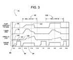
- FIG. 3is a stored data record of digital values that reflect the pumping operations of a vehicle at multiple well sites.
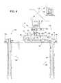
- FIG. 4is similar to FIG. 1, but showing another embodiment of a vehicle's pumping operations at a third well site.
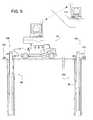
- FIG. 5is similar to FIG. 4, but showing the vehicle pumping fluid at a fourth well site.
- FIG. 6is a stored data record of digital values that reflect the pumping operations of a vehicle at the well sites of FIGS. 4 and 5.
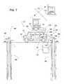
- FIG. 7is a schematic diagram showing a vehicle pumping oil from a tank battery.
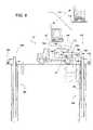
- FIG. 8is a schematic diagram showing the vehicle of FIG. 7 pumping hot oil down into a well at a well site.
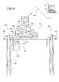
- FIG. 9is a schematic diagram showing the vehicle of FIG. 7 circulating hot oil through a tank battery at another well site.
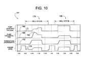
- FIG. 10is a stored data record of digital values that reflect the pumping operations illustrated in FIGS. 7, 8 and 9 .
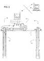
- FIGS. 1 and 2illustrate a vehicle 10 for servicing a first well 12 at a first well site 14 and a second well 16 at a second well site 18 .
- the two well sites 14 and 18are remote in that they are miles apart from each other and miles apart from a main office 20 .
- Wells 14 and 18each include a string of tubing 22 disposed within a string of casing 24 .
- Petroleum, water, gas or other ground-source fluidpasses through openings in casing 24 to enter an annulus 26 between the inner wall of casing 24 and the outer wall of tubing 22 . From annulus 26 , the fluid is then pumped or otherwise forced upward through the interior of tubing 22 , so the fluid can be extracted at ground level for later use or processing.
- an end cap 28may be temporarily installed at the upper end of tubing 22 .
- a servicing fluidcan be forced through annulus 26 and/or tubing 22 .
- a pump 32 on vehicle 10can force the servicing fluid into the well via an annulus valve 34 open to annulus 26 or a tubing valve 36 open to tubing 22 .
- Vehicle 10is schematically illustrated to represent any fluid-pumping vehicle, examples of which include, but are not limited to, a tanker truck, fluid pumping truck, kill truck, chemical truck, treating truck, and hot oil truck.
- Vehicle 10includes at least one tank for holding a fluid and at least one pump for pumping the fluid.
- Examples of the fluid being pumpedinclude, but are not limited to, water (pure or with some additives), hot oil, fuel to power vehicle 10 (e.g., gasoline or diesel fuel), a scale inhibitor (e.g., DynoChem 1100 by DynoChem of Midland, Tex.), an emulsion breaker (e.g., DynoChem 5400 by DynoChem), a bactericide (e.g., DynoCide #4 by DynoChem), paraffin dispersant (e.g., CynoChem 7498 by DynoChem), and an antifoaming agent (e.g., DynoChem 4690 by DynoChem).
- a scale inhibitore.g., DynoChem 1100 by DynoChem of Midland, Tex.
- an emulsion breakere.g., DynoChem 5400 by DynoChem
- a bactericidee.g., Dyno
- vehicle 10includes a first tank 38 for water 40 , a second tank 42 for a paraffin dispersant 44 , a third tank 46 for a scale inhibitor 48 , a fourth tank 50 for a bactericide 52 , and a fuel tank 54 for fuel 56 to power an engine 58 of vehicle 10 .
- Engine 58is coupled to power drive wheels 60 of vehicle 10 and is further coupled to drive pump 32 , which is adapted to selectively pump fluids 40 , 44 , 48 and 52 into a well.
- Valves 39 , 43 , 47 and 51allow pump 32 to selectively draw fluid from tanks 38 , 42 , 46 and 50 respectively.
- a fuel pump 60pumps fuel 56 from tank 54 to engine 58 , which allows vehicle 10 to drive between well sites and power pump 32 .
- Vehicle 10carries an electrical data storage device, such as a data collector 62 that receives input signals from various feedback devices for monitoring the operations of vehicle 10 .
- Data collector 62is schematically illustrated to include any device for collecting, manipulating, converting, transferring and/or storing digital data. Examples of data collector 62 include, but are not limited to, a personal computer, PC, desktop computer, laptop, notebook, PLC (programmable logic controller), data logger, etc.
- Examples of the various feedback devicesinclude, but are not limited to, a pump discharge pressure sensor 64 ; a pump discharge flow meter 66 ; an annulus pressure sensor 68 , a tachometer 70 (i.e., any device that provides a signal useful in determining a relative speed of engine 58 ); and a counter 72 that indicates the strokes per minute of a reciprocating pump, such as pump 32 .
- Feedback devices 64 , 66 , 68 and 72are examples of devices that sense a variable associated with the fluid being pumped, wherein examples of the variable include, but are not limited to pressure, temperature and flow rate. It should be noted that vehicle 10 could have more or less than the feedback devices just mentioned and still remain well within the scope of the invention.
- counter 72 and flow meter 66both can provide data collector 62 with an indication of the flow rate of pump 32 , so if sensing the flow rate is desired, really only one of counter 72 and flow meter 66 would be needed.
- additional feedback devicessuch as limit switches, could sense the open/closed position of valves 39 , 43 , 47 and 51 and provide data collector 62 with an indication of which fluid pump 32 is pumping.
- vehicle 10may travel from a contractor's home base to well 12 to pump water 40 from tank 38 down into tubing 22 and back up through annulus 26 .
- Such an operationis often referred to as, “killing the well” and is used for preparing the well for further maintenance work and/or for checking the well for leaks or flow blockages.
- vehicle 10may travel to well 16 for a similar killing operation.
- vehicle 10returns to the contractor's home base.
- data collector 62 and feedback devices 64 , 66 , 68 , 70 and 72the vehicle's sequence of operations for the day is recorded as a stored data record 74 .
- the stored data record 74comprises various digital values representative of the variable associated with the fluid being pumped, the time of day that the fluid is being pumped, the speed of engine 58 , and a well site identifier that indicates at which well vehicle 10 was operating.
- the stored data record 74can be displayed in various formats such as a tabulation of digital values and/or corresponding graphical format, as shown in FIG. 3 .
- the graphical format of data record 74provides plots of certain key variables as a function of the time of day that the variables were sampled.
- the plotted variablesare pump strokes per minutes 76 , as sensed by counter 72 ; tubing pressure 78 , as sensed by pressure sensor 64 ; annulus pressure 80 , as sensed by pressure sensor 68 ; and RPM 82 (revolutions per minute) of engine 58 , as measured by tachometer 70 .
- Variables 76 , 78 , 80 and 82are plotted with reference to a common X-axis 84 representing the time of day.
- the displayed plots and values of FIG. 3comprise one example of a stored data record 74 , which is stored by data collector 62 .
- All the values of stored data record 74are preferably digital for ease of manipulation and storage by data collector 62 .
- input from feedback devices 64 , 66 , 68 , 70 and 72may originate as analog signals, a conventional A/D converter (in the form of a separate circuit or incorporated into data collector 62 ) converts the signals to digital ones, so the digital values can be readily handled and stored by data collector 62 .
- a first well site identifier 90that identifies the well by name, description, or location is entered into data collector 62 by way of a key board 92 or by some other data input method.
- the well site identifiermay be the well's APIN (American Petroleum Institute Number), or some other identifier, such as, for example, “WELL SITE #1,” as shown in FIG. 3 .
- Numeral 94indicates engine 58 is idle between 9:10-9:30am, during which time workers are apparently setting up to kill well 12 .
- Setupmay involve connecting a hose 96 from a pump discharge valve 98 on vehicle 10 to tubing valve 36 on well 12 .
- Annulus valve 34may be partially opened to relieve fluid pressure building up due to pump 32 forcing water 40 into tubing 22 , which forces fluid upward through annulus 26 .
- Discharge 100 through valve 34is preferable directed to a holding tank (not shown).
- engine 58begins driving pump 32 , as indicated by the engine RPM 82 , pump strokes/min 76 , and tubing pressure 78 all increasing.
- Numeral 102indicates a generally constant flow rate between 10:00 and 11:30.
- Arrows 104 of FIG. 1indicate the general direction of fluid flow through tubing 22 and annulus 26 .
- the pressure in tubing 22peaks shortly after 10:00, and the pressure in annulus 26 peaks just before pump 32 is turned off at 11:30.
- the pressure of annulus 26 increasing while the pressure in tubing 22 decreasesis due to oil originally in tubing 22 being displaced by the heavier water 40 from tank 38 .
- tubing pressure 78drops off almost immediately; however, annulus pressure 80 decreases more slowly, because the standing head of water in tubing 22 continues to apply pressure to fluid in annulus 26 which now contains a higher percentage of relatively light oil. From 11:30 to 12:30, vehicle 10 is inactive, which can mean the crew working on well 12 is taking a lunch break or preparing to leave well site 14 .
- the RPM of engine 58increases with no sign of any pumping, which indicates that vehicle 10 is traveling to another well site.
- the crew of vehicle 10enters into data collector 62 a second well site identifier 106 to indicate they have arrived at well site 18 .
- Equipment setupoccurs between 1:30 and 2:00, and pumping runs from 2:00 to 4:00.
- Plots 76 , 78 , 80 and 82show that the pumping process at well site 18 is similar to that at well site 14 .
- the pump strokes/min 76is higher, while the tubing pressure 78 and the annulus pressure 80 is lower than what was experienced at well site 14 . This could indicate that well 12 is deeper and/or provides more flow resistance than well 16 .
- the plotsindicate a period of equipment inactivity between 4:00 and 4:30.
- the engine RPM curve 82indicates a short period of engine idling before vehicle 10 travels about 30 minutes back to the contractor's home base for an arrival time of about 5:00.
- the contractorcan now determine the quantity of water that was pumped into wells 12 and 16 and charge the appropriate well owners accordingly.
- data collector 62includes communication equipment 108 (e.g., a modem, cell phone, etc.—all of which are schematically depicted as communication equipment 108 ).
- Communication equipment 108enables stored data record 74 to be transmitted via the Internet (or other communication system) over a wireless communication link 110 (e.g., airwaves, satellite, etc.) to a computer 112 at a location remote relative to well sites 14 and 18 .
- Computer 112may be at the main office of the well owner or at the contractor's home base, so the owner or the contractor can monitor operations at the well site even though they may be miles from the site.
- wireless communication linkrefers to data being transmitted over a certain distance, wherein over that certain distance the data is transmitted through a medium of air and/or space rather than wires.
- Wireless communication link 110is schematically illustrated to represent a wide variety of systems that are well known to those skilled in the art of wireless communication.
- data record 74can be transferred over the Internet between data collector 62 and computer 112 .
- Data record 74can assume any of a variety of common formats including, but not limited to HTML, e-mail, and various other file formats that may depend on the particular software being used.
- a stored data record 74 ′comprises a first plot 118 of annulus pressure, as sensed by pressure sensor 68 , a second plot 120 of water flush, as measured in GPM by flow meter 66 when valve 39 is open, a third plot 122 (CHEM-A) of a first chemical of paraffin dispersant 44 , as measured in GPM by flow meter 66 when valve 43 is open; a fourth plot 124 (CHEM-B) of a second chemical of scale inhibitor 48 , as measured in GPM by flow meter 66 when valve 47 is open; a fifth plot 126 (CHEM-C) of a third chemical of bactericide 52 , as measured in GPM by flow meter 66 when valve 51 is open; and a sixth plot 128 of engine RPM.
- Stored data record oooindicates that vehicle 10 departs the contractor's home base at about 8:30 and arrives at a well site 130 at about 8:45. Upon arrival, a well site identifier 132 identifying a well 133 at a well site 130 is entered into data collector 62 .
- Equipment setupwhich occurs just before 9:00, involves connecting hose 96 from discharge valve 98 to annulus valve 34 , as shown in FIG. 4 . This allows water and the various chemicals to be selectively and sequentially pumped down into annulus 26 .
- valves 43 , 98 and 34are opened, valves 39 , 47 and 51 are closed, and the speed of engine 58 increases to drive pump 32 to pump CHEM-A from tank 42 down through annulus 26 .
- the pumpingcontinues for about twenty minutes, so the total amount of CHEM-A is determined by multiplying twenty minutes times the GPM reading of flow meter 66 .
- valve 43closes and valve 47 opens to pump CHEM-B from tank 46 down through annulus 26 ; again, for about twenty minutes.
- valve 47closes and valve 51 opens to pump CHEM-C from tank 50 down through annulus 26 .
- a water flushing processis performed from 10:00 to 11:00, wherein valve 39 is open and valves 43 , 47 and 51 are closed to pump water 40 from tank 38 into annulus 26 .
- the total amounts of water, CHEM-B, and CHEM-Ccan be determined in the same way as with CHEM-A. In an alternate embodiment, the total volume of water and chemical being pumped is measured directly, and the results are stored and displayed in gallons rather than gallons/minute.
- Stored data record 74 ′indicates that vehicle 10 is traveling from about 11:30 to 12:00, and equipment inactivity from 12:00 to 1:00 indicates a lunch break and/or equipment is being setup.
- a well site identifier 134 identifying another well 136 at another well site 138is entered into data collector 62 .
- Stored data record 74 ′indicates that vehicle 10 departs well site 138 at about 4:30 and arrives back at the contractor's home base at 5:00. As with the embodiment of FIGS. 1-3, stored data record 74 ′ can be transmitted via wireless communication link 110 from data collector 62 to remote computer 112 .
- a vehicle 10 ′provides a hot oil treatment for a well 140 at one well site 142 (FIGS. 7 and 8) and treats a tank battery 144 at another well site 146 (FIG. 9 ).
- Vehicle 10 ′comprises a tank 148 with a heater 150 for storing and heating oil 152 .
- Vehicle 10 ′also includes a piping system 154 through which oil is directed by valves 156 , 158 , 160 , 162 and 164 .
- FIG. 10illustrates a stored data record 74 ′′ that captures the activities of vehicle 10 ′ throughout a day.
- Data record 74 ′′includes a first plot 166 of pump strokes/min of a pump 32 ′; a second plot 168 of pump discharge pressure as sensed by pressure sensor 64 ; a third plot 170 of oil temperature, as sensed by a temperature sensor 172 , and a fifth plot 174 of the speed of engine 58 , as sensed by tachometer 70 .
- vehicle 10 ′drives to well site 142 from 8:15 to 9:00, and a well site identifier 176 is entered into data collector 62 .
- pump 32 ′draws oil 152 from a tank battery 178 (i.e., any vessel above or below ground for holding oil) through a hose connected to valve 162 .
- a tank battery 178i.e., any vessel above or below ground for holding oil
- Valves 164 , 160 and 156are closed, and valves 162 and 158 are open to direct oil in series through hose 80 , valve 162 , pump 32 ′, valve 158 and into tank 148 .
- heater 150heats oil 152 to a certain temperature, as sensed by temperature sensor 172 .
- the setup of vehicle 10 ′is switched over, so hose 180 connects valve 160 to annulus valve 34 , as shown in FIG. 8 .
- oil 152reaches the proper temperature, and valves 156 , 160 and 34 are opened (valves 162 , 164 and 158 are closed) to allow pump 32 ′ to force the heated oil 152 down through annulus 26 .
- This pumping processruns till 11:30.
- a blockage in annulus 26caused the pump discharge pressure to be relatively high at first, as indicated by an initial hump 182 in plot 168 , but the pressure fell after the hot oil dissolved the obstruction.
- vehicle 10 ′is disconnected from well 140 , and the service crew breaks for lunch.
- vehicle 10 ′departs well site 142 , arrives at a well 188 at well site 146 at 1:30, and an appropriate well site identifier 186 is entered into data collector 62 .
- vehicle 10 ′is setup at well site 146 , as shown in FIG. 9 .
- a suction hose 190runs between valve 162 and oil 152 ′ in tank battery 144
- a return hose 192extends between valve 164 and tank battery 144 .
- Valves 160 and 56are closed, and valves 162 , 164 and 158 are opened to circulate oil in series through suction hose 190 , valve 162 , pump 32 ′, valve 158 , tank 148 , valve 164 , and return hose 192 .
- heater 150heats oil 152 ′ to a predetermined temperature.
- plot 168shows that the pump discharge pressure is significantly lower at 3:00 than at 10:30, which allows one to conclude that a well was being treated at well site 142 and that a tank battery was being treated at well site 146 .
- Stored data record 74 ′′indicates that vehicle 10 ′ departs well site 146 at about 4:30 and arrives back at the contractor's home base at 5:00. Similar to certain other embodiments of the invention, stored data record 74 ′′ can be transmitted via wireless communication link 110 from data collector 62 to remote computer 112 .
Landscapes
- Geology (AREA)
- Physics & Mathematics (AREA)
- Life Sciences & Earth Sciences (AREA)
- Engineering & Computer Science (AREA)
- Mining & Mineral Resources (AREA)
- Environmental & Geological Engineering (AREA)
- Geophysics (AREA)
- Fluid Mechanics (AREA)
- Geochemistry & Mineralogy (AREA)
- General Life Sciences & Earth Sciences (AREA)
- Loading And Unloading Of Fuel Tanks Or Ships (AREA)
- Time Recorders, Dirve Recorders, Access Control (AREA)
- Arrangements For Transmission Of Measured Signals (AREA)
- Control Of Positive-Displacement Pumps (AREA)
- Pipeline Systems (AREA)
Abstract
Description
Claims (32)
Priority Applications (3)
| Application Number | Priority Date | Filing Date | Title |
|---|---|---|---|
| US09/945,924US6578634B2 (en) | 2001-09-05 | 2001-09-05 | Method of monitoring pumping operations of a service vehicle at a well site |
| CA002382630ACA2382630C (en) | 2001-09-05 | 2002-04-19 | A method of monitoring pumping operations of a service vehicle at a well site |
| US10/440,633US7064677B2 (en) | 2001-09-05 | 2003-05-19 | Method of monitoring service operations of a service vehicle at a well site |
Applications Claiming Priority (1)
| Application Number | Priority Date | Filing Date | Title |
|---|---|---|---|
| US09/945,924US6578634B2 (en) | 2001-09-05 | 2001-09-05 | Method of monitoring pumping operations of a service vehicle at a well site |
Related Child Applications (1)
| Application Number | Title | Priority Date | Filing Date |
|---|---|---|---|
| US10/440,633Continuation-In-PartUS7064677B2 (en) | 2001-09-05 | 2003-05-19 | Method of monitoring service operations of a service vehicle at a well site |
Publications (2)
| Publication Number | Publication Date |
|---|---|
| US20030042020A1 US20030042020A1 (en) | 2003-03-06 |
| US6578634B2true US6578634B2 (en) | 2003-06-17 |
Family
ID=25483715
Family Applications (2)
| Application Number | Title | Priority Date | Filing Date |
|---|---|---|---|
| US09/945,924Expired - LifetimeUS6578634B2 (en) | 2001-09-05 | 2001-09-05 | Method of monitoring pumping operations of a service vehicle at a well site |
| US10/440,633Expired - LifetimeUS7064677B2 (en) | 2001-09-05 | 2003-05-19 | Method of monitoring service operations of a service vehicle at a well site |
Family Applications After (1)
| Application Number | Title | Priority Date | Filing Date |
|---|---|---|---|
| US10/440,633Expired - LifetimeUS7064677B2 (en) | 2001-09-05 | 2003-05-19 | Method of monitoring service operations of a service vehicle at a well site |
Country Status (2)
| Country | Link |
|---|---|
| US (2) | US6578634B2 (en) |
| CA (1) | CA2382630C (en) |
Cited By (16)
| Publication number | Priority date | Publication date | Assignee | Title |
|---|---|---|---|---|
| US20030196798A1 (en)* | 2001-09-05 | 2003-10-23 | Key Energy Services, Inc. | Method of monitoring service operations of a service vehicle at a well site |
| US20050103491A1 (en)* | 2003-10-03 | 2005-05-19 | Key Energy Serivices, Inc. | Activity data capture system for a well service vehicle |
| US20060235741A1 (en)* | 2005-04-18 | 2006-10-19 | Dataforensics, Llc | Systems and methods for monitoring and reporting |
| US20070035413A1 (en)* | 2003-04-11 | 2007-02-15 | Vesa Uitto | System for managing borehole information |
| US20090055029A1 (en)* | 2007-04-09 | 2009-02-26 | Lufkin Industries, Inc. | Real-time onsite internet communication with well manager for constant well optimization |
| US20100127888A1 (en)* | 2008-11-26 | 2010-05-27 | Schlumberger Canada Limited | Using pocket device to survey, monitor, and control production data in real time |
| RU2412329C2 (en)* | 2005-09-13 | 2011-02-20 | Ки Энерджи Сервисиз, Инк. | Procedure for evaluation of characteristics of unit of installation for well repair by assessement of installation data |
| WO2011071479A1 (en)* | 2009-12-07 | 2011-06-16 | Halliburton Energy Services Inc. | System and method for remote well monitoring |
| US20110155461A1 (en)* | 2009-12-31 | 2011-06-30 | Nicholas Hutniak | System and apparatus for directing the drilling of a well |
| US20130261873A1 (en)* | 2010-11-25 | 2013-10-03 | The University Of Sydney | Apparatus and method for obtaining information from drilled holes for mining |
| US20140096832A1 (en)* | 2012-08-17 | 2014-04-10 | Lester James Thiessen | Dual Tank Structure Integrally Supported on a Portable Base Frame |
| US9458683B2 (en) | 2012-11-19 | 2016-10-04 | Key Energy Services, Llc | Mechanized and automated well service rig system |
| USD890211S1 (en) | 2018-01-11 | 2020-07-14 | Wayne/Scott Fetzer Company | Pump components |
| US10711788B2 (en) | 2015-12-17 | 2020-07-14 | Wayne/Scott Fetzer Company | Integrated sump pump controller with status notifications |
| USD893552S1 (en) | 2017-06-21 | 2020-08-18 | Wayne/Scott Fetzer Company | Pump components |
| US20240026875A1 (en)* | 2022-07-19 | 2024-01-25 | Caterpillar Inc. | Control of a dual-pump single-power source system |
Families Citing this family (37)
| Publication number | Priority date | Publication date | Assignee | Title |
|---|---|---|---|---|
| US7006009B2 (en) | 2002-04-01 | 2006-02-28 | Key Energy Services, Inc. | Servicing system for wells |
| US7221155B2 (en) | 2003-01-21 | 2007-05-22 | Key Energy Services, Inc. | Inventory counter for oil and gas wells |
| BRPI0407497A (en)* | 2003-02-14 | 2006-02-14 | Key Energy Servioces Inc | apparatus and method for monitoring air pressure in a probe clutch |
| AR048118A1 (en) | 2003-02-14 | 2006-04-05 | Key Energy Services Inc | APPARATUS AND METHOD TO MINIMIZE THE SLIPPING OF THE DRUM CLUTCH OF A WELL RECONDITIONING EQUIPMENT |
| US20040226712A1 (en)* | 2003-05-14 | 2004-11-18 | Hood John Charles | Portable memory device for mobile workover rig |
| MXPA06009268A (en)* | 2004-02-13 | 2007-02-21 | Rs Solutions Llc | Method and system for calculating and reporting slump in delivery vehicles. |
| WO2006021398A2 (en)* | 2004-08-27 | 2006-03-02 | Accenture Global Services Gmbh | Railcar transport telematics system |
| US20060133955A1 (en)* | 2004-12-17 | 2006-06-22 | Peters David W | Apparatus and method for delivering vapor phase reagent to a deposition chamber |
| GB2422389A (en)* | 2005-01-24 | 2006-07-26 | Strainstall Group Ltd | Ground engineering apparatus and method |
| US20070056727A1 (en)* | 2005-09-13 | 2007-03-15 | Key Energy Services, Inc. | Method and system for evaluating task completion times to data |
| EP1920965B1 (en)* | 2006-11-10 | 2011-06-29 | MONTALBANO TECHNOLOGY S.p.A. | Monitoring apparatus for tanks and the like |
| US7860593B2 (en) | 2007-05-10 | 2010-12-28 | Canrig Drilling Technology Ltd. | Well prog execution facilitation system and method |
| US8524321B2 (en)* | 2007-01-29 | 2013-09-03 | Praxair Technology, Inc. | Reagent dispensing apparatus and delivery method |
| US9518870B2 (en) | 2007-06-19 | 2016-12-13 | Verifi Llc | Wireless temperature sensor for concrete delivery vehicle |
| US8020431B2 (en) | 2007-06-19 | 2011-09-20 | Verifi, LLC | Method and system for calculating and reporting slump in delivery vehicles |
| US8989905B2 (en)* | 2007-06-19 | 2015-03-24 | Verifi Llc | Method and system for calculating and reporting slump in delivery vehicles |
| US8116936B2 (en)* | 2007-09-25 | 2012-02-14 | General Electric Company | Method and system for efficient data collection and storage |
| WO2010078350A1 (en)* | 2008-12-30 | 2010-07-08 | Kirk Hobbs | Mobile platform for monitoring a wellsite |
| US8417188B1 (en)* | 2009-02-03 | 2013-04-09 | Irobot Corporation | Systems and methods for inspection and communication in liquid petroleum product |
| US8857510B2 (en)* | 2009-04-03 | 2014-10-14 | Schlumberger Technology Corporation | System and method for determining movement of a drilling component in a wellbore |
| US9324049B2 (en)* | 2010-12-30 | 2016-04-26 | Schlumberger Technology Corporation | System and method for tracking wellsite equipment maintenance data |
| US10289668B2 (en)* | 2013-01-18 | 2019-05-14 | Landmark Graphics Corporation | System and method of populating a well log |
| US10969805B2 (en) | 2013-02-11 | 2021-04-06 | Graco Minnesota Inc. | Paint sprayer distributed control and output volume monitoring architectures |
| EP2954504A4 (en) | 2013-02-11 | 2016-10-12 | Graco Minnesota Inc | Remote monitoring for fluid applicator system |
| WO2016160458A1 (en) | 2015-03-30 | 2016-10-06 | Schlumberger Technology Corporation | Automated operation of wellsite equipment |
| CA2994227A1 (en) | 2015-09-02 | 2017-03-09 | Halliburton Energy Services, Inc. | Engine and transmission notification system using a j1939 data link interface |
| CA3090944A1 (en) | 2017-02-08 | 2018-08-16 | Upstream Data Inc. | Blockchain mine at oil or gas facility |
| CN108091111B (en)* | 2017-11-20 | 2018-11-13 | 淮阴工学院 | A kind of oil truck oil and gas leakage intelligent early-warning system |
| US11448202B2 (en) | 2018-01-23 | 2022-09-20 | Schlumberger Technology Corporation | Automated control of hydraulic fracturing pumps |
| CA3139776A1 (en) | 2019-05-15 | 2020-11-19 | Upstream Data Inc. | Portable blockchain mining system and methods of use |
| CA3076653A1 (en) | 2020-03-21 | 2021-09-21 | Upstream Data Inc. | Portable blockchain mining systems and methods of use |
| US11401797B1 (en) | 2021-10-08 | 2022-08-02 | Frederic M Newman | Electric well service rig for ESP installations |
| US11448050B1 (en) | 2021-10-08 | 2022-09-20 | Frederic M Newman | Universal electric well service rig |
| US11339612B1 (en) | 2021-10-08 | 2022-05-24 | Frederic M Newman | Electric well service rig |
| MX2023008154A (en)* | 2022-01-09 | 2023-07-21 | Gr Energy Services Man L P | WELL MONITORING SYSTEM WITH A WELL TRACKER AND METHOD OF USE THE SAME. |
| US11572260B1 (en)* | 2022-05-03 | 2023-02-07 | Frederic M Newman | Electric well service rig with speed limiter |
| US11674365B1 (en) | 2023-02-14 | 2023-06-13 | Frederic M Newman | Battery shuttle for electric well service rigs |
Citations (16)
| Publication number | Priority date | Publication date | Assignee | Title |
|---|---|---|---|---|
| US3760362A (en) | 1969-11-14 | 1973-09-18 | Halliburton Co | Oil field production automation method and apparatus |
| US3921152A (en) | 1972-06-01 | 1975-11-18 | Mobil Oil Corp | Automatic data retrieval system for pumping wells |
| US4187546A (en) | 1977-03-15 | 1980-02-05 | B. J. Hughes Inc. | Computer-controlled oil drilling rig having drawworks motor and brake control arrangement |
| US4393485A (en) | 1980-05-02 | 1983-07-12 | Baker International Corporation | Apparatus for compiling and monitoring subterranean well-test data |
| US4531204A (en) | 1972-05-04 | 1985-07-23 | Schlumberger Technology Corporation | Computerized truck instrumentation system |
| US4545017A (en) | 1982-03-22 | 1985-10-01 | Continental Emsco Company | Well drilling apparatus or the like with position monitoring system |
| US4604724A (en) | 1983-02-22 | 1986-08-05 | Gomelskoe Spetsialnoe Konstruktorsko-Tekhnologicheskoe Bjuro Seismicheskoi Tekhniki S Opytnym Proizvodstvom | Automated apparatus for handling elongated well elements such as pipes |
| US4794534A (en) | 1985-08-08 | 1988-12-27 | Amoco Corporation | Method of drilling a well utilizing predictive simulation with real time data |
| US4858130A (en)* | 1987-08-10 | 1989-08-15 | The Board Of Trustees Of The Leland Stanford Junior University | Estimation of hydraulic fracture geometry from pumping pressure measurements |
| US4916617A (en) | 1988-01-20 | 1990-04-10 | Delaware Capital Formation | Controller for well installations |
| US5051962A (en) | 1972-05-04 | 1991-09-24 | Schlumberger Technology Corporation | Computerized truck instrumentation system |
| US5132904A (en) | 1990-03-07 | 1992-07-21 | Lamp Lawrence R | Remote well head controller with secure communications port |
| US5216638A (en) | 1989-04-26 | 1993-06-01 | Schlumberger Technology Corporation | Method and apparatus for the acoustic investigation of a casing cemented in a borehole |
| US5237539A (en) | 1991-12-11 | 1993-08-17 | Selman Thomas H | System and method for processing and displaying well logging data during drilling |
| US5278549A (en) | 1992-05-01 | 1994-01-11 | Crawford James R | Wireline cycle life counter |
| US6079490A (en) | 1998-04-10 | 2000-06-27 | Newman; Frederic M. | Remotely accessible mobile repair unit for wells |
Family Cites Families (13)
| Publication number | Priority date | Publication date | Assignee | Title |
|---|---|---|---|---|
| US4765435A (en)* | 1985-08-06 | 1988-08-23 | Schlumberger Technology Corporation | Mobile well-logging laboratory |
| US4700142A (en)* | 1986-04-04 | 1987-10-13 | Vector Magnetics, Inc. | Method for determining the location of a deep-well casing by magnetic field sensing |
| US4884847A (en)* | 1988-02-19 | 1989-12-05 | Consolidation Coal Co. | Apparatus and method for mapping entry conditions in remote mining systems |
| US5218301A (en)* | 1991-10-04 | 1993-06-08 | Vector Magnetics | Method and apparatus for determining distance for magnetic and electric field measurements |
| US5298894A (en)* | 1992-06-17 | 1994-03-29 | Badger Meter, Inc. | Utility meter transponder/antenna assembly for underground installations |
| US5438329A (en)* | 1993-06-04 | 1995-08-01 | M & Fc Holding Company, Inc. | Duplex bi-directional multi-mode remote instrument reading and telemetry system |
| US5617084A (en)* | 1993-09-10 | 1997-04-01 | Sears; Lawrence M. | Apparatus for communicating utility usage-related information from a utility usage location to a utility usage registering device |
| US5917434A (en)* | 1995-06-15 | 1999-06-29 | Trimble Navigation Limited | Integrated taximeter/GPS position tracking system |
| US6021093A (en)* | 1997-05-14 | 2000-02-01 | Gas Research Institute | Transducer configuration having a multiple viewing position feature |
| US6006212A (en)* | 1997-09-17 | 1999-12-21 | Itron, Inc. | Time-of-use and demand metering in conditions of power outage with a mobile node |
| US6377189B1 (en)* | 1999-03-31 | 2002-04-23 | Frederic M. Newman | Oil well servicing system |
| US6826492B2 (en)* | 2001-04-23 | 2004-11-30 | Key Energy Services, Inc. | Method of managing a well file record at a well site |
| US6578634B2 (en)* | 2001-09-05 | 2003-06-17 | Key Energy Services, Inc. | Method of monitoring pumping operations of a service vehicle at a well site |
- 2001
- 2001-09-05USUS09/945,924patent/US6578634B2/ennot_activeExpired - Lifetime
- 2002
- 2002-04-19CACA002382630Apatent/CA2382630C/ennot_activeExpired - Lifetime
- 2003
- 2003-05-19USUS10/440,633patent/US7064677B2/ennot_activeExpired - Lifetime
Patent Citations (16)
| Publication number | Priority date | Publication date | Assignee | Title |
|---|---|---|---|---|
| US3760362A (en) | 1969-11-14 | 1973-09-18 | Halliburton Co | Oil field production automation method and apparatus |
| US5051962A (en) | 1972-05-04 | 1991-09-24 | Schlumberger Technology Corporation | Computerized truck instrumentation system |
| US4531204A (en) | 1972-05-04 | 1985-07-23 | Schlumberger Technology Corporation | Computerized truck instrumentation system |
| US3921152A (en) | 1972-06-01 | 1975-11-18 | Mobil Oil Corp | Automatic data retrieval system for pumping wells |
| US4187546A (en) | 1977-03-15 | 1980-02-05 | B. J. Hughes Inc. | Computer-controlled oil drilling rig having drawworks motor and brake control arrangement |
| US4393485A (en) | 1980-05-02 | 1983-07-12 | Baker International Corporation | Apparatus for compiling and monitoring subterranean well-test data |
| US4545017A (en) | 1982-03-22 | 1985-10-01 | Continental Emsco Company | Well drilling apparatus or the like with position monitoring system |
| US4604724A (en) | 1983-02-22 | 1986-08-05 | Gomelskoe Spetsialnoe Konstruktorsko-Tekhnologicheskoe Bjuro Seismicheskoi Tekhniki S Opytnym Proizvodstvom | Automated apparatus for handling elongated well elements such as pipes |
| US4794534A (en) | 1985-08-08 | 1988-12-27 | Amoco Corporation | Method of drilling a well utilizing predictive simulation with real time data |
| US4858130A (en)* | 1987-08-10 | 1989-08-15 | The Board Of Trustees Of The Leland Stanford Junior University | Estimation of hydraulic fracture geometry from pumping pressure measurements |
| US4916617A (en) | 1988-01-20 | 1990-04-10 | Delaware Capital Formation | Controller for well installations |
| US5216638A (en) | 1989-04-26 | 1993-06-01 | Schlumberger Technology Corporation | Method and apparatus for the acoustic investigation of a casing cemented in a borehole |
| US5132904A (en) | 1990-03-07 | 1992-07-21 | Lamp Lawrence R | Remote well head controller with secure communications port |
| US5237539A (en) | 1991-12-11 | 1993-08-17 | Selman Thomas H | System and method for processing and displaying well logging data during drilling |
| US5278549A (en) | 1992-05-01 | 1994-01-11 | Crawford James R | Wireline cycle life counter |
| US6079490A (en) | 1998-04-10 | 2000-06-27 | Newman; Frederic M. | Remotely accessible mobile repair unit for wells |
Cited By (36)
| Publication number | Priority date | Publication date | Assignee | Title |
|---|---|---|---|---|
| US20030196798A1 (en)* | 2001-09-05 | 2003-10-23 | Key Energy Services, Inc. | Method of monitoring service operations of a service vehicle at a well site |
| US7064677B2 (en)* | 2001-09-05 | 2006-06-20 | Key Energy Services, Inc. | Method of monitoring service operations of a service vehicle at a well site |
| US20070035413A1 (en)* | 2003-04-11 | 2007-02-15 | Vesa Uitto | System for managing borehole information |
| US7492279B2 (en)* | 2003-04-11 | 2009-02-17 | Sandvik Mining And Construction Oy | System for managing borehole information |
| US20050103491A1 (en)* | 2003-10-03 | 2005-05-19 | Key Energy Serivices, Inc. | Activity data capture system for a well service vehicle |
| US7006920B2 (en)* | 2003-10-03 | 2006-02-28 | Key Energy Services, Inc. | Activity data capture system for a well service vehicle |
| WO2005033907A3 (en)* | 2003-10-03 | 2006-05-11 | Key Energy Services Inc | Activity data capture system for a well service vehicle |
| RU2389871C2 (en)* | 2003-10-03 | 2010-05-20 | Ки Энерджи Сервисиз, Инк. | Well servicing method and movable transport vehicle for well servicing |
| US20060235741A1 (en)* | 2005-04-18 | 2006-10-19 | Dataforensics, Llc | Systems and methods for monitoring and reporting |
| RU2412329C2 (en)* | 2005-09-13 | 2011-02-20 | Ки Энерджи Сервисиз, Инк. | Procedure for evaluation of characteristics of unit of installation for well repair by assessement of installation data |
| US20090055029A1 (en)* | 2007-04-09 | 2009-02-26 | Lufkin Industries, Inc. | Real-time onsite internet communication with well manager for constant well optimization |
| US9013322B2 (en) | 2007-04-09 | 2015-04-21 | Lufkin Industries, Llc | Real-time onsite internet communication with well manager for constant well optimization |
| US20100127888A1 (en)* | 2008-11-26 | 2010-05-27 | Schlumberger Canada Limited | Using pocket device to survey, monitor, and control production data in real time |
| GB2482800A (en)* | 2009-12-07 | 2012-02-15 | Halliburton Energy Serv Inc | System and method for remote well monitoring |
| AU2009356274B2 (en)* | 2009-12-07 | 2014-01-09 | Halliburton Energy Services, Inc. | System and method for remote well monitoring |
| WO2011071479A1 (en)* | 2009-12-07 | 2011-06-16 | Halliburton Energy Services Inc. | System and method for remote well monitoring |
| GB2482800B (en)* | 2009-12-07 | 2015-07-22 | Halliburton Energy Services Inc | System and method for remote well monitoring |
| US20110155461A1 (en)* | 2009-12-31 | 2011-06-30 | Nicholas Hutniak | System and apparatus for directing the drilling of a well |
| US8381838B2 (en)* | 2009-12-31 | 2013-02-26 | Pason Systems Corp. | System and apparatus for directing the drilling of a well |
| US20130261873A1 (en)* | 2010-11-25 | 2013-10-03 | The University Of Sydney | Apparatus and method for obtaining information from drilled holes for mining |
| US20140096832A1 (en)* | 2012-08-17 | 2014-04-10 | Lester James Thiessen | Dual Tank Structure Integrally Supported on a Portable Base Frame |
| US9689248B2 (en)* | 2012-08-17 | 2017-06-27 | Bdc Capital Inc. | Dual tank structure integrally supported on a portable base frame |
| US9605498B2 (en) | 2012-11-19 | 2017-03-28 | Key Energy Services, Llc | Rod and tubular racking system |
| US9562406B2 (en) | 2012-11-19 | 2017-02-07 | Key Energy Services, Llc | Mechanized and automated well service rig |
| US9458683B2 (en) | 2012-11-19 | 2016-10-04 | Key Energy Services, Llc | Mechanized and automated well service rig system |
| US9611707B2 (en) | 2012-11-19 | 2017-04-04 | Key Energy Services, Llc | Tong system for tripping rods and tubulars |
| US9657538B2 (en) | 2012-11-19 | 2017-05-23 | Key Energy Services, Llc | Methods of mechanized and automated tripping of rods and tubulars |
| US9470050B2 (en) | 2012-11-19 | 2016-10-18 | Key Energy Services, Llc | Mechanized and automated catwalk system |
| US10711788B2 (en) | 2015-12-17 | 2020-07-14 | Wayne/Scott Fetzer Company | Integrated sump pump controller with status notifications |
| US11486401B2 (en) | 2015-12-17 | 2022-11-01 | Wayne/Scott Fetzer Company | Integrated sump pump controller with status notifications |
| USD893552S1 (en) | 2017-06-21 | 2020-08-18 | Wayne/Scott Fetzer Company | Pump components |
| USD1015378S1 (en) | 2017-06-21 | 2024-02-20 | Wayne/Scott Fetzer Company | Pump components |
| USD890211S1 (en) | 2018-01-11 | 2020-07-14 | Wayne/Scott Fetzer Company | Pump components |
| USD1014560S1 (en) | 2018-01-11 | 2024-02-13 | Wayne/Scott Fetzer Company | Pump components |
| US20240026875A1 (en)* | 2022-07-19 | 2024-01-25 | Caterpillar Inc. | Control of a dual-pump single-power source system |
| US12203459B2 (en)* | 2022-07-19 | 2025-01-21 | Caterpillar Inc. | Control of a dual-pump single-power source system |
Also Published As
| Publication number | Publication date |
|---|---|
| CA2382630C (en) | 2006-03-14 |
| US20030042020A1 (en) | 2003-03-06 |
| CA2382630A1 (en) | 2003-03-05 |
| US20030196798A1 (en) | 2003-10-23 |
| US7064677B2 (en) | 2006-06-20 |
Similar Documents
| Publication | Publication Date | Title |
|---|---|---|
| US6578634B2 (en) | Method of monitoring pumping operations of a service vehicle at a well site | |
| US10815118B2 (en) | Mobile distribution station having sensor communication lines routed with hoses | |
| US10705547B2 (en) | Mobile distribution station with guided wave radar fuel level sensors | |
| US10633243B2 (en) | Mobile distribution station | |
| RU2389871C2 (en) | Well servicing method and movable transport vehicle for well servicing | |
| US20170146189A1 (en) | Remote well servicing systems and methods | |
| US6728638B2 (en) | Method of monitoring operations of multiple service vehicles at a well site | |
| US20110128160A1 (en) | Method and system for operating a well service rig | |
| CA3018485A1 (en) | Remote well servicing systems and methods | |
| CA2491903A1 (en) | System and method for automating or metering fluid recovered at a well | |
| KR100689108B1 (en) | Automatic reservoir control system for real time monitoring | |
| US20030094419A1 (en) | Apparatus for cleaning and pressure testing hydraulic control systems | |
| CN110500074A (en) | An intelligent maintenance device for heavy oil and high waxy oil wells | |
| CN110485967A (en) | A kind of defroster of double medicament well mouth of oil well dosing pipelines and antifreeze method | |
| CN111794728B (en) | Intelligent interconnection type skid-mounted acid liquid high-pressure injection equipment and control method | |
| CN211422615U (en) | Polymer microsphere dosing device | |
| KR100567434B1 (en) | On-line monitoring system for rainwater pumping station | |
| CN209261970U (en) | Vehicle hydraulic plant failure detection system | |
| CN106401923B (en) | Control method for the pumping equipment of drill-hole pumping experiment | |
| CN112282703B (en) | Oil well wellhead dosing pipeline anti-freezing system and method | |
| CN105134576B (en) | A kind of drainage pumping plant water pump operation performance diagnogtics method and diagnostic device | |
| RU167488U1 (en) | MOBILE HORIZONTAL PUMP UNIT FOR EXPRESSIVE WELLS | |
| CN111502617A (en) | Long-term online intelligent blockage removing system for water injection well | |
| CN211314176U (en) | Underwater pressurization system | |
| CN207951205U (en) | A kind of oilfield chemical dosing hybrid system |
Legal Events
| Date | Code | Title | Description |
|---|---|---|---|
| AS | Assignment | Owner name:UNITRAK SERVICES, L.P., TEXAS Free format text:ASSIGNMENT OF ASSIGNORS INTEREST;ASSIGNOR:NEWMAN, FREDERIC M.;REEL/FRAME:013101/0796 Effective date:20020715 | |
| AS | Assignment | Owner name:PNC BANK, NATIONAL ASSOCIATION, PENNSYLVANIA Free format text:SECURITY AGREEMENT;ASSIGNOR:KEY ENERGY SERVICES, INC.;REEL/FRAME:013269/0063 Effective date:20020816 | |
| AS | Assignment | Owner name:KEY ENERGY SERVICES, INC., TEXAS Free format text:ASSIGNMENT OF ASSIGNORS INTEREST;ASSIGNOR:UNITRACK SERVICES, L.P.;REEL/FRAME:013774/0865 Effective date:20030214 | |
| AS | Assignment | Owner name:PNC BANK, NATIONAL ASSOCIATION, PENNSYLVANIA Free format text:SECURITY INTEREST;ASSIGNORS:KEY ENERGY SERVICES, INC.;BROOKS WELL SERVICING, INC.;DAWSON PRODUCTION ACQUISITION CORP.;AND OTHERS;REEL/FRAME:014059/0689;SIGNING DATES FROM 20020416 TO 20030416 | |
| STCF | Information on status: patent grant | Free format text:PATENTED CASE | |
| AS | Assignment | Owner name:PNC BANK, NATIONAL ASSOCIATION, PENNSYLVANIA Free format text:SECURITY INTEREST;ASSIGNORS:KEY ENERGY SERVICES, INC.;BROOKS WELL SERVICING, INC.;DAWSON PRODUCTION ACQUISITION CORP.;AND OTHERS;REEL/FRAME:014119/0460 Effective date:20031110 | |
| AS | Assignment | Owner name:LEHMAN COMMERCIAL PAPER INC., AS COLLATERAL AGENT, Free format text:SECURITY AGREEMENT;ASSIGNOR:KEY ENERGY SERVICES, INC.;REEL/FRAME:016427/0646 Effective date:20050729 | |
| FPAY | Fee payment | Year of fee payment:4 | |
| AS | Assignment | Owner name:BANK OF AMERICA, NA, ILLINOIS Free format text:SECURITY AGREEMENT;ASSIGNOR:KEY ENERGY SERVICES, INC;REEL/FRAME:020317/0903 Effective date:20071129 Owner name:KEY ENERGY SERVICES, INC., TEXAS Free format text:RELEASE BY SECURED PARTY;ASSIGNOR:LEHMAN COMMERCIAL PAPER, INC.;REEL/FRAME:020325/0209 Effective date:20071128 Owner name:BANK OF AMERICA, NA,ILLINOIS Free format text:SECURITY AGREEMENT;ASSIGNOR:KEY ENERGY SERVICES, INC;REEL/FRAME:020317/0903 Effective date:20071129 | |
| AS | Assignment | Owner name:KEY ENERGY SERVICES, LLC,TEXAS Free format text:ASSIGNMENT OF ASSIGNORS INTEREST;ASSIGNOR:KEY ENERGY SERVICES, INC.;REEL/FRAME:024505/0957 Effective date:20100601 Owner name:KEY ENERGY SERVICES, LLC, TEXAS Free format text:ASSIGNMENT OF ASSIGNORS INTEREST;ASSIGNOR:KEY ENERGY SERVICES, INC.;REEL/FRAME:024505/0957 Effective date:20100601 | |
| FPAY | Fee payment | Year of fee payment:8 | |
| AS | Assignment | Owner name:BANK OF AMERICA, N.A., TEXAS Free format text:SECURITY AGREEMENT;ASSIGNOR:KEY ENERGY SERVICES, LLC;REEL/FRAME:024906/0588 Effective date:20100826 | |
| AS | Assignment | Owner name:KEY ENERGY SERVICES, INC., TEXAS Free format text:RELEASE BY SECURED PARTY;ASSIGNOR:BANK OF AMERICA, N.A.;REEL/FRAME:026064/0706 Effective date:20110331 | |
| FPAY | Fee payment | Year of fee payment:12 | |
| AS | Assignment | Owner name:CORTLAND CAPITAL MARKET SERVICES LLC, AS AGENT, IL Free format text:SECURITY INTEREST;ASSIGNOR:KEY ENERGY SERVICES, LLC;REEL/FRAME:035801/0073 Effective date:20150601 | |
| AS | Assignment | Owner name:BANK OF AMERICA, N.A., AS ADMINISTRATIVE AGENT, TE Free format text:SECURITY INTEREST;ASSIGNOR:KEYSTONE ENERGY SERVICES, LLC;REEL/FRAME:035814/0158 Effective date:20150601 | |
| AS | Assignment | Owner name:BANK OF AMERICA, N.A., AS ADMINISTRATIVE AGENT, TE Free format text:CORRECTIVE ASSIGNMENT TO CORRECT THE ASSIGNOR NAME PREVIOUSLY RECORDED AT REEL: 035814 FRAME: 0158. ASSIGNOR(S) HEREBY CONFIRMS THE SECURITY INTEREST;ASSIGNOR:KEY ENERGY SERVICES, LLC;REEL/FRAME:036284/0840 Effective date:20150601 | |
| AS | Assignment | Owner name:CORTLAND PRODUCTS CORP., AS AGENT, ILLINOIS Free format text:SECURITY INTEREST;ASSIGNOR:KEY ENERGY SERVICES, LLC;REEL/FRAME:040965/0383 Effective date:20161215 Owner name:BANK OF AMERICA, N.A., AS ADMINISTRATIVE AGENT, TE Free format text:SECURITY INTEREST;ASSIGNOR:KEY ENERGY SERVICES, LLC;REEL/FRAME:040989/0070 Effective date:20161215 Owner name:KEY ENERGY SERVICES, LLC, TEXAS Free format text:RELEASE BY SECURED PARTY;ASSIGNOR:BANK OF AMERICA, N.A.;REEL/FRAME:040995/0825 Effective date:20161215 | |
| AS | Assignment | Owner name:KEY ENERGY SERVICES, LLC, TEXAS Free format text:RELEASE BY SECURED PARTY;ASSIGNOR:CORTLAND CAPITAL MARKET SERVICES LLC;REEL/FRAME:040996/0899 Effective date:20151215 |