US6577888B1 - Sliding-dome and split-top MRI radio frequency quadrature array coil system - Google Patents
Sliding-dome and split-top MRI radio frequency quadrature array coil systemDownload PDFInfo
- Publication number
- US6577888B1 US6577888B1US09/676,225US67622500AUS6577888B1US 6577888 B1US6577888 B1US 6577888B1US 67622500 AUS67622500 AUS 67622500AUS 6577888 B1US6577888 B1US 6577888B1
- Authority
- US
- United States
- Prior art keywords
- coil
- neck
- head
- torso
- anterior
- Prior art date
- Legal status (The legal status is an assumption and is not a legal conclusion. Google has not performed a legal analysis and makes no representation as to the accuracy of the status listed.)
- Expired - Lifetime, expires
Links
Images


Classifications
- G—PHYSICS
- G01—MEASURING; TESTING
- G01R—MEASURING ELECTRIC VARIABLES; MEASURING MAGNETIC VARIABLES
- G01R33/00—Arrangements or instruments for measuring magnetic variables
- G01R33/20—Arrangements or instruments for measuring magnetic variables involving magnetic resonance
- G01R33/28—Details of apparatus provided for in groups G01R33/44 - G01R33/64
- G01R33/32—Excitation or detection systems, e.g. using radio frequency signals
- G01R33/34—Constructional details, e.g. resonators, specially adapted to MR
- G01R33/341—Constructional details, e.g. resonators, specially adapted to MR comprising surface coils
- G01R33/3415—Constructional details, e.g. resonators, specially adapted to MR comprising surface coils comprising arrays of sub-coils, i.e. phased-array coils with flexible receiver channels
- A—HUMAN NECESSITIES
- A61—MEDICAL OR VETERINARY SCIENCE; HYGIENE
- A61B—DIAGNOSIS; SURGERY; IDENTIFICATION
- A61B5/00—Measuring for diagnostic purposes; Identification of persons
- A61B5/05—Detecting, measuring or recording for diagnosis by means of electric currents or magnetic fields; Measuring using microwaves or radio waves
- A61B5/055—Detecting, measuring or recording for diagnosis by means of electric currents or magnetic fields; Measuring using microwaves or radio waves involving electronic [EMR] or nuclear [NMR] magnetic resonance, e.g. magnetic resonance imaging
- A—HUMAN NECESSITIES
- A61—MEDICAL OR VETERINARY SCIENCE; HYGIENE
- A61B—DIAGNOSIS; SURGERY; IDENTIFICATION
- A61B5/00—Measuring for diagnostic purposes; Identification of persons
- A61B5/70—Means for positioning the patient in relation to the detecting, measuring or recording means
- A61B5/702—Posture restraints
Definitions
- This inventionrelates to magnetic resonance imaging (MRI) systems, and particularly to the radio-frequency (RF) coils used in such systems.
- MRImagnetic resonance imaging
- RFradio-frequency
- MRIutilizes hydrogen nuclear spins of the water molecules in organic tissue, which are polarized by a strong, uniform, static magnetic field of a magnet (named B 0 —the main magnetic field in MRI physics).
- B 0the main magnetic field in MRI physics.
- the magnetically polarized nuclear spinsgenerate magnetic moments in the tissue.
- the magnetic momentspoint in the direction of the main magnetic field in a steady state, and produce no useful information if they are not disturbed by any excitation.
- the generation of a nuclear magnetic resonance (NMR) signal for MRI data acquisitionis accomplished by exciting the magnetic moments with a uniform RF magnetic field (named B 1 —the excitation field).
- B 1a uniform RF magnetic field
- the B 1 fieldis produced in the imaging region of interest by an RF transmit coil which is driven by a computer-controlled RF transmitter with a power amplifier.
- the nuclear spin systemabsorbs magnetic energy, and it's magnetic moments precess around the direction of the main magnetic field. After excitation, the precessing magnetic moments will go through a process of free induction decay, releasing their absorbed energy and returning to the steady state.
- free induction decayNMR signals are detected by the use of a receive RF coil, which is placed in the vicinity of the excited volume of the tissue.
- the NMR signalis the secondary electrical voltage (or current) in the receive RF coil that has been induced by the precessing magnetic moments of the tissue.
- the receive RF coilcan be either the transmit coil itself, or an independent receive-only RF coil.
- the NMR signalis used for producing MR images by using additional pulsed magnetic gradient fields, which are generated by gradient coils integrated inside the main magnet system.
- the gradient fieldsare used to spatially encode the signals and selectively excite a specific volume of the human body. There are usually three sets of gradient coils in a standard MRI system, which generate magnetic fields in the same direction of the main magnetic field, varying linearly in the imaging volume.
- the excitation and receptionIn MRI, it is desirable for the excitation and reception to be spatially uniform in the imaging volume for better image uniformity.
- the best excitation field homogeneityis usually obtained by using a whole-body volume RF coil for transmission.
- the whole-body transmit coilis the largest RF coil in the system.
- a large coilhowever, produces lower signal-to-noise ratio (SNR or S/N) if it is also used for reception, mainly because of its greater distance from the signal-generating tissue being imaged. Since a high signal-to-noise ratio is desirable in MRI, special-purpose coils are used for reception to enhance the S/N ratio from the tissue volume of interest.
- the coil devicemay be mechanically designed to facilitate tissue sample (e.g., human body, animal, or other organic tissue) handling and comfort, and to provide a protective barrier between the tissue and the RF electronics.
- tissue samplee.g., human body, animal, or other organic tissue
- Another way to increase the SNRis by quadrature reception. In this method, NMR signals are detected in two orthogonal directions, which are in the transverse plane or perpendicular to the main magnetic field. The two signals are detected by two independent individual coils which cover the same volume of interest. With quadrature reception, the SNR can be increased by up to 2 over that of the individual linear coils.
- a neurovascular RF coilis used head, neck/c-spine and vascular imaging without repositioning the sample (e.g., a human patient).
- the coverage of a neurovascular coildepending on the usable imaging volume (e.g., a sphere of 45 to 50 cm in diameter), may be about 48 cm (from the top of the head to the aortic arch). It is desirable for the performance, i.e., signal-to-noise ratio (SNR) and image uniformity, of a neurovascular coil to be comparable to a conventional head coil for head imaging and to a stand-alone neck coil for neck/c-spine imaging.
- SNRsignal-to-noise ratio
- image uniformityof a neurovascular coil to be comparable to a conventional head coil for head imaging and to a stand-alone neck coil for neck/c-spine imaging.
- vascular imagingit is desirable for a neurovascular coil to be able to provide homogeneous images for coverage of the blood vessels from the circle of Will
- an asymmetric birdcage coil designhas been used.
- the anterior and posterior parts of a conventional birdcageHayes, U.S. Pat. No. 4,692,705
- head coilare extended further over the neck and chest regions to cover these regions.
- the asymmetric birdcage coilis operated in quadrature mode for head and neck imaging.
- a quadrature RF coilhas also been implemented by (Misic, et al., U.S. Pat. No. 5,517,120) for neurovascular imaging and spectroscopy of the human anatomy.
- This neurovascular coilutilizes multiple horizontal conductors and end conductors to distribute the current such that two orthogonal magnetic modes, i.e., one horizontal field and one vertical field, are created by the coil to achieve the quadrature detection of magnetic resonance signal.
- the neurovascular coilis separated into two shells: an upper shell for the anterior conductors and a lower shell for the posterior conductors. These two shells are connected by a hinge at the middle of the top end of the head coil mechanical housing.
- the development of array coil technologyallows one to image a large field-of-view (FOV) while maintaining the SNR characteristic of a small and conformal coil.
- a two channel (four linear coils) volume array coil for magnetic resonance angiography of the head and neckhas been built.
- the first channelis a four bar quadrature head coil consisting of two linear coils.
- Two Helmholtz type coilsform the second channel for covering the neck and chest.
- the two Helmholtz type coilsare arranged such that the magnetic fields generated by them are diagonally oriented and perpendicular to each other (i.e., a quadrature coil pair).
- the quadrature neck coilis attached to the quadrature head coil.
- Each of the two Helmholtz type neck coilsoverlaps with the head coil to minimize the inductive coupling between the head and neck coils, i.e., the neck coils are critically coupled to the head coil, to reduce the noise correlation caused by the cross-talk between the head and the neck coils.
- a split-top, four channel, birdcage type array coilhas also been developed (Srinvasan, et al., U.S. Pat. No. 5,664,568; U.S. Pat. No. 5,602,479) for head, neck and vascular imaging.
- This split-top head and neck coilconsists of a birdcage head coil and two distributed type (flat birdcage type) coils: one for the anterior neck-torso and the other for the posterior neck-torso.
- the quadrature signal obtained with the head coilis separated into two channel.
- the anterior and posterior neck-torso coilsform the other two channels.
- the housing of the head and neck coilis divided into two parts: the lower housing for the posterior one half of the head coil and the posterior neck-torso coil and the upper housing for the anterior one half of the head coil and the anterior neck-torso coil.
- the upper housingis removable, i.e., a split top.
- the upper housingis secured to the lower housing with a latch during imaging.
- the inductive coupling between the neck-torso coils and the head coilis minimized by overlapping the neck-torso coils with the head coil.
- an asymmetric birdcage head and neck coilenlarges the size of a conventional birdcage head coil to cover the neck region. This compromises the performance (i.e., SNR) of the head-section of the asymmetric birdcage coil as compared to a conventional birdcage head coil.
- the anterior neck-torso coil sectionis far away from a patient's chest (for most of the patient population) and its shape is not optimized to fit the human neck-chest contour.
- the performance of the neck-torso section of the asymmetric birdcage coilis lower than that of its head section.
- the SNRdrops quickly from the neck region to the chest region. This limits the coverage of the asymmetric birdcage coil to only the head and neck, not the aortic arch.
- the quadrature neurovascular coil designlike the asymmetric birdcage coil design mentioned above, also uses a big single coil for covering the entire FOV from the top of the head to the aortic arch.
- the anterior chest coil sectionis also attached to the anterior head coil and far away from a patient's chest (for most of the patient population). Therefore, this neurovascular coil also has the same weaknesses as those of the above asymmetric birdcage coil, for example: lower SNR for the head imaging as compared to a conventional quadrature head coil and imaging non-uniformity of the chest region due to the quick SNR drop-off in this region.
- the coverage of the two channel quadrature (four linear coil elements) volume array coilis only for the head and neck but not for the aortic arch.
- the quadrature head coilgenerates magnetic fields in both the horizontal and vertical directions but the quadrature neck coil produces magnetic fields in the diagonal directions.
- the B 1 fieldsthe magnetic fields generated by MRI RF coil
- the B 1 fields of the head regionand the B 1 fields of the neck region are not quadrature (i.e., not perpendicular to each other).
- the each of the two linear neck coil elementshas to be critically coupled to the two linear head coil elements simultaneously. This increases the complication of isolating the neck coil from the head coil and makes it less robust for manufacture.
- the anterior neck-torso coil of the four channel vascular coilis also attached to the anterior head coil and far away from a patient's chest (for most of the patient population).
- both the anterior and posterior neck-torso coilsare linear coils. These result in insufficient sensitivity/penetration in imaging the chest region and therefore, cause substantial image non-uniformity for vascular imaging from the circle of Willis to the aortic arch. Image intensity correction is needed to improve the image homogeneity.
- the decoupling of the multiple modes (i.e., multiple NMR frequencies) birdcage type anterior and posterior neck-torso coils from the multiple modes birdcage head coilis much more difficult than that between two single mode linear coils.
- the big split-top housingwhen being moved toward a patient's face, may cause some patients to feel threatened.
- the optimized birdcage array coilscan only cover the head and part of the neck but not the aortic arch. Furthermore, the multiple modes birdcage coil design makes it more difficult to decouple the array coils from each other. This reduces the flexibility of adding more coil elements to the birdcage array coils to extend its coverage to the aortic arch.
- An MRI array coil system for neurovascular and spine imaging of a humanincludes a neck coil having a split top; a dome-like head coil having a dome region, the head coil being slidable between a closed position adjacent to the neck coil and an open position spaced away from the neck coil; a posterior torso coil attached to the neck coil; and an anterior torso coil adapted to cooperate with the posterior coil.
- FIG. 1is a perspective view of a system according. to the invention in a typical operating position.
- FIG. 2is a perspective view of a system according to the invention in an open position for patient positioning.
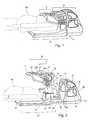
- FIG. 3is a perspective view of a sliding-dome head coil according to the invention.
- FIG. 4is a perspective view of a split-top neck coil with attached torso coils according to the invention.
- FIG. 5is a perspective view of a system according to the invention in a operating position typical for a large patient.
- FIG. 6is a perspective view of an additional embodiment of a system according to the invention.
- FIG. 7is a perspective view of another embodiment of a system according to the invention.
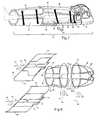
- FIG. 8is a schematic diagram of the electrical characteristics of a system according to the invention.
- FIG. 9is an enlarged view of the schematic diagram of the head coil portion of a system according to the invention.
- an MRI RF quadrature array coil system 2includes two sections: a head-neck section 3 and a torso section 4 .
- the head-neck section 3includes a sliding-dome head coil 5 and a split-top neck coil 6 .
- the section 3covers the head and the superior part of the neck of a human patient 80 .
- the torso section 4includes an anterior torso coil 7 and a posterior torso coil 8 .
- the torso section 4covers the inferior part of the neck and the torso of a human patient 80 .
- the sliding-dome head coil 5can be slid on a pair of sliding tracks 9 a, 9 b (see FIG. 3 ).
- Two latches 10 a , 10 b on the sliding-dome head coil 5are used to lock the sliding-dome head coil 5 in position when it is fully engaged with the split-top neck coil 6 , as shown in FIG. 1.
- a push button 11is used to release the latches 10 a , 10 b via an unshown mechanism to unlock the sliding-dome head coil 5 allowing the sliding-dome head coil 5 to slide to an open position as shown in FIG. 2 .
- the tracks 9 a , 9 bglide on unshown sleeves or other bearings in the head-neck section 3 .
- the split-top neck coil 6can be separated, at the middle of the neck coil housing, into an anterior neck coil 12 and a posterior neck coil 13 .
- An anterior torso coil 7is removably attachable to the anterior neck coil 12 as more fully described below.
- the anterior neck coil 12with or without the anterior torso coil 7 attached to it, is removable and is securable to the posterior neck coil housing 13 with a pair of latches 14 during imaging.
- the anterior torso coil 7may be attached to the anterior neck coil 12 with a pair of adjustable arms 25 a , 25 b as a part of a split-top anterior neck-torso coil 26 (see FIG. 2 ).
- the anterior torso coil 7can be moved up and down in the vertical direction using the adjustable arms 25 a , 25 b .
- the adjustable arms 25 a , 25 bcan be locked in multiple positions to hold the anterior torso coil just above the chest of the patient 80 .
- a sliding-joint 27allows the anterior torso coil 7 to be adjusted in the superior-inferior (i.e., head-toe) direction as well as to be tilted at an angle (e.g., approximately 0 to 30 degrees).
- the traveling distance, in the superior-inferior direction, of the anterior torso coil 7is designed to be enough to allow the anterior torso coil 7 to be moved clear of the anterior neck coil 12 so that the anterior torso coil 7 can be placed below (see FIG. 1) or above (see FIG. 5) the anterior neck coil 12 .
- the anterior torso coil 7is placed above the anterior neck coil 12 , as shown in FIG. 5 .
- the anterior torso coil 7is placed under the anterior neck coil 12 , as shown in FIG. 1 .
- window/openings 15 through 24there are ten windows/openings (reference numerals 15 through 24 ), including the opening 16 in the head-neck section 3 for the eyes of the patient 80 , i.e., an open design.
- an alternative embodiment of an anterior torso coil 28is substituted for the coil 7 described above.
- the anterior torso coil 28is a floating type coil design, i.e., the anterior torso coil 28 is placed directly on the chest of the patient 80 .
- the anterior torso coil 28may be, for example, secured to the posterior torso coil 8 with belts 29 (only one side shown) during imaging.
- the belts 29may, for example, attach with hook and loop fasteners.
- the anterior torso coil 28may be electrically connected to the circuitry of the posterior torso coil 8 via a coil cable 30 and a detachable connector 31 .
- the anterior torso coil 28may be removed when not being used. Similar to the anterior torso coil 7 , the coil 28 can also be placed on the top of the anterior neck coil 12 when imaging a large size patient.
- a patient 80may be positioned in the system 2 in the following manner.
- the sliding-dome head coil 5is slid away from the split-top neck coil 6 and the anterior neck coil 12 is also moved away to allow the patient 80 to lie down on a posterior coil housing 32 .
- the patientis cushioned by a pad 33 which serves for 1) patient comfort, 2) preventing the hair of the patient 80 from falling into the gap below a head-rest 34 and 3) reducing the movement of the head of the patient 80 during imaging.
- the anterior neck coil 12is connected to the posterior neck coil 13 so that the male connectors 90 of the anterior neck coil 12 properly engage into the female connectors 91 of the posterior neck coil 13 and the engagement is secured by the pair of latches 14 .
- the position of the anterior torso coil 7is adjusted (i.e., the vertical position, the superior-inferior position and the tilting angle) to keep it close to the chest of the patient 80 and also following the chest contour of the patient 80 as well.
- the sliding-dome head coil 5is closed by sliding the sliding-dome head coil 5 toward the split-top neck coil 6 until the latches 10 a , 10 b lock the sliding-dome head coil 5 in the closed position.
- the posterior torso coil 8may be provided with a connector panel 36 at the end of the posterior torso coil 8 that is normally covered by a cover 35 that may be removed to provide access to the connector panel 36 .
- An additional coil section 38may then be attached to the posterior torso coil 8 to extend the coverage of the system 2 to the thoracic and lumber spine.
- a similar designcan also be implemented for an anterior torso coil, i.e., replace the short anterior torso coil 7 or coil 28 with a longer anterior torso coil 39 , to extend the vascular imaging to the abdomen region.
- PVperipheral vascular
- the electrical arrangement of the system 2includes, for example, eight linear coils, including six saddle coils 40 , 41 , 42 , 43 , 44 , 45 and two loop coils 46 , 47 .
- the eight linear coilsform four quadrature coil pairs: one quadrature coil pair, coils 40 , 41 for the head, another quadrature coil pair, coils 42 , 43 for the neck, the third quadrature coil pair, coils 46 , 44 for the anterior torso and the fourth quadrature coil pair, coils 47 , 45 for the posterior torso.
- the eight coils 40 , 41 , 42 , 43 , 44 , 45 , 46 , 47can be used either as eight individual channels or as four quadrature channels 48 , 49 , 50 , 51 by combining each of the four quadrature coil pairs through a quadrature (i.e., 90 degree) combiner 52 , 53 , 54 , 55 , respectively.
- a quadraturei.e., 90 degree
- both the head channel 48 and the neck channel 49are turned on to receive the MRI signal.
- the neck channel 49 and the anterior torso channel 50 and the posterior torso channel 51are used.
- the neck channel 49 and the posterior torso channel 51are the choice for c-spine imaging.
- MRA of the blood vessels from the circle of Willis to the aortic archuses the head channel 48 , the neck channel 49 , the anterior torso channel 50 and the posterior torso channel 51 .
- a channelWhen a channel is not being used, it may be turned off using unshown active RF blocking circuitry (i.e., active decoupling chokes) or in the case of the floating type anterior torso coil 28 , the anterior torso coil 28 may be removed when not being used.
- the saddle coils 40 , 41may each be of similar or identical volume and perpendicularly oriented to each other to form the sliding-dome head coil 5 in the form of a dome-shaped cap. It may also be desirable to shape each of the saddle coils 40 , 41 such that the distance D 1 between pairs of returning conductor segments (segments 56 , 57 and segments 58 , 59 ) gradually reduces to D 2 as the segments reach the endrings 41 , 61 and the endrings 40 , 81 , respectively, such that D 2 is a fraction of D 1 . The fraction being, for example, between 0.60 and 0.85, with 0.75 being most desirable.
- the saddle coils 42 , 43may each be of similar or identical volume and perpendicularly oriented to each other to form the split-top neck coil 6 .
- a similar design as that used for the head coilis also applied to the saddle coils 42 , 43 for manipulating their shape: the diameter of the endring 62 at the neck region is smaller than the endring 63 at the head region.
- the diameter of the neck endring 62may be for example, 10 to 30 percent less than the diameter of the endring 63 at the head region, with 20 percent being most desirable.
- the separation between the pairs of returning conductors 64 , 65 underneath the neck of the patientmay be arranged to obtain good SNR for c-spine imaging.
- the saddle coil 44may be a semi-volume type saddle coil and the loop coil 46 a surface type loop coil to form the superior torso coil 7 .
- the size of its superior portioni.e., the portion close to the neck, may be enlarged so that it can provide better coverage for the neck.
- the left and right wings 66 , 67 of the saddle coil 44may be bent downward so that the penetration of the saddle coil 44 is improved.
- the shape of the anterior torso coil 12 at the neck regionmay be optimized for purposes of providing critical coupling between the neck coils and the anterior torso coils and covering more neck volume as well.
- the saddle coil 45may be a semi-volume type saddle coil and loop coil 47 a surface type loop coil to form the posterior torso coil 8 .
- the shape of the posterior torso coil 8 at the neck regionis also optimized for providing critical coupling between the neck and the posterior torso coils and covering more neck volume as well.
- the shape of the wings 68 , 69 of the saddle coil 45are gradually curved upward as the wings reach out so that the posterior saddle coil can cover deeper into the torso volume.
- the separation between the pair of the returning conductors 70 , 71 underneath the back of the patientis arranged to obtain good SNR for the spine imaging.
- anterior and posterior torso coilsare carefully manipulated so that these coils can cover deep into the torso volume but not cause isolation problem between the anterior and posterior torso coils.
- the direction of the magnetic field (i.e., B 1 field) generated by each of the eight coilsis either horizontal or vertical.
- the inductive isolation between two quadrature coilscan easily reach ⁇ 25 dB or better, including the situation for each pair of quadrature coils.
- the inductive coupling between two in-phase (i.e., the two B 1 fields are in same direction) neighboring coilsare minimized by the critical coupling of the two coils.
- the anterior torso coilsreach their best critical coupling position with the neck coils when they are moved to the most superior position. Moving the anterior torso coil toward the inferior direction and tilting the anterior torso coil can only have minor effect on the isolation between the anterior torso coil and the neck coil.
- the system 2 of the present inventionis more patient friendly.
- the open designresults in less claustrophobia.
- the smaller anterior neck coil housing, when moving toward a patient,causes less anxiety and is less threatening.
- the ability to place the anterior torso coil on top of the anterior neck coilallows the imaging of large patients up to 99 percentile of the patient population.
- the quadrature dome head coils and the neck coilsprovide superior SNR for the head (30% higher as compared to a commercial quadrature head coil) and neck (20% higher as compared to a commercial quadrature neck coil) imaging and good homogeneity as well.
- the image quality obtained with the quadrature array coil system of the present invention for the cervical and thoracic spineis comparable to that obtained with a commercial quadrature multiple channel CTL coil.
- the quadrature anterior and posterior coilsgain 20% higher SNR at the center of the torso volume compared to a pair of linear anterior and posterior loop coils.
- the image homogeneity for a large field-of-view (i.e., 48 cm) of the quadrature array coil system of the present inventionis much better than that of the prior art.
- the single mode quadrature array coil designmakes the inductive decoupling between two neighboring coils easier and simpler.
- the present inventionprovides a multiple channel RF quadrature combination array coil system that can be used as a head-only coil, a neck-only coil, a spine-only coil and also a large field-of-view (48 cm from the circle of Willis to the aortic arch) vascular coil in a single integrated system.
Landscapes
- Health & Medical Sciences (AREA)
- Physics & Mathematics (AREA)
- Life Sciences & Earth Sciences (AREA)
- Nuclear Medicine, Radiotherapy & Molecular Imaging (AREA)
- Engineering & Computer Science (AREA)
- Medical Informatics (AREA)
- Veterinary Medicine (AREA)
- Public Health (AREA)
- Biophysics (AREA)
- Pathology (AREA)
- General Health & Medical Sciences (AREA)
- Biomedical Technology (AREA)
- Heart & Thoracic Surgery (AREA)
- Animal Behavior & Ethology (AREA)
- Molecular Biology (AREA)
- Surgery (AREA)
- High Energy & Nuclear Physics (AREA)
- Condensed Matter Physics & Semiconductors (AREA)
- General Physics & Mathematics (AREA)
- Radiology & Medical Imaging (AREA)
- Physical Education & Sports Medicine (AREA)
- Magnetic Resonance Imaging Apparatus (AREA)
Abstract
Description
This invention relates to magnetic resonance imaging (MRI) systems, and particularly to the radio-frequency (RF) coils used in such systems.
MRI utilizes hydrogen nuclear spins of the water molecules in organic tissue, which are polarized by a strong, uniform, static magnetic field of a magnet (named B0—the main magnetic field in MRI physics). The magnetically polarized nuclear spins generate magnetic moments in the tissue. The magnetic moments point in the direction of the main magnetic field in a steady state, and produce no useful information if they are not disturbed by any excitation.
The generation of a nuclear magnetic resonance (NMR) signal for MRI data acquisition is accomplished by exciting the magnetic moments with a uniform RF magnetic field (named B1—the excitation field). The B1field is produced in the imaging region of interest by an RF transmit coil which is driven by a computer-controlled RF transmitter with a power amplifier. During excitation, the nuclear spin system absorbs magnetic energy, and it's magnetic moments precess around the direction of the main magnetic field. After excitation, the precessing magnetic moments will go through a process of free induction decay, releasing their absorbed energy and returning to the steady state. During free induction decay, NMR signals are detected by the use of a receive RF coil, which is placed in the vicinity of the excited volume of the tissue. The NMR signal is the secondary electrical voltage (or current) in the receive RF coil that has been induced by the precessing magnetic moments of the tissue. The receive RF coil can be either the transmit coil itself, or an independent receive-only RF coil. The NMR signal is used for producing MR images by using additional pulsed magnetic gradient fields, which are generated by gradient coils integrated inside the main magnet system. The gradient fields are used to spatially encode the signals and selectively excite a specific volume of the human body. There are usually three sets of gradient coils in a standard MRI system, which generate magnetic fields in the same direction of the main magnetic field, varying linearly in the imaging volume.
In MRI, it is desirable for the excitation and reception to be spatially uniform in the imaging volume for better image uniformity. In a standard MRI system, the best excitation field homogeneity is usually obtained by using a whole-body volume RF coil for transmission. The whole-body transmit coil is the largest RF coil in the system. A large coil, however, produces lower signal-to-noise ratio (SNR or S/N) if it is also used for reception, mainly because of its greater distance from the signal-generating tissue being imaged. Since a high signal-to-noise ratio is desirable in MRI, special-purpose coils are used for reception to enhance the S/N ratio from the tissue volume of interest.
It is desirable for specialty RF coil to have the following functional properties: high S/N ratio, good uniformity, high unloaded quality factor (Q) of the resonance circuit, and high ratio of the unloaded to loaded Q factors. In addition, the coil device may be mechanically designed to facilitate tissue sample (e.g., human body, animal, or other organic tissue) handling and comfort, and to provide a protective barrier between the tissue and the RF electronics. Another way to increase the SNR is by quadrature reception. In this method, NMR signals are detected in two orthogonal directions, which are in the transverse plane or perpendicular to the main magnetic field. The two signals are detected by two independent individual coils which cover the same volume of interest. With quadrature reception, the SNR can be increased by up to 2 over that of the individual linear coils.
In MRI and Magnetic Resonance Angiography (MRA), a neurovascular RF coil is used head, neck/c-spine and vascular imaging without repositioning the sample (e.g., a human patient). The coverage of a neurovascular coil, depending on the usable imaging volume (e.g., a sphere of 45 to 50 cm in diameter), may be about 48 cm (from the top of the head to the aortic arch). It is desirable for the performance, i.e., signal-to-noise ratio (SNR) and image uniformity, of a neurovascular coil to be comparable to a conventional head coil for head imaging and to a stand-alone neck coil for neck/c-spine imaging. For vascular imaging, it is desirable for a neurovascular coil to be able to provide homogeneous images for coverage of the blood vessels from the circle of Willis to the aortic arch for most of the patient population.
To cover the head and neck with a single RF coil, an asymmetric birdcage coil design has been used. In this design, the anterior and posterior parts of a conventional birdcage (Hayes, U.S. Pat. No. 4,692,705) head coil are extended further over the neck and chest regions to cover these regions. The asymmetric birdcage coil is operated in quadrature mode for head and neck imaging.
To further extend the coverage to the aortic arch, a quadrature RF coil has also been implemented by (Misic, et al., U.S. Pat. No. 5,517,120) for neurovascular imaging and spectroscopy of the human anatomy. This neurovascular coil utilizes multiple horizontal conductors and end conductors to distribute the current such that two orthogonal magnetic modes, i.e., one horizontal field and one vertical field, are created by the coil to achieve the quadrature detection of magnetic resonance signal. Mechanically, the neurovascular coil is separated into two shells: an upper shell for the anterior conductors and a lower shell for the posterior conductors. These two shells are connected by a hinge at the middle of the top end of the head coil mechanical housing.
The development of array coil technology (Roemer, et al., U.S. Pat. No. 4,825,162) allows one to image a large field-of-view (FOV) while maintaining the SNR characteristic of a small and conformal coil. Using this concept, a two channel (four linear coils) volume array coil for magnetic resonance angiography of the head and neck has been built. The first channel is a four bar quadrature head coil consisting of two linear coils. Two Helmholtz type coils form the second channel for covering the neck and chest. The two Helmholtz type coils are arranged such that the magnetic fields generated by them are diagonally oriented and perpendicular to each other (i.e., a quadrature coil pair). The quadrature neck coil is attached to the quadrature head coil. Each of the two Helmholtz type neck coils overlaps with the head coil to minimize the inductive coupling between the head and neck coils, i.e., the neck coils are critically coupled to the head coil, to reduce the noise correlation caused by the cross-talk between the head and the neck coils.
A split-top, four channel, birdcage type array coil has also been developed (Srinvasan, et al., U.S. Pat. No. 5,664,568; U.S. Pat. No. 5,602,479) for head, neck and vascular imaging. This split-top head and neck coil consists of a birdcage head coil and two distributed type (flat birdcage type) coils: one for the anterior neck-torso and the other for the posterior neck-torso. The quadrature signal obtained with the head coil is separated into two channel. The anterior and posterior neck-torso coils form the other two channels. The housing of the head and neck coil is divided into two parts: the lower housing for the posterior one half of the head coil and the posterior neck-torso coil and the upper housing for the anterior one half of the head coil and the anterior neck-torso coil. The upper housing is removable, i.e., a split top. The upper housing is secured to the lower housing with a latch during imaging. The inductive coupling between the neck-torso coils and the head coil is minimized by overlapping the neck-torso coils with the head coil.
It is known that significant gains in SNR (about 30%) can be achieved by using two short overlapping decoupled birdcage coils to cover the whole field-of-view compared to a single birdcage coil covering the same field-of-view. Converging the horizontal bars of the short birdcage coil, that covers the top part of the head, to a smaller endring, a further improvement in the SNR (about 40%) and better image homogeneity have been realized.
Employing an asymmetric birdcage head and neck coil enlarges the size of a conventional birdcage head coil to cover the neck region. This compromises the performance (i.e., SNR) of the head-section of the asymmetric birdcage coil as compared to a conventional birdcage head coil. The anterior neck-torso coil section is far away from a patient's chest (for most of the patient population) and its shape is not optimized to fit the human neck-chest contour. Thus, the performance of the neck-torso section of the asymmetric birdcage coil is lower than that of its head section. The SNR drops quickly from the neck region to the chest region. This limits the coverage of the asymmetric birdcage coil to only the head and neck, not the aortic arch.
The quadrature neurovascular coil design, like the asymmetric birdcage coil design mentioned above, also uses a big single coil for covering the entire FOV from the top of the head to the aortic arch. The anterior chest coil section is also attached to the anterior head coil and far away from a patient's chest (for most of the patient population). Therefore, this neurovascular coil also has the same weaknesses as those of the above asymmetric birdcage coil, for example: lower SNR for the head imaging as compared to a conventional quadrature head coil and imaging non-uniformity of the chest region due to the quick SNR drop-off in this region.
The coverage of the two channel quadrature (four linear coil elements) volume array coil is only for the head and neck but not for the aortic arch. The quadrature head coil generates magnetic fields in both the horizontal and vertical directions but the quadrature neck coil produces magnetic fields in the diagonal directions. In other words, the B1fields (the magnetic fields generated by MRI RF coil) of the head region and the B1fields of the neck region are not quadrature (i.e., not perpendicular to each other). Thus, the each of the two linear neck coil elements has to be critically coupled to the two linear head coil elements simultaneously. This increases the complication of isolating the neck coil from the head coil and makes it less robust for manufacture.
The anterior neck-torso coil of the four channel vascular coil is also attached to the anterior head coil and far away from a patient's chest (for most of the patient population). In addition, both the anterior and posterior neck-torso coils are linear coils. These result in insufficient sensitivity/penetration in imaging the chest region and therefore, cause substantial image non-uniformity for vascular imaging from the circle of Willis to the aortic arch. Image intensity correction is needed to improve the image homogeneity. The decoupling of the multiple modes (i.e., multiple NMR frequencies) birdcage type anterior and posterior neck-torso coils from the multiple modes birdcage head coil is much more difficult than that between two single mode linear coils. The big split-top housing, when being moved toward a patient's face, may cause some patients to feel threatened.
The major disadvantages of the above designs are 1) lower SNR for head imaging as compared to a conventional quadrature head coil, 2) for large field-of-view imaging, i.e., from the top of the head to the aortic arch, the image uniformity is not good due to rapid signal drop-off at the chest region and 3) lack of a capability of being used as a neck-only/c-spine-only coil.
The optimized birdcage array coils can only cover the head and part of the neck but not the aortic arch. Furthermore, the multiple modes birdcage coil design makes it more difficult to decouple the array coils from each other. This reduces the flexibility of adding more coil elements to the birdcage array coils to extend its coverage to the aortic arch.
An MRI array coil system for neurovascular and spine imaging of a human includes a neck coil having a split top; a dome-like head coil having a dome region, the head coil being slidable between a closed position adjacent to the neck coil and an open position spaced away from the neck coil; a posterior torso coil attached to the neck coil; and an anterior torso coil adapted to cooperate with the posterior coil.
FIG. 1 is a perspective view of a system according. to the invention in a typical operating position.
FIG. 2 is a perspective view of a system according to the invention in an open position for patient positioning.
FIG. 3 is a perspective view of a sliding-dome head coil according to the invention.
FIG. 4 is a perspective view of a split-top neck coil with attached torso coils according to the invention.
FIG. 5 is a perspective view of a system according to the invention in a operating position typical for a large patient.
FIG. 6 is a perspective view of an additional embodiment of a system according to the invention.
FIG. 7 is a perspective view of another embodiment of a system according to the invention.
FIG. 8 is a schematic diagram of the electrical characteristics of a system according to the invention.
FIG. 9 is an enlarged view of the schematic diagram of the head coil portion of a system according to the invention.
Referring to FIGS. 1 and 2, an MRI RF quadraturearray coil system 2 includes two sections: a head-neck section 3 and atorso section 4. The head-neck section 3, includes a sliding-dome head coil 5 and a split-top neck coil 6. Thesection 3 covers the head and the superior part of the neck of ahuman patient 80. Thetorso section 4, includes ananterior torso coil 7 and aposterior torso coil 8. Thetorso section 4 covers the inferior part of the neck and the torso of ahuman patient 80.
The sliding-dome head coil 5 can be slid on a pair of slidingtracks dome head coil 5 are used to lock the sliding-dome head coil 5 in position when it is fully engaged with the split-top neck coil 6, as shown in FIG. 1. Apush button 11 is used to release thelatches dome head coil 5 allowing the sliding-dome head coil 5 to slide to an open position as shown in FIG.2. Thetracks neck section 3.
The split-top neck coil 6 can be separated, at the middle of the neck coil housing, into ananterior neck coil 12 and aposterior neck coil 13. Ananterior torso coil 7 is removably attachable to theanterior neck coil 12 as more fully described below. Theanterior neck coil 12, with or without theanterior torso coil 7 attached to it, is removable and is securable to the posteriorneck coil housing 13 with a pair oflatches 14 during imaging.
Referring to FIG. 4, maleelectrical connectors 90 in theanterior neck coil 12 mate with female electrical connectors in theposterior neck coil 13. Theanterior torso coil 7 may be attached to theanterior neck coil 12 with a pair ofadjustable arms anterior torso coil 7 can be moved up and down in the vertical direction using theadjustable arms adjustable arms patient 80. A sliding-joint27 allows theanterior torso coil 7 to be adjusted in the superior-inferior (i.e., head-toe) direction as well as to be tilted at an angle (e.g., approximately 0 to 30 degrees). The traveling distance, in the superior-inferior direction, of theanterior torso coil 7 is designed to be enough to allow theanterior torso coil 7 to be moved clear of theanterior neck coil 12 so that theanterior torso coil 7 can be placed below (see FIG. 1) or above (see FIG. 5) theanterior neck coil 12. When imaging a large size patient (e.g., over 300 lb) theanterior torso coil 7 is placed above theanterior neck coil 12, as shown in FIG.5. For the smaller major patient population, theanterior torso coil 7 is placed under theanterior neck coil 12, as shown in FIG.1.
In this embodiment, there are ten windows/openings (reference numerals 15 through24), including theopening 16 in the head-neck section 3 for the eyes of thepatient 80, i.e., an open design.
Referring to FIG. 6, an alternative embodiment of ananterior torso coil 28 is substituted for thecoil 7 described above. Theanterior torso coil 28 is a floating type coil design, i.e., theanterior torso coil 28 is placed directly on the chest of thepatient 80. In this embodiment, theanterior torso coil 28 may be, for example, secured to theposterior torso coil 8 with belts29 (only one side shown) during imaging. Thebelts 29 may, for example, attach with hook and loop fasteners. Theanterior torso coil 28 may be electrically connected to the circuitry of theposterior torso coil 8 via acoil cable 30 and adetachable connector 31. Theanterior torso coil 28 may be removed when not being used. Similar to theanterior torso coil 7, thecoil 28 can also be placed on the top of theanterior neck coil 12 when imaging a large size patient.
Referring to FIG. 2, apatient 80 may be positioned in thesystem 2 in the following manner. The sliding-dome head coil 5 is slid away from the split-top neck coil 6 and theanterior neck coil 12 is also moved away to allow the patient80 to lie down on aposterior coil housing 32. The patient is cushioned by apad 33 which serves for 1) patient comfort, 2) preventing the hair of the patient80 from falling into the gap below a head-rest 34 and 3) reducing the movement of the head of the patient80 during imaging. After thepatient 80 is properly positioned on theposterior coil housing 32, theanterior neck coil 12 is connected to theposterior neck coil 13 so that themale connectors 90 of theanterior neck coil 12 properly engage into thefemale connectors 91 of theposterior neck coil 13 and the engagement is secured by the pair oflatches 14. Then the position of theanterior torso coil 7 is adjusted (i.e., the vertical position, the superior-inferior position and the tilting angle) to keep it close to the chest of thepatient 80 and also following the chest contour of the patient80 as well. Next, the sliding-dome head coil 5 is closed by sliding the sliding-dome head coil 5 toward the split-top neck coil 6 until thelatches dome head coil 5 in the closed position.
Referring to FIG. 7, in an additional embodiment of thesystem 2′, theposterior torso coil 8 may be provided with aconnector panel 36 at the end of theposterior torso coil 8 that is normally covered by acover 35 that may be removed to provide access to theconnector panel 36. Anadditional coil section 38 may then be attached to theposterior torso coil 8 to extend the coverage of thesystem 2 to the thoracic and lumber spine. A similar design can also be implemented for an anterior torso coil, i.e., replace the shortanterior torso coil 7 orcoil 28 with a longeranterior torso coil 39, to extend the vascular imaging to the abdomen region. Furthermore, by adding another peripheral vascular (PV) array coil section, coverage may be extended to the vascular imaging of the low extremities.
Referring to FIG. 8, the electrical arrangement of thesystem 2 includes, for example, eight linear coils, including six saddle coils40,41,42,43,44,45 and two loop coils46,47. The eight linear coils form four quadrature coil pairs: one quadrature coil pair, coils40,41 for the head, another quadrature coil pair, coils42,43 for the neck, the third quadrature coil pair, coils46,44 for the anterior torso and the fourth quadrature coil pair, coils47,45 for the posterior torso. The eight coils40,41,42,43,44,45,46,47 can be used either as eight individual channels or as fourquadrature channels combiner head channel 48 and theneck channel 49 are turned on to receive the MRI signal. To image the neck, theneck channel 49 and theanterior torso channel 50 and theposterior torso channel 51 are used. Theneck channel 49 and theposterior torso channel 51 are the choice for c-spine imaging. MRA of the blood vessels from the circle of Willis to the aortic arch uses thehead channel 48, theneck channel 49, theanterior torso channel 50 and theposterior torso channel 51. When a channel is not being used, it may be turned off using unshown active RF blocking circuitry (i.e., active decoupling chokes) or in the case of the floating typeanterior torso coil 28, theanterior torso coil 28 may be removed when not being used.
Referring to FIG. 9, the saddle coils40,41 may each be of similar or identical volume and perpendicularly oriented to each other to form the sliding-dome head coil 5 in the form of a dome-shaped cap. It may also be desirable to shape each of the saddle coils40,41 such that the distance D1 between pairs of returning conductor segments (segments segments 58,59) gradually reduces to D2 as the segments reach theendrings endrings
Referring to FIG. 8, the saddle coils42,43 may each be of similar or identical volume and perpendicularly oriented to each other to form the split-top neck coil 6. A similar design as that used for the head coil is also applied to the saddle coils42,43 for manipulating their shape: the diameter of theendring 62 at the neck region is smaller than theendring 63 at the head region. The diameter of theneck endring 62 may be for example, 10 to 30 percent less than the diameter of theendring 63 at the head region, with 20 percent being most desirable.
In addition, the separation between the pairs of returningconductors
Thesaddle coil 44 may be a semi-volume type saddle coil and the loop coil46 a surface type loop coil to form thesuperior torso coil 7. For theloop coil 46, the size of its superior portion, i.e., the portion close to the neck, may be enlarged so that it can provide better coverage for the neck. The left andright wings saddle coil 44 may be bent downward so that the penetration of thesaddle coil 44 is improved. Furthermore, the shape of theanterior torso coil 12 at the neck region may be optimized for purposes of providing critical coupling between the neck coils and the anterior torso coils and covering more neck volume as well.
Similarly, thesaddle coil 45 may be a semi-volume type saddle coil and loop coil47 a surface type loop coil to form theposterior torso coil 8. The shape of theposterior torso coil 8 at the neck region is also optimized for providing critical coupling between the neck and the posterior torso coils and covering more neck volume as well. The shape of thewings saddle coil 45 are gradually curved upward as the wings reach out so that the posterior saddle coil can cover deeper into the torso volume. The separation between the pair of the returningconductors
The size and the shape of the anterior and posterior torso coils are carefully manipulated so that these coils can cover deep into the torso volume but not cause isolation problem between the anterior and posterior torso coils.
The direction of the magnetic field (i.e., B1field) generated by each of the eight coils is either horizontal or vertical. The inductive isolation between two quadrature coils can easily reach −25 dB or better, including the situation for each pair of quadrature coils. The inductive coupling between two in-phase (i.e., the two B1fields are in same direction) neighboring coils are minimized by the critical coupling of the two coils. The anterior torso coils reach their best critical coupling position with the neck coils when they are moved to the most superior position. Moving the anterior torso coil toward the inferior direction and tilting the anterior torso coil can only have minor effect on the isolation between the anterior torso coil and the neck coil.
Thesystem 2 of the present invention is more patient friendly. The open design results in less claustrophobia. The smaller anterior neck coil housing, when moving toward a patient, causes less anxiety and is less threatening. The ability to place the anterior torso coil on top of the anterior neck coil allows the imaging of large patients up to 99 percentile of the patient population.
The quadrature dome head coils and the neck coils provide superior SNR for the head (30% higher as compared to a commercial quadrature head coil) and neck (20% higher as compared to a commercial quadrature neck coil) imaging and good homogeneity as well. The image quality obtained with the quadrature array coil system of the present invention for the cervical and thoracic spine is comparable to that obtained with a commercial quadrature multiple channel CTL coil. The quadrature anterior and posterior coils gain 20% higher SNR at the center of the torso volume compared to a pair of linear anterior and posterior loop coils. The image homogeneity for a large field-of-view (i.e., 48 cm) of the quadrature array coil system of the present invention is much better than that of the prior art.
In addition, the single mode quadrature array coil design makes the inductive decoupling between two neighboring coils easier and simpler.
The present invention provides a multiple channel RF quadrature combination array coil system that can be used as a head-only coil, a neck-only coil, a spine-only coil and also a large field-of-view (48 cm from the circle of Willis to the aortic arch) vascular coil in a single integrated system.
Claims (5)
1. An MRI array coil system for neurovascular and spine imaging of a human, said system comprising:
a neck coil having a split top;
a head coil having a dome region, said head coil being slidable between a closed position adjacent to said neck coil and an open position spaced away from said neck coil;
a posterior torso coil attached to said neck coil; and
an anterior torso coil adapted to cooperate with said posterior coil,
wherein said anterior torso coil is adjustably attached to said split top.
2. A system according toclaim 1 , wherein said anterior torso coil may be placed above or below said split top.
3. An MRI array coil system for neurovascular and spine imaging of a human, said system comprising:
a neck coil having a split top;
a head coil having a dome region, said head coil being slidable between a closed position adjacent to said neck coil and an open position spaced away from said neck coil;
a posterior torso coil attached to said neck coil; and
an anterior torso coil adapted to cooperate with said posterior coil,
wherein said anterior torso coil is a floating type coil.
4. An MRI array coil system for neurovascular and spine imaging of a human, said system comprising:
a neck coil having a split top;
a head coil having a dome region, said head coil being slidable between a closed position adjacent to said neck coil and an open position spaced away from said neck coil;
a posterior torso coil attached to said neck coil; and
an anterior torso coil adapted to cooperate with said posterior coil,
wherein:
the head coil is formed by a quadrature pair of saddle coils
each having returning conductor segments, dome top region and endrings, the separation of respective pairs of conductor segments gradually reducing by a factor of between about 0.6 and 0.85 from the top of the dome region to the head coil endrings;
the neck coil is formed by a quadrature pair of saddle coils each having an endring at a neck region and at a head region, the diameter of neck region endring being a percentage between about 10 percent and 20 percent smaller than the diameter of the head endring;
the anterior torso coil is formed by a quadrature pair of coils including a loop coil and a saddle coil; and
the posterior torso coil is formed by a quadrature pair of coils including a loop coil and a saddle coil.
5. A system according toclaim 4 , wherein said factor is about 0.75 and said percentage is about 20 percent.
Priority Applications (1)
| Application Number | Priority Date | Filing Date | Title |
|---|---|---|---|
| US09/676,225US6577888B1 (en) | 2000-09-29 | 2000-09-29 | Sliding-dome and split-top MRI radio frequency quadrature array coil system |
Applications Claiming Priority (1)
| Application Number | Priority Date | Filing Date | Title |
|---|---|---|---|
| US09/676,225US6577888B1 (en) | 2000-09-29 | 2000-09-29 | Sliding-dome and split-top MRI radio frequency quadrature array coil system |
Publications (1)
| Publication Number | Publication Date |
|---|---|
| US6577888B1true US6577888B1 (en) | 2003-06-10 |
Family
ID=24713684
Family Applications (1)
| Application Number | Title | Priority Date | Filing Date |
|---|---|---|---|
| US09/676,225Expired - LifetimeUS6577888B1 (en) | 2000-09-29 | 2000-09-29 | Sliding-dome and split-top MRI radio frequency quadrature array coil system |
Country Status (1)
| Country | Link |
|---|---|
| US (1) | US6577888B1 (en) |
Cited By (67)
| Publication number | Priority date | Publication date | Assignee | Title |
|---|---|---|---|---|
| US20020013526A1 (en)* | 1999-09-30 | 2002-01-31 | Toshiba America Mri, Inc. | Inherently de-coupled sandwiched solenoidal array coil |
| US20030042966A1 (en)* | 2001-09-05 | 2003-03-06 | Ulrich Keil | Distributed multiplexer |
| US20030184294A1 (en)* | 2002-04-01 | 2003-10-02 | Boskamp Eddy Benjamin | Multiple channel, neuro vascular array coil for magnetic resonance imaging |
| US20040257081A1 (en)* | 2003-03-20 | 2004-12-23 | Heinz Hahn | Magnetic resonance surface coil unit |
| US6850065B1 (en)* | 2001-07-27 | 2005-02-01 | General Electric Company | MRI coil system for breast imaging |
| US20050030022A1 (en)* | 2003-06-30 | 2005-02-10 | Robb Fraser J.L. | Open peripheral vascular coil and method of providing peripheral vascular imaging |
| US20050107686A1 (en)* | 2003-11-19 | 2005-05-19 | Chan Pei H. | RF array coil system and method for magnetic resonance imaging |
| US20050113668A1 (en)* | 2003-11-26 | 2005-05-26 | Ravi Srinivasan | Neonate imaging sub-system |
| US20050122111A1 (en)* | 2003-11-19 | 2005-06-09 | Limin Feng | Cervical-thoracic-lumbar spine phased array coil for horizontal field MRI systems |
| US20050122110A1 (en)* | 2003-11-19 | 2005-06-09 | Limin Feng | Cervical-thoracic-lumbar spine phased array coil for Magnetic Resonance Imaging |
| US20050162168A1 (en)* | 2004-01-28 | 2005-07-28 | Worcester Polytechnic Institute | Multi-modal RF coil for magnetic resonance imaging |
| US6930480B1 (en)* | 2001-06-08 | 2005-08-16 | General Electric Company | Head coil arrays for parallel imaging in magnetic resonance imaging |
| US20050242812A1 (en)* | 2004-04-30 | 2005-11-03 | Toshiba Medical Systems Corporation | Radio-frequency coil apparatus |
| US6980002B1 (en)* | 2002-11-04 | 2005-12-27 | General Electric Company | Integrated cervical-thoracic-lumbar spine MRI array coil |
| US20070090840A1 (en)* | 2003-06-13 | 2007-04-26 | Thomas Chmielewski | Connection system for split-top rf coils |
| US7333849B1 (en)* | 2001-03-02 | 2008-02-19 | General Electric Company | Vertical field neurovascular array coil |
| US7382132B1 (en)* | 2005-04-29 | 2008-06-03 | General Electric Company | 6-channel array coil for magnetic resonance imaging |
| US20080180103A1 (en)* | 2007-01-24 | 2008-07-31 | Ting Qiang Xue | Mobile positioning device for mri inductively coupled coil |
| US7449888B1 (en)* | 2005-07-27 | 2008-11-11 | General Electric Company | Method and apparatus for multi-dimensional parallel MR imaging |
| JP2009056073A (en)* | 2007-08-31 | 2009-03-19 | Ge Medical Systems Global Technology Co Llc | Coil |
| WO2009042152A1 (en)* | 2007-09-24 | 2009-04-02 | Surgivision, Inc. | External mri imaging coil arrays and mri-guided interventional systems utilizing same |
| US7526330B1 (en)* | 2004-07-06 | 2009-04-28 | Pulseteq Limited | Magnetic resonance scanning apparatus |
| US20090189610A1 (en)* | 2008-01-29 | 2009-07-30 | Jian Zhong Li | Magnetic resonance imaging local coil composed of separate parts |
| EP1751582A4 (en)* | 2004-05-04 | 2009-09-30 | Gen Hospital Corp | POLYHEDRAL COIL GROUP POSITIONING FOR MRI WITH ZERO DIFFERENT GAUSSSCHER CURVES |
| US7613494B2 (en)* | 2003-11-26 | 2009-11-03 | University Of Utah Research Foundation | Apparatus and methods for imaging using an anatomical positioning system |
| US20100066373A1 (en)* | 2008-09-12 | 2010-03-18 | Siemens Aktiengesellschaft | Local coil facility for magnetic resonance tomography apparatus |
| US20100121180A1 (en)* | 2007-11-02 | 2010-05-13 | Stephan Biber | Head coil for a magnetic resonance device |
| US20100265020A1 (en)* | 2009-04-17 | 2010-10-21 | General Electric Company | Radio frequency (rf) coil array with double asymmetric saddle coil pairs |
| CN101950006A (en)* | 2010-08-17 | 2011-01-19 | 上海辰光医疗科技有限公司 | Intracranial and cervical joint radio frequency coil device for magnetic resonance imaging system |
| US20110040174A1 (en)* | 2009-08-11 | 2011-02-17 | Daniel Driemel | Head coil for a magnetic resonance tomography apparatus with interchangeable operating elements |
| US20110156705A1 (en)* | 2009-12-30 | 2011-06-30 | General Electric Company | Quadrature and linear rf coil array for mri of human spine and torso |
| DE102010028163A1 (en)* | 2010-04-23 | 2011-10-27 | Siemens Aktiengesellschaft | Magnetic resonance coil apparatus, in particular combined head and Nachenmagnesesrückanzspulenvorrichtung, for a magnetic resonance examination by means of a magnetic resonance apparatus |
| DE102010023845A1 (en)* | 2010-06-15 | 2011-12-15 | Siemens Aktiengesellschaft | Local coil e.g. knee coil, for magnetic resonance tomography system to image e.g. knee, of patient, has antenna including coil element placed in position relative to housing, where aperture is formed in another position relative to housing |
| US20120126814A1 (en)* | 2010-11-19 | 2012-05-24 | Hubertus Fischer | Pediatric coil assembly |
| US20120133366A1 (en)* | 2010-11-26 | 2012-05-31 | Mentis, Llc | System of receive coils and pads for use with magnetic resonance imaging |
| US20120194192A1 (en)* | 2010-08-04 | 2012-08-02 | Stephan Biber | Mechanically flexible magnetic resonance coil with opening conductor structures |
| CN101089647B (en)* | 2006-06-12 | 2012-09-05 | 西门子公司 | Head coil arrangement for a magnetic resonance device |
| US20120293174A1 (en)* | 2011-05-18 | 2012-11-22 | General Electric Company | Method and apparatus for imaging a subject using local surface coils |
| US20130023756A1 (en)* | 2011-07-21 | 2013-01-24 | Siemens Aktiengesellschaft | Adapter for a direct-connection head coil with adjustable tilt angle |
| US20130076358A1 (en)* | 2011-09-28 | 2013-03-28 | General Electric Company | Adjustable mri head coil apparatus and mri system |
| US20130197352A1 (en)* | 2012-01-31 | 2013-08-01 | Dominik Paul | Holder for Double Loop Coil for MCP Images |
| US8604789B2 (en)* | 2010-04-30 | 2013-12-10 | Imris Inc. | RF coil assembly for use in magnetic resonance imaging |
| US20140039301A1 (en)* | 2012-08-01 | 2014-02-06 | Daniel Driemel | MR Surface Coil with Integrated Automatic Patient Immobilization |
| CN103876741A (en)* | 2012-12-19 | 2014-06-25 | 通用电气公司 | Adjustable MRI head coil device and MRI system |
| WO2014138915A1 (en) | 2013-03-15 | 2014-09-18 | Synaptive Medical (Barbados) Inc. | System and method for magnetic resonance coil arrangement |
| DE102013216686A1 (en)* | 2013-08-22 | 2015-02-26 | Siemens Aktiengesellschaft | Head and neck coil with tilt function |
| US8979871B2 (en) | 2009-08-13 | 2015-03-17 | Monteris Medical Corporation | Image-guided therapy of a tissue |
| US9333038B2 (en) | 2000-06-15 | 2016-05-10 | Monteris Medical Corporation | Hyperthermia treatment and probe therefore |
| US9433383B2 (en) | 2014-03-18 | 2016-09-06 | Monteris Medical Corporation | Image-guided therapy of a tissue |
| US9504484B2 (en) | 2014-03-18 | 2016-11-29 | Monteris Medical Corporation | Image-guided therapy of a tissue |
| WO2016210001A1 (en)* | 2015-06-22 | 2016-12-29 | Pyrexar Medical Inc. | Hyperthermia electromagnetic energy applicator housing and hyperthermia patient support system |
| WO2018097860A1 (en)* | 2016-11-25 | 2018-05-31 | General Electric Company | A radio frequency head coil for a magnetic resonance imaging system and methods thereof |
| US20180306877A1 (en)* | 2015-10-19 | 2018-10-25 | Koninklijke Philips N.V. | Adjustable rf coil assembly for magnetic resonance systems and method of operation thereof |
| US20180313915A1 (en)* | 2017-04-26 | 2018-11-01 | Stephan Zink | Adjustable local coil arrangement |
| US20180321340A1 (en)* | 2017-05-04 | 2018-11-08 | Siemens Healthcare Gmbh | Coil arrangement for transmitting high-frequency radiation |
| US20190154775A1 (en)* | 2017-11-22 | 2019-05-23 | General Electric Company | Flexible radio frequency coil array with detachable straps for mr imaging |
| US10327830B2 (en) | 2015-04-01 | 2019-06-25 | Monteris Medical Corporation | Cryotherapy, thermal therapy, temperature modulation therapy, and probe apparatus therefor |
| CN110018430A (en)* | 2019-04-19 | 2019-07-16 | 深圳市凯利鹏达医疗科技有限公司 | Carotid artery coil for magnetic resonance system |
| US10675113B2 (en) | 2014-03-18 | 2020-06-09 | Monteris Medical Corporation | Automated therapy of a three-dimensional tissue region |
| EP2699922B1 (en)* | 2011-04-18 | 2021-03-03 | Koninklijke Philips N.V. | Mri involving a local rf coil being movable relative to a pediatric patient carrier |
| US11006851B2 (en)* | 2018-07-19 | 2021-05-18 | Hyperfine Research, Inc. | Methods and apparatus for patient positioning in magnetic resonance imaging |
| US11317822B2 (en)* | 2020-07-31 | 2022-05-03 | Synex Medical Inc. | Weak signal detection system and method |
| JP2022532062A (en)* | 2019-05-06 | 2022-07-13 | コーニンクレッカ フィリップス エヌ ヴェ | RF coil assembly and MRI equipment |
| US11397229B2 (en) | 2019-03-14 | 2022-07-26 | Shanghai United Imaging Healthcare Co., Ltd. | Local coil apparatus for magnetic resonance imaging |
| US20220338815A1 (en)* | 2019-10-03 | 2022-10-27 | Victoria Link Limited | Inflatable head support |
| US11957510B2 (en)* | 2017-08-25 | 2024-04-16 | Neurasignal, Inc. | Portable headset |
| US20240219491A1 (en)* | 2022-12-29 | 2024-07-04 | Shanghai United Imaging Healthcare Co., Ltd. | Magnetic resonance devices and radiofrequency coils thereof |
Citations (13)
| Publication number | Priority date | Publication date | Assignee | Title |
|---|---|---|---|---|
| US4692705A (en)* | 1983-12-23 | 1987-09-08 | General Electric Company | Radio frequency field coil for NMR |
| US4825162A (en)* | 1987-12-07 | 1989-04-25 | General Electric Company | Nuclear magnetic resonance (NMR) imaging with multiple surface coils |
| US5274332A (en)* | 1983-11-14 | 1993-12-28 | General Electric Company | Inductively coupled multi-section radio frequency field coil for NMR |
| US5361765A (en)* | 1993-05-07 | 1994-11-08 | Medical Advances, Inc. | Two-part quadrature NMR coil |
| US5379767A (en)* | 1992-09-02 | 1995-01-10 | The Regents Of The University Of California | MRI RF coil using zero-pitch solenoidal winding |
| US5517120A (en)* | 1993-11-24 | 1996-05-14 | Medrad, Inc. | Quadrature coil for neurovascular imaging and spectroscopy of the human anatomy |
| US5543711A (en)* | 1994-11-22 | 1996-08-06 | Picker International, Inc. | Multiple quadrature volume coils for magnetic resonance imaging |
| US5602479A (en)* | 1995-08-08 | 1997-02-11 | Picker International, Inc. | Quadrature radio frequency coil for magnetic resonance imaging |
| US5664568A (en)* | 1995-08-08 | 1997-09-09 | Picker International, Inc. | Split-top, neck and head vascular array for magnetic resonance imaging |
| US6037773A (en)* | 1996-07-19 | 2000-03-14 | Shimadzu Corporation | Magnetic resonance imaging apparatus |
| US6150816A (en)* | 1997-02-25 | 2000-11-21 | Advanced Imaging Research, Inc. | Radio-frequency coil array for resonance analysis |
| US6356081B1 (en)* | 1998-11-25 | 2002-03-12 | Medrad, Inc. | Multimode operation of quadrature phased array MR coil systems |
| US6441612B1 (en)* | 1999-11-19 | 2002-08-27 | Ge Medical Systems Global Technology Company, Llc | RF coil, magnetic resonance signal measuring apparatus and magnetic resonance imaging apparatus |
- 2000
- 2000-09-29USUS09/676,225patent/US6577888B1/ennot_activeExpired - Lifetime
Patent Citations (13)
| Publication number | Priority date | Publication date | Assignee | Title |
|---|---|---|---|---|
| US5274332A (en)* | 1983-11-14 | 1993-12-28 | General Electric Company | Inductively coupled multi-section radio frequency field coil for NMR |
| US4692705A (en)* | 1983-12-23 | 1987-09-08 | General Electric Company | Radio frequency field coil for NMR |
| US4825162A (en)* | 1987-12-07 | 1989-04-25 | General Electric Company | Nuclear magnetic resonance (NMR) imaging with multiple surface coils |
| US5379767A (en)* | 1992-09-02 | 1995-01-10 | The Regents Of The University Of California | MRI RF coil using zero-pitch solenoidal winding |
| US5361765A (en)* | 1993-05-07 | 1994-11-08 | Medical Advances, Inc. | Two-part quadrature NMR coil |
| US5517120A (en)* | 1993-11-24 | 1996-05-14 | Medrad, Inc. | Quadrature coil for neurovascular imaging and spectroscopy of the human anatomy |
| US5543711A (en)* | 1994-11-22 | 1996-08-06 | Picker International, Inc. | Multiple quadrature volume coils for magnetic resonance imaging |
| US5602479A (en)* | 1995-08-08 | 1997-02-11 | Picker International, Inc. | Quadrature radio frequency coil for magnetic resonance imaging |
| US5664568A (en)* | 1995-08-08 | 1997-09-09 | Picker International, Inc. | Split-top, neck and head vascular array for magnetic resonance imaging |
| US6037773A (en)* | 1996-07-19 | 2000-03-14 | Shimadzu Corporation | Magnetic resonance imaging apparatus |
| US6150816A (en)* | 1997-02-25 | 2000-11-21 | Advanced Imaging Research, Inc. | Radio-frequency coil array for resonance analysis |
| US6356081B1 (en)* | 1998-11-25 | 2002-03-12 | Medrad, Inc. | Multimode operation of quadrature phased array MR coil systems |
| US6441612B1 (en)* | 1999-11-19 | 2002-08-27 | Ge Medical Systems Global Technology Company, Llc | RF coil, magnetic resonance signal measuring apparatus and magnetic resonance imaging apparatus |
Cited By (133)
| Publication number | Priority date | Publication date | Assignee | Title |
|---|---|---|---|---|
| US6751496B2 (en)* | 1999-09-30 | 2004-06-15 | Toshiba America Mri, Inc. | Inherently de-coupled sandwiched solenoidal array coil |
| US20020013526A1 (en)* | 1999-09-30 | 2002-01-31 | Toshiba America Mri, Inc. | Inherently de-coupled sandwiched solenoidal array coil |
| US9387042B2 (en) | 2000-06-15 | 2016-07-12 | Monteris Medical Corporation | Hyperthermia treatment and probe therefor |
| US9333038B2 (en) | 2000-06-15 | 2016-05-10 | Monteris Medical Corporation | Hyperthermia treatment and probe therefore |
| US7333849B1 (en)* | 2001-03-02 | 2008-02-19 | General Electric Company | Vertical field neurovascular array coil |
| US6930480B1 (en)* | 2001-06-08 | 2005-08-16 | General Electric Company | Head coil arrays for parallel imaging in magnetic resonance imaging |
| US6850065B1 (en)* | 2001-07-27 | 2005-02-01 | General Electric Company | MRI coil system for breast imaging |
| US20030042966A1 (en)* | 2001-09-05 | 2003-03-06 | Ulrich Keil | Distributed multiplexer |
| US20030184294A1 (en)* | 2002-04-01 | 2003-10-02 | Boskamp Eddy Benjamin | Multiple channel, neuro vascular array coil for magnetic resonance imaging |
| US6980002B1 (en)* | 2002-11-04 | 2005-12-27 | General Electric Company | Integrated cervical-thoracic-lumbar spine MRI array coil |
| US20040257081A1 (en)* | 2003-03-20 | 2004-12-23 | Heinz Hahn | Magnetic resonance surface coil unit |
| US7009398B2 (en)* | 2003-03-20 | 2006-03-07 | Siemens Aktiengesellschaft | Portable magnetic resonance surface coil unit with an access opening for manual gripping |
| US20070090840A1 (en)* | 2003-06-13 | 2007-04-26 | Thomas Chmielewski | Connection system for split-top rf coils |
| US7288938B2 (en)* | 2003-06-13 | 2007-10-30 | Koninklijke Philips Electronics N.V. | Connection system for split-top RF coils |
| US20050030022A1 (en)* | 2003-06-30 | 2005-02-10 | Robb Fraser J.L. | Open peripheral vascular coil and method of providing peripheral vascular imaging |
| US7327142B2 (en)* | 2003-06-30 | 2008-02-05 | General Electric Company | Open peripheral vascular coil and method of providing peripheral vascular imaging |
| US20050107686A1 (en)* | 2003-11-19 | 2005-05-19 | Chan Pei H. | RF array coil system and method for magnetic resonance imaging |
| US20050122111A1 (en)* | 2003-11-19 | 2005-06-09 | Limin Feng | Cervical-thoracic-lumbar spine phased array coil for horizontal field MRI systems |
| US8046046B2 (en)* | 2003-11-19 | 2011-10-25 | General Electric Company | RF array coil system and method for magnetic resonance imaging |
| US7245127B2 (en)* | 2003-11-19 | 2007-07-17 | General Electric Company | Cervical-thoracic-lumbar spine phased array coil for horizontal field MRI systems |
| US7719276B2 (en)* | 2003-11-19 | 2010-05-18 | General Electric Company | Cervical-thoracic-lumbar spine phased array coil for Magnetic Resonance Imaging |
| US20050122110A1 (en)* | 2003-11-19 | 2005-06-09 | Limin Feng | Cervical-thoracic-lumbar spine phased array coil for Magnetic Resonance Imaging |
| US20050113668A1 (en)* | 2003-11-26 | 2005-05-26 | Ravi Srinivasan | Neonate imaging sub-system |
| US8147396B2 (en)* | 2003-11-26 | 2012-04-03 | Advanced Imaging Research, Inc. | Neonate imaging sub-system |
| US7613494B2 (en)* | 2003-11-26 | 2009-11-03 | University Of Utah Research Foundation | Apparatus and methods for imaging using an anatomical positioning system |
| US20050162168A1 (en)* | 2004-01-28 | 2005-07-28 | Worcester Polytechnic Institute | Multi-modal RF coil for magnetic resonance imaging |
| US7084630B2 (en) | 2004-01-28 | 2006-08-01 | Worcester Polytechnic Institute | Multi-modal RF coil for magnetic resonance imaging |
| US7046008B2 (en)* | 2004-04-30 | 2006-05-16 | Toshiba Medical Systems Corporation | Radio-frequency coil apparatus |
| US20050242812A1 (en)* | 2004-04-30 | 2005-11-03 | Toshiba Medical Systems Corporation | Radio-frequency coil apparatus |
| EP1751582A4 (en)* | 2004-05-04 | 2009-09-30 | Gen Hospital Corp | POLYHEDRAL COIL GROUP POSITIONING FOR MRI WITH ZERO DIFFERENT GAUSSSCHER CURVES |
| US7526330B1 (en)* | 2004-07-06 | 2009-04-28 | Pulseteq Limited | Magnetic resonance scanning apparatus |
| US7382132B1 (en)* | 2005-04-29 | 2008-06-03 | General Electric Company | 6-channel array coil for magnetic resonance imaging |
| US7449888B1 (en)* | 2005-07-27 | 2008-11-11 | General Electric Company | Method and apparatus for multi-dimensional parallel MR imaging |
| CN101089647B (en)* | 2006-06-12 | 2012-09-05 | 西门子公司 | Head coil arrangement for a magnetic resonance device |
| US7609063B2 (en)* | 2007-01-24 | 2009-10-27 | Siemens Aktiengesellschaft | Mobile positioning device for MRI inductively coupled coil |
| US20080180103A1 (en)* | 2007-01-24 | 2008-07-31 | Ting Qiang Xue | Mobile positioning device for mri inductively coupled coil |
| CN101231331B (en)* | 2007-01-24 | 2010-09-29 | 西门子(中国)有限公司 | Mobile positioning device for MRI inductively coupled coils |
| JP2009056073A (en)* | 2007-08-31 | 2009-03-19 | Ge Medical Systems Global Technology Co Llc | Coil |
| US7602190B2 (en) | 2007-09-24 | 2009-10-13 | Surgivision, Inc. | External MRI imaging coil assemblies and MRI-guided interventional systems utilizing same |
| WO2009042152A1 (en)* | 2007-09-24 | 2009-04-02 | Surgivision, Inc. | External mri imaging coil arrays and mri-guided interventional systems utilizing same |
| US20100121180A1 (en)* | 2007-11-02 | 2010-05-13 | Stephan Biber | Head coil for a magnetic resonance device |
| US8244328B2 (en)* | 2007-11-02 | 2012-08-14 | Siemens Aktiengesellschaft | Head coil for a magnetic resonance device |
| US8030930B2 (en)* | 2008-01-29 | 2011-10-04 | Siemens Aktiengesellschaft | Magnetic resonance imaging local coil composed of separate parts |
| CN101498771B (en)* | 2008-01-29 | 2011-12-07 | 西门子(中国)有限公司 | Separation type coil of magnetic resonance imaging system |
| US20090189610A1 (en)* | 2008-01-29 | 2009-07-30 | Jian Zhong Li | Magnetic resonance imaging local coil composed of separate parts |
| US8198896B2 (en)* | 2008-09-12 | 2012-06-12 | Siemens Aktiengesellschaft | Local coil facility for magnetic resonance tomography apparatus |
| US20100066373A1 (en)* | 2008-09-12 | 2010-03-18 | Siemens Aktiengesellschaft | Local coil facility for magnetic resonance tomography apparatus |
| US20100265020A1 (en)* | 2009-04-17 | 2010-10-21 | General Electric Company | Radio frequency (rf) coil array with double asymmetric saddle coil pairs |
| US8179136B2 (en)* | 2009-04-17 | 2012-05-15 | General Electric Company | Radio frequency (RF) coil array with double asymmetric saddle coil pairs |
| US20110040174A1 (en)* | 2009-08-11 | 2011-02-17 | Daniel Driemel | Head coil for a magnetic resonance tomography apparatus with interchangeable operating elements |
| US8638100B2 (en)* | 2009-08-11 | 2014-01-28 | Siemens Aktiengesellschaft | Surface coil for a magnetic resonance tomography apparatus with interchangeable operating elements and a simultaneously mechanical and electrical locking element |
| US9211157B2 (en) | 2009-08-13 | 2015-12-15 | Monteris Medical Corporation | Probe driver |
| US9271794B2 (en) | 2009-08-13 | 2016-03-01 | Monteris Medical Corporation | Monitoring and noise masking of thermal therapy |
| US10610317B2 (en) | 2009-08-13 | 2020-04-07 | Monteris Medical Corporation | Image-guided therapy of a tissue |
| US9510909B2 (en) | 2009-08-13 | 2016-12-06 | Monteris Medical Corporation | Image-guide therapy of a tissue |
| US10188462B2 (en) | 2009-08-13 | 2019-01-29 | Monteris Medical Corporation | Image-guided therapy of a tissue |
| US8979871B2 (en) | 2009-08-13 | 2015-03-17 | Monteris Medical Corporation | Image-guided therapy of a tissue |
| US8441258B2 (en) | 2009-12-30 | 2013-05-14 | General Electric Company | Quadrature and linear RF coil array for MRI of human spine and torso |
| US20110156705A1 (en)* | 2009-12-30 | 2011-06-30 | General Electric Company | Quadrature and linear rf coil array for mri of human spine and torso |
| US8952694B2 (en) | 2010-04-23 | 2015-02-10 | Siemens Aktiengesellschaft | Magnetic resonance coil device |
| DE102010028163B4 (en)* | 2010-04-23 | 2014-02-20 | Siemens Aktiengesellschaft | Magnetic resonance coil apparatus for a magnetic resonance examination |
| DE102010028163A1 (en)* | 2010-04-23 | 2011-10-27 | Siemens Aktiengesellschaft | Magnetic resonance coil apparatus, in particular combined head and Nachenmagnesesrückanzspulenvorrichtung, for a magnetic resonance examination by means of a magnetic resonance apparatus |
| US8604789B2 (en)* | 2010-04-30 | 2013-12-10 | Imris Inc. | RF coil assembly for use in magnetic resonance imaging |
| DE102010023845A1 (en)* | 2010-06-15 | 2011-12-15 | Siemens Aktiengesellschaft | Local coil e.g. knee coil, for magnetic resonance tomography system to image e.g. knee, of patient, has antenna including coil element placed in position relative to housing, where aperture is formed in another position relative to housing |
| US9134389B2 (en) | 2010-06-15 | 2015-09-15 | Siemens Aktiengsellschaft | MR coil with movable antenna elements |
| US20120194192A1 (en)* | 2010-08-04 | 2012-08-02 | Stephan Biber | Mechanically flexible magnetic resonance coil with opening conductor structures |
| US9035654B2 (en)* | 2010-08-04 | 2015-05-19 | Siemens Aktiengesellschaft | Mechanically flexible magnetic resonance coil with opening conductor structures |
| CN101950006A (en)* | 2010-08-17 | 2011-01-19 | 上海辰光医疗科技有限公司 | Intracranial and cervical joint radio frequency coil device for magnetic resonance imaging system |
| US20120126814A1 (en)* | 2010-11-19 | 2012-05-24 | Hubertus Fischer | Pediatric coil assembly |
| CN102551719B (en)* | 2010-11-19 | 2015-12-16 | 西门子公司 | Department of pediatrics coil block |
| CN102551719A (en)* | 2010-11-19 | 2012-07-11 | 西门子公司 | Pediatric coil assembly |
| US9116212B2 (en)* | 2010-11-19 | 2015-08-25 | Siemens Aktiengesellschaft | Pediatric coil assembly |
| US8952695B2 (en)* | 2010-11-26 | 2015-02-10 | Albert Michael Davis | System of receive coils and pads for use with magnetic resonance imaging |
| US20120133365A1 (en)* | 2010-11-26 | 2012-05-31 | Mentis, Llc | System of receive coils and pads for use with magnetic resonance imaging |
| US20120133366A1 (en)* | 2010-11-26 | 2012-05-31 | Mentis, Llc | System of receive coils and pads for use with magnetic resonance imaging |
| EP2699922B1 (en)* | 2011-04-18 | 2021-03-03 | Koninklijke Philips N.V. | Mri involving a local rf coil being movable relative to a pediatric patient carrier |
| CN102830378A (en)* | 2011-05-18 | 2012-12-19 | 通用电气公司 | Method and apparatus for imaghing a subject using local surface coils |
| US20120293174A1 (en)* | 2011-05-18 | 2012-11-22 | General Electric Company | Method and apparatus for imaging a subject using local surface coils |
| US8598880B2 (en)* | 2011-05-18 | 2013-12-03 | General Electric Company | Method and apparatus for imaging a subject using local surface coils |
| US20130023756A1 (en)* | 2011-07-21 | 2013-01-24 | Siemens Aktiengesellschaft | Adapter for a direct-connection head coil with adjustable tilt angle |
| US9250302B2 (en)* | 2011-07-21 | 2016-02-02 | Siemens Aktiengesellschaft | Adapter for a direct-connection head coil with adjustable tilt angle |
| US9645207B2 (en)* | 2011-09-28 | 2017-05-09 | General Electric Company | Adjustable MRI head coil apparatus and MRI system |
| US20130076358A1 (en)* | 2011-09-28 | 2013-03-28 | General Electric Company | Adjustable mri head coil apparatus and mri system |
| CN103033777A (en)* | 2011-09-28 | 2013-04-10 | 通用电气公司 | Adjustable mri head coil apparatus and mri system |
| US20130197352A1 (en)* | 2012-01-31 | 2013-08-01 | Dominik Paul | Holder for Double Loop Coil for MCP Images |
| US9700231B2 (en)* | 2012-01-31 | 2017-07-11 | Siemens Aktiengesellschaft | Holder for double loop coil for MCP images |
| US10548678B2 (en) | 2012-06-27 | 2020-02-04 | Monteris Medical Corporation | Method and device for effecting thermal therapy of a tissue |
| US20140039301A1 (en)* | 2012-08-01 | 2014-02-06 | Daniel Driemel | MR Surface Coil with Integrated Automatic Patient Immobilization |
| US9841473B2 (en)* | 2012-08-01 | 2017-12-12 | Siemens Aktiengesellschaft | MR surface coil with integrated automatic patient immobilization |
| CN103876741A (en)* | 2012-12-19 | 2014-06-25 | 通用电气公司 | Adjustable MRI head coil device and MRI system |
| WO2014138915A1 (en) | 2013-03-15 | 2014-09-18 | Synaptive Medical (Barbados) Inc. | System and method for magnetic resonance coil arrangement |
| US9915712B2 (en) | 2013-03-15 | 2018-03-13 | Synaptive Medical (Barbados) Inc. | System and method for magnetic resonance coil arrangement |
| EP2972444A4 (en)* | 2013-03-15 | 2017-05-24 | Synaptive Medical (Barbados) Inc. | System and method for magnetic resonance coil arrangement |
| DE102013216686A1 (en)* | 2013-08-22 | 2015-02-26 | Siemens Aktiengesellschaft | Head and neck coil with tilt function |
| US10545203B2 (en) | 2013-08-22 | 2020-01-28 | Siemens Aktiengesellschaft | Head-neck coil with tilting function |
| US9504484B2 (en) | 2014-03-18 | 2016-11-29 | Monteris Medical Corporation | Image-guided therapy of a tissue |
| US10092367B2 (en) | 2014-03-18 | 2018-10-09 | Monteris Medical Corporation | Image-guided therapy of a tissue |
| US9486170B2 (en) | 2014-03-18 | 2016-11-08 | Monteris Medical Corporation | Image-guided therapy of a tissue |
| US10675113B2 (en) | 2014-03-18 | 2020-06-09 | Monteris Medical Corporation | Automated therapy of a three-dimensional tissue region |
| US9433383B2 (en) | 2014-03-18 | 2016-09-06 | Monteris Medical Corporation | Image-guided therapy of a tissue |
| US9700342B2 (en) | 2014-03-18 | 2017-07-11 | Monteris Medical Corporation | Image-guided therapy of a tissue |
| US10342632B2 (en) | 2014-03-18 | 2019-07-09 | Monteris Medical Corporation | Image-guided therapy of a tissue |
| US9492121B2 (en) | 2014-03-18 | 2016-11-15 | Monteris Medical Corporation | Image-guided therapy of a tissue |
| US11672583B2 (en) | 2015-04-01 | 2023-06-13 | Monteris Medical Corporation | Cryotherapy, thermal therapy, temperature modulation therapy, and probe apparatus therefor |
| US10327830B2 (en) | 2015-04-01 | 2019-06-25 | Monteris Medical Corporation | Cryotherapy, thermal therapy, temperature modulation therapy, and probe apparatus therefor |
| WO2016210001A1 (en)* | 2015-06-22 | 2016-12-29 | Pyrexar Medical Inc. | Hyperthermia electromagnetic energy applicator housing and hyperthermia patient support system |
| US20180306877A1 (en)* | 2015-10-19 | 2018-10-25 | Koninklijke Philips N.V. | Adjustable rf coil assembly for magnetic resonance systems and method of operation thereof |
| US10539635B2 (en)* | 2015-10-19 | 2020-01-21 | Koninklijke Philips N.V. | Adjustable RF coil assembly for magnetic resonance systems and method of operation thereof |
| WO2018097860A1 (en)* | 2016-11-25 | 2018-05-31 | General Electric Company | A radio frequency head coil for a magnetic resonance imaging system and methods thereof |
| WO2018097861A1 (en)* | 2016-11-25 | 2018-05-31 | General Electric Company | A radio frequency head coil for a magnetic resonance imaging system and methods thereof |
| US10725128B2 (en)* | 2017-04-26 | 2020-07-28 | Siemens Healthcare Gmbh | Adjustable local coil arrangement |
| US20180313915A1 (en)* | 2017-04-26 | 2018-11-01 | Stephan Zink | Adjustable local coil arrangement |
| US20180321340A1 (en)* | 2017-05-04 | 2018-11-08 | Siemens Healthcare Gmbh | Coil arrangement for transmitting high-frequency radiation |
| US11105870B2 (en)* | 2017-05-04 | 2021-08-31 | Siemens Healthcare Gmbh | Coil arrangement for transmitting high-frequency radiation |
| US11957510B2 (en)* | 2017-08-25 | 2024-04-16 | Neurasignal, Inc. | Portable headset |
| US20190154775A1 (en)* | 2017-11-22 | 2019-05-23 | General Electric Company | Flexible radio frequency coil array with detachable straps for mr imaging |
| US10969447B2 (en)* | 2017-11-22 | 2021-04-06 | General Electric Company | Flexible radio frequency coil array with detachable straps for MR imaging |
| US11006851B2 (en)* | 2018-07-19 | 2021-05-18 | Hyperfine Research, Inc. | Methods and apparatus for patient positioning in magnetic resonance imaging |
| US11298042B2 (en) | 2018-07-19 | 2022-04-12 | Hyperfine Operations, Inc. | Methods and apparatus for patient positioning in magnetic resonance imaging |
| US12324656B2 (en) | 2018-07-19 | 2025-06-10 | Hyperfine Operations, Inc. | Methods and apparatus for patient positioning in magnetic resonance imaging |
| US11357420B2 (en) | 2018-07-19 | 2022-06-14 | Hyperfine Operations, Inc. | Methods and apparatus for patient positioning in magnetic resonance imaging |
| US11234610B2 (en) | 2018-07-19 | 2022-02-01 | Hyperfine, Inc. | Methods and apparatus for patient positioning in magnetic resonance imaging |
| US11607148B2 (en) | 2018-07-19 | 2023-03-21 | Hyperfine Operations, Inc. | Methods and apparatus for patient positioning in magnetic resonance imaging |
| US11733327B2 (en) | 2019-03-14 | 2023-08-22 | Shanghai United Imaging Healthcare Co., Ltd. | Local coil apparatus for magnetic resonance imaging |
| US11397229B2 (en) | 2019-03-14 | 2022-07-26 | Shanghai United Imaging Healthcare Co., Ltd. | Local coil apparatus for magnetic resonance imaging |
| CN110018430A (en)* | 2019-04-19 | 2019-07-16 | 深圳市凯利鹏达医疗科技有限公司 | Carotid artery coil for magnetic resonance system |
| JP2022532062A (en)* | 2019-05-06 | 2022-07-13 | コーニンクレッカ フィリップス エヌ ヴェ | RF coil assembly and MRI equipment |
| JP7500614B2 (en) | 2019-05-06 | 2024-06-17 | コーニンクレッカ フィリップス エヌ ヴェ | RF coil assembly and MRI device |
| US20220338815A1 (en)* | 2019-10-03 | 2022-10-27 | Victoria Link Limited | Inflatable head support |
| US20220273186A1 (en)* | 2020-07-31 | 2022-09-01 | Synex Medical Inc. | Weak signal detection system and method |
| US11931137B2 (en)* | 2020-07-31 | 2024-03-19 | Synex Medical Inc. | Weak signal detection system and method |
| US11317822B2 (en)* | 2020-07-31 | 2022-05-03 | Synex Medical Inc. | Weak signal detection system and method |
| US20240219491A1 (en)* | 2022-12-29 | 2024-07-04 | Shanghai United Imaging Healthcare Co., Ltd. | Magnetic resonance devices and radiofrequency coils thereof |
Similar Documents
| Publication | Publication Date | Title |
|---|---|---|
| US6577888B1 (en) | Sliding-dome and split-top MRI radio frequency quadrature array coil system | |
| US6650926B1 (en) | Flexible multi-section MRI radio frequency array coil | |
| US8046046B2 (en) | RF array coil system and method for magnetic resonance imaging | |
| US6784665B1 (en) | Multiple degree of freedom adjustable MRI radio frequency array coil system | |
| US6750653B1 (en) | Knee/foot/ankle combination coil for MRI systems | |
| US7049819B2 (en) | Diagonal-arranged quadrature MRI radio frequency array coil system for three dimensional parallel imaging | |
| US6624633B1 (en) | Disjunct MRI array coil system | |
| US7701209B1 (en) | Coils for horizontal field magnetic resonance imaging | |
| JP4554056B2 (en) | Unique uncoupled sandwich solenoid array coil | |
| US6975115B1 (en) | Coil arrays for parallel imaging in magnetic resonance imaging | |
| US6850065B1 (en) | MRI coil system for breast imaging | |
| CN102830377B (en) | local coil for imaging system | |
| US7221161B2 (en) | Coil arrays for parallel imaging in magnetic resonance imaging | |
| US8598880B2 (en) | Method and apparatus for imaging a subject using local surface coils | |
| US6930480B1 (en) | Head coil arrays for parallel imaging in magnetic resonance imaging | |
| US7906966B1 (en) | Quadrature foot coil antenna for magnetic resonance imaging | |
| US8981777B2 (en) | Spine coil array | |
| Kraff et al. | Radiofrequency coils for 7 Tesla MRI | |
| US7466130B1 (en) | Phased array shoulder coil | |
| Wiggins et al. | A 96-channel MRI system with 23-and 90-channel phase array head coils at 1.5 Tesla | |
| US7031763B1 (en) | MRI shoulder coil | |
| US7327142B2 (en) | Open peripheral vascular coil and method of providing peripheral vascular imaging | |
| CN112763953B (en) | Multipurpose radio frequency coil device for head/knee joint based on 7.0T magnetic resonance imaging system | |
| CN102809735A (en) | Design of shoulder coil having upper components and/or dependent on selection of supporting elements | |
| US9255977B2 (en) | Local coil |
Legal Events
| Date | Code | Title | Description |
|---|---|---|---|
| AS | Assignment | Owner name:USA INSTRUMENTS, INC., OHIO Free format text:ASSIGNMENT OF ASSIGNORS INTEREST;ASSIGNORS:CHAN, PEI HSUON;GYORI, MATTHIAS;ZOU, MARK XUEMING;REEL/FRAME:011358/0047 Effective date:20001020 | |
| FEPP | Fee payment procedure | Free format text:PAYOR NUMBER ASSIGNED (ORIGINAL EVENT CODE: ASPN); ENTITY STATUS OF PATENT OWNER: LARGE ENTITY | |
| STCF | Information on status: patent grant | Free format text:PATENTED CASE | |
| AS | Assignment | Owner name:GENERAL ELECTRIC COMPANY, NEW YORK Free format text:ASSIGNMENT OF ASSIGNORS INTEREST;ASSIGNOR:USA INSTRUMENTS, INC.;REEL/FRAME:014580/0715 Effective date:20040407 | |
| FPAY | Fee payment | Year of fee payment:4 | |
| FPAY | Fee payment | Year of fee payment:8 | |
| FPAY | Fee payment | Year of fee payment:12 |