US6577353B1 - Optimization of television reception by selecting among or combining multiple antenna inputs - Google Patents
Optimization of television reception by selecting among or combining multiple antenna inputsDownload PDFInfo
- Publication number
- US6577353B1 US6577353B1US09/422,445US42244599AUS6577353B1US 6577353 B1US6577353 B1US 6577353B1US 42244599 AUS42244599 AUS 42244599AUS 6577353 B1US6577353 B1US 6577353B1
- Authority
- US
- United States
- Prior art keywords
- signal
- television
- signals
- viewing
- input signals
- Prior art date
- Legal status (The legal status is an assumption and is not a legal conclusion. Google has not performed a legal analysis and makes no representation as to the accuracy of the status listed.)
- Expired - Lifetime
Links
- 238000005457optimizationMethods0.000titledescription2
- 238000000034methodMethods0.000claimsabstractdescription14
- 238000011156evaluationMethods0.000claimsabstractdescription11
- 230000001934delayEffects0.000claimsdescription4
- 230000000737periodic effectEffects0.000claimsdescription2
- 239000002131composite materialSubstances0.000claims4
- 230000008569processEffects0.000abstractdescription3
- 238000005516engineering processMethods0.000description6
- 238000005259measurementMethods0.000description6
- 230000000694effectsEffects0.000description5
- 230000005540biological transmissionEffects0.000description4
- 238000010586diagramMethods0.000description4
- 238000011160researchMethods0.000description4
- 230000003044adaptive effectEffects0.000description3
- 230000010363phase shiftEffects0.000description3
- 238000004891communicationMethods0.000description2
- 230000000116mitigating effectEffects0.000description2
- 238000012986modificationMethods0.000description2
- 230000004048modificationEffects0.000description2
- 238000012545processingMethods0.000description2
- 238000007476Maximum LikelihoodMethods0.000description1
- 240000007711Peperomia pellucidaSpecies0.000description1
- 230000001413cellular effectEffects0.000description1
- 230000008859changeEffects0.000description1
- 230000009194climbingEffects0.000description1
- 230000003111delayed effectEffects0.000description1
- 238000013461designMethods0.000description1
- 238000011161developmentMethods0.000description1
- 230000007613environmental effectEffects0.000description1
- 230000006872improvementEffects0.000description1
- 238000001228spectrumMethods0.000description1
- 230000007704transitionEffects0.000description1
Images


Classifications
- H—ELECTRICITY
- H04—ELECTRIC COMMUNICATION TECHNIQUE
- H04B—TRANSMISSION
- H04B7/00—Radio transmission systems, i.e. using radiation field
- H04B7/02—Diversity systems; Multi-antenna system, i.e. transmission or reception using multiple antennas
- H04B7/04—Diversity systems; Multi-antenna system, i.e. transmission or reception using multiple antennas using two or more spaced independent antennas
- H04B7/08—Diversity systems; Multi-antenna system, i.e. transmission or reception using multiple antennas using two or more spaced independent antennas at the receiving station
- H04B7/0868—Hybrid systems, i.e. switching and combining
- H04B7/0871—Hybrid systems, i.e. switching and combining using different reception schemes, at least one of them being a diversity reception scheme
- H—ELECTRICITY
- H04—ELECTRIC COMMUNICATION TECHNIQUE
- H04N—PICTORIAL COMMUNICATION, e.g. TELEVISION
- H04N21/00—Selective content distribution, e.g. interactive television or video on demand [VOD]
- H04N21/40—Client devices specifically adapted for the reception of or interaction with content, e.g. set-top-box [STB]; Operations thereof
- H04N21/41—Structure of client; Structure of client peripherals
- H04N21/426—Internal components of the client ; Characteristics thereof
- H04N21/42607—Internal components of the client ; Characteristics thereof for processing the incoming bitstream
- H04N21/4263—Internal components of the client ; Characteristics thereof for processing the incoming bitstream involving specific tuning arrangements, e.g. two tuners
- H04N21/42638—Internal components of the client ; Characteristics thereof for processing the incoming bitstream involving specific tuning arrangements, e.g. two tuners involving a hybrid front-end, e.g. analog and digital tuners
- H—ELECTRICITY
- H04—ELECTRIC COMMUNICATION TECHNIQUE
- H04N—PICTORIAL COMMUNICATION, e.g. TELEVISION
- H04N21/00—Selective content distribution, e.g. interactive television or video on demand [VOD]
- H04N21/40—Client devices specifically adapted for the reception of or interaction with content, e.g. set-top-box [STB]; Operations thereof
- H04N21/43—Processing of content or additional data, e.g. demultiplexing additional data from a digital video stream; Elementary client operations, e.g. monitoring of home network or synchronising decoder's clock; Client middleware
- H04N21/442—Monitoring of processes or resources, e.g. detecting the failure of a recording device, monitoring the downstream bandwidth, the number of times a movie has been viewed, the storage space available from the internal hard disk
- H04N21/44209—Monitoring of downstream path of the transmission network originating from a server, e.g. bandwidth variations of a wireless network
- H—ELECTRICITY
- H04—ELECTRIC COMMUNICATION TECHNIQUE
- H04N—PICTORIAL COMMUNICATION, e.g. TELEVISION
- H04N5/00—Details of television systems
- H04N5/44—Receiver circuitry for the reception of television signals according to analogue transmission standards
- H04N5/46—Receiver circuitry for the reception of television signals according to analogue transmission standards for receiving on more than one standard at will
- H—ELECTRICITY
- H04—ELECTRIC COMMUNICATION TECHNIQUE
- H04B—TRANSMISSION
- H04B7/00—Radio transmission systems, i.e. using radiation field
- H04B7/02—Diversity systems; Multi-antenna system, i.e. transmission or reception using multiple antennas
- H04B7/04—Diversity systems; Multi-antenna system, i.e. transmission or reception using multiple antennas using two or more spaced independent antennas
- H04B7/08—Diversity systems; Multi-antenna system, i.e. transmission or reception using multiple antennas using two or more spaced independent antennas at the receiving station
- H04B7/0802—Diversity systems; Multi-antenna system, i.e. transmission or reception using multiple antennas using two or more spaced independent antennas at the receiving station using antenna selection
- H04B7/0805—Diversity systems; Multi-antenna system, i.e. transmission or reception using multiple antennas using two or more spaced independent antennas at the receiving station using antenna selection with single receiver and antenna switching
- H04B7/0814—Diversity systems; Multi-antenna system, i.e. transmission or reception using multiple antennas using two or more spaced independent antennas at the receiving station using antenna selection with single receiver and antenna switching based on current reception conditions, e.g. switching to different antenna when signal level is below threshold
- H—ELECTRICITY
- H04—ELECTRIC COMMUNICATION TECHNIQUE
- H04N—PICTORIAL COMMUNICATION, e.g. TELEVISION
- H04N5/00—Details of television systems
- H04N5/14—Picture signal circuitry for video frequency region
- H04N5/21—Circuitry for suppressing or minimising disturbance, e.g. moiré or halo
- H04N5/211—Ghost signal cancellation
Definitions
- This inventionrelates to digital television (DTV) and, more particularly, to optimization of television reception by selecting among, or combining, input signals from multiple antennas for mitigation of multipath.
- DTVdigital television
- High definition televisionis an emerging technology that is capable of providing service either in an analog or digital format.
- HDTVHigh definition television
- Multipathmay arise from fixed structures, such as building walls, acting as reflectors in the transmission channel. Moving objects, such as airplanes, may also cause a multipath condition. Even microreflections in cabling can cause multipath. See, for example, P. T. Marhiopoulos and M. Sablatash, “Design of a ghost Canceling Reference Signal for Television Systems in North America”, Proceedings of Canadian Conference on Electrical and Computer Engineering , Vancouver, BC, Canada, 14-17 September 1993, pp. 660-663.
- the effect of multipathis to create “ghosts” in the displayed TV image.
- the statistics of multipath ghostshave been studied and compiled by, among others, the BTA (Japan's Broadcasting Technology Association).
- a BTA surveyreported that 92% of ghosts are within a ⁇ 4 to 26 ⁇ second range, and when extended to ⁇ 4 to 37 ⁇ seconds, almost all occasions of ghost creation are covered.
- an adaptive equalizerhas been proposed to “undo” the effects of the multipath.
- an adaptive equalizercan be thought of as a signal processor that estimates the parameters of a hypothetical filter that best describes the channel.
- the signal processoradjusts the taps of the adaptive equalization filter to approximate an inverse of the hypothetical filter, thus inverting or undoing the effects of the multipath.
- the BTAand other concerns, designed a “ghost canceling reference (GCR)” transmitted signal to mitigate these multipath induced effects.
- GCRglobal ghost canceling reference
- the BTA GCRwas found to be less than satisfactory in some cases. While homes with outdoor antennas displayed non-varying (stationary) ghosting conditions which could be largely corrected, those homes with indoor antennas experienced changing (dynamic) ghosts. These ghosting conditions were more prevalent when people were moving about the room or other moving objects were in the signal path.
- the BTA ghost cancellergenerally was unable to adequately compensate for these conditions. In fact, false ghosts were actually added to an already ghosted picture, leading to reduced picture quality.
- multipath behavior of the DTV channelis important for two different regimes, the outdoor antenna propagation channel and the indoor antenna propagation channel.
- the formeris well-studied and understood.
- the latter regimestill presents a problem.
- the chief differenceis the presence of significant reflectors near the indoor receiving antenna, the presence of which implies that there will be multipath whose delay occasions it to fall within a symbol period.
- special techniquesmust be employed or the channel diagnostic signal must have a very wide effective bandwidth. According to S. Salous in “Indoor and Outdoor UHF Measurements with a 90 MHZ Bandwidth”, IEEE Colloquium on Propagation Characteristics and Related System Techniques for Beyond Line - of - Sight Radio , 1997, pp.
- the extent of multipath delays of outdoor environmentscan be a few tens of ⁇ seconds, whereas in indoor environments, it is on the order of a few hundred nanoseconds. While multipath components can be adequately resolved with a 10 to 40 MHZ bandwidth for outdoor environments, the resolution of multipath for indoor environments requires 90 to 100 MHZ bandwidth.
- a plurality of indoor antennasare attached to a television receiver. These indoor antennas are located, constructed or oriented in a manner to provide a diversity of input signals to the television receiver. This diversity is such that if one antenna, or a particular combination of more than one antenna, does not provide an acceptable television signal, then another antenna, or a different combination of more than one antenna, may provide an acceptable television signal.
- the television receiveris provided with more than one television tuner, so that, while one tuner is receiving the signal being viewed from one antenna or a particular combination of more than one antenna, the second tuner scans the signals from all other antennas and other combinations of antennas.
- the second tunerassigns a quality measure to each of these signals.
- the quality measure of the signal producing the viewed imageis significantly inferior to some other input signal combination, as happens when the signal multipath interference environment changes due, for example to people moving about in the television viewing room, the television receiver changes the input signal for viewing to whatever other antenna, or particular combination of antennas, has the highest quality measure.
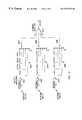
- FIG. 1is a block diagram of one embodiment of the invention
- FIG. 2is a schematic diagram showing one implementation of the combiner used in the embodiment of FIG. 1;
- FIG. 3is a block diagram showing an alternative implementation of the combiner used in the embodiment of FIG. 1;
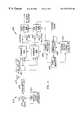
- FIG. 4is a block diagram of an alternative embodiment of the invention.
- FIG. 1shows one embodiment of the invention wherein three antennas 101 , 102 and 103 are attached to the front end of a television receiver 112 .
- These antennasmay be dipoles embedded in the mechanical structure of the television receiver, or external devices such as “rabbit ear” antennas placed in convenient locations and/or orientations in the vicinity of the television receiver.
- Each antennais coupled to two signal combiners 104 and 105 , the output signals of which are selected by multiplexers 106 and 107 as input signals to a respective one of ATSC (Advanced Television Standards Committee) tuner 108 and NTSC (National Television Standards Committee) tuner 109 .
- ATSC tuner 108is required for processing DTV signals
- NTSC tuner 109is used to process conventional analog television signals.
- DTVdigital television
- Most digital television (DTV) receiverswill have one NTSC tuner and one ATSC tuner, since there will be a transition period during which both analog and digital program material will be transmitted.
- DTVdigital television
- only one tuneris in use decoding the program, the tuner being used corresponding to whether the channel being viewed is digital or analog.
- This inventionmakes use of the fact that there are two tuners in the television receiver. It will be understood by those skilled in the art, however, that the two tuners may be of the same type, e.g., both ATSC tuners, if the receiver is designed to receive only one type of transmission, e.g., DTV signals.
- Each of combiners 104 and 105 , multiplexers 106 and 107 and tuners 108 and 109are controlled by a control processor 110 .
- the control processorconfigures combiners 104 and 105 based on evaluations of the output signals of tuners 108 and 109 made by a signal evaluation module 111 .
- multiplexers 106 and 107are controlled to send the output signal of either combiner 104 or combiner 105 to ATSC tuner 108 or, correspondingly, the output signal of either combiner 104 or combiner 105 to NTSC tuner 109 .
- FIG. 2shows an implementation of a combiner unit wherein the signal from each antenna connection thereto passes through a wideband buffer amplifier 201 , 202 and 203 , respectively.
- These wideband amplifiersisolate the incoming signal from the corresponding antenna so that no processing of the signal done by the combiner will be reflected back into the antenna to generate possible interference with the other combiner.
- the antenna signals from buffer amplifiers 201 , 202 and 203are passed through respective tapped delay lines 204 , 205 and 206 .
- Switches 207 , 208 and 209 at the outputs of respective delay lines 204 , 205 and 206select among one of the delayed signals from the antenna, or the ground connection (no signal).
- Switches 207 , 208 and 209are connected to the inputs of a summing amplifier 210 , which provides an output signal to each of the two multiplexers 106 and 107 , shown in FIG. 1 .
- Another method of implementing variable delayis to use a continuously variable delay circuit where the amount of delay is selected by controlling voltage instead of using discrete switched steps. External control of the switches or control voltages allows the output signal of the summing amplifier to be the sum of the antenna signals with independently varied delays.
- FIG. 3shows another implementation of the combiner.
- each antennais connected to the combining unit through a wideband buffer amplifier 301 , 302 and 303 , respectively, which isolates the incoming signal from the corresponding antenna for the same reason as in the FIG. 2 implementation.
- the antennasare coupled to respective variable phase shifters 304 , 305 and 306 which, in turn, are coupled to respective attenuators 307 , 308 and 309 .
- Each of the phase shifters and attenuatorscan be varied continuously with a control voltage, as shown, or in discrete steps with switches.
- External control of the switches or control voltagesallows the output signal of a summing amplifier 310 to be the sum of the antenna signals with independently varied phases. Providing a phase shift of 180° allows summing amplifier 310 to perform a subtraction of signals, resulting in an output signal proportional to the difference between two antenna signals.
- the combiner circuitcan be configured to produce an output signal that is a summation of the different antenna signals with independently determined amounts of delay and phase shift, or with no contribution at all from one or more antennas.
- Spatial diversity combiningis well known in the art for providing enhanced results in many difficult signal reception environments, such as rapidly changing multipath interference environments previously mentioned.
- Traditional methods of achieving enhanced receptioncomprise minimization of mean square error such as described in “Optimum Diversity Combining and Equalization to Digital Data Transmission with Applications to Cellular Mobile Radio—Part I: Theoretical Considerations” by P. Balaban and J. Salz, IEEE Transactions on Communications , Vol. 40, No. 5, pp.
- a television receiver with multiple indoor antennasviewed in a house where movement of persons inside the house, or other environmental changes inside or outside the house, causes the multipath signal environments for all of the TV channels to change with time.
- This television receiveris provided with the circuitry shown in FIG. 1, having two tuners which may be two NTSC tuners, two ATSC tuners, or one NTSC tuner and one ATSC tuner, the latter being typical of DTV receivers capable of receiving both analog and digital programs.
- the channel being observedis received by one of these tuners receiving a signal from either combiner 104 or 105 , depending on the selection by multiplexers 106 and 107 .
- control processor 110uses a signal evaluation module 111 to measure the strength and quality of the signal coming from ATSC tuner 108 (the signal being viewed), and configures multiplexer 107 so that the signal from combiner 105 is sent to NTSC tuner 109 .
- Control processor 110also configures the circuitry of combiner 105 in any one way, for example, with antenna 101 coupled to the summing amplifier ( 210 in FIG. 2 or 310 in FIG. 3) with no delay or phase shift, and no input signal (i.e., switches, 208 and 209 in FIG. 2 set to ground) from antennas 102 and 103 .
- Control processor 110then uses signal evaluation module 111 to measure the strength and quality of the signal produced by the summing amplifier. If this measurement is significantly higher (e.g., 1 dB) than the measurement made from the output of ATSC tuner 108 , multiplexer 106 is reconfigured by control processor 110 so that ATSC tuner 108 now receives the signal from combiner 105 .
- control processor 110configures combiner 105 in a different manner. Processor 110 continues to try different configurations for combiner 105 until a superior signal is found. If and when a superior signal is found, processor 110 causes multiplexer 106 to send the superior signal to ATSC tuner 108 . When this happens, processor 110 changes multiplexer 107 to evaluate the output signal of combiner 104 . Processor 110 configures combiner 104 and evaluates different signal combinations therein in a manner similar to that previously described.
- processor 110can cycle through the various combinations.
- One wayis simply to exhaust all possible discrete settings.
- Another, and generally faster, wayis to vary one parameter at a time to see if it leads to an increase in measured signal strength. If it does, that value of the parameter is adopted as the new setting. If it does not, another parameter is varied. If no single parameter results in an improvement, then two parameters are varied at a time, and so on. This type of sequential refinement is commonly known in the art as “hill climbing”.
- processor 110uses signal evaluation module 111 to re-evaluate the output signal of ATSC tuner 108 to update the quality measurement which may have changed since it was last examined. When this is done, the new value is used for evaluation as described above. Whenever the channel is changed by the viewer, the process begins again.
- AGCautomatic gain control
- the combiner circuitrymay be intelligently driven by a wideband signal overlay correlator.
- a wideband signal overlay correlatoris disclosed in copending application Ser. No. 09/201,376, cited above. This alternative embodiment is illustrated in FIG. 4 .
- the system of FIG. 4comprises a transmitter subsystem 410 and receiver subsystem 420 .
- the transmitter subsystemincludes a first overlay signal generator 411 , an adder 412 and a transmitter 413 .
- a digital television signal to be transmittedis provided to adder 412 .
- Also provided to adder 412is a first overlay signal generated by a first overlay signal generator 411 .
- Adder 412combines the first overlay signal and the digital television signal to provide a combined signal to transmitter 413 for transmission via a transmitting antenna 417 .
- Receiver subsystem 420includes receiving antennas 421 , 422 and 423 , combiners 424 and 425 , multiplexers 426 and 427 , ATSC tuners 428 and 429 , a correlator 430 , second overlay signal generator 431 , phase adjuster 432 , and control processor 433 .
- the first overlay signalis a wide band, relatively low power random signal, having an autocorrelation property that produces periodic correlation peaks but a low cross-correlation property with the digital television signal.
- overlay signal generator 411is a sequence generator which produces an m-sequence as described in Data Transportation and Protection by John E. Hershey and R. K. Rao Yarlagadda, Chapter 8, pp. 273-308, Plenum Press, 1986.
- the combined signal transmitted by transmitter 413is received by antennas 421 , 422 and 423 and supplied to combiners 424 and 425 , in a manner similar to the FIG. 1 embodiment.
- the output signal of one of the combinersis selected by multiplexer 426 and supplied to tuner 428 and the output signal of the other combiner is selected by multiplexer 427 and supplied to tuner 429 , which produces a demodulated signal at an intermediate frequency (IF).
- the IF signalis supplied to correlator 430 and to second overlay signal generator 431 .
- the output signal of correlator 430is supplied to phase adjuster 432 which provides a phase control feedback signal to second overlay signal generator 431 .
- the output signal of phase adjuster 432is also provided to processor 433 which generates control signals for combiners 424 and 425 and multiplexers 426 and 427 .
Landscapes
- Engineering & Computer Science (AREA)
- Signal Processing (AREA)
- Multimedia (AREA)
- Computer Networks & Wireless Communication (AREA)
- Databases & Information Systems (AREA)
- Radio Transmission System (AREA)
Abstract
Description
Claims (14)
Priority Applications (1)
| Application Number | Priority Date | Filing Date | Title |
|---|---|---|---|
| US09/422,445US6577353B1 (en) | 1999-10-21 | 1999-10-21 | Optimization of television reception by selecting among or combining multiple antenna inputs |
Applications Claiming Priority (1)
| Application Number | Priority Date | Filing Date | Title |
|---|---|---|---|
| US09/422,445US6577353B1 (en) | 1999-10-21 | 1999-10-21 | Optimization of television reception by selecting among or combining multiple antenna inputs |
Publications (1)
| Publication Number | Publication Date |
|---|---|
| US6577353B1true US6577353B1 (en) | 2003-06-10 |
Family
ID=23674918
Family Applications (1)
| Application Number | Title | Priority Date | Filing Date |
|---|---|---|---|
| US09/422,445Expired - LifetimeUS6577353B1 (en) | 1999-10-21 | 1999-10-21 | Optimization of television reception by selecting among or combining multiple antenna inputs |
Country Status (1)
| Country | Link |
|---|---|
| US (1) | US6577353B1 (en) |
Cited By (42)
| Publication number | Priority date | Publication date | Assignee | Title |
|---|---|---|---|---|
| US20020033902A1 (en)* | 2000-09-21 | 2002-03-21 | Young-Ho Choi | Tuning system and method in broadcast signal receiver |
| US20020118782A1 (en)* | 2001-02-28 | 2002-08-29 | Pioneer Corporation | Receiver |
| US20020163593A1 (en)* | 2001-03-30 | 2002-11-07 | Tianmin Liu | Method and apparatus for reception of terrestrial digital television signals |
| US20030125003A1 (en)* | 2001-12-28 | 2003-07-03 | Whikehart J. William | Beamsteering control system for a vehicle radio receiver |
| US20040141474A1 (en)* | 2001-04-27 | 2004-07-22 | Chen Ernest C. | Online output multiplexer filter measurement |
| US6784923B1 (en)* | 2000-09-22 | 2004-08-31 | Agere Systems Inc. | Diversity and adaptive antenna arrangements for inductive pick-ups |
| US20040253955A1 (en)* | 2003-06-10 | 2004-12-16 | Love Robert T. | Diversity control in wireless communications devices and methods |
| US20050008100A1 (en)* | 2001-04-27 | 2005-01-13 | Chen Ernest C. | Carrier to noise ratio estimations from a received signal |
| WO2005011266A1 (en)* | 2003-07-28 | 2005-02-03 | Samsung Electronics Co., Ltd. | Method of scanning channel of digital television |
| US20050128362A1 (en)* | 2002-05-31 | 2005-06-16 | Detlef Teichner | Multipath video reception system |
| US20050185097A1 (en)* | 2004-02-20 | 2005-08-25 | Pioneer Corporation | TV receiver and diversity receiving method |
| US20050195335A1 (en)* | 2004-02-13 | 2005-09-08 | Broadcom Corporation | Multi-input multi-output tuner front ends |
| US20060023123A1 (en)* | 2004-07-29 | 2006-02-02 | Kuang-Yu Yen | Digital tv receiver with antenna diversity |
| US20060125708A1 (en)* | 2004-11-29 | 2006-06-15 | Funai Electric Co., Ltd. | Television broadcast receiver |
| US20060143673A1 (en)* | 2004-11-29 | 2006-06-29 | Funai Electric Co., Ltd. | Television broadcast receiver |
| US20060148433A1 (en)* | 2005-01-04 | 2006-07-06 | Welnick William E | Method for controlling diversity receivers in a wireless communication device |
| US20060209217A1 (en)* | 2004-06-02 | 2006-09-21 | Funai Electric Co., Ltd. | Television tuner |
| US20060268113A1 (en)* | 2005-05-29 | 2006-11-30 | Hon Hai Precision Industry Co., Ltd. | Simulation system and method for testing performances of tv tuners |
| US20080055466A1 (en)* | 2006-04-18 | 2008-03-06 | Sanjay Garg | Shared memory multi video channel display apparatus and methods |
| US20080055462A1 (en)* | 2006-04-18 | 2008-03-06 | Sanjay Garg | Shared memory multi video channel display apparatus and methods |
| US20080055470A1 (en)* | 2006-04-18 | 2008-03-06 | Sanjay Garg | Shared memory multi video channel display apparatus and methods |
| US20080316369A1 (en)* | 2005-07-11 | 2008-12-25 | Matsushita Electric Industrial Co., Ltd. | Broadcast Reception Module and Broadcast Device Using the Same |
| US20090031386A1 (en)* | 2007-07-24 | 2009-01-29 | Asustek Computer Inc. | Multi-Antenna Digital Television Box and the Receiving Method Thereof |
| US20090113488A1 (en)* | 2005-08-24 | 2009-04-30 | Thomson Licensing | Dynamic Tuning Between Different Receivers Background |
| US7577213B2 (en) | 2002-07-01 | 2009-08-18 | The Directv Group, Inc. | Hierarchical 8PSK performance |
| US7706466B2 (en) | 2001-04-27 | 2010-04-27 | The Directv Group, Inc. | Lower complexity layered modulation signal processor |
| US7738587B2 (en)* | 2002-07-03 | 2010-06-15 | The Directv Group, Inc. | Method and apparatus for layered modulation |
| US7920643B2 (en) | 2001-04-27 | 2011-04-05 | The Directv Group, Inc. | Maximizing power and spectral efficiencies for layered and conventional modulations |
| US20120108178A1 (en)* | 2009-06-15 | 2012-05-03 | Ming Lee | Antenna system and method for optimizing an rf signal |
| US8208526B2 (en) | 2001-04-27 | 2012-06-26 | The Directv Group, Inc. | Equalizers for layered modulated and other signals |
| US8259641B2 (en) | 2001-04-27 | 2012-09-04 | The Directv Group, Inc. | Feeder link configurations to support layered modulation for digital signals |
| US8660507B1 (en)* | 2012-07-17 | 2014-02-25 | Sprint Spectrum L.P. | Diversity signal reception |
| US8978074B2 (en) | 2011-08-29 | 2015-03-10 | At&T Mobility Ii Llc | Method and apparatus for providing wireless digital television service |
| US20160021368A1 (en)* | 2014-07-16 | 2016-01-21 | Echostar Technologies, Llc | Measurement of ir emissions and adjustment of output signal |
| US9806787B2 (en) | 2014-10-31 | 2017-10-31 | Skyworks Solutions, Inc. | Diversity receiver front end system with flexible antenna routing |
| US20170353688A1 (en)* | 2016-05-11 | 2017-12-07 | Drone Racing League, Inc. | Diversity receiver |
| US20180077450A1 (en)* | 2015-03-17 | 2018-03-15 | Thomson Licensing | Mobile atsc 3.0 receiver as remote antenna |
| US9960482B2 (en) | 2013-03-15 | 2018-05-01 | Agc Automotive Americas R&D, Inc. | Window assembly with transparent regions having a performance enhancing slit formed therein |
| US10034147B2 (en) | 2013-09-26 | 2018-07-24 | Coherent Logix, Incorporated | Next generation broadcast system and method |
| US10341722B2 (en)* | 2016-12-22 | 2019-07-02 | DISH Technologies L.L.C. | Distributed indoor smart antenna system for over-the-air television reception |
| US20200052731A1 (en)* | 2018-08-08 | 2020-02-13 | Avx Antenna, Inc. D/B/A Ethertronics, Inc. | Vhf-uhf antenna system with feedback |
| US11196449B2 (en) | 2018-08-08 | 2021-12-07 | Avx Antenna, Inc. | Methods for configuring a multi-mode antenna system for multi-channel communication systems |
Citations (11)
| Publication number | Priority date | Publication date | Assignee | Title |
|---|---|---|---|---|
| US3681695A (en)* | 1969-09-02 | 1972-08-01 | Raytheon Co | Multipath compensation system |
| US4450585A (en)* | 1981-03-26 | 1984-05-22 | Ferranti Plc | Signal switching and combining systems for diversity radio receiving systems |
| US5159707A (en)* | 1990-04-12 | 1992-10-27 | Pioneer Electronic Corporation | Diversity receiver |
| US5303396A (en)* | 1990-06-13 | 1994-04-12 | Hitachi, Ltd. | Diversity reception having a plurality of antennas for use with moving vehicles |
| US5313660A (en)* | 1991-01-21 | 1994-05-17 | Fuba Hans Kolbe & Co. | Antenna diversity system with at least two antennae for the mobile reception of very-high and ultra-high frequency waves |
| US5335010A (en)* | 1991-02-08 | 1994-08-02 | U.S. Philips Corporation | Antenna diversity receiving system with antenna switching during line periods and signal quality evaluation during line blanking intervals |
| US5818543A (en)* | 1995-09-06 | 1998-10-06 | Premier Wireless, Inc. | Diversity receiver for television |
| US5844632A (en)* | 1994-10-04 | 1998-12-01 | Matsushita Electric Industrial Co., Ltd. | Diversity receiving apparatus for a mobile unit |
| US5848361A (en)* | 1994-10-26 | 1998-12-08 | Northern Telecom Limited | Signal combiner for a radio communication base station arrangement |
| US6188447B1 (en)* | 1996-09-13 | 2001-02-13 | Fuba Automotive Gmbh | Frequency diversity system |
| US6304299B1 (en)* | 1998-11-30 | 2001-10-16 | General Electric Company | System and method for mitigating multipath effects in television systems |
- 1999
- 1999-10-21USUS09/422,445patent/US6577353B1/ennot_activeExpired - Lifetime
Patent Citations (11)
| Publication number | Priority date | Publication date | Assignee | Title |
|---|---|---|---|---|
| US3681695A (en)* | 1969-09-02 | 1972-08-01 | Raytheon Co | Multipath compensation system |
| US4450585A (en)* | 1981-03-26 | 1984-05-22 | Ferranti Plc | Signal switching and combining systems for diversity radio receiving systems |
| US5159707A (en)* | 1990-04-12 | 1992-10-27 | Pioneer Electronic Corporation | Diversity receiver |
| US5303396A (en)* | 1990-06-13 | 1994-04-12 | Hitachi, Ltd. | Diversity reception having a plurality of antennas for use with moving vehicles |
| US5313660A (en)* | 1991-01-21 | 1994-05-17 | Fuba Hans Kolbe & Co. | Antenna diversity system with at least two antennae for the mobile reception of very-high and ultra-high frequency waves |
| US5335010A (en)* | 1991-02-08 | 1994-08-02 | U.S. Philips Corporation | Antenna diversity receiving system with antenna switching during line periods and signal quality evaluation during line blanking intervals |
| US5844632A (en)* | 1994-10-04 | 1998-12-01 | Matsushita Electric Industrial Co., Ltd. | Diversity receiving apparatus for a mobile unit |
| US5848361A (en)* | 1994-10-26 | 1998-12-08 | Northern Telecom Limited | Signal combiner for a radio communication base station arrangement |
| US5818543A (en)* | 1995-09-06 | 1998-10-06 | Premier Wireless, Inc. | Diversity receiver for television |
| US6188447B1 (en)* | 1996-09-13 | 2001-02-13 | Fuba Automotive Gmbh | Frequency diversity system |
| US6304299B1 (en)* | 1998-11-30 | 2001-10-16 | General Electric Company | System and method for mitigating multipath effects in television systems |
Cited By (81)
| Publication number | Priority date | Publication date | Assignee | Title |
|---|---|---|---|---|
| US20020033902A1 (en)* | 2000-09-21 | 2002-03-21 | Young-Ho Choi | Tuning system and method in broadcast signal receiver |
| US6724441B2 (en)* | 2000-09-21 | 2004-04-20 | Samsung Electronics Co., Ltd. | Tuning system and method in broadcast signal receiver |
| US6784923B1 (en)* | 2000-09-22 | 2004-08-31 | Agere Systems Inc. | Diversity and adaptive antenna arrangements for inductive pick-ups |
| US20020118782A1 (en)* | 2001-02-28 | 2002-08-29 | Pioneer Corporation | Receiver |
| US7099415B2 (en)* | 2001-02-28 | 2006-08-29 | Pioneer Corporation | Receiver |
| US20020163593A1 (en)* | 2001-03-30 | 2002-11-07 | Tianmin Liu | Method and apparatus for reception of terrestrial digital television signals |
| US7034893B2 (en)* | 2001-03-30 | 2006-04-25 | Broadcom Corporation | Method and apparatus for reception of terrestrial digital television signals |
| US20040141474A1 (en)* | 2001-04-27 | 2004-07-22 | Chen Ernest C. | Online output multiplexer filter measurement |
| US20050008100A1 (en)* | 2001-04-27 | 2005-01-13 | Chen Ernest C. | Carrier to noise ratio estimations from a received signal |
| US8208526B2 (en) | 2001-04-27 | 2012-06-26 | The Directv Group, Inc. | Equalizers for layered modulated and other signals |
| US8005035B2 (en) | 2001-04-27 | 2011-08-23 | The Directv Group, Inc. | Online output multiplexer filter measurement |
| US7920643B2 (en) | 2001-04-27 | 2011-04-05 | The Directv Group, Inc. | Maximizing power and spectral efficiencies for layered and conventional modulations |
| US8259641B2 (en) | 2001-04-27 | 2012-09-04 | The Directv Group, Inc. | Feeder link configurations to support layered modulation for digital signals |
| US7706466B2 (en) | 2001-04-27 | 2010-04-27 | The Directv Group, Inc. | Lower complexity layered modulation signal processor |
| US7639759B2 (en) | 2001-04-27 | 2009-12-29 | The Directv Group, Inc. | Carrier to noise ratio estimations from a received signal |
| US20030125003A1 (en)* | 2001-12-28 | 2003-07-03 | Whikehart J. William | Beamsteering control system for a vehicle radio receiver |
| US7099644B2 (en)* | 2001-12-28 | 2006-08-29 | Visteon Global Technologies, Inc. | Beamsteering control system for a vehicle radio receiver |
| US20050128362A1 (en)* | 2002-05-31 | 2005-06-16 | Detlef Teichner | Multipath video reception system |
| US7428022B2 (en)* | 2002-05-31 | 2008-09-23 | Harman Becker Automotive Systems Gmbh | Multipath video reception system |
| US7577213B2 (en) | 2002-07-01 | 2009-08-18 | The Directv Group, Inc. | Hierarchical 8PSK performance |
| US7738587B2 (en)* | 2002-07-03 | 2010-06-15 | The Directv Group, Inc. | Method and apparatus for layered modulation |
| US7929921B2 (en) | 2003-06-10 | 2011-04-19 | Motorola Mobility, Inc. | Diversity control in wireless communications devices and methods |
| US20040253955A1 (en)* | 2003-06-10 | 2004-12-16 | Love Robert T. | Diversity control in wireless communications devices and methods |
| US20050054345A1 (en)* | 2003-07-28 | 2005-03-10 | Samsung Electronics Co., Ltd. | Method of scanning channel of digital television |
| US7177640B2 (en) | 2003-07-28 | 2007-02-13 | Samsung Electronics Co., Ltd. | Method of scanning channel of digital television |
| WO2005011266A1 (en)* | 2003-07-28 | 2005-02-03 | Samsung Electronics Co., Ltd. | Method of scanning channel of digital television |
| CN100531327C (en)* | 2003-07-28 | 2009-08-19 | 三星电子株式会社 | Method for scanning channels of digital television |
| US20050195335A1 (en)* | 2004-02-13 | 2005-09-08 | Broadcom Corporation | Multi-input multi-output tuner front ends |
| US7701515B2 (en)* | 2004-02-13 | 2010-04-20 | Broadcom Corporation | Multi-input multi-output tuner front ends |
| US20050185097A1 (en)* | 2004-02-20 | 2005-08-25 | Pioneer Corporation | TV receiver and diversity receiving method |
| US20090180037A1 (en)* | 2004-06-02 | 2009-07-16 | Funai Electric Co., Ltd. | Television tuner |
| US7663704B2 (en)* | 2004-06-02 | 2010-02-16 | Funai Electric Co., Ltd. | Television tuner for control of directivity of antenna |
| US20060209217A1 (en)* | 2004-06-02 | 2006-09-21 | Funai Electric Co., Ltd. | Television tuner |
| US20060023123A1 (en)* | 2004-07-29 | 2006-02-02 | Kuang-Yu Yen | Digital tv receiver with antenna diversity |
| US20060143673A1 (en)* | 2004-11-29 | 2006-06-29 | Funai Electric Co., Ltd. | Television broadcast receiver |
| US20060125708A1 (en)* | 2004-11-29 | 2006-06-15 | Funai Electric Co., Ltd. | Television broadcast receiver |
| US7561213B2 (en)* | 2004-11-29 | 2009-07-14 | Funai Electric Co., Ltd. | Television broadcast receiver |
| US7489913B2 (en)* | 2005-01-04 | 2009-02-10 | Motorola, Inc. | Method for controlling diversity receivers in a wireless communication device |
| US20060148433A1 (en)* | 2005-01-04 | 2006-07-06 | Welnick William E | Method for controlling diversity receivers in a wireless communication device |
| US7639276B2 (en)* | 2005-05-29 | 2009-12-29 | Hong Fu Jin Precision Industry (Shenzhen) Co., Ltd. | Simulation system and method for testing performances of TV tuners |
| US20060268113A1 (en)* | 2005-05-29 | 2006-11-30 | Hon Hai Precision Industry Co., Ltd. | Simulation system and method for testing performances of tv tuners |
| US20080316369A1 (en)* | 2005-07-11 | 2008-12-25 | Matsushita Electric Industrial Co., Ltd. | Broadcast Reception Module and Broadcast Device Using the Same |
| US7952648B2 (en)* | 2005-07-11 | 2011-05-31 | Panasonic Corporation | Broadcast reception module and broadcast device using the same |
| US8055227B2 (en)* | 2005-08-24 | 2011-11-08 | Thomson Licensing | Dynamic tuning between different receivers background |
| US20090113488A1 (en)* | 2005-08-24 | 2009-04-30 | Thomson Licensing | Dynamic Tuning Between Different Receivers Background |
| US8218091B2 (en) | 2006-04-18 | 2012-07-10 | Marvell World Trade Ltd. | Shared memory multi video channel display apparatus and methods |
| US8736757B2 (en) | 2006-04-18 | 2014-05-27 | Marvell World Trade Ltd. | Shared memory multi video channel display apparatus and methods |
| US8804040B2 (en) | 2006-04-18 | 2014-08-12 | Marvell World Trade Ltd. | Shared memory multi video channel display apparatus and methods |
| US20080055470A1 (en)* | 2006-04-18 | 2008-03-06 | Sanjay Garg | Shared memory multi video channel display apparatus and methods |
| US20080055462A1 (en)* | 2006-04-18 | 2008-03-06 | Sanjay Garg | Shared memory multi video channel display apparatus and methods |
| US20080055466A1 (en)* | 2006-04-18 | 2008-03-06 | Sanjay Garg | Shared memory multi video channel display apparatus and methods |
| US8264610B2 (en)* | 2006-04-18 | 2012-09-11 | Marvell World Trade Ltd. | Shared memory multi video channel display apparatus and methods |
| US8284322B2 (en) | 2006-04-18 | 2012-10-09 | Marvell World Trade Ltd. | Shared memory multi video channel display apparatus and methods |
| US8754991B2 (en) | 2006-04-18 | 2014-06-17 | Marvell World Trade Ltd. | Shared memory multi video channel display apparatus and methods |
| US20090031386A1 (en)* | 2007-07-24 | 2009-01-29 | Asustek Computer Inc. | Multi-Antenna Digital Television Box and the Receiving Method Thereof |
| US8948702B2 (en)* | 2009-06-15 | 2015-02-03 | Agc Automotive Americas R&D, Inc. | Antenna system and method for optimizing an RF signal |
| CN102484523A (en)* | 2009-06-15 | 2012-05-30 | Agc汽车美洲研发公司 | Antenna system and method for optimizing an RF signal |
| US9094115B2 (en) | 2009-06-15 | 2015-07-28 | Agc Automotive Americas R&D, Inc. | Antenna system and method for mitigating multi-path effect |
| US20120108178A1 (en)* | 2009-06-15 | 2012-05-03 | Ming Lee | Antenna system and method for optimizing an rf signal |
| US8978074B2 (en) | 2011-08-29 | 2015-03-10 | At&T Mobility Ii Llc | Method and apparatus for providing wireless digital television service |
| US9154850B2 (en) | 2011-08-29 | 2015-10-06 | At&T Mobility Ii Llc | Method and apparatus for providing wireless digital television service |
| US9282380B2 (en) | 2011-08-29 | 2016-03-08 | At&T Mobility Ii Llc | Method and apparatus for providing wireless digital television service |
| US8660507B1 (en)* | 2012-07-17 | 2014-02-25 | Sprint Spectrum L.P. | Diversity signal reception |
| US9960482B2 (en) | 2013-03-15 | 2018-05-01 | Agc Automotive Americas R&D, Inc. | Window assembly with transparent regions having a performance enhancing slit formed therein |
| US10034147B2 (en) | 2013-09-26 | 2018-07-24 | Coherent Logix, Incorporated | Next generation broadcast system and method |
| US20160021368A1 (en)* | 2014-07-16 | 2016-01-21 | Echostar Technologies, Llc | Measurement of ir emissions and adjustment of output signal |
| US10341649B2 (en)* | 2014-07-16 | 2019-07-02 | DISH Technologies L.L.C. | Measurement of IR emissions and adjustment of output signal |
| US9883179B2 (en)* | 2014-07-16 | 2018-01-30 | Echostar Technologies L.L.C. | Measurement of IR emissions and adjustment of output signal |
| US10104371B2 (en)* | 2014-07-16 | 2018-10-16 | DISH Technologies L.L.C. | Measurement of IR emissions and adjustment of output signal |
| US9806787B2 (en) | 2014-10-31 | 2017-10-31 | Skyworks Solutions, Inc. | Diversity receiver front end system with flexible antenna routing |
| US9813137B2 (en) | 2014-10-31 | 2017-11-07 | Skyworks Solutions, Inc. | Diversity receiver front end system with flexible routing |
| US20180077450A1 (en)* | 2015-03-17 | 2018-03-15 | Thomson Licensing | Mobile atsc 3.0 receiver as remote antenna |
| US10715861B2 (en)* | 2015-03-17 | 2020-07-14 | Interdigital Madison Patent Holdings, Sas | Mobile ATSC 3.0 receiver as remote antenna |
| US20170353688A1 (en)* | 2016-05-11 | 2017-12-07 | Drone Racing League, Inc. | Diversity receiver |
| US10499003B2 (en)* | 2016-05-11 | 2019-12-03 | Drone Racing League, Inc. | Diversity receiver |
| US10341722B2 (en)* | 2016-12-22 | 2019-07-02 | DISH Technologies L.L.C. | Distributed indoor smart antenna system for over-the-air television reception |
| US20200052731A1 (en)* | 2018-08-08 | 2020-02-13 | Avx Antenna, Inc. D/B/A Ethertronics, Inc. | Vhf-uhf antenna system with feedback |
| US11063622B2 (en)* | 2018-08-08 | 2021-07-13 | Avx Antenna, Inc. | VHF-UHF antenna system with feedback |
| US11196449B2 (en) | 2018-08-08 | 2021-12-07 | Avx Antenna, Inc. | Methods for configuring a multi-mode antenna system for multi-channel communication systems |
| US11563457B2 (en) | 2018-08-08 | 2023-01-24 | KYOCERA AVX Components (San Diego), Inc. | VHF-UHF antenna system with feedback |
| US11863213B2 (en) | 2018-08-08 | 2024-01-02 | KYOCERA AVX Components (San Diego), Inc. | Methods for configuring a multi-mode antenna system for multi-channel communication systems |
Similar Documents
| Publication | Publication Date | Title |
|---|---|---|
| US6577353B1 (en) | Optimization of television reception by selecting among or combining multiple antenna inputs | |
| US6437832B1 (en) | Mitigation of multipath using ultra wideband DTV overlay signal | |
| US7970366B2 (en) | Diversity receiver | |
| US7034893B2 (en) | Method and apparatus for reception of terrestrial digital television signals | |
| KR100482286B1 (en) | Digital broadcasting service receiver for improving reception ability by switched beamforming | |
| US7072627B2 (en) | Method and apparatus for adjusting signal component strength | |
| US5345599A (en) | Increasing capacity in wireless broadcast systems using distributed transmission/directional reception (DTDR) | |
| CA2136408C (en) | Phased array spread spectrum system and method | |
| GB2313020A (en) | Base Station Apparatus for a CDMA Radio Communication System | |
| KR20030007784A (en) | Diversity combiner for reception of digital television signals | |
| EP1484847A2 (en) | Method and apparatus for controlling a smart antenna using metrics derived from a single carrier digital signal | |
| US20030060218A1 (en) | Automated tuning of wireless peripheral devices | |
| CA2240010C (en) | Co-channel interference canceler in simulcast receiver and method thereof | |
| US6911947B1 (en) | Method and apparatus for reducing multipath distortion in a television signal | |
| US6950477B2 (en) | Blind dual error antenna diversity (DEAD) algorithm for beamforming antenna systems | |
| US20060202890A1 (en) | Adaptive antenna/combiner for reception of satellite signals and associated methods | |
| KR100742172B1 (en) | Method and apparatus for reducing multipath distortion in a television signal | |
| US7702278B2 (en) | Broadcast receiver with smart antenna beam scanning | |
| GB2307375A (en) | Mobile Radio Communication System with Diversity Reception | |
| KR20060093032A (en) | Device for Receiving Digital Signals with Fading Compensation | |
| JP2748829B2 (en) | Satellite broadcast receiver | |
| Meehan | Antenna diversity for improved indoor reception of US Digital terrestrial television receivers | |
| JPS5974708A (en) | Traveling object mounted television receiving antenna device | |
| KR20060111811A (en) | Diversity receiving device and method | |
| KR100831615B1 (en) | Mobile DV Receiver using IF Direct Correlation Based Channel Compensation Circuit |
Legal Events
| Date | Code | Title | Description |
|---|---|---|---|
| AS | Assignment | Owner name:GENERAL ELECTRIC COMPANY, NEW YORK Free format text:ASSIGNMENT OF ASSIGNORS INTEREST;ASSIGNORS:WELLES, KENNETH BRAKELEY II;GRABB, MARK LEWIS;HERSHEY, JOHN ERIK;REEL/FRAME:010335/0342;SIGNING DATES FROM 19991018 TO 19991019 | |
| STCF | Information on status: patent grant | Free format text:PATENTED CASE | |
| FEPP | Fee payment procedure | Free format text:PAYOR NUMBER ASSIGNED (ORIGINAL EVENT CODE: ASPN); ENTITY STATUS OF PATENT OWNER: LARGE ENTITY | |
| FPAY | Fee payment | Year of fee payment:4 | |
| FEPP | Fee payment procedure | Free format text:PAYER NUMBER DE-ASSIGNED (ORIGINAL EVENT CODE: RMPN); ENTITY STATUS OF PATENT OWNER: LARGE ENTITY Free format text:PAYOR NUMBER ASSIGNED (ORIGINAL EVENT CODE: ASPN); ENTITY STATUS OF PATENT OWNER: LARGE ENTITY | |
| FPAY | Fee payment | Year of fee payment:8 | |
| AS | Assignment | Owner name:NBCUNIVERSAL MEDIA, LLC, DELAWARE Free format text:CHANGE OF NAME;ASSIGNORS:GENERAL ELECTRIC COMPANY;NBC UNIVERSAL, INC.;NBC UNIVERSAL MEDIA, LLC;REEL/FRAME:025935/0493 Effective date:20110128 | |
| FPAY | Fee payment | Year of fee payment:12 |