US6577234B1 - Security system - Google Patents
Security systemDownload PDFInfo
- Publication number
- US6577234B1 US6577234B1US09/616,155US61615500AUS6577234B1US 6577234 B1US6577234 B1US 6577234B1US 61615500 AUS61615500 AUS 61615500AUS 6577234 B1US6577234 B1US 6577234B1
- Authority
- US
- United States
- Prior art keywords
- pyramid
- security system
- controller
- unit
- lamp
- Prior art date
- Legal status (The legal status is an assumption and is not a legal conclusion. Google has not performed a legal analysis and makes no representation as to the accuracy of the status listed.)
- Expired - Fee Related
Links
- 238000004891communicationMethods0.000claimsabstractdescription30
- 230000004044responseEffects0.000claimsabstractdescription22
- 238000003032molecular dockingMethods0.000claimsdescription8
- 238000005286illuminationMethods0.000claimsdescription5
- 230000007246mechanismEffects0.000claimsdescription3
- 230000008867communication pathwayEffects0.000description16
- 238000012545processingMethods0.000description10
- 238000012544monitoring processMethods0.000description9
- 230000008878couplingEffects0.000description7
- 238000010168coupling processMethods0.000description7
- 238000005859coupling reactionMethods0.000description7
- UGFAIRIUMAVXCW-UHFFFAOYSA-NCarbon monoxideChemical compound[O+]#[C-]UGFAIRIUMAVXCW-UHFFFAOYSA-N0.000description5
- 229910002091carbon monoxideInorganic materials0.000description5
- 230000001902propagating effectEffects0.000description5
- 230000004913activationEffects0.000description4
- 230000006870functionEffects0.000description3
- 239000004973liquid crystal related substanceSubstances0.000description3
- 238000012986modificationMethods0.000description3
- 230000004048modificationEffects0.000description3
- 238000012546transferMethods0.000description3
- XLYOFNOQVPJJNP-UHFFFAOYSA-NwaterSubstancesOXLYOFNOQVPJJNP-UHFFFAOYSA-N0.000description3
- 210000004247handAnatomy0.000description2
- 239000000463materialSubstances0.000description2
- 238000000034methodMethods0.000description2
- 230000037361pathwayEffects0.000description2
- 229910052704radonInorganic materials0.000description2
- SYUHGPGVQRZVTB-UHFFFAOYSA-Nradon atomChemical compound[Rn]SYUHGPGVQRZVTB-UHFFFAOYSA-N0.000description2
- 230000000007visual effectEffects0.000description2
- 230000003213activating effectEffects0.000description1
- 238000013459approachMethods0.000description1
- 230000009118appropriate responseEffects0.000description1
- OJIJEKBXJYRIBZ-UHFFFAOYSA-Ncadmium nickelChemical compound[Ni].[Cd]OJIJEKBXJYRIBZ-UHFFFAOYSA-N0.000description1
- 239000003086colorantSubstances0.000description1
- 239000002131composite materialSubstances0.000description1
- 238000013479data entryMethods0.000description1
- 238000001514detection methodMethods0.000description1
- 238000005516engineering processMethods0.000description1
- 239000011152fibreglassSubstances0.000description1
- -1for instanceSubstances0.000description1
- 239000011521glassSubstances0.000description1
- 229910052736halogenInorganic materials0.000description1
- 150000002367halogensChemical class0.000description1
- 230000003116impacting effectEffects0.000description1
- 230000000977initiatory effectEffects0.000description1
- 238000009434installationMethods0.000description1
- 230000010354integrationEffects0.000description1
- 230000003993interactionEffects0.000description1
- 230000001788irregularEffects0.000description1
- 229910052751metalInorganic materials0.000description1
- 239000002184metalSubstances0.000description1
- 239000004033plasticSubstances0.000description1
- 230000035755proliferationEffects0.000description1
- 230000004224protectionEffects0.000description1
- 230000003252repetitive effectEffects0.000description1
- 238000005096rolling processMethods0.000description1
- 230000019491signal transductionEffects0.000description1
- 210000003462veinAnatomy0.000description1
- 210000000707wristAnatomy0.000description1
Images


Classifications
- G—PHYSICS
- G08—SIGNALLING
- G08B—SIGNALLING OR CALLING SYSTEMS; ORDER TELEGRAPHS; ALARM SYSTEMS
- G08B13/00—Burglar, theft or intruder alarms
- G—PHYSICS
- G08—SIGNALLING
- G08B—SIGNALLING OR CALLING SYSTEMS; ORDER TELEGRAPHS; ALARM SYSTEMS
- G08B13/00—Burglar, theft or intruder alarms
- G08B13/18—Actuation by interference with heat, light, or radiation of shorter wavelength; Actuation by intruding sources of heat, light, or radiation of shorter wavelength
- G08B13/189—Actuation by interference with heat, light, or radiation of shorter wavelength; Actuation by intruding sources of heat, light, or radiation of shorter wavelength using passive radiation detection systems
- G08B13/19—Actuation by interference with heat, light, or radiation of shorter wavelength; Actuation by intruding sources of heat, light, or radiation of shorter wavelength using passive radiation detection systems using infrared-radiation detection systems
- G—PHYSICS
- G08—SIGNALLING
- G08B—SIGNALLING OR CALLING SYSTEMS; ORDER TELEGRAPHS; ALARM SYSTEMS
- G08B25/00—Alarm systems in which the location of the alarm condition is signalled to a central station, e.g. fire or police telegraphic systems
- G08B25/01—Alarm systems in which the location of the alarm condition is signalled to a central station, e.g. fire or police telegraphic systems characterised by the transmission medium
- G08B25/10—Alarm systems in which the location of the alarm condition is signalled to a central station, e.g. fire or police telegraphic systems characterised by the transmission medium using wireless transmission systems
Definitions
- This inventionrelates to methods and apparatus for providing security in homes, apartments, hotel rooms and other dwelling spaces and business establishments.
- a new and improved security systemcomprising a main unit having programmable apparatus movable between an active or “ARMED” mode for emitting an alerting stimulus in response to the presence of danger, an inactive or “DISARMED” mode, a “BYPASS” mode and a “TROUBLED” mode indicating irregular operation.
- An indicatorindicates whether the apparatus is in the “ARMED”, “DISARMED” and “TROUBLED” mode.
- the alerting stimuluscomprises one or more of a visual stimulus provided from a lamp and/or a segmented display, an audible stimulus provided from a horn or speaker, and the activation of a signal apparatus for alerting emergency and/or monitoring personnel over a communication pathway.
- the apparatusincludes a detector for detecting danger whether posed from an intruder, fire, gas or carbon monoxide buildup, or other form of danger.
- the systemmay further include one or more satellite units coupled in signal communication with the main unit. Each satellite unit include similar structure to that of the main unit, and in response to sensing danger, sends a signal to the main unit which causes the main unit to emit one or more of the alerting stimuli.
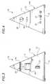
- FIG. 1is a perspective view of a security system
- FIG. 2is another perspective view of the security system of FIG. 1;
- FIG. 3is a front elevational view of the security system of FIG. 1;
- FIG. 4is a rear elevational view of the security system of FIG. 1;
- FIG. 5is a top plan view of the security system of FIG. 1;
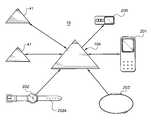
- FIG. 6is a schematic representation of the security system of FIG. 1 and a satellite element
- FIG. 7is a schematic representation of the security system of FIG. 1 and a plurality of satellite elements
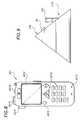
- FIG. 8is a general representation of a satellite unit of the invention.
- FIG. 9is a view showing the satellite unit of FIG. 8 as it would appear situated in a docking station of the security system of FIG. 1 .
- the present inventionis comprised of a personalized security system and of associated methods for providing personalized security.
- the inventionis easy to use, portable and can be adapted as a network of nodes or stations that operate together in harmony for facilitating security service in and out of the home and even at the same time.
- the networkis programmable and user friendly, and the nodes incorporate data structures or systems for facilitating communication therebetween and with one or more central or remote monitoring stations.
- the inventioncontemplates the integration of pagers, wireless telephones, hand-held and portable computing devices and other devices capable sending and receiving data over one or more communication pathways.
- the inventionmay also be incorporated with a networked computer environment, such as a local area network (LAN) or the Internet.
- LANlocal area network
- the Internetsuch as a local area network (LAN) or the Internet.
- FIGS. 1 and 2illustrate perspective views of a security system 10 for detecting danger and for emitting an alerting stimulus in response to the presence of danger.
- system 10is capable of detecting the danger.
- System 10is discrete, self-contained and is portable and well suited for use in structures such as houses, apartments, businesses, boats, trailers, motor- and mobile-homes and other structures lacking dedicated security systems, and by frequent travelers.
- the term “danger” as used in this disclosureis intended to comprise any event and/or individual(s) that pose a threat to property and/or personal safety such as a criminal, a burglar, a thief or an unwanted intruder, fire, unsafe or unwanted levels of gas or carbon monoxide, water, etc.
- System 10is comprised of a main, mother or central unit 10 A having apparatus 20 (FIG. 1) for detecting danger and for emitting an alerting stimulus in response thereto.
- Apparatus 20is contained substantially by a housing 11 .
- housing 11is the shape of a substantial pyramid, having a polygonal base 12 and triangular faces 13 that meet at a common point 14 .
- Housing 11is constructed of any substantially rigid material or materials such as, for instance, fiberglass, strong plastic, a metal or metallic composite material, etc. The pyramid shape makes housing 11 very strong and substantially unbreakable by intruders.
- Unit 10 Anormally rests with base 12 against surface and common point 14 projects upwardly.
- Apparatus 20is comprised of a variety of components including a controller 21 , a detector 22 , a segmented display 23 , a switch 24 for turning apparatus 20 “ON” and “OFF” and for doing other things as will be explained, a display 25 and a monitor 101 and an associated input device or apparatus or controls 102 , a panic switch 26 , a horn or speaker 27 , a receiver/transmitter 28 , a lamp 29 , a camera 100 (shown only in FIG. 1 ), a discrete power source 30 and a power cord 31 engagable to a fixed power source 32 such as a wall transformer.
- a controller 21a controller 21 , a detector 22 , a segmented display 23 , a switch 24 for turning apparatus 20 “ON” and “OFF” and for doing other things as will be explained, a display 25 and a monitor 101 and an associated input device or apparatus or controls 102 , a panic switch 26 , a horn or speaker 27 , a receiver
- Display 25is functional for displaying the operational data and parameters of system 10 and one or more menus and for displaying images.
- Input apparatus 102may comprise a keypad, a pointer, a display that is responsive to direct physical stimulus, a voice response system, etc.
- Lamp 29is located at and defines the common point 14 of housing 11 and it may be positioned at other locations.
- Controller 21is programmable and contains a micro-controller or processing apparatus 21 A that is run by software.
- Processing apparatus 21 Acontrols the operation of apparatus 20 , the interaction between the various components of apparatus 20 , and a processing infrastructure that is adapted, configured, and arranged for facilitating communications capabilities, with a data propagating structure for causing a data transfer with associated satellite units and with a searching and locating data structure.
- the data propagating structure, satellite units and the searching and locating data structurewill be discussed later in this specification.
- Electrical powermay be provided to controller 21 from the fixed power source 32 via power cord 31 , and from discrete power source 30 .
- Discrete power source 30is a rechargeable nickel-cadmium battery or other form of discrete, rechargeable power source or non-rechargeable power source.
- Controller 21is coupled electrically to discrete power source 30 , power cord 31 and to components 22 - 29 in a conventional manner.
- Power cord 31is also coupled electrically to discrete power source 30 , and provides discrete power source 30 with charging electrical energy when plugged into fixed power source 32 .
- Electrical poweris channeled to the various components of apparatus 20 through controller 21 and this is not essential.
- detector 22is supported by housing 11 and is substantially exposed through one of faces 13 , which allows it to sense danger such as in the form of motion from an intruder, heat from fire, noise from broken glass and other sounds, and/or gas, carbon monoxide, radon, moisture, water, etc.
- detector 22may comprise a motion detector such as a passive infrared motion detector, a heat detector, a noise detector, a radon detector, a moisture or water detector, a gas or carbon monoxide detector and any combination thereof among potential others.
- Unit 10 Amay be equipped with a universal detector or sensor port 15 (FIG.
- segmented display 23is comprised of a plurality of lights 33 arranged in substantially linear series. Lights 33 are supported by housing 11 and are exposed through a groove or opening 34 (FIG. 5) formed in three faces 13 of housing 11 and they may be exposed through less or more.
- Display 25 and switch 24are also supported by housing 11 and are each exposed (FIGS. 3 and 4, respectively). Switch 24 is conveniently located and may be engaged and actuated for moving apparatus 20 into an “ARMED” condition or mode, an inactive or “DISARMED” condition or mode, a “BYPASS” condition or mode, an “AWAKE” condition or mode and a “SLEEP” condition or mode.
- ARMEDapparatus 20 is active for sensing danger and for emitting an alerting stimulus in response thereto.
- DISARMEDapparatus 20 is inactive.
- the “ARMED” condition of apparatus 20is disabled, but it does not render apparatus 20 inactive, but only prevents apparatus 20 from emitting an alerting stimulus in response to sensing or detecting danger, which it still does in the “BYPASS” mode.
- the “BYPASS” modeis convenient, because it allows an individual to be in the same room as unit 10 A without it emitting an alerting stimulus.
- the userWhen the user leaves the room or wishes to place apparatus 20 into the “ARMED” condition, the user need only actuate switch 24 to move apparatus 20 from the “BYPASS” mode to the “ARMED” mode.
- the usermay simply engage and actuate panic switch 26 , which will automatically cause apparatus 20 to emit the programmed alerting stimulus.
- apparatus 20is adapted and arranged to emit the programmed alerting stimulus in each of the “ARMED”, “DISARMED” and “BYPASS” modes.
- the “SLEEP” conditionis the low power mode, which provides a very low amount of power to the electrical components of unit 10 A.
- the “SLEEP” modeis used primarily for shipping. From the “AWAKE” mode, which is a mode that places unit 10 A into a standby state, unit 10 A may be moved into any other operational mode.
- Display 25is an illuminated display such as a display having a substantial flat form factor, a liquid crystal display, an LED display or other suitable illuminated display, and displays information such as whether apparatus 20 is in the “ARMED” condition by displaying “A”, the “DISARMED” condition by displaying “D”, the “BYPASS” condition by displaying “B”, the “SLEEP” mode by displaying an “S”, and the “AWAKE” mode by displaying “AK”.
- controller 21is always energized and actuates display 25 for showing the “A” or the “D” or the “S” regardless of whether power cord 31 is plugged into a fixed power source.
- Display 25is optional, and a light, such as LED 16 FIG. 1, may be provide to illuminate in different colors or in different illuminated state for indicating the various modes of operation ad described herein in lieu of display 25 .
- Unit 10 Ahas a relatively small, compact countenance and may be situated anywhere in a room a user desires. After plugging power cord 31 into a fixed power source, such as fixed power source 32 , the user may move or actuate switch 24 to turn unit 10 A “ON” and place apparatus 20 into the “ARMED” condition. Normally, system 10 is activated when the owner or occupant is leaving the given premises or, perhaps, going to bed. Upon arming apparatus 20 , horn 27 will chirp a given number of times, such as seven or more or less times, and segmented display 23 will flash and display 25 will show the “D”. This defines an “Exit Delay” mode of apparatus 20 , during which time a user is given time to leave the premises prior to system 10 arming itself.
- apparatus 20After a predetermined period of time has elapsed, such as ten to fifteen seconds, apparatus 20 will move out of the “Exit Delay” mode and into the “ARMED” mode, at which time horn 27 chirps a given number of times, such as two or more or less times, display 25 displays the “A” and segmented display 23 ceases its flashing.
- apparatus 20is sensitive to danger, whether one or many, and emits an alerting stimulus when it detects danger.
- Controller 21initiates the alerting stimulus in response to the detection of danger by detector 22 .
- the alerting stimulusmay comprise an illumination of lamp 29 , an activation of horn 27 to emit a loud audible stimulus or alarm, an illumination of segmented display 23 and/or an activation of a communications apparatus 35 for alerting emergency or monitoring personnel over a communication pathway and/or for activating another component or components of system 10 as will be discussed later in this specification.
- the communication pathwaycan comprise any of a potentially vast array of wired and/or wireless telephony or communication pathways including modem, a cable communication pathway, a communication pathway facilitated over a local or central computer network, such as a local area network (LAN) or the Internet, a radio frequency communication pathway, a cable television communication pathway and any combination thereof among potentially many others.
- LANlocal area network
- the Internetcommunication may be facilitated through a portal, i.e., a publicly accessible web site, using an encrypted or non-encrypted communications protocol.
- Controller 21may be programmed for emitting any one or more or each of the alerting stimulus.
- Communications apparatus 35is considered part of apparatus 20 , and comprises a programmable communication device 35 A that upon activation, establishes a communications link with a central monitoring station over one or more communication pathways.
- the central monitoring stationreceives the call, it alerts personnel stationed at the central monitoring station to a potential emergency situation and the location from which the call is being placed.
- the monitoring personnelcan then either dispatch fire, police and/or paramedic emergency personnel or alert the fire, police and/or paramedic emergency personnel to the emergency situation.
- Camera 100(FIG. 1) is an important feature of the invention, as it may be actuated from a remote location via one or more signal or communication pathways facilitated by communications apparatus 35 .
- emergency personnelWhen emergency personnel are alerted to a potential emergency situation by system 10 , they may control, actuate and use camera 100 for seeing into the dwelling structure for visually identifying the state of the alert.
- the central monitoring stationis equipped with a monitor is display devices for allowing the emergency or monitoring personnel to view images taken by camera 100 . With this capability, the emergency personnel are given the ability to dispatch or alert the appropriate response team.
- Camera 100may be a digital or analog video camera or a still photograph camera, and is preferably equipped with a wide-angle lens for facilitating a wide field of view, and a plurality of cameras may be employed.
- Camera 100is shown supported by and extending through housing 11 , and it may be a separate, discrete, and/or remote component if desired.
- One or more of the other satellite components of the inventionmay also be equipped or provided with a camera and all of the other structural components of unit 10 A as may be desired.
- each or any of the satellite units, including main unit 10 Amay be equipped with a monitor or display and associated controls, like monitor 101 and controls 102 of unit 10 A.
- Monitor 102like all monitors of this disclosure, comprises an illuminated display such as a display having a substantial flat form factor, a liquid crystal display, an LED display or other suitable illuminated display.
- Port 37is carried by housing 11 , and is adapted and arranged as a gateway for establishing or facilitating communications links, sending and receiving communication signals, and for sending and receiving communication signals over any one or more of the communication pathways disclosed and previously defined in this specification.
- Port 37is interfaced with camera 100 , apparatus 20 and the associated display and/or monitor, and each or one or more of the other satellite units of system 10 may also be provided with a similar port.
- port 37is further adapted and arranged to provide a wireless coupling to one or more communication pathways and/or to provide a direct physical coupling to a communication cable or line, such as a phone or modem line 38 as substantially shown in FIG. 6 .
- controller 21may be programmed to activate segmented display 23 into one of a plurality of different illuminated conditions, each illuminated condition for indicating one of the “ARMED”, “DISARMED” and “BYPASS” conditions.
- the illuminated conditionsmay comprise a strobing condition, a rolling condition, a steady condition, etc.
- apparatus 20may also be moved into a “TROUBLED” condition. During normal use, system 10 should always be coupled to a fixed power source.
- controller 21may be programmed to actuate horn 27 for emitting a loud audible siren or stimulus and/or segmented display 23 to indicate one or both of these events, each of which comprises a “TROUBLED CONDITION”. Plugging power cord 31 into a fixed power source, replacing discrete power source 30 or recharging discrete power source 30 above the predetermined threshold each solve the “TROUBLED CONDITION”. Once the troubled condition is remedied, controller 21 deactivates horn 27 and/or segmented display 23 .
- switch 24is also for turning lamp 29 “ON” and “OFF” and this may be done with another switch if desired.
- lamp 29illuminates. In this illuminated state, unit 10 A may be held and used as a flashlight.
- controller 21may be programmed to actuate and illuminate lamp 29 . Power fail circuitry 40 of controller 21 provides this function.
- system 10can be immediately and easily unplugged to be used as an emergency flashlight to illuminate safe exits.
- controller 21Upon re-engaging power cord 31 to fixed power source 32 , controller 21 is normally programmed to deactivate lamp 29 .
- Lamp 29is contained in a transparent housing which defines that portion of housing 11 leading to common point 14 , and is preferably comprised of a halogen light bulb or other high intensity fixture suitable for providing a bright illumination.
- receiver/transmitter 28facilitates communication links with the other satellite units over any one or more of the communications pathways as defined herein, including, for instance, broadband or radio frequency signal communications links.
- system 10further includes a satellite unit 41 and more can be provided as previously intimated, but only one is shown now for the purpose of illustration. Satellite unit 41 is for placement at a location away or remote from unit 10 A, such as in another room of a dwelling structure, and includes substantially the same structural components as unit 10 A, details of which will not be again discussed as it would be unnecessarily repetitive.
- Unit 41includes a receiver/transmitter 42 for facilitating a communication and/or data link with unit 10 A over any one or more of the communication pathways previously discussed and defined in this specification and with other satellite units.
- Receiver/transmitter 42is adapted and arranged to be coupled to receiver/transmitter 28 in signal and data communication.
- controller 21In the event satellite unit 41 detects danger, its controller sends a signal from receiver/transmitter 42 to receiver/transmitter 28 of unit 10 A. In response to receiving this signal, controller 21 initiates the alerting stimulus.
- One or more satellites units, including unit 41may be coupled to unit 10 A in data and signal communication over a wireless or wired communication pathway.
- a potentially vast number of satellite unitsmay be incorporated into system 10 , and they may take on many forms or incorporated into a potentially vast number of electronic devices that many people use on a daily basis such as pagers, desk-top or lap-top computers, cell- or wireless telephones or individual subscriber units (ISUs) of a wireless communication network, portable or hand-held computers and other devices capable of accessing the Internet, wrist and pocket watches, etc.
- ISUsindividual subscriber units
- FIG. 7illustrates system 10 including unit 10 A, two satellite units 41 and more may be provided, and satellite units incorporated as or into or with a pager 200 , a wireless telephone 201 , a watch 202 and a collar 203 among potentially many other devices.
- Collar 203may be fitted onto a child or pet, and may be equipped with a proximity detector that is designed to cause unit 10 A to emit an alerting stimulus when it passes beyond a predetermined or preprogrammed range.
- Watch 202is carried by a strap 202 A, and strap 202 A and collar 203 have engagement structure or couplings, like clip or buckle structure, engagable in a wrapped or coupled condition for engagement to a person or animal in an encircling condition.
- Collar 203 and strap 202 Aare preferably equipped with electronic couplings operative for causing a signal to be sent to unit 10 A to cause unit 10 A to emit an alerting stimulus when either one of their couplings become disengaged.
- the alerting stimulusbecomes manifest, it is envisioned that the charges of the child or pet will become alerted to a possible problem.
- system 10will include unit 10 A and one or more satellite units such as units 41 , one or more pagers 200 , one or more phones 201 , etc.
- the various elements of system 10are coded with a signature data structure so that the various elements are essentially aware of the existence of the other components, or that at least unit 10 A is essentially aware of the other satellite units.
- unit 10 Ais “ON”, the searching and locating data structure of processing apparatus 21 A initializes and initiates a signature search for any active satellites.
- activemeans only that the unit is “ON” or energized.
- the controller of each of the satellitesWhen turned “ON”, the controller of each of the satellites are configured and arranged to emit a signature signal, which processing apparatus 21 A of unit 10 A is capable of searching for and locating or detecting over any one of the communication pathways previously defined in this specification.
- processing apparatus 21 A of unit 10 AWhen unit 10 A has located the satellite units, it then knows that they are there and part of system 10 .
- data-propagating structure of processing apparatus 21 A of unit 10 Auploads its operating data platform to the other active satellites, which the satellites store into their memory. This ensures that the operational parameters between unit 10 A and its associated satellites are consistent. All programming and data entry normally takes place at unit 10 A, which programming and data propagates throughout the satellite units by way of the data propagating structure of processing apparatus 21 A of unit 10 A.
- the processing and control apparatus of unit 10 A and all of the satellite unitsinclude memory.
- the data propagating structure of processing apparatus 21 A of unit 10 Amay be programmed for periodically or continuously updating the programming and data with the satellites.
- each satelliteis substantially similar in structure and function to unit 10 A, with the exception of the shape of housing 11 in some instances, each satellite unit is equipped with an input device and associated display and a processing infrastructure that is adapted, configured, and arranged for facilitating communications capabilities, a data-propagating structure for causing a data transfer with associated satellite units and a searching and locating data structure.
- a usermay select any one of the other satellite units to function as the main unit.
- a usermay call into and access controller 21 via communications apparatus 35 of unit 10 A over a wired and/or wireless telecommunications link and enter programming commands into controller 21 of unit 10 A.
- system 10may be equipped with a voice-interactive telephony system for allowing a user to enter programming commands by voice response.
- any one of the satellite unitscan be equipped with a monitor and with the ability to actuate camera 100 for displaying images taken by camera 100 .
- FIG. 8is an enlarged view of phone 201 (ISU) of FIG. 7 .
- ISUphone 201
- phone 201is shown equipped with a camera 201 A, a detector 201 B, a display/monitor 201 C and an associated input device 201 D, which in this embodiment is a keypad, a panic switch 201 E a light 201 F having a high intensity light bulb and which is useful as a flashlight as previously disclosed, and a universal detector or sensor port 201 G.
- FIG. 9illustrates phone 201 of FIG. 7 as it would appear situated into a docking station 210 formed into and through housing 11 of unit 10 A.
- Docking station 210is equipped with couplings for providing recharging electrical energy to the battery of phone 201 and for facilitating a data transfer between phone 210 and unit 10 A as provided by the data propagating structure discussed previously in this specification.
- Docking station 210includes a locking mechanism for locking phone 201 in place, such that it can only be removed by a key, combination, etc.
- phone 201(FIG.
- one of the keys of input device 201 Dmay be configured as a “LOCATOR” button or key that when pressed brings up a menu on display 201 C.
- a usermay interact with a menu for communicating with unit 10 A and letting unit 10 A know where phone 201 is located.
- the usercan, for instance, enter the state, city and address at which he is located, whether he is at an apartment, a hotel and even the hotel room or apartment number, a house, a boat, a bus, etc.
- phone 201may be configured to request the user to input a security code prior to allowing the user access to the manual locator feature of the invention.
- the security codemay comprise a numbered and/or lettered code or perhaps a voice response password.
- any of the satellite units of the inventionmay be configured with a signal strength indicator including an associated display for showing the signal strength with some sort of sensible indicia or the like.
- the displaymay comprise an LED or liquid crystal display or other suitable display.
- the parent or charge of the childcan use another satellite unit and even the main unit and then move it in various directions until the signal strength is strongest, which would indicate the general direction of the child's satellite unit. This, of course, would give the parent or charge of the child a sense of where the child is located so that he or she may be easily found.
Landscapes
- Physics & Mathematics (AREA)
- General Physics & Mathematics (AREA)
- Engineering & Computer Science (AREA)
- Computer Networks & Wireless Communication (AREA)
- Business, Economics & Management (AREA)
- Emergency Management (AREA)
- Alarm Systems (AREA)
- Lenses (AREA)
Abstract
Description
Claims (12)
Priority Applications (5)
| Application Number | Priority Date | Filing Date | Title |
|---|---|---|---|
| US09/616,155US6577234B1 (en) | 1999-11-02 | 2000-07-14 | Security system |
| EP00309677AEP1143392A3 (en) | 1999-11-02 | 2000-11-01 | Security sytem |
| CA002324852ACA2324852A1 (en) | 1999-11-02 | 2000-11-01 | Security system |
| AU2002222967AAU2002222967A1 (en) | 2000-07-14 | 2001-07-13 | Security system |
| PCT/US2001/022161WO2002007121A1 (en) | 2000-07-14 | 2001-07-13 | Security system |
Applications Claiming Priority (2)
| Application Number | Priority Date | Filing Date | Title |
|---|---|---|---|
| US09/432,669US6288642B1 (en) | 1999-11-02 | 1999-11-02 | Self-contained security system |
| US09/616,155US6577234B1 (en) | 1999-11-02 | 2000-07-14 | Security system |
Related Parent Applications (1)
| Application Number | Title | Priority Date | Filing Date |
|---|---|---|---|
| US09/432,669Continuation-In-PartUS6288642B1 (en) | 1999-11-02 | 1999-11-02 | Self-contained security system |
Publications (1)
| Publication Number | Publication Date |
|---|---|
| US6577234B1true US6577234B1 (en) | 2003-06-10 |
Family
ID=27029593
Family Applications (1)
| Application Number | Title | Priority Date | Filing Date |
|---|---|---|---|
| US09/616,155Expired - Fee RelatedUS6577234B1 (en) | 1999-11-02 | 2000-07-14 | Security system |
Country Status (3)
| Country | Link |
|---|---|
| US (1) | US6577234B1 (en) |
| EP (1) | EP1143392A3 (en) |
| CA (1) | CA2324852A1 (en) |
Cited By (40)
| Publication number | Priority date | Publication date | Assignee | Title |
|---|---|---|---|---|
| US20030137422A1 (en)* | 2002-01-21 | 2003-07-24 | Nec Corporation | Portable telephone set with crime prevention function |
| US20040135685A1 (en)* | 2002-09-23 | 2004-07-15 | John Hane | Security system and method |
| US20040212678A1 (en)* | 2003-04-25 | 2004-10-28 | Cooper Peter David | Low power motion detection system |
| US7019671B2 (en)* | 2002-12-18 | 2006-03-28 | Canon Kabushiki Kaisha | Image-taking apparatus and monitoring system |
| US20060109103A1 (en)* | 2004-11-11 | 2006-05-25 | Robert Bradus | Transmission technique for a portable alarm system |
| US20060203101A1 (en)* | 2005-03-14 | 2006-09-14 | Silsby Christopher D | Motion detecting camera system |
| US20060239250A1 (en)* | 2002-06-20 | 2006-10-26 | Elliot Harvey A | Two-way voice and voice over IP receivers for alarm systems |
| US20070024443A1 (en)* | 2005-07-29 | 2007-02-01 | Honeywell International Inc | Glassbreak alarm recorder for false alarm verification |
| US20070035415A1 (en)* | 2005-08-11 | 2007-02-15 | Dawson N R | System and method for programming a code of an emergency call transmitter |
| US20070085674A1 (en)* | 2005-10-14 | 2007-04-19 | Sharpe Jon B | Self-contained cellular security system |
| US20070222624A1 (en)* | 2006-03-22 | 2007-09-27 | Radio Systems Corporation | Pet alert collar |
| US20070232288A1 (en)* | 2006-03-30 | 2007-10-04 | Mcfarland Norman R | Service tool for wireless automation systems |
| WO2008019339A3 (en)* | 2006-08-04 | 2008-04-24 | Micah Paul Anderson | Security system and method using mobile-telephone technology |
| US20080117029A1 (en)* | 2005-01-25 | 2008-05-22 | Lasershield Systems, Inc. | System and method for reliable communications in a one-way communication system |
| US20080118039A1 (en)* | 2002-06-20 | 2008-05-22 | Elliot Harvey A | Enhanced 911 notification for internet enabled alarm system |
| US20080180935A1 (en)* | 2007-01-25 | 2008-07-31 | Mark Burdeen | RFID emergency lighting system |
| US7437148B1 (en)* | 2001-06-08 | 2008-10-14 | Vaghi Family Intellectual Properties, Llc | Personal communications system and method |
| US20090098865A1 (en)* | 2001-06-08 | 2009-04-16 | Vaghi Nino R | Personal communications system and method |
| US20100205534A1 (en)* | 2000-06-02 | 2010-08-12 | At&T Intellectual Property I, L.P. F/K/A Bellsouth Intellectual Property Corporation | Method Of Facilitating Access To IP-Based Emergency Services |
| US20100283607A1 (en)* | 2007-11-14 | 2010-11-11 | Honeywell International, Inc. | Glass-break shock sensor with validation |
| US20110169628A1 (en)* | 2002-06-20 | 2011-07-14 | Harvey Alexander Elliot | Wireless voip network for security system monitoring |
| US20110234396A1 (en)* | 2010-03-24 | 2011-09-29 | Safeawake, Llc | Fire and emergency warning and locator system |
| US20120319840A1 (en)* | 2011-06-15 | 2012-12-20 | David Amis | Systems and methods to activate a security protocol using an object with embedded safety technology |
| ITBO20110685A1 (en)* | 2011-12-01 | 2013-06-02 | Veronica Righini | THEFT PROTECTION |
| US20130270906A1 (en)* | 2012-04-12 | 2013-10-17 | Ching-Nan Yang | Uninterruptible illumination system |
| US8705704B2 (en) | 2011-04-04 | 2014-04-22 | Numerex Corp. | Delivery of alarm system event data and audio over hybrid networks |
| US8705716B2 (en) | 2011-04-27 | 2014-04-22 | Numerex Corp. | Interactive control of alarm systems by telephone interface using an intermediate gateway |
| US8798260B2 (en) | 2011-04-04 | 2014-08-05 | Numerex Corp. | Delivery of alarm system event data and audio |
| US9054893B2 (en) | 2002-06-20 | 2015-06-09 | Numerex Corp. | Alarm system IP network with PSTN output |
| US9131040B2 (en) | 2002-06-20 | 2015-09-08 | Numerex Corp. | Alarm system for use over satellite broadband |
| US9177464B2 (en) | 2012-09-28 | 2015-11-03 | Numerex Corp. | Method and system for untethered two-way voice communication for an alarm system |
| US9183730B1 (en) | 2014-07-16 | 2015-11-10 | Numerex Corp. | Method and system for mitigating invasion risk associated with stranger interactions in a security system environment |
| US9263910B2 (en)* | 2014-02-06 | 2016-02-16 | Lenovo (Singapore) Pte. Ltd. | Wireless charging system for multi-mode device |
| US9449497B2 (en) | 2014-10-24 | 2016-09-20 | Numerex Corp. | Method and system for detecting alarm system tampering |
| US9499126B2 (en) | 2006-08-04 | 2016-11-22 | J & Cp Investments Llc | Security system and method using mobile-telephone technology |
| US9728076B2 (en) | 2015-12-30 | 2017-08-08 | Google Inc. | Adaptive exception handling in security system |
| US9953511B2 (en) | 2015-09-16 | 2018-04-24 | Honeywell International Inc. | Portable security device that communicates with home security system monitoring service |
| US20190212774A1 (en)* | 2018-01-08 | 2019-07-11 | Lenovo (Singapore) Pte. Ltd. | Digital assistant device |
| US10741047B2 (en) | 2006-08-04 | 2020-08-11 | J & Cp Investments, Llc. | Security system and method using mobile-telephone technology |
| US11885155B2 (en)* | 2011-09-29 | 2024-01-30 | Invue Security Products, Inc. | Cabinet lock for use with programmable electronic key |
Citations (14)
| Publication number | Priority date | Publication date | Assignee | Title |
|---|---|---|---|---|
| US3855574A (en)* | 1973-06-25 | 1974-12-17 | Vox Ind Inc | Voice operated alarm system |
| US4511886A (en)* | 1983-06-01 | 1985-04-16 | Micron International, Ltd. | Electronic security and surveillance system |
| US4943799A (en) | 1989-03-03 | 1990-07-24 | Robert Papineau | Portable alarm system with sealed enclosure |
| US5440292A (en)* | 1994-06-20 | 1995-08-08 | Guard-Tech Industries, Inc. | Intrusion detector |
| US5463595A (en)* | 1993-10-13 | 1995-10-31 | Rodhall; Arne | Portable security system for outdoor sites |
| US5621385A (en) | 1994-05-09 | 1997-04-15 | Carney; William P. | Intrusion alarm and detection system |
| US5629687A (en)* | 1994-08-29 | 1997-05-13 | Emergency Technologies, Inc. | Universal interface for remotely-monitored security systems |
| US5640141A (en) | 1992-05-06 | 1997-06-17 | Myllymaeki; Matti | Surveillance and alarm device for room spaces |
| US5777551A (en) | 1994-09-09 | 1998-07-07 | Hess; Brian K. | Portable alarm system |
| US5805064A (en)* | 1995-08-04 | 1998-09-08 | Yorkey; David | Security system |
| US5808547A (en) | 1995-07-24 | 1998-09-15 | Carney; William P. | Intrusion alarm and detection system |
| US5850180A (en)* | 1994-09-09 | 1998-12-15 | Tattletale Portable Alarm Systems, Inc. | Portable alarm system |
| US5877684A (en)* | 1998-02-07 | 1999-03-02 | United Microelectronics Corp. | Sensor equipped portable alarm device which can be used in conjunction with external alarm device |
| US6192236B1 (en)* | 1997-05-08 | 2001-02-20 | Ericsson Inc. | Apparatus and methods for remote control of accessory devices using a radiotelephone as a receiver |
Family Cites Families (2)
| Publication number | Priority date | Publication date | Assignee | Title |
|---|---|---|---|---|
| US5200735A (en)* | 1989-07-11 | 1993-04-06 | Hines Thomas N | Weather protected portable security system for in-field use |
| GB2325548B (en)* | 1997-05-21 | 2001-02-14 | Richard Parviz Nabavi | Improvements in and relating to security alarm systems and their controllers |
- 2000
- 2000-07-14USUS09/616,155patent/US6577234B1/ennot_activeExpired - Fee Related
- 2000-11-01CACA002324852Apatent/CA2324852A1/ennot_activeAbandoned
- 2000-11-01EPEP00309677Apatent/EP1143392A3/ennot_activeWithdrawn
Patent Citations (14)
| Publication number | Priority date | Publication date | Assignee | Title |
|---|---|---|---|---|
| US3855574A (en)* | 1973-06-25 | 1974-12-17 | Vox Ind Inc | Voice operated alarm system |
| US4511886A (en)* | 1983-06-01 | 1985-04-16 | Micron International, Ltd. | Electronic security and surveillance system |
| US4943799A (en) | 1989-03-03 | 1990-07-24 | Robert Papineau | Portable alarm system with sealed enclosure |
| US5640141A (en) | 1992-05-06 | 1997-06-17 | Myllymaeki; Matti | Surveillance and alarm device for room spaces |
| US5463595A (en)* | 1993-10-13 | 1995-10-31 | Rodhall; Arne | Portable security system for outdoor sites |
| US5621385A (en) | 1994-05-09 | 1997-04-15 | Carney; William P. | Intrusion alarm and detection system |
| US5440292A (en)* | 1994-06-20 | 1995-08-08 | Guard-Tech Industries, Inc. | Intrusion detector |
| US5629687A (en)* | 1994-08-29 | 1997-05-13 | Emergency Technologies, Inc. | Universal interface for remotely-monitored security systems |
| US5777551A (en) | 1994-09-09 | 1998-07-07 | Hess; Brian K. | Portable alarm system |
| US5850180A (en)* | 1994-09-09 | 1998-12-15 | Tattletale Portable Alarm Systems, Inc. | Portable alarm system |
| US5808547A (en) | 1995-07-24 | 1998-09-15 | Carney; William P. | Intrusion alarm and detection system |
| US5805064A (en)* | 1995-08-04 | 1998-09-08 | Yorkey; David | Security system |
| US6192236B1 (en)* | 1997-05-08 | 2001-02-20 | Ericsson Inc. | Apparatus and methods for remote control of accessory devices using a radiotelephone as a receiver |
| US5877684A (en)* | 1998-02-07 | 1999-03-02 | United Microelectronics Corp. | Sensor equipped portable alarm device which can be used in conjunction with external alarm device |
Cited By (61)
| Publication number | Priority date | Publication date | Assignee | Title |
|---|---|---|---|---|
| US20100205534A1 (en)* | 2000-06-02 | 2010-08-12 | At&T Intellectual Property I, L.P. F/K/A Bellsouth Intellectual Property Corporation | Method Of Facilitating Access To IP-Based Emergency Services |
| US8510394B2 (en)* | 2000-06-02 | 2013-08-13 | At&T Intellectual Property I, L.P. | Method of facilitating access to IP-based emergency services |
| US20090098865A1 (en)* | 2001-06-08 | 2009-04-16 | Vaghi Nino R | Personal communications system and method |
| US7437148B1 (en)* | 2001-06-08 | 2008-10-14 | Vaghi Family Intellectual Properties, Llc | Personal communications system and method |
| US20030137422A1 (en)* | 2002-01-21 | 2003-07-24 | Nec Corporation | Portable telephone set with crime prevention function |
| US7091866B2 (en)* | 2002-01-21 | 2006-08-15 | Nec Corporation | Portable telephone set with crime prevention function |
| US20060239250A1 (en)* | 2002-06-20 | 2006-10-26 | Elliot Harvey A | Two-way voice and voice over IP receivers for alarm systems |
| US20080118039A1 (en)* | 2002-06-20 | 2008-05-22 | Elliot Harvey A | Enhanced 911 notification for internet enabled alarm system |
| US20110169628A1 (en)* | 2002-06-20 | 2011-07-14 | Harvey Alexander Elliot | Wireless voip network for security system monitoring |
| US8369487B2 (en) | 2002-06-20 | 2013-02-05 | Numerex Corporation | Enhanced 911 notification for internet enabled alarm system |
| US9356798B2 (en) | 2002-06-20 | 2016-05-31 | Numerex Corp. | Alarm system IP network with PSTN output |
| US9054893B2 (en) | 2002-06-20 | 2015-06-09 | Numerex Corp. | Alarm system IP network with PSTN output |
| US9094410B2 (en) | 2002-06-20 | 2015-07-28 | Numerex Corp. | Wireless VoIP network for security system monitoring |
| US8509391B2 (en) | 2002-06-20 | 2013-08-13 | Numerex Corp. | Wireless VoIP network for security system monitoring |
| US9131040B2 (en) | 2002-06-20 | 2015-09-08 | Numerex Corp. | Alarm system for use over satellite broadband |
| US7589626B2 (en)* | 2002-09-23 | 2009-09-15 | Xanadoo Company | Security system and method |
| US20040135685A1 (en)* | 2002-09-23 | 2004-07-15 | John Hane | Security system and method |
| US7019671B2 (en)* | 2002-12-18 | 2006-03-28 | Canon Kabushiki Kaisha | Image-taking apparatus and monitoring system |
| US20040212678A1 (en)* | 2003-04-25 | 2004-10-28 | Cooper Peter David | Low power motion detection system |
| US20060109103A1 (en)* | 2004-11-11 | 2006-05-25 | Robert Bradus | Transmission technique for a portable alarm system |
| US20080117029A1 (en)* | 2005-01-25 | 2008-05-22 | Lasershield Systems, Inc. | System and method for reliable communications in a one-way communication system |
| US20060203101A1 (en)* | 2005-03-14 | 2006-09-14 | Silsby Christopher D | Motion detecting camera system |
| US7643056B2 (en)* | 2005-03-14 | 2010-01-05 | Aptina Imaging Corporation | Motion detecting camera system |
| US7319392B2 (en)* | 2005-07-29 | 2008-01-15 | Honeywell International Inc. | Glassbreak alarm recorder for false alarm verification |
| US20070024443A1 (en)* | 2005-07-29 | 2007-02-01 | Honeywell International Inc | Glassbreak alarm recorder for false alarm verification |
| US7315258B2 (en)* | 2005-08-11 | 2008-01-01 | Dawson N Rick | System and method for programming a code of an emergency call transmitter |
| US20070035415A1 (en)* | 2005-08-11 | 2007-02-15 | Dawson N R | System and method for programming a code of an emergency call transmitter |
| US7411496B2 (en) | 2005-10-14 | 2008-08-12 | Sharpe Jon B | Self-contained cellular security system |
| US20070085674A1 (en)* | 2005-10-14 | 2007-04-19 | Sharpe Jon B | Self-contained cellular security system |
| US7420473B2 (en)* | 2006-03-22 | 2008-09-02 | Radio Systems Corporation | Pet alert collar |
| US20070222624A1 (en)* | 2006-03-22 | 2007-09-27 | Radio Systems Corporation | Pet alert collar |
| US20070232288A1 (en)* | 2006-03-30 | 2007-10-04 | Mcfarland Norman R | Service tool for wireless automation systems |
| US10741047B2 (en) | 2006-08-04 | 2020-08-11 | J & Cp Investments, Llc. | Security system and method using mobile-telephone technology |
| US9499126B2 (en) | 2006-08-04 | 2016-11-22 | J & Cp Investments Llc | Security system and method using mobile-telephone technology |
| US20080272910A1 (en)* | 2006-08-04 | 2008-11-06 | Micah Paul Anderson | Security System and Method Using Mobile-Telephone Technology |
| US8842006B2 (en)* | 2006-08-04 | 2014-09-23 | J & C Investments L.L.C. | Security system and method using mobile-telephone technology |
| WO2008019339A3 (en)* | 2006-08-04 | 2008-04-24 | Micah Paul Anderson | Security system and method using mobile-telephone technology |
| US20080180935A1 (en)* | 2007-01-25 | 2008-07-31 | Mark Burdeen | RFID emergency lighting system |
| US8144010B2 (en)* | 2007-11-14 | 2012-03-27 | Honeywell International Inc. | Glass-break shock sensor with validation |
| US20100283607A1 (en)* | 2007-11-14 | 2010-11-11 | Honeywell International, Inc. | Glass-break shock sensor with validation |
| US20110234396A1 (en)* | 2010-03-24 | 2011-09-29 | Safeawake, Llc | Fire and emergency warning and locator system |
| US8705704B2 (en) | 2011-04-04 | 2014-04-22 | Numerex Corp. | Delivery of alarm system event data and audio over hybrid networks |
| US8798260B2 (en) | 2011-04-04 | 2014-08-05 | Numerex Corp. | Delivery of alarm system event data and audio |
| US9350871B2 (en) | 2011-04-04 | 2016-05-24 | Numerex Corp. | Delivery of alarm system event data and audio over hybrid networks |
| US9462135B2 (en) | 2011-04-04 | 2016-10-04 | Numerex Corp. | Delivery of alarm system event data and audio |
| US8705716B2 (en) | 2011-04-27 | 2014-04-22 | Numerex Corp. | Interactive control of alarm systems by telephone interface using an intermediate gateway |
| US20120319840A1 (en)* | 2011-06-15 | 2012-12-20 | David Amis | Systems and methods to activate a security protocol using an object with embedded safety technology |
| US20120319841A1 (en)* | 2011-06-15 | 2012-12-20 | David Amis | Systems and methods to activate a security protocol using an object with embedded safety technology |
| US11885155B2 (en)* | 2011-09-29 | 2024-01-30 | Invue Security Products, Inc. | Cabinet lock for use with programmable electronic key |
| ITBO20110685A1 (en)* | 2011-12-01 | 2013-06-02 | Veronica Righini | THEFT PROTECTION |
| US20130270906A1 (en)* | 2012-04-12 | 2013-10-17 | Ching-Nan Yang | Uninterruptible illumination system |
| US9177464B2 (en) | 2012-09-28 | 2015-11-03 | Numerex Corp. | Method and system for untethered two-way voice communication for an alarm system |
| US9263910B2 (en)* | 2014-02-06 | 2016-02-16 | Lenovo (Singapore) Pte. Ltd. | Wireless charging system for multi-mode device |
| US9183730B1 (en) | 2014-07-16 | 2015-11-10 | Numerex Corp. | Method and system for mitigating invasion risk associated with stranger interactions in a security system environment |
| US9449497B2 (en) | 2014-10-24 | 2016-09-20 | Numerex Corp. | Method and system for detecting alarm system tampering |
| US9953511B2 (en) | 2015-09-16 | 2018-04-24 | Honeywell International Inc. | Portable security device that communicates with home security system monitoring service |
| US10210746B2 (en) | 2015-09-16 | 2019-02-19 | Ademco Inc. | Portable security device that communicates with home security system monitoring service |
| US10217350B2 (en) | 2015-12-30 | 2019-02-26 | Google Llc | Adaptive exception handling in security system |
| US9728076B2 (en) | 2015-12-30 | 2017-08-08 | Google Inc. | Adaptive exception handling in security system |
| US20190212774A1 (en)* | 2018-01-08 | 2019-07-11 | Lenovo (Singapore) Pte. Ltd. | Digital assistant device |
| US10509437B2 (en)* | 2018-01-08 | 2019-12-17 | Lenovo (Singapore) Pte. Ltd. | Digital assistant device |
Also Published As
| Publication number | Publication date |
|---|---|
| CA2324852A1 (en) | 2001-05-02 |
| EP1143392A2 (en) | 2001-10-10 |
| EP1143392A3 (en) | 2002-05-29 |
Similar Documents
| Publication | Publication Date | Title |
|---|---|---|
| US6577234B1 (en) | Security system | |
| US10134265B2 (en) | Portable alarm system with self-monitoring sensor | |
| US7782199B2 (en) | Portable self-contained alarm system | |
| US6288642B1 (en) | Self-contained security system | |
| CA2381052C (en) | Portable motion detector and alarm system and method | |
| US5790019A (en) | Emergency alarm system | |
| US8072493B2 (en) | Security system | |
| US6441731B1 (en) | Alarm transmission apparatus | |
| US7639132B2 (en) | Secured and alarmed window and entry way | |
| US20010010493A1 (en) | Portable motion detector and alarm system and method | |
| GB2314659A (en) | Wireless alarm system | |
| WO1994022118A1 (en) | Security systems | |
| JP4514404B2 (en) | Automatic security switching system | |
| WO1997048220A2 (en) | Programmed telephone security system | |
| US20090295578A1 (en) | Portable security system and method thereof | |
| US20040201474A1 (en) | Panic alert system | |
| JPH10208175A (en) | Wireless security device | |
| WO2002007121A1 (en) | Security system | |
| KR20010088971A (en) | New Tech Security System | |
| JP2005311995A (en) | Mobile telephone set as abnormal/emergency situation detecting means | |
| US6972679B2 (en) | Multi-processor burglar-proof apparatus | |
| GB2293038A (en) | Security alarm system | |
| FR2857139A3 (en) | ANTI-THEFT DEVICE HAVING SEVERAL PROCESSORS | |
| IES940235A2 (en) | "Security Systems" | |
| CA2370929A1 (en) | Portable motion detector and alarm system and method |
Legal Events
| Date | Code | Title | Description |
|---|---|---|---|
| AS | Assignment | Owner name:DOHRMANN INDUSTRIES, INC., CALIFORNIA Free format text:ASSIGNMENT OF ASSIGNORS INTEREST;ASSIGNOR:DOHRMANN, ANTHONY;REEL/FRAME:011642/0717 Effective date:20010225 | |
| AS | Assignment | Owner name:LASER SHIELD SYSTEMS, INC., CALIFORNIA Free format text:ASSIGNMENT OF ASSIGNORS INTEREST;ASSIGNOR:DOHRMANN INDUSTRIES, INC.;REEL/FRAME:011750/0848 Effective date:20010419 | |
| AS | Assignment | Owner name:RAPID RESPONSE MONITORING SERVICES, INC., NEW YORK Free format text:SECURITY AGREEMENT;ASSIGNOR:LASERSHIELD SYSTEMS, INC.;REEL/FRAME:014743/0039 Effective date:20031114 | |
| REMI | Maintenance fee reminder mailed | ||
| FPAY | Fee payment | Year of fee payment:4 | |
| SULP | Surcharge for late payment | ||
| AS | Assignment | Owner name:K-FIVE INVESTMENT HOLDINGS, L.L.C., ILLINOIS Free format text:SECURITY AGREEMENT, COLLATERAL ASSIGNMENT OF PATENTS, TRADEMARKS AND TRADE NAMES;ASSIGNOR:LASERSHIELD SYSTEMS, INC.;REEL/FRAME:022309/0119 Effective date:20070713 | |
| REMI | Maintenance fee reminder mailed | ||
| LAPS | Lapse for failure to pay maintenance fees | ||
| STCH | Information on status: patent discontinuation | Free format text:PATENT EXPIRED DUE TO NONPAYMENT OF MAINTENANCE FEES UNDER 37 CFR 1.362 | |
| FP | Lapsed due to failure to pay maintenance fee | Effective date:20110610 |