US6577219B2 - Multiple-interleaved integrated circuit transformer - Google Patents
Multiple-interleaved integrated circuit transformerDownload PDFInfo
- Publication number
- US6577219B2 US6577219B2US09/895,920US89592001AUS6577219B2US 6577219 B2US6577219 B2US 6577219B2US 89592001 AUS89592001 AUS 89592001AUS 6577219 B2US6577219 B2US 6577219B2
- Authority
- US
- United States
- Prior art keywords
- coil
- transformer
- primary
- integrated circuit
- coils
- Prior art date
- Legal status (The legal status is an assumption and is not a legal conclusion. Google has not performed a legal analysis and makes no representation as to the accuracy of the status listed.)
- Expired - Fee Related, expires
Links
Images

Classifications
- H—ELECTRICITY
- H01—ELECTRIC ELEMENTS
- H01F—MAGNETS; INDUCTANCES; TRANSFORMERS; SELECTION OF MATERIALS FOR THEIR MAGNETIC PROPERTIES
- H01F27/00—Details of transformers or inductances, in general
- H01F27/28—Coils; Windings; Conductive connections
- H—ELECTRICITY
- H01—ELECTRIC ELEMENTS
- H01F—MAGNETS; INDUCTANCES; TRANSFORMERS; SELECTION OF MATERIALS FOR THEIR MAGNETIC PROPERTIES
- H01F17/00—Fixed inductances of the signal type
- H01F17/0006—Printed inductances
- H—ELECTRICITY
- H01—ELECTRIC ELEMENTS
- H01F—MAGNETS; INDUCTANCES; TRANSFORMERS; SELECTION OF MATERIALS FOR THEIR MAGNETIC PROPERTIES
- H01F27/00—Details of transformers or inductances, in general
- H01F27/28—Coils; Windings; Conductive connections
- H01F27/2804—Printed windings
- H—ELECTRICITY
- H01—ELECTRIC ELEMENTS
- H01F—MAGNETS; INDUCTANCES; TRANSFORMERS; SELECTION OF MATERIALS FOR THEIR MAGNETIC PROPERTIES
- H01F21/00—Variable inductances or transformers of the signal type
- H01F21/12—Variable inductances or transformers of the signal type discontinuously variable, e.g. tapped
- H01F2021/125—Printed variable inductor with taps, e.g. for VCO
- H—ELECTRICITY
- H10—SEMICONDUCTOR DEVICES; ELECTRIC SOLID-STATE DEVICES NOT OTHERWISE PROVIDED FOR
- H10D—INORGANIC ELECTRIC SEMICONDUCTOR DEVICES
- H10D1/00—Resistors, capacitors or inductors
- H10D1/20—Inductors
Definitions
- This inventionrelates to the field of integrated circuits, and in particular to the design of an interleaved transformer device with improved coupling characteristics.
- a transformercomprises two coils of wire that are electromagnetically coupled.
- An AC signal applied to one of the coils of wirenominally termed the primary coil, induces a corresponding AC signal on the other coil, nominally termed the secondary coil.
- the efficiency of the coupling between the coilsdetermines the efficiency of the energy transfer from one coil to the other, as well as the overall noise sensitivity of the transformer.
- Transformersare generally used to provide electrical isolation between signals, often to allow for a change of voltage reference planes. Transformers are also often used to couple a signal to a resonant L-C circuit, one of the coils of the transformer providing the inductance, or a portion of the inductance.
- Radio-frequency (RF) transmitterstypically include an RF transformer that couples an output stage to a resonant antenna stage.
- Discrete transformersinclude two coils of wire that are wrapped around a core, which may be an air core, or a ferrite core, for improved coupling efficiency.
- the coilsmay be stacked, one atop the other on a common core, or may be wrapped one after the other on the common core, or may be formed by interleaving the wires and then wrapping the combination of the wires about the common core.
- Stacked and interleaved transformersmay be similarly constructed on multi-layer integrated circuits.
- Stacked coilscan be implemented by forming conductive spirals of conductors on each of two layers, one atop the other.
- a transformer with interleaved coilsis formed by laying the conductors of each coil adjacent to each other on the same conductive layer in a spiral pattern.
- a stacked coreexhibits a high capacitance, because the two co-located spirals, one atop the other, effectively form two plates of a capacitor. This capacitive coupling between the coils introduces phase-shift and amplitude errors during the coupling process.
- the capacitive couplingis substantially less, thereby providing less phase-shift and less amplitude error.
- FIG. 1illustrates an example layout of a coplanar interleaved transformer 100 .
- Terminals 111 and 112are the terminals of a first coil 110
- terminals 121 and 122are the terminals of a second coil 120 .
- Different cross-hatchingis used for the conductors of each coil, for ease of illustration and understanding.
- Both coilsare substantially on the same integrated circuit layer, preferably the heavy metallic layer, for minimal resistance losses.
- Interconnection segments 102are located on a second circuit layer, to allow for insulated cross-overs of routing, as required. Connections between layers are illustrated by the circular areas 105 , for ease of distinction in the illustrations.
- the coplanar interleaved transformer of FIG. 1provides less capacitive coupling between coils than a stacked configuration, but consumes more area than a stacked configuration, and provides less efficient coupling than the stacked configuration.
- the referenced patentincludes a coplanar transformer having a continuous primary coil spiral wound about a ferrite core, with interleaved segments of a secondary coil that are connected in parallel to effect a non-unity turns ratio. To improve the coupling between the primary and secondary coils, additional turns are conventionally used.
- a 12:2 turns-ratio of actual turnsis used to effect a 6:1 electrical turns-ratio; a 12:6 actual turns-ratio is used to effect a 2:1 turns-ratio, and so on.
- Increasing the number of actual turnsincreases the resistance, as well as the inductance, of each coil. In a coplanar transformer, increasing the number of actual turns substantially increases the area consumed by the transformer.
- each coilinto two or more parallel segments, and interleaving the multiple segments of each coil with each other to form an interleaved coil that has a greater coupling efficiency than a non-segmented interleaved transformer. Because the multiple segments of each coil are connected in parallel, the resistance of the coil is decreased, or, the width of the conductor used to form the coil can be decreased while maintaining the same resistance. By reducing the width of the conductors used in a coplanar transformer, the additional parallel segments can be placed in substantially the same area as the conventional transformer, thereby maintaining the same inductance. To provide for maximum efficiency, each segment of each coil is embodied so as to have substantially equal length as each other segment of the coil.
- FIG. 1illustrates an example layout of a prior art interleaved transformer
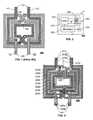
- FIG. 2illustrates an example layout of an interleaved transformer in accordance with this invention.
- FIG. 3illustrates an example handheld communications device that includes an interleaved transformer in accordance with this invention.
- This inventionattempts to increase the inductive coupling between the coils of a transformer without substantially increasing the capacitive coupling between the coils.
- the coilsare preferably located in a common plane, or layer, so that, effectively, only the edges of the conductors in the coils contribute to the capacitance between the coils.
- a plurality of coil segmentsare used to form each of the primary and secondary coils of the transformer. Each plurality of coil segments is connected in parallel with the other coil segments of the plurality forming the primary or secondary coil of the transformer.
- the layout of a plurality of coil segments in lieu of a single coilwill consume substantially greater area than a conventional interleaved transformer, if the same number of windings of equal sized conductors is used in each of the plurality of coil segments as are used in the coil of the conventional transformer.
- the resistance per unit length of a conductor on an integrated circuit or printed circuit boardis inversely proportional to the width of the conductor.
- a maximum resistive lossis defined for each of the coils, and the conductor width is defined accordingly.
- the width of the conductorcan be correspondingly decreased without increasing the resistance of the coil.
- the conductors of each of the two coil segmentscan be reduced to 10 microns wide, without increasing the resistance of the coil.
- the area consumed by the conductors of the plurality of the coil segmentswill be the same as the area consumed by the conductor of a conventional coil, and the only additional area will be the area required to provide insulating space between the conductors.
- the improved coupling achieved by the plurality of coil segmentsgenerally allows for a reduction in the required number of windings per coil. Also, or alternatively, the increased coupling provides for a more efficient energy transfer, and thereby the possible increase in transformer area may be offset by decreases in other components of a system, based on reduced power requirements, a reduced need for noise filtering, and so on.
- the inductance of a planar coilis determined by the effective diameter of the coil and the number of turns in the coil.
- the diameter of the plurality of coil segments that are used in lieu of the single coilneed not substantially increase the effective diameter of the coil.
- the plurality of coil segmentshave the same number of turns as the conventional coil, and thus the inductance of the coil remains substantially the same as the conventional coil.
- FIG. 2illustrates a layout of an example coplanar interleaved transformer 200 comprising two parallel configured coil segments 210 a , 210 b that form a primary coil 210 , and two parallel configured coil segments 220 a , 220 b that form a secondary 220 coil of the transformer 200 in accordance with this invention.
- the coil segmentsare substantially contained on a single plane, or layer, of an integrated circuit, preferably a heavy metal layer, for minimal conductor resistance.
- Segments 202are provided on a different layer that is insulated from the coil layer, thereby allowing for crossovers as required, using vias 205 to connect between layers.
- the conductors forming each of the coil segments 210 a-b , 220 a-bare half the width of the corresponding conductors 110 , 120 in FIG. 1, thereby providing coils 210 , 220 having substantially the same resistance as the corresponding coils 110 , 120 . Because twice as many conductors are coupled between each coil 210 , 220 , the efficiency of the coupling in the transformer 200 is substantially greater than the efficiency of the coupling in the transformer 100 .
- the size of the transformer 200is not substantially larger than the transformer 100 of FIG. 1, thereby providing substantially the same effective diameter for each coil 210 , 220 as the corresponding coil 110 , 120 .
- the inductance of each coil 210 , 220is substantially the same as the inductance of each coil 110 , 120 .
- the innermost coil segments of the transformer 200will have a somewhat smaller diameter than the corresponding coils of the transformer 100 , thereby producing a somewhat lower inductance.
- each additional coil segmentallows the width of the conductor used to be correspondingly decreased, thereby maintaining the overall size of the transformer substantially constant. That is, for example, with three parallel coil segments, the width of each conductor is one-third of the width of the conventional transformer 100 of FIG. 1; four parallel coil segments will use conductors of one-quarter width, and so on. Only when the accumulation of spacing between conductors becomes substantial, or the determined reduced width is less than the required minimum conductor size allowed by the manufacturing technology, will the size of the transformer change substantially compared to that of FIG. 1 .
- Each of the coil segments 210 a , 210 b and 220 a , 220 b forming each of the primary 210 and secondary 220 coils, respectively,are preferably of substantially equal length and equal inductance, so as to balance the current flow between the parallel paths.
- the conductors of the coil segmentsare arranged, from the outer edge to the inner edge, in the order of: 210 a , 220 a , 210 b , 220 b , 210 a , 220 a , 210 b , 220 b , hereinafter termed an aa-bb-aa-bb arrangement, indicating that the “a” primary and secondary coils are at the outer loop, then the “b” primary and secondary coils, then the “a” coils again, then the “b” coils.
- the “a” coilswill be somewhat longer in length than the “b” coils.
- An alternative aa-bb-bb-aa arrangementcould provide more balanced lengths, although the equality of lengths is not critical, and need only be approximate.
- FIG. 2Illustrated in FIG. 2 is an optional center-tap 210 c on the primary coil 210 ; alternatively, or additionally, a center-tap can be provided on the secondary coil 220 . As would be evident to one of ordinary skill in the art, other taps, such as ratioed taps can also be provided.
- FIG. 3illustrates a typical handheld transmitter that includes a transformer 200 that is located on the same integrated circuit 310 that contains a conventional transmission amplifier 315 .
- the centertapped primary coil of the transformer 200is driven by the amplifier, and a capacitor 320 is coupled to the secondary coil, to form a resonant circuit that is coupled to a transmitting antenna 325 .
- the resonant frequency of a resonant circuitis determined by the product of the inductance and the capacitance, and the quality of the resonant circuit is determined by the resistance in the resonant circuit.
- a modulator 330that receives, for example, voice input from a microphone 335 , provides the input to the amplifier 315 .
- the modulator 330may be included on the same integrated circuit 310 as the amplifier 315 .
- FIG. 2illustrates two parallel coil segments (“a” and “b”) forming each of the primary 210 and secondary 220 coils, although the principles of this invention are applicable to any number of parallel coils.
- three coilsmay be arranged as aa-bb-cc-aa-bb-cc, or aa-bb-cc-bb-cc-aa, or other combinations that tend to provide approximately equal coil lengths.
- one coil 210 , 220may have one number of parallel coils, and the other coil may have a different number of parallel coils.
- the arrangementcould be a-A-b-B-c-a-A-b-B-c, for a 3:2 turns ratio. Note, however, that the efficiency of the interlaced transformer is best at a 1:1 turns ratio, because the repeated conductors of one coil (the “c-a” arrangement in this example) does not occur in a 1:1 turns ratio arrangement.
Landscapes
- Engineering & Computer Science (AREA)
- Power Engineering (AREA)
- Microelectronics & Electronic Packaging (AREA)
- Coils Or Transformers For Communication (AREA)
Abstract
Description
1. Field of the Invention
This invention relates to the field of integrated circuits, and in particular to the design of an interleaved transformer device with improved coupling characteristics.
2. Description of Related Art
A transformer comprises two coils of wire that are electromagnetically coupled. An AC signal applied to one of the coils of wire, nominally termed the primary coil, induces a corresponding AC signal on the other coil, nominally termed the secondary coil. The efficiency of the coupling between the coils determines the efficiency of the energy transfer from one coil to the other, as well as the overall noise sensitivity of the transformer.
Transformers are generally used to provide electrical isolation between signals, often to allow for a change of voltage reference planes. Transformers are also often used to couple a signal to a resonant L-C circuit, one of the coils of the transformer providing the inductance, or a portion of the inductance. Radio-frequency (RF) transmitters typically include an RF transformer that couples an output stage to a resonant antenna stage.
Discrete transformers include two coils of wire that are wrapped around a core, which may be an air core, or a ferrite core, for improved coupling efficiency. The coils may be stacked, one atop the other on a common core, or may be wrapped one after the other on the common core, or may be formed by interleaving the wires and then wrapping the combination of the wires about the common core.
Stacked and interleaved transformers may be similarly constructed on multi-layer integrated circuits. Stacked coils can be implemented by forming conductive spirals of conductors on each of two layers, one atop the other. A transformer with interleaved coils is formed by laying the conductors of each coil adjacent to each other on the same conductive layer in a spiral pattern. A stacked core exhibits a high capacitance, because the two co-located spirals, one atop the other, effectively form two plates of a capacitor. This capacitive coupling between the coils introduces phase-shift and amplitude errors during the coupling process. In a transformer with interleaved coils, because the conductors are adjacent each other, rather than atop each other as in the stacked embodiment, the capacitive coupling is substantially less, thereby providing less phase-shift and less amplitude error.
FIG. 1 illustrates an example layout of a coplanar interleavedtransformer 100.Terminals first coil 110, andterminals second coil 120. Different cross-hatching is used for the conductors of each coil, for ease of illustration and understanding. Both coils are substantially on the same integrated circuit layer, preferably the heavy metallic layer, for minimal resistance losses.Interconnection segments 102 are located on a second circuit layer, to allow for insulated cross-overs of routing, as required. Connections between layers are illustrated by thecircular areas 105, for ease of distinction in the illustrations. The coplanar interleaved transformer of FIG. 1 provides less capacitive coupling between coils than a stacked configuration, but consumes more area than a stacked configuration, and provides less efficient coupling than the stacked configuration.
U.S. Pat. No. 5,543,773, “TRANSFORMERS AND COUPLED INDUCTORS WITH OPTIMUM INTERLEAVING OF WINDINGS”, issued Aug. 6, 1996 to Peter D. Evans and William J. B. Heffernan, teaches the interleaving of parallel segments of one of the coils, to achieve different turn-ratios, and is incorporated by reference herein. The referenced patent includes a coplanar transformer having a continuous primary coil spiral wound about a ferrite core, with interleaved segments of a secondary coil that are connected in parallel to effect a non-unity turns ratio. To improve the coupling between the primary and secondary coils, additional turns are conventionally used. For example, in the referenced patent, a 12:2 turns-ratio of actual turns is used to effect a 6:1 electrical turns-ratio; a 12:6 actual turns-ratio is used to effect a 2:1 turns-ratio, and so on. These additional actual turns increase the inductive coupling between the coils, while still maintaining the desired electrical turns-ratio that determines the ratio between input and output currents (n1*i1=n2*i2). Increasing the number of actual turns, however, increases the resistance, as well as the inductance, of each coil. In a coplanar transformer, increasing the number of actual turns substantially increases the area consumed by the transformer.
It is an object of this invention to provide a transformer structure that provides the relatively low capacitance of a conventional coplanar interleaved transformer, but with improved coupling efficiency and effectiveness. It is a further object of the invention to provide a coplanar transformer structure that provides improved coupling efficiency and effectiveness, without substantially increasing the inductance or resistance of the coils.
These objects and others are achieved by splitting each coil into two or more parallel segments, and interleaving the multiple segments of each coil with each other to form an interleaved coil that has a greater coupling efficiency than a non-segmented interleaved transformer. Because the multiple segments of each coil are connected in parallel, the resistance of the coil is decreased, or, the width of the conductor used to form the coil can be decreased while maintaining the same resistance. By reducing the width of the conductors used in a coplanar transformer, the additional parallel segments can be placed in substantially the same area as the conventional transformer, thereby maintaining the same inductance. To provide for maximum efficiency, each segment of each coil is embodied so as to have substantially equal length as each other segment of the coil.
The invention is explained in further detail, and by way of example, with reference to the accompanying drawings wherein:
FIG. 1 illustrates an example layout of a prior art interleaved transformer; and
FIG. 2 illustrates an example layout of an interleaved transformer in accordance with this invention.
FIG. 3 illustrates an example handheld communications device that includes an interleaved transformer in accordance with this invention.
Throughout the drawings, the same reference numerals indicate similar or corresponding features or functions.
This invention attempts to increase the inductive coupling between the coils of a transformer without substantially increasing the capacitive coupling between the coils. To minimize the capacitive coupling, the coils are preferably located in a common plane, or layer, so that, effectively, only the edges of the conductors in the coils contribute to the capacitance between the coils. To increase the inductive coupling, a plurality of coil segments are used to form each of the primary and secondary coils of the transformer. Each plurality of coil segments is connected in parallel with the other coil segments of the plurality forming the primary or secondary coil of the transformer.
The layout of a plurality of coil segments in lieu of a single coil will consume substantially greater area than a conventional interleaved transformer, if the same number of windings of equal sized conductors is used in each of the plurality of coil segments as are used in the coil of the conventional transformer. As is commonly known, the resistance per unit length of a conductor on an integrated circuit or printed circuit board is inversely proportional to the width of the conductor. In a conventional transformer embodiment, a maximum resistive loss is defined for each of the coils, and the conductor width is defined accordingly. In accordance with this invention, because each of the plurality of coil segments forming the primary and secondary coils are connected in parallel, the width of the conductor can be correspondingly decreased without increasing the resistance of the coil. That is, for example, if the conductor of a coil of a conventional transformer is 20 microns wide, and if two coil segments are connected in parallel to form the coil in accordance with this invention, the conductors of each of the two coil segments can be reduced to 10 microns wide, without increasing the resistance of the coil. Thus, the area consumed by the conductors of the plurality of the coil segments will be the same as the area consumed by the conductor of a conventional coil, and the only additional area will be the area required to provide insulating space between the conductors.
In accordance with this invention, the improved coupling achieved by the plurality of coil segments generally allows for a reduction in the required number of windings per coil. Also, or alternatively, the increased coupling provides for a more efficient energy transfer, and thereby the possible increase in transformer area may be offset by decreases in other components of a system, based on reduced power requirements, a reduced need for noise filtering, and so on.
As is known in the art, the inductance of a planar coil is determined by the effective diameter of the coil and the number of turns in the coil. By using narrower conductors in the coil segments, as discussed above, the diameter of the plurality of coil segments that are used in lieu of the single coil need not substantially increase the effective diameter of the coil. In accordance with this invention, the plurality of coil segments have the same number of turns as the conventional coil, and thus the inductance of the coil remains substantially the same as the conventional coil. As discussed further below, there will be a slight reduction in the inductance of the coil, caused by the lower inductance of the innermost coil segment, but this lower inductance is somewhat offset by the higher coupling factor achieved by this invention.
FIG. 2 illustrates a layout of an example coplanar interleavedtransformer 200 comprising two parallel configuredcoil segments primary coil 210, and two parallel configuredcoil segments transformer 200 in accordance with this invention. As in FIG. 1, the coil segments are substantially contained on a single plane, or layer, of an integrated circuit, preferably a heavy metal layer, for minimal conductor resistance. Segments202 are provided on a different layer that is insulated from the coil layer, thereby allowing for crossovers as required, usingvias 205 to connect between layers.
In accordance with this invention, because there are two coil segments per coil, the conductors forming each of thecoil segments 210a-b,220a-bare half the width of the correspondingconductors coils coils coil transformer 200 is substantially greater than the efficiency of the coupling in thetransformer 100.
By using twoconductors 210a-b,220a-bof half width for eachcoil transformer 200 is not substantially larger than thetransformer 100 of FIG. 1, thereby providing substantially the same effective diameter for eachcoil coil coil coil transformer 200 will have a somewhat smaller diameter than the corresponding coils of thetransformer 100, thereby producing a somewhat lower inductance. This lower inductance, being in parallel with the inductance of the other coil segments, reduces the total inductance of the coil. This reduction, however, is somewhat offset by the improved coupling factor of the paralleled coil segments (effective inductance=inductance*(1+coupling factor)).
The efficiency of the coupling between thecoils conventional transformer 100 of FIG. 1; four parallel coil segments will use conductors of one-quarter width, and so on. Only when the accumulation of spacing between conductors becomes substantial, or the determined reduced width is less than the required minimum conductor size allowed by the manufacturing technology, will the size of the transformer change substantially compared to that of FIG.1.
Each of thecoil segments
Illustrated in FIG. 2 is an optional center-tap 210con theprimary coil 210; alternatively, or additionally, a center-tap can be provided on thesecondary coil 220. As would be evident to one of ordinary skill in the art, other taps, such as ratioed taps can also be provided.
This invention is particularly well suited for handheld devices, such as cell telephones, where light weight and compact design are preferred. FIG. 3 illustrates a typical handheld transmitter that includes atransformer 200 that is located on the sameintegrated circuit 310 that contains aconventional transmission amplifier 315. As illustrated, the centertapped primary coil of thetransformer 200 is driven by the amplifier, and acapacitor 320 is coupled to the secondary coil, to form a resonant circuit that is coupled to a transmitting antenna325. As is known in the art, the resonant frequency of a resonant circuit is determined by the product of the inductance and the capacitance, and the quality of the resonant circuit is determined by the resistance in the resonant circuit. Amodulator 330 that receives, for example, voice input from amicrophone 335, provides the input to theamplifier 315. Optionally, themodulator 330 may be included on the sameintegrated circuit 310 as theamplifier 315.
By providing the plurality of paralleled coil segments that substantially maintain the inductance and resistance of the conventional transformer, but with increased coupling efficiency, improved performance of thedevice 300 can be achieved via this invention without introducing a substantial design change.
FIG. 2 illustrates two parallel coil segments (“a” and “b”) forming each of the primary210 and secondary220 coils, although the principles of this invention are applicable to any number of parallel coils. For example, three coils may be arranged as aa-bb-cc-aa-bb-cc, or aa-bb-cc-bb-cc-aa, or other combinations that tend to provide approximately equal coil lengths. In like manner, to achieve a different turns-ratio, onecoil
The foregoing merely illustrates the principles of the invention. It will thus be appreciated that those skilled in the art will be able to devise various arrangements which, although not explicitly described or shown herein, embody the principles of the invention and are thus within the spirit and scope of the following claims.
Claims (14)
1. A transformer comprising:
a primary coil and
a secondary coil,
wherein
the primary and secondary coils are coplanar, and
each of the primary and secondary coils includes
a plurality of coil segments that are configured to provide parallel current paths to input terminals of the corresponding primary and secondary coils,
each of the plurality of coil segments also being coplanar.
2. The transformer ofclaim 1 , wherein
the coplanar primary and secondary coils are located on a common layer of an integrated circuit.
3. The transformer ofclaim 1 , further including
a center tap terminal on at least one of the primary and secondary coils.
4. The transformer ofclaim 1 , wherein
each of the plurality of coil segments comprises a conductor of approximately equal length to conductors of other coil segments of the plurality of coil segments.
5. The transformer ofclaim 1 , wherein
each of the primary and secondary coils include an equal number of coil segments.
6. An integrated circuit comprising
a transformer that includes:
a primary coil and
a secondary coil,
wherein
the primary and secondary coils are coplanar, and
each of the primary and secondary coils includes
a plurality of coil segments that are configured to provide parallel current paths to input terminals of the corresponding primary and secondary coils,
each of the plurality of coil segments also being coplanar.
7. The integrated circuit ofclaim 6 , wherein
the coplanar primary and secondary coils are located on a common layer of the integrated circuit.
8. The integrated circuit ofclaim 6 , further including
a center tap terminal on at least one of the primary and secondary coils.
9. The integrated circuit ofclaim 6 , wherein
each of the plurality of coil segments comprises a conductor of approximately equal length to conductors of other coil segments of the plurality of coil segments.
10. The integrated circuit ofclaim 6 , further including
a capacitor that is coupled to at least one of the primary and secondary coils to form a resonant circuit.
11. The integrated circuit ofclaim 6 , wherein
each of the primary and secondary coils include an equal number of coil segments.
12. A mobile device comprising:
an integrated circuit that includes
an amplifier that is configured to provide an output signal, and
a transformer, operably coupled to the amplifier, that includes:
a primary coil that is configured to receive the output signal, and
a secondary coil that is operably coupled to a capacitor to form a resonant circuit, and
an antenna that is operably coupled to the resonant circuit;
wherein
the transformer includes:
a first plurality of coil segments that are operably coupled in parallel to form the primary coil, and
a second plurality of coil segments that are operably coupled in parallel to form the secondary coil; and,
the primary coil and the secondary coil are substantially located on a common layer of the integrated circuit.
13. The mobile device ofclaim 12 , further including:
a modulator that is configured to modulate an input signal to form a modulated input to the amplifier.
14. The mobile device ofclaim 13 , wherein
the modulator is located within the integrated circuit.
Priority Applications (6)
| Application Number | Priority Date | Filing Date | Title |
|---|---|---|---|
| US09/895,920US6577219B2 (en) | 2001-06-29 | 2001-06-29 | Multiple-interleaved integrated circuit transformer |
| JP2003509474AJP2004531089A (en) | 2001-06-29 | 2002-06-20 | Multiple interleaved integrated circuit transformers |
| PCT/IB2002/002531WO2003003390A1 (en) | 2001-06-29 | 2002-06-20 | Multiple-interleaved integrated circuit transformer |
| CNA028131789ACN1522450A (en) | 2001-06-29 | 2002-06-20 | Multiple Interleaved Integrated Circuit Transformers |
| KR10-2003-7002907AKR20040014973A (en) | 2001-06-29 | 2002-06-20 | Multiple-interleaved integrated circuit transformer |
| EP02741017AEP1405319A1 (en) | 2001-06-29 | 2002-06-20 | Multiple-interleaved integrated circuit transformer |
Applications Claiming Priority (1)
| Application Number | Priority Date | Filing Date | Title |
|---|---|---|---|
| US09/895,920US6577219B2 (en) | 2001-06-29 | 2001-06-29 | Multiple-interleaved integrated circuit transformer |
Publications (2)
| Publication Number | Publication Date |
|---|---|
| US20030001709A1 US20030001709A1 (en) | 2003-01-02 |
| US6577219B2true US6577219B2 (en) | 2003-06-10 |
Family
ID=25405294
Family Applications (1)
| Application Number | Title | Priority Date | Filing Date |
|---|---|---|---|
| US09/895,920Expired - Fee RelatedUS6577219B2 (en) | 2001-06-29 | 2001-06-29 | Multiple-interleaved integrated circuit transformer |
Country Status (6)
| Country | Link |
|---|---|
| US (1) | US6577219B2 (en) |
| EP (1) | EP1405319A1 (en) |
| JP (1) | JP2004531089A (en) |
| KR (1) | KR20040014973A (en) |
| CN (1) | CN1522450A (en) |
| WO (1) | WO2003003390A1 (en) |
Cited By (54)
| Publication number | Priority date | Publication date | Assignee | Title |
|---|---|---|---|---|
| US20020175799A1 (en)* | 2001-05-24 | 2002-11-28 | John Nielson | On-chip inductive structure |
| US20030193386A1 (en)* | 2002-04-12 | 2003-10-16 | Bin-Chyi Tseng | Miniaturized common mode filter |
| US20040017278A1 (en)* | 2002-07-23 | 2004-01-29 | Castaneda Jesus A. | On-chip multiple tap transformer and inductor |
| US6798326B2 (en)* | 2001-08-01 | 2004-09-28 | Sony Corporation | Inductor element and integrated circuit employing inductor element |
| US6825749B1 (en)* | 2004-01-26 | 2004-11-30 | National Applied Research Laboratories National Chip Implementation Center | Symmetric crossover structure of two lines for RF integrated circuits |
| US20050003861A1 (en)* | 2003-07-02 | 2005-01-06 | Rodriguez Luis Ricardo | Cordless telephone-to-sound card interface adapter having a hybrid transformer circuit |
| US20050077992A1 (en)* | 2002-09-20 | 2005-04-14 | Gopal Raghavan | Symmetric planar inductor |
| US20050184813A1 (en)* | 2003-10-28 | 2005-08-25 | Kee Scott D. | Multi-primary distributed active transformer oscillator power supply and control |
| US20060033602A1 (en)* | 2004-08-16 | 2006-02-16 | Thomas Mattsson | Variable integrated inductor |
| WO2007019280A3 (en)* | 2005-08-04 | 2007-05-24 | Univ California | Interleaved three-dimensional on-chip differential inductors and transformers |
| US7253712B1 (en) | 2004-08-31 | 2007-08-07 | Theta Microelectronics, Inc. | Integrated high frequency balanced-to-unbalanced transformers |
| US20070247269A1 (en)* | 2004-08-31 | 2007-10-25 | Theta Microelectronics, Inc. | Integrated high frequency BALUN and inductors |
| US7312683B1 (en)* | 2006-08-23 | 2007-12-25 | Via Technologies, Inc. | Symmetrical inductor |
| US20080074228A1 (en)* | 2006-09-22 | 2008-03-27 | Sean Christopher Erickson | Low Mutual Inductance Matched Inductors |
| US20080094166A1 (en)* | 2006-10-19 | 2008-04-24 | United Microelectronics Corp. | High coupling factor transformer and manufacturing method thereof |
| US20080204139A1 (en)* | 2000-10-10 | 2008-08-28 | Abbas Komijani | Reconfigurable distributed active transformers |
| US20080211584A1 (en)* | 2002-03-11 | 2008-09-04 | Seyed-Ali Hajimiri | Cross-differential amplifier |
| US20090015328A1 (en)* | 2007-07-11 | 2009-01-15 | Axiom Microdevices, Inc. | Low offset envelope detector and method of use |
| US20090085705A1 (en)* | 2007-09-27 | 2009-04-02 | Samsung Electro-Mechanics Co., Ltd. | Transformer |
| US20090137215A1 (en)* | 2007-11-28 | 2009-05-28 | Broadcom Corporation | Programmable antenna interface with adjustable transformer and methods for use therewith |
| GB2456065A (en)* | 2008-01-03 | 2009-07-08 | Samsung Electro Mech | A compact integrated impedance-matching output transformer with multiple primary windings connected in parallel |
| US20100060376A1 (en)* | 2008-09-10 | 2010-03-11 | Ying-Chieh Shyu | Balun device |
| US20100060402A1 (en)* | 2008-09-10 | 2010-03-11 | Chen Chi-Han | Balun circuit manufactured by integrate passive device process |
| US20100060403A1 (en)* | 2008-09-10 | 2010-03-11 | Ying-Chieh Shyu | Dual inductance structure |
| US20100060375A1 (en)* | 2008-09-10 | 2010-03-11 | Advanced Semiconductor Engineering, Inc. | Balun circuit manufactured by integrate passive device process |
| US20100148866A1 (en)* | 2007-01-10 | 2010-06-17 | Samsung Electro-Mechanics Company | Systems and Methods for Power Amplifiers with Voltage Boosting Multi-Primary Transformers |
| US20100164667A1 (en)* | 2008-12-31 | 2010-07-01 | Taiwan Semiconductor Manufacturing Co., Ltd. | On-chip transformer balun structures |
| US7812701B2 (en) | 2008-01-08 | 2010-10-12 | Samsung Electro-Mechanics | Compact multiple transformers |
| US20110032067A1 (en)* | 2008-04-10 | 2011-02-10 | Nxp B.V. | 8-shaped inductor |
| US20110043316A1 (en)* | 2008-01-08 | 2011-02-24 | Ki Seok Yang | Overlapping compact multiple transformers |
| US20110102125A1 (en)* | 2008-07-04 | 2011-05-05 | Panasonic Electric Works Co., Ltd., | Plane coil |
| US20110163831A1 (en)* | 2003-07-17 | 2011-07-07 | Broadcom Corporation | Fully Differential, High Q, On-Chip, Impedance Matching Section |
| US20110221522A1 (en)* | 2010-03-12 | 2011-09-15 | Samsung Electro-Mechanics Company, Ltd. | Sharing of inductor interstage matching in parallel amplification system for wireless communication systems |
| US8049563B2 (en) | 2000-10-10 | 2011-11-01 | California Institute Of Technology | Distributed circular geometry power amplifier architecture |
| US20120081203A1 (en)* | 2010-09-30 | 2012-04-05 | Omid Oliaei | System and Method for Multiple Band Transmission |
| DE102011088715A1 (en)* | 2011-04-28 | 2012-10-31 | Globalfoundries Singapore Pte. Ltd. | Integrated transformer |
| US20130135076A1 (en)* | 2011-11-25 | 2013-05-30 | Renesas Electronics Corporation | Transformer |
| US8493168B2 (en)* | 2011-05-26 | 2013-07-23 | Siliconware Precision Industries Co., Ltd. | Asymmetric differential inductor |
| US20130257577A1 (en)* | 2010-12-06 | 2013-10-03 | Alexe Nazarian | Integrated circuit inductors |
| US8760240B2 (en)* | 2010-09-15 | 2014-06-24 | Wilocity, Ltd. | Method for designing coupling-function based millimeter wave electrical elements |
| US20140368307A1 (en)* | 2012-03-16 | 2014-12-18 | Murata Manufacturing Co., Ltd. | Common mode choke coil |
| US20150357978A1 (en)* | 2012-09-23 | 2015-12-10 | Dsp Group Ltd. | Two dimensional integrated power combiner for rf power amplifiers |
| US20160125995A1 (en)* | 2014-10-31 | 2016-05-05 | Qualcomm Incorporated | Array of interleaved 8-shaped transformers with high isolation between adjacent elements |
| US20160233016A1 (en)* | 2015-02-09 | 2016-08-11 | Qualcomm Incorporated | System, apparatus, and method for power amplification transformers |
| US20180040412A1 (en)* | 2016-08-05 | 2018-02-08 | Realtek Semiconductor Corporation | Semiconductor element |
| US20180131332A1 (en)* | 2016-11-04 | 2018-05-10 | Taiwan Semiconductor Manufacturing Co., Ltd. | Wireless receiver |
| US10153078B2 (en) | 2015-10-06 | 2018-12-11 | Realtek Semiconductor Corporation | Integrated inductor structure and integrated transformer structure |
| US10497507B2 (en) | 2016-08-05 | 2019-12-03 | Realtek Semiconductor Corporation | Semiconductor element |
| US10580568B2 (en) | 2016-08-05 | 2020-03-03 | Realtek Semiconductor Corporation | Semiconductor element |
| US10622136B2 (en)* | 2017-10-26 | 2020-04-14 | Arm Ltd | Balanced-to-unbalanced (balun) transformer |
| JP2022048418A (en)* | 2020-09-15 | 2022-03-28 | 三菱電機株式会社 | Connection plate of rotary electric machine stator, stator of rotary electric machine, and rotary electric machine |
| US11309119B2 (en) | 2017-12-12 | 2022-04-19 | Airoha Technology Corp. | On-chip balun transformer |
| US20220375676A1 (en)* | 2021-05-21 | 2022-11-24 | Realtek Semiconductor Corporation | Inductor device |
| US20250182961A1 (en)* | 2015-08-07 | 2025-06-05 | Nucurrent, Inc. | Device Having a Multimode Antenna With Variable Width of Conductive Wire |
Families Citing this family (73)
| Publication number | Priority date | Publication date | Assignee | Title |
|---|---|---|---|---|
| DE60234775D1 (en)* | 2001-08-09 | 2010-01-28 | Nxp Bv | PLANAR INDUCTIVE COMPONENT AND FLAT TRANSFORMER |
| DE10232642B4 (en)* | 2002-07-18 | 2006-11-23 | Infineon Technologies Ag | Integrated transformer arrangement |
| US7852185B2 (en)* | 2003-05-05 | 2010-12-14 | Intel Corporation | On-die micro-transformer structures with magnetic materials |
| KR101005264B1 (en)* | 2003-07-26 | 2011-01-04 | 삼성전자주식회사 | Symmetric Inductor Device |
| GB0321658D0 (en)* | 2003-09-16 | 2003-10-15 | South Bank Univ Entpr Ltd | Bifilar transformer |
| US7262680B2 (en) | 2004-02-27 | 2007-08-28 | Illinois Institute Of Technology | Compact inductor with stacked via magnetic cores for integrated circuits |
| WO2006000973A1 (en)* | 2004-06-23 | 2006-01-05 | Koninklijke Philips Electronics N.V. | Planar inductor |
| US20050289484A1 (en)* | 2004-06-24 | 2005-12-29 | Whitefoot Kevin J | Externalization of coil structure patterns |
| KR100648660B1 (en)* | 2004-10-01 | 2006-11-24 | 삼성전자주식회사 | Facsimile communication interface device which can cut off power supply noise by transformer, and its transformer |
| DE102005014929B4 (en)* | 2005-04-01 | 2008-04-17 | Newlogic Technologies Gmbh | Integrated coil and integrated transformer |
| FR2884985B1 (en)* | 2005-04-20 | 2007-09-21 | Ciprian Sarl | ELECTRICAL SIGNAL AMPLIFIER FOR ULTRASONIC APPLICATIONS |
| US8134548B2 (en)* | 2005-06-30 | 2012-03-13 | Micron Technology, Inc. | DC-DC converter switching transistor current measurement technique |
| JP2009520348A (en)* | 2005-12-19 | 2009-05-21 | コーニンクレッカ フィリップス エレクトロニクス エヌ ヴィ | Interleaved planar transformer primary and secondary windings |
| KR100872514B1 (en)* | 2006-09-18 | 2008-12-08 | 한국과학기술원 | Transformer having a plurality of primary sides and power amplifier using the same |
| CN100585757C (en)* | 2006-11-09 | 2010-01-27 | 联华电子股份有限公司 | High coupling factor transformer and manufacturing method thereof |
| US11687112B2 (en) | 2006-12-06 | 2023-06-27 | Solaredge Technologies Ltd. | Distributed power harvesting systems using DC power sources |
| US9088178B2 (en) | 2006-12-06 | 2015-07-21 | Solaredge Technologies Ltd | Distributed power harvesting systems using DC power sources |
| US8473250B2 (en) | 2006-12-06 | 2013-06-25 | Solaredge, Ltd. | Monitoring of distributed power harvesting systems using DC power sources |
| US11888387B2 (en) | 2006-12-06 | 2024-01-30 | Solaredge Technologies Ltd. | Safety mechanisms, wake up and shutdown methods in distributed power installations |
| US8013472B2 (en) | 2006-12-06 | 2011-09-06 | Solaredge, Ltd. | Method for distributed power harvesting using DC power sources |
| US8963369B2 (en)* | 2007-12-04 | 2015-02-24 | Solaredge Technologies Ltd. | Distributed power harvesting systems using DC power sources |
| US12316274B2 (en) | 2006-12-06 | 2025-05-27 | Solaredge Technologies Ltd. | Pairing of components in a direct current distributed power generation system |
| US11735910B2 (en) | 2006-12-06 | 2023-08-22 | Solaredge Technologies Ltd. | Distributed power system using direct current power sources |
| US8947194B2 (en) | 2009-05-26 | 2015-02-03 | Solaredge Technologies Ltd. | Theft detection and prevention in a power generation system |
| US11855231B2 (en)* | 2006-12-06 | 2023-12-26 | Solaredge Technologies Ltd. | Distributed power harvesting systems using DC power sources |
| US8618692B2 (en) | 2007-12-04 | 2013-12-31 | Solaredge Technologies Ltd. | Distributed power system using direct current power sources |
| US11569659B2 (en) | 2006-12-06 | 2023-01-31 | Solaredge Technologies Ltd. | Distributed power harvesting systems using DC power sources |
| US8319471B2 (en) | 2006-12-06 | 2012-11-27 | Solaredge, Ltd. | Battery power delivery module |
| US8816535B2 (en) | 2007-10-10 | 2014-08-26 | Solaredge Technologies, Ltd. | System and method for protection during inverter shutdown in distributed power installations |
| DE102007027612B4 (en)* | 2007-06-12 | 2009-04-02 | Atmel Duisburg Gmbh | Monolithic integrated inductance |
| CN101377974B (en)* | 2007-08-29 | 2011-06-15 | 光诠科技股份有限公司 | Method for improving mutual inductance effect |
| CN101414508B (en)* | 2007-10-16 | 2011-07-13 | 瑞昱半导体股份有限公司 | Chip type balance-unbalance transformer |
| TWI366261B (en)* | 2007-11-01 | 2012-06-11 | Via Tech Inc | Inductor structure |
| CN105244905B (en) | 2007-12-05 | 2019-05-21 | 太阳能安吉有限公司 | Release mechanism in distributed power device is waken up and method for closing |
| EP2294669B8 (en) | 2008-05-05 | 2016-12-07 | Solaredge Technologies Ltd. | Direct current power combiner |
| KR101453071B1 (en) | 2008-05-14 | 2014-10-23 | 삼성전자주식회사 | Transformer balun and integrated circuit including the same |
| US8742857B2 (en)* | 2008-05-15 | 2014-06-03 | Analog Devices, Inc. | Inductance enhanced rotary traveling wave oscillator circuit and method |
| US8665052B2 (en)* | 2009-08-12 | 2014-03-04 | Mediatek Inc. | Transformer-based circuit with compact and/or symmetrical layout design |
| US12418177B2 (en) | 2009-10-24 | 2025-09-16 | Solaredge Technologies Ltd. | Distributed power system using direct current power sources |
| KR101141471B1 (en)* | 2010-09-16 | 2012-05-04 | 삼성전기주식회사 | Transformer |
| US10673229B2 (en) | 2010-11-09 | 2020-06-02 | Solaredge Technologies Ltd. | Arc detection and prevention in a power generation system |
| GB2485527B (en) | 2010-11-09 | 2012-12-19 | Solaredge Technologies Ltd | Arc detection and prevention in a power generation system |
| KR101465968B1 (en)* | 2010-12-20 | 2014-11-28 | 인텔 코포레이션 | A chip apparatus, a method of making same, and a computer system |
| GB2483317B (en) | 2011-01-12 | 2012-08-22 | Solaredge Technologies Ltd | Serially connected inverters |
| CN102176453B (en)* | 2011-03-17 | 2013-04-24 | 杭州电子科技大学 | Vertical-structure on-chip integrated transformer |
| FR2978595A1 (en)* | 2011-07-28 | 2013-02-01 | St Microelectronics Crolles 2 | TRANSFORMER OF THE SYMMETRIC-DISSYMETRIC TYPE |
| GB2498365A (en) | 2012-01-11 | 2013-07-17 | Solaredge Technologies Ltd | Photovoltaic module |
| US9853565B2 (en) | 2012-01-30 | 2017-12-26 | Solaredge Technologies Ltd. | Maximized power in a photovoltaic distributed power system |
| GB2498791A (en) | 2012-01-30 | 2013-07-31 | Solaredge Technologies Ltd | Photovoltaic panel circuitry |
| GB2498790A (en) | 2012-01-30 | 2013-07-31 | Solaredge Technologies Ltd | Maximising power in a photovoltaic distributed power system |
| US9548619B2 (en) | 2013-03-14 | 2017-01-17 | Solaredge Technologies Ltd. | Method and apparatus for storing and depleting energy |
| CN103681539B (en)* | 2013-12-18 | 2016-06-08 | 江阴长电先进封装有限公司 | Packaging structure and packaging method of integrated common-mode inductor |
| CN103928438B (en)* | 2014-04-04 | 2016-11-16 | 豪威科技(上海)有限公司 | On-chip transformer, its layout structure, transmission circuit and transceiver circuit |
| US10116259B2 (en) | 2014-05-29 | 2018-10-30 | Qualcomm Incorporated | Inductor-enclosed voltage-controlled oscillators |
| TWI622068B (en)* | 2015-02-02 | 2018-04-21 | 瑞昱半導體股份有限公司 | Integrated inductor structure |
| CN105990012B (en)* | 2015-03-06 | 2018-02-09 | 瑞昱半导体股份有限公司 | Transformer suitable for oscillator and winding method of transformer |
| US11205848B2 (en) | 2015-08-07 | 2021-12-21 | Nucurrent, Inc. | Method of providing a single structure multi mode antenna having a unitary body construction for wireless power transmission using magnetic field coupling |
| US10063100B2 (en) | 2015-08-07 | 2018-08-28 | Nucurrent, Inc. | Electrical system incorporating a single structure multimode antenna for wireless power transmission using magnetic field coupling |
| CN208423175U (en)* | 2015-11-30 | 2019-01-22 | 株式会社村田制作所 | Antenna device and electronic apparatus |
| US11227825B2 (en) | 2015-12-21 | 2022-01-18 | Intel Corporation | High performance integrated RF passives using dual lithography process |
| US11177663B2 (en) | 2016-04-05 | 2021-11-16 | Solaredge Technologies Ltd. | Chain of power devices |
| US12057807B2 (en) | 2016-04-05 | 2024-08-06 | Solaredge Technologies Ltd. | Chain of power devices |
| US11018623B2 (en) | 2016-04-05 | 2021-05-25 | Solaredge Technologies Ltd. | Safety switch for photovoltaic systems |
| US20170345559A1 (en)* | 2016-05-31 | 2017-11-30 | Globalfoundries Inc. | "Interleaved Transformer and Method of Making the Same" |
| CN107731485B (en)* | 2016-08-12 | 2020-08-18 | 瑞昱半导体股份有限公司 | Semiconductor device with a plurality of semiconductor chips |
| US11049639B2 (en) | 2017-02-13 | 2021-06-29 | Analog Devices, Inc. | Coupled coils with lower far field radiation and higher noise immunity |
| TWI681419B (en)* | 2019-06-13 | 2020-01-01 | 瑞昱半導體股份有限公司 | Inductor device |
| TWI722946B (en)* | 2019-09-11 | 2021-03-21 | 瑞昱半導體股份有限公司 | Semiconductor device |
| US11651887B2 (en) | 2020-05-27 | 2023-05-16 | Infineon Technologies Ag | Stacked and interleaved transformer layout |
| CN112259348B (en)* | 2020-10-21 | 2022-01-11 | 清华大学 | An integrated inductive device and amplifier |
| TWI748878B (en)* | 2020-11-18 | 2021-12-01 | 瑞昱半導體股份有限公司 | Transformer device |
| CN116168918A (en)* | 2021-11-25 | 2023-05-26 | 瑞昱半导体股份有限公司 | Inductive device |
| US20240304545A1 (en)* | 2023-03-10 | 2024-09-12 | Qualcomm Incorporated | Coupled inductors through substrate-assembly process and/or wafer-level process |
Citations (11)
| Publication number | Priority date | Publication date | Assignee | Title |
|---|---|---|---|---|
| US4816784A (en)* | 1988-01-19 | 1989-03-28 | Northern Telecom Limited | Balanced planar transformers |
| US5061910A (en) | 1989-09-18 | 1991-10-29 | Motorola, Inc. | Balun transformers |
| US5477204A (en)* | 1994-07-05 | 1995-12-19 | Motorola, Inc. | Radio frequency transformer |
| US5543773A (en) | 1990-09-07 | 1996-08-06 | Electrotech Instruments Limited | Transformers and coupled inductors with optimum interleaving of windings |
| US5570074A (en) | 1995-05-30 | 1996-10-29 | General Electric Company | Very low leakage inductance, single-laminate transformer |
| US5625883A (en)* | 1993-12-24 | 1997-04-29 | U.S. Philips Corporation | System for wireless information transmission between two different rooms |
| WO1999031682A2 (en) | 1997-12-17 | 1999-06-24 | Koninklijke Philips Electronics N.V. | Planar transformer |
| WO2000045399A1 (en) | 1999-01-28 | 2000-08-03 | Broadcom Corporation | Multi-track integrated spiral inductor |
| US6150914A (en) | 1995-12-05 | 2000-11-21 | Robert Bosch Gmbh | Transformer with divided primary winding used in a blocking-oscillator supply circuit |
| US6175727B1 (en)* | 1998-01-09 | 2001-01-16 | Texas Instruments Israel Ltd. | Suspended printed inductor and LC-type filter constructed therefrom |
| US6236297B1 (en)* | 1998-07-08 | 2001-05-22 | Winbond Electronics Corp. | Combinational inductor |
Family Cites Families (4)
| Publication number | Priority date | Publication date | Assignee | Title |
|---|---|---|---|---|
| KR960006848B1 (en)* | 1990-05-31 | 1996-05-23 | 가부시끼가이샤 도시바 | Planar magnetic elements |
| JP3725599B2 (en)* | 1995-09-07 | 2005-12-14 | 株式会社東芝 | Planar magnetic element |
| JP2000058341A (en)* | 1998-08-06 | 2000-02-25 | Nagano Japan Radio Co | Planar transformer |
| JP2000082621A (en)* | 1998-09-07 | 2000-03-21 | Fuji Electric Co Ltd | Plane transformer |
- 2001
- 2001-06-29USUS09/895,920patent/US6577219B2/ennot_activeExpired - Fee Related
- 2002
- 2002-06-20KRKR10-2003-7002907Apatent/KR20040014973A/ennot_activeWithdrawn
- 2002-06-20WOPCT/IB2002/002531patent/WO2003003390A1/ennot_activeApplication Discontinuation
- 2002-06-20EPEP02741017Apatent/EP1405319A1/ennot_activeWithdrawn
- 2002-06-20CNCNA028131789Apatent/CN1522450A/enactivePending
- 2002-06-20JPJP2003509474Apatent/JP2004531089A/ennot_activeAbandoned
Patent Citations (11)
| Publication number | Priority date | Publication date | Assignee | Title |
|---|---|---|---|---|
| US4816784A (en)* | 1988-01-19 | 1989-03-28 | Northern Telecom Limited | Balanced planar transformers |
| US5061910A (en) | 1989-09-18 | 1991-10-29 | Motorola, Inc. | Balun transformers |
| US5543773A (en) | 1990-09-07 | 1996-08-06 | Electrotech Instruments Limited | Transformers and coupled inductors with optimum interleaving of windings |
| US5625883A (en)* | 1993-12-24 | 1997-04-29 | U.S. Philips Corporation | System for wireless information transmission between two different rooms |
| US5477204A (en)* | 1994-07-05 | 1995-12-19 | Motorola, Inc. | Radio frequency transformer |
| US5570074A (en) | 1995-05-30 | 1996-10-29 | General Electric Company | Very low leakage inductance, single-laminate transformer |
| US6150914A (en) | 1995-12-05 | 2000-11-21 | Robert Bosch Gmbh | Transformer with divided primary winding used in a blocking-oscillator supply circuit |
| WO1999031682A2 (en) | 1997-12-17 | 1999-06-24 | Koninklijke Philips Electronics N.V. | Planar transformer |
| US6175727B1 (en)* | 1998-01-09 | 2001-01-16 | Texas Instruments Israel Ltd. | Suspended printed inductor and LC-type filter constructed therefrom |
| US6236297B1 (en)* | 1998-07-08 | 2001-05-22 | Winbond Electronics Corp. | Combinational inductor |
| WO2000045399A1 (en) | 1999-01-28 | 2000-08-03 | Broadcom Corporation | Multi-track integrated spiral inductor |
Cited By (120)
| Publication number | Priority date | Publication date | Assignee | Title |
|---|---|---|---|---|
| US8049563B2 (en) | 2000-10-10 | 2011-11-01 | California Institute Of Technology | Distributed circular geometry power amplifier architecture |
| US20080204139A1 (en)* | 2000-10-10 | 2008-08-28 | Abbas Komijani | Reconfigurable distributed active transformers |
| US7733183B2 (en) | 2000-10-10 | 2010-06-08 | California Institute Of Technology | Reconfigurable distributed active transformers |
| US20020175799A1 (en)* | 2001-05-24 | 2002-11-28 | John Nielson | On-chip inductive structure |
| US6867677B2 (en)* | 2001-05-24 | 2005-03-15 | Nokia Corporation | On-chip inductive structure |
| US6798326B2 (en)* | 2001-08-01 | 2004-09-28 | Sony Corporation | Inductor element and integrated circuit employing inductor element |
| US7999621B2 (en) | 2002-03-11 | 2011-08-16 | California Institute Of Technology | Cross-differential amplifier |
| US7646249B2 (en) | 2002-03-11 | 2010-01-12 | California Institute Of Technology | Cross-differential amplifier |
| US20080211584A1 (en)* | 2002-03-11 | 2008-09-04 | Seyed-Ali Hajimiri | Cross-differential amplifier |
| US8362839B2 (en) | 2002-03-11 | 2013-01-29 | California Institute Of Technology | Cross-differential amplifier |
| US20100117733A1 (en)* | 2002-03-11 | 2010-05-13 | California Institute Of Technology | Cross-differential amplifier |
| US20030193386A1 (en)* | 2002-04-12 | 2003-10-16 | Bin-Chyi Tseng | Miniaturized common mode filter |
| US20040108927A1 (en)* | 2002-07-23 | 2004-06-10 | Castaneda Jesus A. | On-chip multiple tap transformer and inductor |
| US7088214B2 (en)* | 2002-07-23 | 2006-08-08 | Broadcom Corporation | On-chip multiple tap transformer and inductor |
| US6707367B2 (en)* | 2002-07-23 | 2004-03-16 | Broadcom, Corp. | On-chip multiple tap transformer and inductor |
| US20040017278A1 (en)* | 2002-07-23 | 2004-01-29 | Castaneda Jesus A. | On-chip multiple tap transformer and inductor |
| US20050077992A1 (en)* | 2002-09-20 | 2005-04-14 | Gopal Raghavan | Symmetric planar inductor |
| US6970557B2 (en)* | 2003-07-02 | 2005-11-29 | Nvg, Inc. | Cordless telephone-to-sound card interface adapter having a hybrid transformer circuit |
| US20050003861A1 (en)* | 2003-07-02 | 2005-01-06 | Rodriguez Luis Ricardo | Cordless telephone-to-sound card interface adapter having a hybrid transformer circuit |
| US20110163831A1 (en)* | 2003-07-17 | 2011-07-07 | Broadcom Corporation | Fully Differential, High Q, On-Chip, Impedance Matching Section |
| US8274353B2 (en)* | 2003-07-17 | 2012-09-25 | Broadcom Corporation | Fully differential, high Q, on-chip, impedance matching section |
| US7760025B2 (en)* | 2003-10-28 | 2010-07-20 | Axiom Microdevices, Inc. | Multi-primary distributed active transformer amplifier power supply and control |
| USRE45974E1 (en)* | 2003-10-28 | 2016-04-12 | Axiom Microdevices, Inc. | Multi-primary distributed active transformer amplifier power supply and control |
| US20100283548A1 (en)* | 2003-10-28 | 2010-11-11 | Kee Scott D | Multi-primary distributed active transformer amplifier power supply and control |
| US8242855B2 (en)* | 2003-10-28 | 2012-08-14 | Axiom Microdevices, Inc. | Multi-primary distributed active transformer amplifier power supply and control |
| US7471153B2 (en) | 2003-10-28 | 2008-12-30 | Axiom Microdevices, Inc. | Multi-primary distributed active transformer amplifier power supply and control |
| US7915960B2 (en)* | 2003-10-28 | 2011-03-29 | Axiom Microdevices, Inc. | Multi-primary distributed active transformer amplifier power supply and control |
| US20050189995A1 (en)* | 2003-10-28 | 2005-09-01 | Kee Scott D. | Multi-primary distributed active transformer amplifier power supply and control |
| US20090102592A1 (en)* | 2003-10-28 | 2009-04-23 | Kee Scott D | Multi-Primary Distributed Active Transformer Amplifier Power Supply and Control |
| US20110175685A1 (en)* | 2003-10-28 | 2011-07-21 | Kee Scott D | Multi-primary distributed active transformer amplifier power supply and control |
| US20050184813A1 (en)* | 2003-10-28 | 2005-08-25 | Kee Scott D. | Multi-primary distributed active transformer oscillator power supply and control |
| EP1678821B1 (en)* | 2003-10-28 | 2019-05-01 | Axiom Microdevices, Inc. | Multi-primary distributed active transformer amplifier power supply and control |
| US6825749B1 (en)* | 2004-01-26 | 2004-11-30 | National Applied Research Laboratories National Chip Implementation Center | Symmetric crossover structure of two lines for RF integrated circuits |
| US20060033602A1 (en)* | 2004-08-16 | 2006-02-16 | Thomas Mattsson | Variable integrated inductor |
| US7432794B2 (en)* | 2004-08-16 | 2008-10-07 | Telefonaktiebolaget L M Ericsson (Publ) | Variable integrated inductor |
| US7253712B1 (en) | 2004-08-31 | 2007-08-07 | Theta Microelectronics, Inc. | Integrated high frequency balanced-to-unbalanced transformers |
| US20110018672A1 (en)* | 2004-08-31 | 2011-01-27 | Theta Microelectronics, Inc. | Integrated High Frequency BALUN and Inductors |
| US20070247269A1 (en)* | 2004-08-31 | 2007-10-25 | Theta Microelectronics, Inc. | Integrated high frequency BALUN and inductors |
| US8505193B2 (en) | 2004-08-31 | 2013-08-13 | Theta Microelectronics, Inc. | Method for manufacturing an on-chip BALUN transformer |
| US8183970B2 (en) | 2004-08-31 | 2012-05-22 | Theta Microelectronics, Inc. | Integrated high frequency BALUN and inductors |
| US7808356B2 (en) | 2004-08-31 | 2010-10-05 | Theta Microelectronics, Inc. | Integrated high frequency BALUN and inductors |
| US20080272875A1 (en)* | 2005-08-04 | 2008-11-06 | Daquan Huang | "Interleaved Three-Dimensional On-Chip Differential Inductors and Transformers |
| US8325001B2 (en) | 2005-08-04 | 2012-12-04 | The Regents Of The University Of California | Interleaved three-dimensional on-chip differential inductors and transformers |
| WO2007019280A3 (en)* | 2005-08-04 | 2007-05-24 | Univ California | Interleaved three-dimensional on-chip differential inductors and transformers |
| TWI408796B (en)* | 2005-08-04 | 2013-09-11 | Univ California | Interleaved three-dimensional on-chip differential inductors and transformers |
| US7312683B1 (en)* | 2006-08-23 | 2007-12-25 | Via Technologies, Inc. | Symmetrical inductor |
| US20080074228A1 (en)* | 2006-09-22 | 2008-03-27 | Sean Christopher Erickson | Low Mutual Inductance Matched Inductors |
| US7535330B2 (en)* | 2006-09-22 | 2009-05-19 | Lsi Logic Corporation | Low mutual inductance matched inductors |
| US20080094166A1 (en)* | 2006-10-19 | 2008-04-24 | United Microelectronics Corp. | High coupling factor transformer and manufacturing method thereof |
| US7656264B2 (en) | 2006-10-19 | 2010-02-02 | United Microelectronics Corp. | High coupling factor transformer and manufacturing method thereof |
| US20100148866A1 (en)* | 2007-01-10 | 2010-06-17 | Samsung Electro-Mechanics Company | Systems and Methods for Power Amplifiers with Voltage Boosting Multi-Primary Transformers |
| US7880547B2 (en) | 2007-01-10 | 2011-02-01 | Samsung Electro-Mechanics | Systems and methods for power amplifiers with voltage boosting multi-primary transformers |
| US7710197B2 (en) | 2007-07-11 | 2010-05-04 | Axiom Microdevices, Inc. | Low offset envelope detector and method of use |
| US20090015328A1 (en)* | 2007-07-11 | 2009-01-15 | Axiom Microdevices, Inc. | Low offset envelope detector and method of use |
| US7675397B2 (en)* | 2007-09-27 | 2010-03-09 | Samsung Electro-Mechanics Co., Ltd. | Transformer |
| DE102008016876B4 (en) | 2007-09-27 | 2021-10-14 | Samsung Electro-Mechanics Co., Ltd. | transformer |
| US20090085705A1 (en)* | 2007-09-27 | 2009-04-02 | Samsung Electro-Mechanics Co., Ltd. | Transformer |
| US20090137215A1 (en)* | 2007-11-28 | 2009-05-28 | Broadcom Corporation | Programmable antenna interface with adjustable transformer and methods for use therewith |
| US7979043B2 (en)* | 2007-11-28 | 2011-07-12 | Broadcom Corporation | Programmable antenna interface with adjustable transformer and methods for use therewith |
| US7936215B2 (en) | 2008-01-03 | 2011-05-03 | Samsung-Electro Mechanics | Multi-segment primary and multi-turn secondary transformer for power amplifier systems |
| US7576607B2 (en) | 2008-01-03 | 2009-08-18 | Samsung Electro-Mechanics | Multi-segment primary and multi-turn secondary transformer for power amplifier systems |
| GB2456065A (en)* | 2008-01-03 | 2009-07-08 | Samsung Electro Mech | A compact integrated impedance-matching output transformer with multiple primary windings connected in parallel |
| CN101488729B (en)* | 2008-01-03 | 2011-10-05 | 佐治亚科技研究公司 | Multi-segment primary and multi-turn secondary transformers for power amplifier systems |
| GB2456065B (en)* | 2008-01-03 | 2011-01-26 | Samsung Electro Mech | Multi-segment primary and multi turn secondary transformer for power amplifier systems |
| US20090174477A1 (en)* | 2008-01-03 | 2009-07-09 | Chang-Ho Lee | Multi-segment primary and multi-turn secondary transformer for power amplifier systems |
| US20090184786A1 (en)* | 2008-01-03 | 2009-07-23 | Chang-Ho Lee | Multi-segment primary and multi-turn secondary transformer for power amplifier systems |
| US8044759B2 (en) | 2008-01-08 | 2011-10-25 | Samsung Electro-Mechanics | Overlapping compact multiple transformers |
| US7812701B2 (en) | 2008-01-08 | 2010-10-12 | Samsung Electro-Mechanics | Compact multiple transformers |
| US20110043316A1 (en)* | 2008-01-08 | 2011-02-24 | Ki Seok Yang | Overlapping compact multiple transformers |
| US8183971B2 (en)* | 2008-04-10 | 2012-05-22 | Nxp B.V. | 8-shaped inductor |
| US20110032067A1 (en)* | 2008-04-10 | 2011-02-10 | Nxp B.V. | 8-shaped inductor |
| US20110102125A1 (en)* | 2008-07-04 | 2011-05-05 | Panasonic Electric Works Co., Ltd., | Plane coil |
| US8362868B2 (en)* | 2008-07-04 | 2013-01-29 | Panasonic Corporation | Plane coil |
| US20100060402A1 (en)* | 2008-09-10 | 2010-03-11 | Chen Chi-Han | Balun circuit manufactured by integrate passive device process |
| US8049589B2 (en)* | 2008-09-10 | 2011-11-01 | Advanced Semiconductor Engineering, Inc. | Balun circuit manufactured by integrate passive device process |
| US7994873B2 (en) | 2008-09-10 | 2011-08-09 | Advanced Semiconductor Engineering, Inc. | Balun device |
| US8008987B2 (en) | 2008-09-10 | 2011-08-30 | Advanced Semiconductor Engineering, Inc. | Balun circuit manufactured by integrate passive device process |
| US7808357B2 (en) | 2008-09-10 | 2010-10-05 | Advanced Semiconductor Engineering, Inc. | Dual inductance structure |
| US20100060375A1 (en)* | 2008-09-10 | 2010-03-11 | Advanced Semiconductor Engineering, Inc. | Balun circuit manufactured by integrate passive device process |
| US20100060376A1 (en)* | 2008-09-10 | 2010-03-11 | Ying-Chieh Shyu | Balun device |
| US20100060403A1 (en)* | 2008-09-10 | 2010-03-11 | Ying-Chieh Shyu | Dual inductance structure |
| US20100164667A1 (en)* | 2008-12-31 | 2010-07-01 | Taiwan Semiconductor Manufacturing Co., Ltd. | On-chip transformer balun structures |
| US7821372B2 (en)* | 2008-12-31 | 2010-10-26 | Taiwan Semiconductor Manufacturing Co., Ltd. | On-chip transformer BALUN structures |
| US20110221522A1 (en)* | 2010-03-12 | 2011-09-15 | Samsung Electro-Mechanics Company, Ltd. | Sharing of inductor interstage matching in parallel amplification system for wireless communication systems |
| US8125276B2 (en) | 2010-03-12 | 2012-02-28 | Samsung Electro-Mechanics | Sharing of inductor interstage matching in parallel amplification system for wireless communication systems |
| US8760240B2 (en)* | 2010-09-15 | 2014-06-24 | Wilocity, Ltd. | Method for designing coupling-function based millimeter wave electrical elements |
| US9431992B2 (en) | 2010-09-15 | 2016-08-30 | Qualcomm Incorporated | Method for designing coupling-function based millimeter wave electrical elements |
| US8198968B2 (en)* | 2010-09-30 | 2012-06-12 | Fujitsu Semiconductor Limited | System and method for multiple band transmission |
| US20120081203A1 (en)* | 2010-09-30 | 2012-04-05 | Omid Oliaei | System and Method for Multiple Band Transmission |
| US9196409B2 (en)* | 2010-12-06 | 2015-11-24 | Nxp, B. V. | Integrated circuit inductors |
| US20160092625A1 (en)* | 2010-12-06 | 2016-03-31 | Nxp B.V. | Integrated circuit inductors |
| US20130257577A1 (en)* | 2010-12-06 | 2013-10-03 | Alexe Nazarian | Integrated circuit inductors |
| DE102011088715A1 (en)* | 2011-04-28 | 2012-10-31 | Globalfoundries Singapore Pte. Ltd. | Integrated transformer |
| US8643461B2 (en) | 2011-04-28 | 2014-02-04 | Globalfoundries Singapore Pte. Ltd. | Integrated transformer |
| US8493168B2 (en)* | 2011-05-26 | 2013-07-23 | Siliconware Precision Industries Co., Ltd. | Asymmetric differential inductor |
| US20130135076A1 (en)* | 2011-11-25 | 2013-05-30 | Renesas Electronics Corporation | Transformer |
| US9312062B2 (en)* | 2012-03-16 | 2016-04-12 | Murata Manufacturing Co., Ltd. | Common mode choke coil |
| US20140368307A1 (en)* | 2012-03-16 | 2014-12-18 | Murata Manufacturing Co., Ltd. | Common mode choke coil |
| US20150357978A1 (en)* | 2012-09-23 | 2015-12-10 | Dsp Group Ltd. | Two dimensional integrated power combiner for rf power amplifiers |
| US20160125995A1 (en)* | 2014-10-31 | 2016-05-05 | Qualcomm Incorporated | Array of interleaved 8-shaped transformers with high isolation between adjacent elements |
| US20160233016A1 (en)* | 2015-02-09 | 2016-08-11 | Qualcomm Incorporated | System, apparatus, and method for power amplification transformers |
| US20250182961A1 (en)* | 2015-08-07 | 2025-06-05 | Nucurrent, Inc. | Device Having a Multimode Antenna With Variable Width of Conductive Wire |
| US10153078B2 (en) | 2015-10-06 | 2018-12-11 | Realtek Semiconductor Corporation | Integrated inductor structure and integrated transformer structure |
| US10580568B2 (en) | 2016-08-05 | 2020-03-03 | Realtek Semiconductor Corporation | Semiconductor element |
| US10593464B2 (en)* | 2016-08-05 | 2020-03-17 | Realtek Semiconductor Corporation | Semiconductor element |
| US11250985B2 (en) | 2016-08-05 | 2022-02-15 | Realtek Semiconductor Corporation | Semiconductor element |
| US20180040412A1 (en)* | 2016-08-05 | 2018-02-08 | Realtek Semiconductor Corporation | Semiconductor element |
| US11302470B2 (en) | 2016-08-05 | 2022-04-12 | Realtek Semiconductor Corporation | Semiconductor element |
| US10497507B2 (en) | 2016-08-05 | 2019-12-03 | Realtek Semiconductor Corporation | Semiconductor element |
| US10797655B2 (en)* | 2016-11-04 | 2020-10-06 | Taiwan Semiconductor Manufacturing Co., Ltd. | Wireless receiver |
| US20180131332A1 (en)* | 2016-11-04 | 2018-05-10 | Taiwan Semiconductor Manufacturing Co., Ltd. | Wireless receiver |
| US11456710B2 (en) | 2016-11-04 | 2022-09-27 | Taiwan Semiconductor Manufacturing Co., Ltd. | Wireless receiver |
| US12149211B2 (en) | 2016-11-04 | 2024-11-19 | Taiwan Semiconductor Manufacturing Co., Ltd. | Wireless receiver |
| TWI803528B (en)* | 2017-10-26 | 2023-06-01 | 英商Arm股份有限公司 | Balanced-to-unbalanced (balun) transformer |
| US10622136B2 (en)* | 2017-10-26 | 2020-04-14 | Arm Ltd | Balanced-to-unbalanced (balun) transformer |
| US11309119B2 (en) | 2017-12-12 | 2022-04-19 | Airoha Technology Corp. | On-chip balun transformer |
| JP7433176B2 (en) | 2020-09-15 | 2024-02-19 | 三菱電機株式会社 | Rotating electric machine stator wiring board, rotating electric machine stator, and rotating electric machine |
| JP2022048418A (en)* | 2020-09-15 | 2022-03-28 | 三菱電機株式会社 | Connection plate of rotary electric machine stator, stator of rotary electric machine, and rotary electric machine |
| US20220375676A1 (en)* | 2021-05-21 | 2022-11-24 | Realtek Semiconductor Corporation | Inductor device |
| US12205751B2 (en)* | 2021-05-21 | 2025-01-21 | Realtek Semiconductor Corporation | Inductor device |
Also Published As
| Publication number | Publication date |
|---|---|
| US20030001709A1 (en) | 2003-01-02 |
| WO2003003390A1 (en) | 2003-01-09 |
| CN1522450A (en) | 2004-08-18 |
| JP2004531089A (en) | 2004-10-07 |
| KR20040014973A (en) | 2004-02-18 |
| EP1405319A1 (en) | 2004-04-07 |
Similar Documents
| Publication | Publication Date | Title |
|---|---|---|
| US6577219B2 (en) | Multiple-interleaved integrated circuit transformer | |
| US6396362B1 (en) | Compact multilayer BALUN for RF integrated circuits | |
| EP2281292B1 (en) | Radio frequency eight-shaped balun | |
| US4012703A (en) | Transmission line pulse transformers | |
| US6750752B2 (en) | High power wideband balun and power combiner/divider incorporating such a balun | |
| EP2805338B1 (en) | Wideband multilayer transmission line transformer | |
| JP2006245591A (en) | 3dB coupler | |
| TWI300575B (en) | Coplanar transformer | |
| US7579923B2 (en) | Laminated balun transformer | |
| WO2016114181A1 (en) | Transformer-type phase shifter, phase-shift circuit, and communication terminal device | |
| CN111817672B (en) | High-power synthesizer covering 9 kHz-100 MHz and synthesis method | |
| US4922156A (en) | Integrated power capacitor and inductors/transformers utilizing insulated amorphous metal ribbon | |
| JP2010154473A (en) | Thin-film balun | |
| US8203396B2 (en) | Thin film balun | |
| EP1166440B1 (en) | Transformer with compensation transmission line | |
| EA000368B1 (en) | High impedance ratio wideband transformer circuit | |
| JPH01305604A (en) | Impedance conversion device | |
| US20240106405A1 (en) | Inductive-capacitive filters and associated systems and methods | |
| US6577155B2 (en) | Apparatus and method for impedance control | |
| US11831290B2 (en) | Inductive-capacitive filters and associated systems and methods | |
| KR100595639B1 (en) | High Voltage Power Line Communication Coupler with Impedance Matching Transformer | |
| US20230230764A1 (en) | Offset transformer structure | |
| JP2005278399A (en) | Distributed constant structure | |
| WO1998043255A1 (en) | Rf chokes comprising parallel coupled inductors |
Legal Events
| Date | Code | Title | Description |
|---|---|---|---|
| AS | Assignment | Owner name:KONINKLIJKE PHILIPS ELECTRONICS N.V., NETHERLANDS Free format text:ASSIGNMENT OF ASSIGNORS INTEREST;ASSIGNOR:VISSER, HENDRIK AREND;REEL/FRAME:011961/0357 Effective date:20010628 | |
| REMI | Maintenance fee reminder mailed | ||
| LAPS | Lapse for failure to pay maintenance fees | ||
| STCH | Information on status: patent discontinuation | Free format text:PATENT EXPIRED DUE TO NONPAYMENT OF MAINTENANCE FEES UNDER 37 CFR 1.362 | |
| FP | Lapsed due to failure to pay maintenance fee | Effective date:20070610 |