US6577087B2 - Multilevel DC link inverter - Google Patents
Multilevel DC link inverterDownload PDFInfo
- Publication number
- US6577087B2 US6577087B2US09/853,133US85313301AUS6577087B2US 6577087 B2US6577087 B2US 6577087B2US 85313301 AUS85313301 AUS 85313301AUS 6577087 B2US6577087 B2US 6577087B2
- Authority
- US
- United States
- Prior art keywords
- voltage
- motor
- switches
- incremental
- circuit
- Prior art date
- Legal status (The legal status is an assumption and is not a legal conclusion. Google has not performed a legal analysis and makes no representation as to the accuracy of the status listed.)
- Expired - Fee Related, expires
Links
- 238000004804windingMethods0.000claimsabstractdescription16
- 238000000034methodMethods0.000claimsabstractdescription10
- 230000004044responseEffects0.000claimsabstractdescription9
- 230000001172regenerating effectEffects0.000claimsabstractdescription4
- 239000003990capacitorSubstances0.000claimsdescription3
- 239000004065semiconductorSubstances0.000claimsdescription3
- 230000001360synchronised effectEffects0.000description5
- XEEYBQQBJWHFJM-UHFFFAOYSA-NIronChemical compound[Fe]XEEYBQQBJWHFJM-UHFFFAOYSA-N0.000description2
- 230000005284excitationEffects0.000description2
- 229910001172neodymium magnetInorganic materials0.000description2
- 230000005355Hall effectEffects0.000description1
- QJVKUMXDEUEQLH-UHFFFAOYSA-N[B].[Fe].[Nd]Chemical compound[B].[Fe].[Nd]QJVKUMXDEUEQLH-UHFFFAOYSA-N0.000description1
- 238000013459approachMethods0.000description1
- 238000010276constructionMethods0.000description1
- 238000010586diagramMethods0.000description1
- 238000005516engineering processMethods0.000description1
- 238000010304firingMethods0.000description1
- 229910052742ironInorganic materials0.000description1
- 230000002045lasting effectEffects0.000description1
- 239000000696magnetic materialSubstances0.000description1
- 238000004377microelectronicMethods0.000description1
- 238000012986modificationMethods0.000description1
- 230000004048modificationEffects0.000description1
- 230000007659motor functionEffects0.000description1
- 229910052761rare earth metalInorganic materials0.000description1
- 150000002910rare earth metalsChemical class0.000description1
- 230000009467reductionEffects0.000description1
- 230000008929regenerationEffects0.000description1
- 238000011069regeneration methodMethods0.000description1
- 230000001052transient effectEffects0.000description1
- 230000007704transitionEffects0.000description1
Images


Classifications
- H—ELECTRICITY
- H02—GENERATION; CONVERSION OR DISTRIBUTION OF ELECTRIC POWER
- H02M—APPARATUS FOR CONVERSION BETWEEN AC AND AC, BETWEEN AC AND DC, OR BETWEEN DC AND DC, AND FOR USE WITH MAINS OR SIMILAR POWER SUPPLY SYSTEMS; CONVERSION OF DC OR AC INPUT POWER INTO SURGE OUTPUT POWER; CONTROL OR REGULATION THEREOF
- H02M7/00—Conversion of AC power input into DC power output; Conversion of DC power input into AC power output
- H02M7/42—Conversion of DC power input into AC power output without possibility of reversal
- H02M7/44—Conversion of DC power input into AC power output without possibility of reversal by static converters
- H02M7/48—Conversion of DC power input into AC power output without possibility of reversal by static converters using discharge tubes with control electrode or semiconductor devices with control electrode
- H02M7/483—Converters with outputs that each can have more than two voltages levels
- B—PERFORMING OPERATIONS; TRANSPORTING
- B60—VEHICLES IN GENERAL
- B60L—PROPULSION OF ELECTRICALLY-PROPELLED VEHICLES; SUPPLYING ELECTRIC POWER FOR AUXILIARY EQUIPMENT OF ELECTRICALLY-PROPELLED VEHICLES; ELECTRODYNAMIC BRAKE SYSTEMS FOR VEHICLES IN GENERAL; MAGNETIC SUSPENSION OR LEVITATION FOR VEHICLES; MONITORING OPERATING VARIABLES OF ELECTRICALLY-PROPELLED VEHICLES; ELECTRIC SAFETY DEVICES FOR ELECTRICALLY-PROPELLED VEHICLES
- B60L15/00—Methods, circuits, or devices for controlling the traction-motor speed of electrically-propelled vehicles
- B60L15/02—Methods, circuits, or devices for controlling the traction-motor speed of electrically-propelled vehicles characterised by the form of the current used in the control circuit
- B60L15/04—Methods, circuits, or devices for controlling the traction-motor speed of electrically-propelled vehicles characterised by the form of the current used in the control circuit using DC
- B—PERFORMING OPERATIONS; TRANSPORTING
- B60—VEHICLES IN GENERAL
- B60L—PROPULSION OF ELECTRICALLY-PROPELLED VEHICLES; SUPPLYING ELECTRIC POWER FOR AUXILIARY EQUIPMENT OF ELECTRICALLY-PROPELLED VEHICLES; ELECTRODYNAMIC BRAKE SYSTEMS FOR VEHICLES IN GENERAL; MAGNETIC SUSPENSION OR LEVITATION FOR VEHICLES; MONITORING OPERATING VARIABLES OF ELECTRICALLY-PROPELLED VEHICLES; ELECTRIC SAFETY DEVICES FOR ELECTRICALLY-PROPELLED VEHICLES
- B60L15/00—Methods, circuits, or devices for controlling the traction-motor speed of electrically-propelled vehicles
- B60L15/02—Methods, circuits, or devices for controlling the traction-motor speed of electrically-propelled vehicles characterised by the form of the current used in the control circuit
- B60L15/06—Methods, circuits, or devices for controlling the traction-motor speed of electrically-propelled vehicles characterised by the form of the current used in the control circuit using substantially sinusoidal AC
- B—PERFORMING OPERATIONS; TRANSPORTING
- B60—VEHICLES IN GENERAL
- B60L—PROPULSION OF ELECTRICALLY-PROPELLED VEHICLES; SUPPLYING ELECTRIC POWER FOR AUXILIARY EQUIPMENT OF ELECTRICALLY-PROPELLED VEHICLES; ELECTRODYNAMIC BRAKE SYSTEMS FOR VEHICLES IN GENERAL; MAGNETIC SUSPENSION OR LEVITATION FOR VEHICLES; MONITORING OPERATING VARIABLES OF ELECTRICALLY-PROPELLED VEHICLES; ELECTRIC SAFETY DEVICES FOR ELECTRICALLY-PROPELLED VEHICLES
- B60L15/00—Methods, circuits, or devices for controlling the traction-motor speed of electrically-propelled vehicles
- B60L15/20—Methods, circuits, or devices for controlling the traction-motor speed of electrically-propelled vehicles for control of the vehicle or its driving motor to achieve a desired performance, e.g. speed, torque, programmed variation of speed
- B—PERFORMING OPERATIONS; TRANSPORTING
- B60—VEHICLES IN GENERAL
- B60L—PROPULSION OF ELECTRICALLY-PROPELLED VEHICLES; SUPPLYING ELECTRIC POWER FOR AUXILIARY EQUIPMENT OF ELECTRICALLY-PROPELLED VEHICLES; ELECTRODYNAMIC BRAKE SYSTEMS FOR VEHICLES IN GENERAL; MAGNETIC SUSPENSION OR LEVITATION FOR VEHICLES; MONITORING OPERATING VARIABLES OF ELECTRICALLY-PROPELLED VEHICLES; ELECTRIC SAFETY DEVICES FOR ELECTRICALLY-PROPELLED VEHICLES
- B60L3/00—Electric devices on electrically-propelled vehicles for safety purposes; Monitoring operating variables, e.g. speed, deceleration or energy consumption
- B60L3/0023—Detecting, eliminating, remedying or compensating for drive train abnormalities, e.g. failures within the drive train
- B60L3/0061—Detecting, eliminating, remedying or compensating for drive train abnormalities, e.g. failures within the drive train relating to electrical machines
- B—PERFORMING OPERATIONS; TRANSPORTING
- B60—VEHICLES IN GENERAL
- B60L—PROPULSION OF ELECTRICALLY-PROPELLED VEHICLES; SUPPLYING ELECTRIC POWER FOR AUXILIARY EQUIPMENT OF ELECTRICALLY-PROPELLED VEHICLES; ELECTRODYNAMIC BRAKE SYSTEMS FOR VEHICLES IN GENERAL; MAGNETIC SUSPENSION OR LEVITATION FOR VEHICLES; MONITORING OPERATING VARIABLES OF ELECTRICALLY-PROPELLED VEHICLES; ELECTRIC SAFETY DEVICES FOR ELECTRICALLY-PROPELLED VEHICLES
- B60L50/00—Electric propulsion with power supplied within the vehicle
- B60L50/50—Electric propulsion with power supplied within the vehicle using propulsion power supplied by batteries or fuel cells
- B60L50/51—Electric propulsion with power supplied within the vehicle using propulsion power supplied by batteries or fuel cells characterised by AC-motors
- B—PERFORMING OPERATIONS; TRANSPORTING
- B60—VEHICLES IN GENERAL
- B60L—PROPULSION OF ELECTRICALLY-PROPELLED VEHICLES; SUPPLYING ELECTRIC POWER FOR AUXILIARY EQUIPMENT OF ELECTRICALLY-PROPELLED VEHICLES; ELECTRODYNAMIC BRAKE SYSTEMS FOR VEHICLES IN GENERAL; MAGNETIC SUSPENSION OR LEVITATION FOR VEHICLES; MONITORING OPERATING VARIABLES OF ELECTRICALLY-PROPELLED VEHICLES; ELECTRIC SAFETY DEVICES FOR ELECTRICALLY-PROPELLED VEHICLES
- B60L58/00—Methods or circuit arrangements for monitoring or controlling batteries or fuel cells, specially adapted for electric vehicles
- B60L58/10—Methods or circuit arrangements for monitoring or controlling batteries or fuel cells, specially adapted for electric vehicles for monitoring or controlling batteries
- B60L58/18—Methods or circuit arrangements for monitoring or controlling batteries or fuel cells, specially adapted for electric vehicles for monitoring or controlling batteries of two or more battery modules
- B60L58/19—Switching between serial connection and parallel connection of battery modules
- B—PERFORMING OPERATIONS; TRANSPORTING
- B60—VEHICLES IN GENERAL
- B60L—PROPULSION OF ELECTRICALLY-PROPELLED VEHICLES; SUPPLYING ELECTRIC POWER FOR AUXILIARY EQUIPMENT OF ELECTRICALLY-PROPELLED VEHICLES; ELECTRODYNAMIC BRAKE SYSTEMS FOR VEHICLES IN GENERAL; MAGNETIC SUSPENSION OR LEVITATION FOR VEHICLES; MONITORING OPERATING VARIABLES OF ELECTRICALLY-PROPELLED VEHICLES; ELECTRIC SAFETY DEVICES FOR ELECTRICALLY-PROPELLED VEHICLES
- B60L58/00—Methods or circuit arrangements for monitoring or controlling batteries or fuel cells, specially adapted for electric vehicles
- B60L58/10—Methods or circuit arrangements for monitoring or controlling batteries or fuel cells, specially adapted for electric vehicles for monitoring or controlling batteries
- B60L58/18—Methods or circuit arrangements for monitoring or controlling batteries or fuel cells, specially adapted for electric vehicles for monitoring or controlling batteries of two or more battery modules
- B60L58/21—Methods or circuit arrangements for monitoring or controlling batteries or fuel cells, specially adapted for electric vehicles for monitoring or controlling batteries of two or more battery modules having the same nominal voltage
- H—ELECTRICITY
- H02—GENERATION; CONVERSION OR DISTRIBUTION OF ELECTRIC POWER
- H02P—CONTROL OR REGULATION OF ELECTRIC MOTORS, ELECTRIC GENERATORS OR DYNAMO-ELECTRIC CONVERTERS; CONTROLLING TRANSFORMERS, REACTORS OR CHOKE COILS
- H02P27/00—Arrangements or methods for the control of AC motors characterised by the kind of supply voltage
- H02P27/04—Arrangements or methods for the control of AC motors characterised by the kind of supply voltage using variable-frequency supply voltage, e.g. inverter or converter supply voltage
- H02P27/06—Arrangements or methods for the control of AC motors characterised by the kind of supply voltage using variable-frequency supply voltage, e.g. inverter or converter supply voltage using DC to AC converters or inverters
- H02P27/08—Arrangements or methods for the control of AC motors characterised by the kind of supply voltage using variable-frequency supply voltage, e.g. inverter or converter supply voltage using DC to AC converters or inverters with pulse width modulation
- H02P27/14—Arrangements or methods for the control of AC motors characterised by the kind of supply voltage using variable-frequency supply voltage, e.g. inverter or converter supply voltage using DC to AC converters or inverters with pulse width modulation with three or more levels of voltage
- H—ELECTRICITY
- H02—GENERATION; CONVERSION OR DISTRIBUTION OF ELECTRIC POWER
- H02P—CONTROL OR REGULATION OF ELECTRIC MOTORS, ELECTRIC GENERATORS OR DYNAMO-ELECTRIC CONVERTERS; CONTROLLING TRANSFORMERS, REACTORS OR CHOKE COILS
- H02P6/00—Arrangements for controlling synchronous motors or other dynamo-electric motors using electronic commutation dependent on the rotor position; Electronic commutators therefor
- H02P6/08—Arrangements for controlling the speed or torque of a single motor
- H02P6/085—Arrangements for controlling the speed or torque of a single motor in a bridge configuration
- H—ELECTRICITY
- H02—GENERATION; CONVERSION OR DISTRIBUTION OF ELECTRIC POWER
- H02P—CONTROL OR REGULATION OF ELECTRIC MOTORS, ELECTRIC GENERATORS OR DYNAMO-ELECTRIC CONVERTERS; CONTROLLING TRANSFORMERS, REACTORS OR CHOKE COILS
- H02P6/00—Arrangements for controlling synchronous motors or other dynamo-electric motors using electronic commutation dependent on the rotor position; Electronic commutators therefor
- H02P6/10—Arrangements for controlling torque ripple, e.g. providing reduced torque ripple
- B—PERFORMING OPERATIONS; TRANSPORTING
- B60—VEHICLES IN GENERAL
- B60L—PROPULSION OF ELECTRICALLY-PROPELLED VEHICLES; SUPPLYING ELECTRIC POWER FOR AUXILIARY EQUIPMENT OF ELECTRICALLY-PROPELLED VEHICLES; ELECTRODYNAMIC BRAKE SYSTEMS FOR VEHICLES IN GENERAL; MAGNETIC SUSPENSION OR LEVITATION FOR VEHICLES; MONITORING OPERATING VARIABLES OF ELECTRICALLY-PROPELLED VEHICLES; ELECTRIC SAFETY DEVICES FOR ELECTRICALLY-PROPELLED VEHICLES
- B60L2210/00—Converter types
- B60L2210/40—DC to AC converters
- B—PERFORMING OPERATIONS; TRANSPORTING
- B60—VEHICLES IN GENERAL
- B60L—PROPULSION OF ELECTRICALLY-PROPELLED VEHICLES; SUPPLYING ELECTRIC POWER FOR AUXILIARY EQUIPMENT OF ELECTRICALLY-PROPELLED VEHICLES; ELECTRODYNAMIC BRAKE SYSTEMS FOR VEHICLES IN GENERAL; MAGNETIC SUSPENSION OR LEVITATION FOR VEHICLES; MONITORING OPERATING VARIABLES OF ELECTRICALLY-PROPELLED VEHICLES; ELECTRIC SAFETY DEVICES FOR ELECTRICALLY-PROPELLED VEHICLES
- B60L2220/00—Electrical machine types; Structures or applications thereof
- B60L2220/10—Electrical machine types
- B60L2220/14—Synchronous machines
- B—PERFORMING OPERATIONS; TRANSPORTING
- B60—VEHICLES IN GENERAL
- B60L—PROPULSION OF ELECTRICALLY-PROPELLED VEHICLES; SUPPLYING ELECTRIC POWER FOR AUXILIARY EQUIPMENT OF ELECTRICALLY-PROPELLED VEHICLES; ELECTRODYNAMIC BRAKE SYSTEMS FOR VEHICLES IN GENERAL; MAGNETIC SUSPENSION OR LEVITATION FOR VEHICLES; MONITORING OPERATING VARIABLES OF ELECTRICALLY-PROPELLED VEHICLES; ELECTRIC SAFETY DEVICES FOR ELECTRICALLY-PROPELLED VEHICLES
- B60L2220/00—Electrical machine types; Structures or applications thereof
- B60L2220/10—Electrical machine types
- B60L2220/16—DC brushless machines
- B—PERFORMING OPERATIONS; TRANSPORTING
- B60—VEHICLES IN GENERAL
- B60L—PROPULSION OF ELECTRICALLY-PROPELLED VEHICLES; SUPPLYING ELECTRIC POWER FOR AUXILIARY EQUIPMENT OF ELECTRICALLY-PROPELLED VEHICLES; ELECTRODYNAMIC BRAKE SYSTEMS FOR VEHICLES IN GENERAL; MAGNETIC SUSPENSION OR LEVITATION FOR VEHICLES; MONITORING OPERATING VARIABLES OF ELECTRICALLY-PROPELLED VEHICLES; ELECTRIC SAFETY DEVICES FOR ELECTRICALLY-PROPELLED VEHICLES
- B60L2240/00—Control parameters of input or output; Target parameters
- B60L2240/40—Drive Train control parameters
- B60L2240/42—Drive Train control parameters related to electric machines
- B60L2240/427—Voltage
- B—PERFORMING OPERATIONS; TRANSPORTING
- B60—VEHICLES IN GENERAL
- B60L—PROPULSION OF ELECTRICALLY-PROPELLED VEHICLES; SUPPLYING ELECTRIC POWER FOR AUXILIARY EQUIPMENT OF ELECTRICALLY-PROPELLED VEHICLES; ELECTRODYNAMIC BRAKE SYSTEMS FOR VEHICLES IN GENERAL; MAGNETIC SUSPENSION OR LEVITATION FOR VEHICLES; MONITORING OPERATING VARIABLES OF ELECTRICALLY-PROPELLED VEHICLES; ELECTRIC SAFETY DEVICES FOR ELECTRICALLY-PROPELLED VEHICLES
- B60L2240/00—Control parameters of input or output; Target parameters
- B60L2240/40—Drive Train control parameters
- B60L2240/42—Drive Train control parameters related to electric machines
- B60L2240/429—Current
- B—PERFORMING OPERATIONS; TRANSPORTING
- B60—VEHICLES IN GENERAL
- B60L—PROPULSION OF ELECTRICALLY-PROPELLED VEHICLES; SUPPLYING ELECTRIC POWER FOR AUXILIARY EQUIPMENT OF ELECTRICALLY-PROPELLED VEHICLES; ELECTRODYNAMIC BRAKE SYSTEMS FOR VEHICLES IN GENERAL; MAGNETIC SUSPENSION OR LEVITATION FOR VEHICLES; MONITORING OPERATING VARIABLES OF ELECTRICALLY-PROPELLED VEHICLES; ELECTRIC SAFETY DEVICES FOR ELECTRICALLY-PROPELLED VEHICLES
- B60L2240/00—Control parameters of input or output; Target parameters
- B60L2240/60—Navigation input
- B60L2240/68—Traffic data
- H—ELECTRICITY
- H02—GENERATION; CONVERSION OR DISTRIBUTION OF ELECTRIC POWER
- H02P—CONTROL OR REGULATION OF ELECTRIC MOTORS, ELECTRIC GENERATORS OR DYNAMO-ELECTRIC CONVERTERS; CONTROLLING TRANSFORMERS, REACTORS OR CHOKE COILS
- H02P2209/00—Indexing scheme relating to controlling arrangements characterised by the waveform of the supplied voltage or current
- H02P2209/07—Trapezoidal waveform
- Y—GENERAL TAGGING OF NEW TECHNOLOGICAL DEVELOPMENTS; GENERAL TAGGING OF CROSS-SECTIONAL TECHNOLOGIES SPANNING OVER SEVERAL SECTIONS OF THE IPC; TECHNICAL SUBJECTS COVERED BY FORMER USPC CROSS-REFERENCE ART COLLECTIONS [XRACs] AND DIGESTS
- Y02—TECHNOLOGIES OR APPLICATIONS FOR MITIGATION OR ADAPTATION AGAINST CLIMATE CHANGE
- Y02T—CLIMATE CHANGE MITIGATION TECHNOLOGIES RELATED TO TRANSPORTATION
- Y02T10/00—Road transport of goods or passengers
- Y02T10/60—Other road transportation technologies with climate change mitigation effect
- Y02T10/64—Electric machine technologies in electromobility
- Y—GENERAL TAGGING OF NEW TECHNOLOGICAL DEVELOPMENTS; GENERAL TAGGING OF CROSS-SECTIONAL TECHNOLOGIES SPANNING OVER SEVERAL SECTIONS OF THE IPC; TECHNICAL SUBJECTS COVERED BY FORMER USPC CROSS-REFERENCE ART COLLECTIONS [XRACs] AND DIGESTS
- Y02—TECHNOLOGIES OR APPLICATIONS FOR MITIGATION OR ADAPTATION AGAINST CLIMATE CHANGE
- Y02T—CLIMATE CHANGE MITIGATION TECHNOLOGIES RELATED TO TRANSPORTATION
- Y02T10/00—Road transport of goods or passengers
- Y02T10/60—Other road transportation technologies with climate change mitigation effect
- Y02T10/70—Energy storage systems for electromobility, e.g. batteries
- Y—GENERAL TAGGING OF NEW TECHNOLOGICAL DEVELOPMENTS; GENERAL TAGGING OF CROSS-SECTIONAL TECHNOLOGIES SPANNING OVER SEVERAL SECTIONS OF THE IPC; TECHNICAL SUBJECTS COVERED BY FORMER USPC CROSS-REFERENCE ART COLLECTIONS [XRACs] AND DIGESTS
- Y02—TECHNOLOGIES OR APPLICATIONS FOR MITIGATION OR ADAPTATION AGAINST CLIMATE CHANGE
- Y02T—CLIMATE CHANGE MITIGATION TECHNOLOGIES RELATED TO TRANSPORTATION
- Y02T10/00—Road transport of goods or passengers
- Y02T10/60—Other road transportation technologies with climate change mitigation effect
- Y02T10/72—Electric energy management in electromobility
- Y—GENERAL TAGGING OF NEW TECHNOLOGICAL DEVELOPMENTS; GENERAL TAGGING OF CROSS-SECTIONAL TECHNOLOGIES SPANNING OVER SEVERAL SECTIONS OF THE IPC; TECHNICAL SUBJECTS COVERED BY FORMER USPC CROSS-REFERENCE ART COLLECTIONS [XRACs] AND DIGESTS
- Y02—TECHNOLOGIES OR APPLICATIONS FOR MITIGATION OR ADAPTATION AGAINST CLIMATE CHANGE
- Y02T—CLIMATE CHANGE MITIGATION TECHNOLOGIES RELATED TO TRANSPORTATION
- Y02T90/00—Enabling technologies or technologies with a potential or indirect contribution to GHG emissions mitigation
- Y02T90/10—Technologies relating to charging of electric vehicles
- Y02T90/16—Information or communication technologies improving the operation of electric vehicles
Definitions
- the field of the inventionis electronic controls for motors, including brushless DC motors, synchronous ac motors and switched reluctance motors.
- Permanent magnet motorsare excellent candidates for traction drives in electric/hybrid-electric vehicle applications because of their higher efficiency. Due to a long effective air gap, PM motors tend to have low inductance. Recent design techniques for high power PM motors (rated at several tens of kWs) for electric vehicle and hybrid electrical vehicle propulsion have used an iron-less stator structure to eliminate stator iron loss. This design also reduces stator inductance well below 100 ⁇ H. While these types of very low inductance PM motors have the advantages of fast current control response and a linear relationship between current and its developed torque, they impose stringent current regulation demands for the inverter to obtain acceptable current ripple, which should be typically below 5%.
- a PM motorcan be excited in an ac synchronous mode or brushless dc (BLDC) mode using a dc link inverter to control three-phase switching of current in the windings of a 3-phase motor.
- BLDCbrushless dc
- the latter excitationprovides a low cost drive system, which is well suited for PM motors having a trapezoidal back EMF.
- PM motors having a trapezoidal back EMFThere is, however, in the known inverter technology, a problem of unacceptable current ripple with low inductance PM motors.
- the maximum current rippleis inversely proportional to the motor inductance and the inverter switching frequency.
- a standard inverter with the most commonly used IGBT switching deviceswill produce an unacceptable maximum current ripple of 25% due to the IGBT's switching frequency, which is limited to 20 kHz.
- This high current ripplenot only causes additional motor losses but also requires that the inverter be rated higher to handle the high peak current.
- the current ripplecan be reduced by adding an external inductor in each phase to increase the inductance.
- inductors rated for high current ratingare bulky and this produces a large inductance which undesirably slows current control response.
- Another method of reducing current rippleuses a step-down chopper to regulate the dc voltage applied to the inverter. This also requires an additional inductor.
- the inventionprovides a multilevel voltage source for the dc source of a multiple phase bridge inverter.
- the multilevel voltage sourcehas multiple voltage-controlled cells cascaded to provide the necessary voltage to the motor.
- the output voltage of the cellsis adjusted through dc voltage level stepping and pulse width modulation (PWM) depending on the amplitude of the motor back electromotive force (EMF).
- PWMpulse width modulation
- FIG. 1is a block diagram of a motor control of the present invention connected to control a brushless dc motor;
- FIG. 1 ais a detail schematic of PWM inverter of the prior art
- FIG. 1 bis a graph of trapezoidal back emf and switching conduction periods vs. time for the PWM inverter of FIG. 1 a;
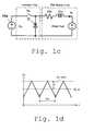
- FIG. 1 cis a schematic of an equivalent circuit for the PWM inverter and the PM motor of FIG. 1 a;
- FIG. 1 dis a current waveform for current ripple in inverter of FIG. 1 a;
- FIG. 2is a graph of current ripple vs. speed for a specific brushless dc motor using a motor control of the prior art
- FIG. 3is an electrical schematic of a dc link inverter using additional inductors to control current ripple
- FIG. 4is an electrical schematic of a dc link inverter using a step down chopper circuit to control current ripple;
- FIG. 5 ais a first electrical schematic representation of a dc link inverter using a multilevel dc voltage source of the present invention
- FIG. 5 bis a second electrical schematic representation of a dc link inverter using a multilevel dc voltage source of the present invention
- FIG. 5 cis an equivalent circuit schematic for the multilevel dc voltage source of FIGS. 5 a and 5 b;
- FIG. 5 dis a graph of trapezoidal back emf and switching conduction periods vs. time for the PWM inverter of FIGS. 5 a and 5 b;
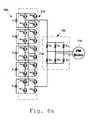
- FIG. 6 ais a more specific example of the multilevel dc voltage source of the present invention.
- FIG. 6 bis a graph of current ripple vs. speed for a conventional inverted of the prior art and for a multilevel dc voltage source inverter of the present invention
- FIG. 6 cis a graph of the bus voltage and phase currents in a conventional PWM inverter of the prior art, showing the current ripple components;
- FIG. 6 dis a graph of the bus voltage and phase currents in a multilevel dc voltage source inverter of the present invention, showing the current ripple components;
- FIG. 7 ais an electrical schematic of a second embodiment of the present invention applied to a switched reluctance motor
- FIG. 7 bis a graph of trapezoidal motor inductance and switching conduction periods vs. time for the PWM inverter of FIG. 7 a;
- FIG. 8 ais an electrical schematic of a third embodiment of the present invention using thyristors in the PWM inverter
- FIG. 8 bis a graph of trapezoidal back emf and switching conduction periods vs. time for the PWM inverter of FIG. 8 a in motoring mode;
- FIG. 8 cis a graph of trapezoidal back emf and switching conduction periods vs. time for the PWM inverter of FIG. 8 a in regenerating mode;
- FIG. 9 ais an electrical schematic of a fourth embodiment of the present invention using a diode clamped multilevel dc voltage source inverter.
- FIG. 9 bis a graph of trapezoidal back emf and switching conduction periods vs. time for the PWM inverter of FIG. 9 a.
- a motor control system 10 for controlling a motor 11which may be a permanent magnet (PM) motor, such as a brushless dc motor or an ac synchronous motor, or in another embodiment described herein, may be a switched reluctance motor.
- PMpermanent magnet
- the permanent magnetsare positioned on the rotor, while the stator has windings for carrying the phase currents.
- the permanent magnetsare typically formed of rare earth magnetic materials such as NdFeB (neodymium-iron-boron).
- NdFeBneodymium-iron-boron
- the waveform of the back EMFcan be either sinusoidal in the case of a permanent magnet synchronous motor or it can be trapezoidal in the case of a brushless dc motor.
- the motor control system 10includes an inverter 15 connected to three phases of the PM motor 11 .
- the inverter 15receives dc power from a dc power source 16 to be described in more detail below.
- a controller 14transmits gating signals to control the firing of semiconductor switches in the inverter 15 for the three phases of the motor 11 .
- the controller 14senses the dc voltage through a dc voltage sensor 17 .
- the controller 14also receives rotor position information from one or more optional position sensors 12 , which may be coupled to the motor output shaft, or positioned near the rotor as described below. Some brushless dc motor controls are classified as sensorless, meaning that they do not utilize position sensors.
- the controller 14also receives current feedback for current sensors 13 in two of the three phase supply lines to the motor. From this current information, the controller can calculate current in the third phase.
- the logic controller 14preferably includes a microelectronic CPU and associated program memory and data memory.
- a programis stored in the program memory and is executed by the CPU to perform a current control loop and other basic control methods well known in the art of motor control.
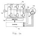
- FIG. 1 aillustrates a typical PWM inverter 15 a of the prior art with six IGBT's (insulated gate bipolar transistors) S 1 -S 6 which switch at appropriate intervals.
- IGBT'sinsulated gate bipolar transistors
- Bypass diodesare connected in parallel to and across the respective six IGBT's S 1 -S 6 to allow transient currents associated with switching the IGBT's to bypass the IGBT's.
- Position sensors 12 asuch as Hall-effect devices are positioned inside the motor to sense rotor position and signals are transmitted to a controller 14 a which calculates speed and generates gate signals through gate driver circuit 19 a to the inverter 15 a .
- Current sensors 13 aprovide signals to the controller 14 a as part of the current loop regulation.
- FIG. 1 bshows the three phase-to-phase back EMFs, a-b, b-c and c-a, which would be developed during operation. Only two of the three phase stator windings are excited at one time. To properly commutate the stator currents, rotor position information is detected with position sensors 12 a as mentioned above. There are six combinations of the stator excitation, S 3 -S 5 , S 1 -S 5 , S 1 -S 6 , S 2 -S 6 , S 2 -S 4 and S 3 -S 4 over a fundamental cycle with each combination lasting for a phase period of ⁇ /3, as depicted in FIG. 1 b .
- the corresponding two switches in each periodcan perform pulse width modulation to regulate the motor current. To reduce current ripple, it is, however, often useful to have one switch doing PWM while keeping the other switch conducting.
- an equivalent circuitis given in FIG. 1 c , where R m and L m are the per-phase resistance and inductance including the mutual inductance between the two conducting windings, respectively, the PWM switch is S W and the diode D is the diode of the other switch in the same phase leg of the PWM switch .
- the commutation overlap during mode transitioncan be ignored for low inductance motors and is therefore not considered in the equivalent circuit.
- V dcinverter dc link voltage
- E bemf — peakpeak phase-to-phase back EMF.
- Equation (1)I m_ripple ⁇ 1 4 ⁇ L m ⁇ f SW ⁇ ( 1 - K bemf ⁇ N V dc ) ⁇ K bemf ⁇ N . ( 2 )
- the maximum current rippleis inversely proportional to the motor inductance and the inverter switching frequency.
- FIG. 4shows another way to reduce current ripple by using a step-down chopper including seventh IGBT S 7 , diodes D 7 and D 8 and inductor L 4 to regulate the dc voltage. This requires the additional inductor, L 4 .
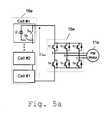
- FIG. 5 ashows the motor control of the present invention, which comprises an incremental dc supply circuit 16 e and a multiphase bridge inverter 15 e .
- the multilevel dc supply circuit 16 eis formed by connecting a number of cells #1, #2, . . . #n in series with each cell having a voltage source Vs controlled by two control switches Sa and Sb.
- the two switches, Sa and Sboperate in a toggle fashion.
- the cell sourceis bypassed with Sa on and Sb off or adds to the dc link voltage by reversing the switches.
- the bridge inverter 15 eis used only to commutate the motor phase currents without doing PWM for current regulation.
- the current regulationis performed by the cell switches.
- k cellsare active but only one of the k number of cells, performs PWM, as shown in FIG. 5 b .
- the required number of active cells, kis determined by E bemf_Peak ⁇ ( max ) V s ⁇ k ⁇ E bemf_Peak ⁇ ( min ) V s + 1. ( 4 )
- controllable speed rangeis defined by ( k - 1 ) ⁇ V s K bemf ⁇ N ⁇ k ⁇ ⁇ V s K bemf . ( 5 )
- the current ripplecan be derived based on the equivalent circuit shown in FIG. 5 c as follows. I m_ripple ⁇ k 2 ⁇ ⁇ V s 4 ⁇ L m ⁇ f SW ⁇ ( 1 - K bemf ⁇ N k ⁇ ⁇ V s ) ⁇ ⁇ ( K bemf ⁇ N k ⁇ ⁇ V s - k - 1 k ) ( 6 )
- FIG. 5 dshows the back EMF and switching conduction periods for the inverter of FIGS. 5 a and 5 b.
- FIG. 6 ashows an embodiment of the invention using power MOSFETS as switches 5 a and 5 b in each cell.
- IGBT'sare used in the inverter 15 f .
- Current and position signalsare transmitted from current sensors 13 f and position sensors 12 f to controller 14 f , which then calculates speed and current commands and transmits commutation signals through IGBT gate drivers 19 f .
- the controller 14 fcontrols the number of voltage cells 16 f which are operated in series by transmitting signals to the cell controller 21 f (Sa 1 -Sa 5 and Sb 1 -Sb 5 ) through MOSFET gate drivers 20 f.
- FIG. 6 bshows curves of the calculated current ripple for this motor 11 f with the conventional inverter 15 a shown in FIG. 1 a , and then with the five-increment dc link inverter 15 f shown in FIG. 6 a .
- the maximum current rippleis reduced by a factor of 5.
- the cell switches 21 fcan be power MOSFETs as shown in FIG. 6 a . This provides an additional option for ripple reduction by switching at a higher frequency, f sw , as shown in equations (3) and (7). It is also useful to rotate the active cells so that the same amount of average power is drawn from each cell source.
- FIG. 6 cshows the current ripple corresponding to the non-incremental dc voltage supply circuit 16 a in FIG. 1 a
- FIG. 6 dshows the current ripple for an incremental dc voltage supply circuit 16 f of FIG. 6 a.
- FIG. 7 ashows an example of the invention for switched reluctance motor drives, in which a five-increment dc supply circuit 16 g and 21 g is employed to power a three-phase reluctance motor 11 g represented by inductors La, Lb and Lc.
- FIG. 7 billustrates operating waveforms and switch gating signals of the inverter 15 g .
- FIG. 8 ashows an alternative configuration of a five-level dc supply circuit 16 h , 21 h employing MOSFETs, Sa 1 -Sa 5 , Sb 1 -Sb 5 , Sc 1 -Sc 5 , Sd 1 -Sd 5 , and an inverter 15 h using thyristors, T 1 -T 6 .
- FIG. 8 billustrates back EMF, bus voltage and switch gating signal waveforms when the lower three voltage cells are active with the middle cell performing PWM and the motor 11 h is in motoring mode.
- the bus voltage Vbusis positive.
- FIG. 8 cillustrates back EMF, bus voltage and switch gating signal waveforms when the lower three cells are active with the middle cell doing PWM but the motor 11 h is in a regeneration mode (the motor functions as a generator as power is fed back from the motor to the power supply). In this mode, the bus voltage Vbus is negative.
- the thyristor bridge inverter 15 his used to commutate the stator current and the current control is accomplished with the selection of active cell number and the pulse width modulation of one of the active cells.
- FIG. 9 ashows an alternative configuration using a diode clamped multilevel dc voltage supply circuit 16 i , 21 i .
- the five capacitors, C 1 -C 5equally divide the dc source voltage, Vdc.
- FIG. 9 billustrates back EMF, bus voltage and switch gating signal waveforms when the lower three capacitors, C 1 -C 3 are active.
Landscapes
- Engineering & Computer Science (AREA)
- Power Engineering (AREA)
- Transportation (AREA)
- Mechanical Engineering (AREA)
- Life Sciences & Earth Sciences (AREA)
- Sustainable Development (AREA)
- Sustainable Energy (AREA)
- Control Of Motors That Do Not Use Commutators (AREA)
Abstract
Description
This invention was made with Government support under Contract No. DE-AC05-00OR22725 to UT-Battelle, LLC, awarded by the U.S. Department of Energy. The Government has certain rights in this invention.
The field of the invention is electronic controls for motors, including brushless DC motors, synchronous ac motors and switched reluctance motors.
Permanent magnet motors are excellent candidates for traction drives in electric/hybrid-electric vehicle applications because of their higher efficiency. Due to a long effective air gap, PM motors tend to have low inductance. Recent design techniques for high power PM motors (rated at several tens of kWs) for electric vehicle and hybrid electrical vehicle propulsion have used an iron-less stator structure to eliminate stator iron loss. This design also reduces stator inductance well below 100 μH. While these types of very low inductance PM motors have the advantages of fast current control response and a linear relationship between current and its developed torque, they impose stringent current regulation demands for the inverter to obtain acceptable current ripple, which should be typically below 5%.
A PM motor can be excited in an ac synchronous mode or brushless dc (BLDC) mode using a dc link inverter to control three-phase switching of current in the windings of a 3-phase motor. The latter excitation provides a low cost drive system, which is well suited for PM motors having a trapezoidal back EMF. There is, however, in the known inverter technology, a problem of unacceptable current ripple with low inductance PM motors.
The maximum current ripple is inversely proportional to the motor inductance and the inverter switching frequency. A standard inverter with the most commonly used IGBT switching devices will produce an unacceptable maximum current ripple of 25% due to the IGBT's switching frequency, which is limited to 20 kHz. This high current ripple not only causes additional motor losses but also requires that the inverter be rated higher to handle the high peak current.
For a given switching frequency, the current ripple can be reduced by adding an external inductor in each phase to increase the inductance. However, inductors rated for high current rating are bulky and this produces a large inductance which undesirably slows current control response. Another method of reducing current ripple uses a step-down chopper to regulate the dc voltage applied to the inverter. This also requires an additional inductor. These approaches have not resulted in a control with the desired features of operation and construction.
In order to reduce current ripple and use permanent magnet (PM) motors having very low inductance, the invention provides a multilevel voltage source for the dc source of a multiple phase bridge inverter. The multilevel voltage source has multiple voltage-controlled cells cascaded to provide the necessary voltage to the motor. To regulate motor current with low ripple, the output voltage of the cells is adjusted through dc voltage level stepping and pulse width modulation (PWM) depending on the amplitude of the motor back electromotive force (EMF).
It is a primary object of the invention to reduce current ripple in a PM motor powered by a dc link inverter to below 5% over the full speed range of the motor.
It is a further object of the invention to provide controls for brushless DC motors, AC synchronous motors and switched reluctance motors having low inductance.
Other objects and advantages of the invention, besides those discussed above, will be apparent to those of ordinary skill in the art from the description of the preferred embodiments which follows. In the description reference is made to the accompanying drawings, which form a part hereof, and which illustrate examples of the invention. Such examples, however are not exhaustive of the various embodiments of the invention, and therefore reference is made to the claims which follow the description for determining the scope of the invention.
FIG. 1 is a block diagram of a motor control of the present invention connected to control a brushless dc motor;
FIG. 1ais a detail schematic of PWM inverter of the prior art;
FIG. 1bis a graph of trapezoidal back emf and switching conduction periods vs. time for the PWM inverter of FIG. 1a;
FIG. 1cis a schematic of an equivalent circuit for the PWM inverter and the PM motor of FIG. 1a;
FIG. 1dis a current waveform for current ripple in inverter of FIG. 1a;
FIG. 2 is a graph of current ripple vs. speed for a specific brushless dc motor using a motor control of the prior art;
FIG. 3 is an electrical schematic of a dc link inverter using additional inductors to control current ripple;
FIG. 4 is an electrical schematic of a dc link inverter using a step down chopper circuit to control current ripple;
FIG. 5ais a first electrical schematic representation of a dc link inverter using a multilevel dc voltage source of the present invention;
FIG. 5bis a second electrical schematic representation of a dc link inverter using a multilevel dc voltage source of the present invention;
FIG. 5cis an equivalent circuit schematic for the multilevel dc voltage source of FIGS. 5aand5b;
FIG. 5dis a graph of trapezoidal back emf and switching conduction periods vs. time for the PWM inverter of FIGS. 5aand5b;
FIG. 6ais a more specific example of the multilevel dc voltage source of the present invention;
FIG. 6bis a graph of current ripple vs. speed for a conventional inverted of the prior art and for a multilevel dc voltage source inverter of the present invention;
FIG. 6cis a graph of the bus voltage and phase currents in a conventional PWM inverter of the prior art, showing the current ripple components;
FIG. 6dis a graph of the bus voltage and phase currents in a multilevel dc voltage source inverter of the present invention, showing the current ripple components;
FIG. 7ais an electrical schematic of a second embodiment of the present invention applied to a switched reluctance motor;
FIG. 7bis a graph of trapezoidal motor inductance and switching conduction periods vs. time for the PWM inverter of FIG. 7a;
FIG. 8ais an electrical schematic of a third embodiment of the present invention using thyristors in the PWM inverter;
FIG. 8bis a graph of trapezoidal back emf and switching conduction periods vs. time for the PWM inverter of FIG. 8ain motoring mode;
FIG. 8cis a graph of trapezoidal back emf and switching conduction periods vs. time for the PWM inverter of FIG. 8ain regenerating mode;
FIG. 9ais an electrical schematic of a fourth embodiment of the present invention using a diode clamped multilevel dc voltage source inverter; and
FIG. 9bis a graph of trapezoidal back emf and switching conduction periods vs. time for the PWM inverter of FIG. 9a.
Referring to FIG. 1, the present invention is embodied in amotor control system 10 for controlling amotor 11, which may be a permanent magnet (PM) motor, such as a brushless dc motor or an ac synchronous motor, or in another embodiment described herein, may be a switched reluctance motor. In permanent magnet (PM) motors, the permanent magnets are positioned on the rotor, while the stator has windings for carrying the phase currents. The permanent magnets are typically formed of rare earth magnetic materials such as NdFeB (neodymium-iron-boron). When the rotor of these motors rotates, the rotating magnets induce a back EMF voltage in the stator. The magnitude of the back EMF increases with the speed of the rotor. The waveform of the back EMF can be either sinusoidal in the case of a permanent magnet synchronous motor or it can be trapezoidal in the case of a brushless dc motor.
As further seen in FIG. 1, themotor control system 10 includes aninverter 15 connected to three phases of thePM motor 11. Theinverter 15 receives dc power from adc power source 16 to be described in more detail below. Acontroller 14 transmits gating signals to control the firing of semiconductor switches in theinverter 15 for the three phases of themotor 11. Thecontroller 14 senses the dc voltage through adc voltage sensor 17. Thecontroller 14 also receives rotor position information from one or moreoptional position sensors 12, which may be coupled to the motor output shaft, or positioned near the rotor as described below. Some brushless dc motor controls are classified as sensorless, meaning that they do not utilize position sensors. Thecontroller 14 also receives current feedback forcurrent sensors 13 in two of the three phase supply lines to the motor. From this current information, the controller can calculate current in the third phase.
Thelogic controller 14 preferably includes a microelectronic CPU and associated program memory and data memory. A program is stored in the program memory and is executed by the CPU to perform a current control loop and other basic control methods well known in the art of motor control.
Motor current ripple forinverter 15aandbrushless PM motor 11a(FIG. 1a) can be analyzed by an equivalent circuit (FIG. 1c). FIG. 1aillustrates atypical PWM inverter 15aof the prior art with six IGBT's (insulated gate bipolar transistors) S1-S6 which switch at appropriate intervals. Bypass diodes are connected in parallel to and across the respective six IGBT's S1-S6 to allow transient currents associated with switching the IGBT's to bypass the IGBT's.Position sensors 12asuch as Hall-effect devices are positioned inside the motor to sense rotor position and signals are transmitted to acontroller 14awhich calculates speed and generates gate signals throughgate driver circuit 19ato theinverter 15a.Current sensors 13aprovide signals to thecontroller 14aas part of the current loop regulation.
FIG. 1bshows the three phase-to-phase back EMFs, a-b, b-c and c-a, which would be developed during operation. Only two of the three phase stator windings are excited at one time. To properly commutate the stator currents, rotor position information is detected withposition sensors 12aas mentioned above. There are six combinations of the stator excitation, S3-S5, S1-S5, S1-S6, S2-S6, S2-S4 and S3-S4 over a fundamental cycle with each combination lasting for a phase period of π/3, as depicted in FIG. 1b. The corresponding two switches in each period can perform pulse width modulation to regulate the motor current. To reduce current ripple, it is, however, often useful to have one switch doing PWM while keeping the other switch conducting. For such a PWM scheme, an equivalent circuit is given in FIG. 1c, where Rmand Lmare the per-phase resistance and inductance including the mutual inductance between the two conducting windings, respectively, the PWM switch is SWand the diode D is the diode of the other switch in the same phase leg of the PWM switch . The commutation overlap during mode transition can be ignored for low inductance motors and is therefore not considered in the equivalent circuit.
Ignoring the stator coil resistance, current ripple, defined as the peak deviation from the average current as shown in FIG. 1d, at steady state and continuous conduction mode can be determined by the following equation.

where
fsw: inverter switching frequency, fsw=1/Tsw
Vdc: inverter dc link voltage,
Ebemf— peak: peak phase-to-phase back EMF.
Assuming the back EMF is linearly related to the motor speed, N, by Ebemf— peak=KbemfN, where Kbemfis a constant determined by the motor, equation (1) can be rewritten as


The maximum current ripple is inversely proportional to the motor inductance and the inverter switching frequency. A plot of current ripple as a percentage of the rated current vs. speed is shown in FIG. 2 for a 30 kW BLPM motor having a rated current of 110 amps and a phase inductance of Lm=37.5 μH with the inverter switching at 20 kHz and Vdc=325V. It shows that a standard inverter with the most commonly used IGBT switching devices will produce an unacceptable maximum current ripple of 25% due to the IGBT's limited switching frequency, which is limited to 20 kHz. This high ripple current percentage Iripple(peak)[%] not only causes additional motor losses but also requires that the inverter be rated higher than otherwise would be to handle high peak current. For a given switching frequency, one can reduce the current ripple by adding external inductors, L1, L2, and L3, to increase the inductance as shown in FIG.3. However, inductors rated for high current rating are bulky and a large inductance undesirably slows current control response. FIG. 4 shows another way to reduce current ripple by using a step-down chopper including seventh IGBT S7, diodes D7 and D8 and inductor L4to regulate the dc voltage. This requires the additional inductor, L4.
FIG. 5ashows the motor control of the present invention, which comprises an incrementaldc supply circuit 16eand amultiphase bridge inverter 15e. The multileveldc supply circuit 16eis formed by connecting a number ofcells # 1, #2, . . . #n in series with each cell having a voltage source Vs controlled by two control switches Sa and Sb. The two switches, Sa and Sb, operate in a toggle fashion. The cell source is bypassed with Sa on and Sb off or adds to the dc link voltage by reversing the switches.
To control aPM motor 11ein BLDC mode, thebridge inverter 15eis used only to commutate the motor phase currents without doing PWM for current regulation. The current regulation is performed by the cell switches. For a given range of back EMF defined by its minimum Ebemf— Peak(min) and maximum Ebemf— Peak(max), k cells are active but only one of the k number of cells, performs PWM, as shown in FIG. 5b. The required number of active cells, k, is determined by

where Vs is the source voltage of each cell. Since n cells cover the full voltage range, and with 1<=k<=n, the number of active cells increases with motor speed.


From equations (3) and (7), the maximum current ripple is reduced by a factor of Vdc/Vs, i.e. the number of cells. FIG. 5dshows the back EMF and switching conduction periods for the inverter of FIGS. 5aand5b.
FIG. 6ashows an embodiment of the invention using power MOSFETS as switches5aand5bin each cell. IGBT's are used in theinverter 15f. Current and position signals are transmitted fromcurrent sensors 13fandposition sensors 12ftocontroller 14f, which then calculates speed and current commands and transmits commutation signals throughIGBT gate drivers 19f. Thecontroller 14fcontrols the number ofvoltage cells 16fwhich are operated in series by transmitting signals to thecell controller 21f(Sa1-Sa5 and Sb1-Sb5) throughMOSFET gate drivers 20f.
FIG. 6bshows curves of the calculated current ripple for thismotor 11fwith theconventional inverter 15ashown in FIG. 1a, and then with the five-incrementdc link inverter 15fshown in FIG. 6a. The maximum current ripple is reduced by a factor of 5. It is noted that since the cell voltage is low, the cell switches21fcan be power MOSFETs as shown in FIG. 6a. This provides an additional option for ripple reduction by switching at a higher frequency, fsw, as shown in equations (3) and (7). It is also useful to rotate the active cells so that the same amount of average power is drawn from each cell source. FIG. 6cshows the current ripple corresponding to the non-incremental dcvoltage supply circuit 16ain FIG. 1aand FIG. 6dshows the current ripple for an incremental dcvoltage supply circuit 16fof FIG. 6a.
While current ripple is best reduced when the voltage cells provide equal dc voltage, the invention would also reduce ripple in some measure where the voltage was divided into unequal increments.
The concept can also be applied to switched reluctance motor drives. FIG. 7ashows an example of the invention for switched reluctance motor drives, in which a five-incrementdc supply circuit phase reluctance motor 11grepresented by inductors La, Lb and Lc. FIG. 7billustrates operating waveforms and switch gating signals of theinverter 15g. Switches S1-S6 are used to commutate the stator currents according to the rotor position, θ and motor current regulation is accomplished by selecting an adequate number, k (where k=1, 2, 3, 4 or 5), of active cells according to the motor speed and by having one of the active cells performing pulse width modulation. The remaining inactive cells are bypassed by turning on switches Sa (k+1 to 5) while maintaining their counterparts Sb (k+1 to 5) in an off condition.
FIG. 8ashows an alternative configuration of a five-leveldc supply circuit inverter 15husing thyristors, T1-T6. FIG. 8billustrates back EMF, bus voltage and switch gating signal waveforms when the lower three voltage cells are active with the middle cell performing PWM and themotor 11his in motoring mode. The bus voltage Vbus is positive. FIG. 8cillustrates back EMF, bus voltage and switch gating signal waveforms when the lower three cells are active with the middle cell doing PWM but themotor 11his in a regeneration mode (the motor functions as a generator as power is fed back from the motor to the power supply). In this mode, the bus voltage Vbus is negative. Thethyristor bridge inverter 15his used to commutate the stator current and the current control is accomplished with the selection of active cell number and the pulse width modulation of one of the active cells.
FIG. 9ashows an alternative configuration using a diode clamped multilevel dcvoltage supply circuit
This has been a description of the preferred embodiments of the invention. The present invention is intended to encompass additional embodiments including modifications to the details described above which would nevertheless come within the scope of the following claims.
Claims (19)
1. A circuit for controlling a three-phase machine having a stator with stator windings and a rotor, the circuit comprising:
a plurality of commutation switches which are connected to supply current to the stator windings;
a plurality of dc source connections for receiving a plurality of incremental dc voltages and for applying a selected sum of said incremental dc voltages to said plurality of commutation switches to provide a base dc voltage, while controlling one of the incremental dc voltages to provide a varying pulsed signal to said commutation switches relative to said base dc voltage;
at least one sensor for sensing a parameter of the motor from which a speed and rotor position of the motor can be determined; and
a controller responsive to said sensor for determining the speed and rotor position of the motor, said controller being connected for control of said dc source connections to change base dc voltage in response to changes in speed of the motor without increasing current ripple in the stator windings substantially above a current ripple resulting from applying the varying pulsed signal derived from one of the incremental dc voltages to said commutation switches, said controller being connected also for control of said commutation switches to sequentially excite the stator windings of said motor.
2. The circuit ofclaim 1 , wherein said commutation switches are semiconductor devices whose turn-on and turn-off can be controlled through a gating terminal, and a plurality of diodes, each in parallel connection to a respective one of the plurality of said commutation switches for allowing conduction in a reverse direction to bypass each respective primary commutation switch.
3. The circuit ofclaim 2 , wherein said dc source connections include a plurality of control switches for controlling connection to a plurality of dc sources.
4. The circuit ofclaim 3 , wherein at least one of the dc source connections includes at least two control switches, comprising a first control switch for applying the incremental dc voltage to said commutation switches and a second control switch for bypassing the incremental dc voltage and wherein the first and second control switches perform pulse width modulation in response to signals from the controller.
5. The circuit ofclaim 4 , wherein said dc source connection also includes a capacitor for storing an incremental voltage derived from an external voltage source and a diode for clamping the voltage across each of said first and second control switches to said incremental voltage.
6. The circuit ofclaim 4 , wherein said commutation switches are adapted for connection to a stator of a PM motor.
7. The circuit ofclaim 4 , wherein said commutation switches are adapted for connection to a stator of a switched reluctance motor.
8. The circuit ofclaim 1 , wherein said commutation switches are semiconductor devices in which turn-on can be controlled but in which turn-off cannot be controlled through a gating terminal.
9. The circuit ofclaim 8 , wherein said dc source connections include a plurality of control switches for controlling connection to a plurality of dc sources.
10. The circuit ofclaim 8 , wherein said dc source connection for each external dc voltage source includes a bridge network of four control switches for operating alternatively in the motoring mode or in the regenerating mode.
11. The circuit ofclaim 1 , wherein the incremental dc voltages are not all equal.
12. A method of controlling a three-phase machine having a stator with stator windings and a rotor, the circuit comprising:
turning on in sequence a plurality of primary commutation switches connected to supply current to the stator windings;
receiving a plurality of incremental dc voltages and selecting a sum of the incremental dc voltages to apply to said plurality of commutation switches as a base dc voltage;
varying one of the incremental dc voltages to apply a varying pulsed signal to the commutation switches in relation to said base dc voltage;
sensing a parameter of the motor from which a speed of the motor can be determined;
determining a speed of the motor, and wherein the base dc voltage is selected in response to changes in speed of the motor without increasing current ripple in the stator windings substantially above a current ripple resulting from varying said one of the incremental dc voltages to apply the varying pulsed signal to said commutation switches; and
determining a rotor position of the motor, and turning on and off said commutation switches to sequentially excite the stator windings of said motor.
13. The method ofclaim 12 , further comprising dividing a dc voltage from an external dc voltage source into incremental dc voltages.
14. The method ofclaim 12 , current from said commutation switches is supplied to a stator of a PM motor.
15. The method ofclaim 12 , current from said commutation switches is supplied to a switched reluctance motor.
16. The method ofclaim 12 , further comprising controlling signals applied to the primary commutation switches from said motor to direct the commutation sequences for operating in the motoring mode or for operating in the regenerating mode.
17. The method ofclaim 12 , wherein the incremental dc voltages are not all equal.
18. A circuit for controlling a three-phase machine having a stator with stator windings and a rotor, the circuit comprising:
a plurality of commutation switches which are connected to supply current to the stator windings;
a plurality of voltage-controlled cells in cascade arrangement for applying a resulting dc voltage to said plurality of commutation switches, said resulting dc voltage comprising at least one of a plurality of incremental dc voltages corresponding to said plurality of voltage-controlled cells, at least one of said cells also providing a varying pulsed signal to said commutation switches;
at least one sensor for sensing a parameter of the motor from which a speed and rotor position of the motor can be determined; and
a controller responsive to said sensor for determining the speed and rotor position of the motor, said controller being connected for control of said dc source connections to change said resulting dc voltage in response to changes in speed of the motor without increasing current ripple in the stator windings substantially above a current ripple resulting from the varying pulsed signal supplied from said one of the voltage-controlled cells to said commutation switches.
19. The circuit ofclaim 18 , wherein at least one of the voltage-controlled cells includes at least two control switches, comprising a first control switch for applying the incremental dc voltage to said commutation switches and a second control switch for bypassing the incremental dc voltage and wherein the two control switches perform pulse width modulation in response to signals from the controller.
Priority Applications (1)
| Application Number | Priority Date | Filing Date | Title |
|---|---|---|---|
| US09/853,133US6577087B2 (en) | 2001-05-10 | 2001-05-10 | Multilevel DC link inverter |
Applications Claiming Priority (1)
| Application Number | Priority Date | Filing Date | Title |
|---|---|---|---|
| US09/853,133US6577087B2 (en) | 2001-05-10 | 2001-05-10 | Multilevel DC link inverter |
Publications (2)
| Publication Number | Publication Date |
|---|---|
| US20020175644A1 US20020175644A1 (en) | 2002-11-28 |
| US6577087B2true US6577087B2 (en) | 2003-06-10 |
Family
ID=25315156
Family Applications (1)
| Application Number | Title | Priority Date | Filing Date |
|---|---|---|---|
| US09/853,133Expired - Fee RelatedUS6577087B2 (en) | 2001-05-10 | 2001-05-10 | Multilevel DC link inverter |
Country Status (1)
| Country | Link |
|---|---|
| US (1) | US6577087B2 (en) |
Cited By (30)
| Publication number | Priority date | Publication date | Assignee | Title |
|---|---|---|---|---|
| US20020105335A1 (en)* | 1999-09-16 | 2002-08-08 | Mir Sayeed A. | Current determination in a permanent magnet electric machine |
| US20030006739A1 (en)* | 2000-06-06 | 2003-01-09 | Gerhard Koelle | Method for improving the efficiency of an electrical machine |
| US20030210009A1 (en)* | 2002-05-10 | 2003-11-13 | Analog Devices, Inc. | Pulse width modulated drive system for electronically commutated motors |
| US20040067049A1 (en)* | 2002-10-08 | 2004-04-08 | Woodward Arthur E. | PSC motor system for use in HVAC applications with field adjustment and fail-safe capabilities |
| US20050077862A1 (en)* | 2002-07-22 | 2005-04-14 | Switched Reluctance Drives Limited | Control of a switched reluctance drive |
| US20050127853A1 (en)* | 2003-12-12 | 2005-06-16 | Gui-Jia Su | Multi-level dc bus inverter for providing sinusoidal and pwm electrical machine voltages |
| US6938713B1 (en)* | 1999-09-20 | 2005-09-06 | Hitachi, Ltd. | Dynamotor of hybrid vehicle, and method of control thereof |
| US20050231152A1 (en)* | 2004-04-19 | 2005-10-20 | Brian Welchko | Inverter for electric and hybrid powered vehicles and associated system and method |
| US20050254801A1 (en)* | 2004-05-12 | 2005-11-17 | Walter Koellner | Method for powering mining equipment |
| US20060061320A1 (en)* | 2004-09-21 | 2006-03-23 | Ma Jack D | Power converter controlling apparatus and method providing ride through capability during power interruption in a motor drive system |
| US20060113954A1 (en)* | 2004-11-30 | 2006-06-01 | Honeywell International Inc. | Advanced current control method and apparatus for a motor drive system |
| US20060267527A1 (en)* | 2005-05-26 | 2006-11-30 | Khopkar Rahul V | System, apparatus and method for driving permanent magnet electrical machine |
| US20070013325A1 (en)* | 2005-07-13 | 2007-01-18 | Mitsuyuki Kiuchi | Motor drive unit |
| US20070222403A1 (en)* | 2006-03-23 | 2007-09-27 | Delphi Technologies, Inc. | Method for producing voltage waveforms in a PWM motor controller of a PM DC brushless motor |
| US20080050099A1 (en)* | 2006-08-28 | 2008-02-28 | Zhongshan Broad-Ocean Motor Co., Ltd. | Universal brushless dc motor |
| US20080247204A1 (en)* | 2005-09-02 | 2008-10-09 | Vdo Automotive Ag | Regulator Device for a Three-Phase Ac Machine |
| CN101917108A (en)* | 2010-08-26 | 2010-12-15 | 刘大椿 | Storage battery-powered multiphase permanent magnet brushless DC motor |
| US20120074885A1 (en)* | 2009-05-27 | 2012-03-29 | Sanden Corporation | Motor control device |
| DE102011006762A1 (en) | 2011-04-05 | 2012-10-11 | Robert Bosch Gmbh | Battery direct converter in ring configuration |
| DE102011006761A1 (en) | 2011-04-05 | 2012-10-11 | Robert Bosch Gmbh | Switching matrix of switching system, has switching devices that are arranged to switch supply terminals with respect to output ports in response to control signals to form series/parallel/bridging circuit with power sources |
| US8536734B2 (en) | 2010-04-14 | 2013-09-17 | East Coast Research And Development, Llc | Apparatus for inverting DC voltage to AC voltage |
| US20140062356A1 (en)* | 2012-09-06 | 2014-03-06 | Robert Bosch Gmbh | Inverter for driving an electrical load and method for operating an interter |
| US8760105B2 (en) | 2010-11-30 | 2014-06-24 | Ut-Battelle, Llc | Electric machine and current source inverter drive system |
| CN105186965A (en)* | 2014-05-26 | 2015-12-23 | 日本电产三协株式会社 | Motor control device and motor control method |
| WO2016029816A1 (en)* | 2014-08-27 | 2016-03-03 | 中国矿业大学 | Four-phase switched reluctance motor torque ripple three-level suppression method |
| US9306407B2 (en) | 2011-12-22 | 2016-04-05 | Robert Bosch Gmbh | Battery system and method |
| US9318974B2 (en) | 2014-03-26 | 2016-04-19 | Solaredge Technologies Ltd. | Multi-level inverter with flying capacitor topology |
| US20170005562A1 (en)* | 2013-12-18 | 2017-01-05 | Otis Elevator Company | Bus capacitor bank configuration for a multi-level regenerative drive |
| US20170222590A1 (en)* | 2014-08-27 | 2017-08-03 | China University Of Mining And Technology | Three-phase switched reluctance motor torque ripple two-level suppression method |
| US9941813B2 (en) | 2013-03-14 | 2018-04-10 | Solaredge Technologies Ltd. | High frequency multi-level inverter |
Families Citing this family (27)
| Publication number | Priority date | Publication date | Assignee | Title |
|---|---|---|---|---|
| US20040251860A1 (en)* | 2003-01-09 | 2004-12-16 | Mehrdad Ehsani | Advanced sensorless drive technique for brushless DC motors |
| US6836087B2 (en)* | 2003-01-29 | 2004-12-28 | Wavecrest Laboratories, Llc | Multiphase motor voltage control for phase windings of different wire gauges and winding turns |
| CA2510646C (en)* | 2003-01-29 | 2007-06-12 | Alexander A. Gladkov | Multiphase motor voltage control for phase windings of different wire gauges and winding turns |
| US20060066274A1 (en)* | 2004-09-30 | 2006-03-30 | Valeo Electrical Systems, Inc. | Overmodulation of electric motor in power steering system |
| US7932693B2 (en)* | 2005-07-07 | 2011-04-26 | Eaton Corporation | System and method of controlling power to a non-motor load |
| EP2061132B1 (en)* | 2006-08-23 | 2023-07-19 | Kabushiki Kaisha Toshiba | Permanent magnetic type electric motor |
| WO2008142649A1 (en)* | 2007-05-24 | 2008-11-27 | Philips Intellectual Property & Standards Gmbh | Power supply comprising a plurality of current controlled voltage sources that can be switched on and off |
| FR2919971B1 (en)* | 2007-08-06 | 2009-10-16 | Leroy Somer Moteurs | ELECTRIC GENERATOR AND INSTALLATION COMPRISING A LIGHTING TOWER SUPPLIED BY SUCH A GENERATOR |
| US7940020B2 (en)* | 2007-11-16 | 2011-05-10 | The Bergquist Torrington Company | Brushless DC motor with reduced current ripple |
| DE102010041499A1 (en)* | 2010-09-28 | 2012-03-29 | Robert Bosch Gmbh | Sensor device with current limiter unit |
| DE102011003778A1 (en) | 2011-02-08 | 2012-08-09 | Robert Bosch Gmbh | A method of operating a control system for an electric machine and system for controlling an electric machine |
| ES2663897T3 (en)* | 2011-04-01 | 2018-04-17 | Siemens Aktiengesellschaft | Method to produce an output voltage in a modular multilevel converter and method to execute the method |
| DE102011075421A1 (en)* | 2011-05-06 | 2012-11-08 | Sb Limotive Company Ltd. | Battery with at least one battery module string |
| CN103066633B (en)* | 2011-10-18 | 2015-11-18 | 丁景信 | Power management system |
| DE102011087028A1 (en)* | 2011-11-24 | 2013-05-29 | Sb Limotive Company Ltd. | Battery module string for driving a DC motor |
| DE102012202173B4 (en)* | 2012-02-14 | 2013-08-29 | Siemens Aktiengesellschaft | Method for operating a multiphase, modular multilevel converter |
| FR2994899B1 (en)* | 2012-08-29 | 2014-09-12 | Renault Sa | METHOD FOR CONTROLLING AN ELECTRIC MACHINE LIMITING ENERGY LOSSES |
| CN102843077B (en)* | 2012-09-18 | 2015-11-18 | 东南大学 | A kind of switch reluctance motor control method based on synchronous rectification |
| CN103731127B (en)* | 2012-10-16 | 2016-12-21 | 通用电气公司 | Circuit for the electrical switch that Synchronization Control is connected in series |
| US9099954B2 (en)* | 2013-07-25 | 2015-08-04 | Caterpillar Inc. | Enforced zero voltage loop |
| DE102014214984A1 (en) | 2014-07-30 | 2016-02-04 | Robert Bosch Gmbh | Short-circuit protection device |
| DE102014215070A1 (en) | 2014-07-31 | 2016-02-04 | Robert Bosch Gmbh | Method for operating a battery system and motor vehicle |
| DE102015205691A1 (en) | 2015-03-30 | 2016-10-06 | Siemens Aktiengesellschaft | Method for reducing the noise of an electric motor |
| US10277084B1 (en) | 2016-10-19 | 2019-04-30 | Waymo Llc | Planar rotary transformer |
| CN106712593A (en)* | 2017-02-20 | 2017-05-24 | 天津工业大学 | Switched reluctance motor four-level power circuit |
| EP3999376A4 (en)* | 2019-08-16 | 2022-11-16 | Magna International Inc | CHARGER FOR ELECTRICAL CONNECTORS |
| IL275886A (en)* | 2020-07-06 | 2022-02-01 | Irp Nexus Group Ltd | Direct drive system for brushless dc (bldc) motor |
Citations (3)
| Publication number | Priority date | Publication date | Assignee | Title |
|---|---|---|---|---|
| US5929590A (en)* | 1997-01-07 | 1999-07-27 | Emerson Electric Co. | Method and apparatus for implementing sensorless control of a switched reluctance machine |
| US6051942A (en)* | 1996-04-12 | 2000-04-18 | Emerson Electric Motor Co. | Method and apparatus for controlling a switched reluctance machine |
| US6060859A (en)* | 1997-09-30 | 2000-05-09 | Kabushiki Kaisha Toshiba | Motor driver having a booster circuit and an inverter both controlled by pulse width modulation |
- 2001
- 2001-05-10USUS09/853,133patent/US6577087B2/ennot_activeExpired - Fee Related
Patent Citations (3)
| Publication number | Priority date | Publication date | Assignee | Title |
|---|---|---|---|---|
| US6051942A (en)* | 1996-04-12 | 2000-04-18 | Emerson Electric Motor Co. | Method and apparatus for controlling a switched reluctance machine |
| US5929590A (en)* | 1997-01-07 | 1999-07-27 | Emerson Electric Co. | Method and apparatus for implementing sensorless control of a switched reluctance machine |
| US6060859A (en)* | 1997-09-30 | 2000-05-09 | Kabushiki Kaisha Toshiba | Motor driver having a booster circuit and an inverter both controlled by pulse width modulation |
Cited By (62)
| Publication number | Priority date | Publication date | Assignee | Title |
|---|---|---|---|---|
| US7042227B2 (en)* | 1999-09-16 | 2006-05-09 | Delphi Technologies, Inc. | Current determination in a permanent magnet electric machine |
| US20020105335A1 (en)* | 1999-09-16 | 2002-08-08 | Mir Sayeed A. | Current determination in a permanent magnet electric machine |
| US6938713B1 (en)* | 1999-09-20 | 2005-09-06 | Hitachi, Ltd. | Dynamotor of hybrid vehicle, and method of control thereof |
| US20030006739A1 (en)* | 2000-06-06 | 2003-01-09 | Gerhard Koelle | Method for improving the efficiency of an electrical machine |
| US6744240B2 (en)* | 2000-06-06 | 2004-06-01 | Robert Bosch Gmbh | Method for improving the efficiency of an electrical machine |
| US20030210009A1 (en)* | 2002-05-10 | 2003-11-13 | Analog Devices, Inc. | Pulse width modulated drive system for electronically commutated motors |
| US6972533B2 (en)* | 2002-07-22 | 2005-12-06 | Switched Reluctance Drives Limited | Control of a switched reluctance drive |
| US20050077862A1 (en)* | 2002-07-22 | 2005-04-14 | Switched Reluctance Drives Limited | Control of a switched reluctance drive |
| US20040067049A1 (en)* | 2002-10-08 | 2004-04-08 | Woodward Arthur E. | PSC motor system for use in HVAC applications with field adjustment and fail-safe capabilities |
| US20050127853A1 (en)* | 2003-12-12 | 2005-06-16 | Gui-Jia Su | Multi-level dc bus inverter for providing sinusoidal and pwm electrical machine voltages |
| US6969967B2 (en) | 2003-12-12 | 2005-11-29 | Ut-Battelle Llc | Multi-level dc bus inverter for providing sinusoidal and PWM electrical machine voltages |
| US20050231152A1 (en)* | 2004-04-19 | 2005-10-20 | Brian Welchko | Inverter for electric and hybrid powered vehicles and associated system and method |
| US7057371B2 (en) | 2004-04-19 | 2006-06-06 | General Motors Corporation | Inverter for electric and hybrid powered vehicles and associated system and method |
| US20050254801A1 (en)* | 2004-05-12 | 2005-11-17 | Walter Koellner | Method for powering mining equipment |
| US7398012B2 (en)* | 2004-05-12 | 2008-07-08 | Siemens Energy & Automation, Inc. | Method for powering mining equipment |
| US7116067B2 (en) | 2004-09-21 | 2006-10-03 | Honeywell International Inc. | Power converter controlling apparatus and method providing ride through capability during power interruption in a motor drive system |
| US20060061320A1 (en)* | 2004-09-21 | 2006-03-23 | Ma Jack D | Power converter controlling apparatus and method providing ride through capability during power interruption in a motor drive system |
| US7348756B2 (en) | 2004-11-30 | 2008-03-25 | Honeywell International Inc. | Advanced current control method and apparatus for a motor drive system |
| US20060113954A1 (en)* | 2004-11-30 | 2006-06-01 | Honeywell International Inc. | Advanced current control method and apparatus for a motor drive system |
| US20060267527A1 (en)* | 2005-05-26 | 2006-11-30 | Khopkar Rahul V | System, apparatus and method for driving permanent magnet electrical machine |
| US7466086B2 (en)* | 2005-07-13 | 2008-12-16 | Panasonic Corporation | Motor drive unit |
| US20070013325A1 (en)* | 2005-07-13 | 2007-01-18 | Mitsuyuki Kiuchi | Motor drive unit |
| US20080247204A1 (en)* | 2005-09-02 | 2008-10-09 | Vdo Automotive Ag | Regulator Device for a Three-Phase Ac Machine |
| US20070222403A1 (en)* | 2006-03-23 | 2007-09-27 | Delphi Technologies, Inc. | Method for producing voltage waveforms in a PWM motor controller of a PM DC brushless motor |
| US7402969B2 (en)* | 2006-03-23 | 2008-07-22 | Delphi Technologies, Inc | Method for producing voltage waveforms in a PWM motor controller of a PM DC brushless motor |
| US20080050099A1 (en)* | 2006-08-28 | 2008-02-28 | Zhongshan Broad-Ocean Motor Co., Ltd. | Universal brushless dc motor |
| US7671551B2 (en)* | 2006-08-28 | 2010-03-02 | Zhongshan Broad-Ocean Motor Co., Ltd. | Universal brushless DC motor |
| US20120074885A1 (en)* | 2009-05-27 | 2012-03-29 | Sanden Corporation | Motor control device |
| US9024555B2 (en)* | 2009-05-27 | 2015-05-05 | Sanden Corporation | Motor control device |
| US8536734B2 (en) | 2010-04-14 | 2013-09-17 | East Coast Research And Development, Llc | Apparatus for inverting DC voltage to AC voltage |
| CN101917108A (en)* | 2010-08-26 | 2010-12-15 | 刘大椿 | Storage battery-powered multiphase permanent magnet brushless DC motor |
| CN101917108B (en)* | 2010-08-26 | 2012-09-05 | 刘大椿 | Storage battery-powered multiphase permanent magnet brushless DC motor |
| US8760105B2 (en) | 2010-11-30 | 2014-06-24 | Ut-Battelle, Llc | Electric machine and current source inverter drive system |
| DE102011006762A1 (en) | 2011-04-05 | 2012-10-11 | Robert Bosch Gmbh | Battery direct converter in ring configuration |
| WO2012136395A1 (en) | 2011-04-05 | 2012-10-11 | Robert Bosch Gmbh | Battery cycloconverter in a ring configuration |
| DE102011006761A1 (en) | 2011-04-05 | 2012-10-11 | Robert Bosch Gmbh | Switching matrix of switching system, has switching devices that are arranged to switch supply terminals with respect to output ports in response to control signals to form series/parallel/bridging circuit with power sources |
| US9306407B2 (en) | 2011-12-22 | 2016-04-05 | Robert Bosch Gmbh | Battery system and method |
| US20140062356A1 (en)* | 2012-09-06 | 2014-03-06 | Robert Bosch Gmbh | Inverter for driving an electrical load and method for operating an interter |
| US9941813B2 (en) | 2013-03-14 | 2018-04-10 | Solaredge Technologies Ltd. | High frequency multi-level inverter |
| US12119758B2 (en) | 2013-03-14 | 2024-10-15 | Solaredge Technologies Ltd. | High frequency multi-level inverter |
| US11742777B2 (en) | 2013-03-14 | 2023-08-29 | Solaredge Technologies Ltd. | High frequency multi-level inverter |
| US11545912B2 (en) | 2013-03-14 | 2023-01-03 | Solaredge Technologies Ltd. | High frequency multi-level inverter |
| US20170005562A1 (en)* | 2013-12-18 | 2017-01-05 | Otis Elevator Company | Bus capacitor bank configuration for a multi-level regenerative drive |
| US10008917B2 (en)* | 2013-12-18 | 2018-06-26 | Otis Elevator Company | Bus capacitor bank configuration for a multi-level regenerative drive |
| US10153685B2 (en) | 2014-03-26 | 2018-12-11 | Solaredge Technologies Ltd. | Power ripple compensation |
| US10886832B2 (en) | 2014-03-26 | 2021-01-05 | Solaredge Technologies Ltd. | Multi-level inverter |
| US12136890B2 (en) | 2014-03-26 | 2024-11-05 | Solaredge Technologies Ltd. | Multi-level inverter |
| US11855552B2 (en) | 2014-03-26 | 2023-12-26 | Solaredge Technologies Ltd. | Multi-level inverter |
| US11632058B2 (en) | 2014-03-26 | 2023-04-18 | Solaredge Technologies Ltd. | Multi-level inverter |
| US10404154B2 (en) | 2014-03-26 | 2019-09-03 | Solaredge Technologies Ltd | Multi-level inverter with flying capacitor topology |
| US10680505B2 (en) | 2014-03-26 | 2020-06-09 | Solaredge Technologies Ltd. | Multi-level inverter |
| US10680506B2 (en) | 2014-03-26 | 2020-06-09 | Solaredge Technologies Ltd. | Multi-level inverter |
| US10700588B2 (en) | 2014-03-26 | 2020-06-30 | Solaredge Technologies Ltd. | Multi-level inverter |
| US9318974B2 (en) | 2014-03-26 | 2016-04-19 | Solaredge Technologies Ltd. | Multi-level inverter with flying capacitor topology |
| US10886831B2 (en) | 2014-03-26 | 2021-01-05 | Solaredge Technologies Ltd. | Multi-level inverter |
| US11296590B2 (en) | 2014-03-26 | 2022-04-05 | Solaredge Technologies Ltd. | Multi-level inverter |
| CN105186965A (en)* | 2014-05-26 | 2015-12-23 | 日本电产三协株式会社 | Motor control device and motor control method |
| CN105186965B (en)* | 2014-05-26 | 2018-01-09 | 日本电产三协株式会社 | Controller for motor and motor control method |
| US9906182B2 (en)* | 2014-08-27 | 2018-02-27 | China University Of Mining And Technology | Three-phase switched reluctance motor torque ripple two-level suppression method |
| US20170222590A1 (en)* | 2014-08-27 | 2017-08-03 | China University Of Mining And Technology | Three-phase switched reluctance motor torque ripple two-level suppression method |
| WO2016029816A1 (en)* | 2014-08-27 | 2016-03-03 | 中国矿业大学 | Four-phase switched reluctance motor torque ripple three-level suppression method |
| US9787238B2 (en) | 2014-08-27 | 2017-10-10 | China University Of Mining And Technology | Four-phase switched reluctance motor torque ripple three-level suppression method |
Also Published As
| Publication number | Publication date |
|---|---|
| US20020175644A1 (en) | 2002-11-28 |
Similar Documents
| Publication | Publication Date | Title |
|---|---|---|
| US6577087B2 (en) | Multilevel DC link inverter | |
| US11863096B2 (en) | Boosted converter for pulsed electric machine control | |
| Su et al. | Multilevel DC link inverter for brushless permanent magnet motors with very low inductance | |
| JP5862125B2 (en) | Control device for power converter | |
| US6236179B1 (en) | Constant power speed range extension of surface mounted PM motors | |
| US8841876B2 (en) | Control of an electrical machine | |
| US7075267B1 (en) | Space vector-based current controlled PWM inverter for motor drives | |
| Mahmoud et al. | Studying different types of power converters fed switched reluctance motor | |
| KR100991923B1 (en) | Passive converter for driving switched reluctance motors | |
| CN105191113A (en) | AC/AC converter for a brushless motor | |
| JP2008086139A (en) | Motor controller | |
| US6528964B2 (en) | Method and system of reducing turn-off loss and noise in a switched reluctance motor drive | |
| KR102660212B1 (en) | Boosted converter for pulsed electric machine control | |
| JP3758059B2 (en) | Synchronous motor drive control device | |
| JP2015164385A (en) | Variable speed electric machine | |
| CN102916648B (en) | Inverter control device | |
| Misal et al. | A review of multi-switch BLDC motor drive | |
| Elamin et al. | Performance improvement of the delta-connected SRM driven by a standard three phase inverter | |
| US7471055B2 (en) | Controller, drive assembly and half-bridge assembly for providing a voltage | |
| Su et al. | Design of a PM brushless motor drive for hybrid electrical vehicle application | |
| Bhosale et al. | Performance comparison of Two PWM techniques applied to BLDC motor control | |
| Su et al. | Modular PM motor drives for automotive traction applications | |
| El-Refaie et al. | A simple model for flux weakening in surface PM synchronous machines using back-to-back thyristors | |
| Lawler et al. | Minimum current magnitude control of surface PM synchronous machines during constant power operation | |
| Savsani et al. | Study on Commutation Torque Ripple Reduction Strategy for Brushless DC Motor Targeting Electric Vehicle Applications |
Legal Events
| Date | Code | Title | Description |
|---|---|---|---|
| AS | Assignment | Owner name:UT-BATTELLE LLC, TENNESSEE Free format text:ASSIGNMENT OF ASSIGNORS INTEREST;ASSIGNOR:SU, GUI-JAI;REEL/FRAME:011808/0479 Effective date:20010509 | |
| AS | Assignment | Owner name:UT-BATTELLE LLC, TENNESSEE Free format text:CORRECTION OF ASSIGNMENT;ASSIGNOR:SU, GUI-JIA;REEL/FRAME:012703/0153 Effective date:20011120 | |
| AS | Assignment | Owner name:U.S. DEPARTMENT OF ENERGY, DISTRICT OF COLUMBIA Free format text:CONFIRMATORY LICENSE;ASSIGNOR:UT-BATTELLE, LLC;REEL/FRAME:013200/0801 Effective date:20010816 | |
| CC | Certificate of correction | ||
| FPAY | Fee payment | Year of fee payment:4 | |
| FEPP | Fee payment procedure | Free format text:PAYOR NUMBER ASSIGNED (ORIGINAL EVENT CODE: ASPN); ENTITY STATUS OF PATENT OWNER: LARGE ENTITY | |
| FPAY | Fee payment | Year of fee payment:8 | |
| REMI | Maintenance fee reminder mailed | ||
| LAPS | Lapse for failure to pay maintenance fees | ||
| STCH | Information on status: patent discontinuation | Free format text:PATENT EXPIRED DUE TO NONPAYMENT OF MAINTENANCE FEES UNDER 37 CFR 1.362 | |
| FP | Lapsed due to failure to pay maintenance fee | Effective date:20150610 |