US6575984B2 - Medical sling procedures and anchor insertion methods and devices - Google Patents
Medical sling procedures and anchor insertion methods and devicesDownload PDFInfo
- Publication number
- US6575984B2 US6575984B2US10/034,958US3495801AUS6575984B2US 6575984 B2US6575984 B2US 6575984B2US 3495801 AUS3495801 AUS 3495801AUS 6575984 B2US6575984 B2US 6575984B2
- Authority
- US
- United States
- Prior art keywords
- anchor
- bone
- patient
- inserter
- sling
- Prior art date
- Legal status (The legal status is an assumption and is not a legal conclusion. Google has not performed a legal analysis and makes no representation as to the accuracy of the status listed.)
- Expired - Lifetime, expires
Links
Images


Classifications
- A—HUMAN NECESSITIES
- A61—MEDICAL OR VETERINARY SCIENCE; HYGIENE
- A61B—DIAGNOSIS; SURGERY; IDENTIFICATION
- A61B17/00—Surgical instruments, devices or methods
- A61B17/04—Surgical instruments, devices or methods for suturing wounds; Holders or packages for needles or suture materials
- A61B17/0482—Needle or suture guides
- A—HUMAN NECESSITIES
- A61—MEDICAL OR VETERINARY SCIENCE; HYGIENE
- A61B—DIAGNOSIS; SURGERY; IDENTIFICATION
- A61B17/00—Surgical instruments, devices or methods
- A61B17/04—Surgical instruments, devices or methods for suturing wounds; Holders or packages for needles or suture materials
- A61B17/0401—Suture anchors, buttons or pledgets, i.e. means for attaching sutures to bone, cartilage or soft tissue; Instruments for applying or removing suture anchors
- A—HUMAN NECESSITIES
- A61—MEDICAL OR VETERINARY SCIENCE; HYGIENE
- A61B—DIAGNOSIS; SURGERY; IDENTIFICATION
- A61B17/00—Surgical instruments, devices or methods
- A61B17/56—Surgical instruments or methods for treatment of bones or joints; Devices specially adapted therefor
- A61B17/58—Surgical instruments or methods for treatment of bones or joints; Devices specially adapted therefor for osteosynthesis, e.g. bone plates, screws or setting implements
- A61B17/68—Internal fixation devices, including fasteners and spinal fixators, even if a part thereof projects from the skin
- A61B17/84—Fasteners therefor or fasteners being internal fixation devices
- A61B17/86—Pins or screws or threaded wires; nuts therefor
- A61B17/8625—Shanks, i.e. parts contacting bone tissue
- A61B17/863—Shanks, i.e. parts contacting bone tissue with thread interrupted or changing its form along shank, other than constant taper
- A—HUMAN NECESSITIES
- A61—MEDICAL OR VETERINARY SCIENCE; HYGIENE
- A61B—DIAGNOSIS; SURGERY; IDENTIFICATION
- A61B17/00—Surgical instruments, devices or methods
- A61B17/56—Surgical instruments or methods for treatment of bones or joints; Devices specially adapted therefor
- A61B17/58—Surgical instruments or methods for treatment of bones or joints; Devices specially adapted therefor for osteosynthesis, e.g. bone plates, screws or setting implements
- A61B17/88—Osteosynthesis instruments; Methods or means for implanting or extracting internal or external fixation devices
- A61B17/8875—Screwdrivers, spanners or wrenches
- A—HUMAN NECESSITIES
- A61—MEDICAL OR VETERINARY SCIENCE; HYGIENE
- A61F—FILTERS IMPLANTABLE INTO BLOOD VESSELS; PROSTHESES; DEVICES PROVIDING PATENCY TO, OR PREVENTING COLLAPSING OF, TUBULAR STRUCTURES OF THE BODY, e.g. STENTS; ORTHOPAEDIC, NURSING OR CONTRACEPTIVE DEVICES; FOMENTATION; TREATMENT OR PROTECTION OF EYES OR EARS; BANDAGES, DRESSINGS OR ABSORBENT PADS; FIRST-AID KITS
- A61F2/00—Filters implantable into blood vessels; Prostheses, i.e. artificial substitutes or replacements for parts of the body; Appliances for connecting them with the body; Devices providing patency to, or preventing collapsing of, tubular structures of the body, e.g. stents
- A61F2/0004—Closure means for urethra or rectum, i.e. anti-incontinence devices or support slings against pelvic prolapse
- A61F2/0031—Closure means for urethra or rectum, i.e. anti-incontinence devices or support slings against pelvic prolapse for constricting the lumen; Support slings for the urethra
- A61F2/0036—Closure means for urethra or rectum, i.e. anti-incontinence devices or support slings against pelvic prolapse for constricting the lumen; Support slings for the urethra implantable
- A61F2/0045—Support slings
- A—HUMAN NECESSITIES
- A61—MEDICAL OR VETERINARY SCIENCE; HYGIENE
- A61B—DIAGNOSIS; SURGERY; IDENTIFICATION
- A61B17/00—Surgical instruments, devices or methods
- A61B17/04—Surgical instruments, devices or methods for suturing wounds; Holders or packages for needles or suture materials
- A61B17/0493—Protective devices for suturing, i.e. for protecting the patient's organs or the operator
- A—HUMAN NECESSITIES
- A61—MEDICAL OR VETERINARY SCIENCE; HYGIENE
- A61B—DIAGNOSIS; SURGERY; IDENTIFICATION
- A61B17/00—Surgical instruments, devices or methods
- A61B17/064—Surgical staples, i.e. penetrating the tissue
- A61B17/0642—Surgical staples, i.e. penetrating the tissue for bones, e.g. for osteosynthesis or connecting tendon to bone
- A—HUMAN NECESSITIES
- A61—MEDICAL OR VETERINARY SCIENCE; HYGIENE
- A61B—DIAGNOSIS; SURGERY; IDENTIFICATION
- A61B17/00—Surgical instruments, devices or methods
- A61B17/42—Gynaecological or obstetrical instruments or methods
- A—HUMAN NECESSITIES
- A61—MEDICAL OR VETERINARY SCIENCE; HYGIENE
- A61B—DIAGNOSIS; SURGERY; IDENTIFICATION
- A61B17/00—Surgical instruments, devices or methods
- A61B17/56—Surgical instruments or methods for treatment of bones or joints; Devices specially adapted therefor
- A61B17/58—Surgical instruments or methods for treatment of bones or joints; Devices specially adapted therefor for osteosynthesis, e.g. bone plates, screws or setting implements
- A61B17/68—Internal fixation devices, including fasteners and spinal fixators, even if a part thereof projects from the skin
- A61B17/84—Fasteners therefor or fasteners being internal fixation devices
- A61B17/86—Pins or screws or threaded wires; nuts therefor
- A61B17/869—Pins or screws or threaded wires; nuts therefor characterised by an open form, e.g. wire helix
- A—HUMAN NECESSITIES
- A61—MEDICAL OR VETERINARY SCIENCE; HYGIENE
- A61B—DIAGNOSIS; SURGERY; IDENTIFICATION
- A61B17/00—Surgical instruments, devices or methods
- A61B2017/00535—Surgical instruments, devices or methods pneumatically or hydraulically operated
- A—HUMAN NECESSITIES
- A61—MEDICAL OR VETERINARY SCIENCE; HYGIENE
- A61B—DIAGNOSIS; SURGERY; IDENTIFICATION
- A61B17/00—Surgical instruments, devices or methods
- A61B2017/00743—Type of operation; Specification of treatment sites
- A61B2017/00805—Treatment of female stress urinary incontinence
- A—HUMAN NECESSITIES
- A61—MEDICAL OR VETERINARY SCIENCE; HYGIENE
- A61B—DIAGNOSIS; SURGERY; IDENTIFICATION
- A61B17/00—Surgical instruments, devices or methods
- A61B2017/00831—Material properties
- A61B2017/00867—Material properties shape memory effect
- A—HUMAN NECESSITIES
- A61—MEDICAL OR VETERINARY SCIENCE; HYGIENE
- A61B—DIAGNOSIS; SURGERY; IDENTIFICATION
- A61B17/00—Surgical instruments, devices or methods
- A61B17/04—Surgical instruments, devices or methods for suturing wounds; Holders or packages for needles or suture materials
- A61B17/0401—Suture anchors, buttons or pledgets, i.e. means for attaching sutures to bone, cartilage or soft tissue; Instruments for applying or removing suture anchors
- A61B2017/0409—Instruments for applying suture anchors
- A—HUMAN NECESSITIES
- A61—MEDICAL OR VETERINARY SCIENCE; HYGIENE
- A61B—DIAGNOSIS; SURGERY; IDENTIFICATION
- A61B17/00—Surgical instruments, devices or methods
- A61B17/04—Surgical instruments, devices or methods for suturing wounds; Holders or packages for needles or suture materials
- A61B17/0401—Suture anchors, buttons or pledgets, i.e. means for attaching sutures to bone, cartilage or soft tissue; Instruments for applying or removing suture anchors
- A61B2017/0412—Suture anchors, buttons or pledgets, i.e. means for attaching sutures to bone, cartilage or soft tissue; Instruments for applying or removing suture anchors having anchoring barbs or pins extending outwardly from suture anchor body
- A—HUMAN NECESSITIES
- A61—MEDICAL OR VETERINARY SCIENCE; HYGIENE
- A61B—DIAGNOSIS; SURGERY; IDENTIFICATION
- A61B17/00—Surgical instruments, devices or methods
- A61B17/04—Surgical instruments, devices or methods for suturing wounds; Holders or packages for needles or suture materials
- A61B17/0401—Suture anchors, buttons or pledgets, i.e. means for attaching sutures to bone, cartilage or soft tissue; Instruments for applying or removing suture anchors
- A61B2017/0414—Suture anchors, buttons or pledgets, i.e. means for attaching sutures to bone, cartilage or soft tissue; Instruments for applying or removing suture anchors having a suture-receiving opening, e.g. lateral opening
- A—HUMAN NECESSITIES
- A61—MEDICAL OR VETERINARY SCIENCE; HYGIENE
- A61B—DIAGNOSIS; SURGERY; IDENTIFICATION
- A61B17/00—Surgical instruments, devices or methods
- A61B17/04—Surgical instruments, devices or methods for suturing wounds; Holders or packages for needles or suture materials
- A61B17/0401—Suture anchors, buttons or pledgets, i.e. means for attaching sutures to bone, cartilage or soft tissue; Instruments for applying or removing suture anchors
- A61B2017/0427—Suture anchors, buttons or pledgets, i.e. means for attaching sutures to bone, cartilage or soft tissue; Instruments for applying or removing suture anchors having anchoring barbs or pins extending outwardly from the anchor body
- A61B2017/0437—Suture anchors, buttons or pledgets, i.e. means for attaching sutures to bone, cartilage or soft tissue; Instruments for applying or removing suture anchors having anchoring barbs or pins extending outwardly from the anchor body the barbs being resilient or spring-like
- A—HUMAN NECESSITIES
- A61—MEDICAL OR VETERINARY SCIENCE; HYGIENE
- A61B—DIAGNOSIS; SURGERY; IDENTIFICATION
- A61B17/00—Surgical instruments, devices or methods
- A61B17/04—Surgical instruments, devices or methods for suturing wounds; Holders or packages for needles or suture materials
- A61B17/0401—Suture anchors, buttons or pledgets, i.e. means for attaching sutures to bone, cartilage or soft tissue; Instruments for applying or removing suture anchors
- A61B2017/044—Suture anchors, buttons or pledgets, i.e. means for attaching sutures to bone, cartilage or soft tissue; Instruments for applying or removing suture anchors with a threaded shaft, e.g. screws
- A—HUMAN NECESSITIES
- A61—MEDICAL OR VETERINARY SCIENCE; HYGIENE
- A61B—DIAGNOSIS; SURGERY; IDENTIFICATION
- A61B17/00—Surgical instruments, devices or methods
- A61B17/04—Surgical instruments, devices or methods for suturing wounds; Holders or packages for needles or suture materials
- A61B17/0401—Suture anchors, buttons or pledgets, i.e. means for attaching sutures to bone, cartilage or soft tissue; Instruments for applying or removing suture anchors
- A61B2017/0446—Means for attaching and blocking the suture in the suture anchor
- A61B2017/0454—Means for attaching and blocking the suture in the suture anchor the anchor being crimped or clamped on the suture
- A—HUMAN NECESSITIES
- A61—MEDICAL OR VETERINARY SCIENCE; HYGIENE
- A61B—DIAGNOSIS; SURGERY; IDENTIFICATION
- A61B17/00—Surgical instruments, devices or methods
- A61B17/064—Surgical staples, i.e. penetrating the tissue
- A61B2017/0647—Surgical staples, i.e. penetrating the tissue having one single leg, e.g. tacks
- A61B2017/0648—Surgical staples, i.e. penetrating the tissue having one single leg, e.g. tacks threaded, e.g. tacks with a screw thread
- A—HUMAN NECESSITIES
- A61—MEDICAL OR VETERINARY SCIENCE; HYGIENE
- A61B—DIAGNOSIS; SURGERY; IDENTIFICATION
- A61B17/00—Surgical instruments, devices or methods
- A61B17/28—Surgical forceps
- A61B17/29—Forceps for use in minimally invasive surgery
- A61B2017/2901—Details of shaft
- A61B2017/2904—Details of shaft curved, but rigid
- Y—GENERAL TAGGING OF NEW TECHNOLOGICAL DEVELOPMENTS; GENERAL TAGGING OF CROSS-SECTIONAL TECHNOLOGIES SPANNING OVER SEVERAL SECTIONS OF THE IPC; TECHNICAL SUBJECTS COVERED BY FORMER USPC CROSS-REFERENCE ART COLLECTIONS [XRACs] AND DIGESTS
- Y10—TECHNICAL SUBJECTS COVERED BY FORMER USPC
- Y10S—TECHNICAL SUBJECTS COVERED BY FORMER USPC CROSS-REFERENCE ART COLLECTIONS [XRACs] AND DIGESTS
- Y10S606/00—Surgery
- Y10S606/916—Tool for installing or removing orthopedic fastener
Definitions
- the present inventionrelates to pervaginal sling procedures using bone anchors.
- Urinary stress incontinencei.e., the inability to control urination from the bladder
- Urinary stress incontinenceis a distressing problem for more than ten percent of elderly women as well as for many young women.
- the proximal urethra and the bladderare in pressure continuity with the abdominal cavity, so that an increase in abdominal pressure is transmitted both to the bladder and to the proximal urethra, resulting in normal continence.
- the bladder and the proximal urethratend to descend from their normal or original anatomic positions such that the bladder neck and proximal urethra move away from the posterior wall of the pubic bone.
- urethraWhen this occurs, the proximal urethra is no longer in pressure continuity with the abdominal cavity; therefore, an unintended increase in intra-abdominal pressure (e.g. by laughing or coughing results in an increase in intravesical pressure, but no change in the urethral closing pressure, thereby producing so-called stress incontinence. It also appears that as the bladder descends, the urethra becomes shorter and curved, so that its radial tonic muscle contraction is reduced, contributing to incontinence. Another pathology may arise from urethral sphincteric damage (type III incontinence).
- bladder neck suspensionMost of the surgical treatments for stress incontinence involve bladder neck suspension.
- One treatmentis by an open surgical operation, involving an incision in the abdominal wall and/or anterior vaginal wall, to reposition and suspend the bladder and proximal urethra to their normal or original anatomic positions. This is done by suspension of the bladder neck and periurethral tissue to the posterior wall of the pubic bone.
- the bladder neckis elevated by suspension of suture threads passing, with the aid of long needles, from both sides of the urethra and the bladder neck to the lower abdominal fascia or superior pubic bone ramus.
- an inserter devicecan be utilized for ejecting and implanting a bone anchor (e.g. a staple or a bone screw) through the vaginal tissue to enter the pubic bone.
- a bone anchore.g. a staple or a bone screw
- a non-linear inserter devicecan be used to install a bone anchor by either injecting (in the case of a staple) or screwing the bone screw into the pubic bone, with or without vaginal incision.
- the suture thread that is secured to the bone anchor(s)e.g staple(s) or bone screw(s)
- the suture threadcan be used to suspend the bladder neck and the periurethral tissue to the posterior wall of the pubic bone.
- the suture threadcan be used to perform a sling procedure in which a piece of material, such as abdominal fascia, fascia lata, cadaveric fascia or synthetic material, is positioned below the bladder neck and attached at both extremities to the pubic bone, by the threads. (In the classic sling operation, the sling material is attached to the abdominal fascia either directly or by means of threads).
- the staplewill not be fully implanted, but, rather, the user's hand will recoil.
- the medical staplershould also be held perpendicular to the bone surface. The stapler must be held in that position with the stapler held firmly during and through the ejection process so that the stapler does not shift its position as a result of the recoil. Otherwise, undue movement of the stapler because of recoil can result in a staple being ejected in an incorrect orientation, or incompletely ejected into the bone of the patient. This problem is especially apparent where the material into which the staple is ejected is bone and the physical confines of the space where the medical physician's hands are working is limited, i.e., within a vagina.
- the inserteris a screwdriver type and the anchor is a screw type anchor
- constant firm pressuremust be applied through the axis of the anchor (perpendicular to the pubic bone) to assist the self-tapping property of the anchor to facilitate insertion during screwing.
- the medical screwdriver type insertermust, therefore, be held in the correct position relative to the patient's anatomy through the insertion process.
- a purpose of the present inventionis to provide mechanical leverage, which facilitates a constant pressure at the insertion site to minimize the effect of this recoil, increasing the ease of use of an inserter device in a medical procedure (whether a pusher or impact type inserter, or a screw inserter), and increasing an inserter device's effectiveness. This furthers the self-tapping property of the bone anchor, whether it be an impact type or screw type anchor.
- a screw type inserter devicecan be used for greater ease and effectiveness of use over an impact type device, particularly in a pervaginal medical procedure.
- a further purpose of the present inventionis to provide leverage in the per vaginal insertion of a bone anchor into the pubic bone.
- the present inventionallows the physician to employ a pulling force perpendicularly against the pubic bone of the patient, and to conveniently do so with one hand.
- the leverage, degree of accuracy and ease of insertionare believed to be significantly enhanced by the present invention.
- the present inventionrelates to per vaginal bone screw or staple insertion, without first drilling a hole in the bone, by use of a non-linear or C-shaped inserter having a rotating intravaginal head for per vaginal injecting or screwing with or without vaginal wall incision.
- An additional purpose of the present inventionis to provide a screw or staple type bone anchor and related device and procedures for per vaginal incisionless or minimal incision bladder neck suspension.
- the inventionrelates to medical sling procedures. It is believed by some physicians that a sling procedure has better long term results of bladder neck suspension for type I, II, and III incontinence. Therefore, the invention relates, in a further embodiment, to medical sling procedures using bone anchors, either staples or screws, with or without suture, and preferably further using a non-linear anchor inserter.
- Such sling proceduresare medical procedures in which a sling material is positioned below the bladder neck and/or the urethra to give support like a hammock.
- Sling procedureshave been described in the art in such references as: Blavias J G, Jacobs B Z, Pubovaginal fascial sling for the treatment of complicated stress urinary incontinence, J. Urol. 145(6): 1214-8 (June 1991); McGerie E J, Lytton B, Pubovaginal sling procedure for stress incontinence J. Urol. 119(1): 82-4 (Jan. 1978); and, McGuire E J, Abdominal procedure for stress incontinence, Urol Clin. North Am., 12(2):285-90 May 1985); the disclosures of which are incorporated herein by reference.
- the bladder neck and/or urethrais supported by a sling, so that the urethra is partially compressed and/or has a support below it.
- pressureis applied between the urethra and the sling, thereby closing its lumen.
- Benderev et. alin U.S. Pat. No. 5,836,314 and Brenneman et al, in PCT publication WO 98/19606, the disclosures of which is incorporated herein by reference, describe examples of procedures for treating incontinence.
- Two or more bone anchorsare attached to the pubic bone, and each anchor is pre-threaded with a suture.
- Brennemansuggests that a sling be attached to the sutures and that the the sutures then be pulled tight and knotted, thereby urging the sling towards the pubic bone.
- Benderevsuggests integrally molding one end of a suture with a “suture support”, which suture support is provided to prevent damage to the urethra by the sutures.
- An object of the present inventionis to provide a stapler device which is particularly useful for fastening threaded staples to a bone for various medical purposes, particularly to treat urinary stress incontinence.
- a stapler devicecomprising: a handle manually grippable by a user, containing a drive mechanism and a trigger to activate the drive mechanism; a barrel fixed to the handle; a guide for holding a staple to be ejected; and an ejector driven by the drive mechanism, movable in the barrel for ejecting a staple out through an end of the guide; characterized in that the end of the guide is formed to accommodate a suture thread fixed to the staple.
- the barrelis rigid for holding the guide in a fixed prescribed direction; and in a second described embodiment, it is flexible to allow pointing of the guide in a desired direction.
- the end of the guideis formed with a slot, or a pair of slots, for receiving the thread fixed to the staple; and in a fourth described embodiment, it is formed with a recess, or a pair of recesses, for receiving the thread fixed to the staple.
- Such an anchoring deviceis particularly useful for treating women suffering from urinary stress incontinence caused by the descending of the bladder and the proximal urethra from their normal anatomical positions.
- the anchormay be ejected through the vaginal wall to enter the pubic bone, and the suture thread secured to the anchor may be used for attaching the bladder neck and the proximal urethra to the posterior wall of the pubic bone.
- Such an anchor devicemay also be used in other applications; for example, in medical operations for the fixation of a shoulder capsule in a person suffering from chronic shoulder dislocation.
- the present inventionalso addresses the difficulties experienced in the prior art by providing a “C”, “V” or other non-linear shaped insertion device for use in medical applications, and especially, per vaginal insertions of anchors of any type into the pubic bone of a patient.
- the insertion devicewhich may be rigid or flexible, is positioned during use so that force may be applied through the axis of the anchor.
- the weight of a patientcan contribute to the force applied by the physician to firmly press the device against the patient's anatomy, so as to minimize the effects of the problems normally associated with recoil.
- the present deviceis directed both toward a stapler device for use to eject a staple type bone anchor, and toward a screw type bone anchor inserter.
- the inserterscan be useful in other applications, as well, beyond those applications disclosed herein.
- the physician's handis used to pull the inserter against the resistive force of the pubic bone, thereby forcing the anchor tip to penetrate the bone cortex. It is far easier to insert a bone anchor, staple or screw with the hands external to the vagina and by use of the pulling force perpendicular to the bone surface.
- the bone anchor inserterhas either a non-linear (e.g. a “C” or “V” shape) or a linear shape and is operated either by an impact or by a rotational movement to insert a staple or screw into the bone with or without vaginal wall incision.
- the inventionalso provides bone anchors, such as staples and screws, having suture thread secured thereto, for ejection by bone anchor insertion devices, including, but not limited to, those described herein, and for use in accordance with medical procedures.
- bone anchorssuch as staples and screws, having suture thread secured thereto, for ejection by bone anchor insertion devices, including, but not limited to, those described herein, and for use in accordance with medical procedures.
- FIG. 1illustrates one form of a bone anchor inserter device constructed in accordance with the present invention.
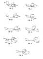
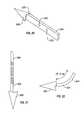
- FIGS. 2 and 3illustrate the natural curved shape and the temporary straight shape respectively, of one form of staple with attached thread in accordance with the present invention.
- FIG. 4is an enlarged sectional view of the staple guide in the bone anchor inserter device of FIG. 1 .
- FIG. 5 ais an end view illustrating the staple guide of FIG. 4;
- FIG. 5 bis similar to FIG. 5 a, illustrating a modification in the construction of the staple guide.
- FIGS. 6, 7 a, and 7 bare views similar to FIGS. 4, 5 a, and 5 b, respectively, illustrating a modification in the construction of the staple guide.
- FIG. 8illustrates various stages in applying the staple and thread of FIGS. 2 and 3 to the pubic bone when a procedure for treating urinary stress incontinence is performed (or for insertion into other bone when treating other conditions).
- FIGS. 9-11illustrate modifications in the construction of the bone anchor inserter device of FIG. 1 .
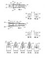
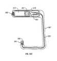
- FIG. 12 ais a left side view of a stapler or pusher/impact type bone anchor inserter, in accordance with the present invention, with a front view of a loading key shown as well.
- FIG. 12 bis a bottom, back, and left side perspective view (on a different scale) of the stapler or pusher/impact type bone anchor inserter of FIG. 12 a.
- FIG. 12 cis a right cross-sectional view of a screwdriver-type bone anchor inserter for rotational insertion of bone screws.
- FIGS. 12 d (1)- 12 d (6)are front views of bone screws for use in the screwdriver-type bone anchor inserter of FIG. 12 c. Several different bone screw embodiments are shown, in accordance with the present invention.
- FIG. 12 eis a right cross-sectional view of a spring loaded C-shaped inserter, having an alternative driving mechanism, a spring mechanism.
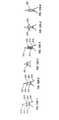
- FIGS. 13-19illustrate other forms of staple-thread units which may be used in accordance with the present invention.
- FIG. 20is a bottom, front and left side perspective view of one form of a bone anchor, a staple, used with the stapler/bone anchor inserter described herein.
- FIG. 21is a front view of the stapler type bone anchor shown in FIG. 20 which can be used with the staple inserter.
- a bone anchor with an offset tipis shown, i.e. a bone anchor in which the central, longitudinal axis of the tip is offset from the central, longitudinal axis of the bone anchor's shaft or body.
- An offset tipcan be provided to a staple type bone anchor or to a screw type bone anchor to protect the suture from accidentally becoming severed during implantation.
- FIG. 22is a front view of the curved shape that a bone anchor (e.g. that shown in FIG. 20 or 21 ) can achieve after insertion into bone, a consequence of it having been formed of shape memory alloy and the temperature of the staple having changed to its state changing temperature.
- a bone anchore.g. that shown in FIG. 20 or 21
- FIG. 23is a perspective view of a catheter inserted into the bladder of a patient in accordance with the method of the present invention, with a physician's (or health care worker's) two fingers partially inserted into a woman's vagina.
- FIG. 24is a perspective view of the hand of the physician pressing the anterior vaginal wall of a patient against the posterior of her pubic bone, according to the present method (with the catheter in place).
- FIG. 25is a perspective view of the non-linear bone anchor inserter (in this case, a C-shaped inserter) inserted into the vaginal canal, with the anchor housing pressing the anterior vaginal wall of the patient against her pubic bone. Notice that the physician's hand, which is used for triggering the mechanism of the inserter, is outside of the vagina and that the physician can pull the handle of the inserter against the resistive force of the pubic bone. An enlarged inset cross-sectional view is provided of the insertion step of the bone anchor into the pubic bone.
- FIG. 26is a perspective view of the hands of the physician tying the suture threads affixed to the bone anchors (the bone anchors having first been implanted into the patient's pubic bone).
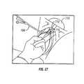
- FIG. 27is a perspective view, similar to that shown in FIG. 23, of an initial step in sling procedures of the present invention, in which a catheter is inserted into the bladder of a patient in accordance with the method of the present invention, with a physician's (or health care worker's) two fingers partially inserted into a woman's vagina.
- the balloonis inflated with water and located just above the bladder neck. This step is performed after a first initial step consisting of a perioperative antibiotic treatment, anaesthesia, and disinfection and cleansing of the surgical area (as are all known in the art).
- FIG. 28is a perspective view of a subsequent initial step in the sling procedures of the present invention, similar to that shown in FIG. 24, in which the physician presses the anterior vaginal wall against the posterior pubic bone.
- FIG. 29is a cross sectional view of a patient, including the inserter and the physician's hands, showing a subsequent initial step in the sling procedures of the present invention, in which the anchor inserter is inserted into the vagina, and the bone anchor tip is inserted through the vaginal wall into the cortex of the pubic bone (shown enlarged in the inset of the drawing).
- FIG. 30is a cross sectional view of a patient's vagina showing a first step in the submucosal tunnel technique of the sling procedures of the present invention, in which a second screw is inserted on the contralateral side of the urethral axis, which step is performed after the initial preparatory steps shown in FIGS. 27-29.
- FIG. 31is a cross sectional view of a patient's vagina showing a subsequent step in the submucosal tunnel technique of the sling procedures of the present invention, in which a midline incision is cut in the anterior vaginal mucosa, just below the bladder neck.
- FIG. 32is a cross sectional view of a patient's vagina showing a subsequent step in the submucosal tunnel technique of the sling procedures of the present invention, in which a right angle dissector is passed submucosally from each vaginal mucosal opening to the midline incision.
- FIG. 33is a cross sectional view of a patient's vagina showing a subsequent step in the submucosal tunnel technique of the sling procedures of the present invention, in which the tunnels created by the anchor's sutures are dilated using a medical dilator.
- FIG. 34is a cross sectional view of a patient showing a subsequent step in the submucosal tunnel technique of the sling procedures of the present invention, in which two sutures on one side of the midline incision are threaded through two holes in one side of the sling (one suture per hole), and in which the sling material is passed through the submucosal tunnel from one side to the other.
- FIG. 35is a cross sectional view of a patient's vagina showing a subsequent step in the submucosal tunnel technique of the sling procedures of the present invention, in which the sling is loosely tied to the pubic bone.
- FIG. 36is a cross sectional view of a patient's vagina showing a subsequent step in the submucosal tunnel technique of the sling procedures of the present invention, in which the sling's tension is tested, preferably using a right angle dissector, and adjusted, if necessary. Once the desired tension is present, sling is tightly secured.
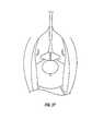
- FIG. 37is a cross sectional view of a patient's vagina showing a subsequent step in the submucosal tunnel technique of the sling procedures of the present invention, in which the vaginal mucosal incisions are closed with sutures.
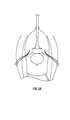
- FIG. 38is a cross sectional view of a patient's vagina showing a first step in the anterior wall dissection technique of the sling procedures of the present invention, in which a U-shaped incision is made.
- the step of FIG. 38is performed after conducting the initial steps shown in FIGS. 27-29, the insertion of a second screw as in FIG. 30, and after performing a cystoscopy to verify bladder and urethral integrity.
- a U-shaped incisionis made in the vaginal mucosa, as shown in the figure, with the flap dissected in the anterior vaginal mucosa, exposing the periurethral tissue. Any other technique of vaginal wall dissection can also be performed.
- FIG. 39is a cross sectional view of a patient's vagina showing a subsequent step in the anterior wall dissection technique of the sling procedures of the present invention, in which the tunnels created by the anchor's sutures are dilated.
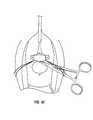
- FIG. 40is a cross sectional view of a patient's vagina showing a subsequent step in the anterior wall dissection technique of the sling procedures of the present invention, in which the sling is placed below the bladder neck, on the exposed tissue, and the sling is tied to the pubic bone surface by threading two sutures, on each side of the sling, through the two holes on that side.
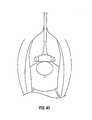
- FIG. 41is a cross sectional view of a patient's vagina showing a subsequent step in the anterior wall dissection technique of the sling procedures of the present invention, in which two sutures are tied on one side of the sling to affix the sling to the pubic bone surface, and in which, only one knot is tied on the other side, to enable fine tuning of the sling tension.
- FIG. 42is a cross sectional view of a patient's vagina showing a subsequent step in the anterior wall dissection technique of the sling procedures of the present invention, in which the sling's tension is checked, preferably using a right angle dissector. Once the desired tension is present, sling is tightly secured.
- FIG. 43is a cross sectional view of a patient's vagina showing a subsequent step in the anterior wall dissection technique of the sling procedures of the present invention, in which the vaginal muscosal flap is closed with absorbable sutures.
- FIG. 44is a cross sectional view of a patient's vagina showing the use of a non-linear anchor inserter, for insertion of a non-screw anchor into the public bone, in accordance with a sling procedure of the present invention, as disclosed herein.
- FIG. 45 ( a )is a cross sectional view showing a sling attached upward and forward to the mid-pubic bone, just below the Cooper's ligament.
- FIG. 45 ( b )is a further view of the sling of FIG. 45 ( a ) shown as a view of the posterior pubic bone.
- FIG. 46is a plan view of a preferred sling design, in accordance with the present invention.
- the stapler device illustrated in FIG. 1comprises a housing, generally designated 2 , including a handle 4 which is manually grippable by the user.
- the illustrated stapler devicemay be pneumatically powered and therefore includes a connector 6 at the bottom of the handle 4 for attaching a tube 8 connectible to a source of pressurized air.
- Housing 2further includes an elongated barrel 10 having a staple guide 12 at its end for enabling the staple 14 to be ejected. Ejection of the staple 14 is effected by an ejector pin 16 which is driven into sharp impact against the base of the staple 14 by the air pressure supplied from the pressurized air tube 8 .
- Handle 4includes a trigger 18 which, when depressed, applies an air pressure pulse to ejector pin 16 to cause it to impact against the base of staple 14 and thereby to eject the staple out through the end of guide 12 .
- trigger 18which, when depressed, applies an air pressure pulse to ejector pin 16 to cause it to impact against the base of staple 14 and thereby to eject the staple out through the end of guide 12 .
- the staple 14 ejected from the guide 12 at the end of barrel 10 in FIG. 1has a suture thread 20 secured to the staple and ejected with it.
- the stapleis driven per vaginally into the patient's pubic bone, and the thread 20 may then be used for securing the bladder neck and proximal urethra.
- the staple 14 in FIG. 1is made, in one embodiment, of elastic material.
- the stapleis preferably shaped into the curved form illustrated at 14 ′ in FIG. 2 while it is in its “normal” condition, and is deformed into the straight form shown at 14 ′′ in FIG. 3 while in a stressed condition. It is loaded into the stapler and ejected therefrom while in its straight stressed condition. After it has been so ejected, it returns to its curved form shown at 14 ′ in FIG. 2, thereby better securing the staple to the bone tissue which it penetrated when it was ejected from the staple guide 12 .
- the staple 14is formed with a pointed end 14 a to enable it to penetrate the bone, and with a hole 14 b approximately midway of its length for receiving the thread 20 , similar to the manner in which a thread is received in the eye of a needle.
- FIGS. 4 and 5more particularly illustrate the staple guide 12 from which the staple 14 , including its attached thread 20 , is ejected.
- this guideis formed with a pair of slots 22 to accommodate the thread 20 .
- the thread 20moves through slot 22 , thereby permitting the staple guide 12 to snugly fit around the ejected staple 14 .
- FIGS. 6 and 7illustrate a modification in the construction of the staple guide 12 in order to accommodate the thread 20 secured to the staple 14 .
- the inner surface of the staple guide 12is formed with a pair of recesses 22 a for receiving the two sides of the thread 20 .
- the staple 14is loaded into the staple guide 12 while the staple is in its straight condition as illustrated at 14 ′′ in FIG. 3 .
- Depressing trigger 18causes a high-pressure pulse of air to be applied to ejector pin 16 .
- This pulsecauses ejector pin 16 to impact against the end face 14 c of the staple 14 , thereby driving the staple into the bone as shown in FIGS. 8 a and 8 b.
- the stapleAs soon as the staple penetrates the bone, it starts to return to its normal, curved shape as shown in FIGS. 8 c and 8 d.
- the stapleis thus firmly anchored to the bone with its attached thread 20 extending through the opening formed by the staple through the bone, as shown in FIG. 8 e.
- the stapler barrel 10 in FIG. 1is preferably of a flexible plastic tube.
- FIG. 9illustrates a variation wherein the stapler barrel is in the form of a closed helical wire 110 enclosed within a thin flexible tube 111 , which increases the flexibility of the barrel and thereby facilitates its placement at the proper direction.
- FIG. 10illustrates a variation wherein the barrel, therein designated 210 , is a stiff or rigid tube.
- FIG. 11illustrates a further variation wherein the stapler, therein designated 302 , includes two barrels 310 a, 310 b in parallel relation to each other to enable two staples with attached threads to be ejected at the same time.
- each of the staple guides 321 a, 312 breceives a staple-thread unit 314 a, 314 b ejected by an ejector pin 316 a, 316 b received in the respective barrel, and both ejector pins are driven at the same time by high pressure pulses produced upon depression of the trigger 318 .
- the present inventionalso relates to an improved inserter device (whether a stapler or screw inserter) for inserting a bone anchor (whether staple or screw) into a patient, wherein the inserter device is non-linear.
- the inserteris shaped in a “C” shaped design which allows the physician's pulling force to press the staple or screw into the bone before and during ejection or screwing of a bone anchor.
- the physicianis able to use a pulling force against the resistive force of the pubic bone rather than a pushing force against the recoil of the inserter.
- the devicealso allows the physician to use the weight of a patient's body as counterbalancing leverage to minimize recoil of the staple during ejection of a staple into the patient's body.
- the novel geometry of the inserterallows the physician to hold the inserter and perform a per vaginal procedure with one hand out of the vagina.
- a stapler or bone anchor inserter 810having a handle 815 , trigger 820 , anchor housing 825 and an anchor shield 830 .
- Handle 815is attached to body 855 of the bone anchor inserter 810 .
- Body 855is curved such that when attached to the handle 815 the two components form a “C” shaped apparatus.
- the insertercan be formed as a V-shape or another non-linear configuration.
- a drive pinforces the anchor 835 (See FIG. 20, without suture thread shown, for ease of illustration) out of anchor housing 825 and anchor shield 830 (see FIG. 12 a ) of the stapler 810 .
- the stapler or bone anchor inserter 810may be made of any suitable material, for example, stainless steel which meets surgical instrument standards.
- An internal spring mechanism(not shown in FIG. 12 a or 12 b ) is in mechanical contact with the ejector pin (which is placed in contact with the bone anchor or staple).
- the ejector pincomes into contact with the bone anchor or staple 835 , providing the forcible ejecting, pushing and implanting of the bone anchor or staple 835 , with attached suture thread, into bone.
- the ejection mechanismis activated by the trigger 820 which can be provided with a safety release or lock-out 842 to prevent accidental, premature staple discharge.
- the tail end of the anchor 835(best seen in FIGS. 20-22) is held in a nearly straight configuration within anchor housing 825 until ejection.
- the anchor housing 825is attached to the inserter 810 prior to use, remains attached to the inserter during anchor insertion and, after insertion of the bone anchor, is disposable, with a new anchor housing with anchor being installed onto the inserter.
- a retractable anchor shield 830surrounds and protects the sharp conical front end of the anchor, to ease insertion.
- the bone anchor 835(the specific anchor 844 is shown in FIGS. 20-22) is implanted into the bone without pre-drilling of a hole in the patient's bone.
- the bone anchor inserter 810After cocking the internal spring mechanism using a loading key 840 , which is placed into and rotated within loading socket 845 , and attaching a bone anchor housing 825 (with suture attached to anchor 835 or 844 ), the bone anchor inserter 810 is ready for use.
- the spring mechanismstores the mechanical energy necessary to eject and insert the anchor into bone. In one preferred embodiment, this is approximately 2.95 Joule ⁇ 10%.
- FIG. 12 cillustrates a C-shaped bone anchor driver in a shape allowing rotational insertion of a bone screw into a bone through a body orifice such as the vagina.
- the inserterconsists of a handle 870 having an internal battery 875 , a battery-operated rotating motor 881 , with a finger switch 880 to control operation.
- the motor's rotational movementis linked to a shaft adapter 883 to allow more torque with less speed of rotation.
- the rotational poweris transferred from the gear box through the inserter device to the screw adapter 890 , via a flexible, rotatable shaft 895 , and a flexible shaft guide 897 may be provided, as well, if desired.
- the anchorin this case, a screw
- screw adapter 890which is at the second end of the inserter, the end opposite the handle.
- the anchor or screwis disconnected from the inserter once the screw is implanted into the bone surface.
- the screw protector or retractable shield 900shields the sharp tip of the screw until it is well positioned, so as not to accidentally damage the patient's tissue. Once the inserter is well positioned, pulling the handle 870 retracts the spring-biased screw protector or retractable shield 900 thereby allowing the screw's sharp tip to penetrate the soft tissue.
- the screw protector or retractable shield 900may have a rough edge surface, or small pins or sharp tips to hold the soft tissue (such as vaginal mucosa) and to prevent surrounding tissue rotation as the screw rotates and penetrates the soft tissue and into the bone.
- depressing switch 880activates the motor 881 which drives the flexible shaft 895 connected to the screw adaptor 890 . This causes a screw (see FIGS. 12 d (1)-(6)) to become embedded into the bone.
- FIG. 12 eshows an alternative, spring-loaded C-shaped inserter, having a different spring mechanism to that shown in FIGS. 12 a & 12 c.
- the inserterhas a dual spring mechanism which allows the user to impart more energy and impact to the anchor during implantation into the bone.
- this inserterhas the significant advantage that the two spring design results in cancellation of the rotational movement that the inserter may have during release. This results in a more stable anchor insertion.
- This alternative inserter embodimentutilizes a hammer 1000 which impacts and ejects an anchor into a bone.
- second spring 1015can expand outward from its compressed state against second weight 1020 to force second rod 1025 to the right to allow rotation of connecting cam 1010 .
- Connecting cam 1010is connected to both second rod 1025 and to main rod 1030 . Rotation of the connecting cam 1010 in the counterclockwise direction by second rod 1025 moving to the right, as shown in FIG. 12 e, moves main rod 1030 away from its locking or “up” position against main weight 1035 which allows the spring 1040 to expand to cause hammer 1000 to impact a bone anchor.
- main spring 1040is connected to main weight 1035 , with main weight 1035 slidably connected to hammer 1000 .
- a friction disk 1045is provided above main spring 1040 .
- a hammer guide 1041is provided around a portion of the hammer 1000 , as shown in FIG. 12 e. Before activation of the inserter, main spring 1040 is maintained in a compressed position.
- main spring 1040moves downwardly, with main weight 1035 , allows main spring 1040 to expand outward, forcing main weight 1035 to be slammed against ring 1043 , secured to the end of the hammer. This causes hammer 1000 to rapidly move downward. The release of the energy stored in main spring 1040 thus forces hammer 1000 downward to impact and eject a bone anchor out of recess 1060 and into a bone.
- FIGS. 13-19illustrate other constructions of staple-thread units which may be used.
- the unit illustrated in FIG. 13includes a staple 114 and a thread 120 similar to the construction illustrated in FIGS. 2 and 3, except that the hole 114 b through which the thread 120 is passed is at the rear end of the staple, rather than at the middle.
- FIG. 14illustrates a construction wherein the staple 214 is provided with a bore 214 b extending at an angle to the longitudinal axis of the staple 214 with the end of the thread 220 received and fixed therein by crimping the staple.
- FIG. 15illustrates a construction wherein the bore 314 b is in the base 314 c of staple 314 and extends along or parallel to the longitudinal axis of the staple 314 , the thread 320 being received within the bore 314 b and fixed therein by crimping the staple.
- FIG. 16illustrates a construction similar to that of FIG.
- FIG. 17illustrates a further variation wherein the staple 514 is formed with a plurality of barbs 515 projecting from its outer surface, to fix the staple to the bone into which it has penetrated.
- the thread 520is passed through a hole 514 b in the staple.
- FIG. 18illustrates a staple made of bent wire.
- FIG. 19illustrates a staple with a split tail 714 c, which is straightened under stress when first inserted into the staple guide 12 and splits after ejection, a consequence of its shape memory.
- the bone anchorcan be made of a single piece of a shape memory alloy, such as the nickel-titanium alloy called Nitinol.
- a shape memory alloysuch as the nickel-titanium alloy called Nitinol.
- One form of bone anchorfor example, which can be used with the present invention, has a conical front end 846 (See FIGS. 20-22) with diameters ranging from 1.9-2.4 mm, and a tail end with a nearly rectangular cross-section.
- the tail portionis preferably 6.0 mm long with a width that ranges from 1.9-2.4 mm and a thickness of about 0.6 mm.
- the anchor tail 844contains two holes 848 and 850 which are used for threading the suture.
- An example of a suture thread which can be used in the bone anchoris sterile polypropelene monofilament No. 1.
- the bone anchoris depicted in FIGS. 20 through 22.
- the longitudinal axis of the tail endis offset from the center axis of the conical tip 846 . This is best seen in FIGS. 21 and 22.
- the bone anchor 835soon heats to body temperature, changing by the characteristics of shape memory alloy, for example, from a straight to a curved shape, i.e., the longitudinal axis of the anchor changes, after insertion. This is shown in FIG. 22 .
- the end of the tail and the rear end of the conical tipafter heating of the bone anchor sufficient to change its shape, will subtend an angle of about 75° ⁇ 16° (as seen in FIG. 22 ).
- This change of shapeis because of the fabrication of the anchor from shape memory alloy.
- This curved shapefacilitates fixation of the anchor within the bone and inhibits the inadvertent removal of the anchor.
- the present inventionprovides an apparatus and method which (in the anchor ejection or screwing mode) does not require pre-drilling of the bone or soft tissue dissection to insert the bone anchor into the bone. Similarly, the bone anchor does not require cement or other fixative to remain in place.
- the bone anchor and bone anchor inserterare supplied sterile.
- the inserter (and its loading key)should, of course, be cleaned and sterilized before each new patient procedure. Cleaning is accomplished by washing and rinsing the inserter and loading key with water and a liquid detergent, while scrubbing with a flexible brush to completely remove all traces of blood.
- the inserter and loading keyshould be rinsed thoroughly with water to remove detergent residues. Panels in the inserter body allow access for cleaning. Once cleaned, the inserter and loading key may be cloth or air dried.
- the inserter and loading keymay be sterilized by heat or steam autoclave, or gas (EtO), in accordance with hospital procedures for sterilization of stainless steel surgical instruments.
- a bone screwAs shown in FIG. 12 d (1), a bone screw is disclosed having a conical tip 910 and a screw body 915 .
- the diameter of each of the screw threads 928(the grooves, recesses or indentations in the material of the screw) is constant along the screw body.
- the suture 925is attached at a hole in the end 927 of the bone screw.
- FIG. 12 d (2)shows a bone screw 920 with a more tapered conical tip 930 and a screw body 935 .
- the diameter of the screw threads 940vary. The diameters of the screw threads 940 increase from small diameters near the apex of the conical tip to greater diameters near the screw body 935 .
- the screw threads 940can be located on all or a portion of the screw body as well, if desired.
- the suture 950is attached through a hole in the end 947 of the screw.
- FIG. 12 d (3)is similar to FIG. 12 d (1). In this figure, however, the suture is shown attached through a hole in the middle 952 of the bone screw.
- FIG. 12 dshows a bone screw 920 in which the screw threads or grooves are formed by wrapping spring wire 956 around a solid body.
- the bodyhas a leading tip 970 and a shaft 972 , of smaller relative cross section.
- a trailing end 974 with a holeis provided for attaching the suture thread 976 .
- the spring wireis wrapped on the shaft 972 and maintained between leading tip 970 and the trailing end 974 .
- FIG. 12 d (5)shows a bone screw similar to that in FIG. 1 d (4).
- leaf springs 958are provided.
- Leaf springs 958are initially flattened against the side surface of the bone screw, i.e., when the screw is inserted into the bone. Upon insertion, however, the leaf springs 958 expand outward from a compressed to a non-compressed state (due to the elasticity which is characteristic of a spring) to provide greater anchoring of the bone screw within the bone.
- FIG. 12 d (6)discloses a bone screw in which the screw threads or grooves are formed by wrapping a spring plate 963 around the screw body or shaft of the screw. Here, too, the spring plate is held between the leading tip and the trailing end.
- the bone screwis typically made of a medical grade alloy such as Stainless Steel 316. Its sharp tip and small diameter allows for its penetration through the vaginal wall and the periosteum, without pre-drilling a hole. As the screw is rotated by the inserter, which may be linear, C- or V-shaped, it further enters the bone until it reaches a prescribed depth within the bone. The screw then automatically disconnects from the rotating inserter shaft.
- the medical technique of inserting a bone screw into the pubic bone through the vagina for the purposes of bladder neck suspensionis also within the scope of the present invention, as is the bone screw inserter.
- anchor device and anchor-thread unitsmay be used for other applications, e.g., for shoulder dislocations, endoscopic operations, or the like.
- the anchor insertermay also be electrically operated and may use other mechanical impact or screw-type devices for driving the anchor.
- the anchorsthemselves may be of known bio-absorbable materials.
- a 20 F urethral catheteris inserted into the bladder, and a balloon is inflated to 20 cc and retracted gently downwardly against the bladder neck.
- the surgeoninserts two fingers into the vagina, pressing the anterior vaginal wall with one finger on each side of the urethra, which is felt because of the inserted catheter.
- the bladder neck and proximal urethraare pressed against the posterior wall of the pubic bone.
- two staplesare ejected longitudinally on each side of the urethra, about 1-2 cm apart.
- the two threads on each side of the urethraare tied one to the other.
- the threadsmay be tied on the vaginal mucosa, in which case the tension will embed the threads to the sub-mucosa after some time.
- the threadsmay be tied under the vaginal mucosa by passing one of the threads on the same side.
- the threadsmay be made of a monofilament non-absorbent material, as well as of an absorbent material, dependent on the preference of the physician.
- FIGS. 23-26Further methods of the present invention is shown in FIGS. 23-26. With the patient in lithotomy position, the surgical area and the vagina are cleaned and disinfected. A Foley catheter is inserted inside the bladder, and the balloon is inflated with approximately 10-20 cc of water. The catheter is then pulled backwardly to locate the balloon just above the bladder neck as shown in FIG. 23 .
- the catheter (within the urethra) and the balloon at the bladder neckare palpated by the physician's finger tips. Pressing the fingers upward and forward, the anterior vaginal wall is pressed against the posterior pubic bone surface, as shown in FIG. 24 .
- the bone anchor inserter(whether a stapler/impact or a screwdriver-type inserter) is then inserted into the vagina (see FIG. 25) near the bladder neck and approximately 2 cm. to the side of the urethra.
- the inserteris pulled against the pubic bone. Notice that the triggering hand of the physician is external to the vagina and that the force applied by the physician is one of pulling against the resistive force of the pubic bone.
- the tip of the bone anchor 835touches and penetrates the vaginal wall and enters the cortex of the pubic bone.
- the trigger 820(or switch 880 , for the screw inserter) is pulled and the bone anchor 835 penetrates and fixates within the bone.
- the physicianpulls up on the handle 815 of the stapler or bone anchor inserter 810 .
- the physicianlifts the anchor 835 or screw 920 and anchor housing 825 or screw adaptor 890 against the pubic bone. A portion of the weight of the patient resists the lifting of the inserter, pressing against it firmly.
- the lifting of the stapler or bone anchor inserter 810is performed against some of the weight of the patient, ensuring a firm and effective contact of the anchor tip with the pubic bone.
- the penetration of the tip of the bone anchor into the bone cortex before ejection or screwingfurther increases the stability of the ejection into the pubic bone.
- the use of the non-linear or C-shaped inserterallows at least part of the patient's weight to counterbalance the recoil of the spring mechanism.
- the patient's body weight, along with the inserter's shape,provides the physician with suitable leverage for ensuring penetration of the anchor 835 or screw 920 into the pubic bone. This is especially important in the use of the present bone anchor device which, in the case of the ejected anchor, seeks to avoid pre-drilling of a hole, followed by anchor insertion.
- Releasing the safety 842 first and then pressing the trigger 820 of the deviceactivates the inserter spring mechanism (not shown) which ejects the anchor 835 to a prescribed depth within the bone (e.g. 2.5 mm) so that no portion of the anchor protrudes from the bone surface.
- the end of the inserterwill experience a reaction force when the staple is ejected, the weight of the patient, pressing downward against the inserter end (anchor housing 825 and anchor shield 830 ) combined with the force exerted by the physician by pulling the handle 815 of the bone anchor inserter 810 upward (so that the end of the inserter is forced against the weight of the patient and the penetration of the tip of the anchor into the pubic bone before ejection) result in a firm and solid contact between the inserter and the pubic bone during and through the insertion process, minimizing any problems of insertion associated with stapler recoil.
- Bone anchorsare inserted on each side of the urethral axis or parallel along each side of the posterior aspect of the superior pubic bone ramus, lateral to the symphysis pubis.
- two bone anchorsare inserted on each side of the urethral axis or parallel along each side of the posterior aspect of the superior pubic ramus, about 2 cm. lateral to the symphysis pubis.
- Each pair of two bone anchorsis inserted with the two bone anchors in a pair approximately 2 cm. apart. Cystoscopy is then performed to verify that there are no bladder or urethral perforations.
- the suture threads extending from the anchorsare then tied.
- the suture threadsare tied from one bone anchor to the other, ipsilaterally on each side of the urethra, as shown in FIG. 26 . They may be tied either above the vaginal mucosa or below the vaginal mucosa (using a deshamp) with or without vaginal dissection. The tie may be left as is or pushed beneath the mucosa.
- Suprapubic or Foley urethral catheterizationis then performed.
- the suprapubic catheteris to remain until complete bladder emptying is achieved by normal urination.
- Prophylactic antibioticis administered perioperatively. Physical strain and lifting by the patient is to be avoided for approximately 2-3 months.
- the threadsmay be used for engaging and elevating the urethra to the posterior pubic bone as in a “sling operation”.
- sling procedurescan be provided, in accordance with the invention. These sling procedures are preferably provided for the treatment of urinary stress incontinence as disclosed above and herein. Alternatively, it is contemplated that they may be also useful in other medical procedures to correct other anatomic pathologies and/or relieve discomforts of a patient.
- the sling procedureis a pervaginal procedure in which one or more bone anchors are inserted through the vaginal wall of the patient to enter the pubic bone, and in which suture thread and a sling are utilized to adjust the anatomic position of the bladder neck and the urethra of the patient, or more specifically, to suspend the bladder neck.
- the bone anchorsmay be bone screws and/or bone staples, and preferably have the suture suture thread already attached thereto before they are inserted into the vagina of the patient.
- insertion of the anchorsis conducted using a nonlinear inserter, preferably one of the inserters disclosed herein.
- the In-FastTM Bone Screw System and/or the In-TacTM Bone Anchor Systemis used, both of which are available from Influence, Inc. of San Francisco, Calif.
- the procedureis initiated by a pervaginal insertion of an anchor into the patient.
- a pervaginal insertion of an anchorinto the patient.
- the patientis placed under spinal, general or local anesthesia and in the lithotomy position, and the surgical area and the vagina are cleaned and disinfected.
- a Foley catheter 706is then inserted inside the bladder 710 , and the balloon 712 is inflated with approximately 10-20 cc of water. The catheter 706 is then gently pulled to locate the balloon 712 just above the bladder neck 716 as shown in FIG. 27 .
- the catheter 706is then located, within the urethra, between the physician's index and second fingers so that the finger tips are touching the balloon at the bladder neck.
- the physicianthen, by pushing his or her fingers upward and forward, presses the anterior vaginal wall against the posterior of the pubic bone 718 , as shown in FIG. 28 .
- the physicianthen inserts the bone anchor insertion device 722 (preferably a nonlinear bone screw inserter) into the vagina, below the bladder neck and lateral to the symphysis pubis, about 2 cm. to the side of the urethra.
- the inserter device 722is then pulled upward until the screw 726 presses the anterior vaginal wall 724 against the pubic bone 718 .
- an inserter 722is used having a retractable shield 730 .
- Retractable shield 730is a protective cover for the screw 726 which is designed such that the application of pressure to the shield 730 causes the shield to retract and reveal the screw.
- the shield 730can be flexible, such that it bends, contracts, or compresses when force is provided to it.
- the shield 730can rest on springs while the screw does not, so that application of pressure to the shield retracts it, while the screw remains in place.
- the screw shield 730will collapse and the tip of the bone screw 726 will become exposed so as to allow it to penetrate the vaginal wall 724 and enter the cortex of the pubic bone 718 , as shown in FIG. 29 .
- the safety lock of the inserter 722can then be released to allow deeper insertion of the screw 726 into the bone, by continuously pressing the inserter's operate button to insert the screw.
- the operate buttonis released and the inserter can be removed from the vagina for reloading.
- a submucosal tunnel technique or an anterior wall dissection techniquecan preferably be performed, as disclosed below.
- a second screw 736is inserted in the same elevation as in the first, on the contralateral side of the urethral axis, as shown in FIG. 30 .
- a cystoscopyis performed to verify bladder and urethral integrity.
- a midline incision 740(see FIG. 31) about 1.5-2 cm long is then cut in the anterior vaginal mucosa, just below the bladder neck 716 as shown in FIG. 31 .
- a right angle dissector 744is then passed submucosally from each vaginal mucosal opening to the midline incision 740 to create a submucosal tunnel 748 just below the bladder neck 716 , as shown in FIG. 32 .
- the tunnels created by the anchor's suturesare then dilated. Dilation is performed by threading one pair of sutures through the tip of a dilator 750 .
- the dilator 750is inserted into the vagina and, while pulling on the sutures, it is advanced and pushed up along the sutures, perpendicular to the pubic bone surface, as shown in FIG. 33 .
- the dilator 750touches the bone cortex, the dilator is then opened approximately 5 mm and pulled back, and out of the patient, in the open position. This procedure is then repeated for the contralateral pair of sutures.
- the slingis introduced into the vagina. As shown in FIG. 34, the two sutures 728 on one side are threaded through the two holes in one side of the sling 752 . The sling material 752 is then passed through the submucosal tunnel from one side to the other.
- a right angle clamp 758is inserted through the midline incision 740 above the sling material 752 and used to pull the sling material downwards gently, as shown in FIG. 36 .
- the sling 752should be loose enough to permit approximately 0.5 cm of sling movement. If the sling is too tight or too loose, the sling tension is adjusted (by adjusting the tension on the side with the single knot), and then, once sufficient tension has been achieved, that side of the sling is secured.
- the vaginal mucosal incisionsare then closed with absorbable sutures as shown in FIG. 37 .
- a suprapubic or urethral catheterizationis then performed.
- the draining cathetershould remain until complete bladder emptying is achieved by normal urination, normally between 1 to 2 days.
- Prophylactic antibioticsshould be administered perioperatively for approximately 5 days after the procedure, and physical strain and lifting by the patient should be avoided for 2-3 months.
- it is recommended that the lot numbers of the screws used in the procedureshould be recorded on the patient's chart.
- an anterior wall dissection techniqueis provided.
- the initial steps described above with respect to the submucosal tunnel techniqueare performed, from the antibiotic treatment through the insertion of the second screw on the contralateral side and the performance of a cystoscopy to verify bladder and urethral integrity, as disclosed above, and shown in FIGS. 27-30.
- a U or other incisionis made in the vaginal mucosa.
- the flapis dissected in the anterior vaginal mucosa, exposing the periurethral tissue as shown in FIG. 38 .
- the tunnels created by the anchor's suturesare then dilated, as shown in FIG. 39 .
- Thisis performed by threading one pair of sutures through the tip of a dilator.
- the sutureis then held, under tension, and the dilator is pushed up along the sutures, perpendicular to the pubic bone surface.
- the dilatortouches the bone cortex, the dilator is opened approximately 5 mm and pulled back, and out of the patient, in the open position. This procedure is then repeated for the contralateral pair of sutures.
- the slingis then placed below the bladder neck, on the exposed tissue.
- two suturesare threaded through the two holes in the sling on that side, a suture through each hole, as shown in FIG. 40 .
- two suturesare tied toward the pubic bone to affix the sling to the pubic bone surface.
- only one knotis tied so as to enable fine tuning of the sling tension if required, as with the submucosal tunnel technique, and as shown in FIG. 41 .
- a right angle clampis placed above the sling material and pulled downwards gently, as shown in FIG. 42 .
- the slingshould be loose enough to permit up to 0.5 cm of sling movement.
- the vaginal mucosal flapis then closed with absorbable sutures, as shown in FIG. 43 .
- a suprapubic or urethral catheterizationis then performed.
- the draining cathetershould remain until complete bladder emptying is achieved by normal urination, normally between 1 to 2 days.
- Prophylactic antibioticsshould be administered perioperatively for approximately 5 days after the procedure, and physical strain and lifting by the patient should be avoided for 2-3 months.
- it is recommended that the lot numbers of the screws used in the procedureshould be recorded on the patient's chart.
- the insertercan be discarded.
- the Submucosal Tunnel Technique and the Anterior Wall Dissectioncan be performed with a non-screw bone anchor.
- such insertionsare performed using the In-TacTM Bone Anchor System, available from Influence, Inc. of San Francisco, Calif.
- the procedureis also conducted using a pervaginal insertion of an anchor into the patient.
- a pervaginal insertion of an anchor into the patientAfter a perioperative antibiotic treatment, the patient is placed under spinal, general or local anesthesia and in the lithotomy position, and the surgical area and the vagina are cleaned and disinfected.
- the anchor inserteris then loaded with an anchor. Initially, the loading key is placed into its key hole on the inserter and the key is turned clockwise approximately one half turn until the loading key will not turn further. The first anchor is then placed within the anchor inserter.
- a Foley catheteris then inserted inside the bladder, and the balloon is inflated with approximately 10-20 cc of water, as previously described. The catheter is then gently pulled to locate the balloon just above the bladder neck, as shown in FIG. 27 .
- the catheter 706is then located, within the urethra, between the physician's index and second fingers so that the finger tips are touching the balloon at the bladder neck.
- the physicianthen, by pushing his or her fingers upward and forward, presses the anterior vaginal wall against the posterior of the pubic bone 718 , as shown in FIG. 28 .
- the bone anchor inserteris inserted into the vagina, below the bladder neck, lateral to the symphysis pubis, about 2 cm. to the side of the urethra, and pulled upward until the anchor housing is pressing the anterior vaginal wall against the pubic bone.
- the anchor shieldwill then retract or collapse and the tip of the bone anchor should be exposed to enable it to penetrate the vaginal wall and enter the cortex of the pubic bone, as also shown in FIG. 44 .
- the safety lock of the inserteris then released, and the physician pulls upwards on the handle of the inserter until an anchor is deployed.
- the safety lockwill not allow anchor deployment unless sufficient pressure is applied to the inserter handle.
- the physiciancan then continue with either the Submucosal Tunnel Technique or the Anterior Wall Dissection technique, as described above.
- FIGS. 45 ( a ) and ( b )A further embodiment of the invention in which the sling material is pervaginally suspended from the pubic bone is shown in FIGS. 45 ( a ) and ( b ).
- FIG. 45 ( a )shows a sling material wherein the sling is attached upward and forward to the mid-pubic bone, just below the Cooper's ligament. A triangle is formed by the sling material and the natural “V” of the pubic bone, providing a “free space” for the urethra which may reduce the tendency for overcorrection.
- FIG. 45 ( b )illustrates the sling of FIG. 45 ( a ), taken as a view of the posterior pubic bone.
- the sling materialis positioned as a hammock below a portion of the female anatomy (i.e. the bladder neck and/or the urethra), the sling being suspended to the posterior surface of the pubic bone by a pervaginal technique, and with the bone anchors likewise being inserted pervaginally.
- the slingis directly attached to the pubic bone without the use of intervening sutures, preferably by inserting a bone anchor through the sling material to directly attach the sling to the pubic bone.
- FIG. 46one preferred sling design is shown in FIG. 46 .
- This slingis preferably a biocompatible texturized fabric impregnated with an absorbable gelatin. It is preferred that a soft pliable material with a matrix that facilitates tissue ingrowth be used. The material can be formed with a warp knitting process. Gelatin impregnation is preferably crosslinked to a set level to control the resorption rate and reduce the potential for inflammation.
- the slingis also preferably prepunctured to facilitate the threading of suture or insertion of a bone anchor therethrough. In one preferred embodiment, the sling is approximately 5.5 cm in length and approximately 2 cm in width at its widest portion.
Landscapes
- Health & Medical Sciences (AREA)
- Life Sciences & Earth Sciences (AREA)
- Surgery (AREA)
- Animal Behavior & Ethology (AREA)
- Engineering & Computer Science (AREA)
- Biomedical Technology (AREA)
- Heart & Thoracic Surgery (AREA)
- Orthopedic Medicine & Surgery (AREA)
- General Health & Medical Sciences (AREA)
- Public Health (AREA)
- Veterinary Medicine (AREA)
- Nuclear Medicine, Radiotherapy & Molecular Imaging (AREA)
- Molecular Biology (AREA)
- Medical Informatics (AREA)
- Urology & Nephrology (AREA)
- Rheumatology (AREA)
- Transplantation (AREA)
- Cardiology (AREA)
- Oral & Maxillofacial Surgery (AREA)
- Neurology (AREA)
- Vascular Medicine (AREA)
- Prostheses (AREA)
- Surgical Instruments (AREA)
Abstract
Description
Claims (20)
Priority Applications (1)
| Application Number | Priority Date | Filing Date | Title |
|---|---|---|---|
| US10/034,958US6575984B2 (en) | 1992-11-13 | 2001-12-27 | Medical sling procedures and anchor insertion methods and devices |
Applications Claiming Priority (12)
| Application Number | Priority Date | Filing Date | Title |
|---|---|---|---|
| IL10373792AIL103737A (en) | 1992-11-13 | 1992-11-13 | Stapler device particularly useful in medical suturing |
| IL103737 | 1992-11-13 | ||
| US08/150,517US5520700A (en) | 1992-11-13 | 1993-11-10 | Stapler device particularly useful in medical suturing |
| US534895P | 1995-10-18 | 1995-10-18 | |
| US1220596P | 1996-02-23 | 1996-02-23 | |
| US08/622,598US5807403A (en) | 1992-11-13 | 1996-03-26 | Medical anchor device with suture thread and method for implantation into bone |
| US08/733,798US5972000A (en) | 1992-11-13 | 1996-10-18 | Non-linear anchor inserter device and bone anchors |
| IL127978 | 1999-01-08 | ||
| IL12797899AIL127978A0 (en) | 1999-01-08 | 1999-01-08 | Incontinence device |
| US09/287,867US6334446B1 (en) | 1992-11-13 | 1999-04-07 | Medical sling procedures and anchor insertion methods and devices |
| US09/994,276US6592610B2 (en) | 1992-11-13 | 2001-11-26 | Medical sling procedures and anchor insertion methods and devices |
| US10/034,958US6575984B2 (en) | 1992-11-13 | 2001-12-27 | Medical sling procedures and anchor insertion methods and devices |
Related Parent Applications (1)
| Application Number | Title | Priority Date | Filing Date |
|---|---|---|---|
| US09/994,276ContinuationUS6592610B2 (en) | 1992-11-13 | 2001-11-26 | Medical sling procedures and anchor insertion methods and devices |
Publications (2)
| Publication Number | Publication Date |
|---|---|
| US20020095163A1 US20020095163A1 (en) | 2002-07-18 |
| US6575984B2true US6575984B2 (en) | 2003-06-10 |
Family
ID=26683282
Family Applications (6)
| Application Number | Title | Priority Date | Filing Date |
|---|---|---|---|
| US08/733,798Expired - Fee RelatedUS5972000A (en) | 1992-11-13 | 1996-10-18 | Non-linear anchor inserter device and bone anchors |
| US09/287,867Expired - Fee RelatedUS6334446B1 (en) | 1992-11-13 | 1999-04-07 | Medical sling procedures and anchor insertion methods and devices |
| US09/994,276Expired - LifetimeUS6592610B2 (en) | 1992-11-13 | 2001-11-26 | Medical sling procedures and anchor insertion methods and devices |
| US10/034,958Expired - LifetimeUS6575984B2 (en) | 1992-11-13 | 2001-12-27 | Medical sling procedures and anchor insertion methods and devices |
| US10/034,960Expired - LifetimeUS6575998B2 (en) | 1992-11-13 | 2001-12-27 | Medical sling procedures and anchor insertion methods and devices |
| US10/034,959AbandonedUS20020095181A1 (en) | 1992-11-13 | 2001-12-27 | Medical sling procedures and anchor insertion methods and devices |
Family Applications Before (3)
| Application Number | Title | Priority Date | Filing Date |
|---|---|---|---|
| US08/733,798Expired - Fee RelatedUS5972000A (en) | 1992-11-13 | 1996-10-18 | Non-linear anchor inserter device and bone anchors |
| US09/287,867Expired - Fee RelatedUS6334446B1 (en) | 1992-11-13 | 1999-04-07 | Medical sling procedures and anchor insertion methods and devices |
| US09/994,276Expired - LifetimeUS6592610B2 (en) | 1992-11-13 | 2001-11-26 | Medical sling procedures and anchor insertion methods and devices |
Family Applications After (2)
| Application Number | Title | Priority Date | Filing Date |
|---|---|---|---|
| US10/034,960Expired - LifetimeUS6575998B2 (en) | 1992-11-13 | 2001-12-27 | Medical sling procedures and anchor insertion methods and devices |
| US10/034,959AbandonedUS20020095181A1 (en) | 1992-11-13 | 2001-12-27 | Medical sling procedures and anchor insertion methods and devices |
Country Status (6)
| Country | Link |
|---|---|
| US (6) | US5972000A (en) |
| EP (1) | EP0904015A4 (en) |
| JP (1) | JP2000505336A (en) |
| AU (1) | AU730285B2 (en) |
| CA (1) | CA2247464A1 (en) |
| WO (1) | WO1997030638A1 (en) |
Cited By (36)
| Publication number | Priority date | Publication date | Assignee | Title |
|---|---|---|---|---|
| US20020183762A1 (en)* | 2001-06-01 | 2002-12-05 | Ams Research Corporation | Bone anchor inserters and methods |
| US20030220538A1 (en)* | 2002-03-01 | 2003-11-27 | Bernard Jacquetin | Method and apparatus for treating pelvic organ prolapses in female patients |
| US20030225424A1 (en)* | 1998-11-23 | 2003-12-04 | Benderev Theodore V. | System for securing sutures, grafts and soft tissue to bone and periosteum |
| US20040006353A1 (en)* | 2002-04-30 | 2004-01-08 | Bosley Rodney W. | Sling for supporting tissue |
| US6730110B1 (en) | 1999-01-08 | 2004-05-04 | Ams Research Corporation | Tack device |
| US20050004424A1 (en)* | 1998-04-24 | 2005-01-06 | Shlomo Raz | Methods and apparatus for correction of urinary and gynecological pathologies, including treatment of male incontinence, and female cystocele |
| US6843796B2 (en) | 1999-06-04 | 2005-01-18 | Ams Research Corporation | Bone suturing device |
| US20050288708A1 (en)* | 2004-06-25 | 2005-12-29 | Kammerer Gene W | Soft tissue fastener having integral biasing section |
| US20060196788A1 (en)* | 2005-02-02 | 2006-09-07 | Peter Komarnycky | Packaging assembly for surgical mesh implants |
| US20070005076A1 (en)* | 2005-06-20 | 2007-01-04 | Ams Research Corporation | Medical screwdrivers and methods |
| US20070067034A1 (en)* | 2005-08-31 | 2007-03-22 | Chirico Paul E | Implantable devices and methods for treating micro-architecture deterioration of bone tissue |
| US20070112384A1 (en)* | 2005-11-15 | 2007-05-17 | Conlon Sean P | Suture anchor applicator |
| US20080300607A1 (en)* | 2005-12-28 | 2008-12-04 | C.R. Bard, Inc. | Apparatus and Method for Introducing Implants |
| US20090005782A1 (en)* | 2007-03-02 | 2009-01-01 | Chirico Paul E | Fracture Fixation System and Method |
| US7527588B2 (en) | 2004-09-15 | 2009-05-05 | Ethicon, Inc. | System and method for surgical implant placement |
| US20090216260A1 (en)* | 2008-02-20 | 2009-08-27 | Souza Alison M | Interlocking handle |
| US20090276048A1 (en)* | 2007-05-08 | 2009-11-05 | Chirico Paul E | Devices and method for bilateral support of a compression-fractured vertebral body |
| US20100069913A1 (en)* | 2005-08-31 | 2010-03-18 | Chirico Paul E | Threaded bone filling material plunger |
| US20100168748A1 (en)* | 2008-07-16 | 2010-07-01 | Knopp Peter G | Morselizer |
| US20100217335A1 (en)* | 2008-12-31 | 2010-08-26 | Chirico Paul E | Self-expanding bone stabilization devices |
| US20100292732A1 (en)* | 2009-05-12 | 2010-11-18 | Foundry Newco Xi, Inc. | Suture anchors with one-way cinching mechanisms |
| US8206280B2 (en) | 2007-11-13 | 2012-06-26 | C. R. Bard, Inc. | Adjustable tissue support member |
| US8480559B2 (en) | 2006-09-13 | 2013-07-09 | C. R. Bard, Inc. | Urethral support system |
| US8845512B2 (en) | 2005-11-14 | 2014-09-30 | C. R. Bard, Inc. | Sling anchor system |
| US9463010B2 (en) | 2009-05-12 | 2016-10-11 | The Foundry, Llc | Methods and devices to treat diseased or injured musculoskeletal tissue |
| US20170303912A1 (en)* | 2000-06-22 | 2017-10-26 | Arthrex, Inc. | Knotless tissue fixation assembly |
| US10299842B2 (en) | 2013-12-20 | 2019-05-28 | Crossroads Extremity Systems, Llc | Bone plates with dynamic elements |
| US10383624B2 (en) | 2008-10-24 | 2019-08-20 | The Foundry, Llc | Methods and devices for suture anchor delivery |
| US10492841B2 (en) | 2014-07-10 | 2019-12-03 | Crossroads Extremity Systems, Llc | Bone implant and means of insertion |
| US10945725B2 (en) | 2017-02-06 | 2021-03-16 | Crossroads Extremity Systems, Llc | Implant inserter |
| US11179149B2 (en) | 2017-02-07 | 2021-11-23 | Crossroads Extremity Systems, Llc | Counter-torque implant |
| US11202626B2 (en) | 2014-07-10 | 2021-12-21 | Crossroads Extremity Systems, Llc | Bone implant with means for multi directional force and means of insertion |
| US11317951B2 (en) | 2013-12-20 | 2022-05-03 | Crossroads Extremity Systems, Llc | Bone plates with dynamic elements |
| USD961081S1 (en) | 2020-11-18 | 2022-08-16 | Crossroads Extremity Systems, Llc | Orthopedic implant |
| US11744726B2 (en) | 2013-08-01 | 2023-09-05 | Cook Medical Technologies Llc | Tissue adjustment implant |
| US12059183B2 (en) | 2020-07-31 | 2024-08-13 | Crossroads Extremity Systems, Llc | Bone plates with dynamic elements and screws |
Families Citing this family (448)
| Publication number | Priority date | Publication date | Assignee | Title |
|---|---|---|---|---|
| IL127978A0 (en) | 1999-01-08 | 1999-11-30 | Influence Med Tech Ltd | Incontinence device |
| US6406480B1 (en)* | 1992-11-13 | 2002-06-18 | American Med Syst | Bone anchor inserter with retractable shield |
| US6635058B2 (en) | 1992-11-13 | 2003-10-21 | Ams Research Corporation | Bone anchor |
| US5972000A (en) | 1992-11-13 | 1999-10-26 | Influence Medical Technologies, Ltd. | Non-linear anchor inserter device and bone anchors |
| SE506164C2 (en)* | 1995-10-09 | 1997-11-17 | Medscand Medical Ab | Instruments for the treatment of urinary incontinence in women |
| US6053935A (en) | 1996-11-08 | 2000-04-25 | Boston Scientific Corporation | Transvaginal anchor implantation device |
| AU6329598A (en)* | 1997-02-13 | 1998-09-08 | Boston Scientific Ireland Limited, Barbados Head Office | Stabilization sling for use in minimally invasive pelvic surgery |
| AU6329498A (en)* | 1997-02-13 | 1998-09-08 | Boston Scientific Ireland Limited, Barbados Head Office | Percutaneous and hiatal devices and methods for use in minimally invasive pelvicsurgery |
| US6599235B2 (en)* | 1997-03-18 | 2003-07-29 | American Medical Systems Inc. | Transvaginal bone anchor implantation device |
| US6039686A (en)* | 1997-03-18 | 2000-03-21 | Kovac; S. Robert | System and a method for the long term cure of recurrent urinary female incontinence |
| JP2001517999A (en)* | 1998-01-27 | 2001-10-09 | サイメド ライフ システムズ,インコーポレイテッド | Protective sheath for transvaginal anchor implantation device |
| US6096041A (en)* | 1998-01-27 | 2000-08-01 | Scimed Life Systems, Inc. | Bone anchors for bone anchor implantation device |
| WO1999047050A2 (en) | 1998-03-20 | 1999-09-23 | Scimed Life Systems, Inc. | Endoscopic suture systems |
| WO1999058074A2 (en)* | 1998-05-12 | 1999-11-18 | Scimed Life Systems, Inc. | Manual bone anchor placement devices |
| ATE371409T1 (en)* | 1998-05-21 | 2007-09-15 | Christopher J Walshe | SYSTEM FOR FIXING TISSUE |
| US20010004704A1 (en) | 1998-11-02 | 2001-06-21 | Barry N. Gellman | Transvaginal suture spacer devices and methods of use |
| US20050004576A1 (en)* | 1998-11-23 | 2005-01-06 | Benderev Theodore V. | System for securing sutures, grafts and soft tissue to bone and periosteum |
| US6200330B1 (en)* | 1998-11-23 | 2001-03-13 | Theodore V. Benderev | Systems for securing sutures, grafts and soft tissue to bone and periosteum |
| US7410460B2 (en)* | 1998-11-23 | 2008-08-12 | Benderev Theodore V | System for securing sutures, grafts and soft tissue to bone and periosteum |
| DE69931018T2 (en) | 1998-12-30 | 2006-11-23 | Ethicon, Inc. | Thread belay device |
| US6423072B1 (en)* | 1999-05-19 | 2002-07-23 | Stephen M. Zappala | Bone anchor delivery device with an articulating head |
| US7273497B2 (en) | 1999-05-28 | 2007-09-25 | Anova Corp. | Methods for treating a defect in the annulus fibrosis |
| US20070038231A1 (en) | 1999-05-28 | 2007-02-15 | Ferree Bret A | Methods and apparatus for treating disc herniation and preventing the extrusion of interbody bone graft |
| US20060247665A1 (en) | 1999-05-28 | 2006-11-02 | Ferree Bret A | Methods and apparatus for treating disc herniation and preventing the extrusion of interbody bone graft |
| US7121997B2 (en)* | 1999-06-09 | 2006-10-17 | Ethicon, Inc. | Surgical instrument and method for treating female urinary incontinence |
| US7226407B2 (en)* | 1999-06-09 | 2007-06-05 | Ethicon, Inc. | Surgical instrument and method for treating female urinary incontinence |
| US6932759B2 (en) | 1999-06-09 | 2005-08-23 | Gene W. Kammerer | Surgical instrument and method for treating female urinary incontinence |
| JP4290363B2 (en) | 1999-06-09 | 2009-07-01 | エシコン・インコーポレイテッド | Method and apparatus for conditioning flexible medical polymer implants |
| US6626899B2 (en)* | 1999-06-25 | 2003-09-30 | Nidus Medical, Llc | Apparatus and methods for treating tissue |
| WO2001006933A2 (en)* | 1999-07-26 | 2001-02-01 | Regeneration Technologies, Inc. | Suture anchor |
| US20040010317A1 (en) | 1999-08-18 | 2004-01-15 | Gregory Lambrecht | Devices and method for augmenting a vertebral disc |
| CA2425951C (en) | 1999-08-18 | 2008-09-16 | Intrinsic Therapeutics, Inc. | Devices and method for nucleus pulposus augmentation and retention |
| US6425919B1 (en) | 1999-08-18 | 2002-07-30 | Intrinsic Orthopedics, Inc. | Devices and methods of vertebral disc augmentation |
| US8323341B2 (en) | 2007-09-07 | 2012-12-04 | Intrinsic Therapeutics, Inc. | Impaction grafting for vertebral fusion |
| US7094258B2 (en) | 1999-08-18 | 2006-08-22 | Intrinsic Therapeutics, Inc. | Methods of reinforcing an annulus fibrosis |
| US7717961B2 (en) | 1999-08-18 | 2010-05-18 | Intrinsic Therapeutics, Inc. | Apparatus delivery in an intervertebral disc |
| EP1624832A4 (en) | 1999-08-18 | 2008-12-24 | Intrinsic Therapeutics Inc | Devices and method for augmenting a vertebral disc nucleus |
| US7972337B2 (en) | 2005-12-28 | 2011-07-05 | Intrinsic Therapeutics, Inc. | Devices and methods for bone anchoring |
| US7998213B2 (en) | 1999-08-18 | 2011-08-16 | Intrinsic Therapeutics, Inc. | Intervertebral disc herniation repair |
| US7553329B2 (en) | 1999-08-18 | 2009-06-30 | Intrinsic Therapeutics, Inc. | Stabilized intervertebral disc barrier |
| US6554852B1 (en)* | 1999-08-25 | 2003-04-29 | Michael A. Oberlander | Multi-anchor suture |
| US7004970B2 (en) | 1999-10-20 | 2006-02-28 | Anulex Technologies, Inc. | Methods and devices for spinal disc annulus reconstruction and repair |
| US7615076B2 (en) | 1999-10-20 | 2009-11-10 | Anulex Technologies, Inc. | Method and apparatus for the treatment of the intervertebral disc annulus |
| US6592625B2 (en) | 1999-10-20 | 2003-07-15 | Anulex Technologies, Inc. | Spinal disc annulus reconstruction method and spinal disc annulus stent |
| US7935147B2 (en) | 1999-10-20 | 2011-05-03 | Anulex Technologies, Inc. | Method and apparatus for enhanced delivery of treatment device to the intervertebral disc annulus |
| US8632590B2 (en) | 1999-10-20 | 2014-01-21 | Anulex Technologies, Inc. | Apparatus and methods for the treatment of the intervertebral disc |
| US8128698B2 (en) | 1999-10-20 | 2012-03-06 | Anulex Technologies, Inc. | Method and apparatus for the treatment of the intervertebral disc annulus |
| US7951201B2 (en) | 1999-10-20 | 2011-05-31 | Anulex Technologies, Inc. | Method and apparatus for the treatment of the intervertebral disc annulus |
| US7052516B2 (en) | 1999-10-20 | 2006-05-30 | Anulex Technologies, Inc. | Spinal disc annulus reconstruction method and deformable spinal disc annulus stent |
| US7887551B2 (en) | 1999-12-02 | 2011-02-15 | Smith & Nephew, Inc. | Soft tissue attachment and repair |
| US7153312B1 (en) | 1999-12-02 | 2006-12-26 | Smith & Nephew Inc. | Closure device and method for tissue repair |
| US8758400B2 (en) | 2000-01-05 | 2014-06-24 | Integrated Vascular Systems, Inc. | Closure system and methods of use |
| US6461364B1 (en) | 2000-01-05 | 2002-10-08 | Integrated Vascular Systems, Inc. | Vascular sheath with bioabsorbable puncture site closure apparatus and methods of use |
| US6391048B1 (en) | 2000-01-05 | 2002-05-21 | Integrated Vascular Systems, Inc. | Integrated vascular device with puncture site closure component and sealant and methods of use |
| US9579091B2 (en) | 2000-01-05 | 2017-02-28 | Integrated Vascular Systems, Inc. | Closure system and methods of use |
| US7131943B2 (en)* | 2000-03-09 | 2006-11-07 | Ethicon, Inc. | Surgical instrument and method for treating organ prolapse conditions |
| DE10019604C2 (en)* | 2000-04-20 | 2002-06-27 | Ethicon Gmbh | implant |
| FR2807934B1 (en)* | 2000-04-21 | 2002-07-26 | Soprane Sa | IMPROVEMENTS FOR APPLICATOR ALLOWING THE SETTING UP IN THE OPERATING SITE OF SURGICAL NEEDLES |
| FR2811218B1 (en) | 2000-07-05 | 2003-02-28 | Patrice Suslian | IMPLANTABLE DEVICE FOR CORRECTING URINARY INCONTINENCE |
| US6638211B2 (en) | 2000-07-05 | 2003-10-28 | Mentor Corporation | Method for treating urinary incontinence in women and implantable device intended to correct urinary incontinence |
| US6592515B2 (en) | 2000-09-07 | 2003-07-15 | Ams Research Corporation | Implantable article and method |
| US7025063B2 (en)* | 2000-09-07 | 2006-04-11 | Ams Research Corporation | Coated sling material |
| DE60144328D1 (en) | 2000-09-08 | 2011-05-12 | Abbott Vascular Inc | Surgical clamp |
| US6626918B1 (en) | 2000-10-06 | 2003-09-30 | Medical Technology Group | Apparatus and methods for positioning a vascular sheath |
| US6702827B1 (en) | 2000-10-06 | 2004-03-09 | American Medical Systems | Sling adjustment and tensioning accessory |
| US20060205995A1 (en) | 2000-10-12 | 2006-09-14 | Gyne Ideas Limited | Apparatus and method for treating female urinary incontinence |
| US8167785B2 (en) | 2000-10-12 | 2012-05-01 | Coloplast A/S | Urethral support system |
| GB0025068D0 (en) | 2000-10-12 | 2000-11-29 | Browning Healthcare Ltd | Apparatus and method for treating female urinary incontinence |
| CA2692564C (en)* | 2000-10-23 | 2013-08-27 | Tyco Healthcare Group Lp | Absorbable fastener and applying apparatus |
| US6689047B2 (en) | 2000-11-15 | 2004-02-10 | Scimed Life Systems, Inc. | Treating urinary incontinence |
| CN1183250C (en)* | 2000-12-01 | 2005-01-05 | 卫健生物科技有限公司 | Viruses for specifically proliferating in tumor cells expressing tumor angiogenesis inhibitors at high levels and construction methods thereof |
| US7211101B2 (en) | 2000-12-07 | 2007-05-01 | Abbott Vascular Devices | Methods for manufacturing a clip and clip |
| US8690910B2 (en) | 2000-12-07 | 2014-04-08 | Integrated Vascular Systems, Inc. | Closure device and methods for making and using them |
| US7905900B2 (en) | 2003-01-30 | 2011-03-15 | Integrated Vascular Systems, Inc. | Clip applier and methods of use |
| US6695867B2 (en) | 2002-02-21 | 2004-02-24 | Integrated Vascular Systems, Inc. | Plunger apparatus and methods for delivering a closure device |
| US6623510B2 (en) | 2000-12-07 | 2003-09-23 | Integrated Vascular Systems, Inc. | Closure device and methods for making and using them |
| US20020147382A1 (en) | 2001-01-23 | 2002-10-10 | Neisz Johann J. | Surgical articles and methods |
| US6641525B2 (en)* | 2001-01-23 | 2003-11-04 | Ams Research Corporation | Sling assembly with secure and convenient attachment |
| US7229453B2 (en) | 2001-01-23 | 2007-06-12 | Ams Research Corporation | Pelvic floor implant system and method of assembly |
| US6652450B2 (en) | 2001-01-23 | 2003-11-25 | American Medical Systems, Inc. | Implantable article and method for treating urinary incontinence using means for repositioning the implantable article |
| US20020161382A1 (en)* | 2001-03-29 | 2002-10-31 | Neisz Johann J. | Implant inserted without bone anchors |
| US6612977B2 (en) | 2001-01-23 | 2003-09-02 | American Medical Systems Inc. | Sling delivery system and method of use |
| US7070556B2 (en) | 2002-03-07 | 2006-07-04 | Ams Research Corporation | Transobturator surgical articles and methods |
| US6602260B2 (en)* | 2001-02-02 | 2003-08-05 | Ams Research Corporation | Powered bone screw device |
| DE60223502T2 (en) | 2001-03-09 | 2008-11-13 | Boston Scientific Ltd., St. Michael | MEDICAL SLING |
| JP4181410B2 (en) | 2001-03-09 | 2008-11-12 | ボストン サイエンティフィック リミテッド | System and method for implanting an implant |
| US8033983B2 (en) | 2001-03-09 | 2011-10-11 | Boston Scientific Scimed, Inc. | Medical implant |
| GB0108088D0 (en) | 2001-03-30 | 2001-05-23 | Browning Healthcare Ltd | Surgical implant |
| US6595911B2 (en)* | 2001-04-03 | 2003-07-22 | Lovuolo Michael | Method and device for anchor implantation and support of bodily structures |
| US6616663B2 (en) | 2001-04-13 | 2003-09-09 | Scimed Life Systems, Inc. | Bone-anchor loading devices and methods of use therefor |
| USD466213S1 (en) | 2001-11-09 | 2002-11-26 | Ams Research Corporation | Surgical instrument |
| IES20010547A2 (en) | 2001-06-07 | 2002-12-11 | Christy Cummins | Surgical Staple |
| US6755781B2 (en)* | 2001-07-27 | 2004-06-29 | Scimed Life Systems, Inc. | Medical slings |
| US7407480B2 (en) | 2001-07-27 | 2008-08-05 | Ams Research Corporation | Method and apparatus for correction of urinary and gynecological pathologies, including treatment of incontinence cystocele |
| US20040073235A1 (en)* | 2001-10-01 | 2004-04-15 | Lund Robert E. | Surgical article |
| US6648921B2 (en) | 2001-10-03 | 2003-11-18 | Ams Research Corporation | Implantable article |
| US7087065B2 (en)* | 2001-10-04 | 2006-08-08 | Ethicon, Inc. | Mesh for pelvic floor repair |
| US6666817B2 (en) | 2001-10-05 | 2003-12-23 | Scimed Life Systems, Inc. | Expandable surgical implants and methods of using them |
| DE10156316A1 (en)* | 2001-11-19 | 2003-06-05 | Wittenstein Ag | distraction |
| US8501165B2 (en)* | 2001-12-12 | 2013-08-06 | Promethean Surgical Devices Llc | In situ bonds |
| US6974462B2 (en)* | 2001-12-19 | 2005-12-13 | Boston Scientific Scimed, Inc. | Surgical anchor implantation device |
| WO2003105670A2 (en) | 2002-01-10 | 2003-12-24 | Guided Delivery Systems, Inc. | Devices and methods for heart valve repair |
| US7357773B2 (en) | 2002-03-07 | 2008-04-15 | Ams Research Corporation | Handle and surgical article |
| US6911003B2 (en) | 2002-03-07 | 2005-06-28 | Ams Research Corporation | Transobturator surgical articles and methods |
| CA2481275C (en)* | 2002-04-11 | 2011-10-25 | Gyne Ideas Limited | Apparatus and method for treating female urinary incontinence |
| US7131973B2 (en) | 2002-05-16 | 2006-11-07 | Boston Scientific Scimed, Inc. | Bone anchor implantation device |
| US7112172B2 (en)* | 2002-05-17 | 2006-09-26 | Tyco Healthcare Group Lp | Endoscopic organ retraction system and method of using the same |
| IES20030424A2 (en) | 2002-06-04 | 2003-12-10 | Robert Stevenson | Blood vessel closure clip and delivery device |
| DE60330860D1 (en) | 2002-06-12 | 2010-02-25 | Boston Scient Ltd The Corporat | MEDICAL SLING |
| CA2492630C (en) | 2002-08-02 | 2009-01-13 | C.R. Bard, Inc. | Self anchoring sling and introducer system |
| US7338433B2 (en) | 2002-08-13 | 2008-03-04 | Allergan, Inc. | Remotely adjustable gastric banding method |
| NZ538131A (en)* | 2002-08-23 | 2006-12-22 | Kvinno Ct Pty Ltd | Anchoring device and its implementation |
| KR100900537B1 (en)* | 2002-08-23 | 2009-06-02 | 삼성전자주식회사 | Liquid Crystal Display, Inspection Method and Manufacturing Method Thereof |
| DK1553878T3 (en) | 2002-08-28 | 2010-05-31 | Allergan Inc | Fatigue resistant gastric banding device |
| CA2497158C (en) | 2002-08-29 | 2006-05-02 | Universite De Liege | Devices for surgical treatment of female urinary incontinence |
| US7611454B2 (en) | 2002-08-29 | 2009-11-03 | Universite De Liege | Surgical procedure for the treatment of female urinary incontinence: tension-free inside-out transobturator urethral suspension |
| US7901419B2 (en)* | 2002-09-04 | 2011-03-08 | Allergan, Inc. | Telemetrically controlled band for regulating functioning of a body organ or duct, and methods of making, implantation and use |
| US7087064B1 (en) | 2002-10-15 | 2006-08-08 | Advanced Cardiovascular Systems, Inc. | Apparatuses and methods for heart valve repair |
| US7018381B2 (en)* | 2002-10-18 | 2006-03-28 | Zimmer Technology, Inc. | Apparatus for removing an osteophyte |
| US20040093030A1 (en)* | 2002-10-28 | 2004-05-13 | Cox James E. | Bone anchor and assembly |
| US9149602B2 (en) | 2005-04-22 | 2015-10-06 | Advanced Cardiovascular Systems, Inc. | Dual needle delivery system |
| US8187324B2 (en)* | 2002-11-15 | 2012-05-29 | Advanced Cardiovascular Systems, Inc. | Telescoping apparatus for delivering and adjusting a medical device in a vessel |
| US7981152B1 (en) | 2004-12-10 | 2011-07-19 | Advanced Cardiovascular Systems, Inc. | Vascular delivery system for accessing and delivering devices into coronary sinus and other vascular sites |
| US7404824B1 (en) | 2002-11-15 | 2008-07-29 | Advanced Cardiovascular Systems, Inc. | Valve aptation assist device |
| USD543626S1 (en) | 2002-11-27 | 2007-05-29 | Ams Research Corporation | Handle for a surgical instrument |
| AU2003259834A1 (en) | 2002-12-17 | 2004-07-29 | Boston Scientific Limited | Spacer for sling delivery system |
| US8551162B2 (en) | 2002-12-20 | 2013-10-08 | Medtronic, Inc. | Biologically implantable prosthesis |
| US20040143343A1 (en)* | 2003-01-17 | 2004-07-22 | Grocela Joseph A. | Post-radical prostatectomy continence implant |
| US7204801B2 (en)* | 2003-01-17 | 2007-04-17 | Massachusetts General Hospital | Pubovaginal support for treating female urinary incontinence |
| US8758398B2 (en) | 2006-09-08 | 2014-06-24 | Integrated Vascular Systems, Inc. | Apparatus and method for delivering a closure element |
| US8821534B2 (en) | 2010-12-06 | 2014-09-02 | Integrated Vascular Systems, Inc. | Clip applier having improved hemostasis and methods of use |
| US8905937B2 (en) | 2009-02-26 | 2014-12-09 | Integrated Vascular Systems, Inc. | Methods and apparatus for locating a surface of a body lumen |
| US8398656B2 (en) | 2003-01-30 | 2013-03-19 | Integrated Vascular Systems, Inc. | Clip applier and methods of use |
| US8202293B2 (en) | 2003-01-30 | 2012-06-19 | Integrated Vascular Systems, Inc. | Clip applier and methods of use |
| US9314235B2 (en)* | 2003-02-05 | 2016-04-19 | Smith & Nephew, Inc. | Tissue anchor and insertion tool |
| US6893222B2 (en)* | 2003-02-10 | 2005-05-17 | United Technologies Corporation | Turbine balancing |
| GB0307082D0 (en) | 2003-03-27 | 2003-04-30 | Gyne Ideas Ltd | Drug delivery device and method |
| EP1610714A2 (en) | 2003-03-28 | 2006-01-04 | Analytic Biosurgical Solutions - ABISS | Implant for treatment of a rectocele and device for placement of said implant |
| US7494495B2 (en) | 2003-03-28 | 2009-02-24 | Coloplast A/S | Method and implant for curing cystocele |
| ITRM20030210A1 (en)* | 2003-04-30 | 2004-11-01 | Mauro Cervigni | PROSTHESIS TO BE USED IN THE PROLASSO SURGICAL THERAPY |
| DE10319781B3 (en) | 2003-04-30 | 2004-08-26 | Biedermann Motech Gmbh | Bone anchor, to attach a component to the bone, has a head to hold the component and a shaft with screw thread sections and thread-free sections along the shaft length |
| WO2004112616A2 (en)* | 2003-06-16 | 2004-12-29 | Ortheon Medical Llc | Suture cutter |
| JP2007515988A (en) | 2003-06-20 | 2007-06-21 | イントリンジック セラピューティックス インコーポレイテッド | Device and method for delivering an implant from an annular defect of an intervertebral disc |
| US20040260300A1 (en) | 2003-06-20 | 2004-12-23 | Bogomir Gorensek | Method of delivering an implant through an annular defect in an intervertebral disc |
| US8308772B2 (en)* | 2003-06-27 | 2012-11-13 | Medicrea Technologies | Vertebral osteosynthesis equipment |
| FR2856581B1 (en)* | 2003-06-27 | 2005-08-19 | Medicrea | MATERIAL OF VERTEBRAL OSTEOSYNTHESIS |
| US7104999B2 (en)* | 2003-06-28 | 2006-09-12 | Ethicon, Inc. | Surgical anchor inserter |
| US7361138B2 (en) | 2003-07-31 | 2008-04-22 | Scimed Life Systems, Inc. | Bioabsorbable casing for surgical sling assembly |
| US8545386B2 (en) | 2003-08-14 | 2013-10-01 | Boston Scientific Scimed, Inc. | Surgical slings |
| WO2005027734A2 (en)* | 2003-09-19 | 2005-03-31 | Synecor, Llc | Method and apparatus for treating diseased or fractured bone |
| US7347812B2 (en) | 2003-09-22 | 2008-03-25 | Ams Research Corporation | Prolapse repair |
| US7556647B2 (en)* | 2003-10-08 | 2009-07-07 | Arbor Surgical Technologies, Inc. | Attachment device and methods of using the same |
| US7237554B2 (en)† | 2003-10-31 | 2007-07-03 | Restore Medical, Inc. | Airway implant |
| WO2005055958A2 (en)* | 2003-12-09 | 2005-06-23 | Promethean Surgical Devices Llc | Improved surgical adhesive and uses therefor |
| US20080195178A1 (en)* | 2003-12-30 | 2008-08-14 | Kuzma Janusz A | Fixation methods and systems for cochlear implant component or other implantable devices |
| JP2007527279A (en) | 2004-01-23 | 2007-09-27 | アラーガン、インコーポレイテッド | One-piece adjustable gastric band that can be fixed removably |
| US7976539B2 (en) | 2004-03-05 | 2011-07-12 | Hansen Medical, Inc. | System and method for denaturing and fixing collagenous tissue |
| CA2559056A1 (en) | 2004-03-08 | 2005-09-22 | Endoart S.A. | Closure system for tubular organs |
| EP1732635B1 (en) | 2004-03-18 | 2011-07-27 | Allergan, Inc. | Apparatus for volume adjustment of intragastric balloons |
| US12303105B2 (en) | 2004-04-12 | 2025-05-20 | Boston Scientific Scimed, Inc. | Luminal structure anchoring devices and methods |
| US8425539B2 (en)* | 2004-04-12 | 2013-04-23 | Xlumena, Inc. | Luminal structure anchoring devices and methods |
| US20050228413A1 (en)* | 2004-04-12 | 2005-10-13 | Binmoeller Kenneth F | Automated transluminal tissue targeting and anchoring devices and methods |
| US20050245932A1 (en)* | 2004-04-16 | 2005-11-03 | Fanton Gary S | Apparatus and methods for securing tissue to bone |
| US7938847B2 (en)* | 2006-01-04 | 2011-05-10 | Tornier, Inc. | Ring cinch assembly to attach bone to tissue |
| US7811222B2 (en) | 2004-04-30 | 2010-10-12 | Ams Research Corporation | Method and apparatus for treating pelvic organ prolapse |
| US7351197B2 (en) | 2004-05-07 | 2008-04-01 | Ams Research Corporation | Method and apparatus for cystocele repair |
| US7500945B2 (en) | 2004-04-30 | 2009-03-10 | Ams Research Corporation | Method and apparatus for treating pelvic organ prolapse |
| CA2562096A1 (en)* | 2004-05-03 | 2005-11-24 | Ams Research Corporation | Surgical implants and related methods |
| US8047982B2 (en)* | 2004-05-07 | 2011-11-01 | Ethicon, Inc. | Mesh tape with wing-like extensions for treating female urinary incontinence |
| GB0411360D0 (en) | 2004-05-21 | 2004-06-23 | Mpathy Medical Devices Ltd | Implant |
| IES20040368A2 (en) | 2004-05-25 | 2005-11-30 | James E Coleman | Surgical stapler |
| US20050278037A1 (en)* | 2004-06-11 | 2005-12-15 | Analytic Biosurgical Solutions-Abiss | Implant for the treatment of cystocele and rectocele |
| AU2005269338B2 (en)* | 2004-07-28 | 2012-02-02 | Ethicon, Inc. | Minimally invasive medical implant and insertion device and method for using the same |
| US20060052800A1 (en)* | 2004-09-03 | 2006-03-09 | Secant Medical, Llc | Surgical tool for incontinence sling implantation |
| US8298290B2 (en)* | 2004-09-20 | 2012-10-30 | Davol, Inc. | Implantable prosthesis for soft tissue repair |
| EP1654991A1 (en)* | 2004-11-08 | 2006-05-10 | Inderbitzi, Rolf, Dr. med. | Screw for vascular occlusion |
| JP5111112B2 (en)* | 2004-12-08 | 2012-12-26 | エックスルミナ, インコーポレイテッド | Device for performing needle-guided therapy |
| US20060173468A1 (en)* | 2005-01-28 | 2006-08-03 | Marc Simmon | Obturator introducer with snare |
| US20060199996A1 (en)* | 2005-03-04 | 2006-09-07 | Ricardo Caraballo | Sling for supporting and occluding a tissue and method of using the same |
| US7513909B2 (en) | 2005-04-08 | 2009-04-07 | Arbor Surgical Technologies, Inc. | Two-piece prosthetic valves with snap-in connection and methods for use |
| US8251888B2 (en) | 2005-04-13 | 2012-08-28 | Mitchell Steven Roslin | Artificial gastric valve |
| US8109866B2 (en)* | 2005-04-26 | 2012-02-07 | Ams Research Corporation | Method and apparatus for prolapse repair |
| US20060252980A1 (en)* | 2005-05-04 | 2006-11-09 | Arnal Kevin R | Methods and Apparatus for Securing and Tensioning a Urethral Sling to Pubic Bone |
| DE102005021885A1 (en)* | 2005-05-04 | 2006-11-16 | Karl Storz Gmbh & Co. Kg | Device for introducing an anchor element together with thread in a bone |
| US8628542B2 (en) | 2005-05-20 | 2014-01-14 | Neotract, Inc. | Median lobe destruction apparatus and method |
| US8603106B2 (en) | 2005-05-20 | 2013-12-10 | Neotract, Inc. | Integrated handle assembly for anchor delivery system |
| US10925587B2 (en) | 2005-05-20 | 2021-02-23 | Neotract, Inc. | Anchor delivery system |
| US7758594B2 (en) | 2005-05-20 | 2010-07-20 | Neotract, Inc. | Devices, systems and methods for treating benign prostatic hyperplasia and other conditions |
| US9504461B2 (en) | 2005-05-20 | 2016-11-29 | Neotract, Inc. | Anchor delivery system |
| US9549739B2 (en) | 2005-05-20 | 2017-01-24 | Neotract, Inc. | Devices, systems and methods for treating benign prostatic hyperplasia and other conditions |
| US7645286B2 (en) | 2005-05-20 | 2010-01-12 | Neotract, Inc. | Devices, systems and methods for retracting, lifting, compressing, supporting or repositioning tissues or anatomical structures |
| US8668705B2 (en) | 2005-05-20 | 2014-03-11 | Neotract, Inc. | Latching anchor device |
| US10195014B2 (en) | 2005-05-20 | 2019-02-05 | Neotract, Inc. | Devices, systems and methods for treating benign prostatic hyperplasia and other conditions |
| US7435046B2 (en)* | 2005-05-24 | 2008-10-14 | Aries Innovations | Dynamic carousel robotic workcell |
| US7644714B2 (en) | 2005-05-27 | 2010-01-12 | Apnex Medical, Inc. | Devices and methods for treating sleep disorders |
| US8777967B2 (en)* | 2005-06-09 | 2014-07-15 | Xlumena, Inc. | Methods and devices for anchoring to tissue |
| US8784437B2 (en)* | 2005-06-09 | 2014-07-22 | Xlumena, Inc. | Methods and devices for endosonography-guided fundoplexy |
| WO2007002071A1 (en)* | 2005-06-21 | 2007-01-04 | Ams Research Corporation | Apparatus for securing a urethral sling to pubic bone |
| US8864650B2 (en) | 2005-06-21 | 2014-10-21 | Ams Research Corporation | Methods and apparatus for securing a urethral sling to a pubic bone |
| US8926633B2 (en) | 2005-06-24 | 2015-01-06 | Abbott Laboratories | Apparatus and method for delivering a closure element |
| US20060293709A1 (en) | 2005-06-24 | 2006-12-28 | Bojarski Raymond A | Tissue repair device |
| US8313497B2 (en) | 2005-07-01 | 2012-11-20 | Abbott Laboratories | Clip applier and methods of use |
| WO2007008203A1 (en)* | 2005-07-11 | 2007-01-18 | Boston Scientific Scimed, Inc. | Apparatus and methods for modulating the size of an implantable sling |
| US8535217B2 (en) | 2005-07-26 | 2013-09-17 | Ams Research Corporation | Methods and systems for treatment of prolapse |
| WO2007018532A1 (en) | 2005-08-03 | 2007-02-15 | Boston Scientific Scimed, Inc. | Systems, devices and methods relating to a shape resilient sling-like support for treating urinary incontinence |
| US20070055206A1 (en)* | 2005-08-10 | 2007-03-08 | Guided Delivery Systems, Inc. | Methods and devices for deployment of tissue anchors |
| US8128552B2 (en)* | 2005-08-22 | 2012-03-06 | O'donnell Pat D | Surgical instrument for treating female pelvic prolapse |
| WO2007027592A1 (en)* | 2005-08-29 | 2007-03-08 | Ams Research Corporation | System for positioning support mesh in a patient |
| US7878970B2 (en) | 2005-09-28 | 2011-02-01 | Boston Scientific Scimed, Inc. | Apparatus and method for suspending a uterus |
| US20070106310A1 (en)* | 2005-11-10 | 2007-05-10 | Goldin Mark A | Suture cutter |
| US7632308B2 (en) | 2005-11-23 | 2009-12-15 | Didier Loulmet | Methods, devices, and kits for treating mitral valve prolapse |
| US8043206B2 (en) | 2006-01-04 | 2011-10-25 | Allergan, Inc. | Self-regulating gastric band with pressure data processing |
| US7798954B2 (en) | 2006-01-04 | 2010-09-21 | Allergan, Inc. | Hydraulic gastric band with collapsible reservoir |
| US9144483B2 (en) | 2006-01-13 | 2015-09-29 | Boston Scientific Scimed, Inc. | Placing fixation devices |
| CA2908132C (en)* | 2006-02-16 | 2018-12-11 | Ams Research Corporation | Surgical articles and methods for treating pelvic conditions |
| US7806834B2 (en)* | 2006-03-07 | 2010-10-05 | Devicor Medical Products, Inc. | Device for minimally invasive internal tissue removal |
| US7670299B2 (en)* | 2006-03-07 | 2010-03-02 | Ethincon Endo-Surgery, Inc. | Device for minimally invasive internal tissue removal |
| CA2644983C (en) | 2006-03-16 | 2015-09-29 | Boston Scientific Limited | System and method for treating tissue wall prolapse |
| US20070219565A1 (en)* | 2006-03-17 | 2007-09-20 | Vahid Saadat | Kinetic anchoring deployment system |
| US20070255317A1 (en)* | 2006-03-22 | 2007-11-01 | Fanton Gary S | Suture passer devices and uses thereof |
| US7465278B2 (en)* | 2006-03-29 | 2008-12-16 | Ethicon Endo-Surgery, Inc. | Device for minimally invasive internal tissue removal |
| US8808310B2 (en) | 2006-04-20 | 2014-08-19 | Integrated Vascular Systems, Inc. | Resettable clip applier and reset tools |
| EP2019629B1 (en)* | 2006-04-28 | 2012-02-22 | Covidien AG | Organopexy tool set |
| JP2009535128A (en)* | 2006-04-29 | 2009-10-01 | アーバー・サージカル・テクノロジーズ・インコーポレイテッド | Multi-part prosthetic heart valve assembly and apparatus and method for delivering the same |
| US7553273B2 (en) | 2006-05-01 | 2009-06-30 | Duodyn Technology, Llc | Apparatus and method for managing incontinence |
| WO2007137226A2 (en) | 2006-05-19 | 2007-11-29 | Ams Research Corporation | Method and articles for treatment of stress urinary incontinence |
| US20070288033A1 (en)* | 2006-06-09 | 2007-12-13 | Allergan, Inc. | Intragastric balloon retrieval mechanisms |
| US8821549B2 (en) | 2006-06-13 | 2014-09-02 | Anova Corporation | Methods and apparatus for anulus repair |
| US8764835B2 (en) | 2006-06-13 | 2014-07-01 | Bret A. Ferree | Intervertebral disc treatment methods and apparatus |
| US9232938B2 (en) | 2006-06-13 | 2016-01-12 | Anova Corp. | Method and apparatus for closing fissures in the annulus fibrosus |
| US8834496B2 (en) | 2006-06-13 | 2014-09-16 | Bret A. Ferree | Soft tissue repair methods and apparatus |
| CN101500507B (en) | 2006-06-16 | 2013-09-25 | Ams研究公司 | Surgical implants, tools for the treatment of pelvic diseases |
| CA2654294C (en) | 2006-06-22 | 2016-09-20 | Ams Research Corporation | Adjustable tension incontinence sling assemblies |
| US20090259092A1 (en)* | 2006-06-22 | 2009-10-15 | Ogdahl Jason W | Adjustable Sling and Method of Treating Pelvic Conditions |
| US8556930B2 (en) | 2006-06-28 | 2013-10-15 | Abbott Laboratories | Vessel closure device |
| US20080294204A1 (en)* | 2007-03-07 | 2008-11-27 | Spineworks Medical, Inc. | Systems, methods, and devices for soft tissue attachment to bone |
| US9326877B2 (en)* | 2006-09-29 | 2016-05-03 | Apollo Endosurgery, Inc. | Apparatus and method for intragastric balloon with in situ adjustment means |
| US9289279B2 (en)* | 2006-10-06 | 2016-03-22 | Promethean Surgical Devices, Llc | Apparatus and method for limiting surgical adhesions |
| US7763033B2 (en) | 2006-10-18 | 2010-07-27 | Interlace Medical, Inc. | System and methods for preventing intravasation during intrauterine procedures |
| BRPI0718156A2 (en) | 2006-10-26 | 2013-11-26 | Ams Res Corp | INSERT TOOL AND METHOD FOR PREPARING A SURGICAL TREATMENT SET. |
| US8951185B2 (en) | 2007-10-26 | 2015-02-10 | Ams Research Corporation | Surgical articles and methods for treating pelvic conditions |
| EP2081517A4 (en)* | 2006-11-06 | 2017-06-21 | Caldera Medical, Inc. | Implants and procedures for treatment of pelvic floor disorders |
| US8025656B2 (en)* | 2006-11-07 | 2011-09-27 | Hologic, Inc. | Methods, systems and devices for performing gynecological procedures |
| US9392935B2 (en) | 2006-11-07 | 2016-07-19 | Hologic, Inc. | Methods for performing a medical procedure |
| US8758406B2 (en)* | 2007-03-05 | 2014-06-24 | Tomier, Inc. | Tack anchor systems, bone anchor systems, and methods of use |
| WO2008124650A1 (en) | 2007-04-06 | 2008-10-16 | Interlace Medical, Inc. | Method, system and device for tissue removal |
| US9095366B2 (en) | 2007-04-06 | 2015-08-04 | Hologic, Inc. | Tissue cutter with differential hardness |
| US9259233B2 (en) | 2007-04-06 | 2016-02-16 | Hologic, Inc. | Method and device for distending a gynecological cavity |
| US8951274B2 (en) | 2007-04-06 | 2015-02-10 | Hologic, Inc. | Methods of high rate, low profile tissue removal |
| US20080255601A1 (en) | 2007-04-13 | 2008-10-16 | Allergan, Inc. | Apparatus and method for remote deflation of intragastric balloon |
| EP2155123A1 (en)* | 2007-05-14 | 2010-02-24 | Promethean Surgical Devices, Llc | Foam prosthesis for spinal disc |
| JP5599707B2 (en) | 2007-07-27 | 2014-10-01 | エーエムエス リサーチ コーポレイション | Pelvic floor treatment and related instruments and implants |
| FR2919487B1 (en)* | 2007-07-31 | 2010-10-29 | Sofradim Production | SURGICAL BAND REEL |
| US20110196492A1 (en) | 2007-09-07 | 2011-08-11 | Intrinsic Therapeutics, Inc. | Bone anchoring systems |
| EP2194913A1 (en) | 2007-09-21 | 2010-06-16 | AMS Research Corporation | Pelvic floor treatments and related tools and implants |
| US8317675B2 (en)* | 2007-10-03 | 2012-11-27 | Boston Scientific Scimed, Inc. | Pelvic implants and delivery devices and methods of using the same |
| US8623034B2 (en) | 2007-10-19 | 2014-01-07 | Ethicon, Gmbh | Soft tissue repair implant |
| WO2009075800A1 (en)* | 2007-12-07 | 2009-06-18 | Ams Research Corporation | Pelvic floor treatments and related tools and implants |
| US8893947B2 (en) | 2007-12-17 | 2014-11-25 | Abbott Laboratories | Clip applier and methods of use |
| US20090157101A1 (en) | 2007-12-17 | 2009-06-18 | Abbott Laboratories | Tissue closure system and methods of use |
| US7841502B2 (en) | 2007-12-18 | 2010-11-30 | Abbott Laboratories | Modular clip applier |
| US9078728B2 (en) | 2007-12-28 | 2015-07-14 | Boston Scientific Scimed, Inc. | Devices and methods for delivering female pelvic floor implants |
| US8430807B2 (en) | 2007-12-28 | 2013-04-30 | Boston Scientific Scimed, Inc. | Devices and methods for treating pelvic floor dysfunctions |
| US9282958B2 (en) | 2007-12-28 | 2016-03-15 | Boston Scientific Scimed, Inc. | Devices and method for treating pelvic dysfunctions |
| JP5677850B2 (en) | 2007-12-28 | 2015-02-25 | シンセス ゲゼルシャフト ミット ベシュレンクテル ハフツングSynthes Gmbh | Combined body for impact driving into the patient's bone |
| US8167787B2 (en) | 2008-01-03 | 2012-05-01 | Revent Medical, Inc. | Partially erodable systems for treatment of obstructive sleep apnea |
| US8011554B2 (en)* | 2008-01-09 | 2011-09-06 | Tyco Healthcare Group, Lp | Raised boss for staple guide |
| EP2247252A4 (en)* | 2008-02-14 | 2015-01-28 | Robert C Brown | Method for treating stress urinary incontinence and symptomatic pelvic relaxation |
| US8052719B2 (en) | 2008-04-01 | 2011-11-08 | Lonnie Paulos | Suture anchoring assemblies and methods of use |
| US9445804B2 (en) | 2008-04-01 | 2016-09-20 | The Lonnie And Shannon Paulos Trust (As Amended And Restated) | Suture anchoring assemblies and methods of use |
| BRPI0910460A2 (en) | 2008-04-17 | 2018-02-14 | Allergan Inc | implantable access door device and fastening system |
| US9023063B2 (en) | 2008-04-17 | 2015-05-05 | Apollo Endosurgery, Inc. | Implantable access port device having a safety cap |
| US20090281379A1 (en)* | 2008-05-12 | 2009-11-12 | Xlumena, Inc. | System and method for transluminal access |
| US8454632B2 (en) | 2008-05-12 | 2013-06-04 | Xlumena, Inc. | Tissue anchor for securing tissue layers |
| US9439801B2 (en) | 2012-06-29 | 2016-09-13 | Revent Medical, Inc. | Systems and methods for treatment of sleep apnea |
| WO2009140197A1 (en) | 2008-05-12 | 2009-11-19 | Revent Medical, Inc. | Partially erodable systems for treatment of obstructive sleep apnea |
| US9282965B2 (en) | 2008-05-16 | 2016-03-15 | Abbott Laboratories | Apparatus and methods for engaging tissue |
| US9017382B2 (en)* | 2008-05-19 | 2015-04-28 | Ams Research Corporation | Collapsible tissue anchor device and method |
| AU2009257591A1 (en) | 2008-06-11 | 2009-12-17 | Allergan, Inc. | Implantable pump system |
| US8556858B2 (en)* | 2008-07-09 | 2013-10-15 | Cook Medical Technologies Llc | Anchor assembly |
| US8727963B2 (en) | 2008-07-31 | 2014-05-20 | Ams Research Corporation | Methods and implants for treating urinary incontinence |
| KR101739304B1 (en) | 2008-08-25 | 2017-05-24 | 에이엠에스 리서치 코포레이션 | Minimally invasive implant system |
| US9017243B2 (en) | 2008-08-25 | 2015-04-28 | Ams Research Corporation | Minimally invasive implant and method |
| US20100082061A1 (en)* | 2008-09-26 | 2010-04-01 | Surgin Surgical Instrumentation, Inc. | Apparatus and method for driving a hemorrhage occluder pin into a human sacrum |
| WO2010042493A1 (en) | 2008-10-06 | 2010-04-15 | Allergan, Inc. | Mechanical gastric band with cushions |
| US8163022B2 (en) | 2008-10-14 | 2012-04-24 | Anulex Technologies, Inc. | Method and apparatus for the treatment of the intervertebral disc annulus |
| US20100185049A1 (en) | 2008-10-22 | 2010-07-22 | Allergan, Inc. | Dome and screw valves for remotely adjustable gastric banding systems |
| US8944990B2 (en) | 2008-10-27 | 2015-02-03 | Ams Research Corporation | Surgical needle and anchor system with retractable features |
| US8398676B2 (en) | 2008-10-30 | 2013-03-19 | Abbott Vascular Inc. | Closure device |
| US8449573B2 (en) | 2008-12-05 | 2013-05-28 | Boston Scientific Scimed, Inc. | Insertion device and method for delivery of a mesh carrier |
| US8858594B2 (en) | 2008-12-22 | 2014-10-14 | Abbott Laboratories | Curved closure device |
| WO2010078591A1 (en)* | 2009-01-05 | 2010-07-08 | Caldera Medical, Inc. | Implants and procedures for supporting anatomical structures for treating conditions such as incontinence |
| US9414820B2 (en) | 2009-01-09 | 2016-08-16 | Abbott Vascular Inc. | Closure devices, systems, and methods |
| US9089311B2 (en) | 2009-01-09 | 2015-07-28 | Abbott Vascular Inc. | Vessel closure devices and methods |
| US20110218568A1 (en)* | 2009-01-09 | 2011-09-08 | Voss Laveille K | Vessel closure devices, systems, and methods |
| US20100179589A1 (en) | 2009-01-09 | 2010-07-15 | Abbott Vascular Inc. | Rapidly eroding anchor |
| US9173644B2 (en) | 2009-01-09 | 2015-11-03 | Abbott Vascular Inc. | Closure devices, systems, and methods |
| US9486191B2 (en) | 2009-01-09 | 2016-11-08 | Abbott Vascular, Inc. | Closure devices |
| US20100185234A1 (en) | 2009-01-16 | 2010-07-22 | Abbott Vascular Inc. | Closure devices, systems, and methods |
| WO2010085456A1 (en) | 2009-01-20 | 2010-07-29 | Guided Delivery Systems Inc. | Anchor deployment devices and related methods |
| WO2010093421A2 (en) | 2009-02-10 | 2010-08-19 | Ams Research Corporation | Surgical articles and methods for treating urinary incontinence |
| US8968334B2 (en) | 2009-04-17 | 2015-03-03 | Boston Scientific Scimed, Inc. | Apparatus for delivering and anchoring implantable medical devices |
| US9125716B2 (en) | 2009-04-17 | 2015-09-08 | Boston Scientific Scimed, Inc. | Delivery sleeve for pelvic floor implants |
| US9364259B2 (en)* | 2009-04-21 | 2016-06-14 | Xlumena, Inc. | System and method for delivering expanding trocar through a sheath |
| US20100268029A1 (en)* | 2009-04-21 | 2010-10-21 | Xlumena, Inc. | Methods and apparatus for advancing a device from one body lumen to another |
| US11903602B2 (en) | 2009-04-29 | 2024-02-20 | Hologic, Inc. | Uterine fibroid tissue removal device |
| JP5535313B2 (en)* | 2009-05-29 | 2014-07-02 | エックスルミナ, インコーポレイテッド | Device and method for deploying a stent across adjacent tissue layers |
| US8708979B2 (en) | 2009-08-26 | 2014-04-29 | Apollo Endosurgery, Inc. | Implantable coupling device |
| US8506532B2 (en) | 2009-08-26 | 2013-08-13 | Allergan, Inc. | System including access port and applicator tool |
| US20110054492A1 (en) | 2009-08-26 | 2011-03-03 | Abbott Laboratories | Medical device for repairing a fistula |
| US8715158B2 (en) | 2009-08-26 | 2014-05-06 | Apollo Endosurgery, Inc. | Implantable bottom exit port |
| ES2518491T3 (en)* | 2009-09-01 | 2014-11-05 | Coloplast A/S | Minimally invasive pelvic organ prolapse repair system |
| US8758371B2 (en)* | 2009-10-20 | 2014-06-24 | Coloplast A/S | Method of fixing a suture to tissue |
| DK201070272A (en)* | 2009-10-19 | 2011-04-20 | Coloplast As | Finger guided suture fixation system |
| WO2011047685A2 (en)* | 2009-10-19 | 2011-04-28 | Coloplast A/S | Finger guided suture fixation system |
| US8465503B2 (en)* | 2009-10-19 | 2013-06-18 | Coloplast A/S | Finger guided suture fixation system |
| DK201070270A (en)* | 2009-10-19 | 2011-04-20 | Coloplast As | Finger guided suture fixation system |
| US9301750B2 (en) | 2009-11-03 | 2016-04-05 | Boston Scientific Scimed, Inc. | Device and method for delivery of mesh-based devices |
| US9414902B2 (en) | 2009-11-04 | 2016-08-16 | Boston Scientific Scimed, Inc. | Method for treating prolapse and incontinence |
| EP2501299B1 (en) | 2009-11-16 | 2016-03-23 | Tornier, Inc. | Bone implant with convertible suture attachment |
| US9345473B2 (en) | 2009-12-30 | 2016-05-24 | Astora Women's Health, Llc | Implantable sling systems and methods |
| EP2519185A4 (en) | 2009-12-30 | 2018-01-24 | Boston Scientific Scimed, Inc. | Elongate implant system and method for treating pelvic conditions |
| US9364308B2 (en) | 2009-12-30 | 2016-06-14 | Astora Women's Health, Llc | Implant systems with tensioning feedback |
| US9393091B2 (en) | 2009-12-31 | 2016-07-19 | Astora Women's Health, Llc | Suture-less tissue fixation for implantable device |
| US8652153B2 (en) | 2010-01-11 | 2014-02-18 | Anulex Technologies, Inc. | Intervertebral disc annulus repair system and bone anchor delivery tool |
| US20110196389A1 (en)* | 2010-02-09 | 2011-08-11 | Coloplast A/S | Digital suture fixation system |
| US8257366B2 (en)* | 2010-02-08 | 2012-09-04 | Coloplast A/S | Digital suture fixation system |
| FR2956025B1 (en)* | 2010-02-10 | 2013-04-12 | Denis Pichon | OSTEOSYNTHESIS PIN, DEVICE AND METHOD FOR MANUFACTURING THE SAME |
| US8882728B2 (en) | 2010-02-10 | 2014-11-11 | Apollo Endosurgery, Inc. | Implantable injection port |
| US8678993B2 (en) | 2010-02-12 | 2014-03-25 | Apollo Endosurgery, Inc. | Remotely adjustable gastric banding system |
| WO2011106419A1 (en) | 2010-02-23 | 2011-09-01 | Ams Research Corporation | Surgical articles and methods |
| US9445881B2 (en) | 2010-02-23 | 2016-09-20 | Boston Scientific Scimed, Inc. | Surgical articles and methods |
| US8758221B2 (en) | 2010-02-24 | 2014-06-24 | Apollo Endosurgery, Inc. | Source reservoir with potential energy for remotely adjustable gastric banding system |
| US8840541B2 (en) | 2010-02-25 | 2014-09-23 | Apollo Endosurgery, Inc. | Pressure sensing gastric banding system |
| US8764624B2 (en) | 2010-02-25 | 2014-07-01 | Apollo Endosurgery, Inc. | Inductively powered remotely adjustable gastric banding system |
| US20110218387A1 (en)* | 2010-03-05 | 2011-09-08 | Neotract, Inc. | Anchors for use in medical applications |
| US8622886B2 (en)* | 2010-03-16 | 2014-01-07 | Ethicon, Inc. | Surgical instrument and method for the treatment of urinary incontinence |
| WO2011116384A2 (en) | 2010-03-19 | 2011-09-22 | Revent Medical, Inc. | Systems and methods for treatment of sleep apnea |
| EP2547296A4 (en) | 2010-03-19 | 2014-08-06 | Revent Medical Inc | Systems and methods for treatment of sleep apnea |
| US8939888B2 (en) | 2010-04-28 | 2015-01-27 | Apollo Endosurgery, Inc. | Method and system for determining the pressure of a fluid in a syringe, an access port, a catheter, and a gastric band |
| US9044298B2 (en) | 2010-04-29 | 2015-06-02 | Apollo Endosurgery, Inc. | Self-adjusting gastric band |
| US9028394B2 (en) | 2010-04-29 | 2015-05-12 | Apollo Endosurgery, Inc. | Self-adjusting mechanical gastric band |
| US20110270024A1 (en) | 2010-04-29 | 2011-11-03 | Allergan, Inc. | Self-adjusting gastric band having various compliant components |
| US20110270021A1 (en) | 2010-04-30 | 2011-11-03 | Allergan, Inc. | Electronically enhanced access port for a fluid filled implant |
| US8992415B2 (en) | 2010-04-30 | 2015-03-31 | Apollo Endosurgery, Inc. | Implantable device to protect tubing from puncture |
| US20110270025A1 (en) | 2010-04-30 | 2011-11-03 | Allergan, Inc. | Remotely powered remotely adjustable gastric band system |
| AU2011255195A1 (en) | 2010-05-21 | 2012-11-29 | Revent Medical, Inc. | Systems and methods for treatment of sleep apnea |
| US9226840B2 (en) | 2010-06-03 | 2016-01-05 | Apollo Endosurgery, Inc. | Magnetically coupled implantable pump system and method |
| US8517915B2 (en) | 2010-06-10 | 2013-08-27 | Allergan, Inc. | Remotely adjustable gastric banding system |
| US10028813B2 (en) | 2010-07-22 | 2018-07-24 | Boston Scientific Scimed, Inc. | Coated pelvic implant device and method |
| WO2012018545A2 (en) | 2010-07-26 | 2012-02-09 | Revent Medical, Inc. | Systems and methods for treatment of sleep apnea |
| US20120029538A1 (en)* | 2010-07-27 | 2012-02-02 | Reeser Steven M | Surgical Tack and Tack Drive Apparatus |
| US8758399B2 (en) | 2010-08-02 | 2014-06-24 | Abbott Cardiovascular Systems, Inc. | Expandable bioabsorbable plug apparatus and method |
| US20120041258A1 (en) | 2010-08-16 | 2012-02-16 | Allergan, Inc. | Implantable access port system |
| US9211207B2 (en) | 2010-08-18 | 2015-12-15 | Apollo Endosurgery, Inc. | Power regulated implant |
| US8698373B2 (en) | 2010-08-18 | 2014-04-15 | Apollo Endosurgery, Inc. | Pare piezo power with energy recovery |
| US8911348B2 (en) | 2010-09-02 | 2014-12-16 | Boston Scientific Scimed, Inc. | Pelvic implants and methods of implanting the same |
| US20120059216A1 (en) | 2010-09-07 | 2012-03-08 | Allergan, Inc. | Remotely adjustable gastric banding system |
| CN103052360B (en)* | 2010-09-08 | 2017-08-29 | 斯恩蒂斯有限公司 | Fixing device with magnesium core |
| US20120065460A1 (en) | 2010-09-14 | 2012-03-15 | Greg Nitka | Implantable access port system |
| BR112013008254A2 (en) | 2010-10-06 | 2017-12-12 | Ams Res Corp | implant configured for transvaginal insertion in a female patient to treat a pelvic disorder, and method for surgically implanting a mesh in a female patient |
| US9463107B2 (en) | 2010-10-18 | 2016-10-11 | Apollo Endosurgery, Inc. | Variable size intragastric implant devices |
| ES2565348T3 (en) | 2010-10-18 | 2016-04-04 | Apollo Endosurgery, Inc. | Intragastric implant reagent devices |
| ES2566498T3 (en) | 2010-10-18 | 2016-04-13 | Apollo Endosurgery, Inc. | Intragastric implants with duodenal anchors |
| US8870966B2 (en) | 2010-10-18 | 2014-10-28 | Apollo Endosurgery, Inc. | Intragastric balloon for treating obesity |
| WO2012054522A2 (en) | 2010-10-19 | 2012-04-26 | Allergan, Inc. | Anchored non-piercing duodenal sleeve and delivery systems |
| US9398969B2 (en) | 2010-10-19 | 2016-07-26 | Apollo Endosurgery, Inc. | Upper stomach gastric implants |
| US9498365B2 (en) | 2010-10-19 | 2016-11-22 | Apollo Endosurgery, Inc. | Intragastric implants with multiple fluid chambers |
| US9198790B2 (en) | 2010-10-19 | 2015-12-01 | Apollo Endosurgery, Inc. | Upper stomach gastric implants |
| US8920447B2 (en) | 2010-10-19 | 2014-12-30 | Apollo Endosurgery, Inc. | Articulated gastric implant clip |
| US8864840B2 (en) | 2010-10-19 | 2014-10-21 | Apollo Endosurgery, Inc. | Intragastric implants with collapsible frames |
| US8961393B2 (en) | 2010-11-15 | 2015-02-24 | Apollo Endosurgery, Inc. | Gastric band devices and drive systems |
| US9271754B2 (en) | 2010-12-16 | 2016-03-01 | Boston Scientific Scimed, Inc. | Movable curved needle for delivering implants and methods of delivering implants |
| US9572648B2 (en) | 2010-12-21 | 2017-02-21 | Justin M. Crank | Implantable slings and anchor systems |
| US9381075B2 (en) | 2011-01-31 | 2016-07-05 | Boston Scientific Scimed, Inc. | Deflection member for delivering implants and methods of delivering implants |
| US9622848B2 (en) | 2011-02-23 | 2017-04-18 | Boston Scientific Scimed, Inc. | Urethral stent system and method |
| US9125717B2 (en) | 2011-02-23 | 2015-09-08 | Ams Research Corporation | Implant tension adjustment system and method |
| EP2683304B1 (en) | 2011-03-10 | 2019-09-25 | Boston Scientific Scimed, Inc. | Flexible suturing instrument |
| US8888732B2 (en) | 2011-03-11 | 2014-11-18 | Apollo Endosurgery, Inc. | Intraluminal sleeve with active agents |
| US9149276B2 (en) | 2011-03-21 | 2015-10-06 | Abbott Cardiovascular Systems, Inc. | Clip and deployment apparatus for tissue closure |
| US8808162B2 (en) | 2011-03-28 | 2014-08-19 | Ams Research Corporation | Implants, tools, and methods for treatment of pelvic conditions |
| US9089393B2 (en) | 2011-03-28 | 2015-07-28 | Ams Research Corporation | Implants, tools, and methods for treatment of pelvic conditions |
| EP2691047B1 (en) | 2011-03-28 | 2017-08-02 | AMS Research Corporation | Implants, tools, and methods for treatments of pelvic conditions |
| US9492259B2 (en) | 2011-03-30 | 2016-11-15 | Astora Women's Health, Llc | Expandable implant system |
| EP2691045B1 (en) | 2011-03-30 | 2018-10-17 | Boston Scientific Scimed, Inc. | Pelvic implant |
| US8725435B2 (en) | 2011-04-13 | 2014-05-13 | Apollo Endosurgery, Inc. | Syringe-based leak detection system |
| CA2834273A1 (en) | 2011-05-05 | 2012-11-08 | Ams Research Corporation | Tools and methods for treatment of pelvic conditions |
| US8821373B2 (en) | 2011-05-10 | 2014-09-02 | Apollo Endosurgery, Inc. | Directionless (orientation independent) needle injection port |
| US10058240B2 (en) | 2011-06-29 | 2018-08-28 | Boston Scientific Scimed, Inc. | Systems, implants, tools, and methods for treatments of pelvic conditions |
| US9351723B2 (en) | 2011-06-30 | 2016-05-31 | Astora Women's Health, Llc | Implants, tools, and methods for treatments of pelvic conditions |
| US20130006049A1 (en) | 2011-06-30 | 2013-01-03 | Alexander James A | Implants, tools, and methods for treatments of pelvic conditions |
| EP2734148B1 (en) | 2011-07-22 | 2019-06-05 | Boston Scientific Scimed, Inc. | Pelvic implant system |
| US9414903B2 (en) | 2011-07-22 | 2016-08-16 | Astora Women's Health, Llc | Pelvic implant system and method |
| US9492191B2 (en) | 2011-08-04 | 2016-11-15 | Astora Women's Health, Llc | Tools and methods for treatment of pelvic conditions |
| US20130035555A1 (en) | 2011-08-05 | 2013-02-07 | Alexander James A | Systems, implants, tools, and methods for treatment of pelvic conditions |
| US8801597B2 (en) | 2011-08-25 | 2014-08-12 | Apollo Endosurgery, Inc. | Implantable access port with mesh attachment rivets |
| US10098721B2 (en) | 2011-09-01 | 2018-10-16 | Boston Scientific Scimed, Inc. | Pelvic implant needle system and method |
| US9345472B2 (en) | 2011-09-02 | 2016-05-24 | Boston Scientific Scimed, Inc. | Multi-arm tool for delivering implants and methods thereof |
| USD721807S1 (en) | 2011-09-08 | 2015-01-27 | Ams Research Corporation | Surgical indicators |
| USD721175S1 (en) | 2011-09-08 | 2015-01-13 | Ams Research Corporation | Backers for surgical indicators |
| USD736382S1 (en) | 2011-09-08 | 2015-08-11 | Ams Research Corporation | Surgical indicator with backers |
| US9168120B2 (en) | 2011-09-09 | 2015-10-27 | Boston Scientific Scimed, Inc. | Medical device and methods of delivering the medical device |
| US10265152B2 (en) | 2011-10-13 | 2019-04-23 | Boston Scientific Scimed, Inc. | Pelvic implant sizing systems and methods |
| US9199069B2 (en) | 2011-10-20 | 2015-12-01 | Apollo Endosurgery, Inc. | Implantable injection port |
| US10039597B2 (en) | 2011-10-31 | 2018-08-07 | Boston Scientific Scimed, Inc. | Surgical cutting instrument and related methods |
| US8858421B2 (en) | 2011-11-15 | 2014-10-14 | Apollo Endosurgery, Inc. | Interior needle stick guard stems for tubes |
| US9089395B2 (en) | 2011-11-16 | 2015-07-28 | Appolo Endosurgery, Inc. | Pre-loaded septum for use with an access port |
| US9332976B2 (en) | 2011-11-30 | 2016-05-10 | Abbott Cardiovascular Systems, Inc. | Tissue closure device |
| US8876694B2 (en) | 2011-12-07 | 2014-11-04 | Apollo Endosurgery, Inc. | Tube connector with a guiding tip |
| US8961394B2 (en) | 2011-12-20 | 2015-02-24 | Apollo Endosurgery, Inc. | Self-sealing fluid joint for use with a gastric band |
| US9192458B2 (en) | 2012-02-09 | 2015-11-24 | Ams Research Corporation | Implants, tools, and methods for treatments of pelvic conditions |
| US10292801B2 (en) | 2012-03-29 | 2019-05-21 | Neotract, Inc. | System for delivering anchors for treating incontinence |
| US9211141B2 (en)* | 2012-04-13 | 2015-12-15 | Boston Scientific Scimed, Inc. | Vaginal manipulator |
| US10575716B2 (en) | 2012-05-11 | 2020-03-03 | Ethicon Llc | Applicator instruments with imaging systems for dispensing surgical fasteners during open repair procedures |
| US8518055B1 (en) | 2012-05-11 | 2013-08-27 | Ethicon, Inc. | Applicator instruments for dispensing surgical fasteners during open repair procedures |
| US9364228B2 (en)* | 2012-05-11 | 2016-06-14 | Ethicon, Llc | Applicator instruments having distal end caps for facilitating the accurate placement of surgical fasteners during open repair procedures |
| JP6360042B2 (en) | 2012-05-17 | 2018-07-18 | ボストン サイエンティフィック サイムド,インコーポレイテッドBoston Scientific Scimed,Inc. | Method and device for access across adjacent tissue layers |
| US10806444B2 (en) | 2012-06-06 | 2020-10-20 | Laprotx Llc | Multiple leg surgical fastener |
| US10130353B2 (en) | 2012-06-29 | 2018-11-20 | Neotract, Inc. | Flexible system for delivering an anchor |
| US9649114B2 (en) | 2012-07-24 | 2017-05-16 | Ams Research Corporation | Systems, tools, and methods for connecting to tissue |
| CN104883985A (en)* | 2012-08-07 | 2015-09-02 | 载福特有限公司 | Tissue attachment device and method |
| US20140171731A1 (en)* | 2012-12-14 | 2014-06-19 | Kurian Thott | Surgical mesh for prolapse repair |
| US9364209B2 (en) | 2012-12-21 | 2016-06-14 | Abbott Cardiovascular Systems, Inc. | Articulating suturing device |
| US9737294B2 (en) | 2013-01-28 | 2017-08-22 | Cartiva, Inc. | Method and system for orthopedic repair |
| US10179012B2 (en) | 2013-01-28 | 2019-01-15 | Cartiva, Inc. | Systems and methods for orthopedic repair |
| ES2980140T3 (en) | 2013-02-21 | 2024-09-30 | Boston Scient Scimed Inc | Devices for forming an anastomosis |
| USD707820S1 (en) | 2013-03-05 | 2014-06-24 | Ethicon, Inc. | Contoured tip |
| USD717431S1 (en) | 2013-03-05 | 2014-11-11 | Ethicon, Inc. | Applicator instrument |
| US10039627B2 (en) | 2013-03-11 | 2018-08-07 | Boston Scientific Scimed, Inc. | Medical device and method of delivering the medical device |
| US9814555B2 (en) | 2013-03-12 | 2017-11-14 | Boston Scientific Scimed, Inc. | Medical device for pelvic floor repair and method of delivering the medical device |
| CA2905345A1 (en) | 2013-03-15 | 2014-09-25 | Ams Research Corporation | Systems, tools, and methods for connecting to tissue |
| WO2014190080A1 (en)* | 2013-05-21 | 2014-11-27 | Ams Research Corporation | Surgical implant system and method |
| US10016192B2 (en) | 2013-06-14 | 2018-07-10 | Tornier, Inc. | Suture for connecting a human or animal tissue, soft anchor and method for attaching a tissue to a bone |
| US9757221B2 (en) | 2013-09-16 | 2017-09-12 | Boston Scientific Scimed, Inc. | Medical device and method of making the same |
| US9962251B2 (en) | 2013-10-17 | 2018-05-08 | Boston Scientific Scimed, Inc. | Devices and methods for delivering implants |
| US9707005B2 (en) | 2014-02-14 | 2017-07-18 | Ethicon Llc | Lockout mechanisms for surgical devices |
| EP3203947A4 (en)* | 2014-10-07 | 2018-08-15 | GR Dome Medical Ltd | A device to assist in self insertion of a catheter tube into the urethral orifice of women |
| WO2016141183A1 (en) | 2015-03-03 | 2016-09-09 | The Trustees Of The University Of Pennsylvania | Systems and methods for mesh augmentation and prevention of incisional hernia |
| US10058321B2 (en) | 2015-03-05 | 2018-08-28 | Ancora Heart, Inc. | Devices and methods of visualizing and determining depth of penetration in cardiac tissue |
| US10206706B2 (en) | 2015-05-29 | 2019-02-19 | Medtronic Xomed, Inc. | Inner tubular member for angled rotary surgical instrument |
| US11877743B2 (en) | 2016-10-11 | 2024-01-23 | The Trustees Of The University Of Pennsylvania | Systems and methods for mesh delivery and prevention of port-site hernia |
| US10575841B1 (en) | 2016-11-29 | 2020-03-03 | The Lonnie and Shannon Paulos Trust | Soft locking suture anchor assembly and methods of use |
| US11648001B2 (en)* | 2017-08-31 | 2023-05-16 | The Trustees Of The University Of Pennsylvania | Mechanical mesh fixation device and curvilinear tack system |
| ES2953556T3 (en) | 2017-12-23 | 2023-11-14 | Teleflex Life Sciences Ltd | Expandable Tissue Docking Apparatus |
| US11672524B2 (en) | 2019-07-15 | 2023-06-13 | Ancora Heart, Inc. | Devices and methods for tether cutting |
| CN114286646B (en) | 2020-08-03 | 2024-03-08 | 泰利福生命科学有限公司 | Handle and cassette system for medical intervention |
| US20240366218A1 (en)* | 2023-05-03 | 2024-11-07 | Expand Medical Ltd. | Surgical devices for bone |
| CN118415785B (en)* | 2024-06-03 | 2024-12-03 | 中国人民解放军陆军军医大学第二附属医院 | Laparoscopic abdominal wall hernia patch nail gun |
Citations (25)
| Publication number | Priority date | Publication date | Assignee | Title |
|---|---|---|---|---|
| US2738790A (en) | 1954-08-12 | 1956-03-20 | George P Pilling & Son Company | Suturing instrument |
| DE2305815A1 (en) | 1973-02-07 | 1974-08-08 | Kurt Seuberth | DEVICE FOR SEPARATING SURGICAL FEEDS |
| US3995619A (en) | 1975-10-14 | 1976-12-07 | Glatzer Stephen G | Combination subcutaneous suture remover, biopsy sampler and syringe |
| US4172458A (en) | 1977-11-07 | 1979-10-30 | Pereyra Armand J | Surgical ligature carrier |
| US5013292A (en) | 1989-02-24 | 1991-05-07 | R. Laborie Medical Corporation | Surgical correction of female urinary stress incontinence and kit therefor |
| US5085661A (en) | 1990-10-29 | 1992-02-04 | Gerald Moss | Surgical fastener implantation device |
| WO1992016152A1 (en)* | 1991-03-22 | 1992-10-01 | John Cumming | Staple applicator for use in the surgical treatment of female stress incontinence |
| US5188636A (en) | 1992-05-07 | 1993-02-23 | Ethicon, Inc. | Purse string suture instrument |
| WO1993019678A2 (en) | 1991-12-03 | 1993-10-14 | Vesitec Medical, Inc. | Surgical treatment of stress urinary incontinence |
| US5281237A (en) | 1992-09-25 | 1994-01-25 | Gimpelson Richard J | Surgical stitching device and method of use |
| US5328077A (en) | 1992-11-19 | 1994-07-12 | Lou Ek Seng | Method and apparatus for treating female urinary incontinence |
| US5413598A (en) | 1993-03-25 | 1995-05-09 | C. R. Bard, Inc. | Vascular graft |
| US5413267A (en)* | 1991-05-14 | 1995-05-09 | United States Surgical Corporation | Surgical stapler with spent cartridge sensing and lockout means |
| US5439467A (en) | 1991-12-03 | 1995-08-08 | Vesica Medical, Inc. | Suture passer |
| US5520700A (en) | 1992-11-13 | 1996-05-28 | Technion Research & Development Foundation, Ltd. | Stapler device particularly useful in medical suturing |
| US5571139A (en) | 1995-05-19 | 1996-11-05 | Jenkins, Jr.; Joseph R. | Bidirectional suture anchor |
| US5633286A (en) | 1977-03-17 | 1997-05-27 | Applied Elastomerics, Inc. | Gelatinous elastomer articles |
| US5678748A (en)* | 1995-05-24 | 1997-10-21 | Vir Engineering | Surgical stapler with improved safety mechanism |
| US5683349A (en) | 1993-02-22 | 1997-11-04 | Valleylab Inc | Laparoscopic dissection tension retractor device and method |
| US5735445A (en)* | 1995-03-07 | 1998-04-07 | United States Surgical Corporation | Surgical stapler |
| WO1998019606A1 (en) | 1996-11-08 | 1998-05-14 | Boston Scientific Corporation | Transvaginal anchor implantation device |
| US5944732A (en) | 1997-08-27 | 1999-08-31 | Medical Components, Inc. | Subcutaneous tunnelling device and methods of forming a subcutaneous tunnel |
| US5988177A (en) | 1998-09-08 | 1999-11-23 | Celebrity Signatures International, Inc. | Wig foundation with contoured front hairline |
| US6039686A (en) | 1997-03-18 | 2000-03-21 | Kovac; S. Robert | System and a method for the long term cure of recurrent urinary female incontinence |
| US6334446B1 (en) | 1992-11-13 | 2002-01-01 | American Medical Systems, Inc. | Medical sling procedures and anchor insertion methods and devices |
Family Cites Families (11)
| Publication number | Priority date | Publication date | Assignee | Title |
|---|---|---|---|---|
| US3580313A (en)* | 1969-01-07 | 1971-05-25 | Mcknight Charles A | Surgical instrument |
| US4217964A (en)* | 1979-01-02 | 1980-08-19 | Stryker Corporation | Forward and reverse rotary tool |
| US4632100A (en)* | 1985-08-29 | 1986-12-30 | Marlowe E. Goble | Suture anchor assembly |
| US5464407A (en)* | 1991-02-19 | 1995-11-07 | Mcguire; David A. | Flexible surgical screwdriver and methods of arthroscopic ligament reconstruction |
| US5343871A (en)* | 1992-03-13 | 1994-09-06 | Mindscope Incorporated | Method and apparatus for biofeedback |
| IE930519A1 (en)* | 1992-07-15 | 1994-01-26 | Francisco Garcia Lopez | Vaginal autosuture device to avoid urinary incontinence in¹women |
| US5460182A (en)* | 1992-09-14 | 1995-10-24 | Sextant Medical Corporation | Tissue penetrating apparatus and methods |
| US5370662A (en)* | 1993-06-23 | 1994-12-06 | Kevin R. Stone | Suture anchor assembly |
| US6042555A (en)* | 1997-05-12 | 2000-03-28 | Virtual Technologies, Inc. | Force-feedback interface device for the hand |
| US5988171A (en) | 1997-06-26 | 1999-11-23 | Influence Medical Technologies, Ltd. | Methods and devices for the treatment of airway obstruction, sleep apnea and snoring |
| US6500169B1 (en)* | 2000-05-15 | 2002-12-31 | Stryker Corporation | Powered surgical handpiece with membrane switch |
- 1996
- 1996-10-18USUS08/733,798patent/US5972000A/ennot_activeExpired - Fee Related
- 1997
- 1997-02-21CACA002247464Apatent/CA2247464A1/ennot_activeAbandoned
- 1997-02-21WOPCT/US1997/002638patent/WO1997030638A1/ennot_activeApplication Discontinuation
- 1997-02-21JPJP9530308Apatent/JP2000505336A/enactivePending
- 1997-02-21AUAU19643/97Apatent/AU730285B2/ennot_activeCeased
- 1997-02-21EPEP97907714Apatent/EP0904015A4/ennot_activeWithdrawn
- 1999
- 1999-04-07USUS09/287,867patent/US6334446B1/ennot_activeExpired - Fee Related
- 2001
- 2001-11-26USUS09/994,276patent/US6592610B2/ennot_activeExpired - Lifetime
- 2001-12-27USUS10/034,958patent/US6575984B2/ennot_activeExpired - Lifetime
- 2001-12-27USUS10/034,960patent/US6575998B2/ennot_activeExpired - Lifetime
- 2001-12-27USUS10/034,959patent/US20020095181A1/ennot_activeAbandoned
Patent Citations (33)
| Publication number | Priority date | Publication date | Assignee | Title |
|---|---|---|---|---|
| US2738790A (en) | 1954-08-12 | 1956-03-20 | George P Pilling & Son Company | Suturing instrument |
| DE2305815A1 (en) | 1973-02-07 | 1974-08-08 | Kurt Seuberth | DEVICE FOR SEPARATING SURGICAL FEEDS |
| US3995619A (en) | 1975-10-14 | 1976-12-07 | Glatzer Stephen G | Combination subcutaneous suture remover, biopsy sampler and syringe |
| US5633286B1 (en) | 1977-03-17 | 2000-10-10 | Applied Elastomerics Inc | Gelatinous elastomer articles |
| US5633286A (en) | 1977-03-17 | 1997-05-27 | Applied Elastomerics, Inc. | Gelatinous elastomer articles |
| US4172458A (en) | 1977-11-07 | 1979-10-30 | Pereyra Armand J | Surgical ligature carrier |
| US5013292A (en) | 1989-02-24 | 1991-05-07 | R. Laborie Medical Corporation | Surgical correction of female urinary stress incontinence and kit therefor |
| US5085661A (en) | 1990-10-29 | 1992-02-04 | Gerald Moss | Surgical fastener implantation device |
| WO1992016152A1 (en)* | 1991-03-22 | 1992-10-01 | John Cumming | Staple applicator for use in the surgical treatment of female stress incontinence |
| US5413267A (en)* | 1991-05-14 | 1995-05-09 | United States Surgical Corporation | Surgical stapler with spent cartridge sensing and lockout means |
| US5836314A (en) | 1991-12-03 | 1998-11-17 | Boston Scientific Technology, Inc. | Surgical treatment of stress urinary incontinence |
| US5611515A (en) | 1991-12-03 | 1997-03-18 | Boston Scientic Corporation | Bladder neck suspension procedure |
| US5439467A (en) | 1991-12-03 | 1995-08-08 | Vesica Medical, Inc. | Suture passer |
| WO1993019678A2 (en) | 1991-12-03 | 1993-10-14 | Vesitec Medical, Inc. | Surgical treatment of stress urinary incontinence |
| US5544664A (en) | 1991-12-03 | 1996-08-13 | Benderev; Theodore V. | Method of advancing a suture through tissue |
| US5188636A (en) | 1992-05-07 | 1993-02-23 | Ethicon, Inc. | Purse string suture instrument |
| US5281237A (en) | 1992-09-25 | 1994-01-25 | Gimpelson Richard J | Surgical stitching device and method of use |
| US5520700A (en) | 1992-11-13 | 1996-05-28 | Technion Research & Development Foundation, Ltd. | Stapler device particularly useful in medical suturing |
| US6334446B1 (en) | 1992-11-13 | 2002-01-01 | American Medical Systems, Inc. | Medical sling procedures and anchor insertion methods and devices |
| US5807403A (en) | 1992-11-13 | 1998-09-15 | Technion Research And Development Foundation, Ltd. | Medical anchor device with suture thread and method for implantation into bone |
| US5328077A (en) | 1992-11-19 | 1994-07-12 | Lou Ek Seng | Method and apparatus for treating female urinary incontinence |
| US5683349A (en) | 1993-02-22 | 1997-11-04 | Valleylab Inc | Laparoscopic dissection tension retractor device and method |
| US5413598A (en) | 1993-03-25 | 1995-05-09 | C. R. Bard, Inc. | Vascular graft |
| US5735445A (en)* | 1995-03-07 | 1998-04-07 | United States Surgical Corporation | Surgical stapler |
| US5571139A (en) | 1995-05-19 | 1996-11-05 | Jenkins, Jr.; Joseph R. | Bidirectional suture anchor |
| US5678748A (en)* | 1995-05-24 | 1997-10-21 | Vir Engineering | Surgical stapler with improved safety mechanism |
| US6053935A (en) | 1996-11-08 | 2000-04-25 | Boston Scientific Corporation | Transvaginal anchor implantation device |
| WO1998019606A1 (en) | 1996-11-08 | 1998-05-14 | Boston Scientific Corporation | Transvaginal anchor implantation device |
| US6039686A (en) | 1997-03-18 | 2000-03-21 | Kovac; S. Robert | System and a method for the long term cure of recurrent urinary female incontinence |
| US6322492B1 (en) | 1997-03-18 | 2001-11-27 | American Medical Systems, Inc. | Transvaginal method for securing a bone anchor |
| US6328686B1 (en) | 1997-03-18 | 2001-12-11 | American Medical Systems, Inc. | Transvaginal system and method for treating female urinary incontinence |
| US5944732A (en) | 1997-08-27 | 1999-08-31 | Medical Components, Inc. | Subcutaneous tunnelling device and methods of forming a subcutaneous tunnel |
| US5988177A (en) | 1998-09-08 | 1999-11-23 | Celebrity Signatures International, Inc. | Wig foundation with contoured front hairline |
Non-Patent Citations (18)
| Title |
|---|
| Benderev, Theodore, Anchor Fixation and Other Modifications of Endoscopic Bladder Neck Suspension, Urology, vol. 40, No. 5, pp. 409-418, (Nov. 1992). |
| Blaivas J.G. et al., Pubovaginal Fascial Sling for the Treatment of Complicated Stress Urinary Incontinence, J. Urol. 145(6): 1214-1218 (Jun. 1991). |
| Gittes, Ruben, et al., No-Incision Pubovaginal Suspension for Stress Incontinence, The Journal of Urology, vol. 138, pp. 568-570 (Sep. 1987). |
| Leach, Gary E., Bone Fixation Technique for Transvaginal Needle Suspension, Urology, vol. XXXI, No. 5, pp. 388-390, (May 1988). |
| Loughlin, Kevin, et al., Review of An 8-Year Experience with Modifications of Endoscopic Suspension of the Bladder Neck for Female Stress Incontinence, The Journal of Urology, vol. 143, pp. 44-45, (Jan. 1990). |
| Mascio, Valenzio C., et al., Therapy of Urinary Stress Incontinence in Women Using Mitek GII Anchors, Mitek brochure. |
| McGuire E. J., et al, Pubovaginal Sling Procedure for Stress Incontinence, J. Urol. 119(1): 82-84 (Jan. 1978). |
| McGuire E.J., Abdominal Procedure for Stress Incontinence, Urol. Clin. North Am., 12(2): 285-290 (May 1985). |
| McGuire E.J., The Sling Procedure for Urinary Stress Incontinence, Profiles in Urology, pp. 3-18. |
| McKiel, Charles F., et al., Marshall-Marchette Procedure Modification, The Journal of Urology, vol. 96, pp. 737-739, (Nov. 1966). |
| Precision Tack, Transvaginal Anchor System, The Precise Approach to Transvaginal Sling Procedure (advertisement), Boston Scientific Corporation, Microvasive, 4 pages (Jun. 1998). |
| Precision Twist, Transvaginal Anchor System, Low Profile Design for Precise Anchor Placement (advertisement), Boston Scientific Corporation, Microvasive, 4 pages (Jun. 1998). |
| R.O. Parra, et al., Experience with a Simplified Technique for the Treatment of Female Stress Urinary Incontinence, British Journal of Urology, pp. 615-617. |
| Raz, Shlomo, Modified Bladder Suspension for Female Stress Incontinence, Urology, vol. XVII, No. 1, pp. 82-85, (Jan. 1981). |
| Spencer, Julia, et al., A Comparison of Endoscopic Suspension of the Vesical Neck with Suprapubic Vesicourethropexy for Treatment of Stress Urinary Incontinence, The Journal of Urology, vol. 137, pp. 411-415, Mar. 1987. |
| Stamey, Endoscopic Suspension of the Vesical Neck for Urinary Incontinence, Surgery, Gynecology & Obstetrics, vol. 136, pp. 547-554, (Apr. 1973). |
| Webster, George D., Female Urinary Incontinence: Stress Urinary Incontinence, 6 pages (1987). |
| Winter, Chester C., Peripubic Urethropexy for Urinary Stress Incontinence in Women, Urology, vol. XX, No. 4, pp. 408-411(Oct. 1982). |
Cited By (68)
| Publication number | Priority date | Publication date | Assignee | Title |
|---|---|---|---|---|
| US8684909B2 (en) | 1998-04-24 | 2014-04-01 | Ams Research Corporation | Methods and apparatus for correction of urinary and gynecological pathologies, including treatment of male incontinence, and female cystocele |
| US7608036B2 (en) | 1998-04-24 | 2009-10-27 | Ams Research Corporation | Methods and apparatus for correction of urinary and gynecological pathologies, including treatment of male incontinence, and female cystocele |
| US20050004424A1 (en)* | 1998-04-24 | 2005-01-06 | Shlomo Raz | Methods and apparatus for correction of urinary and gynecological pathologies, including treatment of male incontinence, and female cystocele |
| US8162814B2 (en) | 1998-04-24 | 2012-04-24 | Ams Research Corporation | Methods and apparatus for correction of urinary and gynecological pathologies, including treatment of male incontinence, and female cystocele |
| US7387634B2 (en)* | 1998-11-23 | 2008-06-17 | Benderev Theodore V | System for securing sutures, grafts and soft tissue to bone and periosteum |
| US20030225424A1 (en)* | 1998-11-23 | 2003-12-04 | Benderev Theodore V. | System for securing sutures, grafts and soft tissue to bone and periosteum |
| US6730110B1 (en) | 1999-01-08 | 2004-05-04 | Ams Research Corporation | Tack device |
| US6843796B2 (en) | 1999-06-04 | 2005-01-18 | Ams Research Corporation | Bone suturing device |
| US20170303912A1 (en)* | 2000-06-22 | 2017-10-26 | Arthrex, Inc. | Knotless tissue fixation assembly |
| US10716556B2 (en)* | 2000-06-22 | 2020-07-21 | Arthtrex, Inc. | Knotless tissue fixation assembly |
| US20020183762A1 (en)* | 2001-06-01 | 2002-12-05 | Ams Research Corporation | Bone anchor inserters and methods |
| US20060173237A1 (en)* | 2002-03-01 | 2006-08-03 | Bernard Jacquetin | Method and apparatus for treating pelvic organ prolapses in female patients |
| US20030220538A1 (en)* | 2002-03-01 | 2003-11-27 | Bernard Jacquetin | Method and apparatus for treating pelvic organ prolapses in female patients |
| US7985173B2 (en) | 2002-03-01 | 2011-07-26 | Ethicon, Inc. | Method and apparatus for treating pelvic organ prolapses in female patients |
| US8460170B2 (en) | 2002-03-01 | 2013-06-11 | Ethicon, Inc. | Method and apparatus for treating pelvic organ prolapses in female patients |
| US8480556B2 (en) | 2002-03-01 | 2013-07-09 | Ethicon, Inc. | Method and apparatus for treating pelvic organ prolapses in female patients |
| US7131944B2 (en) | 2002-03-01 | 2006-11-07 | Ethicon, Inc. | Method and apparatus for treating pelvic organ prolapses in female patients |
| US20040006353A1 (en)* | 2002-04-30 | 2004-01-08 | Bosley Rodney W. | Sling for supporting tissue |
| US7766926B2 (en) | 2002-04-30 | 2010-08-03 | Vance Products Incorporated | Sling for supporting tissue |
| US20050288708A1 (en)* | 2004-06-25 | 2005-12-29 | Kammerer Gene W | Soft tissue fastener having integral biasing section |
| US7527588B2 (en) | 2004-09-15 | 2009-05-05 | Ethicon, Inc. | System and method for surgical implant placement |
| US20060196788A1 (en)* | 2005-02-02 | 2006-09-07 | Peter Komarnycky | Packaging assembly for surgical mesh implants |
| US7481314B2 (en) | 2005-02-02 | 2009-01-27 | Ethicon, Inc. | Packaging assembly for surgical mesh implants |
| US7947047B2 (en) | 2005-06-20 | 2011-05-24 | Ams Research Corporation | Medical screwdrivers and methods |
| US20070005076A1 (en)* | 2005-06-20 | 2007-01-04 | Ams Research Corporation | Medical screwdrivers and methods |
| US20090234398A1 (en)* | 2005-08-31 | 2009-09-17 | Chirico Paul E | Implantable devices and methods for treating micro-architecture deterioration of bone tissue |
| US8998923B2 (en) | 2005-08-31 | 2015-04-07 | Spinealign Medical, Inc. | Threaded bone filling material plunger |
| US20100069913A1 (en)* | 2005-08-31 | 2010-03-18 | Chirico Paul E | Threaded bone filling material plunger |
| US20070067034A1 (en)* | 2005-08-31 | 2007-03-22 | Chirico Paul E | Implantable devices and methods for treating micro-architecture deterioration of bone tissue |
| US8845512B2 (en) | 2005-11-14 | 2014-09-30 | C. R. Bard, Inc. | Sling anchor system |
| US7815659B2 (en) | 2005-11-15 | 2010-10-19 | Ethicon Endo-Surgery, Inc. | Suture anchor applicator |
| US20070112383A1 (en)* | 2005-11-15 | 2007-05-17 | Conlon Sean P | Self-shielding suture anchor |
| US7850712B2 (en) | 2005-11-15 | 2010-12-14 | Ethicon Endo-Surgery, Inc. | Self-shielding suture anchor |
| US20070112385A1 (en)* | 2005-11-15 | 2007-05-17 | Conlon Sean P | Expandable suture anchor |
| US20070112384A1 (en)* | 2005-11-15 | 2007-05-17 | Conlon Sean P | Suture anchor applicator |
| US20080300607A1 (en)* | 2005-12-28 | 2008-12-04 | C.R. Bard, Inc. | Apparatus and Method for Introducing Implants |
| US20100010501A2 (en)* | 2005-12-28 | 2010-01-14 | C.R. Bard, Inc. | Apparatus and method for introducing implants |
| US8480559B2 (en) | 2006-09-13 | 2013-07-09 | C. R. Bard, Inc. | Urethral support system |
| US20090005782A1 (en)* | 2007-03-02 | 2009-01-01 | Chirico Paul E | Fracture Fixation System and Method |
| US20090276048A1 (en)* | 2007-05-08 | 2009-11-05 | Chirico Paul E | Devices and method for bilateral support of a compression-fractured vertebral body |
| US8574149B2 (en) | 2007-11-13 | 2013-11-05 | C. R. Bard, Inc. | Adjustable tissue support member |
| US8206280B2 (en) | 2007-11-13 | 2012-06-26 | C. R. Bard, Inc. | Adjustable tissue support member |
| US20090216260A1 (en)* | 2008-02-20 | 2009-08-27 | Souza Alison M | Interlocking handle |
| US20100168748A1 (en)* | 2008-07-16 | 2010-07-01 | Knopp Peter G | Morselizer |
| US11272925B2 (en) | 2008-10-24 | 2022-03-15 | The Foundry, Llc | Methods and devices for suture anchor delivery |
| US10383624B2 (en) | 2008-10-24 | 2019-08-20 | The Foundry, Llc | Methods and devices for suture anchor delivery |
| US20100217335A1 (en)* | 2008-12-31 | 2010-08-26 | Chirico Paul E | Self-expanding bone stabilization devices |
| US10588614B2 (en) | 2009-05-12 | 2020-03-17 | The Foundry, Llc | Methods and devices to treat diseased or injured musculoskeletal tissue |
| US11000267B2 (en) | 2009-05-12 | 2021-05-11 | The Foundry, Llc | Knotless suture anchor and methods of use |
| US9539000B2 (en) | 2009-05-12 | 2017-01-10 | The Foundry, Llc | Knotless suture anchor and methods of use |
| US20100292732A1 (en)* | 2009-05-12 | 2010-11-18 | Foundry Newco Xi, Inc. | Suture anchors with one-way cinching mechanisms |
| US10582919B2 (en) | 2009-05-12 | 2020-03-10 | The Foundry, Llc | Suture anchors with one-way cinching mechanisms |
| US9463010B2 (en) | 2009-05-12 | 2016-10-11 | The Foundry, Llc | Methods and devices to treat diseased or injured musculoskeletal tissue |
| US8545535B2 (en) | 2009-05-12 | 2013-10-01 | Foundry Newco Xi, Inc. | Suture anchors with one-way cinching mechanisms |
| US11744726B2 (en) | 2013-08-01 | 2023-09-05 | Cook Medical Technologies Llc | Tissue adjustment implant |
| US11317951B2 (en) | 2013-12-20 | 2022-05-03 | Crossroads Extremity Systems, Llc | Bone plates with dynamic elements |
| US11109902B2 (en) | 2013-12-20 | 2021-09-07 | Crossroads Extremity Systems, Llc | Bone plates with dynamic elements |
| US11871899B2 (en) | 2013-12-20 | 2024-01-16 | Crossroads Extremity Systems, Llc | Bone plates with dynamic elements |
| US10299842B2 (en) | 2013-12-20 | 2019-05-28 | Crossroads Extremity Systems, Llc | Bone plates with dynamic elements |
| US11202626B2 (en) | 2014-07-10 | 2021-12-21 | Crossroads Extremity Systems, Llc | Bone implant with means for multi directional force and means of insertion |
| US11284887B2 (en) | 2014-07-10 | 2022-03-29 | Crossroads Extremity Systems, Llc | Bone implant with means for multi directional force and means of insertion |
| US10492841B2 (en) | 2014-07-10 | 2019-12-03 | Crossroads Extremity Systems, Llc | Bone implant and means of insertion |
| US11998191B2 (en) | 2014-07-10 | 2024-06-04 | Crossroads Extremity Systems, Llc | Bone implant with means for multi directional force and means of insertion |
| US10945725B2 (en) | 2017-02-06 | 2021-03-16 | Crossroads Extremity Systems, Llc | Implant inserter |
| US11864753B2 (en) | 2017-02-06 | 2024-01-09 | Crossroads Extremity Systems, Llc | Implant inserter |
| US11179149B2 (en) | 2017-02-07 | 2021-11-23 | Crossroads Extremity Systems, Llc | Counter-torque implant |
| US12059183B2 (en) | 2020-07-31 | 2024-08-13 | Crossroads Extremity Systems, Llc | Bone plates with dynamic elements and screws |
| USD961081S1 (en) | 2020-11-18 | 2022-08-16 | Crossroads Extremity Systems, Llc | Orthopedic implant |
Also Published As
| Publication number | Publication date |
|---|---|
| US6334446B1 (en) | 2002-01-01 |
| WO1997030638A1 (en) | 1997-08-28 |
| CA2247464A1 (en) | 1997-08-28 |
| US20020095181A1 (en) | 2002-07-18 |
| US6592610B2 (en) | 2003-07-15 |
| US6575998B2 (en) | 2003-06-10 |
| AU1964397A (en) | 1997-09-10 |
| US20020095064A1 (en) | 2002-07-18 |
| AU730285B2 (en) | 2001-03-01 |
| US5972000A (en) | 1999-10-26 |
| US20020050277A1 (en) | 2002-05-02 |
| JP2000505336A (en) | 2000-05-09 |
| US20020095163A1 (en) | 2002-07-18 |
| EP0904015A1 (en) | 1999-03-31 |
| EP0904015A4 (en) | 2000-06-21 |
Similar Documents
| Publication | Publication Date | Title |
|---|---|---|
| US6575984B2 (en) | Medical sling procedures and anchor insertion methods and devices | |
| US6406480B1 (en) | Bone anchor inserter with retractable shield | |
| US6746455B2 (en) | Bone anchor inserter with retractable shield | |
| CA2102995C (en) | Stapler device particularly useful in medical suturing | |
| US20090023982A1 (en) | Apparatus and method for incision-free vaginal prolapse repair | |
| EP2305128B1 (en) | Placing fixation devices | |
| US10258451B2 (en) | Tools and methods for treatment of pelvic conditions | |
| US11006962B2 (en) | Systems, tools, and methods for connecting to tissue | |
| US10004583B2 (en) | System and method for treating prolapse and incontinence | |
| WO2007017872A2 (en) | Surgical fasteners and devices for surgical fastening | |
| AU2487201A (en) | Non-linear anchor inserter device and bone anchors | |
| US20220304673A1 (en) | Suture-based assembly for tissue repair, and associated devices and methods |
Legal Events
| Date | Code | Title | Description |
|---|---|---|---|
| AS | Assignment | Owner name:AMS RESEARCH CORPORATION, MINNESOTA Free format text:CHANGE OF NAME;ASSIGNOR:AMERICAN MEDICAL SYSTEMS INTERNATIONAL INC.;REEL/FRAME:013531/0308 Effective date:20011213 | |
| STCF | Information on status: patent grant | Free format text:PATENTED CASE | |
| AS | Assignment | Owner name:BANK OF AMERICA, N.A., AS AGENT, NORTH CAROLINA Free format text:NOTICE OF GRANT OF SECURITY INTEREST;ASSIGNOR:AMS RESEARCH CORPORATION;REEL/FRAME:014214/0796 Effective date:20000417 | |
| AS | Assignment | Owner name:AMS RESEARCH CORPORATION, MINNESOTA Free format text:SECURITY INTEREST RELEASE;ASSIGNOR:BANK OF AMERICA, N.A.;REEL/FRAME:015627/0073 Effective date:20040701 | |
| AS | Assignment | Owner name:AMS RESEARCH CORPORATION, MINNESOTA Free format text:RELEASE OF SECURITY INTEREST (SUPERCEDING RELEASE RECORDED ON JULY 30, 2004 AT REEL 015627 FRAME 0073.);ASSIGNOR:BANK OF AMERICA, N.A., AS AGENT;REEL/FRAME:017957/0639 Effective date:20060717 | |
| FPAY | Fee payment | Year of fee payment:4 | |
| FPAY | Fee payment | Year of fee payment:8 | |
| AS | Assignment | Owner name:MORGAN STANLEY SENIOR FUNDING, INC., AS ADMINISTRA Free format text:SECURITY AGREEMENT;ASSIGNOR:AMS RESEARCH CORPORATION;REEL/FRAME:026632/0535 Effective date:20110617 | |
| AS | Assignment | Owner name:AMS RESEARCH CORPORATION, MINNESOTA Free format text:RELEASE OF PATENT SECURITY INTEREST;ASSIGNOR:MORGAN STANLEY SENIOR FUNDING, INC., AS ADMINISTRATIVE AGENT;REEL/FRAME:032380/0053 Effective date:20140228 | |
| AS | Assignment | Owner name:DEUTSCHE BANK AG NEW YORK BRANCH, AS COLLATERAL AGENT, NEW YORK Free format text:GRANT OF SECURITY INTEREST IN PATENTS;ASSIGNORS:ENDO PHARMACEUTICALS SOLUTIONS, INC.;ENDO PHARMACEUTICALS, INC.;AMS RESEARCH CORPORATION;AND OTHERS;REEL/FRAME:032491/0440 Effective date:20140228 Owner name:DEUTSCHE BANK AG NEW YORK BRANCH, AS COLLATERAL AG Free format text:GRANT OF SECURITY INTEREST IN PATENTS;ASSIGNORS:ENDO PHARMACEUTICALS SOLUTIONS, INC.;ENDO PHARMACEUTICALS, INC.;AMS RESEARCH CORPORATION;AND OTHERS;REEL/FRAME:032491/0440 Effective date:20140228 | |
| FPAY | Fee payment | Year of fee payment:12 | |
| AS | Assignment | Owner name:LASERSCOPE, CALIFORNIA Free format text:RELEASE BY SECURED PARTY;ASSIGNOR:DEUTSCHE BANK AG NEW YORK BRANCH;REEL/FRAME:036285/0146 Effective date:20150803 Owner name:AMS RESEARCH, LLC, MINNESOTA Free format text:RELEASE BY SECURED PARTY;ASSIGNOR:DEUTSCHE BANK AG NEW YORK BRANCH;REEL/FRAME:036285/0146 Effective date:20150803 Owner name:AMERICAN MEDICAL SYSTEMS, LLC, MINNESOTA Free format text:RELEASE BY SECURED PARTY;ASSIGNOR:DEUTSCHE BANK AG NEW YORK BRANCH;REEL/FRAME:036285/0146 Effective date:20150803 | |
| AS | Assignment | Owner name:AMS RESEARCH, LLC, MINNESOTA Free format text:CHANGE OF NAME;ASSIGNOR:AMS RESEARCH CORPATION;REEL/FRAME:037300/0318 Effective date:20141217 | |
| AS | Assignment | Owner name:APHRODITE WOMEN'S HEALTH, LLC, MINNESOTA Free format text:ASSIGNMENT OF ASSIGNORS INTEREST;ASSIGNOR:AMS RESEARCH, LLC;REEL/FRAME:037473/0260 Effective date:20150227 Owner name:ASTORA WOMEN'S HEALTH, LLC, MINNESOTA Free format text:CHANGE OF NAME;ASSIGNOR:APHRODITE WOMEN'S HEALTH, LLC;REEL/FRAME:037473/0354 Effective date:20150929 | |
| AS | Assignment | Owner name:AMS RESEARCH, LLC, MINNESOTA Free format text:CORRECTIVE ASSIGNMENT TO CORRECT THE ASSIGNOR NAME PREVIOUSLY RECORDED AT REEL: 037300 FRAME: 0318. ASSIGNOR(S) HEREBY CONFIRMS THE CHANGE OF NAME;ASSIGNOR:AMS RESEARCH CORPORATION;REEL/FRAME:039919/0017 Effective date:20141217 | |
| AS | Assignment | Owner name:WILMINGTON TRUST, NATIONAL ASSOCIATION, AS COLLATERAL TRUSTEE, DELAWARE Free format text:SECURITY INTEREST;ASSIGNOR:ASTORA WOMEN'S HEALTH, LLC;REEL/FRAME:042743/0278 Effective date:20170427 Owner name:WILMINGTON TRUST, NATIONAL ASSOCIATION, AS COLLATE Free format text:SECURITY INTEREST;ASSIGNOR:ASTORA WOMEN'S HEALTH, LLC;REEL/FRAME:042743/0278 Effective date:20170427 | |
| AS | Assignment | Owner name:BOSTON SCIENTIFIC CORPORATION, MASSACHUSETTS Free format text:ASSIGNMENT OF ASSIGNORS INTEREST;ASSIGNORS:ASTORA WOMEN'S HEALTH, LLC;ENDO HEALTH SOLUTIONS INC.;ASTORA WOMEN'S HEALTH HOLDINGS, LLC;REEL/FRAME:043778/0302 Effective date:20161222 Owner name:BOSTON SCIENTIFIC SCIMED, INC., MINNESOTA Free format text:ASSIGNMENT OF ASSIGNORS INTEREST;ASSIGNOR:BOSTON SCIENTIFIC CORPORATION;REEL/FRAME:043780/0316 Effective date:20161222 | |
| AS | Assignment | Owner name:VINTAGE PHARMACEUTICALS, LLC, NEW YORK Free format text:RELEASE BY SECURED PARTY;ASSIGNOR:WILMINGTON TRUST, NATIONAL ASSOCIATION;REEL/FRAME:067240/0001 Effective date:20240423 Owner name:SLATE PHARMACEUTICALS, LLC, PENNSYLVANIA Free format text:RELEASE BY SECURED PARTY;ASSIGNOR:WILMINGTON TRUST, NATIONAL ASSOCIATION;REEL/FRAME:067240/0001 Effective date:20240423 Owner name:QUARTZ SPECIALTY PHARMACEUTICALS, LLC, NEW YORK Free format text:RELEASE BY SECURED PARTY;ASSIGNOR:WILMINGTON TRUST, NATIONAL ASSOCIATION;REEL/FRAME:067240/0001 Effective date:20240423 Owner name:PAR STERILE PRODUCTS, LLC (FORMERLY KNOWN AS JHP PHARMACEUTICALS, LLC), NEW YORK Free format text:RELEASE BY SECURED PARTY;ASSIGNOR:WILMINGTON TRUST, NATIONAL ASSOCIATION;REEL/FRAME:067240/0001 Effective date:20240423 Owner name:PAR PHARMACEUTICAL, INC., NEW YORK Free format text:RELEASE BY SECURED PARTY;ASSIGNOR:WILMINGTON TRUST, NATIONAL ASSOCIATION;REEL/FRAME:067240/0001 Effective date:20240423 Owner name:GENERICS INTERNATIONAL (US), INC., NEW YORK Free format text:RELEASE BY SECURED PARTY;ASSIGNOR:WILMINGTON TRUST, NATIONAL ASSOCIATION;REEL/FRAME:067240/0001 Effective date:20240423 Owner name:GENERICS BIDCO I, LLC, NEW YORK Free format text:RELEASE BY SECURED PARTY;ASSIGNOR:WILMINGTON TRUST, NATIONAL ASSOCIATION;REEL/FRAME:067240/0001 Effective date:20240423 Owner name:ENDO PHARMACEUTICALS SOLUTIONS INC. (FORMERLY KNOWN AS INDEVUS PHARMACEUTICALS, INC.), PENNSYLVANIA Free format text:RELEASE BY SECURED PARTY;ASSIGNOR:WILMINGTON TRUST, NATIONAL ASSOCIATION;REEL/FRAME:067240/0001 Effective date:20240423 Owner name:ENDO PHARMACEUTICALS INC., PENNSYLVANIA Free format text:RELEASE BY SECURED PARTY;ASSIGNOR:WILMINGTON TRUST, NATIONAL ASSOCIATION;REEL/FRAME:067240/0001 Effective date:20240423 Owner name:ENDO GENERIC HOLDINGS, INC. (FORMERLY KNOWN AS PAR PHARMACEUTICALS COMPANIES, INC.), PENNSYLVANIA Free format text:RELEASE BY SECURED PARTY;ASSIGNOR:WILMINGTON TRUST, NATIONAL ASSOCIATION;REEL/FRAME:067240/0001 Effective date:20240423 Owner name:DAVA PHARMACEUTICALS, LLC, NEW YORK Free format text:RELEASE BY SECURED PARTY;ASSIGNOR:WILMINGTON TRUST, NATIONAL ASSOCIATION;REEL/FRAME:067240/0001 Effective date:20240423 Owner name:DAVA INTERNATIONAL, LLC, PENNSYLVANIA Free format text:RELEASE BY SECURED PARTY;ASSIGNOR:WILMINGTON TRUST, NATIONAL ASSOCIATION;REEL/FRAME:067240/0001 Effective date:20240423 Owner name:BIOSPECIFICS TECHNOLOGIES LLC, PENNSYLVANIA Free format text:RELEASE BY SECURED PARTY;ASSIGNOR:WILMINGTON TRUST, NATIONAL ASSOCIATION;REEL/FRAME:067240/0001 Effective date:20240423 Owner name:BIOSPECIFICS TECHNOLOGIES CORP., PENNSYLVANIA Free format text:RELEASE BY SECURED PARTY;ASSIGNOR:WILMINGTON TRUST, NATIONAL ASSOCIATION;REEL/FRAME:067240/0001 Effective date:20240423 Owner name:AUXILIUM US HOLDINGS, LLC, PENNSYLVANIA Free format text:RELEASE BY SECURED PARTY;ASSIGNOR:WILMINGTON TRUST, NATIONAL ASSOCIATION;REEL/FRAME:067240/0001 Effective date:20240423 Owner name:AUXILIUM PHARMACEUTICALS, LLC, PENNSYLVANIA Free format text:RELEASE BY SECURED PARTY;ASSIGNOR:WILMINGTON TRUST, NATIONAL ASSOCIATION;REEL/FRAME:067240/0001 Effective date:20240423 Owner name:ASTORA WOMEN'S HEALTH LLC, PENNSYLVANIA Free format text:RELEASE BY SECURED PARTY;ASSIGNOR:WILMINGTON TRUST, NATIONAL ASSOCIATION;REEL/FRAME:067240/0001 Effective date:20240423 Owner name:ASTORA WOMEN'S HEALTH HOLDINGS, LLC, MINNESOTA Free format text:RELEASE BY SECURED PARTY;ASSIGNOR:WILMINGTON TRUST, NATIONAL ASSOCIATION;REEL/FRAME:067240/0001 Effective date:20240423 Owner name:ACTIENT PHARMACEUTICALS LLC, PENNSYLVANIA Free format text:RELEASE BY SECURED PARTY;ASSIGNOR:WILMINGTON TRUST, NATIONAL ASSOCIATION;REEL/FRAME:067240/0001 Effective date:20240423 |