US6575978B2 - Circumferential resecting reamer tool - Google Patents
Circumferential resecting reamer toolDownload PDFInfo
- Publication number
- US6575978B2 US6575978B2US09/827,202US82720201AUS6575978B2US 6575978 B2US6575978 B2US 6575978B2US 82720201 AUS82720201 AUS 82720201AUS 6575978 B2US6575978 B2US 6575978B2
- Authority
- US
- United States
- Prior art keywords
- drive rod
- tool
- cutter
- distal end
- cutting edge
- Prior art date
- Legal status (The legal status is an assumption and is not a legal conclusion. Google has not performed a legal analysis and makes no representation as to the accuracy of the status listed.)
- Expired - Fee Related, expires
Links
- 238000005520cutting processMethods0.000claimsabstractdescription50
- 238000000034methodMethods0.000claimsdescription21
- 230000006835compressionEffects0.000claimsdescription3
- 238000007906compressionMethods0.000claimsdescription3
- 230000004913activationEffects0.000claims3
- 210000001519tissueAnatomy0.000description25
- 210000000988bone and boneAnatomy0.000description5
- 239000012634fragmentSubstances0.000description5
- 241000283984RodentiaSpecies0.000description4
- 239000000779smokeSubstances0.000description4
- 210000004872soft tissueAnatomy0.000description4
- 239000000463materialSubstances0.000description3
- 210000001032spinal nerveAnatomy0.000description3
- 238000001356surgical procedureMethods0.000description3
- 239000002639bone cementSubstances0.000description2
- 230000006378damageEffects0.000description2
- 239000000945fillerSubstances0.000description2
- 238000003780insertionMethods0.000description2
- 230000037431insertionEffects0.000description2
- 230000000399orthopedic effectEffects0.000description2
- 230000001817pituitary effectEffects0.000description2
- 230000002035prolonged effectEffects0.000description2
- 208000010392Bone FracturesDiseases0.000description1
- 206010010214Compression fractureDiseases0.000description1
- 206010017076FractureDiseases0.000description1
- 206010019909HerniaDiseases0.000description1
- 208000003618Intervertebral Disc DisplacementDiseases0.000description1
- 208000027418Wounds and injuryDiseases0.000description1
- 210000000577adipose tissueAnatomy0.000description1
- 210000003423ankleAnatomy0.000description1
- 208000037873arthrodesisDiseases0.000description1
- 230000000740bleeding effectEffects0.000description1
- 210000000746body regionAnatomy0.000description1
- 210000000845cartilageAnatomy0.000description1
- 230000001419dependent effectEffects0.000description1
- 230000010339dilationEffects0.000description1
- 208000015181infectious diseaseDiseases0.000description1
- 208000014674injuryDiseases0.000description1
- 238000007443liposuctionMethods0.000description1
- 238000004519manufacturing processMethods0.000description1
- 238000002360preparation methodMethods0.000description1
- 230000008439repair processEffects0.000description1
- 238000002271resectionMethods0.000description1
- 210000000513rotator cuffAnatomy0.000description1
- 210000000278spinal cordAnatomy0.000description1
- 238000010561standard procedureMethods0.000description1
- 210000002435tendonAnatomy0.000description1
- 230000000451tissue damageEffects0.000description1
- 231100000827tissue damageToxicity0.000description1
Images


Classifications
- A—HUMAN NECESSITIES
- A61—MEDICAL OR VETERINARY SCIENCE; HYGIENE
- A61B—DIAGNOSIS; SURGERY; IDENTIFICATION
- A61B17/00—Surgical instruments, devices or methods
- A61B17/16—Instruments for performing osteoclasis; Drills or chisels for bones; Trepans
- A—HUMAN NECESSITIES
- A61—MEDICAL OR VETERINARY SCIENCE; HYGIENE
- A61B—DIAGNOSIS; SURGERY; IDENTIFICATION
- A61B17/00—Surgical instruments, devices or methods
- A61B17/16—Instruments for performing osteoclasis; Drills or chisels for bones; Trepans
- A61B17/1604—Chisels; Rongeurs; Punches; Stamps
- A—HUMAN NECESSITIES
- A61—MEDICAL OR VETERINARY SCIENCE; HYGIENE
- A61B—DIAGNOSIS; SURGERY; IDENTIFICATION
- A61B17/00—Surgical instruments, devices or methods
- A61B17/28—Surgical forceps
- A61B17/29—Forceps for use in minimally invasive surgery
- A61B17/2909—Handles
- A—HUMAN NECESSITIES
- A61—MEDICAL OR VETERINARY SCIENCE; HYGIENE
- A61B—DIAGNOSIS; SURGERY; IDENTIFICATION
- A61B17/00—Surgical instruments, devices or methods
- A61B17/16—Instruments for performing osteoclasis; Drills or chisels for bones; Trepans
- A61B17/1659—Surgical rasps, files, planes, or scrapers
- A—HUMAN NECESSITIES
- A61—MEDICAL OR VETERINARY SCIENCE; HYGIENE
- A61B—DIAGNOSIS; SURGERY; IDENTIFICATION
- A61B17/00—Surgical instruments, devices or methods
- A61B17/16—Instruments for performing osteoclasis; Drills or chisels for bones; Trepans
- A61B17/1662—Instruments for performing osteoclasis; Drills or chisels for bones; Trepans for particular parts of the body
- A61B17/1671—Instruments for performing osteoclasis; Drills or chisels for bones; Trepans for particular parts of the body for the spine
- A—HUMAN NECESSITIES
- A61—MEDICAL OR VETERINARY SCIENCE; HYGIENE
- A61B—DIAGNOSIS; SURGERY; IDENTIFICATION
- A61B17/00—Surgical instruments, devices or methods
- A61B17/16—Instruments for performing osteoclasis; Drills or chisels for bones; Trepans
- A61B17/1662—Instruments for performing osteoclasis; Drills or chisels for bones; Trepans for particular parts of the body
- A61B17/1682—Instruments for performing osteoclasis; Drills or chisels for bones; Trepans for particular parts of the body for the foot or ankle
- A—HUMAN NECESSITIES
- A61—MEDICAL OR VETERINARY SCIENCE; HYGIENE
- A61B—DIAGNOSIS; SURGERY; IDENTIFICATION
- A61B17/00—Surgical instruments, devices or methods
- A61B17/00234—Surgical instruments, devices or methods for minimally invasive surgery
- A61B2017/00238—Type of minimally invasive operation
- A61B2017/00261—Discectomy
- A—HUMAN NECESSITIES
- A61—MEDICAL OR VETERINARY SCIENCE; HYGIENE
- A61B—DIAGNOSIS; SURGERY; IDENTIFICATION
- A61B17/00—Surgical instruments, devices or methods
- A61B17/28—Surgical forceps
- A61B17/29—Forceps for use in minimally invasive surgery
- A61B17/2909—Handles
- A61B2017/2912—Handles transmission of forces to actuating rod or piston
- A61B2017/2923—Toothed members, e.g. rack and pinion
- A—HUMAN NECESSITIES
- A61—MEDICAL OR VETERINARY SCIENCE; HYGIENE
- A61B—DIAGNOSIS; SURGERY; IDENTIFICATION
- A61B17/00—Surgical instruments, devices or methods
- A61B17/28—Surgical forceps
- A61B17/29—Forceps for use in minimally invasive surgery
- A61B2017/2926—Details of heads or jaws
- A—HUMAN NECESSITIES
- A61—MEDICAL OR VETERINARY SCIENCE; HYGIENE
- A61B—DIAGNOSIS; SURGERY; IDENTIFICATION
- A61B17/00—Surgical instruments, devices or methods
- A61B17/32—Surgical cutting instruments
- A61B17/3205—Excision instruments
- A61B17/3207—Atherectomy devices working by cutting or abrading; Similar devices specially adapted for non-vascular obstructions
- A61B2017/320733—Atherectomy devices working by cutting or abrading; Similar devices specially adapted for non-vascular obstructions with a flexible cutting or scraping element, e.g. with a whip-like distal filament member
Definitions
- This inventionrelates to an apparatus and method for removing, debriding and/or resecting tissue fragments from a body cavity.
- the present inventionis directed for use in medical procedures where it may be necessary to remove tissue from a body region.
- the apparatus and method of the present inventionmay be especially useful in medical procedures such as orthopedic surgery.
- the spinal discconsists of two types of tissues: the nucleus, and the annulus.
- the annulusis further divided into the inner and outer annulus.
- Disc herniasusually consist of a bulge of the nucleus and inner annulus through a rent in a small area of the outer annulus.
- Partial discectomiesare frequently performed when a disc herniation causes pressure on a spinal nerve.
- the operationconsists of removal of the herniated nucleus and portions of the inner annulus. In the past surgeons have used a variety of tools to remove spinal disc tissue during a discectomy.
- the simplest tools for disc removalare the scalpel and tweezer-type “pick-ups,” which are well known in the art. These tools are very inefficient, as the stringy annular tissues tend to simply move aside and remain attached when these tools are used. Scalpels and pick-ups tend to leave behind fragments of tissue. These fragments can lead to re-herniation—a painful condition that might require a second or even a third operation.
- rotary burrsOther devices such as low and high-speed pneumatic or electrical powered rotary burrs are also used. But while they are very useful for removing hard tissues, such as bone, they do not efficiently and effectively remove soft tissues, such as disc material.
- An example of such a rotary burris shown in U.S. Pat. No. 5,490,860 to Middle et al., the entire contents of which being incorporated herein by reference.
- Another type of rotary burris commercially available and is sold under the name Disc WhiskTM available from Surgical Dynamics Inc. of Norwalk, Conn.
- Rotary burrsattempt to automate and improve the efficiency of disc removal, but these motorized devices are potentially dangerous when used around the spinal cord and spinal nerves as they develop heat, may grab soft tissue and may penetrate too far.
- the current inventionimproves on the current state of the art by providing a apparatus and method which may be used to efficiently, effectively and safely remove soft tissue from a spinal member such as a disk.
- the present inventionis directed to a unique reamer tool that may be used to circumferentially resect tissue from a diseased area of a body.
- the reamer tool of the present inventionconsists of a sturdy, yet small diameter, hand powered, multi-bladed cutting tool and its method of use.
- the reamer toolhas a cutting beam which is pivotally engaged to the tool assembly, a push rod and handle in a rack and pinion relationship to allow the cutter beam to be pivoted relative to the distal end of the tool assembly.
- the cutter beammay have a plurality of cutting blades or surfaces. As the cutter beam is pivoted as a result of compression of the handle, the cutting blades cut into and resect the surrounding tissue.
- the reamer toolmay be equipped with a variety of devices designed to make the surgical procedure more efficient.
- the reamer toolmay have an attached or integrated suction tube which may be used to remove the tissue which has been resected by the cutting action of the cutter beam.
- Other devicesmay also be employed.
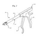
- FIG. 1is a perspective view of an embodiment of the invention
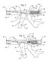
- FIG. 2is a cut-away side view of an embodiment of the invention in the non-actuated position
- FIG. 3is a cut-away side view of the embodiment of the invention shown in FIG. 2 in the actuated position;
- FIG. 4is a side view of the distal end of an embodiment of the invention wherein the pivoting action of the cutter beam is illustrated;
- FIG. 5is a perspective view of the linkage assembly of the distal end of the reamer tool shown in FIG. 4;
- FIG. 6is a top-down view of an embodiment of the cutter beam
- FIG. 7is a cut-away side view of a two handed embodiment of the invention in a non-actuated position
- FIG. 8is cut-away side view of a two handed embodiment of the invention in an actuated, cutting position
- FIG. 9is a side view of a serrated cutting beam
- FIG. 10is an end view of the serrated cutting beam of FIG. 9;
- FIG. 11is an enlarged side view of the end of the tool showing the cutting beam attachment
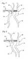
- FIG. 12is an anterior view of a spine showing a way in which the present invention may be used, without a guide tube over the tool;
- FIG. 13is a top view of a vertebral body showing one location where the tool can enter and provide reaming
- FIG. 14is a side view of a spine section showing an alternative manner in which the present invention may be used.
- the reamer toolindicated generally at 10 may be thought of as being comprised of three main portions: a proximal portion 12 , a middle portion 14 , and a distal portion 16 .
- the proximal or handle portion 12consists of a handle body 20 , a handle body lever 22 , a rack 24 and pinion 26 , a pinion handle lever 28 , a shoulder bolt 30 , and a biasing member or return spring 32 .
- the middle portion 14consists of a shaft tube 40 through which a drive rod 42 is longitudinally actuated. The drive rod 42 is engaged to the distal end 50 (as may be seen in FIG. 4) of the rack 24 .
- FIG. 2the reamer 10 is shown in the at rest or non-actuated position.
- the shoulder bolt 30is engaged to the proximal end 52 of the rack 24 .
- the biasing member or return spring 32is disposed about a bolt shaft 54 which extends proximally from the rack 24 passing through a return member 58 .
- the bolt shaft 54ends in an enlarged spring retaining portion 56 of the shoulder bolt 30 .
- the return spring 32is biasedly engaged between the spring retaining portion 56 of the shoulder bolt 30 and the return member 58 . This return spring exerts a force sufficient to keep the drive rod 42 extended distally.
- the force exerted by the return spring 32is overcome when the pinion handle lever 28 is engaged by the gripping action of the user previously described and shown in FIG. 3 .
- the levermay be actuated by an air cylinder, an electric solenoid or any other actuator means. Hand operated levers are shown which are less expensive and easier to clean.
- the proximal end 12contains only one handle body lever 22 and one pinion lever 28 .
- This embodimentis designed for single-handed operation.
- the reamer toolmay be designed for two-handed actuation.
- a two handed reamer tool 10has a the proximal end 12 having a handle body lever 22 which is equipped with opposing grip portions 90 and 92 , as well as a pinion lever 28 having opposed section 94 and 96 as well.
- the present embodiment of the reamer tool 10may be designed in such a manner that in order to rotate the cutter 60 an two handed grip of alternating action is required to actuate the opposing grips and lever sections 90 , 94 and 92 , 96 respectively.
- the distal portion or end 16 of the reamer 10contains the reamer head or cutting beam 60 .
- the beamhas a plurality of cutting surfaces 61 .
- the cutting bladesare located at the both ends 86 and 88 of the beam.
- the beam 60is pivotally connected to a handle body extension 62 by a lower pivot member 64 .
- the beam 60is also engaged to the a distal end 66 of the drive rod 42 via linkage assembly 68 .
- the linkage assembly 68comprises a pair of beam engagement projections 70 , as best shown in FIG. 5, which are disposed about the linkage tab 72 of the beam 60 , as best shown in FIG. 6 .
- a proximal pivot member 74passes through the linkage tab 72 and the beam engagement projections 70 .
- the linkage assembly 68also includes a pair of rod engagement projections 78 .
- a distal pivot member 76passes through the pair of rod engagement projections 78 as well as the distal end 66 of the drive rod 42 .
- the unique arrangement of the beam 60 to the drive rod 42 and extension 62 via the linkage assembly 68provides the reamer 10 with the ability to rotate the beam 60 about the lower pivot member 64 when the drive rod 42 is distally extended in the manner previously described.
- the cutting edges 61will cut into and abrade any tissue which is encountered by the moving cutting edges 61 .
- the cutting edges 61are positioned on both ends 86 and 88 of the beam 60 and may be on opposing sides of the beam 60 , such as may be seen in FIG. 4 .
- the cutting blades 61may be curved about the shape of a semi-circle, however, the blades 61 may also be provided with other shapes as desired.
- the entire perimeter 82 of the beam 60 , or a portion thereof,may include bladed portions 61 which extend beyond the semi-circle shape to form a “U” shape, such that cutting may occur along the lateral edges 63 of the perimeter 82 as well as the semi-circular ends 86 and 88 .
- the reamer 10may be configured to provide a variety of cutting options which will provide a smooth uniform resecting action as the beam 60 rotates back an forth as indicated by arrows 80 in FIG. 4 .
- the beam 60may include one or more backward cutting blades 65 , as is shown in FIG. 4, allowing cutting in both the forward and reverse directions.
- the reamer 10 of the present inventionmay be used in a number of different manners as may be recognized by those of skill in the art. When employed to debride an intervertebral disc, it may be understood that the reamer 10 may be used in the following manner.
- any appropriately sized standard drillmay be used to perforate the disc.
- the drillis guided in a direction that crosses the central portion of the disc, to a depth that comes close to, but does not penetrate the far side of the disc.
- the distal end 16 of the reamer 10is then placed into the disc to the full depth of the drilled hole.
- the reamer 10is oriented such that its beam 60 , with attached cutting blades 61 , is parallel to the transverse plane of the disc.
- the application of a manual compression forceforces the drive rod 42 in the distal direction.
- Thiscauses the beam 60 to rotate in an elliptical manner around the lower pivot member 64 .
- the beam 60may be pivotally displaced at least 90 degrees when the pinion lever 28 is actuated such as may be seen in FIG. 3 .
- the cutterwill typically provide more than 100 degrees of cutting. This motion causes the cutting blades 61 (and 63 ) to move against any intervening tissue, cleanly cutting that tissue.
- the return spring 32forces the drive rod 42 and the beam 60 back to their original and respective non-actuated positions when the pinion lever 28 is relaxed, such as may be seen in FIG. 2 .
- This proceduremay be used to remove the outer nucleus as well as the inner annulus of a spinal disk, leaving the outer annulus intact. Such a procedure is the goal of a partial disectomy.
- the reamer 10may then be reoriented 180 degrees, so that the opposite side of the disc can be debrided.
- the present inventionmay also utilize a variety of blade types to provide for different cutting and resecting characteristics.
- the cutter beam 60may be seen to employ one or more straight edge blades on the cutting edges 61 .
- one or more of the cutting edges 61may also have serrated teeth 90 such as may be seen in FIGS. 9 and 10.
- the cutter beam 60is maintained in a position such that the distal end 16 retains a profile substantially less than the distal end would have when in the actuated position such as is shown illustrated in phantom in FIG. 4 .
- the reduced profile of the non-actuated distal endis sufficiently small to allow insertion of the distal end 16 into a small space or cavity 100 such as is shown in FIG. 12 .
- the reamer tool 10is seen in use in merely one of a myriad of potential uses.
- the distal end 16 of the reamer tool 10may be inserted into an opening or cavity 100 of a spinal body 102 .
- the cutter beam 60is actuated, such as previously described, the cutting surfaces 61 abrade the surrounding tissue 104 to form a transverse cavity 106 .
- the reamer tool 10may be used to resect tissue from a spinal body 102 in the middle of a vertebral compression fracture, such as may best be seen in FIG. 14 .
- the tool 10along with any resected tissue is removed.
- the newly formed cavitymay then be filled with filler material such as bone cement and/or graft material.
- the cavity created by the toolwould tend to place the filler in a position where it could accumulate and develop pressure that would tend to elevate or re-expand (or reduce—in orthopedic terms—) the fracture, thereby forcing bone fragments into their pre-injury positions as illustrated in FIG. 14 .
- the various embodiments of the reamer tool 10 as described hereinmay also be used in a wide variety of other procedures.
- the present reamer toolmay be used for removing bone cement from the intramedullary canal of long bones during reconstructive procedures such as joint replacement.
- the toolmay also be useful for debriding cartilage from joints during arthoscopic procedures.
- Another usemay involve using the present reamer tool for certain types of joint arthrodesis, e.g. ankle, inter-tarsal, metatarsal-phalangeal, etc., wherein the tool is used in debriding and preparation of surfaces.
- reamer toolfor producing or sculpting channels for tendon insertion and/or reattachment, such as anterior curciate or rotator cuff repairs.
- the reamer toolmay be used in nasal or sinus surgery for sub-mucosal resections.
- the reamer toolmay also find use in certain gynecological procedures such as a dilation and curettage procedure (D&C).
- D&Cdilation and curettage procedure
- Yet another potential use for the present inventionwould be for fat immobilization during lipo-suction operations. In such a use the tool could be useful in freeing up fatty tissue to improve removal.
Landscapes
- Health & Medical Sciences (AREA)
- Surgery (AREA)
- Life Sciences & Earth Sciences (AREA)
- Biomedical Technology (AREA)
- Medical Informatics (AREA)
- Veterinary Medicine (AREA)
- Public Health (AREA)
- Engineering & Computer Science (AREA)
- General Health & Medical Sciences (AREA)
- Heart & Thoracic Surgery (AREA)
- Nuclear Medicine, Radiotherapy & Molecular Imaging (AREA)
- Molecular Biology (AREA)
- Animal Behavior & Ethology (AREA)
- Dentistry (AREA)
- Oral & Maxillofacial Surgery (AREA)
- Orthopedic Medicine & Surgery (AREA)
- Ophthalmology & Optometry (AREA)
- Surgical Instruments (AREA)
Abstract
Description
| U.S. Pat. No. | Inventor(s): | ||
| 6,200,320 B1 | Michelson | ||
| 6,142,997 | Michelson | ||
| 5,961,531 | Weber et al. | ||
| 5,766,177 | Lucas-Dean et al. | ||
| 5,653,713 | Michelson | ||
| 5,484,441 | Koros et al. | ||
| 5,451,227 | Michaelson | ||
| 5,312,407 | Carter | ||
| 5,026,375 | Linovitz et al. | ||
| 5,061,269 | Muller | ||
| 4,990,148 | Worrick, III et al. | ||
| 4,777,948 | Wright | ||
| 4,733,663 | Farely | ||
| 4,722,338 | Wright et al. | ||
| 3,902,498 | Niederer | ||
| 3,628,524 | Jamshidi | ||
| 2,984,241 | Carlson | ||
Claims (14)
Priority Applications (6)
| Application Number | Priority Date | Filing Date | Title |
|---|---|---|---|
| US09/827,202US6575978B2 (en) | 2001-04-05 | 2001-04-05 | Circumferential resecting reamer tool |
| PCT/US2002/010717WO2002096306A1 (en) | 2001-04-05 | 2002-04-03 | Circumferential resecting reamer tool |
| CA002441803ACA2441803A1 (en) | 2001-04-05 | 2002-04-03 | Circumferential resecting reamer tool |
| KR1020037013008AKR100867759B1 (en) | 2001-04-05 | 2002-04-03 | Peripheral Cutting Reamer Tool |
| JP2002592824AJP2004527343A (en) | 2001-04-05 | 2002-04-03 | Circumferential resection reamer |
| EP02741660AEP1372496A1 (en) | 2001-04-05 | 2002-04-03 | Circumferential resecting reamer tool |
Applications Claiming Priority (1)
| Application Number | Priority Date | Filing Date | Title |
|---|---|---|---|
| US09/827,202US6575978B2 (en) | 2001-04-05 | 2001-04-05 | Circumferential resecting reamer tool |
Publications (2)
| Publication Number | Publication Date |
|---|---|
| US20020173813A1 US20020173813A1 (en) | 2002-11-21 |
| US6575978B2true US6575978B2 (en) | 2003-06-10 |
Family
ID=25248569
Family Applications (1)
| Application Number | Title | Priority Date | Filing Date |
|---|---|---|---|
| US09/827,202Expired - Fee RelatedUS6575978B2 (en) | 2001-04-05 | 2001-04-05 | Circumferential resecting reamer tool |
Country Status (6)
| Country | Link |
|---|---|
| US (1) | US6575978B2 (en) |
| EP (1) | EP1372496A1 (en) |
| JP (1) | JP2004527343A (en) |
| KR (1) | KR100867759B1 (en) |
| CA (1) | CA2441803A1 (en) |
| WO (1) | WO2002096306A1 (en) |
Cited By (64)
| Publication number | Priority date | Publication date | Assignee | Title |
|---|---|---|---|---|
| US20020022856A1 (en)* | 2000-08-14 | 2002-02-21 | Wesley Johnson | Transverse cavity device and method |
| US20020193799A1 (en)* | 2001-06-18 | 2002-12-19 | Chappuis James L. | Surgical instrumentation and method for forming a passage in bone having an enlarged cross-sectional portion |
| US20040092943A1 (en)* | 2002-01-14 | 2004-05-13 | Buttermann Glenn Robin | Apparatus and method for performing spinal surgery |
| US20050113924A1 (en)* | 2003-08-07 | 2005-05-26 | Dynamic Spine, Inc. | Apparatus and method for performing spinal surgery |
| US20050261692A1 (en)* | 2004-05-21 | 2005-11-24 | Scimed Life Systems, Inc. | Articulating tissue removal probe and methods of using the same |
| US20060116689A1 (en)* | 2004-06-16 | 2006-06-01 | Sdgi Holdings, Inc. | Surgical instrumentation and method for treatment of a spinal structure |
| US20060155289A1 (en)* | 2004-12-10 | 2006-07-13 | Stryker Trauma Gmbh | Apparatus for reaming bone cavities |
| US20070055259A1 (en)* | 2005-08-17 | 2007-03-08 | Norton Britt K | Apparatus and methods for removal of intervertebral disc tissues |
| US20070118142A1 (en)* | 2005-11-18 | 2007-05-24 | Krueger John A | Device, system and method for delivering a curable material into bone |
| US20070142843A1 (en)* | 2005-12-21 | 2007-06-21 | Justin Dye | Articulated delivery instrument |
| US20070142842A1 (en)* | 2005-11-18 | 2007-06-21 | Krueger John A | Device, system and method for delivering a curable material into bone |
| US20070162062A1 (en)* | 2005-12-08 | 2007-07-12 | Norton Britt K | Reciprocating apparatus and methods for removal of intervertebral disc tissues |
| US20070198013A1 (en)* | 2000-08-11 | 2007-08-23 | Foley Kevin T | Surgical instrumentation and method for treatment of the spine |
| US20070225726A1 (en)* | 2006-03-23 | 2007-09-27 | Justin Dye | Instruments for delivering spinal implants |
| US20080065219A1 (en)* | 2006-09-08 | 2008-03-13 | Justin Dye | Offset radius lordosis |
| US20080077150A1 (en)* | 2006-09-22 | 2008-03-27 | Linh Nguyen | Steerable rasp/trial member inserter and method of use |
| US20080086133A1 (en)* | 2003-05-16 | 2008-04-10 | Spineology | Expandable porous mesh bag device and methods of use for reduction, filling, fixation and supporting of bone |
| US20080139995A1 (en)* | 2006-12-07 | 2008-06-12 | Tyco Healthcare Group Lp | Bipolar tissue debrider and method |
| US20090054898A1 (en)* | 2007-03-26 | 2009-02-26 | Joe Gleason | Articulating Shaper |
| US20090318940A1 (en)* | 2004-03-16 | 2009-12-24 | Macroplata Systems, Llc | Endoluminal treatment method and associated surgical assembly including tissue occlusion device |
| US7641664B2 (en) | 2004-02-12 | 2010-01-05 | Warsaw Orthopedic, Inc. | Surgical instrumentation and method for treatment of a spinal structure |
| USD613407S1 (en)* | 2008-08-05 | 2010-04-06 | Atlas Spine, Inc. | Mechanical rasp |
| US7811291B2 (en) | 2007-11-16 | 2010-10-12 | Osseon Therapeutics, Inc. | Closed vertebroplasty bone cement injection system |
| US7909873B2 (en) | 2006-12-15 | 2011-03-22 | Soteira, Inc. | Delivery apparatus and methods for vertebrostenting |
| US7931689B2 (en) | 2000-02-28 | 2011-04-26 | Spineology Inc. | Method and apparatus for treating a vertebral body |
| US20110190832A1 (en)* | 2010-01-20 | 2011-08-04 | Kyle Taylor | Apparatus and methods for bone access and cavity preparation |
| USD643115S1 (en)* | 2010-06-04 | 2011-08-09 | Entrigue Surgical, Inc. | Insertion device |
| US20110218626A1 (en)* | 2010-03-08 | 2011-09-08 | Krinke Todd A | Apparatus and methods for securing a bone implant |
| US8277506B2 (en) | 2008-06-24 | 2012-10-02 | Carefusion 2200, Inc. | Method and structure for stabilizing a vertebral body |
| USD669168S1 (en) | 2005-11-18 | 2012-10-16 | Carefusion 2200, Inc. | Vertebral augmentation needle |
| US20130109926A1 (en)* | 2010-04-26 | 2013-05-02 | Macroplata, Inc. | Apparatus and method for effecting at least one anatomical structure |
| US8663227B2 (en) | 2011-12-03 | 2014-03-04 | Ouroboros Medical, Inc. | Single-unit cutting head systems for safe removal of nucleus pulposus tissue |
| US8690884B2 (en) | 2005-11-18 | 2014-04-08 | Carefusion 2200, Inc. | Multistate-curvature device and method for delivering a curable material into bone |
| US8827981B2 (en) | 2007-11-16 | 2014-09-09 | Osseon Llc | Steerable vertebroplasty system with cavity creation element |
| US20140257112A1 (en)* | 2013-03-07 | 2014-09-11 | Marc Evan Siegel | Gynecological scope and morcellation systems and devices |
| US20150080896A1 (en) | 2013-07-19 | 2015-03-19 | Ouroboros Medical, Inc. | Anti-clogging device for a vacuum-assisted, tissue removal system |
| US9011317B2 (en) | 2010-04-26 | 2015-04-21 | Covidien Lp | Gentle hemorrhoid treatment offering a substantially painless healing |
| US9168078B2 (en) | 2009-11-10 | 2015-10-27 | Carefusion 2200, Inc. | Apparatus and method for stylet-guided vertebral augmentation |
| US9192397B2 (en) | 2006-12-15 | 2015-11-24 | Gmedelaware 2 Llc | Devices and methods for fracture reduction |
| US9480485B2 (en) | 2006-12-15 | 2016-11-01 | Globus Medical, Inc. | Devices and methods for vertebrostenting |
| US9510885B2 (en) | 2007-11-16 | 2016-12-06 | Osseon Llc | Steerable and curvable cavity creation system |
| US9517093B2 (en) | 2008-01-14 | 2016-12-13 | Conventus Orthopaedics, Inc. | Apparatus and methods for fracture repair |
| US9730739B2 (en) | 2010-01-15 | 2017-08-15 | Conventus Orthopaedics, Inc. | Rotary-rigid orthopaedic rod |
| US10022132B2 (en) | 2013-12-12 | 2018-07-17 | Conventus Orthopaedics, Inc. | Tissue displacement tools and methods |
| US10292714B2 (en)* | 2016-11-08 | 2019-05-21 | Tautog, LLC | Powered surgical device |
| US10441295B2 (en) | 2013-10-15 | 2019-10-15 | Stryker Corporation | Device for creating a void space in a living tissue, the device including a handle with a control knob that can be set regardless of the orientation of the handle |
| US10441336B2 (en) | 2017-06-14 | 2019-10-15 | Osteoagra Llc | Stabilization of vertebral bodies with bone particle slurry |
| US10463380B2 (en) | 2016-12-09 | 2019-11-05 | Dfine, Inc. | Medical devices for treating hard tissues and related methods |
| US10478241B2 (en) | 2016-10-27 | 2019-11-19 | Merit Medical Systems, Inc. | Articulating osteotome with cement delivery channel |
| US10624652B2 (en) | 2010-04-29 | 2020-04-21 | Dfine, Inc. | System for use in treatment of vertebral fractures |
| US10660656B2 (en) | 2017-01-06 | 2020-05-26 | Dfine, Inc. | Osteotome with a distal portion for simultaneous advancement and articulation |
| US10918426B2 (en) | 2017-07-04 | 2021-02-16 | Conventus Orthopaedics, Inc. | Apparatus and methods for treatment of a bone |
| US20210085359A1 (en)* | 2019-09-20 | 2021-03-25 | Spineology Inc. | Articulating curette |
| US11026744B2 (en) | 2016-11-28 | 2021-06-08 | Dfine, Inc. | Tumor ablation devices and related methods |
| US11197681B2 (en) | 2009-05-20 | 2021-12-14 | Merit Medical Systems, Inc. | Steerable curvable vertebroplasty drill |
| US11234716B2 (en) | 2019-02-22 | 2022-02-01 | Globus Medical, Inc. | Methods and apparatus for performing discectomy |
| US11510723B2 (en) | 2018-11-08 | 2022-11-29 | Dfine, Inc. | Tumor ablation device and related systems and methods |
| US11596419B2 (en) | 2017-03-09 | 2023-03-07 | Flower Orthopedics Corporation | Plating depth gauge and countersink instrument |
| US20230157710A1 (en)* | 2021-11-23 | 2023-05-25 | Life Spine, Inc. | Articulating curette for decorticating a vertebral endplate via a cannula |
| US11849986B2 (en) | 2019-04-24 | 2023-12-26 | Stryker Corporation | Systems and methods for off-axis augmentation of a vertebral body |
| US11986229B2 (en) | 2019-09-18 | 2024-05-21 | Merit Medical Systems, Inc. | Osteotome with inflatable portion and multiwire articulation |
| US12102348B2 (en) | 2016-09-07 | 2024-10-01 | Vertos Medical, Inc. | Percutaneous lateral recess resection methods and instruments |
| US12102367B2 (en) | 2017-06-14 | 2024-10-01 | Osteoagra Llc | Method, composition, and apparatus for stabilization of vertebral bodies |
| US12324572B2 (en) | 2022-06-16 | 2025-06-10 | Vertos Medical, Inc. | Integrated instrument assembly |
Families Citing this family (42)
| Publication number | Priority date | Publication date | Assignee | Title |
|---|---|---|---|---|
| US7922739B2 (en)* | 2003-03-28 | 2011-04-12 | Downey Earl C | Surgical instrument with trigger control |
| US6923813B2 (en)* | 2003-09-03 | 2005-08-02 | Kyphon Inc. | Devices for creating voids in interior body regions and related methods |
| US8123757B2 (en)* | 2003-12-31 | 2012-02-28 | Depuy Spine, Inc. | Inserter instrument and implant clip |
| US7846183B2 (en) | 2004-02-06 | 2010-12-07 | Spinal Elements, Inc. | Vertebral facet joint prosthesis and method of fixation |
| US20050192592A1 (en)* | 2004-02-27 | 2005-09-01 | Cook Urological Incorporated | Self-tensioning handle for endoscopic device |
| US9504583B2 (en) | 2004-06-10 | 2016-11-29 | Spinal Elements, Inc. | Implant and method for facet immobilization |
| US8080004B2 (en)* | 2005-10-26 | 2011-12-20 | Earl Downey | Laparoscopic surgical instrument |
| US7479752B2 (en)* | 2006-06-21 | 2009-01-20 | Ethicon-Endo Surgery, Inc. | Rotation actuator for endoscopic devices |
| EP2813190B1 (en) | 2007-02-22 | 2017-04-26 | Spinal Elements, Inc. | Vertebral facet joint drill |
| US8992533B2 (en) | 2007-02-22 | 2015-03-31 | Spinal Elements, Inc. | Vertebral facet joint drill and method of use |
| US8579910B2 (en) | 2007-05-18 | 2013-11-12 | DePuy Synthes Products, LLC | Insertion blade assembly and method of use |
| US20090299141A1 (en)* | 2008-04-25 | 2009-12-03 | Downey Earl C | Laparoscopic Surgical Instrument |
| KR100897928B1 (en)* | 2008-12-23 | 2009-05-18 | 박윤관 | Elevation device for spinal condyle extension |
| US8906033B2 (en) | 2009-03-30 | 2014-12-09 | DePuy Synthes Products, LLC | Cervical motion disc inserter |
| US9271765B2 (en) | 2011-02-24 | 2016-03-01 | Spinal Elements, Inc. | Vertebral facet joint fusion implant and method for fusion |
| US8740949B2 (en) | 2011-02-24 | 2014-06-03 | Spinal Elements, Inc. | Methods and apparatus for stabilizing bone |
| USD724733S1 (en) | 2011-02-24 | 2015-03-17 | Spinal Elements, Inc. | Interbody bone implant |
| US20120271313A1 (en)* | 2011-04-21 | 2012-10-25 | Warsaw Orthopedic, Inc. | Long scraper tool for discectomy |
| USD739935S1 (en) | 2011-10-26 | 2015-09-29 | Spinal Elements, Inc. | Interbody bone implant |
| USD765853S1 (en) | 2013-03-14 | 2016-09-06 | Spinal Elements, Inc. | Flexible elongate member with a portion configured to receive a bone anchor |
| US9480574B2 (en) | 2013-03-14 | 2016-11-01 | Benvenue Medical, Inc. | Spinal fusion implants and devices and methods for deploying such implants |
| US9421044B2 (en) | 2013-03-14 | 2016-08-23 | Spinal Elements, Inc. | Apparatus for bone stabilization and distraction and methods of use |
| US9820784B2 (en) | 2013-03-14 | 2017-11-21 | Spinal Elements, Inc. | Apparatus for spinal fixation and methods of use |
| US9839450B2 (en) | 2013-09-27 | 2017-12-12 | Spinal Elements, Inc. | Device and method for reinforcement of a facet |
| US9456855B2 (en) | 2013-09-27 | 2016-10-04 | Spinal Elements, Inc. | Method of placing an implant between bone portions |
| US10314605B2 (en)* | 2014-07-08 | 2019-06-11 | Benvenue Medical, Inc. | Apparatus and methods for disrupting intervertebral disc tissue |
| CN104055558A (en)* | 2014-07-10 | 2014-09-24 | 苏州吉美瑞医疗器械有限公司 | Vertebra restoration pincers held with one hand |
| US9662123B2 (en)* | 2014-07-31 | 2017-05-30 | Amendia, Inc. | Vertical cutter and method of use |
| US11478275B2 (en) | 2014-09-17 | 2022-10-25 | Spinal Elements, Inc. | Flexible fastening band connector |
| AU2016212009C1 (en) | 2015-01-27 | 2021-02-25 | Spinal Elements, Inc. | Facet joint implant |
| EP3357437A1 (en) | 2017-02-01 | 2018-08-08 | Spinal Stabilization Technologies Ltd | A surgical cutting instrument |
| WO2019148083A1 (en) | 2018-01-29 | 2019-08-01 | Benvenue Medical, Inc. | Minimally invasive interbody fusion |
| WO2019178575A1 (en) | 2018-03-16 | 2019-09-19 | Benvenue Medical, Inc. | Articulated instrumentation and methods of using the same |
| US11457959B2 (en) | 2019-05-22 | 2022-10-04 | Spinal Elements, Inc. | Bone tie and bone tie inserter |
| BR112021022695A2 (en) | 2019-05-22 | 2021-12-28 | Spinal Elements Inc | Bone tethering and bone tethering inserter |
| CN110693572A (en)* | 2019-10-17 | 2020-01-17 | 徐州市中心医院 | A universal multi-angle anti-nucleus residual exploration curette under spinal endoscopy |
| CN110811759A (en)* | 2019-11-28 | 2020-02-21 | 四川大学华西医院 | A cartilage extractor for plastic surgery |
| WO2021163313A1 (en) | 2020-02-14 | 2021-08-19 | Spinal Elements, Inc. | Bone tie methods |
| CN118042995A (en)* | 2021-09-22 | 2024-05-14 | 脊柱外科策略有限公司 | Surgical instrument |
| US12369952B2 (en)* | 2021-12-10 | 2025-07-29 | Spinal Elements, Inc. | Bone tie and portal |
| CN116250896B (en)* | 2023-03-03 | 2024-08-06 | 瑞镧医疗科技(上海)有限公司 | Tissue cutting device |
| DE102023122460A1 (en)* | 2023-08-22 | 2025-02-27 | Aesculap Ag | Surgical pistol grip and surgical instrument with pistol grip |
Citations (17)
| Publication number | Priority date | Publication date | Assignee | Title |
|---|---|---|---|---|
| DE8712271U1 (en) | 1987-09-10 | 1988-01-21 | Jakoubek, Franz, 7201 Emmingen-Liptingen | Biopsy and foreign body forceps |
| DE3741493A1 (en) | 1987-12-08 | 1989-06-22 | Roland Man Druckmasch | Supporting element for holding two adjacent vertebrae |
| US5112346A (en)* | 1989-06-08 | 1992-05-12 | Richard Wolf Gmbh | Retrograde cutting hook punch |
| US5571189A (en) | 1994-05-20 | 1996-11-05 | Kuslich; Stephen D. | Expandable fabric implant for stabilizing the spinal motion segment |
| US5571131A (en)* | 1995-06-07 | 1996-11-05 | Smith & Nephew Endoscopy, Inc. | Back biting punch |
| US5649947A (en)* | 1990-11-09 | 1997-07-22 | Arthrotek, Inc. | Surgical instrument |
| US5755979A (en) | 1994-07-27 | 1998-05-26 | Texas Instruments Incorporated | Application of semiconductor IC fabrication techniques to the manufacturing of a conditioning head for pad conditioning during chemical-mechanical polish |
| US5817119A (en)* | 1993-07-21 | 1998-10-06 | Charles H. Klieman | Surgical instrument for endoscopic and general surgery |
| US5840044A (en)* | 1993-09-30 | 1998-11-24 | Boston Scientific Corporation | Multiple biopsy sampling forceps |
| WO1999002108A1 (en) | 1997-07-10 | 1999-01-21 | Douglas Wardlaw | Intervertebral disc nucleus prosthesis |
| US5913866A (en)* | 1997-06-19 | 1999-06-22 | Cardiothoracic Systems, Inc. | Devices and methods for harvesting vascular conduits |
| US5928239A (en) | 1998-03-16 | 1999-07-27 | University Of Washington | Percutaneous surgical cavitation device and method |
| US5972015A (en) | 1997-08-15 | 1999-10-26 | Kyphon Inc. | Expandable, asymetric structures for deployment in interior body regions |
| US5984939A (en)* | 1989-12-05 | 1999-11-16 | Yoon; Inbae | Multifunctional grasping instrument with cutting member and operating channel for use in endoscopic and non-endoscopic procedures |
| DE19852682A1 (en) | 1998-11-16 | 2000-05-25 | Robert Mueller | Surgical instrument has guide element, operating unit, stationary and movable branch elements, compression spring, stop, slide piece and angular adjustment |
| US6127597A (en) | 1997-03-07 | 2000-10-03 | Discotech N.V. | Systems for percutaneous bone and spinal stabilization, fixation and repair |
| WO2000067650A1 (en) | 1999-05-07 | 2000-11-16 | University Of Virginia Patent Foundation | Method and system for fusing a spinal region |
Family Cites Families (1)
| Publication number | Priority date | Publication date | Assignee | Title |
|---|---|---|---|---|
| DE2808911C2 (en)* | 1978-03-02 | 1979-11-08 | B. Braun Melsungen Ag, 3508 Melsungen | Punch to remove bone and cartilage |
- 2001
- 2001-04-05USUS09/827,202patent/US6575978B2/ennot_activeExpired - Fee Related
- 2002
- 2002-04-03JPJP2002592824Apatent/JP2004527343A/enactivePending
- 2002-04-03KRKR1020037013008Apatent/KR100867759B1/ennot_activeExpired - Fee Related
- 2002-04-03WOPCT/US2002/010717patent/WO2002096306A1/enactiveApplication Filing
- 2002-04-03EPEP02741660Apatent/EP1372496A1/ennot_activeWithdrawn
- 2002-04-03CACA002441803Apatent/CA2441803A1/ennot_activeAbandoned
Patent Citations (17)
| Publication number | Priority date | Publication date | Assignee | Title |
|---|---|---|---|---|
| DE8712271U1 (en) | 1987-09-10 | 1988-01-21 | Jakoubek, Franz, 7201 Emmingen-Liptingen | Biopsy and foreign body forceps |
| DE3741493A1 (en) | 1987-12-08 | 1989-06-22 | Roland Man Druckmasch | Supporting element for holding two adjacent vertebrae |
| US5112346A (en)* | 1989-06-08 | 1992-05-12 | Richard Wolf Gmbh | Retrograde cutting hook punch |
| US5984939A (en)* | 1989-12-05 | 1999-11-16 | Yoon; Inbae | Multifunctional grasping instrument with cutting member and operating channel for use in endoscopic and non-endoscopic procedures |
| US5649947A (en)* | 1990-11-09 | 1997-07-22 | Arthrotek, Inc. | Surgical instrument |
| US5817119A (en)* | 1993-07-21 | 1998-10-06 | Charles H. Klieman | Surgical instrument for endoscopic and general surgery |
| US5840044A (en)* | 1993-09-30 | 1998-11-24 | Boston Scientific Corporation | Multiple biopsy sampling forceps |
| US5571189A (en) | 1994-05-20 | 1996-11-05 | Kuslich; Stephen D. | Expandable fabric implant for stabilizing the spinal motion segment |
| US5755979A (en) | 1994-07-27 | 1998-05-26 | Texas Instruments Incorporated | Application of semiconductor IC fabrication techniques to the manufacturing of a conditioning head for pad conditioning during chemical-mechanical polish |
| US5571131A (en)* | 1995-06-07 | 1996-11-05 | Smith & Nephew Endoscopy, Inc. | Back biting punch |
| US6127597A (en) | 1997-03-07 | 2000-10-03 | Discotech N.V. | Systems for percutaneous bone and spinal stabilization, fixation and repair |
| US5913866A (en)* | 1997-06-19 | 1999-06-22 | Cardiothoracic Systems, Inc. | Devices and methods for harvesting vascular conduits |
| WO1999002108A1 (en) | 1997-07-10 | 1999-01-21 | Douglas Wardlaw | Intervertebral disc nucleus prosthesis |
| US5972015A (en) | 1997-08-15 | 1999-10-26 | Kyphon Inc. | Expandable, asymetric structures for deployment in interior body regions |
| US5928239A (en) | 1998-03-16 | 1999-07-27 | University Of Washington | Percutaneous surgical cavitation device and method |
| DE19852682A1 (en) | 1998-11-16 | 2000-05-25 | Robert Mueller | Surgical instrument has guide element, operating unit, stationary and movable branch elements, compression spring, stop, slide piece and angular adjustment |
| WO2000067650A1 (en) | 1999-05-07 | 2000-11-16 | University Of Virginia Patent Foundation | Method and system for fusing a spinal region |
Cited By (146)
| Publication number | Priority date | Publication date | Assignee | Title |
|---|---|---|---|---|
| US7931689B2 (en) | 2000-02-28 | 2011-04-26 | Spineology Inc. | Method and apparatus for treating a vertebral body |
| US20070198013A1 (en)* | 2000-08-11 | 2007-08-23 | Foley Kevin T | Surgical instrumentation and method for treatment of the spine |
| US20090187190A1 (en)* | 2000-08-14 | 2009-07-23 | Spine Wave, Inc. | Transverse Cavity Device and Method |
| US20070162032A1 (en)* | 2000-08-14 | 2007-07-12 | Spine Wave, Inc. | Transverse Cavity Device and Method |
| US20020022856A1 (en)* | 2000-08-14 | 2002-02-21 | Wesley Johnson | Transverse cavity device and method |
| US7234468B2 (en) | 2000-08-14 | 2007-06-26 | Spine Wave, Inc. | Transverse cavity device and method |
| US20050182413A1 (en)* | 2000-08-14 | 2005-08-18 | Wesley Johnson | Transverse cavity device and method |
| US20050182412A1 (en)* | 2000-08-14 | 2005-08-18 | Wesley Johnson | Transverse cavity device and method |
| US7815643B2 (en) | 2000-08-14 | 2010-10-19 | Spine Wave, Inc. | Transverse cavity device and method |
| US7114501B2 (en) | 2000-08-14 | 2006-10-03 | Spine Wave, Inc. | Transverse cavity device and method |
| US6814734B2 (en)* | 2001-06-18 | 2004-11-09 | Sdgi Holdings, Inc, | Surgical instrumentation and method for forming a passage in bone having an enlarged cross-sectional portion |
| US7749225B2 (en) | 2001-06-18 | 2010-07-06 | Warsaw Orthopedic, Inc. | Surgical instrumentation and method for forming a passage in bone having an enlarged cross-sectional portion |
| US20050033303A1 (en)* | 2001-06-18 | 2005-02-10 | Chappuis James L. | Surgical instrumentation and method for forming a passage in bone having an enlarged cross-sectional portion |
| US20020193799A1 (en)* | 2001-06-18 | 2002-12-19 | Chappuis James L. | Surgical instrumentation and method for forming a passage in bone having an enlarged cross-sectional portion |
| US20100185204A1 (en)* | 2002-01-14 | 2010-07-22 | Dynamic Spine, Inc. | Apparatus and method for performing spinal surgery |
| US7303565B2 (en) | 2002-01-14 | 2007-12-04 | Dynamic Spine, Inc. | Apparatus and method for performing spinal surgery |
| US20040092943A1 (en)* | 2002-01-14 | 2004-05-13 | Buttermann Glenn Robin | Apparatus and method for performing spinal surgery |
| US20080086133A1 (en)* | 2003-05-16 | 2008-04-10 | Spineology | Expandable porous mesh bag device and methods of use for reduction, filling, fixation and supporting of bone |
| US20050113924A1 (en)* | 2003-08-07 | 2005-05-26 | Dynamic Spine, Inc. | Apparatus and method for performing spinal surgery |
| US8057549B2 (en) | 2003-08-07 | 2011-11-15 | Dynamic Spine, Inc. | Apparatus and method for performing spinal surgery |
| US20080215153A1 (en)* | 2003-08-07 | 2008-09-04 | Buttermann Glenn Robin | Apparatus and method for performing spinal surgery |
| US8034088B2 (en) | 2004-02-12 | 2011-10-11 | Warsaw Orthopedic, Inc. | Surgical instrumentation and method for treatment of a spinal structure |
| US7641664B2 (en) | 2004-02-12 | 2010-01-05 | Warsaw Orthopedic, Inc. | Surgical instrumentation and method for treatment of a spinal structure |
| US20100076445A1 (en)* | 2004-02-12 | 2010-03-25 | Warsaw Orthopedic, Inc. | Surgical Instrumentation and Method for Treatment of a Spinal Structure |
| US8715166B2 (en) | 2004-03-16 | 2014-05-06 | Macroplata Inc. | Gentle method of treating a hemorrhoid |
| US9867633B2 (en) | 2004-03-16 | 2018-01-16 | Covidien Lp | Endoluminal treatment method and associated surgical assembly including tissue occlusion device |
| US20090318940A1 (en)* | 2004-03-16 | 2009-12-24 | Macroplata Systems, Llc | Endoluminal treatment method and associated surgical assembly including tissue occlusion device |
| US10245061B2 (en) | 2004-03-16 | 2019-04-02 | Covidien Lp | Treatment method including tissue occlusion device |
| US20050261692A1 (en)* | 2004-05-21 | 2005-11-24 | Scimed Life Systems, Inc. | Articulating tissue removal probe and methods of using the same |
| US20060116689A1 (en)* | 2004-06-16 | 2006-06-01 | Sdgi Holdings, Inc. | Surgical instrumentation and method for treatment of a spinal structure |
| US20060155289A1 (en)* | 2004-12-10 | 2006-07-13 | Stryker Trauma Gmbh | Apparatus for reaming bone cavities |
| US20070055259A1 (en)* | 2005-08-17 | 2007-03-08 | Norton Britt K | Apparatus and methods for removal of intervertebral disc tissues |
| US8690884B2 (en) | 2005-11-18 | 2014-04-08 | Carefusion 2200, Inc. | Multistate-curvature device and method for delivering a curable material into bone |
| US10314633B2 (en) | 2005-11-18 | 2019-06-11 | Stryker Corporation | Shape memory device with temperature-dependent deflectable segment and methods of positioning a shape memory device within a bone structure |
| US20100087828A1 (en)* | 2005-11-18 | 2010-04-08 | Krueger John A | Device, system and method for delivering a curable material into bone |
| US7713273B2 (en) | 2005-11-18 | 2010-05-11 | Carefusion 2200, Inc. | Device, system and method for delivering a curable material into bone |
| US20100121336A1 (en)* | 2005-11-18 | 2010-05-13 | Linderman Evan D | Device, system, and method for forming a cavity in and delivering a curable material into bone |
| US20070142842A1 (en)* | 2005-11-18 | 2007-06-21 | Krueger John A | Device, system and method for delivering a curable material into bone |
| US9358059B2 (en) | 2005-11-18 | 2016-06-07 | Carefusion 2200, Inc. | Device and method for delivering a curable material into bone |
| US9795429B2 (en) | 2005-11-18 | 2017-10-24 | Stryker Corporation | Device and method for removing bodily material |
| US7799035B2 (en) | 2005-11-18 | 2010-09-21 | Carefusion 2200, Inc. | Device, system and method for delivering a curable material into bone |
| US8529576B2 (en) | 2005-11-18 | 2013-09-10 | Carefusion 2200, Inc. | Device, system and method for delivering a curable material into bone |
| US20070118142A1 (en)* | 2005-11-18 | 2007-05-24 | Krueger John A | Device, system and method for delivering a curable material into bone |
| USD669168S1 (en) | 2005-11-18 | 2012-10-16 | Carefusion 2200, Inc. | Vertebral augmentation needle |
| US8128633B2 (en) | 2005-11-18 | 2012-03-06 | Carefusion 2200, Inc. | Device, system, and method for forming a cavity in and delivering a curable material into bone |
| US20070162062A1 (en)* | 2005-12-08 | 2007-07-12 | Norton Britt K | Reciprocating apparatus and methods for removal of intervertebral disc tissues |
| US7988695B2 (en) | 2005-12-21 | 2011-08-02 | Theken Spine, Llc | Articulated delivery instrument |
| US20070142843A1 (en)* | 2005-12-21 | 2007-06-21 | Justin Dye | Articulated delivery instrument |
| US20070225726A1 (en)* | 2006-03-23 | 2007-09-27 | Justin Dye | Instruments for delivering spinal implants |
| US7976549B2 (en) | 2006-03-23 | 2011-07-12 | Theken Spine, Llc | Instruments for delivering spinal implants |
| US8506636B2 (en) | 2006-09-08 | 2013-08-13 | Theken Spine, Llc | Offset radius lordosis |
| US20080065219A1 (en)* | 2006-09-08 | 2008-03-13 | Justin Dye | Offset radius lordosis |
| US20080077150A1 (en)* | 2006-09-22 | 2008-03-27 | Linh Nguyen | Steerable rasp/trial member inserter and method of use |
| US7682360B2 (en) | 2006-12-07 | 2010-03-23 | Tyco Healthcare Group Lp | Bipolar tissue debrider and method |
| US7909822B2 (en) | 2006-12-07 | 2011-03-22 | Tyco Healthcare Group Lp | Bipolar tissue debrider and method |
| US20080139995A1 (en)* | 2006-12-07 | 2008-06-12 | Tyco Healthcare Group Lp | Bipolar tissue debrider and method |
| US20100160912A1 (en)* | 2006-12-07 | 2010-06-24 | Tyco Healthcare Group Lp | Bipolar Tissue Debrider and Method |
| US9192397B2 (en) | 2006-12-15 | 2015-11-24 | Gmedelaware 2 Llc | Devices and methods for fracture reduction |
| US7909873B2 (en) | 2006-12-15 | 2011-03-22 | Soteira, Inc. | Delivery apparatus and methods for vertebrostenting |
| US9237916B2 (en) | 2006-12-15 | 2016-01-19 | Gmedeleware 2 Llc | Devices and methods for vertebrostenting |
| US9480485B2 (en) | 2006-12-15 | 2016-11-01 | Globus Medical, Inc. | Devices and methods for vertebrostenting |
| US8623025B2 (en) | 2006-12-15 | 2014-01-07 | Gmedelaware 2 Llc | Delivery apparatus and methods for vertebrostenting |
| US20090054898A1 (en)* | 2007-03-26 | 2009-02-26 | Joe Gleason | Articulating Shaper |
| US9510885B2 (en) | 2007-11-16 | 2016-12-06 | Osseon Llc | Steerable and curvable cavity creation system |
| US8827981B2 (en) | 2007-11-16 | 2014-09-09 | Osseon Llc | Steerable vertebroplasty system with cavity creation element |
| US7811291B2 (en) | 2007-11-16 | 2010-10-12 | Osseon Therapeutics, Inc. | Closed vertebroplasty bone cement injection system |
| US7842041B2 (en) | 2007-11-16 | 2010-11-30 | Osseon Therapeutics, Inc. | Steerable vertebroplasty system |
| US9788870B2 (en) | 2008-01-14 | 2017-10-17 | Conventus Orthopaedics, Inc. | Apparatus and methods for fracture repair |
| US11399878B2 (en) | 2008-01-14 | 2022-08-02 | Conventus Orthopaedics, Inc. | Apparatus and methods for fracture repair |
| US9517093B2 (en) | 2008-01-14 | 2016-12-13 | Conventus Orthopaedics, Inc. | Apparatus and methods for fracture repair |
| US10603087B2 (en) | 2008-01-14 | 2020-03-31 | Conventus Orthopaedics, Inc. | Apparatus and methods for fracture repair |
| US9687255B2 (en) | 2008-06-17 | 2017-06-27 | Globus Medical, Inc. | Device and methods for fracture reduction |
| US10588646B2 (en) | 2008-06-17 | 2020-03-17 | Globus Medical, Inc. | Devices and methods for fracture reduction |
| US8277506B2 (en) | 2008-06-24 | 2012-10-02 | Carefusion 2200, Inc. | Method and structure for stabilizing a vertebral body |
| USD613407S1 (en)* | 2008-08-05 | 2010-04-06 | Atlas Spine, Inc. | Mechanical rasp |
| US11197681B2 (en) | 2009-05-20 | 2021-12-14 | Merit Medical Systems, Inc. | Steerable curvable vertebroplasty drill |
| US9168078B2 (en) | 2009-11-10 | 2015-10-27 | Carefusion 2200, Inc. | Apparatus and method for stylet-guided vertebral augmentation |
| US10022173B2 (en) | 2009-11-10 | 2018-07-17 | Stryker Corporation | Systems and methods for vertebral or other bone structure height restoration and stabilization |
| US9526551B2 (en) | 2009-11-10 | 2016-12-27 | Stryker Corporation | Apparatus and method for stylet-guided vertebral augmentation |
| US11666366B2 (en) | 2009-11-10 | 2023-06-06 | Stryker Corporation | Systems and methods for vertebral or other bone structure height restoration and stabilization |
| US9907595B2 (en) | 2009-11-10 | 2018-03-06 | Stryker Corporation | Systems and methods for vertebral or other bone structure height restoration and stabilization |
| US10905487B2 (en) | 2009-11-10 | 2021-02-02 | Stryker Corporation | Systems and methods for vertebral or other bone structure height restoration and stabilization |
| US9730739B2 (en) | 2010-01-15 | 2017-08-15 | Conventus Orthopaedics, Inc. | Rotary-rigid orthopaedic rod |
| US9848889B2 (en) | 2010-01-20 | 2017-12-26 | Conventus Orthopaedics, Inc. | Apparatus and methods for bone access and cavity preparation |
| US20110190832A1 (en)* | 2010-01-20 | 2011-08-04 | Kyle Taylor | Apparatus and methods for bone access and cavity preparation |
| US8961518B2 (en) | 2010-01-20 | 2015-02-24 | Conventus Orthopaedics, Inc. | Apparatus and methods for bone access and cavity preparation |
| US20110218626A1 (en)* | 2010-03-08 | 2011-09-08 | Krinke Todd A | Apparatus and methods for securing a bone implant |
| US9993277B2 (en) | 2010-03-08 | 2018-06-12 | Conventus Orthopaedics, Inc. | Apparatus and methods for securing a bone implant |
| US8906022B2 (en) | 2010-03-08 | 2014-12-09 | Conventus Orthopaedics, Inc. | Apparatus and methods for securing a bone implant |
| US9883879B2 (en) | 2010-04-26 | 2018-02-06 | Covidien Lp | Apparatus for treating hemorrhoids |
| US9833250B2 (en)* | 2010-04-26 | 2017-12-05 | Covidien Lp | Apparatus and method for effecting at least one anatomical structure |
| US20130109926A1 (en)* | 2010-04-26 | 2013-05-02 | Macroplata, Inc. | Apparatus and method for effecting at least one anatomical structure |
| US9949631B2 (en) | 2010-04-26 | 2018-04-24 | Covidien Lp | Gentle hemorrhoid treatment offering a substantially painless healing |
| US8968275B2 (en) | 2010-04-26 | 2015-03-03 | Covidien Lp | Apparatus and method for effecting at least one anatomical structure |
| US9011317B2 (en) | 2010-04-26 | 2015-04-21 | Covidien Lp | Gentle hemorrhoid treatment offering a substantially painless healing |
| US10624652B2 (en) | 2010-04-29 | 2020-04-21 | Dfine, Inc. | System for use in treatment of vertebral fractures |
| USD683852S1 (en) | 2010-06-04 | 2013-06-04 | Entrigue Surgical, Inc. | Insertion device |
| USD697618S1 (en)* | 2010-06-04 | 2014-01-14 | Entrigue Surgical, Inc. | Insertion device |
| USD750240S1 (en) | 2010-06-04 | 2016-02-23 | Arthrocare Corporation | Insertion device |
| USD643115S1 (en)* | 2010-06-04 | 2011-08-09 | Entrigue Surgical, Inc. | Insertion device |
| US9119659B2 (en) | 2011-12-03 | 2015-09-01 | Ouroboros Medical, Inc. | Safe cutting heads and systems for fast removal of a target tissue |
| US10448967B2 (en) | 2011-12-03 | 2019-10-22 | DePuy Synthes Products, Inc. | Discectomy kits with an obturator, guard cannula |
| US9220528B2 (en) | 2011-12-03 | 2015-12-29 | Ouroboros Medical, Inc. | Tubular cutter having a talon with opposing, lateral cutting surfaces |
| US9265521B2 (en) | 2011-12-03 | 2016-02-23 | Ouroboros Medical, Inc. | Tissue removal systems with articulating cutting heads |
| US8663227B2 (en) | 2011-12-03 | 2014-03-04 | Ouroboros Medical, Inc. | Single-unit cutting head systems for safe removal of nucleus pulposus tissue |
| US20140257112A1 (en)* | 2013-03-07 | 2014-09-11 | Marc Evan Siegel | Gynecological scope and morcellation systems and devices |
| US20150080896A1 (en) | 2013-07-19 | 2015-03-19 | Ouroboros Medical, Inc. | Anti-clogging device for a vacuum-assisted, tissue removal system |
| US10342563B2 (en) | 2013-07-19 | 2019-07-09 | DePuy Synthes Products, Inc. | Anti-clogging device for a vacuum-assisted, tissue removal system |
| US11259818B2 (en) | 2013-10-15 | 2022-03-01 | Stryker Corporation | Methods for creating a void within a bone |
| US10441295B2 (en) | 2013-10-15 | 2019-10-15 | Stryker Corporation | Device for creating a void space in a living tissue, the device including a handle with a control knob that can be set regardless of the orientation of the handle |
| US12396738B2 (en) | 2013-10-15 | 2025-08-26 | Stryker Corporation | Device including steering cables for creating a cavity or a channel in bone |
| US10076342B2 (en) | 2013-12-12 | 2018-09-18 | Conventus Orthopaedics, Inc. | Tissue displacement tools and methods |
| US10022132B2 (en) | 2013-12-12 | 2018-07-17 | Conventus Orthopaedics, Inc. | Tissue displacement tools and methods |
| US12102348B2 (en) | 2016-09-07 | 2024-10-01 | Vertos Medical, Inc. | Percutaneous lateral recess resection methods and instruments |
| US11344350B2 (en) | 2016-10-27 | 2022-05-31 | Dfine, Inc. | Articulating osteotome with cement delivery channel and method of use |
| US10478241B2 (en) | 2016-10-27 | 2019-11-19 | Merit Medical Systems, Inc. | Articulating osteotome with cement delivery channel |
| US10292714B2 (en)* | 2016-11-08 | 2019-05-21 | Tautog, LLC | Powered surgical device |
| US11058435B2 (en)* | 2016-11-08 | 2021-07-13 | Tautog, LLC | Powered surgical device |
| US11116570B2 (en) | 2016-11-28 | 2021-09-14 | Dfine, Inc. | Tumor ablation devices and related methods |
| US12011215B2 (en) | 2016-11-28 | 2024-06-18 | Dfine, Inc. | Tumor ablation devices and related methods |
| US11026744B2 (en) | 2016-11-28 | 2021-06-08 | Dfine, Inc. | Tumor ablation devices and related methods |
| US12433671B2 (en) | 2016-11-28 | 2025-10-07 | Dfine, Inc. | Tumor ablation devices and related methods |
| US10470781B2 (en) | 2016-12-09 | 2019-11-12 | Dfine, Inc. | Medical devices for treating hard tissues and related methods |
| US10463380B2 (en) | 2016-12-09 | 2019-11-05 | Dfine, Inc. | Medical devices for treating hard tissues and related methods |
| US11540842B2 (en) | 2016-12-09 | 2023-01-03 | Dfine, Inc. | Medical devices for treating hard tissues and related methods |
| US10660656B2 (en) | 2017-01-06 | 2020-05-26 | Dfine, Inc. | Osteotome with a distal portion for simultaneous advancement and articulation |
| US11607230B2 (en) | 2017-01-06 | 2023-03-21 | Dfine, Inc. | Osteotome with a distal portion for simultaneous advancement and articulation |
| US11596419B2 (en) | 2017-03-09 | 2023-03-07 | Flower Orthopedics Corporation | Plating depth gauge and countersink instrument |
| US12102367B2 (en) | 2017-06-14 | 2024-10-01 | Osteoagra Llc | Method, composition, and apparatus for stabilization of vertebral bodies |
| US10441336B2 (en) | 2017-06-14 | 2019-10-15 | Osteoagra Llc | Stabilization of vertebral bodies with bone particle slurry |
| US10918426B2 (en) | 2017-07-04 | 2021-02-16 | Conventus Orthopaedics, Inc. | Apparatus and methods for treatment of a bone |
| US11937864B2 (en) | 2018-11-08 | 2024-03-26 | Dfine, Inc. | Ablation systems with parameter-based modulation and related devices and methods |
| US11510723B2 (en) | 2018-11-08 | 2022-11-29 | Dfine, Inc. | Tumor ablation device and related systems and methods |
| US11234716B2 (en) | 2019-02-22 | 2022-02-01 | Globus Medical, Inc. | Methods and apparatus for performing discectomy |
| US11730493B2 (en)* | 2019-02-22 | 2023-08-22 | Globus Medical Inc. | Methods and apparatus for performing discectomy |
| US11980374B2 (en)* | 2019-02-22 | 2024-05-14 | Globus Medical, Inc | Methods and apparatus for performing discectomy |
| US20230320737A1 (en)* | 2019-02-22 | 2023-10-12 | Globus Medical, Inc. | Methods and apparatus for performing discectomy |
| US20220218363A1 (en)* | 2019-02-22 | 2022-07-14 | Globus Medical, Inc. | Methods and apparatus for performing discectomy |
| US12279799B2 (en) | 2019-04-24 | 2025-04-22 | Stryker Corporation | Systems and methods for off-axis treatment of a vertebral body |
| US11849986B2 (en) | 2019-04-24 | 2023-12-26 | Stryker Corporation | Systems and methods for off-axis augmentation of a vertebral body |
| US11986229B2 (en) | 2019-09-18 | 2024-05-21 | Merit Medical Systems, Inc. | Osteotome with inflatable portion and multiwire articulation |
| US20210085359A1 (en)* | 2019-09-20 | 2021-03-25 | Spineology Inc. | Articulating curette |
| US20230157710A1 (en)* | 2021-11-23 | 2023-05-25 | Life Spine, Inc. | Articulating curette for decorticating a vertebral endplate via a cannula |
| US11998221B2 (en)* | 2021-11-23 | 2024-06-04 | Life Spine, Inc. | Articulating curette for decorticating a vertebral endplate via a cannula |
| US12324572B2 (en) | 2022-06-16 | 2025-06-10 | Vertos Medical, Inc. | Integrated instrument assembly |
| US12342999B2 (en) | 2022-06-16 | 2025-07-01 | Vertos Medical, Inc. | Integrated instrument assembly |
Also Published As
| Publication number | Publication date |
|---|---|
| US20020173813A1 (en) | 2002-11-21 |
| WO2002096306A1 (en) | 2002-12-05 |
| EP1372496A1 (en) | 2004-01-02 |
| CA2441803A1 (en) | 2002-12-05 |
| KR20040015085A (en) | 2004-02-18 |
| JP2004527343A (en) | 2004-09-09 |
| KR100867759B1 (en) | 2008-11-10 |
Similar Documents
| Publication | Publication Date | Title |
|---|---|---|
| US6575978B2 (en) | Circumferential resecting reamer tool | |
| US11058435B2 (en) | Powered surgical device | |
| US20100268231A1 (en) | Expandable porous mesh bag device and methods of use for reduction, filling, fixation and supporting of bone | |
| US8162966B2 (en) | Surgical devices incorporating liquid jet assisted tissue manipulation and methods for their use | |
| USRE44896E1 (en) | Dissecting high speed burr for spinal surgery | |
| EP2098177B1 (en) | Combined flip cutter and drill | |
| EP1558152B1 (en) | Surgical devices incorporating liquid jet assisted tissue maniputation | |
| US5327896A (en) | Suction downbiter | |
| US20090054898A1 (en) | Articulating Shaper | |
| US20070149975A1 (en) | Method and apparatus for removing material from an intervertebral disc space, such as in performing a nucleotomy | |
| US7306607B2 (en) | Method and apparatus for minimally invasive distal femoral resection | |
| JP2009543668A (en) | Endoscopic cutting instrument with axial and rotational movement | |
| US12232757B2 (en) | Bone and tissue resection devices and methods | |
| AU2017268657B2 (en) | Methods and devices for cutting and removing tissue from a body | |
| US20210085359A1 (en) | Articulating curette | |
| CN103841920A (en) | Trephine | |
| US20160066929A1 (en) | Surgical instrument for harvesting bone | |
| US8377087B2 (en) | Method and apparatus for spinal osteoligamentous resection | |
| US20150313615A1 (en) | Bone cleaning tool | |
| JP4688923B2 (en) | Surgical osteotomy chisel | |
| US6102925A (en) | Surgical instruments for operating on joints | |
| AU2002314735A1 (en) | Circumferential resecting reamer tool | |
| KR100674653B1 (en) | Biotissue Cutter for Percutaneous Endoscopy | |
| CN110192907A (en) | Centrum vancement grooving tool |
Legal Events
| Date | Code | Title | Description |
|---|---|---|---|
| AS | Assignment | Owner name:SPINEOLOGY GROUP L.L.C., MINNESOTA Free format text:ASSIGNMENT OF ASSIGNORS INTEREST;ASSIGNOR:KUSLICH, MD., STEPHEN D.;REEL/FRAME:011988/0101 Effective date:20010710 | |
| AS | Assignment | Owner name:SPINEOLOGY GROUP, LLC, THE, MINNESOTA Free format text:ASSIGNMENT OF ASSIGNORS INTEREST;ASSIGNOR:KUSLICH, STEPHEN;REEL/FRAME:012803/0260 Effective date:20000320 | |
| AS | Assignment | Owner name:SPINEOLOGY GROUP, LLC, THE, MINNESOTA Free format text:CORRECTIVE ASSIGNMENT TO CORRECT THE FIRST ASSIGNOR'S NAME AND TO ADD A SECOND ASSIGNOR TO THE DOCUMENT PREVIOUSLY RECORDED ON REEL 01988, FRAME 0101;ASSIGNORS:PETERSON, FRANCIS;BJORK, TODD;REEL/FRAME:013135/0237 Effective date:20010710 | |
| AS | Assignment | Owner name:SPINEOLOGY, INC., MINNESOTA Free format text:ASSIGNMENT OF ASSIGNORS INTEREST;ASSIGNOR:SPINEOLOGY GROUP, LLC, THE;REEL/FRAME:013575/0465 Effective date:20020320 | |
| FEPP | Fee payment procedure | Free format text:PAYOR NUMBER ASSIGNED (ORIGINAL EVENT CODE: ASPN); ENTITY STATUS OF PATENT OWNER: SMALL ENTITY | |
| RF | Reissue application filed | Effective date:20050610 | |
| AS | Assignment | Owner name:MUSCULOSKELETAL TRANSPLANT FOUNDATION, INC., NEW J Free format text:SECURITY AGREEMENT;ASSIGNOR:SPINEOLOGY, INC.;REEL/FRAME:018563/0350 Effective date:20061130 | |
| FEPP | Fee payment procedure | Free format text:PAT HOLDER CLAIMS SMALL ENTITY STATUS, ENTITY STATUS SET TO SMALL (ORIGINAL EVENT CODE: LTOS); ENTITY STATUS OF PATENT OWNER: SMALL ENTITY | |
| FPAY | Fee payment | Year of fee payment:4 | |
| REFU | Refund | Free format text:REFUND - PAYMENT OF MAINTENANCE FEE, 4TH YEAR, LARGE ENTITY (ORIGINAL EVENT CODE: R1551); ENTITY STATUS OF PATENT OWNER: SMALL ENTITY | |
| AS | Assignment | Owner name:SPINEOLOGY, INC., MINNESOTA Free format text:ASSIGNMENT OF ASSIGNORS INTEREST;ASSIGNORS:BJORK, TODD;PETERSON, FRANCIS;REEL/FRAME:018648/0269;SIGNING DATES FROM 20061211 TO 20061213 | |
| AS | Assignment | Owner name:SPINEOLOGY, INC., MINNESOTA Free format text:MERGER;ASSIGNOR:SPINEOLOGY GROUP, LLC;REEL/FRAME:018668/0052 Effective date:20011130 | |
| FPAY | Fee payment | Year of fee payment:8 | |
| AS | Assignment | Owner name:SPINEOLOGY, INC., MINNESOTA Free format text:RELEASE BY SECURED PARTY;ASSIGNOR:MUSCULOSKELETAL TRANSPLANT FOUNDATION, INC.;REEL/FRAME:027805/0445 Effective date:20120131 | |
| AS | Assignment | Owner name:VENTURE BANK, MINNESOTA Free format text:SECURITY AGREEMENT;ASSIGNOR:SPINEOLOGY INC.;REEL/FRAME:028550/0391 Effective date:20120706 | |
| AS | Assignment | Owner name:MUSCULOSKELETAL TRANSPLANT FOUNDATION, INC., NEW J Free format text:SECURITY AGREEMENT;ASSIGNOR:SPINEOLOGY INC;REEL/FRAME:030530/0491 Effective date:20130530 | |
| REMI | Maintenance fee reminder mailed | ||
| LAPS | Lapse for failure to pay maintenance fees | ||
| STCH | Information on status: patent discontinuation | Free format text:PATENT EXPIRED DUE TO NONPAYMENT OF MAINTENANCE FEES UNDER 37 CFR 1.362 | |
| FP | Lapsed due to failure to pay maintenance fee | Effective date:20150610 | |
| AS | Assignment | Owner name:SPINEOLOGY INC., MINNESOTA Free format text:RELEASE BY SECURED PARTY;ASSIGNOR:VENTURE BANK;REEL/FRAME:038660/0458 Effective date:20160520 |