US6575921B2 - Device for heart measurement - Google Patents
Device for heart measurementDownload PDFInfo
- Publication number
- US6575921B2 US6575921B2US09/780,202US78020201AUS6575921B2US 6575921 B2US6575921 B2US 6575921B2US 78020201 AUS78020201 AUS 78020201AUS 6575921 B2US6575921 B2US 6575921B2
- Authority
- US
- United States
- Prior art keywords
- handle
- heart
- handle member
- flexible member
- distal end
- Prior art date
- Legal status (The legal status is an assumption and is not a legal conclusion. Google has not performed a legal analysis and makes no representation as to the accuracy of the status listed.)
- Expired - Lifetime
Links
Images


Classifications
- A—HUMAN NECESSITIES
- A61—MEDICAL OR VETERINARY SCIENCE; HYGIENE
- A61F—FILTERS IMPLANTABLE INTO BLOOD VESSELS; PROSTHESES; DEVICES PROVIDING PATENCY TO, OR PREVENTING COLLAPSING OF, TUBULAR STRUCTURES OF THE BODY, e.g. STENTS; ORTHOPAEDIC, NURSING OR CONTRACEPTIVE DEVICES; FOMENTATION; TREATMENT OR PROTECTION OF EYES OR EARS; BANDAGES, DRESSINGS OR ABSORBENT PADS; FIRST-AID KITS
- A61F2/00—Filters implantable into blood vessels; Prostheses, i.e. artificial substitutes or replacements for parts of the body; Appliances for connecting them with the body; Devices providing patency to, or preventing collapsing of, tubular structures of the body, e.g. stents
- A61F2/02—Prostheses implantable into the body
- A61F2/24—Heart valves ; Vascular valves, e.g. venous valves; Heart implants, e.g. passive devices for improving the function of the native valve or the heart muscle; Transmyocardial revascularisation [TMR] devices; Valves implantable in the body
- A61F2/2478—Passive devices for improving the function of the heart muscle, i.e. devices for reshaping the external surface of the heart, e.g. bags, strips or bands
- A61F2/2481—Devices outside the heart wall, e.g. bags, strips or bands
- A—HUMAN NECESSITIES
- A61—MEDICAL OR VETERINARY SCIENCE; HYGIENE
- A61B—DIAGNOSIS; SURGERY; IDENTIFICATION
- A61B5/00—Measuring for diagnostic purposes; Identification of persons
- A61B5/103—Measuring devices for testing the shape, pattern, colour, size or movement of the body or parts thereof, for diagnostic purposes
- A61B5/107—Measuring physical dimensions, e.g. size of the entire body or parts thereof
- A61B5/1076—Measuring physical dimensions, e.g. size of the entire body or parts thereof for measuring dimensions inside body cavities, e.g. using catheters
- A—HUMAN NECESSITIES
- A61—MEDICAL OR VETERINARY SCIENCE; HYGIENE
- A61B—DIAGNOSIS; SURGERY; IDENTIFICATION
- A61B5/00—Measuring for diagnostic purposes; Identification of persons
- A61B5/68—Arrangements of detecting, measuring or recording means, e.g. sensors, in relation to patient
- A61B5/6846—Arrangements of detecting, measuring or recording means, e.g. sensors, in relation to patient specially adapted to be brought in contact with an internal body part, i.e. invasive
- A61B5/6867—Arrangements of detecting, measuring or recording means, e.g. sensors, in relation to patient specially adapted to be brought in contact with an internal body part, i.e. invasive specially adapted to be attached or implanted in a specific body part
- A61B5/6869—Heart
- A—HUMAN NECESSITIES
- A61—MEDICAL OR VETERINARY SCIENCE; HYGIENE
- A61F—FILTERS IMPLANTABLE INTO BLOOD VESSELS; PROSTHESES; DEVICES PROVIDING PATENCY TO, OR PREVENTING COLLAPSING OF, TUBULAR STRUCTURES OF THE BODY, e.g. STENTS; ORTHOPAEDIC, NURSING OR CONTRACEPTIVE DEVICES; FOMENTATION; TREATMENT OR PROTECTION OF EYES OR EARS; BANDAGES, DRESSINGS OR ABSORBENT PADS; FIRST-AID KITS
- A61F2/00—Filters implantable into blood vessels; Prostheses, i.e. artificial substitutes or replacements for parts of the body; Appliances for connecting them with the body; Devices providing patency to, or preventing collapsing of, tubular structures of the body, e.g. stents
- A61F2/02—Prostheses implantable into the body
- A61F2/24—Heart valves ; Vascular valves, e.g. venous valves; Heart implants, e.g. passive devices for improving the function of the native valve or the heart muscle; Transmyocardial revascularisation [TMR] devices; Valves implantable in the body
- A61F2/2496—Devices for determining the dimensions of the prosthetic valve to be implanted, e.g. templates, sizers
Definitions
- the present inventionpertains to a method and apparatus for treating congestive heart disease and related valvular dysfunction. More particularly, the present invention is directed to a measurement device for determining an appropriate size for a cardiac reinforcement device for a particular heart.
- Congestive heart diseaseis a progressive and debilitating illness. The disease is characterized by a progressive enlargement of the heart.
- the heartAs the heart enlarges, it is forced to perform an increasing amount of work in order to pump blood in each heart beat. In time, the heart becomes so enlarged the heart cannot adequately supply blood. An afflicted patient is fatigued, unable to perform even mildly exerting tasks and experiences pain and discomfort. Further, as the heart enlarges, the internal heart valves may not adequately close. This impairs the function of the valves and further reduces the heart's ability to supply blood.
- Congestive heart failurehas an enormous societal impact. In the United States alone, about five million people suffer from the disease (Classes I through IV combined). Alarmingly, congestive heart failure is one of the most rapidly accelerating diseases (about 400,000 new patients are diagnosed in the United States each year). Economic costs of the disease have been estimated at $38 billion annually.
- the surgical techniqueincludes dissecting and removing portions of the heart in order to reduce heart volume. This is a radical, new, experimental procedure that is subject to substantial controversy. Furthermore, the procedure is highly invasive, risky and expensive and commonly includes other expensive procedures (such as a concurrent heart valve replacement).
- Cardiomyoplastyis a recently developed treatment for earlier stage congestive heart disease.
- the latissimus dorsi muscle(taken from the patient's shoulder) is wrapped around the heart and chronically paced synchronously with ventricular systole. Pacing of the muscle results in muscle contraction to assist the contraction of the heart during systole.
- cardiomyoplastyhas demonstrated symptomatic improvement
- studiessuggest the procedure only minimally improves cardiac performance.
- the procedureis highly invasive requiring harvesting a patient's muscle and an open chest approach (i.e., sternotomy) to access the heart.
- the procedureis expensive, especially when a paced muscle is utilized, because a costly pacemaker is required.
- the cardiomyoplasty procedureis complicated. For example, it is difficult to adequately wrap the muscle around the heart and attain a satisfactory fit. Also, if adequate blood flow is not maintained to the wrapped muscle, the muscle may necrose. The muscle may stretch after wrapping, reducing its constraining benefits, and the muscle is generally not susceptible to post-operative adjustment. Finally, the muscle may fibrose and adhere to the heart causing undesirable constraint on the contraction of the heart during systole.
- cardiomyoplastyhas resulted in symptomatic improvement, the nature of the improvement is not understood.
- cardiomyoplastyhas resulted in symptomatic improvement, the nature of the improvement is not understood.
- an elastic constrainti.e., a non-stimulated muscle wrap or an artificial elastic sock placed around the heart
- LVADleft ventricular assist devices
- TAHtotal artificial hearts
- FIG. 1is a schematic cross-sectional view of a normal, healthy human heart shown during systole;
- FIG. 1Ais the view of FIG. 1 showing the heart during diastole
- FIG. 2is a schematic cross-sectional view of a diseased human heart shown during systole;
- FIG. 2Ais the view of FIG. 2 showing the heart during diastole
- FIG. 3is a perspective view of one embodiment of a cardiac constraint device
- FIG. 3Ais a side elevation view of a diseased heart in diastole with the device of FIG. 3 in place;
- FIG. 4is a perspective view of an alternative cardiac constraint device
- FIG. 4Ais a side elevation view of a diseased heart in diastole with the device of FIG. 4 in place.
- FIG. 5is a cross-sectional view of the device of FIG. 3 overlying a myocardium and with the material of the device gathered for a snug fit;
- FIG. 6is a plan view of one embodiment of the invention.
- FIGS. 6 a and bare cross sectional views of handle members 35 and 36 .
- FIG. 7is a cross sectional view of the distal end of handle member 35 of the embodiment of the invention depicted in FIG. 6;
- FIG. 8is a cross-sectional view of the proximal end of handle member 35 of the embodiment of the invention depicted in FIG. 6;
- FIG. 9is a plan view of a cylindrical tube used in the embodiment of the invention depicted in FIG. 6;
- FIG. 10is a cross-sectional view of the distal end of handle member 36 of the embodiment of the invention depicted in FIG. 6;
- FIG. 11is a cross-sectional view of the proximal end of handle member 36 of the embodiment of the invention depicted in FIG. 6;
- FIG. 12is a side elevation view depicting measurement of a size of a heart with the device of the invention.
- FIG. 13is a side elevation view depicting measurement of the surface length of the heart with the device of the invention.
- FIG. 14is a side elevation view depicting measurement of the apex of the heart with the device of the invention.
- FIG. 15is a plan view of the embodiment depicted in FIG. 6 with a handle member labeled with markings to allow for use as a ruler;
- FIG. 16is an unassembled plan view of another embodiment of the invention.
- FIG. 17is a plan view of the cylindrical flexible member used in the embodiment of the invention depicted in FIG. 16;
- FIG. 17 ais a cross sectional view of the cylindrical tube used with the flexible member shown in FIG. 17 which can be used as a first and second handle member of this embodiment of the invention;
- FIG. 18is an assembled plan view of the embodiment of the invention depicted in FIG. 16;
- FIG. 19is a plan view of the proximal end of the handle of the device depicted in FIG. 18 .
- One method of treating congestive heart diseaseis by placement of a cardiac constraint device around the enlarged heart. Constraint devices are slipped onto the heart and adjusted to give the desired tension upon the heart. Tightening of the device is important because the device can neither be too tight nor too loose. In order to make tightening of the cardiac constraint device easy, measurements of the heart must be made.
- Applicant's inventionprovides a device capable of measuring various parameters of a patient's heart.
- the toolcan provide such measurements through smaller incisions in the patient.
- the tool of the Applicant's inventionis also simple to construct, made of low cost materials to allow for single usage, and is configured for simple and efficient usage by a surgeon.
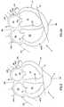
- FIGS. 1 and 1Aa normal, healthy human heart H′ is schematically shown in cross-section and will now be described in order to facilitate an understanding of the present invention.
- the heart H′is shown during systole (i.e., high left ventricular pressure).
- the heart H′is shown during diastole (i.e., low left ventricular pressure).
- the heart H′is a muscle having an outer wall or myocardium MYO′ and an internal wall or septum SP′.
- the myocardium MYO′ and septum SP′define four internal heart chambers including a right atrium RA′, a left atrium LA′, a right ventricle RV′ and a left ventricle LV′.
- the heart H′has a length measured along a longitudinal axis BB′-AA′ from an upper end or base B′ to a lower end or apex A′.
- the right and left atria RA′, LA′reside in an upper portion UP′ of the heart H′ adjacent the base B′.
- the right and left ventricles RV′, LV′reside in a lower portion LP′ of the heart H′ adjacent the apex A′.
- the ventricles RV′, LV′terminate at ventricular lower extremities LE′ adjacent the apex A′ and spaced there from by the thickness of the myocardium MYO′.
- A-V (atrio-ventricular) groove AVG′Extending away from the upper portion UP′ are a plurality of major blood vessels communicating with the chambers RA′, RV′, LA′, LV′. For ease of illustration, only the superior vena cava SVC′, inferior vena cava IVC′ and a left pulmonary vein LPV′ are shown as being representative.
- the heart H′contains valves to regulate blood flow between the chambers RA′, RV′, LA′, LV′ and between the chambers and the major vessels (e.g., the superior vena cava SVC′, inferior vena cava IVC′ and a left pulmonary vein LPV′).
- the major vesselse.g., the superior vena cava SVC′, inferior vena cava IVC′ and a left pulmonary vein LPV′.
- the major vesselse.g., the superior vena cava SVC′, inferior vena cava IVC′ and a left pulmonary vein LPV′.
- the major vesselse.g., the superior vena cava SVC′, inferior vena cava IVC′ and a left pulmonary vein LPV′.
- the tricuspid valve TV′ between the right atrium RA′ and right ventricle RV′ and the mitral valve MV′ between the left atrium LA′ and left ventricle LV′are shown
- the valvesare secured, in part, to the myocardium MYO′ in a region of the lower portion LP′ adjacent the A-V groove AVG′ and referred to as the valvular annulus VA′.
- the valves TV′ and MV′open and close through the beating cycle of the heart H.
- FIGS. 1 and 1Ashow a normal, healthy heart H′ during systole and diastole, respectively.
- the myocardium MYO′is contracting and the heart assumes a shape including a generally conical lower portion LP′.
- the heart H′is expanding and the conical shape of the lower portion LP′ bulges radially outwardly (relative to axis AA′-BB′).
- the motion of the heart H′ and the variation in the shape of the heart H′ during contraction and expansionis complex.
- the amount of motionvaries considerably throughout the heart H′.
- the motionincludes a component which is parallel to the axis AA′-BB′ (conveniently referred to as longitudinal expansion or contraction).
- the motionalso includes a component perpendicular to the axis AA′-BB′ (conveniently referred to as circumferential expansion or contraction).
- FIG. 1Having described a healthy heart H′ during systole (FIG. 1) and diastole (FIG. 1 A), comparison can now be made with a heart deformed by congestive heart disease.
- a heart His shown in systole in FIG. 2 and in diastole in FIG. 2 A. All elements of diseased heart H are labeled identically with similar elements of healthy heart H′ except only for the omission of the apostrophe in order to distinguish diseased heart H from healthy heart H′.
- FIGS. 1 and 2showing hearts H′ and H during systole
- the lower portion LP of the diseased heart Hhas lost the tapered conical shape of the lower portion LP′ of the healthy heart H′. Instead, the lower portion LP of the diseased heart H dilates outwardly between the apex A and the A-V groove AVG. So deformed, the diseased heart H during systole (FIG. 2) resembles the healthy heart H′ during diastole (FIG. 1 A). During diastole (FIG. 2 A), the deformation is even more extreme.
- the heart HAs a diseased heart H enlarges from the representation of FIGS. 1 and 1A to that of FIGS. 2 and 2A, the heart H becomes a progressively more inefficient pump. Therefore, the heart H requires more energy to pump the same amount of blood. Continued progression of the disease results in the heart H being unable to supply adequate blood to the patient's body and the patient becomes symptomatic of cardiac insufficiency.
- the enlargement of the heart Hcan lead to valvular disorders.
- the leaflets of the valves TV and MVmay spread apart. After a certain amount of enlargement, the spreading may be so severe that the leaflets cannot completely close. Incomplete closure results in valvular regurgitation contributing to an additional degradation in cardiac performance.
- circumferential enlargement of the valvular annulus VAmay contribute to valvular dysfunction as described, the separation of the valve leaflets is most commonly attributed to deformation of the geometry of the heart H.
- a treatment method and apparatusare described in commonly assigned U.S. Pat. No. 6,085,754.
- a jacketis configured to surround the myocardium MYO. While the method of the present invention will be described with reference to a jacket as described in commonly assigned U.S. Pat. No. 6,085,754, it will be appreciated that the present invention is applicable to other cardiac constraint devices including those shown in U.S. Pat. No. 5,800,528 and PCT International Publication No. WO 98/29401.
- the cardiac constraint deviceis shown as a jacket 10 , 10 ′ of flexible, biologically compatible material.
- the jacket 10 , 10 ′is an enclosed knit material having upper and lower ends 12 , 12 ′, 14 , 14 ′.
- the jacket 10 , 10 ′defines an internal volume 16 , 16 ′ which is completely enclosed but for the open ends 12 , 12 ′ and 14 ′.
- lower end 14is closed.
- lower end 14 ′is open.
- upper ends 12 , 12 ′are open.
- FIG. 3will be discussed. Elements in common between the embodiments of FIGS. 3 and 4 are numbered identically with the addition of an apostrophe to distinguish the second embodiment and such elements need not be separately discussed.
- the jacket 10is dimensioned with respect to a heart H to be treated. Specifically, the jacket 10 is sized for the heart H to be constrained within the volume 16 . The jacket 10 can be slipped around the heart H. The jacket 10 has a length L between the upper and lower ends 12 , 14 sufficient for the jacket 10 to constrain the lower portion LP. The upper end 12 of the jacket 10 extends at least to A-V groove AVG and further extends to the lower portion LP to constrain at least the lower ventricular extremities LE.
- the lower portion LPWhen the parietal pericardium is opened, the lower portion LP is free of obstructions for applying the jacket 10 over the apex A. If, however, the parietal pericardium is intact, the diaphragmatic attachment to the parietal pericardium inhibits application of the jacket over the apex A of the heart. In this situation, the jacket can be opened along a line extending from the upper end 12 ′ to the lower end 14 ′ of jacket 10 ′. The jacket can then be applied around the pericardial surface of the heart and the opposing edges of the opened line secured together after placed on the heart. Systems for securing the opposing edges are disclosed in, for example, U.S. Pat. No. 5,702,343, the entire disclosure of which is incorporated herein by reference. The lower end 14 ′ can then be secured to the diaphragm or associated tissues using, for example, sutures, staples, etc.
- the lower end 14is closed and the length L is sized for the apex A of the heart H to be received within the lower end 14 when the upper end 12 is placed at the A-V groove AVG.
- the lower end 14 ′is open and the length L′ is sized for the apex A of the heart H to protrude beyond the lower end 14 ′ when the upper end 12 ′ is placed at the A-V groove AVG.
- the length L′is sized so that the lower end 14 ′ extends beyond the lower ventricular extremities LE such that in both of jackets 10 , 10 ′, the myocardium MYO surrounding the ventricles RV, LV is in direct opposition to material of the jacket 10 , 10 ′ during diastole.
- Such placementis desirable for the jacket 10 , 10 ′ to present a constraint against dilation of the ventricular portion of the heart H.
- the jacket 10is secured to the heart.
- the jacket 10is secured to the heart H using sutures (or other fastening means such as staples).
- the jacket 10is sutured to the heart H at suture locations S circumferentially spaced along the upper end 12 . While a surgeon may elect to add additional suture locations to prevent shifting of the jacket 10 after placement, the number of such locations S is preferably limited so that the jacket 10 does not restrict contraction of the heart H during systole,
- the fibers 20 of the knit fabric 18are preferably non-expandable. While all materials expand to at least a small amount, the individual fibers 20 do not substantially stretch in response to force. In response to the low pressures in the heart H during diastole, the fibers 20 are generally inelastic. In a preferred embodiment, the fibers are 70 Denier polyester. While polyester is presently preferred, other suitable materials include polytetrafluoroethylene (PTFE), expanded PTFE (ePTFE) and polypropylene.
- PTFEpolytetrafluoroethylene
- ePTFEexpanded PTFE
- polypropylenepolypropylene
- the knit materialhas numerous advantages. Such a material is flexible to permit unrestricted movement of the heart H (other than the desired constraint on circumferential expansion).
- the materialis open defining a plurality of interstitial spaces for fluid permeability as well as minimizing the amount of surface area of direct contact between the heart H and the material of the jacket 10 (thereby minimizing areas of irritation or abrasion) to minimize fibrosis and scar tissue.
- the open areas of the knit constructionalso allow for electrical connection between the heart and surrounding tissue for passage of electrical current to and from the heart.
- the knit materialis an electrical insulator
- the open knit constructionis sufficiently electrically permeable to permit the use of trans-chest defibrillation of the heart.
- the open, flexible constructionpermits passage of electrical elements (e.g., pacer leads) through the jacket.
- the open constructionpermits visibility of the epicardial surface, thereby minimizing limitations to performing other procedures, e.g., coronary bypass, to be performed without removal of the jacket.
- the fabric 18is preferably tear and run resistant. In the event of a material defect or inadvertent tear, such a defect or tear is restricted from propagation by reason of the knit construction.
- the jacket 10constrains further undesirable circumferential enlargement of the heart while not impeding other motion of the heart H.
- the jacket 10need not be directly applied to the epicardium (i.e., outer surface of the myocardium) but could be placed over the parietal pericardium.
- an anti-fibrosis liningsuch as a PTFE coating on the fibers of the knit
- the fibers 20can be coated with PTFE.
- the jacket 10can be used in the early stages of congestive heart disease. For patients facing heart enlargement due to viral infection, the jacket 10 permits constraint of the heart H for a sufficient time to permit the viral infection to pass. In addition to preventing further heart enlargement, the jacket 10 treats valvular disorders by constraining circumferential enlargement of the valvular annulus and deformation of the ventricular walls.
- the volume and shape of the jacket 10are larger than the lower portion LP during diastole. So sized, the jacket 10 may be easily slipped around the heart H. Once placed, the jacket's volume and shape are adjusted for the jacket 10 to snugly conform to the external geometry of the heart H during diastole. Such sizing is easily accomplished due to the knit construction of the jacket 10 . For example, excess material of the jacket 10 can be gathered and sutured S′′ (FIG. 5) to reduce the volume 16 of the jacket 10 and conform the jacket 10 to the shape of the heart H during diastole. Such shape represents a maximum adjusted volume.
- the jacket 10constrains enlargement of the heart H beyond the maximum adjusted volume without restricting contraction of the heart H during systole.
- the jacket 10can be provided with other arrangements for adjusting volume.
- the jacketcan be provided with a slot. The edges of the slot can be drawn together to reduce the volume of the jacket.
- the jacket 10is adjusted to a snug fit on the heart H during diastole. Care is taken to avoid tightening the jacket 10 too much such that cardiac function is impaired.
- the left ventricle LVfills with blood. If the jacket 10 is too tight, the left ventricle LV cannot adequately expand and left ventricular pressure will rise.
- the surgeoncan monitor left ventricular pressure.
- pulmonary wedge pressureuses a catheter placed in the pulmonary artery. The wedge pressure provides an indication of filling pressure in the left atrium LA and left ventricle LV. While minor increases in pressure (e.g., 2-3 mm Hg) can be tolerated, the jacket 10 is snugly fit on the heart H but not so tight as to cause a significant increase in left ventricular pressure during diastole.
- Jacket selectionmay be facilitated by a method for obtaining an accurate measurement of the heart's size prior to selecting a jacket 10 .
- Co-pending U.S. application Ser. No. 09/399,703(the “'703” application), now U.S. Pat. No. 6,179,791, discloses a device capable of measuring a heart.
- the configuration of the device of the '703 applicationrequires invasive surgery to obtain the measurements.
- the present inventioncan obtain similar measurements using less invasive surgical techniques.
- the device 30for obtaining a measurement of a heart H is depicted.
- the device 30includes a handle 31 having a distal end 32 and a proximal end 33 .
- the device 30also includes a measuring portion 24 .
- the proximal end 33includes a hinged region 37 .
- the handle 31includes two handle members, a first handle member 35 , and a second handle member 36 .
- the first handle member 35has a distal end 44 and a proximal end 46 .
- the second handle member 36has a distal end 45 and a proximal end 47 .
- the first and second handle members, 35 and 36can be made of any material that is able to be sterilized.
- sterilizationcan be accomplished by any acceptable method, examples of which are: autoclaving (steam sterilization), dry-heat sterilization, gas sterilization (with ethylene oxide for example), radiation sterilization, filtration, sterilization by liquid sterilants, hydrogen peroxide vapor, hydrogen peroxide plasma, peroxy acetic acid, and UV radiation.
- the first and second handle members, 35 and 36can be made of a material typically used in the manufacturing of medical devices. Examples of suitable materials include plastics, such as polyethylene, annealed stainless steel, brass or aluminum.
- the device 30also includes a flexible member 40 .
- the flexible member 40contains at least one marked region.
- the flexible member 40includes a first non-marked region 41 and a second marked region 42 .
- the second marked region 42contains markings 43 evenly spaced apart by any convenient measurement unit (e.g. inches and fractions thereof, centimeters, millimeters, etc. . . . ).
- the flexible member 40 and first and second handle members 35 and 36can be constructed using a disposable material that is cost effective to discard after every use.
- the flexible member 40is further characterized.
- the flexible member 40includes a proximal region 61 , a transition region 60 and a distal region 62 .
- the proximal region 61is located within the first non-marked region 41 of the flexible member 40 .
- the transition region 60is also located within the first non-marked region 41 of the flexible member 40 .
- the distal region 62forms the remainder of the first non-marked region 41 and the second marked region 42 of the flexible member 40 .
- the distal region 62includes a distal end 63 .
- the proximal region 61has a diameter or width greater than the diameter or width of the distal region 62 .
- the difference in the diameter of the proximal region 61 and the distal region 62is defined by the first handle member 35 as will be discussed below.
- the proximal regionwill have a diameter that is at least 20% larger than the distal region 62 .
- the transition region 60has a diameter that either gradually decreases from one end to the other, or decreases in a non-gradual manner. The decrease in diameter is defined by the difference in the diameter of the proximal region 61 and the distal region 62 .
- the flexible member 40can be made of any material that can be sterilized, and is somewhat flexible.
- the flexible member 40can be made of any material that can be sterilized, and is somewhat flexible, for example: a polymer with a durometer of 50 to 90 Shore A.
- the flexible member 40is made of a material typically used in the production of medical devices. Examples of material that could be used to make the flexible member 40 include plastics, such as polyethylene or PVC.
- the handle 31comprises a first handle member 35 and a second handle member 36 .
- the handle 31may be configured so that the first and second handle members 35 and 36 are connected; for example through a hinge. If a hinge is utilized, it can be configured so that the first handle member 35 defines a connection receiving element 70 .
- the second handle member 36defines a connection element 38 .
- the connection receiving element 70 and the connection element 38can be configured in any way that allows connection between the first and second handle members 35 and 36 .
- connection element 38can be configured as an extension off of the second handle member 36 and the connection receiving element 70 can be an extension off the first handle member 35 that is configured for the connection element 38 to fit in.
- the handle 31is assembled by connecting the first handle member 35 to the second handle member 36 by engaging the connection receiving element 70 of the first handle member 35 to the connection element 38 of the second handle member 36 .
- the connection of the first and second handle members 35 and 36defines a hinged region 37 at the proximal end 33 of the handle 31 .
- connection receiving element 70 of the first handle member 35 and the connection element 38 of the second handle member 36are manufactured using the same material as the first and second handle members, 35 and 36 .
- connection receiving element 70 and the connection element 38are molded as part of the first and second handle members 35 and 36 .
- the first and second handle members 35 and 36each define a lumen 71 and 72 respectively.
- the lumens 71 and 72 within the first and second handle members 35 and 36respectively, run lengthwise, from the proximal to distal ends (or vice versa) of the first and second handle members 35 and 36 .
- first handle member 35one embodiment of a first handle member 35 is described.
- the distal end 44 of the first handle member 35defines a first aperture 51 .
- the first aperture 51has a diameter 50 that is greater than the diameter of the distal region 62 of the flexible member 40 , such that the distal region 62 of the flexible member 40 is able to freely move along the length of the lumen 71 .
- the proximal end 46 of first handle member 35defines a second aperture 53 .
- the second aperture 53has a diameter 52 that is greater than the diameter of the distal region 62 , the transition region 60 and the proximal region 61 of flexible member 40 , such that the distal region 62 of the flexible member 40 is able to freely move along the length of the lumen 71 .
- the lumen 71 of the first handle member 35is defined by the first and second apertures 51 and 53 , as discussed above.
- the lumen 71 of the first handle member 35is further defined by the way in which the transition region 60 fits in it.
- the lumen 71is configured so that the flexible member 40 cannot freely move through the entire length of the lumen 71 of the first handle member 35 .
- the configuration of the lumen 71is more fully described below in the section describing assembly of the device 30 .
- the distal end 45 of a second handle member 36defines a third aperture 55 .
- the third aperture 55has a diameter 54 greater than the diameter of the distal region 62 of the flexible member 40 , such that the distal region 62 of the flexible member 40 can freely move through the lumen 72 .
- the proximal end 47 of the second handle member 36defines a fourth aperture 57 .
- the fourth aperture 57has a diameter 56 that is greater than the diameter of the distal region 62 of the flexible member 40 , such that the distal region 62 can freely move through the lumen 72 .
- the lumen 72 of the second handle member 36has a constant diameter along the length of the second handle member 36 .
- the device 30is assembled by inserting the flexible member 40 inside the lumens 71 , 72 of the handle members 35 , 36 .
- the procedurewill now be explained with reference to FIGS. 6 through 9.
- the distal end 63 of the distal region 62 of the flexible member 40is inserted into the second aperture 53 of the first handle member 35 .
- the flexible member 40is then threaded through the lumen 71 of the first handle member 35 .
- the distal end 63 of the distal region 62 of the flexible member 40is threaded out of the lumen 71 of the first handle member 35 through the first aperture 51 .
- the flexible member 40is then threaded through the lumen 71 of the first handle member 35 .
- the diameter of the lumen 71 of the first handle member 35is configured such that the diameter of the lumen 71 at the proximal end 46 of the handle is greater than the diameter of the lumen 71 at the distal end 74 of the first handle member 35 , such that the transition region 60 of the flexible member 40 cannot freely move along the entire length of the lumen 71 defined by the first handle member 35 .
- the flexible member 40is anchored in the lumen 71 of the first handle member 35 when the transition region 60 abuts the transition area 73 of the lumen 71 .
- the distal end 63 of the distal region portion 62 of the flexible member 40is threaded into the third aperture 55 of the second handle member 36 and threaded through the lumen 72 of the second handle member 36 .
- the distal end 63 of the distal region 62 of the flexible member 40is then threaded out of the fourth aperture 57 of the second handle member 36 .
- the device 30has three parts, a handle 31 , an adjustable loop 34 , (made up of the flexible member 40 ) and a measurement region 49 .
- the assembled device 30can be used to measure different aspects of the heart.
- One measurement that can be accomplished with the device 30 of the present inventionis the size of the heart.
- the size of the heartcan be measured using the device 30 , as depicted in FIG. 12 .
- the adjustable loop 34is enlarged by increasing the length of the flexible member 40 extending between the handle members.
- the adjustable loop 34is enlarged by urging the distal end 63 of the flexible member 40 towards the fourth aperture 57 of the second handle member 36 , so that the flexible member 40 moves out of the third aperture 55 of the second handle member 36 .
- the adjustable loop 34can then be placed around the region of the heart H to be measured.
- the distal regions 44 and 45 of the handle members 35 and 36are brought towards each other to minimize the void 39 .
- the distal end 63 of the flexible member 40is pulled away from the fourth aperture 57 of the second handle member 36 such that excess flexible member 40 in the adjustable loop 34 is retracted back through the lumen 72 of the second handle member 36 until loop 34 fits snugly around the heart H.
- One method of determining the value of this measurement of the heartis to note the specific marking 43 that is present at the intersection defined by the flexible member 40 and the fourth aperture 57 of second handle member 36 .
- the second handle member 36could be equipped with a viewing window at its proximal end 47 .
- the measurementwould be given a value by noting the marking viewed through this window.
- the second handle member 36could be configured to determine the value at the distal end 45 .
- measurementis determined by comparing a first position on the flexible member 40 with a second position located somewhere on the second handle member 36 .
- the first position on the flexible member 40could be where it extends out of the proximal end 47 of the second handle member 36
- the second positioncould be on the second handle member 36 where the flexible member 40 extends out of the second handle member 36 .
- the device 30is being used to measure another aspect of the heart H, a surface length of the heart H.
- One such surface length of the heart His from the A-V groove AVG to the apex A. If the device 30 being utilized has a hinge, the connection receiving element 70 of the first handle member 35 is disengaged from the connection element 38 of the second handle member 36 . Then, the distal end 44 of first handle member 35 is placed against the heart H at the A-V groove AVG.
- the flexible member 40is then placed along the heart H and the distal end 63 of the flexible member 40 is pulled away from the fourth aperture 57 of the second handle member 36 so that the portion of the flexible member 40 that made up the loop region 34 is decreased until the distal end 45 of the second handle member 36 is on the apex A of the heart H.
- the surface length of the heartcan then be measured by comparing the first position on the flexible member 40 with the second position on the first handle member 35 .
- FIG. 14depicts the device 30 measuring another measurement of the heart H; the apex A of the heart H.
- the device 30is used in a manner analogous to that described above for measuring the surface length of the heart H from the A-V groove AVG to the apex A. It will be appreciated that any measurements of physical aspects of the heart can be undertaken with the device 30 of the invention.
- FIG. 15illustrates another embodiment of the invention.
- the second handle member 36is equipped with markings 70 evenly spaced apart by any convenient measurement unit (e.g. centimeters, inches or fractions thereof, millimeters, etc. . . . ) so that the second handle member 36 can also be used as a ruler.
- the first handle member 35can be marked similarly.
- the first or second handle members 35 or 36 so markedcan be used for other measurements of the heart H, such as to determine apex A to base B.
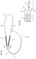
- FIGS. 16, 17 , and 17 aAnother embodiment of the device of the invention is illustrated in FIGS. 16, 17 , and 17 a .
- the device 99includes a first and second handle member 110 and 111 and a flexible member 101 .
- FIG. 17Aillustrates both a first and second handle member 110 and 111 and their corresponding elements.
- the first and second handle members 110 and 111each define a lumen 120 and 121 along the length of the handle member 110 , 111 , respectively.
- the proximal end 106 and distal end 107 of the first handle member 110define first and second apertures 122 and 123 .
- the proximal end 108 and distal end 109 of the second handle member 111define third and fourth apertures 124 and 125 .
- the diameter of the lumen 120 and 121are constant along the length of the first and second handle members 110 and 111 .
- the first handle member 110does not have a lumen 120 configured to anchor the flexible member 101 .
- the flexible member 101is configured to be anchored within the lumen 120 of the first handle member 110 .
- the handle members 110 and 111can be identical and interchangeable.
- the first and second handle members 110 and 111can be made of any material that is sterilizable.
- the first and second handle members 110 and 111are made of materials typically used in the manufacturing of medical devices. Examples of materials that could be used to make the first and second handle members 110 and 111 include plastics, such as polyethlyne, annealed stainless steel, brass or aluminum. If desired, the flexible member 101 and the first and second handle members 110 and 111 can be manufactured using a disposable material that is cost effective to discard after every use.
- the flexible member 101 of device 99again has a first non-marked region 103 and a second marked region 102 that includes markings 70 evenly spaced apart by any convenient measurement unit (e.g., inches, fractions thereof, centimeters or millimeters, etc. . . . ).
- the flexible member 101includes an enlarged portion 104 on the proximal end 130 of the first non-marked region 103 , and a distal end 131 of the second marked region 102 .
- the enlarged portion 104has a diameter that is greater than the diameter of all of the apertures 122 , 123 , 124 and 125 of the first and second handle members 110 and 111 .
- the distal end 131has the same diameter as the remainder of the flexible member 101 (excluding the enlarged portion 104 ).
- the flexible member 101can be made of any material that can be sterilized, and is somewhat flexible, for example: a polymer with a durometer of 50 to 90 Shore A.
- the flexible member 101is made of a material typically used in the production of medical devices. Examples of material that could be used to make the flexible member 101 include plastics, such as polyethylene or PVC.
- FIG. 18depicts the assembled device 99 .
- the distal end 131 of the flexible member 101is threaded through the proximal end 106 of the first handle member 110 .
- the flexible member 101is then urged through the first lumen 120 of the first handle member 110 so it exits at the distal end 107 of the first handle member 110 .
- the flexible member 101is then urged through the lumen 120 of the first handle member 110 until the enlarged portion 104 abuts the proximal end 106 of the first handle member 110 .
- the flexible member 101is then threaded into the distal end 109 of the second handle member 111 , extended through the lumen 121 of the second handle member 111 , and extended out the proximal end 108 of the second handle member 111 .
- the device 99has three parts: a two component handle 100 , an adjustable loop 112 , (made up of the flexible member 101 ) and a measurement region 113 .
- This adjustable loop 112 along with the measurement region 113are used to measure the heart.
- FIG. 19illustrates a close up view of the proximal end 132 of the device 99 showing one example of how a specific measurement can be read using the device 99 .
- the specific value for the measurementcan also be determined in other ways and still be within the scope of the present invention.
- the first handle member 110could be equipped with a viewing window at its proximal end 106 . The measurement would be given a value by noting the marking viewed through this window.
- the first handle member 110could be configured to determine the value at the distal end 107 .
- measurementis determined by comparing a first position on the flexible member 101 with a second position located somewhere on the first handle member 110 .
- the first position on the flexible member 101could be where it extends out of the proximal end 106 of the first handle member 110
- the second positioncould be on the first handle member 110 where the flexible member 101 extends out of the first handle member 110 .
Landscapes
- Health & Medical Sciences (AREA)
- Cardiology (AREA)
- Life Sciences & Earth Sciences (AREA)
- Animal Behavior & Ethology (AREA)
- Oral & Maxillofacial Surgery (AREA)
- Veterinary Medicine (AREA)
- Public Health (AREA)
- Engineering & Computer Science (AREA)
- Biomedical Technology (AREA)
- Heart & Thoracic Surgery (AREA)
- General Health & Medical Sciences (AREA)
- Biophysics (AREA)
- Surgery (AREA)
- Molecular Biology (AREA)
- Medical Informatics (AREA)
- Pathology (AREA)
- Physics & Mathematics (AREA)
- Dentistry (AREA)
- Transplantation (AREA)
- Vascular Medicine (AREA)
- Surgical Instruments (AREA)
- Prostheses (AREA)
- Media Introduction/Drainage Providing Device (AREA)
Abstract
Description
Claims (14)
Priority Applications (2)
| Application Number | Priority Date | Filing Date | Title |
|---|---|---|---|
| US09/780,202US6575921B2 (en) | 2001-02-09 | 2001-02-09 | Device for heart measurement |
| PCT/US2002/002649WO2002064035A1 (en) | 2001-02-09 | 2002-01-30 | Device for heart measurement |
Applications Claiming Priority (1)
| Application Number | Priority Date | Filing Date | Title |
|---|---|---|---|
| US09/780,202US6575921B2 (en) | 2001-02-09 | 2001-02-09 | Device for heart measurement |
Publications (2)
| Publication Number | Publication Date |
|---|---|
| US20020111567A1 US20020111567A1 (en) | 2002-08-15 |
| US6575921B2true US6575921B2 (en) | 2003-06-10 |
Family
ID=25118930
Family Applications (1)
| Application Number | Title | Priority Date | Filing Date |
|---|---|---|---|
| US09/780,202Expired - LifetimeUS6575921B2 (en) | 2001-02-09 | 2001-02-09 | Device for heart measurement |
Country Status (2)
| Country | Link |
|---|---|
| US (1) | US6575921B2 (en) |
| WO (1) | WO2002064035A1 (en) |
Cited By (33)
| Publication number | Priority date | Publication date | Assignee | Title |
|---|---|---|---|---|
| US20020019580A1 (en)* | 2000-03-10 | 2002-02-14 | Lilip Lau | Expandable cardiac harness for treating congestive heart failure |
| US6678962B1 (en)* | 1999-11-17 | 2004-01-20 | Cardiomend Llc | Device and method for assessing the geometry of a heart valve |
| US20040267329A1 (en)* | 2001-09-07 | 2004-12-30 | Mardil, Inc. | Method and apparatus for external heart stabilization |
| US20050102011A1 (en)* | 2003-11-07 | 2005-05-12 | Lilip Lau | Cardiac harness for treating congestive heart failure and for defibrillating and/or pacing/sensing |
| US20060270896A1 (en)* | 2005-05-31 | 2006-11-30 | Ethicon, Inc. | Method and device for deployment of a sub-pericardial sack |
| US7158839B2 (en) | 2003-11-07 | 2007-01-02 | Paracor Medical, Inc. | Cardiac harness for treating heart disease |
| US20070032409A1 (en)* | 2005-01-26 | 2007-02-08 | Vanderbilt University | Bradykinin receptor antagonists and uses thereof |
| US7174896B1 (en) | 2002-01-07 | 2007-02-13 | Paracor Medical, Inc. | Method and apparatus for supporting a heart |
| US7189203B2 (en) | 2002-11-15 | 2007-03-13 | Paracor Medical, Inc. | Cardiac harness delivery device and method |
| US7229405B2 (en) | 2002-11-15 | 2007-06-12 | Paracor Medical, Inc. | Cardiac harness delivery device and method of use |
| US7276021B2 (en) | 2001-10-31 | 2007-10-02 | Paracor Medical, Inc. | Heart failure treatment device and method |
| US7282024B2 (en) | 2004-01-12 | 2007-10-16 | Paracor Medical, Inc. | Cardiac harness having interconnected strands |
| US7291105B2 (en) | 2003-07-10 | 2007-11-06 | Paracor Medical, Inc. | Self-anchoring cardiac harness |
| US7381181B2 (en) | 2001-09-10 | 2008-06-03 | Paracor Medical, Inc. | Device for treating heart failure |
| US7485089B2 (en) | 2002-09-05 | 2009-02-03 | Paracor Medical, Inc. | Cardiac harness |
| US20090062596A1 (en)* | 2007-09-05 | 2009-03-05 | Leinsing Karl R | Heart band with fillable chambers to modify heart valve function |
| US7587247B2 (en) | 2005-08-01 | 2009-09-08 | Paracor Medical, Inc. | Cardiac harness having an optimal impedance range |
| US7736299B2 (en) | 2002-11-15 | 2010-06-15 | Paracor Medical, Inc. | Introducer for a cardiac harness delivery |
| US20100160832A1 (en)* | 2008-12-19 | 2010-06-24 | St. Jude Medical, Inc. | Apparatus and method for measuring blood vessels |
| WO2010111592A1 (en) | 2009-03-27 | 2010-09-30 | Acorn Cardiovascular, Inc. | Intra-operative heart size measuring tool |
| US20110071622A1 (en)* | 2009-09-23 | 2011-03-24 | Fehling Instruments Gmbh & Co. Kg | Instrument for the surgical treatment of aortic valve defects |
| US7976454B2 (en) | 2002-01-07 | 2011-07-12 | Paracor Medical, Inc. | Cardiac harness |
| US8192351B2 (en) | 2007-08-13 | 2012-06-05 | Paracor Medical, Inc. | Medical device delivery system having integrated introducer |
| US20120191015A1 (en)* | 2004-10-29 | 2012-07-26 | Depuy Products, Inc. | Coordinate instrument set |
| USD717954S1 (en) | 2013-10-14 | 2014-11-18 | Mardil, Inc. | Heart treatment device |
| US9370425B2 (en) | 2012-10-12 | 2016-06-21 | Mardil, Inc. | Cardiac treatment system and method |
| US20160256075A1 (en)* | 2015-03-03 | 2016-09-08 | Transseptal Solutions Ltd. | Measurement of appendage openings |
| US9706982B2 (en) | 2015-03-03 | 2017-07-18 | Transseptal Solutions Ltd. | Treatment of appendage openings |
| US9737403B2 (en) | 2006-03-03 | 2017-08-22 | Mardil, Inc. | Self-adjusting attachment structure for a cardiac support device |
| US9788858B2 (en) | 2013-04-15 | 2017-10-17 | Transseptal Solutions Ltd. | Fossa ovalis penetration using probing elements |
| US10398503B2 (en) | 2015-10-14 | 2019-09-03 | Transseptal Soulutions Ltd. | Fossa ovalis penetration |
| US10500371B2 (en) | 2014-10-14 | 2019-12-10 | Transseptal Solutions Ltd. | Fossa ovalis penetration |
| US12426922B2 (en) | 2013-04-15 | 2025-09-30 | Transseptal Solutions Ltd. | Fossa ovalis penetration catheter |
Families Citing this family (22)
| Publication number | Priority date | Publication date | Assignee | Title |
|---|---|---|---|---|
| US6161543A (en) | 1993-02-22 | 2000-12-19 | Epicor, Inc. | Methods of epicardial ablation for creating a lesion around the pulmonary veins |
| US6311692B1 (en) | 1996-10-22 | 2001-11-06 | Epicor, Inc. | Apparatus and method for diagnosis and therapy of electrophysiological disease |
| US7052493B2 (en) | 1996-10-22 | 2006-05-30 | Epicor Medical, Inc. | Methods and devices for ablation |
| US6719755B2 (en) | 1996-10-22 | 2004-04-13 | Epicor Medical, Inc. | Methods and devices for ablation |
| US20040260278A1 (en)* | 1996-10-22 | 2004-12-23 | Anderson Scott C. | Apparatus and method for ablating tissue |
| US7883539B2 (en) | 1997-01-02 | 2011-02-08 | Edwards Lifesciences Llc | Heart wall tension reduction apparatus and method |
| US6050936A (en) | 1997-01-02 | 2000-04-18 | Myocor, Inc. | Heart wall tension reduction apparatus |
| US8709007B2 (en)* | 1997-10-15 | 2014-04-29 | St. Jude Medical, Atrial Fibrillation Division, Inc. | Devices and methods for ablating cardiac tissue |
| US6332893B1 (en) | 1997-12-17 | 2001-12-25 | Myocor, Inc. | Valve to myocardium tension members device and method |
| US6260552B1 (en) | 1998-07-29 | 2001-07-17 | Myocor, Inc. | Transventricular implant tools and devices |
| US8308719B2 (en) | 1998-09-21 | 2012-11-13 | St. Jude Medical, Atrial Fibrillation Division, Inc. | Apparatus and method for ablating tissue |
| EP1207788A4 (en)* | 1999-07-19 | 2009-12-09 | St Jude Medical Atrial Fibrill | Apparatus and method for ablating tissue |
| US6723038B1 (en) | 2000-10-06 | 2004-04-20 | Myocor, Inc. | Methods and devices for improving mitral valve function |
| US6764510B2 (en) | 2002-01-09 | 2004-07-20 | Myocor, Inc. | Devices and methods for heart valve treatment |
| US20070293855A1 (en)* | 2002-02-15 | 2007-12-20 | Sliwa John W Jr | Methods and devices for ablation |
| US7112219B2 (en) | 2002-11-12 | 2006-09-26 | Myocor, Inc. | Devices and methods for heart valve treatment |
| US7247134B2 (en) | 2002-11-12 | 2007-07-24 | Myocor, Inc. | Devices and methods for heart valve treatment |
| US9314298B2 (en) | 2007-04-17 | 2016-04-19 | St. Jude Medical, Atrial Fibrillation Divisions, Inc. | Vacuum-stabilized ablation system |
| US10828064B2 (en)* | 2018-03-01 | 2020-11-10 | Torax Medical, Inc. | Laparoscopic sizing instrument |
| CN119454164A (en) | 2018-04-30 | 2025-02-18 | 波士顿科学有限公司 | System and method for object size estimation |
| US11963685B2 (en)* | 2019-07-09 | 2024-04-23 | Cilag Gmbh International | Esophagus sizing instrument |
| WO2023107332A1 (en)* | 2021-12-06 | 2023-06-15 | Edwards Lifesciences Corporation | Sizer for left atrial appendage |
Citations (54)
| Publication number | Priority date | Publication date | Assignee | Title |
|---|---|---|---|---|
| US2241451A (en)* | 1940-06-19 | 1941-05-13 | Harry S Fist | Surgical measuring instrument |
| US3983863A (en) | 1975-06-02 | 1976-10-05 | American Hospital Supply Corporation | Heart support for coronary artery surgery |
| US4043043A (en)* | 1975-11-03 | 1977-08-23 | Aylmer Raymond Pace | Device for measuring the amount of product in bottles, jars and containers |
| US4048990A (en) | 1976-09-17 | 1977-09-20 | Goetz Robert H | Heart massage apparatus |
| SU986392A1 (en) | 1981-03-13 | 1983-01-07 | Украинский Научно-Исследовательский Институт Протезирования,Протезостроения,Экспертизы И Восстановления Трудоспособности Инвалидов | Extremity perimeter measuring device |
| SU1009457A1 (en) | 1981-07-15 | 1983-04-07 | Проблемная Лаборатория "Вспомогательного Кровообращения" Благовещенского Медицинского Института | Artificial pericardium |
| US4403604A (en) | 1982-05-13 | 1983-09-13 | Wilkinson Lawrence H | Gastric pouch |
| US4428385A (en)* | 1981-10-30 | 1984-01-31 | Queen's University Of Kingston | Device for measuring male potency |
| US4428375A (en) | 1982-02-16 | 1984-01-31 | Ellman Barry R | Surgical bag for splenorrhaphy |
| DE3336121A1 (en) | 1983-10-05 | 1985-04-18 | Olympus Winter & Ibe GmbH, 2000 Hamburg | Device for Charrière determination |
| JPS60203250A (en) | 1984-03-29 | 1985-10-14 | 日本ゼオン株式会社 | heart surgery patch |
| SU1232214A1 (en) | 1981-12-24 | 1986-05-23 | Казанский научно-исследовательский институт травматологии и ортопедии | Apparatus for measuring circumference of manъs body segments |
| US4630597A (en) | 1984-04-30 | 1986-12-23 | Adrian Kantrowitz | Dynamic aortic patch for thoracic or abdominal implantation |
| US4690134A (en) | 1985-07-01 | 1987-09-01 | Snyders Robert V | Ventricular assist device |
| EP0280564A2 (en) | 1987-02-27 | 1988-08-31 | Intermedics, Inc. | Implantable defribrillation electrodes |
| DE3831540A1 (en) | 1987-09-16 | 1989-04-06 | Phillip H Evans | VENTILATION DEVICE FOR CARDIOVASCULAR PUMPS |
| US4821723A (en) | 1987-02-27 | 1989-04-18 | Intermedics Inc. | Biphasic waveforms for defibrillation |
| US4878890A (en) | 1986-10-15 | 1989-11-07 | Ethicon, Inc. | Perihepatic prosthesis |
| US4914821A (en)* | 1989-02-03 | 1990-04-10 | Burlington Optical, Inc. | Sizer |
| US4920659A (en) | 1988-10-04 | 1990-05-01 | Reinhard Becher | Measuring apparatus for determining a circumferential length of a body |
| US4936857A (en) | 1987-02-23 | 1990-06-26 | Kulik Yaroslav P | Prosthetic pericardium |
| US4957477A (en) | 1986-05-22 | 1990-09-18 | Astra Tech Ab | Heart assist jacket and method of using it |
| US4973300A (en) | 1989-09-22 | 1990-11-27 | Pioneering Technologies, Inc. | Cardiac sling for circumflex coronary artery surgery |
| US4976730A (en) | 1988-10-11 | 1990-12-11 | Kwan Gett Clifford S | Artificial pericardium |
| US5057117A (en) | 1989-04-27 | 1991-10-15 | The Research Foundation Of State University Of New York | Method and apparatus for hemostasis and compartmentalization of a bleeding internal bodily organ |
| US5087243A (en) | 1990-06-18 | 1992-02-11 | Boaz Avitall | Myocardial iontophoresis |
| US5131905A (en) | 1990-07-16 | 1992-07-21 | Grooters Ronald K | External cardiac assist device |
| US5150706A (en) | 1991-08-15 | 1992-09-29 | Cox James L | Cooling net for cardiac or transplant surgery |
| US5184407A (en)* | 1992-06-11 | 1993-02-09 | The United States Of America As Represented By The Secretary Of The Navy | Combination tool and tape for measuring circumference of flexible tubing |
| US5186711A (en) | 1989-03-07 | 1993-02-16 | Albert Einstein College Of Medicine Of Yeshiva University | Hemostasis apparatus and method |
| US5192314A (en) | 1991-12-12 | 1993-03-09 | Daskalakis Michael K | Synthetic intraventricular implants and method of inserting |
| US5256132A (en) | 1992-08-17 | 1993-10-26 | Snyders Robert V | Cardiac assist envelope for endoscopic application |
| US5290217A (en) | 1991-10-10 | 1994-03-01 | Earl K. Sipes | Method and apparatus for hernia repair |
| US5356432A (en) | 1993-02-05 | 1994-10-18 | C. R. Bard, Inc. | Implantable mesh prosthesis and method for repairing muscle or tissue wall defects |
| US5377691A (en) | 1993-05-14 | 1995-01-03 | Boileau; Michel A. | Plural-characteristic-measuring radial erectometer |
| US5383840A (en) | 1992-07-28 | 1995-01-24 | Vascor, Inc. | Biocompatible ventricular assist and arrhythmia control device including cardiac compression band-stay-pad assembly |
| US5385156A (en) | 1993-08-27 | 1995-01-31 | Rose Health Care Systems | Diagnostic and treatment method for cardiac rupture and apparatus for performing the same |
| US5429584A (en) | 1990-11-09 | 1995-07-04 | Mcgill University | Cardiac assist method and apparatus |
| DE29517393U1 (en) | 1995-11-03 | 1996-02-01 | Hohmann, Claas, Dr.med., 78315 Radolfzell | Pericardial prosthesis |
| US5507779A (en) | 1994-04-12 | 1996-04-16 | Ventritex, Inc. | Cardiac insulation for defibrillation |
| US5524633A (en) | 1991-11-25 | 1996-06-11 | Advanced Surgical, Inc. | Self-deploying isolation bag |
| US5603337A (en) | 1994-12-05 | 1997-02-18 | Jarvik; Robert | Two-stage cardiomyoplasty |
| US5613302A (en) | 1995-08-22 | 1997-03-25 | Berman; Paul | Circumferential waist measuring device |
| US5647380A (en) | 1995-06-07 | 1997-07-15 | W. L. Gore & Associates, Inc. | Method of making a left ventricular assist device |
| US5702343A (en) | 1996-10-02 | 1997-12-30 | Acorn Medical, Inc. | Cardiac reinforcement device |
| US5713954A (en) | 1995-06-13 | 1998-02-03 | Abiomed R&D, Inc. | Extra cardiac ventricular assist device |
| WO1998029041A1 (en) | 1997-01-02 | 1998-07-09 | Myocor, Inc. | Heart wall tension reduction apparatus and method |
| US5800528A (en) | 1995-06-13 | 1998-09-01 | Abiomed R & D, Inc. | Passive girdle for heart ventricle for therapeutic aid to patients having ventricular dilatation |
| WO1998058598A1 (en) | 1997-06-21 | 1998-12-30 | Hans Haindl | Bag for at least partially enveloping a heart |
| US5891059A (en) | 1997-10-28 | 1999-04-06 | Mr. Jared Arnold Anderson | Method for detecting edema |
| US5920998A (en)* | 1997-07-10 | 1999-07-13 | Slilaty; Halim | Fitting device for articles of clothing |
| WO1999044534A1 (en) | 1998-03-05 | 1999-09-10 | The University Of Cincinnati | Device and method for restructuring heart chamber geometry |
| WO2000002500A1 (en) | 1998-07-13 | 2000-01-20 | Acorn Cardiovascular, Inc. | Cardiac disease treatment device and method |
| US6179791B1 (en)* | 1999-09-21 | 2001-01-30 | Acorn Cardiovascular, Inc. | Device for heart measurement |
Family Cites Families (2)
| Publication number | Priority date | Publication date | Assignee | Title |
|---|---|---|---|---|
| US6127556A (en) | 1996-12-31 | 2000-10-03 | G. D. Searle & Co. | Epoxide formation by continuous in-situ synthesis process |
| US6085754A (en) | 1998-07-13 | 2000-07-11 | Acorn Cardiovascular, Inc. | Cardiac disease treatment method |
- 2001
- 2001-02-09USUS09/780,202patent/US6575921B2/ennot_activeExpired - Lifetime
- 2002
- 2002-01-30WOPCT/US2002/002649patent/WO2002064035A1/ennot_activeApplication Discontinuation
Patent Citations (58)
| Publication number | Priority date | Publication date | Assignee | Title |
|---|---|---|---|---|
| US2241451A (en)* | 1940-06-19 | 1941-05-13 | Harry S Fist | Surgical measuring instrument |
| US3983863A (en) | 1975-06-02 | 1976-10-05 | American Hospital Supply Corporation | Heart support for coronary artery surgery |
| US4043043A (en)* | 1975-11-03 | 1977-08-23 | Aylmer Raymond Pace | Device for measuring the amount of product in bottles, jars and containers |
| US4048990A (en) | 1976-09-17 | 1977-09-20 | Goetz Robert H | Heart massage apparatus |
| SU986392A1 (en) | 1981-03-13 | 1983-01-07 | Украинский Научно-Исследовательский Институт Протезирования,Протезостроения,Экспертизы И Восстановления Трудоспособности Инвалидов | Extremity perimeter measuring device |
| SU1009457A1 (en) | 1981-07-15 | 1983-04-07 | Проблемная Лаборатория "Вспомогательного Кровообращения" Благовещенского Медицинского Института | Artificial pericardium |
| US4428385A (en)* | 1981-10-30 | 1984-01-31 | Queen's University Of Kingston | Device for measuring male potency |
| SU1232214A1 (en) | 1981-12-24 | 1986-05-23 | Казанский научно-исследовательский институт травматологии и ортопедии | Apparatus for measuring circumference of manъs body segments |
| US4428375A (en) | 1982-02-16 | 1984-01-31 | Ellman Barry R | Surgical bag for splenorrhaphy |
| US4403604A (en) | 1982-05-13 | 1983-09-13 | Wilkinson Lawrence H | Gastric pouch |
| DE3336121A1 (en) | 1983-10-05 | 1985-04-18 | Olympus Winter & Ibe GmbH, 2000 Hamburg | Device for Charrière determination |
| JPS60203250A (en) | 1984-03-29 | 1985-10-14 | 日本ゼオン株式会社 | heart surgery patch |
| US4630597A (en) | 1984-04-30 | 1986-12-23 | Adrian Kantrowitz | Dynamic aortic patch for thoracic or abdominal implantation |
| US4690134A (en) | 1985-07-01 | 1987-09-01 | Snyders Robert V | Ventricular assist device |
| US4957477A (en) | 1986-05-22 | 1990-09-18 | Astra Tech Ab | Heart assist jacket and method of using it |
| US4878890A (en) | 1986-10-15 | 1989-11-07 | Ethicon, Inc. | Perihepatic prosthesis |
| US4936857A (en) | 1987-02-23 | 1990-06-26 | Kulik Yaroslav P | Prosthetic pericardium |
| EP0280564A2 (en) | 1987-02-27 | 1988-08-31 | Intermedics, Inc. | Implantable defribrillation electrodes |
| US4821723A (en) | 1987-02-27 | 1989-04-18 | Intermedics Inc. | Biphasic waveforms for defibrillation |
| US4834707A (en) | 1987-09-16 | 1989-05-30 | Evans Phillip H | Venting apparatus and method for cardiovascular pumping application |
| JPH01145066A (en) | 1987-09-16 | 1989-06-07 | Phillip H Evans | Method and apparatus for mechanically reinforcing heart |
| GB2209678A (en) | 1987-09-16 | 1989-05-24 | Phillip Harrell Evans | Apparatus for venting gas from or introducing blood to the heart |
| DE3831540A1 (en) | 1987-09-16 | 1989-04-06 | Phillip H Evans | VENTILATION DEVICE FOR CARDIOVASCULAR PUMPS |
| US4920659A (en) | 1988-10-04 | 1990-05-01 | Reinhard Becher | Measuring apparatus for determining a circumferential length of a body |
| US4976730A (en) | 1988-10-11 | 1990-12-11 | Kwan Gett Clifford S | Artificial pericardium |
| US4914821A (en)* | 1989-02-03 | 1990-04-10 | Burlington Optical, Inc. | Sizer |
| US5186711A (en) | 1989-03-07 | 1993-02-16 | Albert Einstein College Of Medicine Of Yeshiva University | Hemostasis apparatus and method |
| US5057117A (en) | 1989-04-27 | 1991-10-15 | The Research Foundation Of State University Of New York | Method and apparatus for hemostasis and compartmentalization of a bleeding internal bodily organ |
| US4973300A (en) | 1989-09-22 | 1990-11-27 | Pioneering Technologies, Inc. | Cardiac sling for circumflex coronary artery surgery |
| US5087243A (en) | 1990-06-18 | 1992-02-11 | Boaz Avitall | Myocardial iontophoresis |
| US5131905A (en) | 1990-07-16 | 1992-07-21 | Grooters Ronald K | External cardiac assist device |
| US5429584A (en) | 1990-11-09 | 1995-07-04 | Mcgill University | Cardiac assist method and apparatus |
| US5150706A (en) | 1991-08-15 | 1992-09-29 | Cox James L | Cooling net for cardiac or transplant surgery |
| US5290217A (en) | 1991-10-10 | 1994-03-01 | Earl K. Sipes | Method and apparatus for hernia repair |
| US5524633A (en) | 1991-11-25 | 1996-06-11 | Advanced Surgical, Inc. | Self-deploying isolation bag |
| US5192314A (en) | 1991-12-12 | 1993-03-09 | Daskalakis Michael K | Synthetic intraventricular implants and method of inserting |
| US5184407A (en)* | 1992-06-11 | 1993-02-09 | The United States Of America As Represented By The Secretary Of The Navy | Combination tool and tape for measuring circumference of flexible tubing |
| US5383840A (en) | 1992-07-28 | 1995-01-24 | Vascor, Inc. | Biocompatible ventricular assist and arrhythmia control device including cardiac compression band-stay-pad assembly |
| US5256132A (en) | 1992-08-17 | 1993-10-26 | Snyders Robert V | Cardiac assist envelope for endoscopic application |
| US5356432A (en) | 1993-02-05 | 1994-10-18 | C. R. Bard, Inc. | Implantable mesh prosthesis and method for repairing muscle or tissue wall defects |
| US5356432B1 (en) | 1993-02-05 | 1997-02-04 | Bard Inc C R | Implantable mesh prosthesis and method for repairing muscle or tissue wall defects |
| US5377691A (en) | 1993-05-14 | 1995-01-03 | Boileau; Michel A. | Plural-characteristic-measuring radial erectometer |
| US5385156A (en) | 1993-08-27 | 1995-01-31 | Rose Health Care Systems | Diagnostic and treatment method for cardiac rupture and apparatus for performing the same |
| US5507779A (en) | 1994-04-12 | 1996-04-16 | Ventritex, Inc. | Cardiac insulation for defibrillation |
| US5603337A (en) | 1994-12-05 | 1997-02-18 | Jarvik; Robert | Two-stage cardiomyoplasty |
| US5647380A (en) | 1995-06-07 | 1997-07-15 | W. L. Gore & Associates, Inc. | Method of making a left ventricular assist device |
| US5800528A (en) | 1995-06-13 | 1998-09-01 | Abiomed R & D, Inc. | Passive girdle for heart ventricle for therapeutic aid to patients having ventricular dilatation |
| US5713954A (en) | 1995-06-13 | 1998-02-03 | Abiomed R&D, Inc. | Extra cardiac ventricular assist device |
| US5613302A (en) | 1995-08-22 | 1997-03-25 | Berman; Paul | Circumferential waist measuring device |
| DE29517393U1 (en) | 1995-11-03 | 1996-02-01 | Hohmann, Claas, Dr.med., 78315 Radolfzell | Pericardial prosthesis |
| US5702343A (en) | 1996-10-02 | 1997-12-30 | Acorn Medical, Inc. | Cardiac reinforcement device |
| WO1998029041A1 (en) | 1997-01-02 | 1998-07-09 | Myocor, Inc. | Heart wall tension reduction apparatus and method |
| WO1998058598A1 (en) | 1997-06-21 | 1998-12-30 | Hans Haindl | Bag for at least partially enveloping a heart |
| US5920998A (en)* | 1997-07-10 | 1999-07-13 | Slilaty; Halim | Fitting device for articles of clothing |
| US5891059A (en) | 1997-10-28 | 1999-04-06 | Mr. Jared Arnold Anderson | Method for detecting edema |
| WO1999044534A1 (en) | 1998-03-05 | 1999-09-10 | The University Of Cincinnati | Device and method for restructuring heart chamber geometry |
| WO2000002500A1 (en) | 1998-07-13 | 2000-01-20 | Acorn Cardiovascular, Inc. | Cardiac disease treatment device and method |
| US6179791B1 (en)* | 1999-09-21 | 2001-01-30 | Acorn Cardiovascular, Inc. | Device for heart measurement |
Non-Patent Citations (11)
| Title |
|---|
| "Abstracts From the 68th Scientific Sessions, Anaheim Convention Center, Anaheim, California, Nov. 13-16, 1995", American Heart Association Supplement to Circulation, vol. 92, No. 8, Abstracts 1810-1813 (Oct. 15, 1995). |
| Capomolla et al., "Dobutamine and nitroprusside infusion in patients with severe congestive heart failure: Hemodynamic improvement by discordant effects on mitral regurgitation, left atrial function, and ventricular function", American Heart Journal, vol. 134, No. 6, pp. 1089-1098 (Dec. 1997). |
| Capouya et al., "Girdling Effect of Nonstimulated Cardiomyoplasty on Left Ventricular Function", The Society of Thoracic Surgeons, vol. 56, pp. 867-871 (1993). |
| Cohn, "The Management of Chronic Heart Failure", The New England Journal of Medicine, vol. 335, No. 7, pp. 490-498 (Aug. 15, 1996). |
| Coletta et al., "Prognostic value of left ventricular volume response during dobutamine stress echocardiography", European Heart Journal, vol. 18, pp. 1599-1605 (Oct. 1997). |
| Guasp, "Una protesis contentiva para el tratamiento de la miocardiopatia dilatada", Revista Espanola de Cardiologia, vol. 51, No. 7, pp. 521-528 (Jul 1998). |
| Kass et al., "Reverse Remodeling From Cardiomyoplasty in Human Heart Failure", Circulation, vol. 91, No. 9, pp. 2314-2318 (May 1, 1995). |
| Levin et al., "Reversal of Chronic Ventricular Dilation in Patients With End-Stage Cardiomyopathy by Prolonged Mechanical Unloading", Circulation, vol. 91, No. 11, pp. 2717-2720 (Jun. 1, 1995). |
| Oh et al., "The Effects of Prosthetic Cardiac Binding And Adynamic Cardiomyoplasty In A Model Of Dilated Cardiomyopathy", The Journal of Thoracic and Cardiovascular Surgery, vol. 116, No. 1, pp. 148-153 (Jul. 1998). |
| Paling, "Two-Bar Fabrics (Part-Set Threading)", Warp Knitting Technology, Columbine Press (Publishers) Ltd., Buxton, Great Britain, p. 111 (1970). |
| Vaynblat et al., "Cardiac Binding in Experimental Heart Failure", Ann Thorac Surg, vol. 64, (1997). |
Cited By (92)
| Publication number | Priority date | Publication date | Assignee | Title |
|---|---|---|---|---|
| US6678962B1 (en)* | 1999-11-17 | 2004-01-20 | Cardiomend Llc | Device and method for assessing the geometry of a heart valve |
| US7189202B2 (en) | 2000-03-10 | 2007-03-13 | Paracor Medical, Inc. | Self-sizing cardiac harness for treating congestive heart failure |
| US7238152B2 (en) | 2000-03-10 | 2007-07-03 | Paracor Medical, Inc. | Self-adjusting expandable cardiac harness for treating congestive heart failure |
| US20040171906A1 (en)* | 2000-03-10 | 2004-09-02 | Lilip Lau | Expandable cardiac harness for treating congestive heart failure |
| US20040230091A1 (en)* | 2000-03-10 | 2004-11-18 | Lilip Lau | Expandable cardiac harness for treating congestive heart failure |
| US7276022B2 (en) | 2000-03-10 | 2007-10-02 | Paracor Medical, Inc. | Expandable cardiac harness for treating congestive heart failure |
| US7410461B2 (en) | 2000-03-10 | 2008-08-12 | Paracor Medical, Inc. | Cardiac treatment apparatus |
| US20050107661A1 (en)* | 2000-03-10 | 2005-05-19 | Lilip Lau | Expandable cardiac harness for treating congestive heart failure |
| US7077802B2 (en) | 2000-03-10 | 2006-07-18 | Paracor Medical, Inc. | Expandable cardiac harness for treating congestive heart failure |
| US7081086B2 (en) | 2000-03-10 | 2006-07-25 | Paracor Medical, Inc. | Expandable cardiac harness for treating congestive heart failure |
| US7097611B2 (en) | 2000-03-10 | 2006-08-29 | Paracor Medical, Inc. | Expandable cardiac harness for treating congestive heart failure |
| US7124493B2 (en) | 2000-03-10 | 2006-10-24 | Paracor Medical, Inc. | Method of manufacturing a cardiac harness |
| US20020019580A1 (en)* | 2000-03-10 | 2002-02-14 | Lilip Lau | Expandable cardiac harness for treating congestive heart failure |
| US20040106848A1 (en)* | 2000-03-10 | 2004-06-03 | Lilip Lau | Expandable cardiac harness for treating congestive heart failure |
| US7381182B2 (en) | 2001-09-07 | 2008-06-03 | Mardil, Inc. | Method and apparatus for external heart stabilization |
| US20040267329A1 (en)* | 2001-09-07 | 2004-12-30 | Mardil, Inc. | Method and apparatus for external heart stabilization |
| US10292821B2 (en) | 2001-09-07 | 2019-05-21 | Phoenix Cardiac Devices, Inc. | Method and apparatus for external stabilization of the heart |
| US8715160B2 (en) | 2001-09-07 | 2014-05-06 | Mardil, Inc. | Method and apparatus for external stabilization of the heart |
| US8092367B2 (en) | 2001-09-07 | 2012-01-10 | Mardil, Inc. | Method for external stabilization of the base of the heart |
| US9289298B2 (en) | 2001-09-07 | 2016-03-22 | Mardil, Inc. | Method and apparatus for external stabilization of the heart |
| US8128553B2 (en) | 2001-09-07 | 2012-03-06 | Mardil, Inc. | Method and apparatus for external stabilization of the heart |
| US7435213B2 (en) | 2001-09-10 | 2008-10-14 | Paracor Medical, Inc. | Device for treating heart failure |
| US7422558B2 (en) | 2001-09-10 | 2008-09-09 | Paracor Medical, Inc. | Device for treating heart failure |
| US7381181B2 (en) | 2001-09-10 | 2008-06-03 | Paracor Medical, Inc. | Device for treating heart failure |
| US7404793B2 (en) | 2001-10-31 | 2008-07-29 | Paracor Medical, Inc. | Heart failure treatment device and method |
| US7276021B2 (en) | 2001-10-31 | 2007-10-02 | Paracor Medical, Inc. | Heart failure treatment device and method |
| US7174896B1 (en) | 2002-01-07 | 2007-02-13 | Paracor Medical, Inc. | Method and apparatus for supporting a heart |
| US7976454B2 (en) | 2002-01-07 | 2011-07-12 | Paracor Medical, Inc. | Cardiac harness |
| US7485089B2 (en) | 2002-09-05 | 2009-02-03 | Paracor Medical, Inc. | Cardiac harness |
| US7736299B2 (en) | 2002-11-15 | 2010-06-15 | Paracor Medical, Inc. | Introducer for a cardiac harness delivery |
| US7500946B2 (en) | 2002-11-15 | 2009-03-10 | Paracor Medical, Inc. | Cardiac harness delivery device and method |
| US7361139B2 (en) | 2002-11-15 | 2008-04-22 | Paracor Medical, Inc. | Cardiac harness delivery device and method |
| US7338435B2 (en) | 2002-11-15 | 2008-03-04 | Paracor Medical, Inc. | Cardiac harness delivery device and method |
| US7229405B2 (en) | 2002-11-15 | 2007-06-12 | Paracor Medical, Inc. | Cardiac harness delivery device and method of use |
| US7572219B2 (en) | 2002-11-15 | 2009-08-11 | Paracor Medical, Inc. | Cardiac harness delivery device and method |
| US7189203B2 (en) | 2002-11-15 | 2007-03-13 | Paracor Medical, Inc. | Cardiac harness delivery device and method |
| US7291105B2 (en) | 2003-07-10 | 2007-11-06 | Paracor Medical, Inc. | Self-anchoring cardiac harness |
| US7158839B2 (en) | 2003-11-07 | 2007-01-02 | Paracor Medical, Inc. | Cardiac harness for treating heart disease |
| US7164952B2 (en) | 2003-11-07 | 2007-01-16 | Paracor Medical, Inc. | Cardiac harness for treating congestive heart failure and for defibrillating and/or pacing/sensing |
| US20050102011A1 (en)* | 2003-11-07 | 2005-05-12 | Lilip Lau | Cardiac harness for treating congestive heart failure and for defibrillating and/or pacing/sensing |
| US7187984B2 (en) | 2003-11-07 | 2007-03-06 | Paracor Medical, Inc. | Cardiac harness for treating congestive heart failure and for defibrillating and/or pacing/sensing |
| US7225036B2 (en) | 2003-11-07 | 2007-05-29 | Paracor Medical, Inc | Cardiac harness for treating congestive heart failure and for defibrillating and/or pacing/sensing |
| US7155295B2 (en) | 2003-11-07 | 2006-12-26 | Paracor Medical, Inc. | Cardiac harness for treating congestive heart failure and for defibrillating and/or pacing/sensing |
| US7146226B2 (en) | 2003-11-07 | 2006-12-05 | Paracor Medical, Inc. | Cardiac harness for treating congestive heart failure and for defibrillating and/or pacing/sensing |
| US7149588B2 (en) | 2003-11-07 | 2006-12-12 | Paracor Medical, Inc. | Cardiac harness for treating congestive heart failure and for defibrillating and/or pacing/sensing |
| US7282024B2 (en) | 2004-01-12 | 2007-10-16 | Paracor Medical, Inc. | Cardiac harness having interconnected strands |
| US20120191015A1 (en)* | 2004-10-29 | 2012-07-26 | Depuy Products, Inc. | Coordinate instrument set |
| US9113954B2 (en)* | 2004-10-29 | 2015-08-25 | DePuy Synthes Products, Inc. | Coordinate instrument set |
| US20070032409A1 (en)* | 2005-01-26 | 2007-02-08 | Vanderbilt University | Bradykinin receptor antagonists and uses thereof |
| US20100036194A1 (en)* | 2005-05-31 | 2010-02-11 | Ethicon, Inc. | Method and device for deployment of a sub-pericardial sack |
| US7959555B2 (en) | 2005-05-31 | 2011-06-14 | Ethicon, Inc. | Method and device for deployment of a sub-pericardial sack |
| US7621866B2 (en) | 2005-05-31 | 2009-11-24 | Ethicon, Inc. | Method and device for deployment of a sub-pericardial sack |
| US20060270896A1 (en)* | 2005-05-31 | 2006-11-30 | Ethicon, Inc. | Method and device for deployment of a sub-pericardial sack |
| US7587247B2 (en) | 2005-08-01 | 2009-09-08 | Paracor Medical, Inc. | Cardiac harness having an optimal impedance range |
| US10806580B2 (en) | 2006-03-03 | 2020-10-20 | Mardil, Inc. | Self-adjusting attachment structure for a cardiac support device |
| US9737403B2 (en) | 2006-03-03 | 2017-08-22 | Mardil, Inc. | Self-adjusting attachment structure for a cardiac support device |
| US8192351B2 (en) | 2007-08-13 | 2012-06-05 | Paracor Medical, Inc. | Medical device delivery system having integrated introducer |
| US8092363B2 (en) | 2007-09-05 | 2012-01-10 | Mardil, Inc. | Heart band with fillable chambers to modify heart valve function |
| USRE46927E1 (en) | 2007-09-05 | 2018-07-03 | Mardil, Inc. | Heart band with fillable chambers to modify heart valve function |
| US20090062596A1 (en)* | 2007-09-05 | 2009-03-05 | Leinsing Karl R | Heart band with fillable chambers to modify heart valve function |
| US20100160832A1 (en)* | 2008-12-19 | 2010-06-24 | St. Jude Medical, Inc. | Apparatus and method for measuring blood vessels |
| US8728012B2 (en)* | 2008-12-19 | 2014-05-20 | St. Jude Medical, Inc. | Apparatus and method for measuring blood vessels |
| WO2010111592A1 (en) | 2009-03-27 | 2010-09-30 | Acorn Cardiovascular, Inc. | Intra-operative heart size measuring tool |
| US20120265082A1 (en)* | 2009-03-27 | 2012-10-18 | Hjelle Aaron J | Intra-operative heart size measuring tool |
| US9763602B2 (en) | 2009-03-27 | 2017-09-19 | Mardil, Inc. | Intra-operative heart size measuring tool |
| US9427318B2 (en) | 2009-03-27 | 2016-08-30 | Mardil, Inc. | Intra-operative heart size measuring tool |
| US9044169B2 (en)* | 2009-03-27 | 2015-06-02 | Mardil, Inc. | Intra-operative heart size measuring tool |
| US20110071622A1 (en)* | 2009-09-23 | 2011-03-24 | Fehling Instruments Gmbh & Co. Kg | Instrument for the surgical treatment of aortic valve defects |
| US9421101B2 (en) | 2012-10-12 | 2016-08-23 | Mardil, Inc. | Cardiac treatment system |
| US11406500B2 (en) | 2012-10-12 | 2022-08-09 | Diaxamed, Llc | Cardiac treatment system and method |
| US9421102B2 (en) | 2012-10-12 | 2016-08-23 | Mardil, Inc. | Cardiac treatment system and method |
| US9370425B2 (en) | 2012-10-12 | 2016-06-21 | Mardil, Inc. | Cardiac treatment system and method |
| US10420644B2 (en) | 2012-10-12 | 2019-09-24 | Mardil, Inc. | Cardiac treatment system and method |
| US9844437B2 (en) | 2012-10-12 | 2017-12-19 | Mardil, Inc. | Cardiac treatment system and method |
| US11517437B2 (en) | 2012-10-12 | 2022-12-06 | Diaxamed, Llc | Cardiac treatment system |
| US10064723B2 (en) | 2012-10-12 | 2018-09-04 | Mardil, Inc. | Cardiac treatment system and method |
| US10405981B2 (en) | 2012-10-12 | 2019-09-10 | Mardil, Inc. | Cardiac treatment system |
| US10582950B2 (en) | 2013-04-15 | 2020-03-10 | Transseptal Solutions Ltd. | Fossa ovalis penetration |
| US12426922B2 (en) | 2013-04-15 | 2025-09-30 | Transseptal Solutions Ltd. | Fossa ovalis penetration catheter |
| US9788858B2 (en) | 2013-04-15 | 2017-10-17 | Transseptal Solutions Ltd. | Fossa ovalis penetration using probing elements |
| US11540861B2 (en) | 2013-04-15 | 2023-01-03 | Transseptal Solutions Ltd. | Fossa ovalis puncturing catheter |
| USD717954S1 (en) | 2013-10-14 | 2014-11-18 | Mardil, Inc. | Heart treatment device |
| US10500371B2 (en) | 2014-10-14 | 2019-12-10 | Transseptal Solutions Ltd. | Fossa ovalis penetration |
| US11324921B2 (en) | 2014-10-14 | 2022-05-10 | Transseptal Solutions Ltd. | Catheter having partially-braided wall |
| US9668674B2 (en)* | 2015-03-03 | 2017-06-06 | Transseptal Solutions Ltd. | Measurement of appendage openings |
| US20160256075A1 (en)* | 2015-03-03 | 2016-09-08 | Transseptal Solutions Ltd. | Measurement of appendage openings |
| US9706982B2 (en) | 2015-03-03 | 2017-07-18 | Transseptal Solutions Ltd. | Treatment of appendage openings |
| US11896206B2 (en) | 2015-03-03 | 2024-02-13 | Transseptal Solutions Ltd. | Treatment of appendage openings |
| US10238371B2 (en) | 2015-03-03 | 2019-03-26 | Transseptal Solutions Ltd. | Treatment of appendage openings |
| US11324549B2 (en) | 2015-10-14 | 2022-05-10 | Transseptal Solutions Ltd. | Interatrial septum penetration |
| US10398503B2 (en) | 2015-10-14 | 2019-09-03 | Transseptal Soulutions Ltd. | Fossa ovalis penetration |
| US12121292B2 (en) | 2015-10-14 | 2024-10-22 | Transseptal Solutions Ltd. | Interatrial septum penetration |
Also Published As
| Publication number | Publication date |
|---|---|
| US20020111567A1 (en) | 2002-08-15 |
| WO2002064035A8 (en) | 2004-05-13 |
| WO2002064035A1 (en) | 2002-08-22 |
Similar Documents
| Publication | Publication Date | Title |
|---|---|---|
| US6575921B2 (en) | Device for heart measurement | |
| US6179791B1 (en) | Device for heart measurement | |
| US6193648B1 (en) | Cardiac constraint with draw string tensioning | |
| US6174279B1 (en) | Cardiac constraint with tension indicator | |
| US6293906B1 (en) | Delivery of cardiac constraint jacket | |
| US6572533B1 (en) | Cardiac disease treatment and device | |
| US6896652B2 (en) | Cardiac disease treatment and device | |
| EP1102567B1 (en) | Cardiac disease treatment device |
Legal Events
| Date | Code | Title | Description |
|---|---|---|---|
| AS | Assignment | Owner name:ACORN CARDIOVASCULAR, INC., MINNESOTA Free format text:ASSIGNMENT OF ASSIGNORS INTEREST;ASSIGNORS:HOEK, JOHN VANDEN;RIVERS, JODY;REEL/FRAME:011550/0680 Effective date:20010207 | |
| STCF | Information on status: patent grant | Free format text:PATENTED CASE | |
| FEPP | Fee payment procedure | Free format text:PAYER NUMBER DE-ASSIGNED (ORIGINAL EVENT CODE: RMPN); ENTITY STATUS OF PATENT OWNER: SMALL ENTITY Free format text:PAYOR NUMBER ASSIGNED (ORIGINAL EVENT CODE: ASPN); ENTITY STATUS OF PATENT OWNER: SMALL ENTITY | |
| FPAY | Fee payment | Year of fee payment:4 | |
| REMI | Maintenance fee reminder mailed | ||
| FPAY | Fee payment | Year of fee payment:8 | |
| SULP | Surcharge for late payment | Year of fee payment:7 | |
| AS | Assignment | Owner name:MARDIL, INC., MINNESOTA Free format text:ASSIGNMENT OF ASSIGNORS INTEREST;ASSIGNOR:ACORN CARDIOVASCULAR, INC.;REEL/FRAME:026558/0507 Effective date:20101210 | |
| AS | Assignment | Owner name:MARDIL, INC., MINNESOTA Free format text:CORRECTIVE ASSIGNMENT TO CORRECT THE ASSIGNMENT DOCUMENT A COPY OF WHICH WAS INCOMPLETE WHEN SUBMITTED PREVIOUSLY RECORDED ON REEL 026558 FRAME 0507. ASSIGNOR(S) HEREBY CONFIRMS THE COMPLETENESS OF THE ATTACHED ASSIGNMENT DOCUMENT;ASSIGNOR:ACORN CARDIOVASCULAR, INC.;REEL/FRAME:026616/0655 Effective date:20101210 | |
| FPAY | Fee payment | Year of fee payment:12 | |
| AS | Assignment | Owner name:MARDIL MEDICAL DEVICES PVT. LTD., INDIA Free format text:SECURITY INTEREST;ASSIGNOR:MARDIL, INC.;REEL/FRAME:048174/0310 Effective date:20181115 Owner name:COSMOS GROUP, LLC, NORTH CAROLINA Free format text:SECURITY INTEREST;ASSIGNOR:MARDIL, INC.;REEL/FRAME:048174/0310 Effective date:20181115 Owner name:COSMOS GROUP, LLC, NORTH CAROLINA Free format text:SECURITY INTEREST;ASSIGNOR:MARDIL, INC.;REEL/FRAME:047659/0873 Effective date:20181115 |