US6575916B2 - Apparatus and method for detecting very low frequency acoustic signals - Google Patents
Apparatus and method for detecting very low frequency acoustic signalsDownload PDFInfo
- Publication number
- US6575916B2 US6575916B2US09/534,813US53481300AUS6575916B2US 6575916 B2US6575916 B2US 6575916B2US 53481300 AUS53481300 AUS 53481300AUS 6575916 B2US6575916 B2US 6575916B2
- Authority
- US
- United States
- Prior art keywords
- low frequency
- acoustic signals
- chamber
- hertz
- microphone
- Prior art date
- Legal status (The legal status is an assumption and is not a legal conclusion. Google has not performed a legal analysis and makes no representation as to the accuracy of the status listed.)
- Expired - Lifetime
Links
- 238000000034methodMethods0.000titleclaimsabstractdescription25
- 230000004962physiological conditionEffects0.000claimsabstractdescription72
- 239000012528membraneSubstances0.000claimsabstractdescription68
- 230000029058respiratory gaseous exchangeEffects0.000claimsabstractdescription39
- 230000000694effectsEffects0.000claimsabstractdescription34
- 230000000747cardiac effectEffects0.000claimsabstractdescription33
- 239000012530fluidSubstances0.000claimsdescription16
- 230000033001locomotionEffects0.000claimsdescription13
- 230000004044responseEffects0.000claimsdescription11
- 230000008878couplingEffects0.000claimsdescription10
- 238000010168coupling processMethods0.000claimsdescription10
- 238000005859coupling reactionMethods0.000claimsdescription10
- 239000000463materialSubstances0.000claimsdescription4
- 230000000241respiratory effectEffects0.000claims2
- 238000012544monitoring processMethods0.000description16
- 239000003990capacitorSubstances0.000description11
- 239000003570airSubstances0.000description8
- 208000008784apneaDiseases0.000description6
- 230000036471bradycardiaEffects0.000description6
- 208000006218bradycardiaDiseases0.000description6
- 230000002159abnormal effectEffects0.000description5
- 238000013500data storageMethods0.000description5
- 230000006870functionEffects0.000description5
- 208000001871TachycardiaDiseases0.000description4
- 238000010586diagramMethods0.000description4
- 238000001914filtrationMethods0.000description4
- 230000003993interactionEffects0.000description4
- 230000001788irregularEffects0.000description4
- 230000006794tachycardiaEffects0.000description4
- 230000035790physiological processes and functionsEffects0.000description3
- 238000004458analytical methodMethods0.000description2
- 230000008602contractionEffects0.000description2
- 230000009429distressEffects0.000description2
- 230000010247heart contractionEffects0.000description2
- 239000007788liquidSubstances0.000description2
- 210000004072lungAnatomy0.000description2
- 241000282472Canis lupus familiarisSpecies0.000description1
- 241000283086EquidaeSpecies0.000description1
- JOYRKODLDBILNP-UHFFFAOYSA-NEthyl urethaneChemical compoundCCOC(N)=OJOYRKODLDBILNP-UHFFFAOYSA-N0.000description1
- 241000282326Felis catusSpecies0.000description1
- 241000282414Homo sapiensSpecies0.000description1
- 241000208967Polygala cruciataSpecies0.000description1
- 208000034972Sudden Infant DeathDiseases0.000description1
- 206010042440Sudden infant death syndromeDiseases0.000description1
- 241000251539Vertebrata <Metazoa>Species0.000description1
- 230000004075alterationEffects0.000description1
- 239000012080ambient airSubstances0.000description1
- 238000002680cardiopulmonary resuscitationMethods0.000description1
- 238000004891communicationMethods0.000description1
- 238000010276constructionMethods0.000description1
- 238000001514detection methodMethods0.000description1
- 230000001939inductive effectEffects0.000description1
- 239000002184metalSubstances0.000description1
- 230000001766physiological effectEffects0.000description1
- 238000003672processing methodMethods0.000description1
- 230000000246remedial effectEffects0.000description1
- 238000006467substitution reactionMethods0.000description1
Images


Classifications
- A—HUMAN NECESSITIES
- A61—MEDICAL OR VETERINARY SCIENCE; HYGIENE
- A61B—DIAGNOSIS; SURGERY; IDENTIFICATION
- A61B7/00—Instruments for auscultation
- A61B7/02—Stethoscopes
- A61B7/04—Electric stethoscopes
- A—HUMAN NECESSITIES
- A61—MEDICAL OR VETERINARY SCIENCE; HYGIENE
- A61B—DIAGNOSIS; SURGERY; IDENTIFICATION
- A61B5/00—Measuring for diagnostic purposes; Identification of persons
- A61B5/0002—Remote monitoring of patients using telemetry, e.g. transmission of vital signals via a communication network
Definitions
- a related patent application by M. E. Halleck and M. D. Halleckhas been filed concurrently with this patent application entitled “Sensor and Method for Detecting Very Low Frequency Acoustic Signals”.
- a related patent application by M. E. Halleck, M. D. Halleck, M. L. Lehrman and A. R. Owenhas been filed concurrently with this patent application entitled “Physiological Condition Monitors Utilizing Very Low Frequency Acoustic Signals”.
- a related patent application by M. E. Halleck and M. D. Halleckhas been filed concurrently with this patent application entitled “System and Method for Remotely Monitoring At Least One Physiological Characteristic of a Child”.
- Another related patent application by M. E. Halleck, M. D. Halleck and G. V. Halleckhas been filed concurrently with this patent application entitled “System and Method for Seizing a Communication Channel in a Commercially Available Child Monitor”.
- the present inventionis directed, in general, to an apparatus and method for detecting very low frequency acoustic signals and, more specifically, to an apparatus and method for monitoring physiological conditions such as respiration and cardiac activity, and other types of physiological information utilizing very low frequency acoustic signals.
- the present inventionis directed to an apparatus and method for detecting very low frequency acoustic signals that represent physiological activity.
- the present inventioncomprises a sensor and a method for detecting very low frequency acoustic signals in the frequency range of one tenth Hertz (0.1 Hz) to thirty Hertz (30.0 Hz).
- the sensor of the present inventionis capable of obtaining physiological condition signals from a person without being directly coupled to the skin of the person.
- Microphones in physiological condition monitorsare used to detect sounds that are indicative of physiological processes.
- Physiological condition monitorsare capable of obtaining and recording signals indicative of a person's physiological processes. The most commonly monitored physiological processes are respiration and cardiac activity.
- Physiological condition monitors that monitor respiration and cardiac activityusually comprise one or more sensors coupled to the body of the person whose physiological conditions are to be measured. The sensors are capable of sensing changes in physical parameters that are caused by the person's respiration and cardiac activity.
- Physiological condition monitorsmeasure and record waveform signals received from the sensors.
- Electrocardiogram (ECG) waveform signalsare the most commonly used waveforms for measuring a person's cardiac activity. Respiration waveform signals may be electronically derived using techniques such as impedance pneumography or inductive plethysmography. Respiration waveform signals are used to measure a person's breathing rate and other types of information concerning respiration.
- the present inventioncomprises a chamber and a microphone that is capable of detecting very low frequency acoustic signals.
- the present inventionis capable of monitoring physiological conditions utilizing very low frequency acoustic signals.
- the present inventionwill be described with reference to physiological condition monitors that are capable of monitoring respiration and cardiac activity. It is understood, however, that the present invention is not limited to use in respiration monitors, and is not limited to use in cardiac activity monitors, and is not limited to use in physiological condition monitors in general.
- the present inventionmay be used to detect, measure and record any type of very low frequency acoustic signal.
- bradycardiaLow heart rate is referred to as bradycardia.
- High heart rateis referred to as tachycardia.
- Cessation of respirationis referred to as apnea.
- Physiological condition monitorsthat are capable of continuously monitoring a person's respiration and cardiac activity are extremely useful for quickly detecting apnea, bradycardia or tachycardia. Such physiological condition monitors are also useful for quickly detecting other abnormal conditions such as a very slow breathing rate or a very high breathing rate.
- Physiological condition monitorsthat are capable of continually monitoring respiration and cardiac activity are particularly useful in the early detection of apnea or bradycardia in infants. Most physiological condition monitors are equipped with an alarm system to sound an alert when such conditions are detected.
- a physiological condition monitormay be coupled directly to a person who is a patient in a hospital bed.
- the waveform signals from the sensors coupled to the patient's bodymay be sent through wires directly to a detector circuit (and other circuitry) located in a console by the patient's bed.
- the wires attached to the patientrestrict the patient's movements and frequently become tangled as the patient moves.
- the tangling of the wirescan also result in the sensors becoming detached from the patient.
- the loss of sensor contactcan set off an alarm signal.
- the waveform signal information from the sensorsis transmitted via a radio frequency transmitter to a radio frequency receiver in a base station unit that is located away from the site of the physiological condition sensors.
- the base station unitcontains circuitry for analyzing and recording the waveform signal information.
- the base station unitcontains circuitry for detecting abnormal conditions in the person's breathing (such as apnea) or abnormal conditions in the person's cardiac activity (such as bradycardia or tachycardia). Because of the freedom of movement that this type of monitor provides, it is the preferred type of monitor for monitoring the physiological conditions of infants.
- the data that is acquired by the physiological condition monitoris not transmitted to the base station unit and recorded there, then the data may be recorded in a memory data storage device located within the physiological condition monitor.
- the memory data storage device within the physiological condition monitormust be battery powered.
- Electrocardiogram (ECG) waveform signalsare commonly used to obtain information concerning a person's cardiac activity.
- ECG sensor unitis coupled to the person whose cardiac activity is to be measured.
- the ECG sensor unitis coupled to the person via electrodes capable of receiving cardiac activity signals directly from the person's body. In such an arrangement the electrodes must be attached directly to the person's skin in order to receive the signals.
- the ECG sensor unitreceives the ECG electrical signals from the electrodes.
- the ECG signals received by the ECG sensor unitare then either recorded within the physiological condition monitor or transmitted to a base station unit.
- U.S. Pat. No. 4,306,567 to Krasnerdiscloses a sensor apparatus coupled directly to the skin of a person.
- the Krasner sensor apparatusis capable of detecting acoustic signals from cardiac contractions within a frequency bandwidth between about thirty Hertz (30.0 Hz) and ninety Hertz (90.0 Hz).
- the acoustical energy associated with the cardiac contractions detected by the Krasner sensor apparatusexhibits a maximum signal-to-noise ratio at about forty five Hertz (45.0 Hz).
- the Krasner sensor apparatusis also capable of detecting acoustic signals from breathing activity within a frequency bandwidth between about three hundred Hertz (300.0 Hz) and six hundred Hertz (600.0 Hz).
- the acoustical energy associated with the breathing activity detected by the Krasner sensorexhibits a maximum signal-to-noise ratio at about four hundred Hertz (400.0 Hz).
- the Krasner sensorsimultaneously detects both the cardiac activity signals at about forty five Hertz (45.0 Hz) and the breathing activity signals at about four hundred Hertz (400.0 Hz) with a single sensor unit coupled directly to the skin.
- Acoustic signalsnormally contain noise artifacts.
- noise artifactspresent in acoustic signals due to respiration and cardiac activity may be eliminated by considering only the very low frequency components of acoustic signals.
- almost all noise artifacts that are present in acoustic signals that are due to respiration and cardiac activitymay be totally eliminated by filtering out all components of the signal that are outside the frequency range of one tenth Hertz (0.1 Hz) to thirty Hertz (30.0 Hz). This is due to the fact that most noise artifacts occur at frequencies that are higher than these frequencies.
- a sensor device that detects acoustic signals in the very low acoustic frequency range of one tenth Hertz (0.1 Hz) to thirty Hertz (30.0 Hz) in accordance with the principles of the present inventionis capable of detecting indirect acoustic signals from the body of the monitored person through the monitored person's clothes.
- the present inventioncomprises an improved apparatus and method for detecting very low frequency acoustic signals in the range of one tenth Hertz (0.1 Hz) to thirty Hertz (30.0 Hz).
- the very low frequency acoustic signalsare useful in monitoring physiological conditions such as respiration and cardiac activity.
- the present inventionis capable of detecting signals in a frequency range that is lower than the range of frequencies previously used to detect acoustic signals for monitoring physiological conditions.
- An advantageous embodiment of the present inventioncomprises a chamber and a microphone that is capable of detecting very low frequency acoustic signals in the range of one tenth Hertz (0.1 Hz) to thirty Hertz (30.0 Hz).
- An advantageous embodiment of the chamber of the present inventioncomprises a closed chamber containing a fluid.
- the fluidmay be either a liquid or a gas. In most instances the fluid that is used is air.
- the walls of the chamberare not completely rigid. The walls of the chamber are capable of expanding and contracting (i.e., moving inwardly and outwardly with respect to the interior cavity of the chamber) in response to external inputs of mechanical energy that form waves of very low frequency acoustical energy within the chamber.
- the mechanical energy from outside the chamberforms waves of very low frequency acoustical energy within the chamber and causes the walls of the chamber to expand and contract by extremely small amounts.
- the extremely small expansions and contractions of the walls of the chambercause the molecules of fluid in the chamber (usually molecules of air) to move in low frequency acoustic waves throughout the cavity of the chamber.
- the present inventionfurther comprises a microphone within the chamber.
- the microphoneis capable of detecting the low frequency acoustic waves of the molecules of fluid in the chamber that are caused by the mechanical energy that causes the walls of the chamber to expand and contract.
- Prior art acoustic sensorsdirectly detect higher frequency sounds that are made by the lungs during respiration or by the heart during cardiac activity.
- the sensor of the present inventionobtains information by detecting very low frequency signals caused by the motion of the chest during respiration and by detecting very low frequency signals associated with cardiac activity. Almost all of the noise components in an acoustic signal have frequencies that are above the very low frequency range. By using the method of the present invention to exclude the higher frequencies of sound (and noise), the sensor of the present invention eliminates almost all the noise artifacts from the acoustic signal.
- the present inventionis capable of detecting acoustic signals from cardiac activity within a frequency bandwidth between about ten Hertz (10.0 Hz) and thirty Hertz (30.0 Hz).
- the acoustical energy associated with the cardiac activity detected by the present inventionexhibits a maximum signal-to-noise ratio at about sixteen Hertz (16.0 Hz).
- the present inventionis capable of detecting acoustic signals from respiration within a frequency bandwidth between about one tenth Hertz (0.1 Hz) and two Hertz (2.0 Hz).
- the acoustical energy associated with the respiration detected by the present inventionexhibits a maximum signal-to-noise ratio at about one and one half Hertz (1.5 Hz).
- the terms “include” and “comprise” and derivatives thereofmean inclusion without limitation;
- the phrases “associated with” and “eassociated therewith,” as well as derivatives thereof,may mean to include, be included within, interconnect with, contain, be contained within, connect to or with, couple to or with, be communicable with, cooperate with, interleave, juxtapose, be proximate to, be bound to or with, have, have a property of, or the like;
- the term “controller”means any device, system or part thereof that controls at least one operation, such a device may be implemented in hardware, firmware, or software, or some combination of at least two of the same.
- FIG. 1is a partially cutaway view showing one embodiment of the sensor of the present invention and showing the sensor chamber as a tube and showing the placement of the microphone of the present invention in one of the side walls of the sensor chamber;
- FIG. 2is a partially cutaway view showing another embodiment of the sensor of the present invention and showing the sensor chamber as a tube and showing the placement of the microphone of the present invention in one of the end walls of the sensor chamber;
- FIG. 3is a partially cutaway view showing another embodiment of the sensor of the present invention and showing the sensor chamber as a tube with one open end and showing the placement of the microphone of the present invention in the closed end of the sensor chamber;
- FIG. 4is an exploded view showing another embodiment of the sensor of the present invention and showing the sensor chamber as a rectangular box and showing the placement of the microphone of the present invention within the rectangular box;
- FIG. 5is a cross sectional view of the embodiment of the sensor of the present invention shown in FIG. 4 taken along line 5 — 5 of FIG. 4;
- FIGS. 6A, 6 B and 6 Care circuit diagrams of an advantageous embodiment of circuitry for processing electrical signals from the microphone of the present invention.
- FIG. 7is a block diagram of an advantageous embodiment of a physiological condition monitor of the present invention.
- FIG. 8is a perspective top view of an advantageous embodiment of the monitor housing of the physiological condition monitor of the present invention.
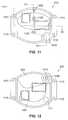
- FIG. 9is a perspective bottom view of the advantageous embodiment of the monitor housing of the physiological condition monitor of the present invention shown in FIG. 8;
- FIG. 10is an exploded perspective top view of the monitor housing of the physiological condition monitor showing the interconnection of the components of the monitor housing;
- FIG. 11is a plan view of the top housing of the monitor housing.
- FIG. 12is a plan view of the bottom of the assembled physiological condition monitor.
- FIG. 13is a cross sectional view of the top housing of the monitor housing taken along line 13 — 13 of FIG. 11;
- FIG. 14is a cross sectional view of the top housing of the monitor housing taken along line 14 — 14 of FIG. 11;
- FIG. 15is a plan view of the bottom housing of the monitor housing.
- FIG. 16is a side elevation view of the bottom housing of the monitor housing taken along line 16 — 16 of FIG. 15;
- FIG. 17is an end elevation view of the bottom housing of the monitor housing taken along line 17 — 17 of FIG. 15;
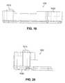
- FIG. 18is a plan view of the battery door of the monitor housing.
- FIG. 19is a side elevation view of the battery door of the monitor housing taken along line 19 — 19 of FIG. 18;
- FIG. 20is an end elevation view of the battery door of the monitor housing taken along line 20 — 20 of FIG. 18;
- FIG. 21is a perspective bottom view of the monitor housing showing the battery door in an open position and showing the placement of a battery in the monitor housing.
- FIGS. 1 through 21, discussed below, and the various embodiments used to describe the principles of the present invention in this patent documentare by way of illustration only and should not be construed in any way to limit the scope of the invention. Those skilled in the art will understand that the principles of the present invention may be implemented in a suitably modified sensor or in a suitably modified physiological condition monitor.
- FIG. 1is a partially cutaway view showing an advantageous embodiment of sensor 100 of the present invention.
- Sensor 100comprises a chamber 120 and a microphone 110 .
- chamber 120comprises a hollow tube having side walls 130 and end walls 140 that form cavity 150 within chamber 120 .
- Cavity 150 of chamber 120is filled with a fluid (not shown).
- the connections between side walls 130 and end walls 140are sealed to prevent the escape of the fluid from cavity 150 .
- the fluidmay be either a liquid or a gas. In most instances the fluid that is used is air.
- the connections between side walls 130 and end walls 140are not hermetically sealed. A small amount of air may pass through the connections between side walls 130 and end walls 140 to adjust for variations in ambient air pressure in the atmosphere.
- Microphone 110is mounted within chamber 120 so that the face 160 of microphone 110 is within the fluid in cavity 150 of chamber 120 .
- Microphone 110may be mounted at any position within chamber 120 .
- microphone 110is mounted within one of the side walls 130 of chamber 120 .
- microphone 110is mounted within one of the end walls 140 of chamber 120 .
- Microphone 110also has microphone output cables, 170 and 180 , for coupling microphone 110 to other electronic equipment (not shown in FIG. 1 or FIG. 2 ).
- the side walls 130 (and end walls 140 ) of chamber 120are constructed of material that is not completely rigid.
- the material used to construct the walls, 130 and 140may be thin metal or plastic. Because the walls, 130 and 140 , are not completely rigid, they are capable of expanding and contracting (i.e., moving inwardly and outwardly) with respect to the interior of cavity 150 of chamber 120 .
- the ability of the walls, 130 and 140 , of sensor 100 to expand and contract in response to the presence of waves of low frequency acoustical energy in chamber 120is a key feature of the present invention.
- acoustical energy from a source(not shown) reaches chamber 120 of sensor 100 the acoustical energy contains both high frequency acoustic signal components and low frequency acoustic signal components.
- the walls 130 and the end walls 140 of chamber 120 of sensor 100expand and contract in response to the presence of the very low frequency acoustic signal components.
- the presence of waves of very low frequency acoustic energy in chamber 120 of sensor 100cause the walls, 130 and 140 , of chamber 120 to expand and contract by extremely small amounts.
- Microphone 110is capable of detecting the low frequency waves of molecules of fluid in chamber 120 that are caused by the low frequency acoustic signal components in the acoustical energy that cause the walls, 130 and 140 , of chamber 120 to expand and contract.
- microphone 110When microphone 110 receives low frequency acoustic signals then microphone 110 generates electronic signals indicative of the intensity of the low frequency acoustic signals.
- Electronic processing circuitsshown in FIGS. 6A, 6 B and 6 C) in a physiological condition monitor 700 (shown in FIG. 7) are coupled to microphone 110 through microphone output cables, 170 and 180 , to receive and analyze the electronic signals that are indicative of the intensity of the low frequency acoustic signals.
- the electronic processing circuitscomprise electronic filters for filtering out all components of the signal that are outside the frequency range of one tenth Hertz (0.1 Hz) to thirty Hertz (30.0 Hz).
- the electronic processing circuitsalso comprise electronic filters for filtering out all components of the signal that are outside the frequency range of one tenth Hertz (0.1 Hz) to two Hertz (2.0 Hz) to obtain a signal indicative of respiration.
- the electronic processing circuitsalso comprise electronic filters for filtering out all components of the signal that are outside the frequency range of ten Hertz (10.0 Hz) to thirty Hertz (30.0 Hz) to obtain a signal indicative of cardiac activity.
- Prior art sensorsdirectly detect higher frequency sounds that are made by the lungs during respiration or by the heart during cardiac activity.
- Sensor 100 of the present inventionobtains information by detecting very low frequency signals caused by the motion of the chest during respiration and by detecting very low frequency signals associated with cardiac activity. Almost all of the noise components in an acoustic signal have frequencies that are above the very low frequency range. Using the method of the present invention to exclude the higher frequencies of sound (and noise), sensor 100 of the present invention eliminates almost all the noise artifacts from the acoustic signal.
- FIG. 3An alternate advantageous embodiment of the present invention is shown in FIG. 3 .
- the embodiment shown in FIG. 3is similar to that shown in FIG. 2 except that chamber 120 of sensor 100 comprises an open ended tube having portions that form an aperture 300 .
- cavity 150 of chamber 120has access to the surrounding atmosphere through aperture 300 in the open end of the tube.
- microphone 110is placed within the end wall 140 of the closed end of the tube.
- microphone 110could be placed within a side wall 130 of an open ended tube. This embodiment shows that it is possible to practice the invention where the fluid in chamber 120 is air that has access to the air of the surrounding environment.
- chamber 120 of sensor 100has been shown in the shape and form of a tube, it is clear that the invention may be practiced with a chamber 120 of sensor 100 that has a different type of shape and form.
- One such alternate embodiment of the present inventionis shown in FIG. 4 .
- FIG. 4shows an exploded view of an alternate advantageous embodiment of sensor 100 of the present invention.
- Sensor 100comprises microphone 110 mounted within chamber 120 .
- Microphone 110may be mounted at any position on the interior surface of the bottom 410 of chamber 120 .
- the shape of chamber 120is rectangular.
- the shape of chamber 120may be circular, elliptical, or of irregular shape.
- the height of the walls 420 of chamber 120are greater than the height of microphone 110 so that the face 160 of microphone 110 is contained within chamber 120 .
- Membrane 430covers the top of chamber 120 .
- Membrane 430has a shape that matches the shape of the top of chamber 120 . In the embodiment of sensor 100 shown in FIG. 4, that shape is rectangular.
- a cavity 440is formed between membrane 430 and walls 420 and bottom 410 of chamber 120 .
- the height of the walls 420are only slightly greater than the height of microphone 110 so that the face 160 of microphone 110 is positioned near membrane 430 .
- membrane 430is made of urethane. However, membrane 430 may also be made of other suitable materials. Before membrane 430 is attached to the top of chamber 120 membrane 430 is slightly stretched. The slight stretching of membrane 430 is to make membrane 430 taut across the top of chamber 120 .
- chamber 120When sensor 100 is used to detect acoustic signals indicative of physiological conditions, chamber 120 is placed next to the body (not shown) of the person whose physiological conditions are being monitored. Chamber 120 is placed with the outer surface of membrane 430 adjacent to a selected area of the body. It is not necessary that membrane 430 touch the skin of the body. There may be a layer of clothing between the skin of the body and membrane 430 . Membrane 430 is thereby acoustically coupled to the area of the body where membrane 430 is placed.
- Membrane 430acquires very low frequency acoustic signals in the form of vibrations from the area of the body to which it is acoustically coupled. That is, as the very low frequency acoustic vibrations from the body impinge upon membrane 430 they cause membrane 430 to vibrate. These vibrations of membrane 430 cause the very low frequency acoustic vibrations to pass into cavity 440 of chamber 120 . The very low frequency acoustic vibrations resonate within the enclosed space of cavity 440 .
- FIG. 5shows a cross sectional view of sensor 100 showing cavity 440 and one possible location for the placement of microphone 110 within cavity 440 .
- Microphone 110detects the very low frequency acoustic vibrations that are resonating within cavity 440 .
- membrane 430 and resonant cavity 440increases the amplitude of the very low frequency acoustic signals from the body so that microphone 110 may more easily detect the signals.
- the interaction of membrane 430 and resonant cavity 440accomplishes this increase in acoustic signal strength by forming an acoustic echo chamber in which membrane 430 acts as a drumhead and resonant cavity 440 acts as a drum.
- the resonance of the very low frequency acoustic signals within resonant cavity 440causes the amplitudes of the acoustic waves within resonant cavity 440 to combine in phase and thereby increase the acoustic signal strength of the acoustic signals that were originally incident on membrane 430 .
- the increase in amplitude of the signals provided by the interaction of membrane 430 and resonant cavity 440enables microphone 110 to efficiently detect signals in the very low frequency range of one tenth Hertz (0.1 Hz) to thirty Hertz (30.0 Hz).
- This very low frequency rangeincludes the very low frequency range used to detect respiration signals (i.e., one tenth Hertz (0.1 Hz) to two Hertz (2.0 Hz)) and the very low frequency range used to detect cardiac information signals (i.e., ten Hertz (10.0 Hz) to thirty Hertz (30.0 Hz)).
- the interaction of membrane 430 and resonant cavity 440assists microphone 110 in detecting very low acoustic signals in the required signal ranges.
- the surface area of membrane 430is larger than the surface area of the face 160 of microphone 110 .
- the surface area of membrane 430is at least five (5) times greater than the surface area of the face 160 of microphone 110 .
- the presence of membrane 430significantly increases the area which may be acoustically coupled to microphone 110 .
- the relatively large area of membrane 430permits larger areas of a body to be analyzed than would otherwise be possible.
- microphone 110When microphone 110 receives low frequency acoustic signals then microphone 110 generates electronic signals indicative of the intensity of the low frequency acoustic signals.
- electronic processing circuits in physiological condition monitor 700are coupled to microphone 110 through microphone output cables, 170 and 180 , to receive and analyze the electronic signals that are indicative of the intensity of the low frequency acoustic signals.
- FIGS. 6A, 6 B and 6 Cillustrate circuit diagrams of an advantageous embodiment of circuitry for processing electrical signals from the microphone of the present invention.
- microphone output cable 180is grounded and microphone output cable 170 is coupled to the positive input of operational amplifier 610 .
- the output of operational amplifier 610is fed back to the negative input of operational amplifier 610 in order to configure operational amplifier 610 as a voltage follower (also known as a buffer amplifier circuit).
- the voltage follower configuration of operational amplifier 610acts as a current amplifier for the signal current from microphone 110 .
- the signal current that is output from operational amplifier 610is an amplified version of the signal current from microphone 110 .
- Operational amplifier 610may be of the type manufactured by Texas Instruments Corporation with product model number TLV2211.
- resistor R 1having a very large value is coupled to the signal line between microphone 110 and operational amplifier 610 .
- the other end of resistor R 1is coupled to a reference voltage V REF .
- a typical value of R 1is one teraohm (1.0 T).
- One teraohmis equal to one million million ohms.
- a very large resistanceis needed to facilitate the signal processing of the very low frequency signals detected by microphone 110 .
- a typical value for reference voltage V REFis one half of the voltage of the power supply battery.
- Operational amplifier 620forms part of low bandpass filter circuit 630 .
- Operational amplifier 620may be of the type manufactured by Texas Instruments Corporation with product model number TLV2211.
- a typical value of capacitor C 1is forty seven hundredths of a microfarad (0.47 ⁇ F).
- One end of resistor R 2is coupled to the signal line between capacitor C 1 and operational amplifier 620 .
- the other end of resistor R 2is coupled to the reference voltage V REF .
- a typical value of R 2is five and one tenth megohms (5.1 M).
- Low bandpass filter circuit 630comprises a double pole switch S 1 for adjusting the value of the resistance that is coupled in parallel with capacitor C 2 .
- both resistor R 5 and resistor R 6are excluded from the circuit.
- Resistor R 5 or resistor R 6 (or both)can be selectively included in the circuit by closing the appropriate pole (or both poles) of switch S 1 .
- a typical value for capacitor C 2is thirty three thousands of a microfarad (0.033 ⁇ F).
- a typical value for resistor R 3is five hundred ten kilohms (510.0 K) and a typical value for resistor R 4 is two megohms (2.0 M).
- a typical value for resistor R 5is one megohm (1.0 K) and a typical value for resistor R 6 is two megohms (2.0 M).
- the output of operational amplifier 620 of low bandpass filter circuit 630appears at the output terminal 640 .
- FIG. 6Billustrates reference voltage generator circuit 660 .
- the output of reference voltage generator circuit 660is the reference voltage V REF .
- the battery voltage V CCis coupled via resistor R 7 to the positive input of operational amplifier 650 .
- Operational amplifier 650forms part of the reference voltage generator circuit 660 .
- Operational amplifier 650may be of the type manufactured by Texas Instruments Corporation with product model number TLV2211. A typical value of resistor R 7 is five and one tenth megohms (5.1 M).
- resistor R 8One end of resistor R 8 is coupled to the signal line between resistor R 7 and operational amplifier 650 . The other end of resistor R 8 is grounded. Capacitor C 3 is coupled in parallel with resistor R 8 . A typical value of resistor R 8 is five and one tenth megohms (5.1 M). A typical value for capacitor C 3 is one hundredth of a microfarad (0.01 ⁇ F).
- the output of operational amplifier 650 of reference voltage generator circuit 660appears at the output terminal 670 as V REF .
- the reference voltage V REFis coupled to the ends of resistor R 1 , resistor R 2 and resistor R 3 as indicated in FIG. 6 A.
- FIG. 6Cshows high bandpass filter circuit 680 .
- High bandpass filter circuit 680comprises operational amplifier 690 .
- Operational amplifier 690may be of the type manufactured by Texas Instruments Corporation with product model number TLV2211.
- resistor R 9One end of resistor R 9 is coupled to the signal line between capacitor C 1 and operational amplifier 620 . The other end of resistor R 9 is coupled to capacitor C 4 .
- a typical value of resistor R 9is thirty three kilohms (33 K).
- a typical value of capacitor C 4is forty seven hundredths of a microfarad (0.47 ⁇ F).
- the output of capacitor C 4is coupled to the negative input of operational amplifier 690 .
- the output of operational amplifier 690is fed back via resistor R 10 to the negative input of operational amplifier 690 .
- the positive input of operational amplifier 690is grounded.
- the A typical value of resistor R 10is thirty three kilohms (33 K).
- the output of operational amplifier 690 of high bandpass filter circuit 680appears at the output terminal 695 .
- the function of high bandpass filter circuit 680may also be accomplished by utilizing digital signal processing methods. For example, the Fast Fourier Transform method may be utilized to perform the function of high bandpass filter 680 .
- FIG. 7is a block diagram of an advantageous embodiment of a physiological condition monitor 700 that utilizes the low frequency microphone sensor 100 of the present invention.
- low frequency microphone sensor 100receives low frequency signals from the body (not shown) of a person whose physiological conditions are being monitored. Low frequency microphone sensor 100 detects and amplifies those signals as previously described.
- Low bandpass filter 710screens out all frequencies except those frequencies in the frequency bandwidth range from one tenth Hertz (0.1 Hz) to two Hertz (2.0 Hz).
- Low bandpass filter 710may comprise conventional electronic filter circuits.
- Low bandpass filter 710may also comprise electronic circuitry that utilizes computer software to achieve the bandpass filter function by digital signal processing.
- the output of low bandpass filter 710is a digitally encoded very low frequency signal representative of the respiration of the person being monitored.
- High bandpass filter 720screens out all frequencies except those frequencies in the frequency bandwidth range from ten Hertz (10.0 Hz) to thirty Hertz (30.0 Hz).
- High bandpass filter 720may comprise conventional electronic filter circuits.
- High bandpass filter 720may also comprise electronic circuitry that utilizes computer software to achieve the bandpass filter function by digital signal processing.
- the output of high bandpass filter 720is a digitally encoded very low frequency signal representative of the cardiac activity of the person being monitored.
- Processor unit 730is capable of receiving digitally encoded signals from low bandpass filter 710 and from high bandpass filter 720 .
- Battery 735is coupled to processor unit 730 and is capable of supplying electrical power for the operation of processor unit 730 . Although battery 735 is shown coupled only to processor unit 730 in FIG. 7, battery 735 is connected to and provides power to all components of physiological condition monitor 700 through other electrical connections (not shown).
- Processor unit 730is capable of detecting a signal from battery 735 that indicates that the voltage level of battery 735 is low.
- processor unit 730is coupled to radio frequency transmitter 740 , which is itself coupled to antenna 750 .
- Processor unit 730is capable of selectively causing radio frequency transmitter 740 to transmit digitally encoded signals from low band pass filter 710 and digitally encoded signals from high band pass filter 720 to base station unit 760 via transmitter 740 and antenna 750 .
- the digitally encoded signalsare received by base station unit 760 via antenna 765 .
- the received signalsmay then be displayed and analyzed at base station unit 760 .
- Processor unit 730is capable of causing radio frequency transmitter 740 to transmit a signal to base station unit 760 that indicates that the voltage level of battery 735 is low. Processor unit 730 is also capable of causing radio frequency transmitter 740 to transmit a signal to base station unit 760 that indicates that processor unit 730 is not receiving signals from low bandpass filter 710 or from high bandpass filter 720 . That is, processor unit 730 can transmit to base station unit 760 a signal indicating that one (or both) of the physiological conditions (breathing and heartbeat) is not being monitored.
- Base station unit 760is capable of sounding an alarm if an analysis of the received signals indicates an abnormal condition in the person being monitored.
- Base station unit 760comprises speaker 767 which may be activated to sound an alarm when base station unit 760 receives one or more signals indicating that (1) the person's breathing is irregular or has stopped, (2) the person's heartbeat is irregular or has stopped, or (3) the person's breathing is not being monitored, or (4) the person's heartbeat is not being monitored, or (5) the battery voltage level is too low.
- Base station 760is to be placed where a care giver who is monitoring base station 760 can hear the alarm whenever the alarm sounds.
- the person's care givercan immediately respond to the alarm to determine what condition exists. If the person is in physiological distress, the person's care giver can immediately attempt to relieve that distress. For example, if the person has ceased breathing, the care giver could immediately administer cardiopulmonary resuscitation (CPR) to the person. If the alarm indicates a low battery or failure of monitoring function, remedial steps can be taken immediately.
- CPRcardiopulmonary resuscitation
- monitor housing 800contains low frequency microphone sensor 100 , low bandpass filter 710 , high bandpass filter 720 , processor unit 730 , battery 735 , transmitter 740 and antenna 750 .
- An advantageous embodiment of monitor housing 800will be described in connection with FIGS. 8 to 21 .
- Monitor housing 800is capable of being coupled to a belt, harness or item of clothing that may be worn by the person being monitored. In this embodiment of physiological condition monitor 700 the movements of the person being monitored are not restricted.
- processor unit 730is coupled to recording device 770 .
- Processor unit 730sends digitally encoded signals from low band pass filter 710 and digitally encoded signals from high band pass filter 720 to recording device 770 .
- Recording device 770is preferably a non-volatile data storage device such as a magnetic tape recorder or a flash memory data storage card.
- a non-volatile data storage deviceis a device that retains the data stored in it when external power to the device is shut off.
- processor unit 730is coupled to network interface unit 780 .
- Network interface unit 780is capable of being coupled to a computer network such as a local area network (LAN), or a wide area network (WAN), or the Internet.
- the connection of network interface unit 780 to a computer networkmay be a wired connection or wireless connection.
- network interface unit 780is shown coupled to the Internet 790 via an Internet protocol router 785 .
- Processor unit 730sends digitally encoded signals from low band pass filter 710 and digitally encoded signals from high band pass filter 720 to network interface unit 780 .
- Network interface unit 780adapts the data to be transmitted via Internet protocol router 785 to the Internet 790 . In this manner the data can be sent to medical monitoring station 795 at a remote location. Medical monitoring station 795 can be located in a hospital, a doctor's office, a clinic, a care giver facility, or any similar type of location.
- processor unit 730is not coupled to transmitter 740 and to antenna 750 .
- processor unit 730is coupled directly by wire to a wired base station unit (not shown) of the type described above.
- the wired base station unitis usually located in a console by the bed or chair of the person being monitored.
- the wired base station unitis capable of displaying and analyzing digitally encoded signals from processor unit 730 .
- the wired base station unitis capable of sounding an alarm if an analysis of the digitally encoded signals indicates an abnormal condition in the person being monitored.
- the wires coupling the physiological condition monitor 700 to the wired base unitdo restrict the movements of the person being monitored.
- FIGS. 8 though 21depict an advantageous embodiment of monitor housing 800 of physiological condition monitor 700 that is shown in FIG. 7 .
- FIG. 8shows a perspective top view of monitor housing 800 .
- FIG. 9shows a perspective bottom view of monitor housing 800 .
- the top half of monitor housing 800comprises a top housing 810 and the bottom half of monitor housing 800 comprises a bottom housing 820 .
- top housing 810 and bottom housing 820fit together to enclose the elements of physiological condition monitor 700 .
- Top housing 810 and bottom housing 820are formed having portions that define a cavity within monitor housing 800 to receive battery 735 that is shown in FIG. 7 .
- battery 735is a flat, cylindrically symmetrical, coin-shaped battery of the type commonly used in cameras and other portable electronic equipment.
- Bottom housing 820is formed having portions that receive a battery door 830 that may be opened and closed to allow access to place and remove battery 735 within the interior of monitor housing 800 .
- Battery door 830is pivotally connected to bottom housing 820 and may be opened and closed by pivotally moving battery door 830 with respect to bottom housing 820 .
- Battery door 830is shown in closed position in FIG. 9 .
- membrane 430 of low frequency microphone sensor 100is also shown in FIG. 9 .
- membrane 430 (and cavity 440 )has an geometrically irregular shape.
- the shapegenerally comprises two curves of different radii spaced apart and bounded on the ends by relatively flat surfaces.
- FIG. 10shows an exploded view of monitor housing 800 .
- Top housing 810has portions that receive a pivotal hinge boss 1010 and allow hinge boss 1010 to rotate.
- Hinge boss 1010pivotally couples battery door 830 to top housing 810 and bottom housing 820 .
- Battery door 830is formed having portions that define a passageway 1020 through battery door 830 for receiving the lower end of hinge boss 1010 . After the lower end of hinge boss 1010 has been placed through passageway 1020 of battery door 830 , retaining ring 1030 fastens battery door 830 to hinge boss 1010 .
- battery 735is shown in position within monitor housing 800 .
- Battery support plate 1040covers the top of battery 735 and only the lower edge of battery 735 is visible in FIG. 10 .
- Two battery retaining pins 1050are placed along the interior of bottom housing 820 to keep battery 735 in its place within monitor housing 800 and to contact the positive and negative terminals of battery 735 .
- Microphone 110 of low frequency microphone sensor 100is shown in FIG. 10 .
- microphone 110is placed through microphone sleeve 1060 .
- microphone 110extends through an aperture 1070 in the bottom of chamber 120 and extends into cavity 440 .
- the interior of chamber 120 and cavity 440are not visible in FIG. 10 .
- Printed circuit board 1080supports the electronic circuitry of physiological condition monitor 700 that has been previously described.
- Lens 1090is provided to permit a signal light such as a light emitting diode (not shown) to send signals concerning the operational status of physiological condition monitor 700 .
- FIG. 11is a plan view of the top housing 810 of monitor housing 800 .
- the location of hinge boss 1010is shown at one corner of top housing 810 .
- the location of lens 1090is also shown.
- the rectangles that are shown in dotted outline in the center of the plan view of top housing 810represent the locations of electronic circuitry (such as processor unit 730 ) that are mounted on underlying printed circuit board 1080 .
- the two circles that are visible in the center of the plan view of top housing 810represent the locations of two receptacles 1120 for receiving fasteners such as screws (not shown) for printed circuit board 1080 to top housing 810 .
- FIG. 12is a plan view of bottom of the assembled monitor housing 800 .
- the location of hinge boss 1010 and retaining ring 1030is shown at one corner of bottom housing 820 .
- Battery door 830is shown in its closed position.
- the locations of four passageways 1110 for receiving fasteners such as screws (not shown) for fastening top housing 810 to bottom housing 820are also shown.
- the rectangles that are shown in dotted outline in the center of bottom housing 820represent the locations of electronic circuitry (such as processor unit 730 ) that are mounted on underlying printed circuit board 1080 .
- the location of microphone 110 within cavity 440is also shown.
- Membrane 430(not shown in FIG. 12) covers the top of cavity 440 .
- FIG. 13is a cross sectional view of top housing 810 of monitor housing 800 taken along line 13 — 13 of FIG. 11.
- a side view of receptacle 1120is shown. Because the line 13 — 13 takes a right angle turn, only one receptacle 1110 is shown.
- FIG. 14is a cross sectional view of top housing 810 of monitor housing 800 taken along line 14 — 14 of FIG. 11 . Both receptacles 1320 are shown. Also shown is the location of hinge boss 1010 .
- FIG. 15is a plan view of bottom housing 820 of monitor housing 800 .
- the location of microphone 110is shown. Also shown in the location and shape of membrane 430 and the underlying cavity 440 (not shown in FIG. 15 ).
- the location of fastener receptacles 1110are also shown.
- the circular area 1510shows the location of battery 735 (not shown in FIG. 15) within monitor housing 800 .
- Oblong area 1520shows the location of battery door 830 (also not shown in FIG. 15 ).
- FIG. 16is a side elevation view of bottom housing 820 of monitor housing 800 taken along line 16 — 16 of FIG. 15. A portion of the bottom of bottom housing 820 is covered with membrane 430 . The location of cavity 440 in bottom housing 820 is shown. Also shown is the location of microphone 110 and fastener receptacles 1110 .
- FIG. 17is an end elevation view of bottom housing 820 of monitor housing 800 taken along line 17 — 17 of FIG. 15 . FIG. 17 also shows the location of membrane 430 , cavity 440 and microphone 110 .
- FIG. 18is a plan view of battery door 830 of monitor housing 800 .
- the shape of battery door 830fits the oblong area 1520 shown in FIG. 15 .
- battery door 830is formed having portions that define a passageway 1020 through battery door 830 for receiving the lower end of hinge boss 1010 . Passageway 1020 is shown in FIG. 18 .
- latch 1810for latching battery door 830 after it has been closed.
- FIG. 19is a side elevation view of battery door 830 of monitor housing 800 taken along line 19 — 19 of FIG. 18 .
- FIG. 20is an end elevation view of battery door 830 of monitor housing 800 taken along line 20 — 20 of FIG. 18 .
- FIG. 21is a perspective bottom view of monitor housing 800 of physiological condition monitor 700 showing battery door 830 in an open position and showing the placement of battery 735 in monitor housing 800 .
- the location of microphone 110 within cavity 440is shown.
- the end of hinge boss 1010 and retaining ring 1030are also shown.
- the present inventionhas been described with reference to monitoring the physiological conditions of human beings, the present invention can also be used to monitor the physiological conditions of vertebrate animals such as cats, dogs, horses, and the like.
Landscapes
- Life Sciences & Earth Sciences (AREA)
- Health & Medical Sciences (AREA)
- Engineering & Computer Science (AREA)
- Physics & Mathematics (AREA)
- Veterinary Medicine (AREA)
- Surgery (AREA)
- Acoustics & Sound (AREA)
- Biomedical Technology (AREA)
- Heart & Thoracic Surgery (AREA)
- Medical Informatics (AREA)
- Molecular Biology (AREA)
- Public Health (AREA)
- Animal Behavior & Ethology (AREA)
- General Health & Medical Sciences (AREA)
- Biophysics (AREA)
- Computer Networks & Wireless Communication (AREA)
- Pathology (AREA)
- Measuring And Recording Apparatus For Diagnosis (AREA)
- Measuring Pulse, Heart Rate, Blood Pressure Or Blood Flow (AREA)
- Measurement Of The Respiration, Hearing Ability, Form, And Blood Characteristics Of Living Organisms (AREA)
Abstract
Description
Claims (33)
Priority Applications (4)
| Application Number | Priority Date | Filing Date | Title |
|---|---|---|---|
| US09/534,813US6575916B2 (en) | 2000-03-24 | 2000-03-24 | Apparatus and method for detecting very low frequency acoustic signals |
| TW090106956ATW541160B (en) | 2000-03-24 | 2001-03-23 | Apparatus and method for detecting very low frequency acoustic signals |
| PCT/US2001/009346WO2001072227A1 (en) | 2000-03-24 | 2001-03-23 | Apparatus and method for detecting very low frequency acoustic signals |
| AU2001255189AAU2001255189A1 (en) | 2000-03-24 | 2001-03-23 | Apparatus and method for detecting very low frequency acoustic signals |
Applications Claiming Priority (1)
| Application Number | Priority Date | Filing Date | Title |
|---|---|---|---|
| US09/534,813US6575916B2 (en) | 2000-03-24 | 2000-03-24 | Apparatus and method for detecting very low frequency acoustic signals |
Publications (2)
| Publication Number | Publication Date |
|---|---|
| US20020156390A1 US20020156390A1 (en) | 2002-10-24 |
| US6575916B2true US6575916B2 (en) | 2003-06-10 |
Family
ID=24131631
Family Applications (1)
| Application Number | Title | Priority Date | Filing Date |
|---|---|---|---|
| US09/534,813Expired - LifetimeUS6575916B2 (en) | 2000-03-24 | 2000-03-24 | Apparatus and method for detecting very low frequency acoustic signals |
Country Status (4)
| Country | Link |
|---|---|
| US (1) | US6575916B2 (en) |
| AU (1) | AU2001255189A1 (en) |
| TW (1) | TW541160B (en) |
| WO (1) | WO2001072227A1 (en) |
Cited By (42)
| Publication number | Priority date | Publication date | Assignee | Title |
|---|---|---|---|---|
| US20030055359A1 (en)* | 2000-03-24 | 2003-03-20 | Ilife Solutions, Inc. | Sensor and method for detecting very low frequency acoustic signals |
| US20030072458A1 (en)* | 1999-09-15 | 2003-04-17 | Ilife Solutions, Inc. | Physiological condition monitors utilizing very low frequency acoustic signals |
| US20030199780A1 (en)* | 2002-04-22 | 2003-10-23 | Page Thomas C. | Device and method for monitoring respiration |
| US20040106960A1 (en)* | 2002-12-02 | 2004-06-03 | Siejko Krzysztof Z. | Phonocardiographic image-based atrioventricular delay optimization |
| US20040127792A1 (en)* | 2002-12-30 | 2004-07-01 | Siejko Krzysztof Z. | Method and apparatus for monitoring of diastolic hemodynamics |
| US20050004609A1 (en)* | 2003-07-02 | 2005-01-06 | Stahmann Jeffrey E. | Implantable devices and methods using frequency-domain analysis of thoracic signal |
| US20050148896A1 (en)* | 2003-12-24 | 2005-07-07 | Siejko Krzysztof Z. | Method and apparatus for third heart sound detection |
| US20050149136A1 (en)* | 2003-12-24 | 2005-07-07 | Siejko Krzysztof Z. | Third heart sound activity index for heart failure monitoring |
| US6984207B1 (en) | 1999-09-14 | 2006-01-10 | Hoana Medical, Inc. | Passive physiological monitoring (P2M) system |
| US20060020295A1 (en)* | 2004-07-23 | 2006-01-26 | Cardiac Pacemakers, Inc. | Method and apparatus for monitoring heart failure patients with cardiopulmonary comorbidities |
| US7011087B1 (en)* | 1999-04-23 | 2006-03-14 | Australian Centre For Advanced Medical Technology Ltd. | Apparatus and method for the treatment of an upper airway flow limitation |
| US20060173363A1 (en)* | 2003-04-03 | 2006-08-03 | Felder Robin A | System and method for passive monitoring of blood pressure and pulse rate |
| US7101339B2 (en) | 2002-12-13 | 2006-09-05 | Cardiac Pacemakers, Inc. | Respiration signal measurement apparatus, systems, and methods |
| US20060253159A1 (en)* | 2005-05-05 | 2006-11-09 | Siejko Krzysztof Z | Trending of systolic murmur intensity for monitoring cardiac disease with implantable device |
| US20060276849A1 (en)* | 2005-06-01 | 2006-12-07 | Cardiac Pacemakers, Inc. | Sensing rate of change of pressure in the left ventricle with an implanted device |
| US20070152812A1 (en)* | 2005-09-21 | 2007-07-05 | Wong Chon M | System and method for active monitoring and diagnostics of life signs using heartbeat waveform and body temperature remotely giving the user freedom to move within its vicinity without wires attachment, gel, or adhesives |
| US7248923B2 (en) | 2003-11-06 | 2007-07-24 | Cardiac Pacemakers, Inc. | Dual-use sensor for rate responsive pacing and heart sound monitoring |
| US20070239218A1 (en)* | 2006-03-29 | 2007-10-11 | Carlson Gerrard M | Hemodynamic stability assessment based on heart sounds |
| US20080119749A1 (en)* | 2006-11-20 | 2008-05-22 | Cardiac Pacemakers, Inc. | Respiration-synchronized heart sound trending |
| US20080125820A1 (en)* | 2006-11-29 | 2008-05-29 | Cardiac Pacemakers, Inc. | Adaptive sampling of heart sounds |
| US20080243014A1 (en)* | 2007-03-28 | 2008-10-02 | Zahra Moussavi | Breathing sound analysis for detection of sleep apnea/popnea events |
| US7559901B2 (en) | 2004-07-28 | 2009-07-14 | Cardiac Pacemakers, Inc. | Determining a patient's posture from mechanical vibrations of the heart |
| US20090312659A1 (en)* | 2005-07-26 | 2009-12-17 | Carlson Gerrard M | Managing preload reserve by tracking the ventricular operating point with heart sounds |
| US7662104B2 (en) | 2005-01-18 | 2010-02-16 | Cardiac Pacemakers, Inc. | Method for correction of posture dependence on heart sounds |
| US7666151B2 (en) | 2002-11-20 | 2010-02-23 | Hoana Medical, Inc. | Devices and methods for passive patient monitoring |
| US20100087890A1 (en)* | 2005-08-19 | 2010-04-08 | Ramesh Wariar | Tracking progression of congestive heart failure via a force-frequency relationship |
| US7736319B2 (en) | 2007-01-19 | 2010-06-15 | Cardiac Pacemakers, Inc. | Ischemia detection using heart sound timing |
| US7883470B2 (en) | 2001-04-11 | 2011-02-08 | Cardiac Pacemakers, Inc. | Apparatus and method for outputting heart sounds |
| US7922669B2 (en) | 2005-06-08 | 2011-04-12 | Cardiac Pacemakers, Inc. | Ischemia detection using a heart sound sensor |
| US20110137195A1 (en)* | 2006-03-01 | 2011-06-09 | Imperial Innovations Limited | Method and Apparatus for Monitoring Respiratory Activity |
| US7962210B2 (en) | 1999-10-20 | 2011-06-14 | Cardiac Pacemakers, Inc. | Implantable medical device with voice responding and recording capacity |
| US8000780B2 (en) | 2006-06-27 | 2011-08-16 | Cardiac Pacemakers, Inc. | Detection of myocardial ischemia from the time sequence of implanted sensor measurements |
| US8108034B2 (en) | 2005-11-28 | 2012-01-31 | Cardiac Pacemakers, Inc. | Systems and methods for valvular regurgitation detection |
| US8306621B2 (en) | 2003-07-02 | 2012-11-06 | Cardiac Pacemakers, Inc. | Cardiac cycle synchronized sampling of impedance signal |
| US8332034B2 (en) | 2007-04-17 | 2012-12-11 | Cardiac Pacemakers, Inc. | Heart sound tracking system and method |
| US8483818B2 (en) | 2005-05-11 | 2013-07-09 | Cardiac Pacemakers, Inc. | Enhancements to the detection of pulmonary edema when using transthoracic impedance |
| US20130289431A1 (en)* | 2004-07-23 | 2013-10-31 | Benjamin Gavish | Apparatus and method for breathing pattern determination using a non-contact microphone |
| US8870791B2 (en) | 2006-03-23 | 2014-10-28 | Michael E. Sabatino | Apparatus for acquiring, processing and transmitting physiological sounds |
| US8972002B2 (en) | 2005-06-01 | 2015-03-03 | Cardiac Pacemakers, Inc. | Remote closed-loop titration of decongestive therapy for the treatment of advanced heart failure |
| US9028407B1 (en) | 2013-12-13 | 2015-05-12 | Safer Care LLC | Methods and apparatus for monitoring patient conditions |
| US9603573B2 (en) | 2014-04-14 | 2017-03-28 | Brain Sentinel, Inc. | Detection of EMG activity using sensors on both sides of the body |
| US10349902B2 (en) | 2014-09-12 | 2019-07-16 | Brain Sentinel, Inc. | Method and apparatus for communication between a sensor and a managing device |
Families Citing this family (5)
| Publication number | Priority date | Publication date | Assignee | Title |
|---|---|---|---|---|
| WO2010083526A2 (en)* | 2009-01-19 | 2010-07-22 | University Of Florida Research Foundation, Inc. | Portable touchless vital sign acquisition device |
| WO2013003908A1 (en)* | 2011-07-06 | 2013-01-10 | Brc Ip Pty Ltd | Pulse sensor measurement system and method |
| CN111879517B (en)* | 2020-08-31 | 2022-02-22 | 合肥工业大学 | Device and method for detecting bearing abrasion in canned motor pump |
| TWI749796B (en) | 2020-09-30 | 2021-12-11 | 瑞軒科技股份有限公司 | Resonance test system and resonance test method |
| CN112816419B (en)* | 2021-01-04 | 2025-07-15 | 中国电子科技集团公司第二十六研究所 | A resonant gas sensor |
Citations (21)
| Publication number | Priority date | Publication date | Assignee | Title |
|---|---|---|---|---|
| US3858575A (en) | 1973-03-05 | 1975-01-07 | Ewald Rose | Body noise detector |
| US4306567A (en) | 1977-12-22 | 1981-12-22 | Krasner Jerome L | Detection and monitoring device |
| US4494553A (en) | 1981-04-01 | 1985-01-22 | F. William Carr | Vital signs monitor |
| US4672976A (en) | 1986-06-10 | 1987-06-16 | Cherne Industries, Inc. | Heart sound sensor |
| US4905706A (en) | 1988-04-20 | 1990-03-06 | Nippon Colin Co., Ltd. | Method an apparatus for detection of heart disease |
| US4934375A (en) | 1988-03-04 | 1990-06-19 | Spectramed, Inc. | Flush-valve assembly for blood pressure measurement catheter |
| US5022402A (en)* | 1989-12-04 | 1991-06-11 | Schieberl Daniel L | Bladder device for monitoring pulse and respiration rate |
| US5086776A (en) | 1990-03-06 | 1992-02-11 | Precision Diagnostics, Inc. | Apparatus and method for sensing cardiac performance |
| US5450854A (en) | 1992-11-24 | 1995-09-19 | Agency Of Industrial Science And Technology | Alpha-wave amplitude selector with window slicer |
| US5550902A (en) | 1994-08-17 | 1996-08-27 | American Telecare, Inc. | Remote stethoscope signal processing system |
| US5564434A (en) | 1995-02-27 | 1996-10-15 | Medtronic, Inc. | Implantable capacitive absolute pressure and temperature sensor |
| US5605156A (en) | 1993-11-17 | 1997-02-25 | Rutgers University | Flexible diaphragm tonometer |
| US5825895A (en)* | 1995-07-21 | 1998-10-20 | Stethtech Corporation | Electronic stethoscope |
| US5989193A (en)* | 1995-05-19 | 1999-11-23 | Somed Pty Limited | Device and method for detecting and recording snoring |
| US6048319A (en) | 1998-10-01 | 2000-04-11 | Integrated Medical Systems, Inc. | Non-invasive acoustic screening device for coronary stenosis |
| US6099486A (en) | 1997-08-20 | 2000-08-08 | Fruscello; John | Precordial monitoring apparatus |
| US6159166A (en)* | 1998-03-20 | 2000-12-12 | Hypertension Diagnostics, Inc. | Sensor and method for sensing arterial pulse pressure |
| US6213955B1 (en) | 1998-10-08 | 2001-04-10 | Sleep Solutions, Inc. | Apparatus and method for breath monitoring |
| US6261237B1 (en) | 1998-08-20 | 2001-07-17 | Medacoustics, Inc. | Thin film piezoelectric polymer sensor |
| US6415033B1 (en)* | 1999-09-15 | 2002-07-02 | Ilife Systems, Inc. | Physiological condition monitors utilizing very low frequency acoustic signals |
| US6416483B1 (en)* | 2000-03-24 | 2002-07-09 | Ilife Systems, Inc. | Sensor and method for detecting very low frequency acoustic signals |
- 2000
- 2000-03-24USUS09/534,813patent/US6575916B2/ennot_activeExpired - Lifetime
- 2001
- 2001-03-23TWTW090106956Apatent/TW541160B/enactive
- 2001-03-23WOPCT/US2001/009346patent/WO2001072227A1/enactiveApplication Filing
- 2001-03-23AUAU2001255189Apatent/AU2001255189A1/ennot_activeAbandoned
Patent Citations (21)
| Publication number | Priority date | Publication date | Assignee | Title |
|---|---|---|---|---|
| US3858575A (en) | 1973-03-05 | 1975-01-07 | Ewald Rose | Body noise detector |
| US4306567A (en) | 1977-12-22 | 1981-12-22 | Krasner Jerome L | Detection and monitoring device |
| US4494553A (en) | 1981-04-01 | 1985-01-22 | F. William Carr | Vital signs monitor |
| US4672976A (en) | 1986-06-10 | 1987-06-16 | Cherne Industries, Inc. | Heart sound sensor |
| US4934375A (en) | 1988-03-04 | 1990-06-19 | Spectramed, Inc. | Flush-valve assembly for blood pressure measurement catheter |
| US4905706A (en) | 1988-04-20 | 1990-03-06 | Nippon Colin Co., Ltd. | Method an apparatus for detection of heart disease |
| US5022402A (en)* | 1989-12-04 | 1991-06-11 | Schieberl Daniel L | Bladder device for monitoring pulse and respiration rate |
| US5086776A (en) | 1990-03-06 | 1992-02-11 | Precision Diagnostics, Inc. | Apparatus and method for sensing cardiac performance |
| US5450854A (en) | 1992-11-24 | 1995-09-19 | Agency Of Industrial Science And Technology | Alpha-wave amplitude selector with window slicer |
| US5605156A (en) | 1993-11-17 | 1997-02-25 | Rutgers University | Flexible diaphragm tonometer |
| US5550902A (en) | 1994-08-17 | 1996-08-27 | American Telecare, Inc. | Remote stethoscope signal processing system |
| US5564434A (en) | 1995-02-27 | 1996-10-15 | Medtronic, Inc. | Implantable capacitive absolute pressure and temperature sensor |
| US5989193A (en)* | 1995-05-19 | 1999-11-23 | Somed Pty Limited | Device and method for detecting and recording snoring |
| US5825895A (en)* | 1995-07-21 | 1998-10-20 | Stethtech Corporation | Electronic stethoscope |
| US6099486A (en) | 1997-08-20 | 2000-08-08 | Fruscello; John | Precordial monitoring apparatus |
| US6159166A (en)* | 1998-03-20 | 2000-12-12 | Hypertension Diagnostics, Inc. | Sensor and method for sensing arterial pulse pressure |
| US6261237B1 (en) | 1998-08-20 | 2001-07-17 | Medacoustics, Inc. | Thin film piezoelectric polymer sensor |
| US6048319A (en) | 1998-10-01 | 2000-04-11 | Integrated Medical Systems, Inc. | Non-invasive acoustic screening device for coronary stenosis |
| US6213955B1 (en) | 1998-10-08 | 2001-04-10 | Sleep Solutions, Inc. | Apparatus and method for breath monitoring |
| US6415033B1 (en)* | 1999-09-15 | 2002-07-02 | Ilife Systems, Inc. | Physiological condition monitors utilizing very low frequency acoustic signals |
| US6416483B1 (en)* | 2000-03-24 | 2002-07-09 | Ilife Systems, Inc. | Sensor and method for detecting very low frequency acoustic signals |
Cited By (103)
| Publication number | Priority date | Publication date | Assignee | Title |
|---|---|---|---|---|
| US7607432B2 (en) | 1999-04-23 | 2009-10-27 | Australian Centre For Advanced Medical Technology Ltd | Apparatus and method for the treatment of an upper airway flow limitation |
| US7011087B1 (en)* | 1999-04-23 | 2006-03-14 | Australian Centre For Advanced Medical Technology Ltd. | Apparatus and method for the treatment of an upper airway flow limitation |
| US6984207B1 (en) | 1999-09-14 | 2006-01-10 | Hoana Medical, Inc. | Passive physiological monitoring (P2M) system |
| US20060063982A1 (en)* | 1999-09-14 | 2006-03-23 | Hoana Medical, Inc. | Passive physiological monitoring (P2M) system |
| US20030072458A1 (en)* | 1999-09-15 | 2003-04-17 | Ilife Solutions, Inc. | Physiological condition monitors utilizing very low frequency acoustic signals |
| US6947565B2 (en)* | 1999-09-15 | 2005-09-20 | Ilife Solutions, Inc. | Physiological condition monitors utilizing very low frequency acoustic signals |
| US7962210B2 (en) | 1999-10-20 | 2011-06-14 | Cardiac Pacemakers, Inc. | Implantable medical device with voice responding and recording capacity |
| US7066894B2 (en)* | 2000-03-24 | 2006-06-27 | Ilife Solutions, Inc. | Sensor and method for detecting very low frequency acoustic signals |
| US20030055359A1 (en)* | 2000-03-24 | 2003-03-20 | Ilife Solutions, Inc. | Sensor and method for detecting very low frequency acoustic signals |
| US8663123B2 (en) | 2001-04-11 | 2014-03-04 | Cardiac Pacemakers, Inc. | Apparatus and method for outputting heart sounds |
| US8905942B2 (en) | 2001-04-11 | 2014-12-09 | Cardiac Pacemakers, Inc. | Apparatus and method for outputting heart sounds |
| US8478391B2 (en) | 2001-04-11 | 2013-07-02 | Cardiac Pacemakers, Inc. | Apparatus and method for outputting heart sounds |
| US8167811B2 (en) | 2001-04-11 | 2012-05-01 | Cardiac Pacemakers, Inc. | Apparatus and method for outputting heart sounds |
| US20110105933A1 (en)* | 2001-04-11 | 2011-05-05 | Avram Scheiner | Apparatus and method for outputting heart sounds |
| US7883470B2 (en) | 2001-04-11 | 2011-02-08 | Cardiac Pacemakers, Inc. | Apparatus and method for outputting heart sounds |
| US7087027B2 (en)* | 2002-04-22 | 2006-08-08 | Page Thomas C | Device and method for monitoring respiration |
| US20030199780A1 (en)* | 2002-04-22 | 2003-10-23 | Page Thomas C. | Device and method for monitoring respiration |
| US7666151B2 (en) | 2002-11-20 | 2010-02-23 | Hoana Medical, Inc. | Devices and methods for passive patient monitoring |
| US20040106960A1 (en)* | 2002-12-02 | 2004-06-03 | Siejko Krzysztof Z. | Phonocardiographic image-based atrioventricular delay optimization |
| US7123962B2 (en) | 2002-12-02 | 2006-10-17 | Cardiac Pacemakers, Inc. | Phonocardiographic image-based atrioventricular delay optimization |
| US7101339B2 (en) | 2002-12-13 | 2006-09-05 | Cardiac Pacemakers, Inc. | Respiration signal measurement apparatus, systems, and methods |
| US8636669B2 (en) | 2002-12-30 | 2014-01-28 | Cardiac Pacemakers, Inc. | Method and apparatus for monitoring of diastolic hemodynamics |
| US20040127792A1 (en)* | 2002-12-30 | 2004-07-01 | Siejko Krzysztof Z. | Method and apparatus for monitoring of diastolic hemodynamics |
| US7972275B2 (en) | 2002-12-30 | 2011-07-05 | Cardiac Pacemakers, Inc. | Method and apparatus for monitoring of diastolic hemodynamics |
| US7691068B2 (en)* | 2003-04-03 | 2010-04-06 | University Of Virginia Patent Foundation | System and method for passive monitoring of blood pressure and pulse rate |
| US20060173363A1 (en)* | 2003-04-03 | 2006-08-03 | Felder Robin A | System and method for passive monitoring of blood pressure and pulse rate |
| US8688214B2 (en) | 2003-07-02 | 2014-04-01 | Cardiac Pacemakers. Inc. | Cardiac cycle synchronized sampling of impedance signal |
| US8306621B2 (en) | 2003-07-02 | 2012-11-06 | Cardiac Pacemakers, Inc. | Cardiac cycle synchronized sampling of impedance signal |
| US7186220B2 (en) | 2003-07-02 | 2007-03-06 | Cardiac Pacemakers, Inc. | Implantable devices and methods using frequency-domain analysis of thoracic signal |
| US20050004609A1 (en)* | 2003-07-02 | 2005-01-06 | Stahmann Jeffrey E. | Implantable devices and methods using frequency-domain analysis of thoracic signal |
| US8442633B2 (en) | 2003-07-02 | 2013-05-14 | Cardiac Pacemakers, Inc. | Cardiac cycle synchronized sampling of impedance signal |
| US8880171B2 (en) | 2003-07-02 | 2014-11-04 | Cardiac Pacemakers, Inc. | Cardiac cycle synchronized sampling of impedance signal |
| US7248923B2 (en) | 2003-11-06 | 2007-07-24 | Cardiac Pacemakers, Inc. | Dual-use sensor for rate responsive pacing and heart sound monitoring |
| US8827919B2 (en) | 2003-12-24 | 2014-09-09 | Cardiac Pacemakers, Inc. | Method and apparatus for third heart sound detection |
| US7431699B2 (en) | 2003-12-24 | 2008-10-07 | Cardiac Pacemakers, Inc. | Method and apparatus for third heart sound detection |
| US20090018461A1 (en)* | 2003-12-24 | 2009-01-15 | Cardiac Pacemakers, Inc. | Method and apparatus for third heart sound detection |
| US9668713B2 (en) | 2003-12-24 | 2017-06-06 | Cardiac Pacemakers, Inc. | Third heart sound activity index for heart failure monitoring |
| US20050148896A1 (en)* | 2003-12-24 | 2005-07-07 | Siejko Krzysztof Z. | Method and apparatus for third heart sound detection |
| US20050149136A1 (en)* | 2003-12-24 | 2005-07-07 | Siejko Krzysztof Z. | Third heart sound activity index for heart failure monitoring |
| US7115096B2 (en) | 2003-12-24 | 2006-10-03 | Cardiac Pacemakers, Inc. | Third heart sound activity index for heart failure monitoring |
| US8500650B2 (en) | 2003-12-24 | 2013-08-06 | Cardiac Pacemakers, Inc. | Third heart sound activity index for heart failure monitoring |
| US8317717B2 (en) | 2003-12-24 | 2012-11-27 | Cardiac Pacemakers, Inc. | Method and apparatus for third heart sound detection |
| US8840563B2 (en) | 2003-12-24 | 2014-09-23 | Cardiac Pacemakers, Inc. | Third heart sound activity index for heart failure monitoring |
| US8211033B2 (en) | 2003-12-24 | 2012-07-03 | Cardiac Pacemakers, Inc. | Third heart sound activity index for heart failure monitoring |
| US20060020295A1 (en)* | 2004-07-23 | 2006-01-26 | Cardiac Pacemakers, Inc. | Method and apparatus for monitoring heart failure patients with cardiopulmonary comorbidities |
| US8065010B2 (en) | 2004-07-23 | 2011-11-22 | Cardiac Pacemakers, Inc. | Method and apparatus for monitoring heart failure patients with cardiopulmonary comorbidities |
| US20130289431A1 (en)* | 2004-07-23 | 2013-10-31 | Benjamin Gavish | Apparatus and method for breathing pattern determination using a non-contact microphone |
| US20090132000A1 (en)* | 2004-07-23 | 2009-05-21 | Cardiac Pacemakers, Inc. | Method and apparatus for monitoring heart failure patients with cardiopulmonary comorbidities |
| US9642557B2 (en)* | 2004-07-23 | 2017-05-09 | 2Breathe Technologies Ltd. | Apparatus and method for breathing pattern determination using a non-contact microphone |
| US7480528B2 (en) | 2004-07-23 | 2009-01-20 | Cardiac Pacemakers, Inc. | Method and apparatus for monitoring heart failure patients with cardiopulmonary comorbidities |
| US7559901B2 (en) | 2004-07-28 | 2009-07-14 | Cardiac Pacemakers, Inc. | Determining a patient's posture from mechanical vibrations of the heart |
| US7951087B2 (en) | 2005-01-18 | 2011-05-31 | Cardiac Pacemakers, Inc. | Method for correction of posture dependence on heart sounds |
| US7662104B2 (en) | 2005-01-18 | 2010-02-16 | Cardiac Pacemakers, Inc. | Method for correction of posture dependence on heart sounds |
| US20080294212A1 (en)* | 2005-05-05 | 2008-11-27 | Cardiac Pacemakers, Inc. | Trending of systolic murmur intensity for monitoring cardiac disease with implantable device |
| US7963926B2 (en) | 2005-05-05 | 2011-06-21 | Cardiac Pacemakers, Inc. | Trending of systolic murmur intensity for monitoring cardiac disease with implantable device |
| US7404802B2 (en) | 2005-05-05 | 2008-07-29 | Cardiac Pacemakers, Inc. | Trending of systolic murmur intensity for monitoring cardiac disease with implantable device |
| US20060253159A1 (en)* | 2005-05-05 | 2006-11-09 | Siejko Krzysztof Z | Trending of systolic murmur intensity for monitoring cardiac disease with implantable device |
| US8483818B2 (en) | 2005-05-11 | 2013-07-09 | Cardiac Pacemakers, Inc. | Enhancements to the detection of pulmonary edema when using transthoracic impedance |
| US8845544B2 (en) | 2005-06-01 | 2014-09-30 | Cardiac Pacemakers, Inc. | Sensing rate of change of pressure in the left ventricle with an implanted device |
| US8007442B2 (en) | 2005-06-01 | 2011-08-30 | Cardiac Pacemakers, Inc. | Sensing rate of change of pressure in the left ventricle with an implanted device |
| US8535235B2 (en) | 2005-06-01 | 2013-09-17 | Cardiac Pacemakers, Inc. | Sensing rate of change of pressure in the left ventricle with an implanted device |
| US20100145403A1 (en)* | 2005-06-01 | 2010-06-10 | Carlson Gerrard M | Sensing rate of change of pressure in the left ventricle with an implanted device |
| US8277389B2 (en) | 2005-06-01 | 2012-10-02 | Cardiac Pacemakers, Inc. | Sensing rate of change of pressure in the left ventricle with an implanted device |
| US8972002B2 (en) | 2005-06-01 | 2015-03-03 | Cardiac Pacemakers, Inc. | Remote closed-loop titration of decongestive therapy for the treatment of advanced heart failure |
| US7670298B2 (en) | 2005-06-01 | 2010-03-02 | Cardiac Pacemakers, Inc. | Sensing rate of change of pressure in the left ventricle with an implanted device |
| US9950175B2 (en) | 2005-06-01 | 2018-04-24 | Cardiac Pacemakers, Inc. | Remote closed-loop titration of decongestive therapy for the treatment of advanced heart failure |
| US20060276849A1 (en)* | 2005-06-01 | 2006-12-07 | Cardiac Pacemakers, Inc. | Sensing rate of change of pressure in the left ventricle with an implanted device |
| US8034000B2 (en) | 2005-06-08 | 2011-10-11 | Cardiac Pacemakers, Inc. | Ischemia detection using a heart sound sensor |
| US7922669B2 (en) | 2005-06-08 | 2011-04-12 | Cardiac Pacemakers, Inc. | Ischemia detection using a heart sound sensor |
| US8758260B2 (en) | 2005-06-08 | 2014-06-24 | Cardiac Pacemakers, Inc. | Ischemia detection using a heart sound sensor |
| US8579828B2 (en) | 2005-07-26 | 2013-11-12 | Cardiac Pacemakers, Inc. | Managing preload reserve by tracking the ventricular operating point with heart sounds |
| US8162844B2 (en) | 2005-07-26 | 2012-04-24 | Cardiac Pacemakers, Inc. | Managing preload reserve by tracking the ventricular operating point with heart sounds |
| US9403017B2 (en) | 2005-07-26 | 2016-08-02 | Cardiac Pacemakers, Inc. | Managing preload reserve by tracking the ventricular operating point with heart sounds |
| US20090312659A1 (en)* | 2005-07-26 | 2009-12-17 | Carlson Gerrard M | Managing preload reserve by tracking the ventricular operating point with heart sounds |
| US8755883B2 (en) | 2005-08-19 | 2014-06-17 | Cardiac Pacemakers, Inc. | Tracking progression of congestive heart failure via a force-frequency relationship |
| US20100087890A1 (en)* | 2005-08-19 | 2010-04-08 | Ramesh Wariar | Tracking progression of congestive heart failure via a force-frequency relationship |
| US20070152812A1 (en)* | 2005-09-21 | 2007-07-05 | Wong Chon M | System and method for active monitoring and diagnostics of life signs using heartbeat waveform and body temperature remotely giving the user freedom to move within its vicinity without wires attachment, gel, or adhesives |
| US7760082B2 (en) | 2005-09-21 | 2010-07-20 | Chon Meng Wong | System and method for active monitoring and diagnostics of life signs using heartbeat waveform and body temperature remotely giving the user freedom to move within its vicinity without wires attachment, gel, or adhesives |
| US8108034B2 (en) | 2005-11-28 | 2012-01-31 | Cardiac Pacemakers, Inc. | Systems and methods for valvular regurgitation detection |
| US20110137195A1 (en)* | 2006-03-01 | 2011-06-09 | Imperial Innovations Limited | Method and Apparatus for Monitoring Respiratory Activity |
| US8920343B2 (en) | 2006-03-23 | 2014-12-30 | Michael Edward Sabatino | Apparatus for acquiring and processing of physiological auditory signals |
| US8870791B2 (en) | 2006-03-23 | 2014-10-28 | Michael E. Sabatino | Apparatus for acquiring, processing and transmitting physiological sounds |
| US11357471B2 (en) | 2006-03-23 | 2022-06-14 | Michael E. Sabatino | Acquiring and processing acoustic energy emitted by at least one organ in a biological system |
| US7938781B2 (en) | 2006-03-29 | 2011-05-10 | Cardiac Pacemakers, Inc. | Hemodynamic stability assessment based on heart sounds |
| US7780606B2 (en) | 2006-03-29 | 2010-08-24 | Cardiac Pacemakers, Inc. | Hemodynamic stability assessment based on heart sounds |
| US20070239218A1 (en)* | 2006-03-29 | 2007-10-11 | Carlson Gerrard M | Hemodynamic stability assessment based on heart sounds |
| US8000780B2 (en) | 2006-06-27 | 2011-08-16 | Cardiac Pacemakers, Inc. | Detection of myocardial ischemia from the time sequence of implanted sensor measurements |
| US8597197B2 (en) | 2006-11-20 | 2013-12-03 | Cardiac Pacemakers, Inc. | Monitoring of heart sounds |
| US8801624B2 (en) | 2006-11-20 | 2014-08-12 | Cardiac Pacemakers, Inc. | Monitoring of heart sounds |
| US20080119749A1 (en)* | 2006-11-20 | 2008-05-22 | Cardiac Pacemakers, Inc. | Respiration-synchronized heart sound trending |
| US10729909B2 (en) | 2006-11-29 | 2020-08-04 | Cardiac Pacemakers, Inc. | Adaptive sampling of heart sounds |
| US20080125820A1 (en)* | 2006-11-29 | 2008-05-29 | Cardiac Pacemakers, Inc. | Adaptive sampling of heart sounds |
| US9700726B2 (en) | 2006-11-29 | 2017-07-11 | Cardiac Pacemakers, Inc. | Adaptive sampling of heart sounds |
| US8096954B2 (en) | 2006-11-29 | 2012-01-17 | Cardiac Pacemakers, Inc. | Adaptive sampling of heart sounds |
| US7736319B2 (en) | 2007-01-19 | 2010-06-15 | Cardiac Pacemakers, Inc. | Ischemia detection using heart sound timing |
| US7559903B2 (en)* | 2007-03-28 | 2009-07-14 | Tr Technologies Inc. | Breathing sound analysis for detection of sleep apnea/popnea events |
| US20080243014A1 (en)* | 2007-03-28 | 2008-10-02 | Zahra Moussavi | Breathing sound analysis for detection of sleep apnea/popnea events |
| US9364193B2 (en) | 2007-04-17 | 2016-06-14 | Cardiac Pacemakers, Inc. | Heart sound tracking system and method |
| US9049981B2 (en) | 2007-04-17 | 2015-06-09 | Cardiac Pacemakers, Inc. | Heart sound tracking system and method |
| US8332034B2 (en) | 2007-04-17 | 2012-12-11 | Cardiac Pacemakers, Inc. | Heart sound tracking system and method |
| US9028407B1 (en) | 2013-12-13 | 2015-05-12 | Safer Care LLC | Methods and apparatus for monitoring patient conditions |
| US9603573B2 (en) | 2014-04-14 | 2017-03-28 | Brain Sentinel, Inc. | Detection of EMG activity using sensors on both sides of the body |
| US10349902B2 (en) | 2014-09-12 | 2019-07-16 | Brain Sentinel, Inc. | Method and apparatus for communication between a sensor and a managing device |
Also Published As
| Publication number | Publication date |
|---|---|
| WO2001072227A1 (en) | 2001-10-04 |
| AU2001255189A1 (en) | 2001-10-08 |
| TW541160B (en) | 2003-07-11 |
| US20020156390A1 (en) | 2002-10-24 |
Similar Documents
| Publication | Publication Date | Title |
|---|---|---|
| US6575916B2 (en) | Apparatus and method for detecting very low frequency acoustic signals | |
| US6415033B1 (en) | Physiological condition monitors utilizing very low frequency acoustic signals | |
| US7066894B2 (en) | Sensor and method for detecting very low frequency acoustic signals | |
| US6369713B1 (en) | System and method for seizing a communication channel in a commercially available child monitor | |
| US6706002B1 (en) | System and method for remotely monitoring at least one physiological characteristic of a child | |
| US6409675B1 (en) | Extravascular hemodynamic monitor | |
| JP5808909B2 (en) | Passive monitoring sensor system using mattress | |
| US9867578B2 (en) | Physiological acoustic monitoring system | |
| US6011477A (en) | Respiration and movement monitoring system | |
| US4738264A (en) | Heart and breathing alarm monitor | |
| US6600949B1 (en) | Method for monitoring heart failure via respiratory patterns | |
| US4657025A (en) | Heart and breathing alarm monitor | |
| US6480733B1 (en) | Method for monitoring heart failure | |
| EP1587422B1 (en) | Apparatus and method for detecting lung sounds using an implanted device | |
| US6527729B1 (en) | Method for monitoring patient using acoustic sensor | |
| US6942622B1 (en) | Method for monitoring autonomic tone | |
| EP0845239A1 (en) | Medical device | |
| US20150045685A1 (en) | Physiological acoustic monitoring system | |
| WO1999004691A1 (en) | Respiration and movement monitoring system | |
| GB2192460A (en) | Movement sensing apparatus | |
| US20240315660A1 (en) | Device and system for detecting sounds from a subject's body | |
| WO2023126950A2 (en) | Devices, systems and methods for detecting and analyzing sounds from a subject's body |
Legal Events
| Date | Code | Title | Description |
|---|---|---|---|
| AS | Assignment | Owner name:ILIFE SYSTEMS, INC., TEXAS Free format text:ASSIGNMENT OF ASSIGNORS INTEREST;ASSIGNORS:HALLECK, MICHAEL E.;HALLECK, MICHAEL D.;LEHRMAN, MICHAEL L.;REEL/FRAME:010998/0449 Effective date:20000531 | |
| AS | Assignment | Owner name:AVATEX CORPORATION, TEXAS Free format text:SECURITY AGREEMENT;ASSIGNORS:ILIFE SYSTEMS, INC.;INFANT TECHNOLOGIES, INC.;HEALTHSENSOR, INC.;AND OTHERS;REEL/FRAME:012852/0187 Effective date:20011219 | |
| AS | Assignment | Owner name:AVATEX CORPORATION, TEXAS Free format text:SECURITY INTEREST;ASSIGNOR:ILIFE SOLUTIONS, INC.;REEL/FRAME:013056/0785 Effective date:20011219 Owner name:ILIFE SOLUTIONS, INC., TEXAS Free format text:ASSIGNMENT OF ASSIGNORS INTEREST;ASSIGNOR:ILIFE SYSTEMS, INC.;REEL/FRAME:013056/0805 Effective date:20011219 | |
| STCF | Information on status: patent grant | Free format text:PATENTED CASE | |
| REMI | Maintenance fee reminder mailed | ||
| FPAY | Fee payment | Year of fee payment:4 | |
| SULP | Surcharge for late payment | ||
| REMI | Maintenance fee reminder mailed | ||
| FPAY | Fee payment | Year of fee payment:8 | |
| SULP | Surcharge for late payment | Year of fee payment:7 | |
| FPAY | Fee payment | Year of fee payment:12 |