US6575753B2 - Firearm laser training system and method employing an actuable target assembly - Google Patents
Firearm laser training system and method employing an actuable target assemblyDownload PDFInfo
- Publication number
- US6575753B2 US6575753B2US09/862,187US86218701AUS6575753B2US 6575753 B2US6575753 B2US 6575753B2US 86218701 AUS86218701 AUS 86218701AUS 6575753 B2US6575753 B2US 6575753B2
- Authority
- US
- United States
- Prior art keywords
- target
- processing system
- assembly
- user
- control
- Prior art date
- Legal status (The legal status is an assumption and is not a legal conclusion. Google has not performed a legal analysis and makes no representation as to the accuracy of the status listed.)
- Expired - Lifetime, expires
Links
- 238000012549trainingMethods0.000titleclaimsabstractdescription97
- 238000000034methodMethods0.000titleclaimsdescription28
- 230000004044responseEffects0.000claimsabstractdescription64
- 238000012546transferMethods0.000claimsabstractdescription10
- 238000012545processingMethods0.000claimsdescription67
- 238000001514detection methodMethods0.000claimsdescription27
- 230000033001locomotionEffects0.000claimsdescription13
- 238000004891communicationMethods0.000claimsdescription9
- 230000008569processEffects0.000claimsdescription3
- 238000009434installationMethods0.000claims2
- 230000000712assemblyEffects0.000abstractdescription82
- 238000000429assemblyMethods0.000abstractdescription82
- 230000003116impacting effectEffects0.000abstractdescription8
- 239000000463materialSubstances0.000description13
- 230000006870functionEffects0.000description12
- 230000005540biological transmissionEffects0.000description9
- 230000000694effectsEffects0.000description9
- 238000010304firingMethods0.000description7
- 238000003780insertionMethods0.000description5
- 230000037431insertionEffects0.000description5
- 230000007246mechanismEffects0.000description5
- CURLTUGMZLYLDI-UHFFFAOYSA-NCarbon dioxideChemical compoundO=C=OCURLTUGMZLYLDI-UHFFFAOYSA-N0.000description4
- 244000309464bullSpecies0.000description3
- 238000010586diagramMethods0.000description3
- 230000001681protective effectEffects0.000description3
- 230000000007visual effectEffects0.000description3
- 230000004913activationEffects0.000description2
- 229910002092carbon dioxideInorganic materials0.000description2
- 239000001569carbon dioxideSubstances0.000description2
- 230000001186cumulative effectEffects0.000description2
- 230000006378damageEffects0.000description2
- 239000005351kimbleSubstances0.000description2
- 238000012986modificationMethods0.000description2
- 230000004048modificationEffects0.000description2
- 239000007787solidSubstances0.000description2
- 230000026676system processEffects0.000description2
- 241001414720CicadellidaeSpecies0.000description1
- 241001465754MetazoaSpecies0.000description1
- BUGBHKTXTAQXES-UHFFFAOYSA-NSeleniumChemical compound[Se]BUGBHKTXTAQXES-UHFFFAOYSA-N0.000description1
- XUIMIQQOPSSXEZ-UHFFFAOYSA-NSiliconChemical compound[Si]XUIMIQQOPSSXEZ-UHFFFAOYSA-N0.000description1
- 208000027418Wounds and injuryDiseases0.000description1
- 230000008859changeEffects0.000description1
- 238000006243chemical reactionMethods0.000description1
- 230000001427coherent effectEffects0.000description1
- 238000004590computer programMethods0.000description1
- 238000005286illuminationMethods0.000description1
- 208000014674injuryDiseases0.000description1
- 230000015654memoryEffects0.000description1
- 230000003287optical effectEffects0.000description1
- 230000008447perceptionEffects0.000description1
- 230000002093peripheral effectEffects0.000description1
- 238000012797qualificationMethods0.000description1
- 238000002310reflectometryMethods0.000description1
- 229910052711seleniumInorganic materials0.000description1
- 239000011669seleniumSubstances0.000description1
- 230000035939shockEffects0.000description1
- 229910052710siliconInorganic materials0.000description1
- 239000010703siliconSubstances0.000description1
- 238000004088simulationMethods0.000description1
- 230000001960triggered effectEffects0.000description1
Images


Classifications
- F—MECHANICAL ENGINEERING; LIGHTING; HEATING; WEAPONS; BLASTING
- F41—WEAPONS
- F41G—WEAPON SIGHTS; AIMING
- F41G3/00—Aiming or laying means
- F41G3/26—Teaching or practice apparatus for gun-aiming or gun-laying
- F41G3/2616—Teaching or practice apparatus for gun-aiming or gun-laying using a light emitting device
- F41G3/2622—Teaching or practice apparatus for gun-aiming or gun-laying using a light emitting device for simulating the firing of a gun or the trajectory of a projectile
- F41G3/2655—Teaching or practice apparatus for gun-aiming or gun-laying using a light emitting device for simulating the firing of a gun or the trajectory of a projectile in which the light beam is sent from the weapon to the target
- F—MECHANICAL ENGINEERING; LIGHTING; HEATING; WEAPONS; BLASTING
- F41—WEAPONS
- F41J—TARGETS; TARGET RANGES; BULLET CATCHERS
- F41J5/00—Target indicating systems; Target-hit or score detecting systems
- F41J5/02—Photo-electric hit-detector systems
- F—MECHANICAL ENGINEERING; LIGHTING; HEATING; WEAPONS; BLASTING
- F41—WEAPONS
- F41J—TARGETS; TARGET RANGES; BULLET CATCHERS
- F41J7/00—Movable targets which are stationary when fired at
- F41J7/04—Movable targets which are stationary when fired at disappearing or moving when hit
Definitions
- the present inventionpertains to firearm training systems, such as those disclosed in U.S. patent application Ser. No. 09/486,342, entitled “Network-Linked Laser Target Firearm Training System” and filed Feb. 25, 2000; Ser. No. 09/761,102, entitled “Firearm Simulation and Gaming System and Method for Operatively Interconnecting a Firearm Peripheral to a Computer System” and filed Jan. 16, 2001; Ser. No. 09/760,610, entitled “Laser Transmitter Assembly Configured For Placement Within a Firing Chamber and Method of Simulating Firearm Operation” and filed Jan. 16, 2001; Ser. No. 09/760,611, entitled “Firearm Laser Training System and Method Employing Modified Blank Cartridges for Simulating Operation of a Firearm” and filed Jan.
- the present inventionpertains to a firearm laser training system employing an actuable target assembly to facilitate firearm training, competitions or other firearm related activities.
- Firearmsare utilized for a variety of purposes, such as hunting, sporting competition, law enforcement and military operations.
- the inherent danger associated with firearmsnecessitates training and practice in order to minimize the risk of injury.
- special facilitiesare required to facilitate practice of handling and shooting the firearm. These special facilities tend to provide a sufficiently sized area for firearm training and/or confine projectiles propelled from the firearm within a prescribed space, thereby preventing harm to the surrounding environment. Accordingly, firearm trainees are required to travel to the special facilities in order to participate in a training session, while the training sessions themselves may become quite expensive since each session requires new ammunition for practicing handling and shooting of the firearm.
- U.S. Pat. No. 2,934,634discloses an attachment for an ordinary firearm which temporarily converts that firearm to a game or practice device. The conversion is achieved by a special target in combination with attachments for the firearm trigger guard and barrel. The target is actuated by a photocell in response to detection of a light ray.
- the barrelincludes an illumination source attached thereto, while the trigger guard has a time delay switch enabling the light source to remain illuminated for a period of time sufficient to assure actuation of the target.
- U.S. Pat. No. 3,526,972discloses a marksman's practicing device for use as an attachment on a shotgun or the like having a casing adapted for attachment to a barrel.
- the casingincludes a light source disposed therein having a trigger-actuated switch to energize the light source to produce a light beam within the casing and a beam directing mechanism for projecting the beam coaxially from the barrel.
- the deviceis employed in connection with a light sensitive target having a bull's eye formed by a selenium cell or the like.
- the cellmay be installed in a stationary position or constructed for movement in a random or flight imitating path, and is connected to an audio visual signal device to indicate a hit upon the target.
- U.S. Pat. No. 3,633,285discloses a laser transmitting device for marksmanship training.
- the deviceis readily mountable to the barrel of a firearm and transmits a light beam upon actuation of the firearm firing mechanism.
- the laser deviceis triggered in response to an acoustical transducer detecting sound energy developed by the firing mechanism.
- the light beamis detected by a target having a plurality of light detectors, whereby an indication of aim accuracy may be obtained.
- U.S. Pat. No. 3,995,376discloses a miniaturized laser assembly mounted on a weapon where the power source and circuitry for the laser assembly are contained within the weapon.
- the laser weaponis fired in a normal manner by squeezing the trigger while aiming at a target.
- the laseremits a harmless invisible signal pulse of coherent light, while a silicon photodiode may be mounted on a stationary, moving, pop-up or personally worn version of the target.
- circuitry connected to the photodiodeenergizes a horn to indicate a successfully aimed and fired shot.
- U.S. Pat. No. 4,048,489discloses a light operated target shooting system.
- An electro-optic light pulse generatoris contained in a gun sight holder and serves as the light source in a light responsive target shooting system.
- the pulse generatoris a laser or other light emitting unit, mounted with an optical system, electronic controls and a battery power source in the interior of the unit.
- the light pulsesare beamed in the direction that the gun and sight holder are pointed.
- the light pulsesare directed toward a target structure including light sensors spaced over the target surface. The sensors provide electrical signals or a change in an electrically sensed circuit parameter that is used to actuate a scoring device.
- U.S. Pat. No. 4,340,370discloses a linear motion and pop-up target training system for training a marksman to fire a simulated weapon.
- the systemincludes a model-board having a terrain surface with six pop-up targets and three bi-directional linear motion targets. Each target emits a pulsed beam of infrared light in response to activation by a first microprocessor computer.
- the weaponincludes a sensor that senses the pulsed infrared beam emitted by the activated target. The sensor supplies an analog signal, proportional to the amount of received light, to a rifle electronics circuit that converts the analog signal to a digital logic signal.
- a second microprocessor computerreceives and processes the digital logic signal in accordance with a predetermined computer program to determine whether the marksman has scored a hit, a miss or a near miss upon the activated target.
- U.S. Pat. No. 4,662,845discloses a target system for laser marksmanship training devices.
- the systemincludes one or more photodetectors mounted on a target and sensitive to one or more pulses of the wavelength of a laser beam simulating the projectile of a weapon.
- An amplifierincreases the power output of the photodetectors, while the amplified signal operates a frequency selective transducer.
- the transduceris attached and acoustically coupled to the target and produces a vibration signature simulating the vibration characteristics of a weapon-fired projectile striking the target.
- a microphone sensitive to the vibration signature of the transduceris acoustically coupled to the target, while a drive mechanism lowers the target out of the field of view of the weapon when the microphone receives a vibration signature from the transducer indicating a hit.
- the related artsuffers from several disadvantages.
- the Hellberg, Sesney and Gianetti systemstypically utilize a stationary target to provide firearm training, thereby limiting those systems with respect to the training scenarios and firearm exercises that may be conducted.
- the Kimble et al and Sumpf systemsmay employ a moving or actuable target, respectively, however, these targets are employed to simulate a flight path of an actual intended target or to indicate a hit via target actuation.
- the targetsprovide specific aspects of firearm training or are employed merely to indicate a hit, and are similarly limited with respect to the training scenarios and firearm exercises that may be conducted.
- the Gallagher et al systemtypically employs a pop-up target utilized for live ammunition, thereby increasing system costs and requiring sufficient space to utilize the targets.
- the Marshall et al systemutilizes a sensor mounted on a firearm, and moving and pop-up targets disposed on a model board that emit light. Accordingly, this system tends to have less accuracy with respect to detecting proper firearm positioning and is limited to the particular scenario presented by the model board. In addition, the systems described above do not generally provide a manner to enable a user to customize and vary the particular training scenario and target sequence or actuation for firearm training.
- Yet another object of the present inventionis to employ an actuable target assembly within a firearm laser training system to conduct various firearm training exercises with varying training scenarios.
- the laser assemblyis attached to an unloaded user firearm to adapt the firearm for compatibility with the training system.
- a useraims an unloaded firearm at a particular target and actuates the firearm trigger to project a laser beam from the laser transmitter assembly toward that target.
- the target assembliesraise and lower targets in accordance with control signals from the computer system.
- the interface unitis connected to the target assemblies and to the computer system parallel port and transmits control signals received from the computer system to the target assemblies.
- the computer systemis connected to a control unit, while the target assemblies are connected to a distribution unit.
- the control unitis typically connected to the computer system parallel port and transmits control signals received from the computer system to the target assemblies via the distribution unit.
- the targetsare raised by corresponding target assemblies at prescribed times for a specific time interval to indicate intended targets for the user, and are lowered in response to the beam impacting the raised targets within that interval (e.g., indicating a hit) or upon expiration of the interval without a beam impact (e.g., indicating a miss).
- the targetis used in conjunction with signal processing circuitry adapted to detect the laser beam.
- a corresponding target assembly control unitanalyzes detection signals from an associated target to lower that raised target in response to beam impact and forwards information to the computer system to provide feedback information to the user via a display.
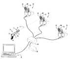
- FIG. 1is a view in perspective of a firearm laser training system having a laser beam directed from a firearm onto an actuable target assembly according to the present invention.
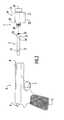
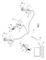
- FIG. 2is an exploded view in perspective and partial section of a laser transmitter assembly of the system of FIG. 1 fastened to a firearm barrel.
- FIG. 3is a schematic block diagram of the firearm laser training system of FIG. 1 .
- FIG. 4is a view in perspective of an interface unit of the system of FIG. 1 .
- FIG. 5is a view in perspective of a power supply of the system of FIG. 1 .
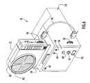
- FIG. 6is a view in perspective of an actuable target assembly of the system of FIG. 1 according to the present invention.
- FIG. 7is a schematic block diagram of the target assembly of FIG. 6 .
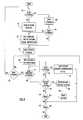
- FIGS. 8-9are procedural flow charts illustrating the manner in which the computer system controls system operation.
- FIGS. 10-12are schematic illustrations of exemplary graphical user screens displayed by the system of FIG. 1 for training activities.
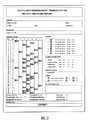
- FIG. 13is an exemplary report generated by the system of FIG. 1 .
- FIG. 14is a schematic illustration of an exemplary graphical user screen displayed by the system of FIG. 1 for a competition event.
- FIG. 15is a view in perspective of an alternative embodiment of the firearm laser training system of FIG. 1 according to the present invention.
- FIG. 16is a schematic block diagram of the firearm laser training system of FIG. 15 .
- FIG. 17is a view in perspective of an actuable target assembly of the system of FIG. 15 .
- FIG. 1A firearm laser training system employing an actuable target assembly according to the present invention is illustrated in FIG. 1 .
- the firearm laser training systemincludes a laser transmitter assembly 2 , actuable target assemblies 10 each having a target 12 , an interface unit 14 and corresponding power supply 26 and a computer system 18 .
- the laser assemblyis attached to an unloaded user firearm 6 to adapt the firearm for compatibility with the training system.
- firearm 6is implemented by a conventional hand-gun and includes a trigger 7 , a barrel 8 , a hammer 9 and a grip 15 .
- Laser assembly 2includes a laser transmitter rod 3 and a laser transmitter module 4 that emits a beam 11 of visible laser light in response to actuation of trigger 7 .
- Rod 3is connected to module 4 and is configured for insertion within barrel 8 to fasten the laser assembly to the barrel as described below.
- a useraims unloaded firearm 6 at a particular target 12 and actuates trigger 7 to project laser beam 11 from laser module 4 toward that target.
- the target assembliesraise and lower targets 12 in accordance with control signals from computer system 18 as described below.
- the targetsare individually raised by corresponding target assemblies 10 at prescribed times for a specified time interval to indicate intended targets for the user, and are lowered in response to the beam impacting the raised targets within that interval (e.g., indicating a hit) or upon expiration of the interval without a beam impact in response to receiving a signal from the computer system to lower the target (e.g., indicating a miss).
- the systemmay be utilized to simulate live ammunition training systems employed by the military or law enforcement, such as the Remote Electronic Target System (RETS).
- RTSRemote Electronic Target System
- the laser training systemmay simulate the view or conditions the trainee encounters in the RETS system, thereby providing angular perception training and angular queuing training (e.g., training to shoot the highest priority threat or closest target).
- the laser systemtypically employs seven targets to simulate the RETS system, but may include any quantity of targets. The targets become raised and/or lowered during the training exercise as described below.
- the systemmay be utilized to simulate firearm competitions, such as the International Practical Shooting Competition (IPSC). The object of this competition is to hit each target in the shortest time interval.
- the laser systemmay simulate this competition and measure the time interval for impacting a series of assembly targets.
- IPCInternational Practical Shooting Competition
- Target 12is used in conjunction with signal processing circuitry adapted to detect the laser beam.
- the targetby way of example, includes a visible circular bull's eye 40 with quadrant dividing lines 42 , and detectors disposed across the target surface to detect the beam.
- a corresponding assembly control unitanalyzes detection signals from the detectors to lower the associated raised target in response to beam impact and forwards information to computer system 18 to provide feedback information to the user via a display (FIGS. 11-12 and 14 ) and/or printer 20 (FIGS. 3 and 13 ).
- the targetmay be scaled to simulate shooting conditions at further distances, such as those within firing ranges, and is similar to the electronic targets disclosed in the above-mentioned patent applications.
- the targetmay utilize masks to display various targets or provide shooting drills (e.g., illustrations of animals with intended target sites, target sites at specific locations or having particular sizes, etc.), such as those disclosed in the aforementioned patent applications.
- the masksmay further be scaled to simulate different distances.
- the systemmay utilize real or simulated “dry fire” type firearms or firearms utilizing modified blank cartridges (e.g., such as those disclosed in the above-mentioned patent applications) for projecting a laser beam to provide full realism in a safe environment.
- laser assembly 2includes laser transmitter rod 3 and laser transmitter module 4 .
- Rod 3includes a generally cylindrical barrel member 17 and a stop 19 disposed at the barrel member distal end.
- the barrel memberis elongated with a tapered proximal end and has transverse cross-sectional dimensions that are slightly less than the cross-sectional dimensions of barrel 8 to enable the barrel member to be inserted within the barrel.
- the barrel membermay be of any shape or size to accommodate firearms of various calibers.
- Adjustable rings 72 , 74are disposed about the barrel member toward its proximal and distal ends, respectively.
- each ringare adjustable to enable barrel member 17 to snugly fit within and frictionally engage barrel 8 in a secure manner.
- Stop 19is in the form of a substantially circular disk having a diameter slightly greater than the cross-sectional dimensions of barrel 8 to permit insertion of rod sections proximal of the stop into the barrel. The stop may alternatively be of any shape or size capable of limiting insertion of the rod into the barrel.
- Barrel member 17is connected to the approximate center of stop 19 , while a post 21 is attached to and extends distally for a slight distance from an approximate center of a stop distal surface.
- Post 21is substantially cylindrical and has transverse cross-sectional dimensions similar to those of barrel member 17 , but may be of any shape or size.
- the postincludes external threads 23 for facilitating engagement with laser module 4 as described below.
- Laser module 4includes a housing 25 having an internally threaded opening 60 defined in an upper portion of a housing rear wall for receiving post 21 and attaching the laser module to rod 3 .
- the housing and openingmay be of any shape or size, while the opening may be defined in the housing at any suitable locations.
- the laser module componentsare disposed within the housing and include a power source 27 , typically in the form of batteries, a mechanical wave sensor 29 and an optics package 31 having a laser (not shown) and a lens 33 . These components may be arranged within the housing in any suitable fashion.
- the optics packageemits laser beam 11 through lens 33 toward target 12 or other intended target in response to detection of trigger actuation by mechanical wave sensor 29 .
- hammer 9impacts the firearm and generates a mechanical wave which travels distally along barrel 8 toward rod 3 .
- mechanical waveor “shock wave” refers to an impulse traveling through the firearm barrel.
- Mechanical wave sensor 29 within the laser modulesenses the mechanical wave from the hammer impact and generates a trigger signal.
- the mechanical wave sensormay include a piezoelectric element, an accelerometer or a solid state sensor, such as a strain gauge.
- Optics package 31 within the laser modulegenerates and projects laser beam 11 from firearm 6 in response to the trigger signal.
- the optics package laseris generally enabled for a predetermined time interval sufficient for the target to detect the beam.
- the beammay be coded, modulated or pulsed in any desired fashion.
- the laser modulemay include an acoustic sensor to sense actuation of the trigger and enable the optics package.
- the laser moduleis similar in function to the laser devices disclosed in the aforementioned patent applications.
- the laser assemblymay be constructed of any suitable materials and may be fastened to firearm 6 at any suitable locations by any conventional or other fastening techniques.
- computer system 18controls system operation and may provide various feedback to a user.
- the computer systemis typically implemented by a conventional IBM-compatible laptop or other type of personal computer (e.g., notebook, desk top, mini-tower, Apple Macintosh, palm pilot, etc.) preferably equipped with display or monitor 34 , a base 32 (i.e., including the processor, memories, and internal or external communication devices or modems) and a keyboard 36 (e.g., including a mouse or other input device).
- Computer system 18includes software to enable the computer system to communicate with and control target assemblies 10 and provide feedback to the user.
- the computer systemmay utilize any of the major platforms (e.g., Linux, Macintosh, Unix, OS2, etc.), but preferably includes a Windows environment (e.g., Windows 95, 98, NT, or 2000). Further, the computer system includes components (e.g. processor, disk storage or hard drive, etc.) having sufficient processing and storage capabilities to effectively execute the system software.
- computer system 18includes a Pentium or compatible processor and at least sixteen megabytes of RAM.
- Computer system 18 and target assemblies 10are connected to interface unit 14 .
- the interface unitis typically connected to power supply 26 and the computer system parallel port and transmits control signals received from the computer system to target assemblies 10 as described below.
- the connections between the interface unit, computer system and target assembliesare preferably implemented by suitable cables. However, the connections may be facilitated in any desired fashion (e.g., wireless, etc.).
- a printer 20may further be connected to the computer system via a switch box 28 (e.g., a separate unit or integrated within the interface unit) to print reports containing user feedback information (e.g., score, hit/miss information, etc.).
- the computer systembasically transmits report information through the switch box to the printer in response to a setting of a selector switch (not shown) disposed on the switch box.
- the switch boxis manipulable by the user and selectively directs information from the computer system parallel port to either the printer or interface unit.
- the switch boxessentially serves as a power or on/off switch where power is enabled when information is directed to the interface unit.
- the interface unit and printermay be connected to various other ports of the computer system (e.g., serial, USB, additional parallel part, etc.) and thereby be utilized without the switch box.
- the interface unitincludes a programmable device or other control circuitry (e.g., microprocessor, logic or other circuitry, etc.) and relays control signals from the computer system to control the target assemblies.
- the computer systemgenerates controls for the target assemblies in accordance with an entered target sequence.
- the control informationtypically includes a command to raise or lower a specific target.
- the computer systemmay control each target assembly individually.
- the control signalsare encoded by the computer system and transmitted to the interface unit through the computer system parallel port.
- the interface unitreceives the encoded signals and decodes them to determine the controls for the individual target assemblies.
- the interface unitchecks the current status of the target assemblies (e.g., may request information from an assembly), and in response to proper status, transmits the control signals to the control units of the appropriate target assemblies.
- the interface unitbasically decodes control signals and disseminates them through the various bits of a transmitted signal.
- the interface unitmay alternatively communicate with the computer system via wireless communication devices.
- the interface unitincludes a housing 37 having the programmable device or control circuitry disposed therein and a front panel.
- the front panelincludes a computer interface connector 39 , a fuse 41 , a light emitting diode (LED) 43 , data receptacles or sockets 45 , motor receptacles or sockets 47 , switch 53 and positive and negative power terminals 49 , 51 .
- Connector 39facilitates connection of the interface unit to a parallel or other port of computer system 18 (FIG. 3 ), while fuse 41 , typically a conventional ten amp fuse, protects the internally housed programmable device and/or circuitry.
- LED 43is typically illuminated to indicate reception of power signals by the interface unit.
- Data receptacles 45receive cables that are connected to the target assemblies and facilitate transmission of power signals and transference of information over the cables between the target assemblies and interface unit.
- Each data receptaclecorresponds to or is associated with a target assembly and, via the cable, provides power signals for target assembly electronics to that target assembly. Further, each data receptacle facilitates transmission and reception of information over the cable between that target assembly and the interface unit.
- the interface unitincludes seven data receptacles.
- Motor receptacles 47receive cables that are connected to the target assemblies and facilitate transmission of power signals over the cables between the target assemblies and interface unit.
- Each motor receptaclecorresponds to or is associated with a target assembly and, via the cable, provides power signals for a target assembly motor to manipulate the target.
- the interface unitincludes seven motor receptacles.
- the cables utilized for connecting the interface unit to the target assembliesmay include a combination of the individual cables compatible with the data and motor receptacles.
- Terminals 49 , 51are connected to the associated terminals of power supply 26 as described below in order to receive power from the power supply.
- the terminalstypically receive power signals in the form of 12V DC. These signals may alternatively be supplied from motorized vehicle electrical systems or any other source providing the appropriate power signals (e.g., battery, etc.).
- the interface unitmay further include receptacles or other interfaces for receiving power signals in the form of 13.8V DC or any other desired voltage.
- Switch 53is manipulable by a user and designates the quantity of hits or beam impacts detected by the target that are required in order to lower a raised target and transmit information to the computer system as described below.
- the switchmay be manipulable toward an identifier (e.g., “S”) to designate that detection of a single beam impact may trigger lowering the raised target and transmission of information, while manipulation of the switch toward another identifier (“D”) designates that two hits are required in order to lower the raised target and transmit information.
- San identifier
- Danother identifier
- the interface unitreceives power from power supply 26 .
- the power supplytypically includes conventional circuitry to provide desired power signals (e.g., 12V DC) and is connected to the interface unit.
- power supply 26includes a housing 44 having circuitry disposed therein and a front panel.
- the front panelincludes positive and negative terminals 46 , 48 , a fuse 50 and a power switch 52 .
- the power switchenables power to the power supply, typically in the form of AC signals, while the fuse protects the internally housed circuitry.
- Terminals 46 , 48are connected to the corresponding interface unit terminals 49 , 51 via cables (not shown) to supply the appropriate power signals to that unit as described above.
- target information associated with that targetis transmitted from the corresponding target assembly to the interface unit.
- This informationmay be in the form of the target status (e.g., raised or lowered).
- the interface unitencodes the information and transmits it to the computer system for processing.
- a target lowered within the prescribed intervalindicates a hit, and the computer system processes the information for display and reports as described below.
- a missis identified when no hit information is received by the computer system from the specified target assembly prior to expiration of the time interval. In this case, the computer system transmits a control signal to that target assembly to lower the target (unless that assembly is active within the next interval of the sequence) and scores a miss.
- a hit targetis lowered by the target assembly control unit as described below.
- the hit informationmay include any type of information to indicate beam impact on a target.
- the targetmay be lowered and hit information provided to the computer system in response to detection of a single hit or two hits (“double tap”) in accordance with the setting of interface unit switch 53 as described above.
- the interface unittypically accommodates a maximum of seven target assemblies, however, the interface unit may be connected to additional interface units in a master/slave arrangement to accommodate an increased quantity of target assemblies.
- a master unitbasically receives control signals from the computer system and transmits the signals to the appropriate slave units accommodating the target assemblies specified in the control signals.
- the master unitmay selectively and individually address the slave units to transmit controls for particular target assemblies.
- the slave control unitsare substantially similar to the master unit, but may include fewer components, thereby reducing costs.
- the master and slave unitsare generally implemented as separate units. Alternatively, the master units may be selectively configured to operate as either a master or slave unit to enable various configurations for controlling any quantity of targets.
- the configurable unitstypically include a switch manipulable by a user to control operation of the unit as a master or a slave.
- the interface unitmay further include appropriate components or be configured to provide sound effect generation, to accommodate additional target assemblies and/or to operate in an event driven manner.
- FIG. 6A target assembly 10 according to the present invention is illustrated in FIG. 6 .
- the target assemblyincludes a housing 54 having a front panel 56 and a movable arm 58 with target 12 attached thereto.
- the housingincludes an assembly motor 84 (FIG. 7) and a control unit or control electronics or circuitry 88 as described below.
- a housing bottom wallincludes a threaded hole (not shown) disposed toward each corresponding bottom wall corner. The holes may receive corresponding feet or may be utilized to mount the target assembly on various support structures (e.g., wall, table, door, etc.) or to affix any attachments as desired.
- Arm 58is disposed adjacent a housing side wall exterior surface and is attached to a shaft (not shown) that extends through the side wall and is coupled to the assembly motor within the housing.
- the armhas an inverted ‘L’ configuration with the target attached to the arm section extending transversely of the housing.
- the motorrotates the shaft, thereby actuating arm 58 to raise or lower target 12 in response to control signals from assembly control electronics 88 as described below.
- Travel of arm 58is controlled by cams (not shown) attached to the shaft which actuate microswitches (not shown) as the arm moves to the end of the desired travel distance.
- the arm movementis considered complete with the arm either in the up or down position depending upon the direction of actuation. This limiting of arm travel may alternatively be accomplished by any conventional or other techniques, and may further include electronic components, such as diodes, to provide fixed or variable speed control of arm movement.
- the housing front panelincludes light emitting diodes (LEDs) 62 , 64 , 66 , a fuse 68 , motor receptacle 47 and data receptacle 45 .
- LED 62is typically yellow and flashes in response to raising of target 12
- LED 64is typically red and is illuminated in response to lowering of the target.
- LED 66is typically green and is illuminated in response to lowering of target 12 upon detection of a hit (e.g., the appropriate quantity of hits or beam impacts).
- LEDs 64 and 66are generally illuminated in response to detection of a hit.
- An additional LEDmay be disposed on the housing front panel and be illuminated to indicate reception of power signals for the assembly motor.
- Fuse 68protects the internally housed control electronics, while motor receptacle 47 is connected to a corresponding interface unit motor receptacle via an appropriate cable and receives power signals for the assembly motor.
- Data receptacle 45is connected to the corresponding interface unit data receptacle via an appropriate cable and receives power signals for the control electronics and facilitates transmission and reception of information between the target assembly and interface unit.
- a housing side wallincludes a connector 70 to facilitate connection, via a connector cable 78 , to a corresponding connector 76 disposed on target 12 in order to supply power signals to the target and facilitate transmission and reception of information between the target and control electronics as described below.
- the target assemblyincludes a motor power supply 80 , limit switches 82 , motor 84 , a relay 86 and control electronics or circuitry 88 .
- the motoractuates arm 58 to raise and lower target 12 and receives power from motor power supply 80 , typically in the form of 12V DC.
- the motor power supplygenerally receives power from the interface unit via the assembly motor receptacle.
- Limit switches 82provide indications of arm position and are utilized to limit movement of the arm within a prescribed angular space.
- Control electronics 88may be implemented by logic or other circuitry and activates relay 86 to control motor 84 .
- the relaymay be implemented by any conventional relays, and typically receives an input power signal of 12V DC.
- the control electronicstransfers power and information signals through connector 76 to target 12 .
- the control electronicsprovides reset, ground and power signals (e.g., 6V DC) to the target, and receives from the target a detection signal in response to detection of a hit.
- the control electronicsreceives power (e.g., 12V DC) and ground signals and information from the interface unit via data receptacle 45 .
- the control electronicsbasically includes an input/output (I/O) port and transfers various signals between the assembly and interface unit.
- the control electronicsmay receive control signals conveying instructions in the form of up/down actuation, assembly reset, double/single hit detection (e.g., quantity of hits to lower a raised target and provide information as described above) and utility functions (e.g., sound effects, etc.).
- the control electronicsgenerally transmits hit detection information to the interface unit via the I/O port. An additional input may be supplied from the control electronics to the interface unit in accordance with a particular application.
- the control electronicsis coupled to interface unit 14 , motor 84 and target 12 , and controls target assembly operation in accordance with control signals from computer system 18 .
- the control electronicsreceives control signals from the interface unit, interprets the control signals and controls the arm to raise the target until the raised target is impacted an appropriate quantity of times by the beam or the computer system directs the control electronics to lower the target due to expiration of the time interval. Further, the control electronics controls target actuation based on the arm position indicated by the limit switch signals as described above. When a time interval for a raised target expires as determined by the computer system, the control electronics receives the appropriate control signals and controls motor 84 to lower the target. In response to the laser beam impacting target 12 , the target sends a signal to the control electronics indicating beam impact.
- the control electronicsdetermines whether or not the appropriate quantity of beam impacts occurred, and if so, controls motor 84 to lower the target.
- the control electronics unitfurther transmits a hit indication to interface unit 14 for forwarding to computer system 18 .
- the time intervals and target sequenceare programmable via computer system 18 to stimulate various scenarios as described below.
- the control electronicsmay further respond to status inquiries of the target assembly by interface unit 14 .
- the target assembliesmay further include appropriate components or be configured to provide sound effect generation, visual light indications and/or response to or indication of other events.
- the target assembliesmay activate any type of devices in response to beam or hit detection in accordance with particular applications (e.g., audio devices, actuators to manipulate objects, visual indicator devices, etc.), and may actuate the targets in response to input signals received from devices detecting events (e.g., audio, motion or other sensors may be utilized to actuate the targets).
- the additional devicesmay be modularly configurable or may be in a fixed configuration, or any combination thereof.
- Computer system 18includes software to control system operation and provide a graphical user interface for displaying user performance and entering information as illustrated in FIGS. 8-9. Initially, the computer system determines the quantity of connected target assemblies and the power level provided to the interface unit at step 61 . If no target assemblies are connected or a low power level is detected as determined at step 63 , an error is indicated or the system switches to a demonstration mode at step 77 . In this mode, system functions are enabled, however, actual transmission and receipt of control signals by the interface unit and associated connections are simulated via software for various purposes (e.g., product demonstration).
- the computer systemdisplays a main or introduction screen at step 65 providing various user options.
- a userindicates to the computer system the desire to manually operate the targets as determined at step 67 , the user may raise and lower, or invert targets via the computer system at step 69 .
- the usermay edit existing shooters or participants, enter additional participants or select a participant at step 73 (e.g., via the screen of FIG. 10 ).
- the procedure to initialize and conduct a sessionis illustrated in FIG. 9 .
- the computer systemdisplays a blank scenario template at step 83 generally including a start identifier, a blank line and an end identifier.
- Each template linemay be edited by the user at step 85 to include desired information.
- a particular target sequenceis entered into the computer system to control the target assemblies.
- the sequencetypically includes the order in which targets 12 are to be raised and the duration for maintaining the targets in a raised state to permit beam impact.
- Each targetmay be individually controlled and selectively specified in the sequence.
- the templatemay include information relating to the target position (up) and corresponding time interval, shooter position (e.g., stand (“off-hand”), lying down (“prone”) or kneeling), the target mask or overlay and range and qualification levels and corresponding scores (e.g., score levels to determine classifications, such as expert, sharp shooter, marksman, not qualified, etc).
- the time interval for each line or targetis accumulated to provide a cumulative time for the scenario.
- the computer systembasically executes instructions on each template line in sequence to provide the scenario.
- a scenario or templateis retrieved or loaded by the computer system in accordance with a user selection at step 109 .
- the scenariomay be modified at step 85 in substantially the same manner described above.
- the computer systemexecutes the template by transmitting control signals to the corresponding target assemblies at appropriate times via interface unit 14 .
- the control signalstypically include information directing the assemblies to raise associated targets for the time interval specified in the template as described above.
- a specified targetWhen a specified target is placed in the raised position, this indicates to the user an intended target. The user subsequently aims firearm 6 at the raised target to project laser beam 11 at that target.
- target 12In response to a beam impact, target 12 provides signals to corresponding control electronics 88 to indicate a hit.
- Control electronics 88provides impact signals (e.g., hit information) to the computer system, and lowers the target in response to a hit.
- impact signalse.g., hit information
- computer system 18determines expiration of the time interval and has not received a signal from the assembly to indicate a hit, a control signal is transmitted to the corresponding assembly control electronics to lower the target and a miss is recorded.
- Computer system 18receives the impact information from the target assemblies and calculates a corresponding score.
- the scoremay be based on the time required to hit a target and/or distances between the user and the target or other user defined criteria.
- the target informationmay include location information of beam impact (e.g., x and y coordinates) to determine scores based on proximity of the beam impact to an intended target site.
- computer system 18may provide the scores on a graphical user screen as described below.
- Exemplary screens providing scoring and other informationare illustrated in FIGS. 11-12. These screens typically provide the target sequence including the particular target, the time interval of raised status (T), the lane of the target (L), and target status (S). In addition, these screens generally provide a hit or miss indication along with ranges, scoring and other information.
- a report containing similar information relating to performance of a usermay be printed by printer 20 and is illustrated, by way of example only, in FIG. 13 . It is to be understood that the screens and report may be arranged in any fashion and include any types of information.
- a scenariois complete, several options are available to the user. If the user desires to conduct the same scenario as determined at steps 91 and 93 , the scenario is repeated at step 89 . When a different scenario is desired, a new scenario may be created or loaded in substantially the same manner described above.
- the computer systemsaves the session or shooter performance in a user specified or predetermined file. If the user desires to reload or view a saved session as determined at step 99 , the computer system retrieves a user specified session at step 101 for display on a graphical user screen as described above. When a report is desired by the user as determined at step 103 , the computer system prints the report at step 105 as described above. The above process continues until the user indicates completion as determined at step 107 .
- the systemmay be utilized to simulate a RETS range utilized in military or law enforcement training as described above or to simulate a competition event, such as IPSC.
- the targetmay be configured to present any type of graphic to simulate conventional targets for these or other types of activities (e.g., E-type Silhouette, military pop-up targets, plates, etc.).
- An IPSC eventtypically utilizes five targets (e.g., plates) that are simultaneously raised. The object is to hit each target in the shortest cumulative time interval.
- the systemmay utilize five target assemblies, while computer system 18 may include a sequence or scenario template to control the target assemblies in a manner similar to the competition.
- the computer systemfunctions as described above to control the target assemblies, and measures the time interval for a user to hit each target or all targets.
- the resultsmay be displayed or printed by computer system 18 as described above.
- An exemplary display for an IPSC competitionis illustrated in FIG. 14, however, the display may be arranged in any fashion and include any types of information.
- FIGS. 1-7Operation of the system is described with reference to FIGS. 1-7.
- user information and a target sequenceare entered into computer system 18 via graphical user screens (e.g., FIG. 10) as described above.
- the systemmay accommodate any sequence for any quantity of target assemblies (e.g., at least one).
- Laser transmitter rod 3is connected to laser module 4 and inserted into barrel 8 of firearm 6 as described above.
- the laser moduleis actuated in response to depression of firearm trigger 7 .
- Any of the lasers or firearms disclosed in the above-mentioned patent applicationsmay be utilized (e.g., systems employing dry fire or modified blank cartridges).
- the target assembliesare arranged in a desired configuration and computer system 18 is commanded to control the target assemblies in accordance with the entered sequence or scenario template.
- the useraims the firearm and projects a laser beam at that target.
- a raised targetis impacted an appropriate quantity of times within the specified time interval, the target is lowered and hit information is transmitted to the computer system as described above.
- a hitis indicated by the target assembly indicators (LEDs) as described above. If the beam does not impact a raised target within the specified time interval, the target is lowered in response to control signals from the computer system as described above and the computer system scores a miss.
- the computer systemreceives the hit information and provides feedback information to the user in the form of graphical user screens (e.g., FIGS. 11-12) and/or a printed report (e.g., FIG. 13) as described above.
- the systemmay simulate a competition, such as IPSC, where the computer system measures the time interval required to hit each of successive targets.
- IPSCa competition
- the systemoperates as described above, and further provides the measured time interval on a display (FIG. 14) or printed report.
- the firearm laser training systemincludes a laser transmitter assembly 2 , actuable target assemblies 110 each having a target 12 , a distribution unit 114 , a control unit 116 and a computer system 18 .
- the laser assemblyis attached to an unloaded user firearm 6 to adapt the firearm for compatibility with the training system.
- the firearm, laser transmitter assembly, target and computer systemare each as described above.
- a useraims unloaded firearm 6 at a particular target 12 and actuates trigger 7 to project laser beam 11 from laser module 4 toward that target.
- the target assembliesraise and lower targets 12 in accordance with control signals from computer system 18 as described below.
- the targetsare individually raised by corresponding target assemblies 110 at prescribed times for a specific time interval to indicate intended targets for the user, and are lowered in response to the beam impacting the raised targets within that interval (e.g., indicating a hit) or upon expiration of the interval without a beam impact in response to a signal from the computer system to lower the target (e.g., indicating a miss).
- Target 12is used in conjunction with signal processing circuitry adapted to detect the laser beam and, by way of example, includes a visible circular bull's eye 40 with quadrant dividing lines 42 , and detectors disposed across the target surface to detect the beam as described above.
- a corresponding assembly control unitanalyzes detection signals from the detectors to lower the associated raised target in response to beam impact and forwards information to computer system 18 to provide feedback information to the user via a display (FIGS. 11-12 and 14 ) and/or printer 20 (FIGS. 14 and 16) as described above.
- control unit 116is typically connected to the computer system parallel port and transmits control signals received from the computer system to target assemblies 110 via the distribution unit as described below.
- the connections between the control unit, distribution unit, computer system and target assembliesare preferably implemented by suitable cables.
- a printer 20may further be connected to control unit 116 to print reports containing user feedback information (e.g., score, hit/miss information, etc.).
- the computer systembasically transmits the report information through the control unit to the printer via a separate or integrated control unit selector switch (not shown).
- the switchis manipulable by the user and selectively directs information from the control unit to either the printer or distribution unit.
- the switchessentially serves as a power or on/off switch where power is enabled when information is directed to the distribution unit.
- the control unitincludes a conventional or commercially available programmable device (e.g., microprocessor, gate array, etc.) or other control circuitry (e.g., combinational logic, etc.), and relays control signals from the computer system to control the target assemblies.
- the computer systemgenerates controls for the target assemblies in accordance with an entered target sequence.
- the control informationtypically includes a command to raise or lower a specific target.
- the computer systemmay control each target assembly individually.
- the control signalsare encoded by the computer system and transmitted to the control unit through the computer system parallel port.
- the control unitreceives the encoded signals and decodes them to determine the controls for the individual target assemblies.
- the control unitchecks the current status of the target assemblies (e.g., may request information from an assembly), and in response to proper status, transmits the control signals to distribution unit 114 .
- the distribution unitreceives the control signals and forwards them to the control units of the appropriate target assemblies.
- the control unitbasically decodes control signals and disseminates them through the various bits of a transmitted signal.
- target information associated with that targetis transmitted from the corresponding target assembly to the distribution unit.
- the distribution unitforwards the information to the control unit.
- This informationmay be in the form of the target status (e.g., raised or lowered).
- the control unitencodes the information and transmits it to the computer system for processing.
- a target lowered within the prescribed intervalindicates a hit, and the computer system processes the information for display and reports as described above.
- a hit targetis lowered by the target assembly control unit as described below.
- the hit informationmay include any type of information to indicate beam impact on a target.
- the control unittypically accommodates a maximum of seven target assemblies, however, the control unit may be connected to additional control units (e.g., up to three or more units) in a master/slave arrangement to accommodate an increased quantity of target assemblies.
- the master unitbasically receives control signals from the computer system and transmits the signals to the appropriate slave units accommodating the target assemblies specified in the control signals.
- the slave control unitsare substantially similar to the master unit, but may include fewer components (e.g., be constructed without the parallel port, printer port or power supply), thereby reducing costs.
- FIG. 17A target assembly 110 according to the present invention is illustrated in FIG. 17 .
- the target assemblyincludes a frame 150 , an assembly control unit 152 , a motor 154 , a power source or battery 156 and a movable arm 158 having target 12 attached thereto.
- Frame 150includes a base 162 and a side wall 164 , each having a generally rectangular configuration.
- the side wallis substantially perpendicular to the base having its bottom edge joined to a base side edge.
- a handle 166is attached to and transversely extends from an upper edge of the side wall interior surface, while legs 168 are attached to and extend from the front and rear lower sections of the side wall to provide stability for the target assembly.
- the legseach include an elongated bar 170 having a foot 176 disposed at the bar distal end.
- the baseincludes assembly control unit 152 , motor 154 and power source 156 mounted thereon.
- Arm 158is disposed adjacent the side wall exterior surface and is attached to a shaft (not shown) that extends through the side wall and is coupled to motor 154 .
- the armhas an inverted ‘L’ configuration with the target attached to the arm section extending substantially parallel to the base.
- the motorrotates the shaft, thereby actuating arm 158 to raise or lower target 12 in response to control signals from assembly control unit 152 .
- a series of switchesare disposed toward the upper edge of the side wall exterior surface to control arm actuation, while a plurality of stops 178 are disposed in the path of arm movement, via a corresponding bracket 180 mounted to the side wall exterior surface, to limit motion of the arm and target.
- a pair of camsare disposed on the shaft adjacent side wall 164 , and are configured to toggle the switches during arm movement. The switches provide signals to assembly control unit 152 to indicate the location of the arm within its motion path, thereby enabling the assembly control unit to control motor 154 accordingly.
- Assembly control unit 152is connected to distribution unit 114 , motor 154 , power source 156 , target 12 and the switches via suitable cables, and controls target assembly operation in accordance with control signals from computer system 18 .
- the assembly control unitincludes control circuitry (e.g., processor, logic circuits, etc.) and receives control signals from the distribution unit.
- the assembly control unitinterprets the control signals and controls the arm to raise the target for the specified time interval, or until the raised target is impacted by the beam. Further, the assembly control unit controls target actuation based on the arm position indicated by the switch signals as described above. When a time interval for a raised target expires as determined by the computer system, the assembly control unit controls motor 154 to lower the target in response to control signals from computer system 18 .
- the targetIn response to the laser beam impacting target 12 , the target sends a signal to the control unit indicating beam impact.
- the control unitcontrols motor 154 to lower the target.
- the assembly control unitfurther transmits a hit indication to distribution unit 114 for forwarding to computer system 18 .
- the hit informationmay include the raised or lowered status of the target to enable the computer system to determine the presence of a hit as described above.
- the time intervals and target sequenceare programmable via computer system 18 to stimulate various scenarios as described above.
- the assembly control unitmay further respond to status inquiries of the target assembly by control unit 116 .
- assembly control unit 152includes a series of indicators, preferably in the form of light emitting diodes (LED), to indicate the status of the target.
- the assembly control unit housingincludes three indicators arranged in vertical relation. An uppermost indicator (e.g., red) indicates target 12 in a raised position, while a central indicator (e.g., green) indicates the beam impacting target 12 . This indicator remains illuminated until a successive raising and lowering of the target. A lowermost indicator indicates target 12 in a lowered position.
- a target power switchcontrols power to assembly control unit 152 .
- the alternative systemfunctions in substantially the same manner as the system described above, except that control signals and other information are transmitted between the target assemblies and computer system via the control and distribution units.
- computer system 18 of the alternative systemincludes software to control system operation and provide a graphical user interface for displaying user performance and entering information in substantially the same manner as the system described above.
- the alternative systemmay similarly be utilized to simulate a RETS range utilized in military or law enforcement training as described above or to simulate a competition event, such as IPSC.
- the targetmay be configured to present any type of graphic to simulate conventional targets for these or other types of activities (e.g., E-type Silhouette, military pop-up targets, plates, etc.).
- FIGS. 15-17Operation of the alternative system is described with reference to FIGS. 15-17.
- user information and a target sequenceare entered into computer system 18 via graphical user screens (e.g., FIG. 10) as described above.
- the systemmay accommodate any sequence for any quantity of target assemblies (e.g., at least one).
- Laser transmitter rod 3is connected to laser module 4 and inserted into barrel 8 of firearm 6 as described above.
- the laser moduleis actuated in response to depression of firearm trigger 7 .
- the target assembliesare arranged in a desired configuration and computer system 18 is commanded to control the target assemblies in accordance with the entered sequence. As each target 12 is raised, the user aims the firearm and projects a laser beam at that target.
- the targetWhen a raised target is impacted within the specified time interval, the target is lowered and hit information is transmitted to the computer system as described above. In addition, a hit is indicated by the control unit indicator (LED) as described above. If the beam does not impact a raised target within the specified time interval, the target is lowered in response to control signals from the computer system as described above.
- the computer systemreceives the hit information and provides feedback information to the user in the form of graphical user screens (e.g., FIGS. 11-12) and/or a printed report (e.g., FIG. 13) as described above.
- the systemmay simulate a competition, such as IPSC, where the computer system measures the time interval required to hit each of successive targets.
- IPSCa competition
- the systemoperates as described above, and further provides the measured time interval on a display (FIG. 14) or printed report.
- the systemsmay include any quantity of target assemblies arranged in any desired fashion.
- the computer systemmay be implemented by any conventional or other computer or processing system, and may control the target assemblies to operate in any desired scenario or target sequence.
- the computer systemmay be directly or indirectly connected to the target assemblies via any communications mechanisms.
- the components of the systemsmay be connected by any communications or other devices (e.g., cables, wireless, network, etc.) in any desired fashion.
- the computer systemmay be in communication with other training systems via any type of communications medium (e.g., direct line, telephone line/modem, network, etc.) to facilitate group training or competitions.
- the systemsmay be configured to simulate any types of training or competition scenarios.
- the printermay be implemented by any conventional or other type of printer.
- the systemsmay raise any quantity of targets simultaneously to provide multiple targets for a user.
- the functions of the various components of the systemsmay be distributed among any quantity of existing or additional components in any desired fashion.
- the firearm laser training systemsmay be utilized with any type of actual or simulated firearm (e.g., hand-gun, rifle, shotgun, machine gun, powered by air/carbon dioxide, etc.), while the laser module may be fastened to the firearm at any suitable locations via any conventional or other fastening techniques (e.g., frictional engagement with the barrel, brackets attaching the device to the firearm, etc.).
- the systemsmay include a dummy firearm projecting a laser beam, or replaceable firearm components (e.g., a barrel) having a laser device disposed therein for firearm training.
- the replaceable componentse.g., barrel
- the replaceable componentsmay further enable the laser module to be operative with a firearm utilizing any type of blank cartridges.
- the laser assemblymay include the laser module and rod or any other fastening device.
- the laser modulemay emit any type of laser beam within suitable safety tolerances.
- the laser module housingmay be of any shape or size, and may be constructed of any suitable materials.
- the openingmay be defined in the module housing at any suitable locations to receive the rod.
- the housing and rodmay include any conventional or other fastening devices (e.g., integrally formed, threaded attachment, hook and fastener, frictional engagement with the opening, etc.) to attach the module to the rod.
- the optics packagemay include any suitable lens for projecting the beam.
- the laser beammay be enabled for any desired duration sufficient to enable the target to detect the beam.
- the laser modulemay be fastened to a firearm or other similar structure (e.g., a dummy, toy or simulated firearm) at any suitable locations (e.g., external or internal of a barrel) and be actuated by a trigger or any other device (e.g., power switch, firing pin, relay, etc.).
- the laser modulemay be configured in the form of ammunition for insertion into a firearm firing or similar chamber and project a laser beam in response to trigger actuation.
- the laser modulemay be configured for direct insertion into the barrel without the need for the rod.
- the laser modulemay include any type of sensor or detector (e.g., acoustic sensor, piezoelectric element, accelerometer, solid state sensors, strain gauge, etc.) to detect mechanical or acoustical waves or other conditions signifying trigger actuation.
- the laser module componentsmay be arranged within the housing in any fashion, while the module power source may be implemented by any type of batteries.
- the modulemay include an adapter for receiving power from a common wall outlet jack or other power source.
- the laser beammay be visible or invisible (e.g., infrared), may be of any color and may be modulated in any fashion (e.g., at any desired frequency or unmodulated) or encoded to provide any desired information.
- the laser transmitter rodmay be of any shape or size, and may be constructed of any suitable materials.
- the rodmay include dimensions to accommodate any firearm caliber.
- the ringsmay be of any shape, size or quantity and may be constructed of any suitable materials.
- the ringsmay be disposed at any locations along the rod and may be implemented by any devices having adjustable dimensions.
- the stopmay be of any shape or size, may be disposed at any suitable locations along the rod and may be constructed of any suitable materials.
- the postmay be of any shape or size, may be disposed at any suitable locations on the rod, and may be constructed of any suitable materials.
- the post or rodmay include any conventional or other fastening devices to attach the laser module to the rod.
- the targetmay be implemented by any of the electronic targets described in the aforementioned patent applications, or any device that can detect laser beam impact.
- the targetmay be configured and/or include any types of detectors to detect any energy medium having any modulation, pulse or frequency.
- the lasermay be implemented by a transmitter emitting any suitable energy wave.
- the targetmay be of any shape or size, include any laser detecting circuitry, and present any type of conventional or other target configurations.
- the targetmay include any conventional or other fastening devices to attach a mask to the target.
- the masksmay be of any shape or size, may be disposed on the target at any suitable locations and may be constructed of any suitable materials (e.g., may be transparent, translucent, opaque or any combination or degrees thereof).
- the masksmay include any conventional or other fastening devices for attachment to the target.
- the masksmay include any illustration and/or configuration having openings or slots of any shape, size or quantity defined at any suitable locations for training in any types of firearm activities.
- the masks and targetsmay be scaled in any fashion to simulate any desired distances.
- the interface unitmay accommodate any quantity of target assemblies and may include any type of conventional or other processor or circuitry to provide the above-described functions.
- the housingmay be of any shape or size and be constructed of any suitable materials.
- the interface unitmay be connected to any port of the computer system (e.g., parallel, USB, serial, etc.), and may include any quantity of any type of connectors disposed at any suitable locations to connect to the computer system.
- the interface unitmay communicate with the computer system via any suitable medium (e.g., cables, wires, network, wireless, etc.) and transfer any desired information.
- the control signals and other informationmay be encoded by or for compatibility with the computer system in any desired fashion.
- the computer system and other control signalsmay include any types of information or commands to control the target assemblies in any fashion.
- the control signals and other informationmay be formatted in any desired fashion for transmission between the computer system and target assemblies.
- the switchmay be implemented by any conventional switches or circuitry and may designate and enable the system to utilize any quantity of beam impacts to indicate a hit.
- the switchmay utilize any quantity of any type of identifiers to indicate a beam impact quantity.
- the fusemay be implemented by any conventional or other fuse or protective device.
- the motor and data receptaclesmay include any suitable configurations to transmit and/or receive signals.
- the interface unitmay include any quantity of the motor and data receptacles disposed at any suitable locations.
- the interface unitmay include any quantity of any types of terminals or other interfaces to receive power signals from any power source (e.g., power supply, battery, vehicle electrical system, generator, etc.).
- the cables utilized for communication between the interface unit and target assembliesmay be of any quantity, may include any quantity of individual cables in any combination and may be compatible with any suitable receptacles or sockets.
- the interface unit componentsmay
- the switch boxmay be implemented by any conventional or other switching circuitry.
- the printer and interface unitmay be connected to the computer system via different ports, thereby obviating the need to use the switch box. Further, the systems may be utilized without a printer.
- the interface unit power supply housingmay be of any shape or size and may be constructed of any suitable materials.
- the power switchmay be implemented by any conventional switches or circuitry, while the fuse may be implemented by any conventional or other fuse or protective device.
- the power supplymay include any quantity of any types of terminals or other interfaces to supply power signals of any desired voltage.
- the power supply componentse.g., switch, terminals, fuse, etc.
- the target assembly housing and structural componentsmay be of any shape or size, and may be constructed of any suitable materials.
- the motormay be implemented by any suitable motor or driver, while the motor power supply may be implemented by any conventional or other power supply to provide appropriate power signals to the motor.
- the relaymay be implemented by any type of conventional or other relay and utilize any input voltage.
- the limit switchesmay be implemented by any conventional switches or circuitry, while the fuse may be implemented by any conventional or other fuse or protective device.
- the motor and data receptaclesmay include any suitable configurations to transmit and/or receive signals.
- the target assemblymay include any quantity of the motor and data receptacles disposed at any suitable locations.
- the targetmay be attached to the arm via any conventional fastening techniques.
- the threaded holesmay be defined in the assembly at any suitable locations.
- the assembly componentsmay be implemented by any conventional or other components performing the described functions and may be arranged within the housing in any desired fashion.
- the armmay be of any shape or size, may be constructed of any suitable materials and may be attached to the shaft or directly to the motor.
- the armmay be disposed on the target assembly at any desired location and be actuated in any desired direction.
- the target and target assemblymay be connected via any quantity of any type of cable, and may include any quantity of any types of connectors disposed at any suitable locations.
- the target assemblymay transmit and receive any desired information to and from the target and interface unit.
- the target assemblymay include any quantity of any type of indicators (e.g., LED) of any shape, size or color to indicate target status (e.g., raised, lowered, hit or miss, etc.).
- the indicatorsmay be illuminated in any fashion (e.g., flash at any desired rate) and be disposed at any suitable locations on the target assembly.
- the target assemblymay be configured to accommodate and actuate any quantity of targets either individually or in any combination.
- the assembly control electronicsmay include any conventional or other processor or circuitry to control assembly operation.
- the software for the various processors and/or computer systemsmay be implemented in any desired computer language and could be developed by one of ordinary skill in the computer arts based on the functional descriptions contained herein and flow charts illustrated in the drawings.
- the processors and/or computer systemsmay alternatively be implemented by hardware or other processing circuitry.
- the display screens and reportsmay be arranged in any fashion and contain any type of information.
- the systemsmay produce any desired type of display or report having any desired information.
- the computer systemmay determine scores based on any desired criteria.
- the various functions of the processors and computer systemmay be distributed in any manner among any quantity of processing systems or circuitry.
- the flow charts and/or algorithms described abovemay be modified in any manner capable of performing the functions described herein.
- the systemmay be employed without a computer system where the interface unit or target assemblies raise and lower the targets using time intervals selected by a user via a timing device (e.g., rotary switch, etc.).
- control software and/or processorsmay be integrated in to the interface unit and/or target assemblies to obviate the need for an external computer system.
- the templatesmay include any desired information and control the target assemblies to perform any scenario or sequence.
- the target assembliesmay raise the targets for any desired time interval.
- the templatesmay include any desired format and each line may be executed in any desired order.
- the alternative target assembly structural componentsmay be of any shape or size, and may be constructed of any suitable materials.
- the motormay be implemented by any suitable motor or driver.
- the targetmay be attached to the arm via any conventional fastening techniques.
- the legs and stoppersmay be attached to the frame via any conventional fastening techniques at any suitable locations.
- the assembly componentsmay be arranged on the frame in any desired fashion.
- the handlemay be implemented by any conventional or other handle.
- the camsmay be of any quantity, shape or size and may be disposed on the shaft at any suitable locations.
- the armmay be of any shape or size, may be constructed of any suitable materials and may be attached to the shaft or directly to the motor.
- the armmay be disposed on the target assembly at any desired location and be actuated in any desired direction.
- the power sourcemay be implemented by any type of conventional or other power source (e.g., battery, wall outlet jack, etc.).
- the targetmay be placed in any desired position by the assembly.
- the assembly control unitmay include any quantity of any type (e.g., LED) of indicators of any shape or size to indicate target status (e.g., raised, lowered, hit or miss, etc.).
- the target assemblymay be configured to accommodate and actuate any quantity of targets either individually or in any combination.
- the assembly control unitmay include any conventional or other processor or circuitry to control assembly operation.
- the switchesmay be implemented by any conventional or other switches. Components of the firearm laser training systems may be added or excluded in any fashion to achieve the system functions described above.
- the control unit of the alternative systemmay include any type of conventional or other processor or circuitry to provide the above-described functions.
- the control signals and other informationmay be encoded by or for compatibility with the computer system in any desired fashion.
- the computer system and other control signalsmay include any types of information or commands to control the target assemblies in any fashion.
- the control signals and other informationmay be formatted in any desired fashion for transmission between the computer system and target assemblies.
- the control unitmay be connected to the computer system via any desired port, and may be directly connected to the target assemblies.
- the distribution unitmay include any conventional or other connection devices or circuitry to distribute the control signals to the target assemblies.
- the distribution unitmay be directly connected to the computer system.
- the present inventionis not limited to the applications disclosed herein, but may be utilized for any type of firearm training, gaming or entertainment applications.
- the inventionmakes available a novel firearm laser training system and method employing an actuable target assembly wherein the system controls target assemblies to raise corresponding targets in a user specified sequence to indicate an intended target to a user and lower the raised target in response to detecting a hit or beam impact or upon expiration of a specified time interval.
Landscapes
- Engineering & Computer Science (AREA)
- General Engineering & Computer Science (AREA)
- Radar, Positioning & Navigation (AREA)
- Aiming, Guidance, Guns With A Light Source, Armor, Camouflage, And Targets (AREA)
Abstract
Description
Claims (39)
Priority Applications (1)
| Application Number | Priority Date | Filing Date | Title |
|---|---|---|---|
| US09/862,187US6575753B2 (en) | 2000-05-19 | 2001-05-21 | Firearm laser training system and method employing an actuable target assembly |
Applications Claiming Priority (2)
| Application Number | Priority Date | Filing Date | Title |
|---|---|---|---|
| US20581100P | 2000-05-19 | 2000-05-19 | |
| US09/862,187US6575753B2 (en) | 2000-05-19 | 2001-05-21 | Firearm laser training system and method employing an actuable target assembly |
Publications (2)
| Publication Number | Publication Date |
|---|---|
| US20030091960A1 US20030091960A1 (en) | 2003-05-15 |
| US6575753B2true US6575753B2 (en) | 2003-06-10 |
Family
ID=26900782
Family Applications (1)
| Application Number | Title | Priority Date | Filing Date |
|---|---|---|---|
| US09/862,187Expired - LifetimeUS6575753B2 (en) | 2000-05-19 | 2001-05-21 | Firearm laser training system and method employing an actuable target assembly |
Country Status (1)
| Country | Link |
|---|---|
| US (1) | US6575753B2 (en) |
Cited By (75)
| Publication number | Priority date | Publication date | Assignee | Title |
|---|---|---|---|---|
| US20020197584A1 (en)* | 2001-06-08 | 2002-12-26 | Tansel Kendir | Firearm laser training system and method facilitating firearm training for extended range targets with feedback of firearm control |
| US20030027613A1 (en)* | 2001-07-31 | 2003-02-06 | Nec Corporation | Laser gun and shooting system for the same |
| US20030228914A1 (en)* | 2002-06-07 | 2003-12-11 | Nec Corporation | Electronic competition system, electronic competition method, server and computer program |
| US6699041B1 (en)* | 2002-11-07 | 2004-03-02 | The United States Of America As Represented By The United States Department Of Energy | Self-assessing target with automatic feedback |
| WO2005045573A3 (en)* | 2003-08-01 | 2005-06-23 | Matvey Lvovskiy | Training simulator for sharp shooting |
| WO2005061983A1 (en)* | 2003-12-15 | 2005-07-07 | Hanrim Science & Technology | A structure of detecting device used in miles system and gun simulator |
| US20050153262A1 (en)* | 2003-11-26 | 2005-07-14 | Kendir O. T. | Firearm laser training system and method employing various targets to simulate training scenarios |
| US20050198029A1 (en)* | 2004-02-05 | 2005-09-08 | Nokia Corporation | Ad-hoc connection between electronic devices |
| US6966775B1 (en) | 2000-06-09 | 2005-11-22 | Beamhit, Llc | Firearm laser training system and method facilitating firearm training with various targets and visual feedback of simulated projectile impact locations |
| US20060240388A1 (en)* | 2005-04-12 | 2006-10-26 | Thomas Marshall | Turn-swing target adapter |
| CN1296673C (en)* | 2005-06-06 | 2007-01-24 | 沈阳凯光新技术有限公司 | Laser Simulation Shooting System |
| US20070082322A1 (en)* | 2005-10-12 | 2007-04-12 | Matvey Lvovskiy | Training simulator for sharp shooting |
| US20070114724A1 (en)* | 2005-08-30 | 2007-05-24 | David Bassett | Modular ballistic wall and target system |
| US20070190495A1 (en)* | 2005-12-22 | 2007-08-16 | Kendir O T | Sensing device for firearm laser training system and method of simulating firearm operation with various training scenarios |
| US20070235943A1 (en)* | 2006-03-31 | 2007-10-11 | Kyle Bateman | Drop target |
| US20080108021A1 (en)* | 2004-11-24 | 2008-05-08 | Dynamic Animation Systems, Inc. | Instructor-lead training environment and interfaces therewith |
| US20080150235A1 (en)* | 2006-12-21 | 2008-06-26 | James Bliehall | Moving Target System for Training In Marksmanship and Target Identification |
| US20090179382A1 (en)* | 2007-11-07 | 2009-07-16 | Nicholas Stincelli | Omnidirectional target system |
| US20090253103A1 (en)* | 2008-03-25 | 2009-10-08 | Hogan Jr Richard Russell | Devices, systems and methods for firearms training, simulation and operations |
| US20100013162A1 (en)* | 2005-08-19 | 2010-01-21 | Thomas Wright | Method for using a multifunction target actuator |
| US7653979B2 (en) | 2001-12-12 | 2010-02-02 | Action Target Inc. | Method for forming ballistic joints |
| US20100092925A1 (en)* | 2008-10-15 | 2010-04-15 | Matvey Lvovskiy | Training simulator for sharp shooting |
| US7775526B1 (en) | 2001-12-12 | 2010-08-17 | Action Target Inc. | Bullet trap |
| US20100275491A1 (en)* | 2007-03-06 | 2010-11-04 | Edward J Leiter | Blank firing barrels for semiautomatic pistols and method of repetitive blank fire |
| US20110000123A1 (en)* | 2009-06-01 | 2011-01-06 | Curtis Taufman | Quick Laser Modification Kit |
| US7900927B1 (en) | 2007-12-31 | 2011-03-08 | James Bliehall | Portable, carriage driven, moving target system for training in marksmanship and target identification |
| US20110111374A1 (en)* | 2005-11-22 | 2011-05-12 | Moshe Charles | Training system |
| US8089458B2 (en) | 2000-02-22 | 2012-01-03 | Creative Kingdoms, Llc | Toy devices and methods for providing an interactive play experience |
| US8226493B2 (en) | 2002-08-01 | 2012-07-24 | Creative Kingdoms, Llc | Interactive play devices for water play attractions |
| US8469364B2 (en) | 2006-05-08 | 2013-06-25 | Action Target Inc. | Movable bullet trap |
| US8475275B2 (en) | 2000-02-22 | 2013-07-02 | Creative Kingdoms, Llc | Interactive toys and games connecting physical and virtual play environments |
| US8579294B2 (en) | 2010-12-21 | 2013-11-12 | Action Target Inc. | Emergency stopping system for track mounted movable bullet targets and target trolleys |
| US8608535B2 (en) | 2002-04-05 | 2013-12-17 | Mq Gaming, Llc | Systems and methods for providing an interactive game |
| US8607495B2 (en) | 2008-10-10 | 2013-12-17 | Larry E. Moore | Light-assisted sighting devices |
| WO2014004711A1 (en)* | 2012-06-26 | 2014-01-03 | Tello Selso | Universal rifle marksmanship system |
| US8627591B2 (en) | 2008-09-05 | 2014-01-14 | Larry Moore | Slot-mounted sighting device |
| US8684361B2 (en) | 2011-01-17 | 2014-04-01 | Action Target Inc. | Target system |
| US8696150B2 (en) | 2011-01-18 | 2014-04-15 | Larry E. Moore | Low-profile side mounted laser sighting device |
| US8695266B2 (en) | 2005-12-22 | 2014-04-15 | Larry Moore | Reference beam generating apparatus |
| US8702515B2 (en) | 2002-04-05 | 2014-04-22 | Mq Gaming, Llc | Multi-platform gaming system using RFID-tagged toys |
| US8708821B2 (en) | 2000-02-22 | 2014-04-29 | Creative Kingdoms, Llc | Systems and methods for providing interactive game play |
| US8753165B2 (en) | 2000-10-20 | 2014-06-17 | Mq Gaming, Llc | Wireless toy systems and methods for interactive entertainment |
| US8758136B2 (en) | 1999-02-26 | 2014-06-24 | Mq Gaming, Llc | Multi-platform gaming systems and methods |
| US8813411B2 (en) | 2008-10-10 | 2014-08-26 | P&L Industries, Inc. | Gun with side mounting plate |
| US8844189B2 (en) | 2012-12-06 | 2014-09-30 | P&L Industries, Inc. | Sighting device replicating shotgun pattern spread |
| US9146069B2 (en) | 2012-05-22 | 2015-09-29 | Haptech, Inc. | Method and apparatus for firearm recoil simulation |
| US9163894B1 (en) | 2011-10-28 | 2015-10-20 | Lockheed Martin Corporation | Laser transmission system for use with a firearm in a battle field training exercise |
| US9170079B2 (en) | 2011-01-18 | 2015-10-27 | Larry E. Moore | Laser trainer cartridge |
| US9182194B2 (en) | 2014-02-17 | 2015-11-10 | Larry E. Moore | Front-grip lighting device |
| US9217623B2 (en) | 2013-03-25 | 2015-12-22 | Action Target Inc. | Bullet deflecting baffle system |
| US9297614B2 (en) | 2013-08-13 | 2016-03-29 | Larry E. Moore | Master module light source, retainer and kits |
| US20160216084A1 (en)* | 2015-01-22 | 2016-07-28 | Robert Louis Foege | Laser Light Activated Target |
| US9446319B2 (en) | 2003-03-25 | 2016-09-20 | Mq Gaming, Llc | Interactive gaming toy |
| US20160282076A1 (en)* | 2015-03-23 | 2016-09-29 | Ronnie VALDEZ | Simulated hunting devices and methods |
| US9644826B2 (en) | 2014-04-25 | 2017-05-09 | Larry E. Moore | Weapon with redirected lighting beam |
| US9784538B2 (en) | 2015-01-16 | 2017-10-10 | Action Target Inc. | High caliber target |
| US9829280B1 (en) | 2016-05-26 | 2017-11-28 | Larry E. Moore | Laser activated moving target |
| US9927216B2 (en) | 2015-01-16 | 2018-03-27 | Action Target Inc. | Target system |
| US10132595B2 (en) | 2015-03-20 | 2018-11-20 | Larry E. Moore | Cross-bow alignment sighter |
| US10209033B1 (en) | 2018-01-30 | 2019-02-19 | Larry E. Moore | Light sighting and training device |
| US10209030B2 (en) | 2016-08-31 | 2019-02-19 | Larry E. Moore | Gun grip |
| US10295314B2 (en) | 2016-01-15 | 2019-05-21 | Action Target Inc. | Moveable target carrier system |
| US10436553B2 (en) | 2014-08-13 | 2019-10-08 | Crimson Trace Corporation | Master module light source and trainer |
| US10436538B2 (en) | 2017-05-19 | 2019-10-08 | Crimson Trace Corporation | Automatic pistol slide with laser |
| US10451376B2 (en) | 2014-12-16 | 2019-10-22 | Kurt S. SCHULZ | Firearm simulators |
| US10532275B2 (en) | 2012-01-18 | 2020-01-14 | Crimson Trace Corporation | Laser activated moving target |
| US10670687B2 (en) | 2016-06-15 | 2020-06-02 | The United States Of America, As Represented By The Secretary Of The Navy | Visual augmentation system effectiveness measurement apparatus and methods |
| US10739109B1 (en) | 2016-10-28 | 2020-08-11 | Selso Tello | Firearm marksmanship system with chamber insert |
| US10852093B2 (en) | 2012-05-22 | 2020-12-01 | Haptech, Inc. | Methods and apparatuses for haptic systems |
| US10876821B2 (en) | 2017-01-13 | 2020-12-29 | Action Target Inc. | Software and sensor system for controlling range equipment |
| US10895435B2 (en) | 2017-02-27 | 2021-01-19 | Kurt S. SCHULZ | Firearm simulator targets and firearm simulation systems |
| US11029134B2 (en) | 2018-01-06 | 2021-06-08 | Action Target Inc. | Target carrier system having advanced functionality |
| US20230058889A1 (en)* | 2020-09-23 | 2023-02-23 | Leaning David | Vertical Sliding Target System |
| US11882813B2 (en) | 2020-10-15 | 2024-01-30 | Ronnie A Valdez | Wildlife tracking system |
| US12173993B2 (en) | 2018-12-24 | 2024-12-24 | Action Target Inc. | Dead stop assembly |
Families Citing this family (17)
| Publication number | Priority date | Publication date | Assignee | Title |
|---|---|---|---|---|
| JP3653021B2 (en)* | 2001-07-31 | 2005-05-25 | Necパーソナルプロダクツ株式会社 | Light gun shooting system, signal processing method thereof, and target device position adjustment method |
| US8721460B2 (en)* | 2007-01-04 | 2014-05-13 | Jakks Pacific, Inc. | Toy laser gun and laser target system |
| KR100849124B1 (en)* | 2008-01-25 | 2008-07-30 | (주)이인텍 | Simulation shooting system and method |
| AU2010230058A1 (en)* | 2009-03-23 | 2011-10-27 | Meggitt Training Systems, Inc. | Light based projectile detection system for a virtual firearms training simulator |
| CN105095028B (en)* | 2014-04-29 | 2018-11-02 | 国际商业机器公司 | Method and apparatus for positioning unit in assembly |
| US20160245624A1 (en)* | 2015-01-15 | 2016-08-25 | Philip Ian Haasnoot | Adaptive target training system |
| US10088280B2 (en)* | 2015-11-21 | 2018-10-02 | Norma Zell | Control module for autonomous target system |
| US10655941B2 (en)* | 2017-07-27 | 2020-05-19 | Trigger Interactive, Llc | Attachable interactive modular shooting system |
| CN109381857A (en)* | 2018-06-15 | 2019-02-26 | 上海渥格木体育文化发展有限公司 | A kind of gunnery system and method |
| US20210072002A1 (en)* | 2019-09-09 | 2021-03-11 | Daniel Yockey | Live-Fire Training System |
| US11491935B2 (en) | 2019-10-25 | 2022-11-08 | Sea Clear Power Inc. | Systems and methods for distribution of power in a marine vessel, ATVS, and vehicles |
| RU2758766C1 (en)* | 2021-02-17 | 2021-11-01 | Сергей Николаевич Леонтьев | Firing complex |
| CN113357957B (en)* | 2021-05-25 | 2023-03-17 | 厦门汇博龙芯电子科技有限公司 | Tactical target training system |
| CN114001588B (en)* | 2021-09-16 | 2023-11-10 | 上海歌尔泰克机器人有限公司 | Unmanned aerial vehicle laser shooting system and target recognition system |
| US20230194209A1 (en)* | 2021-12-17 | 2023-06-22 | Sarah R. Seigler | Laser cartridge for dryfire training |
| TWM643183U (en)* | 2022-10-05 | 2023-07-01 | 怪怪貿易股份有限公司 | Electron Target Structure with MEMS Sensor |
| US20250067542A1 (en)* | 2023-08-24 | 2025-02-27 | Guay Guay Trading Co., Ltd. | Electronic target with mems sensor |
Citations (100)
| Publication number | Priority date | Publication date | Assignee | Title |
|---|---|---|---|---|
| US2023497A (en) | 1932-06-11 | 1935-12-10 | Trammell Webb | Device for training and instruction in the firing of small arms |
| CH204889A (en) | 1938-05-05 | 1939-05-31 | Lienhard Walter | Exercise device for handguns. |
| US2934634A (en) | 1957-07-09 | 1960-04-26 | William M Hellberg | Game and practice attachment for a gun |
| US3452453A (en) | 1966-05-05 | 1969-07-01 | Saab Ab | Gunnery practice apparatus employing laser beams |
| US3510965A (en) | 1967-04-14 | 1970-05-12 | Don E Rhea | Training aid for sighting small arms |
| US3526972A (en) | 1968-03-18 | 1970-09-08 | Hans C Sumpf | Marksman's practicing device |
| US3590225A (en) | 1969-02-14 | 1971-06-29 | Brunswick Corp | Digital arrow location computer |
| US3633285A (en) | 1970-03-09 | 1972-01-11 | Litton Systems Inc | Laser markmanship trainer |
| US3782832A (en) | 1973-04-12 | 1974-01-01 | Us Army | Method of boresight alignment of a weapon |
| US3792535A (en) | 1972-12-11 | 1974-02-19 | Us Navy | Laser rifle simulator system |
| US3938262A (en) | 1974-10-17 | 1976-02-17 | Hughes Aircraft Company | Laser weapon simulator |
| US3995376A (en) | 1975-04-03 | 1976-12-07 | Cerberonics, Inc. | Small arms laser training device |
| US3996674A (en) | 1976-01-29 | 1976-12-14 | The United States Of America As Represented By The Secretary Of The Army | Distribution of fire display technique for moving target screens |
| US4048489A (en) | 1975-11-10 | 1977-09-13 | Carlo Giannetti | Light operated target shooting systems |
| US4164081A (en) | 1977-11-10 | 1979-08-14 | The United States Of America As Represented By The Secretary Of The Navy | Remote target hit monitoring system |
| US4177580A (en) | 1978-01-23 | 1979-12-11 | The United States Of America As Represented By The Secretary Of The Navy | Laser marksmanship target |
| US4195422A (en) | 1976-12-20 | 1980-04-01 | Laspo Ag | System for simulating weapon firing |
| US4232867A (en) | 1979-03-29 | 1980-11-11 | Tate Sr Edward D | Portable target raising and lowering device system |
| US4269415A (en) | 1979-04-13 | 1981-05-26 | Thorne Booth George M | Scoring system for shooting gallery |
| US4281993A (en) | 1980-05-19 | 1981-08-04 | The United States Of America As Represented By The Secretary Of The Navy | Semiconductor laser alignment device |
| US4290757A (en) | 1980-06-09 | 1981-09-22 | The United States Of America As Represented By The Secretary Of The Navy | Burst on target simulation device for training with rockets |
| US4313273A (en) | 1979-04-25 | 1982-02-02 | Laser Products Corporation | Firearms and laser beam aim assisting methods and apparatus |
| US4313272A (en) | 1979-04-25 | 1982-02-02 | Laser Products Corporation | Laser beam firearm aim assisting methods and apparatus |
| US4336018A (en) | 1979-12-19 | 1982-06-22 | The United States Of America As Represented By The Secretary Of The Navy | Electro-optic infantry weapons trainer |
| US4340370A (en) | 1980-09-08 | 1982-07-20 | Marshall Albert H | Linear motion and pop-up target training system |
| US4352665A (en) | 1981-01-12 | 1982-10-05 | Cerberonics, Inc. | Small arms laser training device |
| US4367516A (en) | 1980-11-03 | 1983-01-04 | Jacob Lionel C | Marksmanship training device and method |
| US4452458A (en) | 1981-09-18 | 1984-06-05 | C. Carl Timander | Device to determine, indicate and record aim of object |
| EP0127288A2 (en) | 1983-04-05 | 1984-12-05 | Peter Gilbertson | Equipment for simulated shooting |
| US4553943A (en) | 1983-04-08 | 1985-11-19 | Noptel Ky | Method for shooting practice |
| US4561849A (en) | 1982-09-21 | 1985-12-31 | Precitronic Gesellschaft Fur Feinmechanik Und Electronic Mbh | Device for simulating combat firing between combat participants |
| US4583950A (en) | 1984-08-31 | 1986-04-22 | Schroeder James E | Light pen marksmanship trainer |
| US4619616A (en) | 1984-06-14 | 1986-10-28 | Ferranti Plc | Weapon aim-training apparatus |
| US4640514A (en) | 1984-02-24 | 1987-02-03 | Noptel Ky | Optoelectronic target practice apparatus |
| US4657511A (en) | 1983-12-15 | 1987-04-14 | Giravions Dorand | Indoor training device for weapon firing |
| DE3537323A1 (en) | 1985-10-19 | 1987-04-23 | Sis Ges Fuer Schiesstrainings | Optical aiming apparatus which is intended for installation in the barrel of a weapon |
| US4662845A (en) | 1985-09-27 | 1987-05-05 | Loral Electro-Optical Systems, Inc. | Target system for laser marksmanship training devices |
| US4678437A (en) | 1985-09-27 | 1987-07-07 | Technology Network International, Inc. | Cartridge and target device for markmanship training |
| US4680012A (en) | 1984-07-07 | 1987-07-14 | Ferranti, Plc | Projected imaged weapon training apparatus |
| US4695256A (en) | 1984-12-31 | 1987-09-22 | Precitronic Gesellschaft | Method for practicing aiming with the use of a laser firing simulator and of a retroreflector on the target side, as well as firing simulator for carrying out this method |
| DE3631081A1 (en) | 1986-09-12 | 1988-03-24 | Helge Eichholz | Firing simulator for service personnel and sportsmen firing, target arrangement for a firing simulator, and a method for indicating the hit point of a light beam which is transmitted by a weapon mock-up of the firing simulator |
| US4737106A (en) | 1985-03-23 | 1988-04-12 | Schlumberger Electronics (U.K.) Limited | Weapon training systems |
| US4761907A (en) | 1985-09-13 | 1988-08-09 | Carlo De Bernardini | Device for the transformation of a weapon intended to shoot bullets into a laser shot training weapon |
| EP0285586A2 (en) | 1987-03-25 | 1988-10-05 | Combinova Ab | An electronic marksmanship recorder |
| US4786058A (en) | 1987-06-22 | 1988-11-22 | Baughman James S | Electric target and display |
| US4788441A (en) | 1985-12-16 | 1988-11-29 | Acme-Cleveland Corporation | Range finder wherein distance between target and source is determined by measuring scan time across a retroreflective target |
| US4804325A (en) | 1986-05-15 | 1989-02-14 | Spartanics, Ltd. | Weapon training simulator system |
| US4811955A (en) | 1986-09-29 | 1989-03-14 | Carlo De Bernardini | Hand fire-arm for shooting without ammunition |
| US4830617A (en) | 1986-01-18 | 1989-05-16 | Accles And Shelvoke Limited | Apparatus for simulated shooting |
| JPH02101398A (en) | 1988-10-11 | 1990-04-13 | Kokusai Electric Co Ltd | Firing training apparatus employing laser beam |
| US4922401A (en) | 1989-05-22 | 1990-05-01 | International Fuel Cells | Inverter circuit utilizing the reverse voltage capabilities of symmetrical gate turn off thyristors |
| US4934937A (en) | 1988-12-14 | 1990-06-19 | Tommy Judd | Combat training system and apparatus |
| US4947859A (en) | 1989-01-25 | 1990-08-14 | Cherne Medical, Inc. | Bio-acoustic signal sensing device |
| US4948371A (en) | 1989-04-25 | 1990-08-14 | The United States Of America As Represented By The United States Department Of Energy | System for training and evaluation of security personnel in use of firearms |
| EP0401731A1 (en) | 1989-06-06 | 1990-12-12 | Torsten Erning | Hand gun conversion kit with a laser for simulated shooting |
| US4983123A (en) | 1989-11-06 | 1991-01-08 | Phase Dynamics, Inc. | Marksmanship training apparatus |
| US4988111A (en) | 1988-12-12 | 1991-01-29 | Yonatan Gerlizt | Non hand-held toy |
| US5004423A (en) | 1988-06-30 | 1991-04-02 | Bertrams Kurt U | Training aid for such side arms as revolvers and pistols |
| WO1991009266A1 (en) | 1989-12-16 | 1991-06-27 | Nsm Aktiengesellschaft | Shooting device |
| US5031349A (en)* | 1986-01-07 | 1991-07-16 | Sturm, Ruger & Company, Inc. | Method for aligning firearm sights using laser light |
| DE4005940A1 (en) | 1990-02-26 | 1991-08-29 | Bke Bildtechnisches Konstrukti | Opto-electronic target hit detection equipment - directs video camera to target having target point illuminated at rear |
| US5064988A (en) | 1990-04-19 | 1991-11-12 | Havis-Shields Equipment Corporation | Laser light attachment for firearms |
| US5092071A (en) | 1991-03-13 | 1992-03-03 | Larry Moore | Weapon accessory mount |
| US5095433A (en) | 1990-08-01 | 1992-03-10 | Coyote Manufacturing, Inc. | Target reporting system |
| WO1992008093A1 (en) | 1990-11-03 | 1992-05-14 | Nsm Aktiengesellschaft | Small-arms target-practice monitoring system |
| US5140893A (en) | 1986-04-16 | 1992-08-25 | Leiter Edward J | Blank firing adapter |
| US5153375A (en) | 1991-04-02 | 1992-10-06 | Julian Eguizabal | Ammunition cartridge for simulated firing using a laser beam |
| GB2254403A (en) | 1991-04-02 | 1992-10-07 | Julian Equizabal Echevarria | Simulation cartridge for simulated firing using a laser beam gun. |
| US5179235A (en) | 1991-09-10 | 1993-01-12 | Toole Ronald L | Pistol sighting device |
| US5194007A (en) | 1991-05-20 | 1993-03-16 | The United States Of America As Represented By The Secretary Of The Navy | Semiconductor laser weapon trainer and target designator for live fire |
| US5194006A (en) | 1991-05-15 | 1993-03-16 | Zaenglein Jr William | Shooting simulating process and training device |
| US5213503A (en) | 1991-11-05 | 1993-05-25 | The United States Of America As Represented By The Secretary Of The Navy | Team trainer |
| US5215465A (en) | 1991-11-05 | 1993-06-01 | The United States Of America As Represented By The Secretary Of The Navy | Infrared spot tracker |
| US5237773A (en) | 1991-09-20 | 1993-08-24 | Claridge Hi-Tec Inc. | Integral laser sight, switch for a gun |
| US5328190A (en) | 1992-08-04 | 1994-07-12 | Dart International, Inc. | Method and apparatus enabling archery practice |
| US5344320A (en) | 1991-03-12 | 1994-09-06 | International Technologies (Lasers) Ltd. | Dual mode apparatus for assisting in the aiming of a firearm |
| US5366229A (en) | 1992-05-22 | 1994-11-22 | Namco Ltd. | Shooting game machine |
| US5365669A (en) | 1992-12-23 | 1994-11-22 | Rustick Joseph M | Laser boresight for the sighting in of a gun |
| US5413357A (en) | 1992-07-06 | 1995-05-09 | Nsm Aktiengesellschaft | Program controlled entertainment and game apparatus |
| GB2284253A (en) | 1993-11-26 | 1995-05-31 | Sega Enterprises Kk | A game beam gun |
| US5433134A (en) | 1993-10-05 | 1995-07-18 | Leiter; Edward J. | Blank firing conversions for semiautomatic pistols |
| US5474452A (en) | 1994-03-04 | 1995-12-12 | The United States Of America As Represented By The Secretary Of The Army | Training simulation system for indirect fire weapons such as mortars and artillery |
| US5488795A (en) | 1994-02-28 | 1996-02-06 | American Laser Technology, Inc. | Multi-caliber laser firing cartridge |
| US5585589A (en) | 1993-10-05 | 1996-12-17 | Leiter; Edward J. | Blank firing conversions for semiautomatic pistols |
| US5591032A (en) | 1995-03-23 | 1997-01-07 | Richard L. Powell | Laser weapon simulator apparatus with firing detection system |
| US5605461A (en) | 1994-10-27 | 1997-02-25 | Seeton; Gary E. | Acoustic triggered laser device for simulating firearms |
| US5641288A (en) | 1996-01-11 | 1997-06-24 | Zaenglein, Jr.; William G. | Shooting simulating process and training device using a virtual reality display screen |
| US5672108A (en) | 1996-01-16 | 1997-09-30 | Tiger Electronics, Inc. | Electronic game with separate emitter |
| US5685636A (en) | 1995-08-23 | 1997-11-11 | Science And Engineering Associates, Inc. | Eye safe laser security device |
| EP0806621A1 (en) | 1996-05-02 | 1997-11-12 | ADVANCED INTERACTIVE SYSTEMS, Inc. | Electronically controlled weapons range with return fire |
| US5716216A (en) | 1996-11-26 | 1998-02-10 | Lightshot Systems, Inc. | System for simulating shooting sports |
| US5740626A (en) | 1997-04-03 | 1998-04-21 | Olympic Arms, Inc. | Modified firearms for firing simulated ammunition |
| US5788500A (en) | 1995-12-04 | 1998-08-04 | Oerlikon-Contraves Ag | Continuous wave laser battlefield simulation system |
| US5842300A (en) | 1996-09-09 | 1998-12-01 | Fss, Inc. | Retrofittable laser and recoil system for a firearm |
| US5947738A (en) | 1996-08-26 | 1999-09-07 | Advanced Interactive Systems, Inc. | Simulated weapon with gas cartridge |
| WO2001090675A2 (en) | 2000-05-19 | 2001-11-29 | Beamhit, Llc | Firearm laser training system and method employing an actuable target assembly |
| US20020009694A1 (en)* | 2000-01-13 | 2002-01-24 | Rosa Stephen P. | Firearm laser training system and kit including a target structure having sections of varying reflectivity for visually indicating simulated projectile impact locations |
| US20020012898A1 (en)* | 2000-01-13 | 2002-01-31 | Motti Shechter | Firearm simulation and gaming system and method for operatively interconnecting a firearm peripheral to a computer system |
| US20020051953A1 (en)* | 2000-06-09 | 2002-05-02 | John Clark | Firearm laser training system and method facilitating firearm training with various targets and visual feedback of simulated projectile impact locations |
| US20020197584A1 (en)* | 2001-06-08 | 2002-12-26 | Tansel Kendir | Firearm laser training system and method facilitating firearm training for extended range targets with feedback of firearm control |
- 2001
- 2001-05-21USUS09/862,187patent/US6575753B2/ennot_activeExpired - Lifetime
Patent Citations (104)
| Publication number | Priority date | Publication date | Assignee | Title |
|---|---|---|---|---|
| US2023497A (en) | 1932-06-11 | 1935-12-10 | Trammell Webb | Device for training and instruction in the firing of small arms |
| CH204889A (en) | 1938-05-05 | 1939-05-31 | Lienhard Walter | Exercise device for handguns. |
| US2934634A (en) | 1957-07-09 | 1960-04-26 | William M Hellberg | Game and practice attachment for a gun |
| US3452453A (en) | 1966-05-05 | 1969-07-01 | Saab Ab | Gunnery practice apparatus employing laser beams |
| US3510965A (en) | 1967-04-14 | 1970-05-12 | Don E Rhea | Training aid for sighting small arms |
| US3526972A (en) | 1968-03-18 | 1970-09-08 | Hans C Sumpf | Marksman's practicing device |
| US3590225A (en) | 1969-02-14 | 1971-06-29 | Brunswick Corp | Digital arrow location computer |
| US3633285A (en) | 1970-03-09 | 1972-01-11 | Litton Systems Inc | Laser markmanship trainer |
| US3792535A (en) | 1972-12-11 | 1974-02-19 | Us Navy | Laser rifle simulator system |
| US3782832A (en) | 1973-04-12 | 1974-01-01 | Us Army | Method of boresight alignment of a weapon |
| US3938262A (en) | 1974-10-17 | 1976-02-17 | Hughes Aircraft Company | Laser weapon simulator |
| US4102059A (en) | 1975-04-03 | 1978-07-25 | Cerheronics Inc. | Small arms laser training device |
| US3995376A (en) | 1975-04-03 | 1976-12-07 | Cerberonics, Inc. | Small arms laser training device |
| US4048489A (en) | 1975-11-10 | 1977-09-13 | Carlo Giannetti | Light operated target shooting systems |
| US3996674A (en) | 1976-01-29 | 1976-12-14 | The United States Of America As Represented By The Secretary Of The Army | Distribution of fire display technique for moving target screens |
| US4195422A (en) | 1976-12-20 | 1980-04-01 | Laspo Ag | System for simulating weapon firing |
| US4164081A (en) | 1977-11-10 | 1979-08-14 | The United States Of America As Represented By The Secretary Of The Navy | Remote target hit monitoring system |
| US4177580A (en) | 1978-01-23 | 1979-12-11 | The United States Of America As Represented By The Secretary Of The Navy | Laser marksmanship target |
| US4232867A (en) | 1979-03-29 | 1980-11-11 | Tate Sr Edward D | Portable target raising and lowering device system |
| US4269415A (en) | 1979-04-13 | 1981-05-26 | Thorne Booth George M | Scoring system for shooting gallery |
| US4313273A (en) | 1979-04-25 | 1982-02-02 | Laser Products Corporation | Firearms and laser beam aim assisting methods and apparatus |
| US4313272A (en) | 1979-04-25 | 1982-02-02 | Laser Products Corporation | Laser beam firearm aim assisting methods and apparatus |
| US4336018A (en) | 1979-12-19 | 1982-06-22 | The United States Of America As Represented By The Secretary Of The Navy | Electro-optic infantry weapons trainer |
| US4281993A (en) | 1980-05-19 | 1981-08-04 | The United States Of America As Represented By The Secretary Of The Navy | Semiconductor laser alignment device |
| US4290757A (en) | 1980-06-09 | 1981-09-22 | The United States Of America As Represented By The Secretary Of The Navy | Burst on target simulation device for training with rockets |
| US4340370A (en) | 1980-09-08 | 1982-07-20 | Marshall Albert H | Linear motion and pop-up target training system |
| US4367516A (en) | 1980-11-03 | 1983-01-04 | Jacob Lionel C | Marksmanship training device and method |
| US4352665A (en) | 1981-01-12 | 1982-10-05 | Cerberonics, Inc. | Small arms laser training device |
| US4452458A (en) | 1981-09-18 | 1984-06-05 | C. Carl Timander | Device to determine, indicate and record aim of object |
| US4561849A (en) | 1982-09-21 | 1985-12-31 | Precitronic Gesellschaft Fur Feinmechanik Und Electronic Mbh | Device for simulating combat firing between combat participants |
| US4592554A (en) | 1983-04-05 | 1986-06-03 | Peter Gilbertson | Equipment for simulated shooting |
| EP0127288A2 (en) | 1983-04-05 | 1984-12-05 | Peter Gilbertson | Equipment for simulated shooting |
| US4553943A (en) | 1983-04-08 | 1985-11-19 | Noptel Ky | Method for shooting practice |
| US4657511A (en) | 1983-12-15 | 1987-04-14 | Giravions Dorand | Indoor training device for weapon firing |
| US4640514A (en) | 1984-02-24 | 1987-02-03 | Noptel Ky | Optoelectronic target practice apparatus |
| US4619616A (en) | 1984-06-14 | 1986-10-28 | Ferranti Plc | Weapon aim-training apparatus |
| US4680012A (en) | 1984-07-07 | 1987-07-14 | Ferranti, Plc | Projected imaged weapon training apparatus |
| US4583950A (en) | 1984-08-31 | 1986-04-22 | Schroeder James E | Light pen marksmanship trainer |
| US4695256A (en) | 1984-12-31 | 1987-09-22 | Precitronic Gesellschaft | Method for practicing aiming with the use of a laser firing simulator and of a retroreflector on the target side, as well as firing simulator for carrying out this method |
| US4737106A (en) | 1985-03-23 | 1988-04-12 | Schlumberger Electronics (U.K.) Limited | Weapon training systems |
| US4761907A (en) | 1985-09-13 | 1988-08-09 | Carlo De Bernardini | Device for the transformation of a weapon intended to shoot bullets into a laser shot training weapon |
| US4662845A (en) | 1985-09-27 | 1987-05-05 | Loral Electro-Optical Systems, Inc. | Target system for laser marksmanship training devices |
| US4678437A (en) | 1985-09-27 | 1987-07-07 | Technology Network International, Inc. | Cartridge and target device for markmanship training |
| DE3537323A1 (en) | 1985-10-19 | 1987-04-23 | Sis Ges Fuer Schiesstrainings | Optical aiming apparatus which is intended for installation in the barrel of a weapon |
| US4788441A (en) | 1985-12-16 | 1988-11-29 | Acme-Cleveland Corporation | Range finder wherein distance between target and source is determined by measuring scan time across a retroreflective target |
| US5031349A (en)* | 1986-01-07 | 1991-07-16 | Sturm, Ruger & Company, Inc. | Method for aligning firearm sights using laser light |
| US4830617A (en) | 1986-01-18 | 1989-05-16 | Accles And Shelvoke Limited | Apparatus for simulated shooting |
| US5140893A (en) | 1986-04-16 | 1992-08-25 | Leiter Edward J | Blank firing adapter |
| US4804325A (en) | 1986-05-15 | 1989-02-14 | Spartanics, Ltd. | Weapon training simulator system |
| DE3631081A1 (en) | 1986-09-12 | 1988-03-24 | Helge Eichholz | Firing simulator for service personnel and sportsmen firing, target arrangement for a firing simulator, and a method for indicating the hit point of a light beam which is transmitted by a weapon mock-up of the firing simulator |
| US4811955A (en) | 1986-09-29 | 1989-03-14 | Carlo De Bernardini | Hand fire-arm for shooting without ammunition |
| EP0285586A2 (en) | 1987-03-25 | 1988-10-05 | Combinova Ab | An electronic marksmanship recorder |
| US4786058A (en) | 1987-06-22 | 1988-11-22 | Baughman James S | Electric target and display |
| US5004423A (en) | 1988-06-30 | 1991-04-02 | Bertrams Kurt U | Training aid for such side arms as revolvers and pistols |
| JPH02101398A (en) | 1988-10-11 | 1990-04-13 | Kokusai Electric Co Ltd | Firing training apparatus employing laser beam |
| US4988111A (en) | 1988-12-12 | 1991-01-29 | Yonatan Gerlizt | Non hand-held toy |
| US4934937A (en) | 1988-12-14 | 1990-06-19 | Tommy Judd | Combat training system and apparatus |
| US4947859A (en) | 1989-01-25 | 1990-08-14 | Cherne Medical, Inc. | Bio-acoustic signal sensing device |
| US4948371A (en) | 1989-04-25 | 1990-08-14 | The United States Of America As Represented By The United States Department Of Energy | System for training and evaluation of security personnel in use of firearms |
| US4922401A (en) | 1989-05-22 | 1990-05-01 | International Fuel Cells | Inverter circuit utilizing the reverse voltage capabilities of symmetrical gate turn off thyristors |
| EP0401731A1 (en) | 1989-06-06 | 1990-12-12 | Torsten Erning | Hand gun conversion kit with a laser for simulated shooting |
| US5119576A (en) | 1989-06-06 | 1992-06-09 | Torsten Erning | Firearm with separable radiation emitting attachment |
| US4983123A (en) | 1989-11-06 | 1991-01-08 | Phase Dynamics, Inc. | Marksmanship training apparatus |
| WO1991009266A1 (en) | 1989-12-16 | 1991-06-27 | Nsm Aktiengesellschaft | Shooting device |
| DE4005940A1 (en) | 1990-02-26 | 1991-08-29 | Bke Bildtechnisches Konstrukti | Opto-electronic target hit detection equipment - directs video camera to target having target point illuminated at rear |
| US5064988A (en) | 1990-04-19 | 1991-11-12 | Havis-Shields Equipment Corporation | Laser light attachment for firearms |
| US5095433A (en) | 1990-08-01 | 1992-03-10 | Coyote Manufacturing, Inc. | Target reporting system |
| WO1992008093A1 (en) | 1990-11-03 | 1992-05-14 | Nsm Aktiengesellschaft | Small-arms target-practice monitoring system |
| US5344320A (en) | 1991-03-12 | 1994-09-06 | International Technologies (Lasers) Ltd. | Dual mode apparatus for assisting in the aiming of a firearm |
| US5092071A (en) | 1991-03-13 | 1992-03-03 | Larry Moore | Weapon accessory mount |
| GB2254403A (en) | 1991-04-02 | 1992-10-07 | Julian Equizabal Echevarria | Simulation cartridge for simulated firing using a laser beam gun. |
| US5153375A (en) | 1991-04-02 | 1992-10-06 | Julian Eguizabal | Ammunition cartridge for simulated firing using a laser beam |
| US5281142A (en) | 1991-05-15 | 1994-01-25 | Zaenglein Jr William | Shooting simulating process and training device |
| US5194006A (en) | 1991-05-15 | 1993-03-16 | Zaenglein Jr William | Shooting simulating process and training device |
| US5194007A (en) | 1991-05-20 | 1993-03-16 | The United States Of America As Represented By The Secretary Of The Navy | Semiconductor laser weapon trainer and target designator for live fire |
| US5179235A (en) | 1991-09-10 | 1993-01-12 | Toole Ronald L | Pistol sighting device |
| US5237773A (en) | 1991-09-20 | 1993-08-24 | Claridge Hi-Tec Inc. | Integral laser sight, switch for a gun |
| US5215465A (en) | 1991-11-05 | 1993-06-01 | The United States Of America As Represented By The Secretary Of The Navy | Infrared spot tracker |
| US5213503A (en) | 1991-11-05 | 1993-05-25 | The United States Of America As Represented By The Secretary Of The Navy | Team trainer |
| US5366229A (en) | 1992-05-22 | 1994-11-22 | Namco Ltd. | Shooting game machine |
| US5413357A (en) | 1992-07-06 | 1995-05-09 | Nsm Aktiengesellschaft | Program controlled entertainment and game apparatus |
| US5328190A (en) | 1992-08-04 | 1994-07-12 | Dart International, Inc. | Method and apparatus enabling archery practice |
| US5365669A (en) | 1992-12-23 | 1994-11-22 | Rustick Joseph M | Laser boresight for the sighting in of a gun |
| US5585589A (en) | 1993-10-05 | 1996-12-17 | Leiter; Edward J. | Blank firing conversions for semiautomatic pistols |
| US5433134A (en) | 1993-10-05 | 1995-07-18 | Leiter; Edward J. | Blank firing conversions for semiautomatic pistols |
| GB2284253A (en) | 1993-11-26 | 1995-05-31 | Sega Enterprises Kk | A game beam gun |
| US5488795A (en) | 1994-02-28 | 1996-02-06 | American Laser Technology, Inc. | Multi-caliber laser firing cartridge |
| US5474452A (en) | 1994-03-04 | 1995-12-12 | The United States Of America As Represented By The Secretary Of The Army | Training simulation system for indirect fire weapons such as mortars and artillery |
| US5605461A (en) | 1994-10-27 | 1997-02-25 | Seeton; Gary E. | Acoustic triggered laser device for simulating firearms |
| US5591032A (en) | 1995-03-23 | 1997-01-07 | Richard L. Powell | Laser weapon simulator apparatus with firing detection system |
| US5685636A (en) | 1995-08-23 | 1997-11-11 | Science And Engineering Associates, Inc. | Eye safe laser security device |
| US5788500A (en) | 1995-12-04 | 1998-08-04 | Oerlikon-Contraves Ag | Continuous wave laser battlefield simulation system |
| US5641288A (en) | 1996-01-11 | 1997-06-24 | Zaenglein, Jr.; William G. | Shooting simulating process and training device using a virtual reality display screen |
| US5672108A (en) | 1996-01-16 | 1997-09-30 | Tiger Electronics, Inc. | Electronic game with separate emitter |
| EP0806621A1 (en) | 1996-05-02 | 1997-11-12 | ADVANCED INTERACTIVE SYSTEMS, Inc. | Electronically controlled weapons range with return fire |
| US5947738A (en) | 1996-08-26 | 1999-09-07 | Advanced Interactive Systems, Inc. | Simulated weapon with gas cartridge |
| US5842300A (en) | 1996-09-09 | 1998-12-01 | Fss, Inc. | Retrofittable laser and recoil system for a firearm |
| US5716216A (en) | 1996-11-26 | 1998-02-10 | Lightshot Systems, Inc. | System for simulating shooting sports |
| US5740626A (en) | 1997-04-03 | 1998-04-21 | Olympic Arms, Inc. | Modified firearms for firing simulated ammunition |
| US20020009694A1 (en)* | 2000-01-13 | 2002-01-24 | Rosa Stephen P. | Firearm laser training system and kit including a target structure having sections of varying reflectivity for visually indicating simulated projectile impact locations |
| US20020012898A1 (en)* | 2000-01-13 | 2002-01-31 | Motti Shechter | Firearm simulation and gaming system and method for operatively interconnecting a firearm peripheral to a computer system |
| WO2001090675A2 (en) | 2000-05-19 | 2001-11-29 | Beamhit, Llc | Firearm laser training system and method employing an actuable target assembly |
| US20020051953A1 (en)* | 2000-06-09 | 2002-05-02 | John Clark | Firearm laser training system and method facilitating firearm training with various targets and visual feedback of simulated projectile impact locations |
| US20020197584A1 (en)* | 2001-06-08 | 2002-12-26 | Tansel Kendir | Firearm laser training system and method facilitating firearm training for extended range targets with feedback of firearm control |
Cited By (183)
| Publication number | Priority date | Publication date | Assignee | Title |
|---|---|---|---|---|
| US10300374B2 (en) | 1999-02-26 | 2019-05-28 | Mq Gaming, Llc | Multi-platform gaming systems and methods |
| US9186585B2 (en) | 1999-02-26 | 2015-11-17 | Mq Gaming, Llc | Multi-platform gaming systems and methods |
| US8888576B2 (en) | 1999-02-26 | 2014-11-18 | Mq Gaming, Llc | Multi-media interactive play system |
| US9468854B2 (en) | 1999-02-26 | 2016-10-18 | Mq Gaming, Llc | Multi-platform gaming systems and methods |
| US8758136B2 (en) | 1999-02-26 | 2014-06-24 | Mq Gaming, Llc | Multi-platform gaming systems and methods |
| US9731194B2 (en) | 1999-02-26 | 2017-08-15 | Mq Gaming, Llc | Multi-platform gaming systems and methods |
| US9861887B1 (en) | 1999-02-26 | 2018-01-09 | Mq Gaming, Llc | Multi-platform gaming systems and methods |
| US9814973B2 (en) | 2000-02-22 | 2017-11-14 | Mq Gaming, Llc | Interactive entertainment system |
| US8814688B2 (en) | 2000-02-22 | 2014-08-26 | Creative Kingdoms, Llc | Customizable toy for playing a wireless interactive game having both physical and virtual elements |
| US8915785B2 (en) | 2000-02-22 | 2014-12-23 | Creative Kingdoms, Llc | Interactive entertainment system |
| US8475275B2 (en) | 2000-02-22 | 2013-07-02 | Creative Kingdoms, Llc | Interactive toys and games connecting physical and virtual play environments |
| US9149717B2 (en) | 2000-02-22 | 2015-10-06 | Mq Gaming, Llc | Dual-range wireless interactive entertainment device |
| US8491389B2 (en) | 2000-02-22 | 2013-07-23 | Creative Kingdoms, Llc. | Motion-sensitive input device and interactive gaming system |
| US10188953B2 (en) | 2000-02-22 | 2019-01-29 | Mq Gaming, Llc | Dual-range wireless interactive entertainment device |
| US8708821B2 (en) | 2000-02-22 | 2014-04-29 | Creative Kingdoms, Llc | Systems and methods for providing interactive game play |
| US8686579B2 (en) | 2000-02-22 | 2014-04-01 | Creative Kingdoms, Llc | Dual-range wireless controller |
| US8790180B2 (en) | 2000-02-22 | 2014-07-29 | Creative Kingdoms, Llc | Interactive game and associated wireless toy |
| US8164567B1 (en) | 2000-02-22 | 2012-04-24 | Creative Kingdoms, Llc | Motion-sensitive game controller with optional display screen |
| US8169406B2 (en) | 2000-02-22 | 2012-05-01 | Creative Kingdoms, Llc | Motion-sensitive wand controller for a game |
| US8531050B2 (en) | 2000-02-22 | 2013-09-10 | Creative Kingdoms, Llc | Wirelessly powered gaming device |
| US8089458B2 (en) | 2000-02-22 | 2012-01-03 | Creative Kingdoms, Llc | Toy devices and methods for providing an interactive play experience |
| US8184097B1 (en) | 2000-02-22 | 2012-05-22 | Creative Kingdoms, Llc | Interactive gaming system and method using motion-sensitive input device |
| US8368648B2 (en) | 2000-02-22 | 2013-02-05 | Creative Kingdoms, Llc | Portable interactive toy with radio frequency tracking device |
| US9713766B2 (en) | 2000-02-22 | 2017-07-25 | Mq Gaming, Llc | Dual-range wireless interactive entertainment device |
| US10307671B2 (en) | 2000-02-22 | 2019-06-04 | Mq Gaming, Llc | Interactive entertainment system |
| US9579568B2 (en) | 2000-02-22 | 2017-02-28 | Mq Gaming, Llc | Dual-range wireless interactive entertainment device |
| US9474962B2 (en) | 2000-02-22 | 2016-10-25 | Mq Gaming, Llc | Interactive entertainment system |
| US6966775B1 (en) | 2000-06-09 | 2005-11-22 | Beamhit, Llc | Firearm laser training system and method facilitating firearm training with various targets and visual feedback of simulated projectile impact locations |
| US9320976B2 (en) | 2000-10-20 | 2016-04-26 | Mq Gaming, Llc | Wireless toy systems and methods for interactive entertainment |
| US10307683B2 (en) | 2000-10-20 | 2019-06-04 | Mq Gaming, Llc | Toy incorporating RFID tag |
| US8753165B2 (en) | 2000-10-20 | 2014-06-17 | Mq Gaming, Llc | Wireless toy systems and methods for interactive entertainment |
| US8961260B2 (en) | 2000-10-20 | 2015-02-24 | Mq Gaming, Llc | Toy incorporating RFID tracking device |
| US9480929B2 (en) | 2000-10-20 | 2016-11-01 | Mq Gaming, Llc | Toy incorporating RFID tag |
| US9931578B2 (en) | 2000-10-20 | 2018-04-03 | Mq Gaming, Llc | Toy incorporating RFID tag |
| US9393491B2 (en) | 2001-02-22 | 2016-07-19 | Mq Gaming, Llc | Wireless entertainment device, system, and method |
| US8711094B2 (en) | 2001-02-22 | 2014-04-29 | Creative Kingdoms, Llc | Portable gaming device and gaming system combining both physical and virtual play elements |
| US8384668B2 (en) | 2001-02-22 | 2013-02-26 | Creative Kingdoms, Llc | Portable gaming device and gaming system combining both physical and virtual play elements |
| US10179283B2 (en) | 2001-02-22 | 2019-01-15 | Mq Gaming, Llc | Wireless entertainment device, system, and method |
| US9162148B2 (en) | 2001-02-22 | 2015-10-20 | Mq Gaming, Llc | Wireless entertainment device, system, and method |
| US9737797B2 (en) | 2001-02-22 | 2017-08-22 | Mq Gaming, Llc | Wireless entertainment device, system, and method |
| US8248367B1 (en) | 2001-02-22 | 2012-08-21 | Creative Kingdoms, Llc | Wireless gaming system combining both physical and virtual play elements |
| US10758818B2 (en) | 2001-02-22 | 2020-09-01 | Mq Gaming, Llc | Wireless entertainment device, system, and method |
| US8913011B2 (en) | 2001-02-22 | 2014-12-16 | Creative Kingdoms, Llc | Wireless entertainment device, system, and method |
| US20020197584A1 (en)* | 2001-06-08 | 2002-12-26 | Tansel Kendir | Firearm laser training system and method facilitating firearm training for extended range targets with feedback of firearm control |
| US7329127B2 (en) | 2001-06-08 | 2008-02-12 | L-3 Communications Corporation | Firearm laser training system and method facilitating firearm training for extended range targets with feedback of firearm control |
| US20030027613A1 (en)* | 2001-07-31 | 2003-02-06 | Nec Corporation | Laser gun and shooting system for the same |
| US6962532B2 (en)* | 2001-07-31 | 2005-11-08 | Nec Corporation | Laser gun and shooting system for the same |
| US7653979B2 (en) | 2001-12-12 | 2010-02-02 | Action Target Inc. | Method for forming ballistic joints |
| US8091896B2 (en) | 2001-12-12 | 2012-01-10 | Action Target Inc. | Bullet trap |
| US7775526B1 (en) | 2001-12-12 | 2010-08-17 | Action Target Inc. | Bullet trap |
| US8128094B2 (en) | 2001-12-12 | 2012-03-06 | Action Target Inc. | Bullet trap |
| US9228810B2 (en) | 2001-12-12 | 2016-01-05 | Action Target Inc. | Bullet trap |
| US7793937B2 (en) | 2001-12-12 | 2010-09-14 | Action Target Inc. | Bullet trap |
| US8276916B2 (en) | 2001-12-12 | 2012-10-02 | Action Target Inc. | Support for bullet traps |
| US9272206B2 (en) | 2002-04-05 | 2016-03-01 | Mq Gaming, Llc | System and method for playing an interactive game |
| US9616334B2 (en) | 2002-04-05 | 2017-04-11 | Mq Gaming, Llc | Multi-platform gaming system using RFID-tagged toys |
| US9463380B2 (en) | 2002-04-05 | 2016-10-11 | Mq Gaming, Llc | System and method for playing an interactive game |
| US10010790B2 (en) | 2002-04-05 | 2018-07-03 | Mq Gaming, Llc | System and method for playing an interactive game |
| US10478719B2 (en) | 2002-04-05 | 2019-11-19 | Mq Gaming, Llc | Methods and systems for providing personalized interactive entertainment |
| US10507387B2 (en) | 2002-04-05 | 2019-12-17 | Mq Gaming, Llc | System and method for playing an interactive game |
| US11278796B2 (en) | 2002-04-05 | 2022-03-22 | Mq Gaming, Llc | Methods and systems for providing personalized interactive entertainment |
| US8608535B2 (en) | 2002-04-05 | 2013-12-17 | Mq Gaming, Llc | Systems and methods for providing an interactive game |
| US8827810B2 (en) | 2002-04-05 | 2014-09-09 | Mq Gaming, Llc | Methods for providing interactive entertainment |
| US8702515B2 (en) | 2002-04-05 | 2014-04-22 | Mq Gaming, Llc | Multi-platform gaming system using RFID-tagged toys |
| US20030228914A1 (en)* | 2002-06-07 | 2003-12-11 | Nec Corporation | Electronic competition system, electronic competition method, server and computer program |
| US8226493B2 (en) | 2002-08-01 | 2012-07-24 | Creative Kingdoms, Llc | Interactive play devices for water play attractions |
| US6699041B1 (en)* | 2002-11-07 | 2004-03-02 | The United States Of America As Represented By The United States Department Of Energy | Self-assessing target with automatic feedback |
| US10022624B2 (en) | 2003-03-25 | 2018-07-17 | Mq Gaming, Llc | Wireless interactive game having both physical and virtual elements |
| US9993724B2 (en) | 2003-03-25 | 2018-06-12 | Mq Gaming, Llc | Interactive gaming toy |
| US9446319B2 (en) | 2003-03-25 | 2016-09-20 | Mq Gaming, Llc | Interactive gaming toy |
| US8961312B2 (en) | 2003-03-25 | 2015-02-24 | Creative Kingdoms, Llc | Motion-sensitive controller and associated gaming applications |
| US9393500B2 (en) | 2003-03-25 | 2016-07-19 | Mq Gaming, Llc | Wireless interactive game having both physical and virtual elements |
| US9039533B2 (en) | 2003-03-25 | 2015-05-26 | Creative Kingdoms, Llc | Wireless interactive game having both physical and virtual elements |
| US11052309B2 (en) | 2003-03-25 | 2021-07-06 | Mq Gaming, Llc | Wireless interactive game having both physical and virtual elements |
| US9770652B2 (en) | 2003-03-25 | 2017-09-26 | Mq Gaming, Llc | Wireless interactive game having both physical and virtual elements |
| US10369463B2 (en) | 2003-03-25 | 2019-08-06 | Mq Gaming, Llc | Wireless interactive game having both physical and virtual elements |
| US9707478B2 (en) | 2003-03-25 | 2017-07-18 | Mq Gaming, Llc | Motion-sensitive controller and associated gaming applications |
| US10583357B2 (en) | 2003-03-25 | 2020-03-10 | Mq Gaming, Llc | Interactive gaming toy |
| US8373659B2 (en) | 2003-03-25 | 2013-02-12 | Creative Kingdoms, Llc | Wirelessly-powered toy for gaming |
| US20050181335A1 (en)* | 2003-08-01 | 2005-08-18 | Matvey Lvovskiy | Training simulator for sharp shooting |
| US6942486B2 (en)* | 2003-08-01 | 2005-09-13 | Matvey Lvovskiy | Training simulator for sharp shooting |
| WO2005045573A3 (en)* | 2003-08-01 | 2005-06-23 | Matvey Lvovskiy | Training simulator for sharp shooting |
| US20050153262A1 (en)* | 2003-11-26 | 2005-07-14 | Kendir O. T. | Firearm laser training system and method employing various targets to simulate training scenarios |
| WO2005061983A1 (en)* | 2003-12-15 | 2005-07-07 | Hanrim Science & Technology | A structure of detecting device used in miles system and gun simulator |
| US8639819B2 (en)* | 2004-02-05 | 2014-01-28 | Nokia Corporation | Ad-hoc connection between electronic devices |
| US10764154B2 (en) | 2004-02-05 | 2020-09-01 | Nokia Technologies Oy | Ad-hoc connection between electronic devices |
| US9794133B2 (en) | 2004-02-05 | 2017-10-17 | Nokia Technologies Oy | Ad-hoc connection between electronic devices |
| US20050198029A1 (en)* | 2004-02-05 | 2005-09-08 | Nokia Corporation | Ad-hoc connection between electronic devices |
| US9675878B2 (en) | 2004-09-29 | 2017-06-13 | Mq Gaming, Llc | System and method for playing a virtual game by sensing physical movements |
| US8770977B2 (en) | 2004-11-24 | 2014-07-08 | Dynamic Animation Systems, Inc. | Instructor-lead training environment and interfaces therewith |
| JP2008524542A (en)* | 2004-11-24 | 2008-07-10 | ダイナミック・アニメーション・システムズ,インコーポレーテッド | Instructor-led training environment and interface with the environment |
| AU2005334472B2 (en)* | 2004-11-24 | 2012-07-05 | Dynamic Animation Systems, Inc. | Instructor-lead training environment and interfaces therewith |
| US20080108021A1 (en)* | 2004-11-24 | 2008-05-08 | Dynamic Animation Systems, Inc. | Instructor-lead training environment and interfaces therewith |
| WO2007011418A3 (en)* | 2004-11-24 | 2008-12-11 | Dynamic Animation Systems Inc | Instructor-lead training environment and interfaces therewith |
| US20060240388A1 (en)* | 2005-04-12 | 2006-10-26 | Thomas Marshall | Turn-swing target adapter |
| CN1296673C (en)* | 2005-06-06 | 2007-01-24 | 沈阳凯光新技术有限公司 | Laser Simulation Shooting System |
| US8550465B2 (en) | 2005-08-19 | 2013-10-08 | Action Target Inc. | Multifunction target actuator |
| US8016291B2 (en) | 2005-08-19 | 2011-09-13 | Action Target Inc. | Multifunction target actuator |
| US20100013162A1 (en)* | 2005-08-19 | 2010-01-21 | Thomas Wright | Method for using a multifunction target actuator |
| US7914004B2 (en) | 2005-08-19 | 2011-03-29 | Action Target Inc. | Method for using a multifunction target actuator |
| US20100276888A1 (en)* | 2005-08-19 | 2010-11-04 | Thomas Wright | Multifunction Target Actuator |
| US20070114724A1 (en)* | 2005-08-30 | 2007-05-24 | David Bassett | Modular ballistic wall and target system |
| US7431302B2 (en) | 2005-08-30 | 2008-10-07 | Action Target, Inc. | Modular ballistic wall and target system |
| US7677893B2 (en) | 2005-10-12 | 2010-03-16 | Matvey Lvovskiy | Training simulator for sharp shooting |
| US20070082322A1 (en)* | 2005-10-12 | 2007-04-12 | Matvey Lvovskiy | Training simulator for sharp shooting |
| US20110111374A1 (en)* | 2005-11-22 | 2011-05-12 | Moshe Charles | Training system |
| US8695266B2 (en) | 2005-12-22 | 2014-04-15 | Larry Moore | Reference beam generating apparatus |
| US20070190495A1 (en)* | 2005-12-22 | 2007-08-16 | Kendir O T | Sensing device for firearm laser training system and method of simulating firearm operation with various training scenarios |
| US7556268B2 (en) | 2006-03-31 | 2009-07-07 | Action Target, Inc. | Drop target |
| US20070235943A1 (en)* | 2006-03-31 | 2007-10-11 | Kyle Bateman | Drop target |
| US8469364B2 (en) | 2006-05-08 | 2013-06-25 | Action Target Inc. | Movable bullet trap |
| US7735832B2 (en) | 2006-12-21 | 2010-06-15 | James Carl Bliehall | Moving target system for training in marksmanship and target identification |
| US20080150235A1 (en)* | 2006-12-21 | 2008-06-26 | James Bliehall | Moving Target System for Training In Marksmanship and Target Identification |
| US20100275491A1 (en)* | 2007-03-06 | 2010-11-04 | Edward J Leiter | Blank firing barrels for semiautomatic pistols and method of repetitive blank fire |
| US8162319B2 (en) | 2007-11-07 | 2012-04-24 | Action Target Inc. | Method for advancing and retracting a target |
| US20090179382A1 (en)* | 2007-11-07 | 2009-07-16 | Nicholas Stincelli | Omnidirectional target system |
| US7950666B2 (en) | 2007-11-07 | 2011-05-31 | Action Target Inc. | Omnidirectional target system |
| US20110180997A1 (en)* | 2007-11-07 | 2011-07-28 | Nicholas Stincelli | Omnidirectional target system |
| US7900927B1 (en) | 2007-12-31 | 2011-03-08 | James Bliehall | Portable, carriage driven, moving target system for training in marksmanship and target identification |
| US20090253103A1 (en)* | 2008-03-25 | 2009-10-08 | Hogan Jr Richard Russell | Devices, systems and methods for firearms training, simulation and operations |
| US8827706B2 (en) | 2008-03-25 | 2014-09-09 | Practical Air Rifle Training Systems, LLC | Devices, systems and methods for firearms training, simulation and operations |
| US8627591B2 (en) | 2008-09-05 | 2014-01-14 | Larry Moore | Slot-mounted sighting device |
| US8607495B2 (en) | 2008-10-10 | 2013-12-17 | Larry E. Moore | Light-assisted sighting devices |
| US9188407B2 (en) | 2008-10-10 | 2015-11-17 | Larry E. Moore | Gun with side mounting plate |
| US8813411B2 (en) | 2008-10-10 | 2014-08-26 | P&L Industries, Inc. | Gun with side mounting plate |
| US20100092925A1 (en)* | 2008-10-15 | 2010-04-15 | Matvey Lvovskiy | Training simulator for sharp shooting |
| US20110000123A1 (en)* | 2009-06-01 | 2011-01-06 | Curtis Taufman | Quick Laser Modification Kit |
| US8579294B2 (en) | 2010-12-21 | 2013-11-12 | Action Target Inc. | Emergency stopping system for track mounted movable bullet targets and target trolleys |
| US8684361B2 (en) | 2011-01-17 | 2014-04-01 | Action Target Inc. | Target system |
| US9170079B2 (en) | 2011-01-18 | 2015-10-27 | Larry E. Moore | Laser trainer cartridge |
| US8696150B2 (en) | 2011-01-18 | 2014-04-15 | Larry E. Moore | Low-profile side mounted laser sighting device |
| US9915508B2 (en) | 2011-01-18 | 2018-03-13 | Larry Moore | Laser trainer target |
| US9429404B2 (en) | 2011-01-18 | 2016-08-30 | Larry E. Moore | Laser trainer target |
| US9163894B1 (en) | 2011-10-28 | 2015-10-20 | Lockheed Martin Corporation | Laser transmission system for use with a firearm in a battle field training exercise |
| US10532275B2 (en) | 2012-01-18 | 2020-01-14 | Crimson Trace Corporation | Laser activated moving target |
| US10852094B2 (en) | 2012-05-22 | 2020-12-01 | Haptech, Inc. | Method and apparatus for firearm recoil simulation |
| US10101111B2 (en) | 2012-05-22 | 2018-10-16 | Haptech, Inc. | Method and apparatus for firearm recoil simulation |
| US9146069B2 (en) | 2012-05-22 | 2015-09-29 | Haptech, Inc. | Method and apparatus for firearm recoil simulation |
| US11512919B2 (en) | 2012-05-22 | 2022-11-29 | Haptech, Inc. | Methods and apparatuses for haptic systems |
| US10508883B2 (en) | 2012-05-22 | 2019-12-17 | Haptech, Inc. | Method and apparatus for firearm recoil simulation |
| US10852093B2 (en) | 2012-05-22 | 2020-12-01 | Haptech, Inc. | Methods and apparatuses for haptic systems |
| US12235065B2 (en) | 2012-05-22 | 2025-02-25 | Haptech, Inc. | Methods and apparatuses for haptic systems |
| WO2014004711A1 (en)* | 2012-06-26 | 2014-01-03 | Tello Selso | Universal rifle marksmanship system |
| US10900749B2 (en) | 2012-06-26 | 2021-01-26 | Selso Tello | Universal firearm marksmanship system |
| US10145653B2 (en) | 2012-06-26 | 2018-12-04 | Selso Tello | Universal firearm marksmanship system |
| US9335125B2 (en) | 2012-06-26 | 2016-05-10 | Selso Tello | Universal firearm marksmanship system |
| US11506468B2 (en) | 2012-06-26 | 2022-11-22 | Selso Tello | Universal firearm marksmanship system |
| US8844189B2 (en) | 2012-12-06 | 2014-09-30 | P&L Industries, Inc. | Sighting device replicating shotgun pattern spread |
| US9146077B2 (en) | 2012-12-06 | 2015-09-29 | Larry E. Moore | Shotgun with sighting device |
| US9217623B2 (en) | 2013-03-25 | 2015-12-22 | Action Target Inc. | Bullet deflecting baffle system |
| US9297614B2 (en) | 2013-08-13 | 2016-03-29 | Larry E. Moore | Master module light source, retainer and kits |
| US9182194B2 (en) | 2014-02-17 | 2015-11-10 | Larry E. Moore | Front-grip lighting device |
| US9841254B2 (en) | 2014-02-17 | 2017-12-12 | Larry E. Moore | Front-grip lighting device |
| US9644826B2 (en) | 2014-04-25 | 2017-05-09 | Larry E. Moore | Weapon with redirected lighting beam |
| US10371365B2 (en) | 2014-04-25 | 2019-08-06 | Crimson Trace Corporation | Redirected light beam for weapons |
| US10436553B2 (en) | 2014-08-13 | 2019-10-08 | Crimson Trace Corporation | Master module light source and trainer |
| US10451376B2 (en) | 2014-12-16 | 2019-10-22 | Kurt S. SCHULZ | Firearm simulators |
| US11112204B2 (en) | 2014-12-16 | 2021-09-07 | Kurt S. SCHULZ | Firearm simulators |
| US9784538B2 (en) | 2015-01-16 | 2017-10-10 | Action Target Inc. | High caliber target |
| US10539402B2 (en) | 2015-01-16 | 2020-01-21 | Action Target Inc. | Target bracket |
| US10168128B2 (en) | 2015-01-16 | 2019-01-01 | Action Target Inc. | High caliber target |
| US9927216B2 (en) | 2015-01-16 | 2018-03-27 | Action Target Inc. | Target system |
| US20160216084A1 (en)* | 2015-01-22 | 2016-07-28 | Robert Louis Foege | Laser Light Activated Target |
| US10132595B2 (en) | 2015-03-20 | 2018-11-20 | Larry E. Moore | Cross-bow alignment sighter |
| US20160282076A1 (en)* | 2015-03-23 | 2016-09-29 | Ronnie VALDEZ | Simulated hunting devices and methods |
| US11320228B2 (en) | 2015-03-23 | 2022-05-03 | Ronnie A. Valdez | Simulated hunting devices and methods |
| US10508882B2 (en)* | 2015-03-23 | 2019-12-17 | Ronnie VALDEZ | Simulated hunting devices and methods |
| US10295314B2 (en) | 2016-01-15 | 2019-05-21 | Action Target Inc. | Moveable target carrier system |
| US10113836B2 (en) | 2016-05-26 | 2018-10-30 | Larry E. Moore | Moving target activated by laser light |
| US9829280B1 (en) | 2016-05-26 | 2017-11-28 | Larry E. Moore | Laser activated moving target |
| US10670687B2 (en) | 2016-06-15 | 2020-06-02 | The United States Of America, As Represented By The Secretary Of The Navy | Visual augmentation system effectiveness measurement apparatus and methods |
| US10209030B2 (en) | 2016-08-31 | 2019-02-19 | Larry E. Moore | Gun grip |
| US11002512B2 (en) | 2016-10-28 | 2021-05-11 | Selso Tello | Firearm marksmanship system with chamber insert |
| US10739109B1 (en) | 2016-10-28 | 2020-08-11 | Selso Tello | Firearm marksmanship system with chamber insert |
| US10876821B2 (en) | 2017-01-13 | 2020-12-29 | Action Target Inc. | Software and sensor system for controlling range equipment |
| US11585642B2 (en) | 2017-01-13 | 2023-02-21 | Action Target Inc. | Software and sensor system for controlling range equipment |
| US10895435B2 (en) | 2017-02-27 | 2021-01-19 | Kurt S. SCHULZ | Firearm simulator targets and firearm simulation systems |
| US10436538B2 (en) | 2017-05-19 | 2019-10-08 | Crimson Trace Corporation | Automatic pistol slide with laser |
| US11029134B2 (en) | 2018-01-06 | 2021-06-08 | Action Target Inc. | Target carrier system having advanced functionality |
| US10209033B1 (en) | 2018-01-30 | 2019-02-19 | Larry E. Moore | Light sighting and training device |
| US12173993B2 (en) | 2018-12-24 | 2024-12-24 | Action Target Inc. | Dead stop assembly |
| US20230058889A1 (en)* | 2020-09-23 | 2023-02-23 | Leaning David | Vertical Sliding Target System |
| US11882813B2 (en) | 2020-10-15 | 2024-01-30 | Ronnie A Valdez | Wildlife tracking system |
Also Published As
| Publication number | Publication date |
|---|---|
| US20030091960A1 (en) | 2003-05-15 |
Similar Documents
| Publication | Publication Date | Title |
|---|---|---|
| US6575753B2 (en) | Firearm laser training system and method employing an actuable target assembly | |
| US20050153262A1 (en) | Firearm laser training system and method employing various targets to simulate training scenarios | |
| US20040014010A1 (en) | Archery laser training system and method of simulating weapon operation | |
| US6616452B2 (en) | Firearm laser training system and method facilitating firearm training with various targets and visual feedback of simulated projectile impact locations | |
| EP1007896B1 (en) | Network-linked laser target firearm training system | |
| US6261180B1 (en) | Computer programmable interactive toy for a shooting game | |
| US6579098B2 (en) | Laser transmitter assembly configured for placement within a firing chamber and method of simulating firearm operation | |
| US6609945B2 (en) | Radio-controlled toy blimp with infrared beam weapons for staging a gun battle | |
| US7329127B2 (en) | Firearm laser training system and method facilitating firearm training for extended range targets with feedback of firearm control | |
| US4934937A (en) | Combat training system and apparatus | |
| US5599187A (en) | Firearm use training device and method | |
| US6942486B2 (en) | Training simulator for sharp shooting | |
| US8312814B2 (en) | Simulated hand grenade having a multiple integrated laser engagement system | |
| US20020009694A1 (en) | Firearm laser training system and kit including a target structure having sections of varying reflectivity for visually indicating simulated projectile impact locations | |
| JP2003519775A (en) | Small arms simulation / game system and method for operatively interconnecting small arms peripherals to a computer system | |
| JPS60251397A (en) | Firing practice method | |
| AU2001263353B2 (en) | Firearm laser training system and method employing an actuable target assembly | |
| ES2006125A6 (en) | Gunnery training system | |
| KR20210099354A (en) | System for practising shooting using drone | |
| EP1398595A1 (en) | Network-linked laser target firearm training system | |
| WO2004104508A2 (en) | Archery laser training system and method | |
| JPH07275504A (en) | Score display method in shooting game system | |
| CA2180059C (en) | Firearm use training device and method | |
| MXPA99010601A (en) | Target shooting simulation apparatus with firearms |
Legal Events
| Date | Code | Title | Description |
|---|---|---|---|
| AS | Assignment | Owner name:BEAMHIT, LLC, MARYLAND Free format text:ASSIGNMENT OF ASSIGNORS INTEREST;ASSIGNORS:ROSA, STEPHEN P.;SHECHTER, MOTTI;CLARK, JOHN;AND OTHERS;REEL/FRAME:012257/0761 Effective date:20010810 | |
| AS | Assignment | Owner name:BEAMHIT, LLC, MARYLAND Free format text:RE-RECORD TO CORRECT SERIAL NO. 09/878,786 TO 09/862,187 PREVIOUSLY RECORDED ON REEL 012257 FRAME 0761;ASSIGNORS:ROSA, STEPHEN P.;SHECHTER, MOTTI;CLARK, JOHN;AND OTHERS;REEL/FRAME:012630/0749 Effective date:20010810 | |
| AS | Assignment | Owner name:BEAMHIT, LLC, MARYLAND Free format text:ASSIGNMENT OF ASSIGNORS INTEREST;ASSIGNOR:OLD BEAMHIT, LLC;REEL/FRAME:013288/0287 Effective date:20020807 Owner name:OLD BEAMHIT, LLC, MARYLAND Free format text:CHANGE OF NAME;ASSIGNOR:BEAMHIT L.L.C.;REEL/FRAME:013288/0858 Effective date:20020710 | |
| FEPP | Fee payment procedure | Free format text:ENTITY STATUS SET TO SMALL (ORIGINAL EVENT CODE: SMAL); ENTITY STATUS OF PATENT OWNER: LARGE ENTITY | |
| STCF | Information on status: patent grant | Free format text:PATENTED CASE | |
| FEPP | Fee payment procedure | Free format text:PAT HOLDER NO LONGER CLAIMS SMALL ENTITY STATUS, ENTITY STATUS SET TO UNDISCOUNTED (ORIGINAL EVENT CODE: STOL); ENTITY STATUS OF PATENT OWNER: LARGE ENTITY | |
| REFU | Refund | Free format text:REFUND - SURCHARGE, PETITION TO ACCEPT PYMT AFTER EXP, UNINTENTIONAL (ORIGINAL EVENT CODE: R2551); ENTITY STATUS OF PATENT OWNER: LARGE ENTITY | |
| AS | Assignment | Owner name:L-3 COMMUNICATIONS CORPORATION, NEW YORK Free format text:ASSIGNMENT OF ASSIGNORS INTEREST;ASSIGNOR:BEAMHIT, L.L.C.;REEL/FRAME:016996/0893 Effective date:20040513 | |
| FPAY | Fee payment | Year of fee payment:4 | |
| FPAY | Fee payment | Year of fee payment:8 | |
| FPAY | Fee payment | Year of fee payment:12 | |
| AS | Assignment | Owner name:L3 TECHNOLOGIES, INC., FLORIDA Free format text:CHANGE OF NAME;ASSIGNOR:L-3 COMMUNICATIONS CORPORATION;REEL/FRAME:053250/0587 Effective date:20161231 | |
| AS | Assignment | Owner name:EOTECH, LLC, MICHIGAN Free format text:ASSIGNMENT OF ASSIGNORS INTEREST;ASSIGNOR:L3 TECHNOLOGIES, INC.;REEL/FRAME:053417/0817 Effective date:20200731 | |
| AS | Assignment | Owner name:PNC BANK, NATIONAL ASSOCIATION, PENNSYLVANIA Free format text:SECURITY INTEREST;ASSIGNOR:EOTECH, LLC;REEL/FRAME:053543/0563 Effective date:20200731 | |
| AS | Assignment | Owner name:MERION INVESTMENT PARTNERS III, L.P., DELAWARE Free format text:SECURITY INTEREST;ASSIGNOR:EOTECH, LLC;REEL/FRAME:053605/0138 Effective date:20200731 | |
| AS | Assignment | Owner name:EOTECH, LLC, MICHIGAN Free format text:RELEASE BY SECURED PARTY;ASSIGNOR:MERION INVESTMENT PARTNERS III, L.P;REEL/FRAME:058474/0744 Effective date:20211223 | |
| AS | Assignment | Owner name:EOTECH, LLC, MICHIGAN Free format text:RELEASE BY SECURED PARTY;ASSIGNOR:PNC BANK, NATIONAL ASSOCIATION;REEL/FRAME:059569/0380 Effective date:20211230 |