US6575368B1 - Multiple aperture data reader for multi-mode operation - Google Patents
Multiple aperture data reader for multi-mode operationDownload PDFInfo
- Publication number
- US6575368B1 US6575368B1US08/792,829US79282997AUS6575368B1US 6575368 B1US6575368 B1US 6575368B1US 79282997 AUS79282997 AUS 79282997AUS 6575368 B1US6575368 B1US 6575368B1
- Authority
- US
- United States
- Prior art keywords
- mode
- scan
- scan pattern
- scanning
- data reading
- Prior art date
- Legal status (The legal status is an assumption and is not a legal conclusion. Google has not performed a legal analysis and makes no representation as to the accuracy of the status listed.)
- Expired - Lifetime
Links
Images


Classifications
- G—PHYSICS
- G06—COMPUTING OR CALCULATING; COUNTING
- G06K—GRAPHICAL DATA READING; PRESENTATION OF DATA; RECORD CARRIERS; HANDLING RECORD CARRIERS
- G06K7/00—Methods or arrangements for sensing record carriers, e.g. for reading patterns
- G06K7/10—Methods or arrangements for sensing record carriers, e.g. for reading patterns by electromagnetic radiation, e.g. optical sensing; by corpuscular radiation
- G06K7/10544—Methods or arrangements for sensing record carriers, e.g. for reading patterns by electromagnetic radiation, e.g. optical sensing; by corpuscular radiation by scanning of the records by radiation in the optical part of the electromagnetic spectrum
- G06K7/10821—Methods or arrangements for sensing record carriers, e.g. for reading patterns by electromagnetic radiation, e.g. optical sensing; by corpuscular radiation by scanning of the records by radiation in the optical part of the electromagnetic spectrum further details of bar or optical code scanning devices
- G06K7/10881—Methods or arrangements for sensing record carriers, e.g. for reading patterns by electromagnetic radiation, e.g. optical sensing; by corpuscular radiation by scanning of the records by radiation in the optical part of the electromagnetic spectrum further details of bar or optical code scanning devices constructional details of hand-held scanners
- G—PHYSICS
- G06—COMPUTING OR CALCULATING; COUNTING
- G06K—GRAPHICAL DATA READING; PRESENTATION OF DATA; RECORD CARRIERS; HANDLING RECORD CARRIERS
- G06K7/00—Methods or arrangements for sensing record carriers, e.g. for reading patterns
- G06K7/10—Methods or arrangements for sensing record carriers, e.g. for reading patterns by electromagnetic radiation, e.g. optical sensing; by corpuscular radiation
- G06K7/10544—Methods or arrangements for sensing record carriers, e.g. for reading patterns by electromagnetic radiation, e.g. optical sensing; by corpuscular radiation by scanning of the records by radiation in the optical part of the electromagnetic spectrum
- G06K7/10554—Moving beam scanning
- G06K7/10564—Light sources
- G06K7/10584—Source control
- G—PHYSICS
- G06—COMPUTING OR CALCULATING; COUNTING
- G06K—GRAPHICAL DATA READING; PRESENTATION OF DATA; RECORD CARRIERS; HANDLING RECORD CARRIERS
- G06K7/00—Methods or arrangements for sensing record carriers, e.g. for reading patterns
- G06K7/10—Methods or arrangements for sensing record carriers, e.g. for reading patterns by electromagnetic radiation, e.g. optical sensing; by corpuscular radiation
- G06K7/10544—Methods or arrangements for sensing record carriers, e.g. for reading patterns by electromagnetic radiation, e.g. optical sensing; by corpuscular radiation by scanning of the records by radiation in the optical part of the electromagnetic spectrum
- G06K7/10554—Moving beam scanning
- G06K7/10594—Beam path
- G06K7/10603—Basic scanning using moving elements
- G06K7/10613—Basic scanning using moving elements by rotation, e.g. polygon
- G—PHYSICS
- G06—COMPUTING OR CALCULATING; COUNTING
- G06K—GRAPHICAL DATA READING; PRESENTATION OF DATA; RECORD CARRIERS; HANDLING RECORD CARRIERS
- G06K7/00—Methods or arrangements for sensing record carriers, e.g. for reading patterns
- G06K7/10—Methods or arrangements for sensing record carriers, e.g. for reading patterns by electromagnetic radiation, e.g. optical sensing; by corpuscular radiation
- G06K7/10544—Methods or arrangements for sensing record carriers, e.g. for reading patterns by electromagnetic radiation, e.g. optical sensing; by corpuscular radiation by scanning of the records by radiation in the optical part of the electromagnetic spectrum
- G06K7/10554—Moving beam scanning
- G06K7/10594—Beam path
- G06K7/10683—Arrangement of fixed elements
- G06K7/10693—Arrangement of fixed elements for omnidirectional scanning
- G—PHYSICS
- G06—COMPUTING OR CALCULATING; COUNTING
- G06K—GRAPHICAL DATA READING; PRESENTATION OF DATA; RECORD CARRIERS; HANDLING RECORD CARRIERS
- G06K7/00—Methods or arrangements for sensing record carriers, e.g. for reading patterns
- G06K7/10—Methods or arrangements for sensing record carriers, e.g. for reading patterns by electromagnetic radiation, e.g. optical sensing; by corpuscular radiation
- G06K7/10544—Methods or arrangements for sensing record carriers, e.g. for reading patterns by electromagnetic radiation, e.g. optical sensing; by corpuscular radiation by scanning of the records by radiation in the optical part of the electromagnetic spectrum
- G06K7/10821—Methods or arrangements for sensing record carriers, e.g. for reading patterns by electromagnetic radiation, e.g. optical sensing; by corpuscular radiation by scanning of the records by radiation in the optical part of the electromagnetic spectrum further details of bar or optical code scanning devices
- G06K7/10881—Methods or arrangements for sensing record carriers, e.g. for reading patterns by electromagnetic radiation, e.g. optical sensing; by corpuscular radiation by scanning of the records by radiation in the optical part of the electromagnetic spectrum further details of bar or optical code scanning devices constructional details of hand-held scanners
- G06K7/109—Methods or arrangements for sensing record carriers, e.g. for reading patterns by electromagnetic radiation, e.g. optical sensing; by corpuscular radiation by scanning of the records by radiation in the optical part of the electromagnetic spectrum further details of bar or optical code scanning devices constructional details of hand-held scanners adaptations to make the hand-held scanner useable as a fixed scanner
- G—PHYSICS
- G06—COMPUTING OR CALCULATING; COUNTING
- G06K—GRAPHICAL DATA READING; PRESENTATION OF DATA; RECORD CARRIERS; HANDLING RECORD CARRIERS
- G06K7/00—Methods or arrangements for sensing record carriers, e.g. for reading patterns
- G06K7/10—Methods or arrangements for sensing record carriers, e.g. for reading patterns by electromagnetic radiation, e.g. optical sensing; by corpuscular radiation
- G06K7/10544—Methods or arrangements for sensing record carriers, e.g. for reading patterns by electromagnetic radiation, e.g. optical sensing; by corpuscular radiation by scanning of the records by radiation in the optical part of the electromagnetic spectrum
- G06K7/10821—Methods or arrangements for sensing record carriers, e.g. for reading patterns by electromagnetic radiation, e.g. optical sensing; by corpuscular radiation by scanning of the records by radiation in the optical part of the electromagnetic spectrum further details of bar or optical code scanning devices
- G06K7/1096—Methods or arrangements for sensing record carriers, e.g. for reading patterns by electromagnetic radiation, e.g. optical sensing; by corpuscular radiation by scanning of the records by radiation in the optical part of the electromagnetic spectrum further details of bar or optical code scanning devices the scanner having more than one scanning window, e.g. two substantially orthogonally placed scanning windows for integration into a check-out counter of a super-market
- G—PHYSICS
- G06—COMPUTING OR CALCULATING; COUNTING
- G06K—GRAPHICAL DATA READING; PRESENTATION OF DATA; RECORD CARRIERS; HANDLING RECORD CARRIERS
- G06K2207/00—Other aspects
- G06K2207/1011—Aiming
Definitions
- the field of the present inventionrelates to data readers, such as scanners and bar code reading devices.
- barcode readersare described herein which may be used in both fixed and handheld scanning applications by utilizing distinct optical scan patterns for fixed operation and handheld operation. Each scan pattern is optimized for its respective mode of operation, thereby avoiding performance degrading compromises necessary when a single scan pattern is used for both modes of operation.
- a barcode labelcomprises a series of parallel dark bars of varying widths with intervening light spaces, also of varying widths.
- the information encoded in the barcodeis represented by the specific sequence of bar and space widths, the precise nature of this representation depending on which particular barcode symbology is in use.
- Typical methods for reading barcodescomprise generation of an electronic signal wherein a signal voltage alternates between two preset voltage levels, one representing a dark bar and the other representing a light space.
- the temporal widths of these alternating pulses of high and low voltage levelscorrespond to the spatial widths of the bars and spaces. It is this temporal sequence of alternating voltage pulses of varying widths which is presented to an electronic decoding apparatus for decoding.
- the illumination source in spot scannersis a typically a laser, but may comprise a coherent light source (such as a laser or laser diode) or non-coherent light source (such as light emitting diode).
- a laser illumination sourcemay offer advantages of higher intensity illumination which may allow barcodes to be read over a larger range of distances from the barcode scanner (large depth of field) and under a wider range of background illumination conditions.
- the reading spot of the scannermay be manually moved across the bar code, this type of reader being typically referred to as a wand. Alternately, the spot may be automatically moved or scanned across the bar code in a controlled pattern.
- a scanning mechanismmay comprise a rotating mirror facet wheel, an oscillating mirror, or other suitable means for repetitively moving the illumination beam.
- the path followed by the scanned illumination beamis referred to as a scan line.
- an individual scan lineextends across the barcode for the barcode to be successfully read unless specialized piecing software (known as stitching) or electronics are utilized.
- a barcode scannermay also employ a set of scan pattern generating optics to produce a multiplicity of scan lines in various directions from the scanner and at varying orientations, thereby allowing barcodes to be read over a large angular field of view and over a wide range of orientations (i.e., a multi-dimensional scan pattern).
- the scan pattern generating opticstypically comprise a set of mirrors aligned at varying angles, each of which intercepts the illumination beam during a portion of its motion and projects it into the region in front of the barcode scanner, hereinafter referred to as the scan volume.
- Each mirror or mirror setin conjunction with the scanning mechanism, produces a scan line at a particular position and at a particular orientation.
- a data readeris an image reader, such as a CCD reader (charge coupled device), in which an entire line of the bar code image is focused onto a detector array.
- a CCD readertypically includes a light source to illuminate the bar code to provide the required signal response.
- the word “scanner”may refer to data readers of both the spot scanner type and the line image type. The following description will focus on barcode reading, but is generally applicable other types of symbol reading or object identification.
- Operational there are generally two types of scannersare operated in one of two modes, fixed and portable.
- the fixed mode of operationthe barcode scanner is fixed while barcoded objects are passed through or held within a relatively large scan volume.
- the portable mode of operationthe barcode scanner is moved to the barcode label to be read.
- a relatively wide angular field of viewis required so that a barcode label can be read from the largest possible fraction of the surface of the barcoded object. Since objects are often passed through the scan volume in random orientations, a multi-dimensional pattern is necessary to efficiently read the barcode. In addition, a high scan rate is desirable to allow successful reading of barcodes which are quickly passed through the scan volume.
- a simpler scan pattern or a single scan lineis often sufficient for portable operation, since the relatively small portable barcode scanner can be rotated to orient the scan line correctly across the barcode.
- a relatively small angular field of view and a relatively longer depth of fieldare desirable in this mode of operation.
- the longer depth of fieldmay also allow the operator to read the barcode from a greater (or closer) distance.
- the reduced angular field of viewreduces the likelihood of inadvertent scanning of other barcode labels, but in turn leads to tighter aiming requirements.
- the scan linemay be made sufficiently intense to be seen by the operator.
- a portable barcode scannermay be provided with pointer illuminators to facilitate aiming of the barcode scanner.
- the optimum parameters of operation for a fixed barcode scanner operationare frequently quite different from those of a portable barcode scanner.
- the particular parameters exhibiting major differencesinclude: number of scan lines, orientation and position of scan lines; angular field of view; depth of field; scan speed; and illumination intensity.
- the barcode scanners currently in useproject the pattern from a single aperture. In order for a user to use the device in portable mode, extensive orientation of the bar code scanner is required to aim the scan pattern at the bar code. Once the bar code has been read, further manipulation is required to return the scanner to a position suitable for fixed scanning.
- the present inventionis directed to a data reader such as a barcode scanner wherein the scan pattern generating optics employed are optimized for different modes of operation.
- different patternsare projected from different apertures in the scanner housing, one scan pattern optimized for handheld operation and the other optimized for fixed operation.
- Alternately or in addition other features besides the scan patternmay be optimized for fixed and handheld modes. These features include, among others, the presence or absence of an aiming beam, which may be generated from the same laser source as the scan pattern (a preferred embodiment) or from another source, and enabling or disabling decoding of the signal received signal during a portion of a facet wheel rotation.
- decodingis disabled while the scan line(s) for handheld use is generated unless a switch or trigger is actuated. Alternately first one scan pattern is not generated when the scanner is in the second mode of operation.
- a single set of pattern generating opticsis employed to simultaneously project a plurality of scan patterns, one scan pattern optimized for fixed and performance and one scan pattern optimized for portable performance.
- a single set of pattern generating opticsis switched between a scan pattern optimized for fixed mode reading and a scan pattern optimized for portable mode reading.
- separate and distinct scan pattern generating opticsare employed, thereby allowing independent optimization of the performance characteristics of the barcode scanner for each mode of operation.
- a barcode scanner incorporating the present inventionoffers the advantage of flexibility for the end user, in that one device can be used in multiple modes of operation without suffering from inferior performance characteristics of previously available fixed/portable barcode scanners.
- the device described hereinexhibits performance characteristics in each mode of operation comparable to those of barcode scanners designed for only one mode of operation or the other.
- the multiple aperture embodimentmay also minimize the manipulation of the scanner required for a user to aim the scanner when the scanner is in portable mode and allowing the user to easily return the scanner to fixed mode.
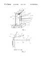
- FIG. 1illustrates a multiple window barcode reader suitable for both fixed and handheld operation
- FIG. 2illustrates a rotating facet wheel scan engine and two sets of scan pattern generating optics
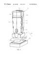
- FIG. 3is a front left side perspective view of a bimodal scanner positioned in a base unit
- FIG. 4is a rear right side perspective view of the scanner and base unit of FIG. 3;
- FIG. 5is an exploded view of the scanner and base unit of FIG. 3 showing the scanner removed from the base unit;
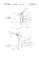
- FIG. 6is a front right side perspective view of an alternate bimodal with the second window in a top-forward position
- FIG. 7is a rear right side perspective view of another alternate bimodal scanner with the second window in a top rearward position
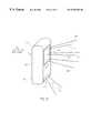
- FIG. 8is a front right side perspective view of another alternate bimodal scanner with the second window in a bottom-forward position
- FIG. 9is a rear right side perspective view of another alternate bimodal scanner with the second window in a bottom-rearward position
- FIG. 10is front right side perspective view of another alternate bimodal scanner with the second window in an inclined bottom section;
- FIG. 11illustrates a preferred scanning wheel configuration for providing an aiming beam
- FIG. 12is a schematic of a preferred scan engine configuration
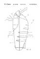
- FIG. 13is a front right side perspective view of a preferred ergonomic bimodal scanner
- FIG. 14is a left side elevation view of the scanner of FIG. 13;
- FIG. 15is an exploded perspective view of a base unit for the scanner of FIGS. 13-14;
- FIG. 16is a top plan view of a scan engine configuration of the scanner of FIGS. 13-14;
- FIG. 17is a left side elevation view of the scan engine of FIG. 16;
- FIG. 18is a diagram of the scan pattern produced by the scan engine of FIGS. 16-17;
- FIG. 19is a front right side perspective view of another bimodal scanner
- FIG. 20is a left side elevation view of the scanner of FIG. 19.
- FIG. 21is a diagrammatic view of a bimodal scanner which employs an imaging array.
- FIGS. 1-2illustrate a preferred embodiment of a multiple-mode data reading device, in this embodiment a bar code scanner 100 .
- the barcode scanner 100includes a top portion 102 and a bottom portion 101 .
- the scanner 100rests on a base unit 105 .
- a first scan window 104is shown on the front side 103 of the barcode scanner 100 through which a first scan pattern 106 is projected into a first scan volume C in front of the first scan window 104 .
- a second scan window 108is positioned on the top portion 102 of the barcode scanner 100 through which a second scan pattern 110 is projected into a second scan volume D in front of the second scan window 108 .
- the barcode scanner 100is placed in base unit 105 which supports the scanner for operation in the fixed mode.
- the scan pattern 106is optimized for fixed scanning within the scan volume C in front of scan window 104 .
- the fixed mode scan pattern 106preferably comprises a multi-dimensional or complex scan pattern, such as an asterisk or horse collar pattern) with a relatively large angular field of view suitable for fixed scanning applications.
- the scan pattern 106is preferably sufficiently dense so as to successfully read bar codes oriented in various orientations on objects passed through or placed within the scan volume in front of the scan window 104 .
- the operatormay lift barcode scanner 100 from the base unit 105 .
- the scan pattern 110 produced from scan lines passing through the second window 108is optimized for portable operation.
- the operatoraims the barcode scanner 100 to orient the place the scan pattern across the barcode.
- the portable mode scan pattern 110preferably comprises a pattern of one or a few scan lines (e.g. two or three parallel or slightly overlapping scan lines) with a longer depth of field and smaller angular field of view relative to fixed mode scan pattern 106 .
- the handheld mode scan pattern 110permits the user to aim the scan pattern onto a particular bar code, such as one bar code out of several located on an object, reading only a single bar code as desired.
- scan windows 104 and 108may be varied considerably in keeping with desired multi-modal operational characteristics set forth herein.
- Alternative embodiments of barcode scanner 100may have scan window 108 located on any of the sides of the unit, or even on the bottom of the unit. Ergonomic considerations specific to a particular device in its particular environment will determine the optimum relative placement of the scan windows 104 and 108 on the scanner 100 .
- FIG. 2illustrates one embodiment of a scan engine and optics for generating the scan patterns 106 and 110 using a moving spot generated from a laser beam.
- a laser diode 215generates a laser beam 216 which is focused by focusing optics 218 to form a reading beam 202 having the desired focal properties.
- the reading beam 202is directed onto a rotating facet wheel 200 which includes at least two sets of mirror facets. The mirror facets are set at two or more different angles.
- the first mirror facet set(having one or more facets) is aligned to direct the reading beam 202 onto steering mirror 204 , which in turn directs the reading beam 202 to the first scan pattern generating optics 206 , which may be comprised of for example a plurality of pattern mirrors, thereby generating first scan pattern 106 comprised of one or more scan lines.
- Scan pattern generating optics(diagrammatically designated by element numeral 206 ) may encompass the steering mirror 204 .
- a second mirror facet set (having one or more facets) of the facet wheel 200is aligned so that the reading beam 202 is directed to miss the steering mirror 204 and instead hit the second scan pattern generating optics (diagrammatically designated by element numeral 210 and comprised of a plurality of pattern mirrors for example), thereby generating the second scan pattern 110 .
- Each of the scan patterns 106 and 110may be optimized independently for fixed or portable operation as required, since the optics 206 and 210 preferably are completely separate and distinct. Either or both of the scan pattern generating optics 206 and 210 may include additional focusing optics to modify the depth of field, the focal distance, or the angular field of view of the scan patterns 106 and 110 , respectively.
- the focusing optics 218may include focusing capability, such as disclosed in Rudeen U.S. Pat. No. 5,479,011 herein incorporated by reference, for focusing the reading beam at different distances depending upon the mode of operation or depending upon which window 108 , 104 the beam is passing.
- the facets of the facet wheel 200may include focusing capability to provide selective focusing for different modes of operation.
- U.S. Pat. No. 4,560,862herein incorporated by reference, discloses using a rotating polygon having mirrors with different curvature on different facets thereof which provides scanning in different focal planes.
- the scanning wheel 200may produce a single scan line through the top window 108 optimized for handheld scanning operation.
- the pattern mirrors 210may comprise a single fold mirror or may even be omitted.
- the facet wheel 200may be oriented to direct a scan line from one or more facets directly out the window 108 .
- the scan line(s) 110 directed out of window 108may be optimized for handheld scanning operation relative to depth of field and distance for focus.
- the steering mirror 204may be omitted with one mirror facet (or multiple mirror facets) directing a scanning beams across pattern mirrors 206 and for producing scan lines 106 out window 104 .
- the scan line(s) directed out of window 104may be optimized for fixed mode scanning operation relative scan pattern geometry and density as well as to depth of field and focal distance.
- both scan patterns 106 , 110are present in either operational mode. It is noted, that since there is only one reading beam 202 (which as a moving spot produces the scan lines) , the scans are not actually simultaneous but are sequential. This means that one scan line produced by a mirror facet may pass through the first window 104 and then a scan line produced by the next mirror facet in sequence passes through the second window 108 . Because the facet wheel 200 rotates at a relatively high rate (typically in excess of about 2000 rpm) , the scan patterns 106 , 110 out of both windows 104 , 108 , are functionally operational though not technically simultaneous.
- the scanner 100may be provided with multiple reading beams such that the two scan patterns 106 , 110 are actually produced simultaneously.
- multiple scan pattern generationis disclosed in U.S. Pat. No. 5,475,207 to Bobba et al. herein incorporated by reference.
- the multiple reading beamsmay be formed by, for example, multiple laser diodes or a single laser diode and a beam splitter. Two separate beams may then be directed onto the facet wheel enabling two scanning beams to be generated simultaneously. If desired, the separate beams may be directed simultaneously out of separate windows.
- a mechanismmay be provided to selectively move the steering mirror 204 into or out of the path of illumination beam 202 as required.
- a mechanismis disclosed in U.S. Pat. No. 5,128,520 which is herein incorporated by reference. Only when the mirror 204 is moved into the path of the reading beam 202 are the scanning beams of the first scan pattern passed to the optics 206 , thereby generating first scan pattern 106 .
- a movable mirrormay be positioned to enable the second scan pattern 110 only when the mirror is moved into the path of the reading beam 202 .
- micro mirrorsmay alternately be used for providing the function of the movable mirror.
- Micro mirrorssuch as those used in projection televisions, move by solid state means, which may be advantageous.
- the scanneris provided with mechanically or electro-optically operated shuttering of one or both of the scan patterns 106 and 110 .
- a rotating shuttermay be placed between steering mirror 204 and rotating facet wheel 200 blocking off reading beam from reaching steering mirror 204 except when desired, such as upon selective actuation of switch 120 .
- Such a shutter mechanismis disclosed in U.S. Pat. No. 5,475,207 incorporated by reference.
- Beam selectionmay also be controlled via LCD modules providing an electronic method to redirect a polarized beam, such as the reading beam from a laser diode.
- a liquid crystal module and a polarizing mirrorare used to redirect or not affect a beam, depending on the state of the liquid crystal module. This may be useful to change scan patterns in different modes of operation, or to produce an aiming beam in handheld mode.
- An electro-optical shuttermay comprise a liquid crystal module (LCM) and a polarizing mirror in a beam path to redirect a reading beam to generate one scan pattern or the other, depending upon the mode of operation.
- LCDliquid crystal module
- polarizing mirrorin a beam path to redirect a reading beam to generate one scan pattern or the other, depending upon the mode of operation.
- An electro-optic shutter of this sortmay also be used to redirect a beam to serve as an aiming beam.
- a scan pattern suitable for fixed mode operationmay be produced by two or more sources.
- a scan pattern for handheld usemay not need the high density of scan lines generated in such a pattern, so one of the sources may be redirected to form an aiming beam.
- the beamsmay be controlled via acousto-optic elements.
- the scan windowsthemselves may comprise electro-chromatic materials or LCDs whereby scan lines could be selectively blocked from exiting (or permitted to exit) a selective one of the windows.
- the window 104may be electronically closed off thereby preventing scan lines from exiting that window. All the scan lines 106 , 110 could be continually generated, but during portable mode operation for example, only scan lines 110 could exit the scanner 100 because only window 108 would be rendered light transmissive.
- a particular operational modeis selected by selectively turning the illumination source 215 on and off as the reading beam 202 is directed onto the facet wheel 200 such that the illumination source is only on when the reading beam 202 hits a selected one or more facets on the facet wheel 200 .
- the facet wheel 200may generate a selective one of scan patterns 106 , 110 .
- the scanner 100may be equipped with a motion sensor 230 which senses that the unit has been picked up by the operator. When the sensor 230 detects motion, the scanner is switched to the handheld mode of operation with the first scan pattern 110 being projected through the scan window 108 . When the scanner 100 is returned to the base unit 105 , and the sensor 230 senses that the scanner is no longer in motion, the scanner 100 is then switched to the fixed mode of operation for scanning with the second scan pattern 106 being projected into the second scan volume in front of the scan window 104 .
- the portable scan pattern 110would not be usable since it would be obstructed by the base unit 105 .
- the second scan pattern 110could nonetheless be deactivated while the scanner 100 is in the base unit 105 .
- the scanner 100may be provided with a contact switch which activates the second scanning mode when the scanner is removed from the base unit 105 .
- the handheld modeis actuated by a manual actuator 120 on the scanner 100 itself.
- the actuator 120may require an intentional manipulation by the operator, for example, the actuator may include a slide switch or a trigger which the operator must manually actuate.
- the actuatormay include an automatic actuator, such as a sensor, which actuates the handheld operation mode upon grasping of the scanner housing.
- the switch 120may comprise a sensor which senses the operator's hand contacting the scanner housing, switching the scanner 100 to handheld mode.
- the scannermay include a timer for controlling the duration that the scanner switches between modes. For example, actuation of the switch 120 could switch the scanner 100 from the fixed mode to the portable mode, even though the scanner 100 remains in the base unit 105 , for a given period such as 30 seconds. Upon timing out the scanner 100 then returns to fixed mode.
- the barcode scanner 100may include an extra mirror or hood 130 external to the barcode scanner 100 positioned to reflect the scan pattern 110 into the scan volume in front of scan window 104 when barcode scanner 100 is used in fixed mode.
- the mirror 130may be attached to the base unit 105 as shown in FIG. 1 or may alternately may be mounted to the scanner 100 itself for example in a removable, pivoting or retractable form.
- the illumination source intensitymay be changed depending on mode of operation in use.
- itmay be desired to increase the intensity to accommodate extended depth of field and/or to make the scan pattern 110 more visible for aiming.
- the scan speedmay also be altered depending on the mode of operation, with slower scan speeds generally being more desirable for portable operation.
- Additional illumination sourcesmay be added to act as pointer beams which are particularly desirable while in the portable or handheld mode. Activation and deactivation of these options may be accomplished manually or automatically, as described the above.
- These and other mode optionsmay be preset at manufacture, selectively activated by setting the option by the vendor or a programming technician, programmed by the operator as described in U.S. Pat. Nos. 4,861,972 or 4,866,257, or set via use of a connection cable as in U.S. Pat. No. 5,330,370, these patents also being incorporated by reference.
- Aiming beams to assist the operator in aiming the scannerare particular useful in the portable mode where the scan pattern is preferable a single scan line and often has an extended scan range. Possible methods which may be employed for generating aiming beams are described in U.S. Pat. Nos. 4,603,262, 5,296,689 and 5,146,463, herein incorporated by reference.
- FIGS. 11-12One preferred aiming beam generation system is illustrated in FIGS. 11-12 wherein the rotating facet wheel 250 includes four scanning facets 252 , 254 , 256 , 258 with one or more corners 260 of the facet wheel 250 being cutout to form two small facets 262 , 264 arranged perpendicularly to one another.
- the reading beam 251 impinging on the facets 252 , 254 , 256 , 258produces scanning beams as the beams are directed across the pattern mirrors as described above with respect to FIGS. 1 and 2.
- the beamtends to more slowly scan, that is the outgoing beam 261 is directed along parallel paths for the time it takes the reading beam 251 to traverse both corner facets 262 , 264 .
- the beam reflected by the corner facets 262 , 264tends to generate a higher brightness forming a more visible line segment aiming beam.
- the mirror facet 508is angled to produce the portable mode scan line 110 passing through the upper window 108 .
- Corners 260 , 270 on opposite sides of the facet 252include corner facets 262 , 264 and 271 , 272 .
- Each of the corner mirror pairs 262 & 264 and 271 & 272each produces an aiming line segment (per rotation), for example one aiming line segment formed on each end of the scan line 110 produced by facet 508 .
- the aiming line segmentsmay be formed or allowed to exit only in conjunction with the scanning beam 110 in keeping with the various embodiments described herein.
- facet wheel 250may contain one or more corner cubes 260 , 270 , 280 .
- a corner cubemay be used to create an aiming beam for use in handheld mode.
- a corner cubeincludes of two facet mirrors whose intersection forms a line which is parallel to the facet wheel axis of rotation 290 . Referring to FIG. 12, during a portion of a revolution in which a scanning beam 251 strikes corner cube 260 , the exiting beam 261 is parallel thereto.
- the exiting beam 261will also be in the incident scanning beam plane. If incident scanning beam 251 is not in a plane substantially perpendicular to the planes of corner cube mirror facets 262 , 264 but at an angle of incidence, then exiting beam 261 will have a substantially equal angle of reflection. Thus, the reading beam appears to be reflected back substantially along the incoming path.
- the reading beam 251 generated by a light source such as a laser diode 255is directed by a fold mirror 273 onto the facet wheel 250 striking either of the facets of the corner cube 260 which may be angled with respect to the facet wheel axis 290 so that the reflected beam 261 is directed at mirror 268 , and then is reflected out scan window 108 , forming a substantially brighter line segment or aiming beam.
- mirror 268may be eliminated.
- Mirror 204alternately directs the reading beam 251 for generating the first scan pattern 106 comprised of one or more scan lines.
- the base unit 105may contain a power supply, signal processing, decoding, and/or control electronics and may be connected to the barcode scanner 100 by a hardwired connection or by a wireless connection. Wireless communications may be accomplished by suitable infrared or RF transmission.
- the scanner 100will generally be battery powered in the handheld mode; the battery may be charged while in place on the base unit in similar fashion as a cordless telephone.
- connection for both communication and powermay be provided through mating electrical contacts in the base 105 and the scanner 100 .
- the power supply, signal processing, decoding, and/or control electronicsmay be located on board the barcode scanner 100 with the base unit 105 simply providing mechanical support for the barcode scanner 100 .
- the base unit 105may be eliminated altogether and the barcode scanner 100 may be a free standing unit, with either a hardwired or wireless connection to a terminal or host computer.
- the wireless communicationmay be accomplished by suitable infrared or RF transmission, for example.
- the barcode scanner 100either with or without base unit 105 , may also be mounted, suspended, or placed in arbitrary locations and at various orientations.
- FIGS. 3-5illustrate a cordless scanner 300 resting in a base unit 325 .
- the scanner 300includes a scanner housing 301 which is generally rectangular in cross section with curved sides comprising plural indentations 312 to permit comfortable grasping of the unit.
- the scanner housing 302includes a top housing portion 301 b and a bottom housing portion 301 a .
- the scanner 300has two windows, one window for each of the operational modes.
- the front window 304faces sidewardly outward into a scan volume beside the scanner 300 , the scan volume being defined as beside the scanner when the scanner 300 is placed in its base unit 325 .
- the first scan window 304is generally located in the top portion 301 b of the scanner housing 301 .
- the second window 308is located on a top face of the scanner 300 and is used for the handheld operational mode.
- the scanner 300may be readily grasped and removed from the base unit 325 .
- the unit 300may be switched to handheld operation mode by any one of a number of mechanisms as described above.
- the scanner 300is shown having a trigger switch 320 which is readily actuated by the operator merely by grasping the housing 302 .
- the scanner 300may have a cable connection for providing power and communication link or the unit may be battery powered and cordless with communications accomplished by infrared or RF transmission, for example.
- the base unit 325includes a cup portion 330 into which the scanner 300 may be inserted, a main base section 326 and a swivel section 328 which would allow for some orientation of the scanner 300 during the fixed mode of operation to modify the orientation of the first window 304 and thereby adjust the location of the scan volume.
- FIG. 6illustrates an alternative scanner 350 having a housing 352 with a top portion 351 and a bottom portion 353 .
- the scanner 350has a first window 354 for the fixed mode generating a generally denser scan pattern 356 passing into the scan volume C in front of the front face of the scanner 350 .
- a second window 358is positioned on the top portion 351 of the scanner inclined between front and top surfaces of the scanner 350 whereby the scan pattern 360 is directed generally forward and upward from the scanner 350 .
- FIG. 7is a perspective view of another scanner 370 in which the second window 378 for the handheld mode is located on a reartop side of the housing 372 .
- the scan pattern 380 generated through the second window 378is directed generally rearwardly at a slightly upward angle.
- the first window 374is located on the front face (not visible but shown by the dotted lines) through which the generally more dense scan pattern 376 passes into the scan volume C for the fixed mode of operation.
- FIG. 8illustrates yet another alternate embodiment for a scanner 400 having a first window 404 on the front face thereof through which scan lines 406 generate a scan pattern into the scan volume C for the fixed mode.
- Housing 402includes a bottom portion 401 on which the second window 408 is located.
- the second window 408is positioned between the bottom surface and the front face which would direct a scan pattern 410 generally downwardly and forwardly from the second window 408 . Since the scanner 400 would normally be placed in a holder during the fixed mode, the operator may more readily grasp the top portion 403 of the scanner in locating the second window 408 on the bottom facilitates convenient use of the scanning beams 410 for the handheld mode of operation.
- the second window 408may be covered thereby blocking scan lines from exiting during the fixed mode.
- FIG. 9illustrates yet another scanner 420 which is similar to the scanner 400 of FIG. 8 except the second window 428 is located more toward the rear side of the bottom portion 421 of the scanner housing 420 .
- the scan pattern 430 generated when passing through the second window 428is directed downwardly and rearwardly from the scanner 420 .
- the front or first window 404(not visible but shown by dashed lines) is located on the front face of the scanner 420 . Scanning beams 426 pass through the first window 404 and into the scan volume C in the fixed mode of operation.
- FIG. 10illustrates yet another alternate embodiment of a scanner 440 having a first window 444 on the front face of the scanner housing 442 through which a scan pattern 446 passes into the scan volume C during the fixed mode of operation.
- the second window 448is located in a bottom portion 441 of the scanner housing 442 in an incline section 443 of the bottom housing portion 441 .
- This incline section 443extends past the plane of the front face of the scanner (the first window being in the plane of the front face) which allows positioning of the second window 448 such that the scan beams 450 emanating therefrom for use in the handheld mode also pass through the scan volume C.
- the scan lines 450 passing through the second window 448may provide additional scanning coverage in the front scan volume C.
- the scan pattern 446may be discontinued if desired.
- FIGS. 13-15illustrate a preferred embodiment of a multiple mode barcode scanner 500 .
- the barcode scanner 500includes a top portion 502 , a bottom portion 504 , a front portion 510 and a back portion 511 .
- the scanner 500When operating in fixed mode, the scanner 500 preferably rests in a base unit 506 which is illustrated in the FIG. 15 exploded view.
- a first scan window 508is located on front portion 510 , through which a first scan pattern 512 is projected into a first scan volume C in front of first scan window 508 .
- a second scan window 514is located on top portion 502 through which a second scan pattern 516 is projected into a second scan volume D in front of second scan window 514 .
- the scan pattern 512is optimized for fixed scanning within the scan volume C in front of scan window 508 .
- the scan pattern 512preferably comprises a multidimensional scan pattern with a relatively large angular field of view suitable for fixed scanning applications. Bar coded objects to be read are passed through the scan volume C (i.e. the sweep mode) or placed within the scan volume C (i.e. the presentation mode).
- the base unit 506contains a swivel 520 which may allow for orientation of the scanner 500 when mounted in base unit 505 , which may be particularly useful during the fixed mode of operation, in order to adjust the orientation of first window 508 and thereby adjust the location of scan volume C.
- the scanner 500preferably has a low center of gravity providing stability even when tilted at a wide range of angles when resting in the base unit 506 , which may be facilitated by placing heavier internal components and/or weights in the bottom portion 504 .
- the scan pattern 516When the handheld mode of operation is desired, an operator may lift the barcode scanner 500 from base unit 506 .
- the scan pattern 516which is optimized for handheld operation, may be directed or aimed toward a barcode to be read thereby putting said bar code within scan volume D in front of scan window 514 .
- An aiming beammay be provided to facilitate handheld use.
- the scan pattern 516preferably comprises a pattern of at least one scan line with a longer depth of field and a smaller angular field of view relative to scan pattern 512 .
- the scanner 500preferably may have substantially symmetrical curvelinear surfaces on front and back portions 510 and 511 whereby a horizontal cross-section A—A in FIG. 14 renders a substantial ellipsoidal shape, thereby providing a convex shape to fit the concave shape created by an operator opening their hand/palm yet curving the ends of their fingers and thumb.
- back portion 511and in part front portion 510 , includes a plurality of grip-strips 524 , which are preferably co-molded to permit comfortable, firm, and safe ergonomic grasping of the unit. Co-molded grip-strips 524 may facilitate manufacturing and reduce the cost of scanner housing manufacturing.
- the bottom portion 504preferably is tapered, allowing scanner 500 to be easily placed into and removed from concave portion 526 of the base unit 506 .
- the scanner 500is depicted with a triggering means shown as a manually-actuated switch 528 , which may be used to: activate an aiming beam; activate the scan pattern 516 ; enable decoding during the time scan pattern 516 is generated; disable the scan pattern 512 ; and/or disable decoding during the time scan pattern 512 is generated.
- a triggering meansshown as a manually-actuated switch 528 , which may be used to: activate an aiming beam; activate the scan pattern 516 ; enable decoding during the time scan pattern 516 is generated; disable the scan pattern 512 ; and/or disable decoding during the time scan pattern 512 is generated.
- both scan patterns 512 and 516are always enabled, and the switch 528 is used to activate an aiming beam and only enable decoding during the period in which scan pattern 516 is generated.
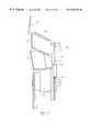
- FIGS. 16-17A preferred embodiment scan engine for producing fixed and handheld patterns sequentially during each rotation of the mirrored polygon is shown in FIGS. 16-17.
- the scan engine mirror basketcontains a pair of split pattern mirrors which produce substantially parallel scan lines that cross at different distances from the scan window and exit the scan window at different angles. This provides good performance in both sweep and presentation modes.
- the scan engine 560is housed within the top portion 502 of barcode scanner 500 including optical elements for generating scan patterns 512 and 516 from a moving spot generated from a laser scanning beam 556 generated by visible laser diode module (VLDM) 554 which is direct to rotating facet wheel 558 .
- FIG. 16is a front view of scan engine 560 as if looking through scan window 508 of scanner 500
- FIG. 17is a side view thereof.
- a laser diode 550generates a laser beam which is focused by focusing optics within VLDM 554 to form scanning beam 556 having the desired optical properties for barcode scanning which are well known in the art.
- Scanning beam 556preferably is directed to a small insert mirror 561 in a collection mirror 562 toward facet wheel 558 .
- the facet wheel 558preferably includes two or more mirror facets set at two or more different angles. As facet wheel 558 rotates, scanning beam 556 reflected from any one facet mirror may be sequentially swept across one or more of the pattern mirrors 564 , 565 , 566 , 580 , 581 , 582 and 583 .
- a scan lineis reflected through scan window 508 into scan volume C.
- One or more of the facet mirrorsmay be set at an angle so that for at least a portion of a single revolution of facet wheel 558 the reflected beam misses pattern mirrors 564 , 565 , 566 , 580 , 581 , 582 and 583 , which reflect the beam through scan window 508 , allowing scanning beam 556 to be directed through scan window 514 .
- pattern mirror 566is shortened, so the beam reflected from one or more of the wheel facets preferably may reflect off of mirror 568 and be directed to the alternate scan window 514 .
- the scan pattern which is projected through scan window 508may have characteristics which increase first pass read rates for two types of fixed scanner use; presentation mode (wherein a barcoded object is brought toward the scanner in a path substantially perpendicular to the scanner window) and sweep mode (wherein a barcoded object is moved past the scanner window in a path substantially parallel to the scanner window).
- presentation modewherein a barcoded object is brought toward the scanner in a path substantially perpendicular to the scanner window
- sweep modewherein a barcoded object is moved past the scanner window in a path substantially parallel to the scanner window.
- the patterncomprises a number of lines at a wide range of orientations (their angle and location) which are projected at a small angle from perpendicular to scan window 508 , crossing relatively far from scan window 508 , which increases first pass read rates when objects with barcodes thereon are presented to scan window 508 , preferably mounted in base unit 506 .
- Vertical scan linesare in two groups, the lines 570 a , 570 b produced by inner pattern mirrors 580 , 581 respectively and the lines 572 , 572 b are produced by outer pattern mirrors 582 and 583 respectively.
- the lines 572are projected at a relatively large angle from perpendicular to the scan window 508 , crossing relatively close to the scan window 508 , which increases first pass read rate when objects with barcodes thereon are swept pass scan window 508 .
- the split pattern mirror pair 580 , 582 and pair 581 , 583are producing substantially vertical scan lines 570 a , 570 b and 572 a , 572 b respectively and mirror 566 projects scan lines 578 at different angles in a substantially horizontal plane, which may not increase the number of scan lines but may increase the number of orientations (angle and/or location) of the scan lines.
- the intermediate mirror 564produces four angled scan lines 573 , 574 (one for each primary facet of the wheel 558 ) while intermediate mirror 565 produces four angled scan lines 575 , 576 .
- Alternative embodimentsmay split different pattern mirrors and/or different sets of pattern mirrors.
- the scan generation methodwhich include two reading beams (for example two beams created by two VLDM's or a by single VLDM and a beam splitter), two collection mirrors, and two detectors.
- the arrangementis bilaterally symmetric.
- a laser beamemerges from a hole in a collection mirror, strikes a rotating polygon facet wheel, reflects off of a pattern mirror, and then through a scan window for fixed mode use.
- the facet wheeldirects the beam in such a way that it does not strike a pattern mirror, and instead the beam exits directly through a different scan window for handheld use.
- FIGS. 16-17Numerous alternative embodiments of the scan engine and optics shown in FIGS. 16-17 may be employed.
- two or more laser sourcesmay be employed. Since a return path of light reflected or back scattered from a barcode may be along the outgoing path of the reading beam, although widened considerably, it may be useful to employ a detector for each source.
- the scannermay be equipped with a mechanism for producing a signal which is synchronized with the facet wheel rotation.
- the signalin conjunction with timers, may be used to control various scanner functions which relate to the facet wheel position such that the scanner functions are optimal for either handheld or fixed scanning. These functions may include scan pattern generation, decoding, and aiming beam generation.
- the synchronization signalmay be used to disable an aiming beam produced by a corner cube on the facet wheel unless a button is actuated.
- the synchronization signalmay also be also used to disable decoding when a scan line emerges from the scan window for handheld use unless the button is actuated.
- scanner functionswhich relate to facet wheel rotation/location for which it may be useful to control according to whether the scanner is in fixed or handheld operation. These functions may include scan pattern generation, aiming beam function, and decoding.
- a signal which is synchronized to the facet wheel rotationherein referred to as an electrical glitch, may be generated. This electrical glitch may be used to control timers which enable and disable various functions during a certain portion of a revolution.
- generation of an aiming beamwhich is preferable in handheld operation, by a corner cube may be disabled unless a switch or trigger is actuated. This disabling is accomplished by turning off the laser diode 550 whenever the scanning beam 556 would strike a corner cube, which happens during a fixed portion of each revolution of facet wheel 558 .
- the electrical glitchmay be generated in many ways.
- a number of these methodsuse a laser diode already present for scan pattern generation, and may use a photo detector already present for data capture or alternatively a dedicated photo detector.
- a preferred embodimentuses a dedicated detector, which may capture an optical signal, herein referred to as an optical glitch, by directing the reading beam toward the detector only when the facet wheel is in a particular orientation, so that one electrical pulse is generated by the detector for each facet wheel revolution.
- the beamis directed toward the dedicated detector by an optical glitch mirror, wherein the scanning beam will reflect onto the dedicated detector once every revolution.
- the optical glitch mirrormay direct the beam directly toward the dedicated detector, or it may be designed to direct the beam toward any of the mirrors already present which are designed to reflect the beam to the dedicated detector or the existing detector used to detect collected light from a bar code to be read.
- one or more additional mirrorsmay be employed separately or in conjunction with pattern mirrors already present, or functional equivalents, allowing the detector to be placed in any convenient location within the scanner.
- reflective tape or a mirror insertmay be placed on any portion of the facet wheel which the scanning beam may strike, the reflective tape or mirror insert may then direct the “glitch” beam toward a detector in a path that may be direct or may involve one or more mirrors or their functional equivalent.
- An alternative to a -mirrormay involve a scan window, especially if the beam is perpendicular to the window.
- a beam splittermay be used to direct the glitch beam to a detector, wherein the remaining beam may be used, for example, as the pointer.
- the optical glitch mirrormay not be on the facet wheel, but at any position within the scanner toward which the scanning beam is reflected by the facet wheel once per revolution, such as corner cube 590 . However, this may be located on a pattern mirror, between pattern mirrors, or where a pattern mirror directs the beam. At any one of these locations, the detector may be placed, or a mirror or a functional equivalent may be placed which directs the glitch beam, either directly or after one or more reflections, to a detector.
- Another alternative to the optical glitch mirror on the facet wheelis simply a hole through the facet wheel, through which the reading beam may proceed toward the detector, either directly or after one or more reflections.
- the electrical glitchmay be generated by directing the glitch beam on the detector already present for the purpose of bar code data capture. So that the optical glitch is not confused with bar code data, it may be brighter than any other signal that may be expected during data capture. Any of the methods described supra for use with a dedicated detector may be employed, provided that the path from the optical glitch mirror equivalent leads back to the bar code data detector and provides an optical signal distinguishable from bar code data.
- a light source other than the laser diode which generates the scanning beammay employ a light source other than the laser diode which generates the scanning beam.
- Possible sourcesinclude a laser diode or a LED. This second source may be employed with a dedicated detector or with the data detector, in any of the embodiments described above.
- the data detectoris used to detect the optical glitch, a stray optical signal may inadvertently be interpreted as the optical glitch. To avoid this problem, it may be useful to capture the optical glitch only once during a startup phase and count motor revolutions to remain synchronized thereafter.
- the facet wheelis rotated by a DC brushless motor which produces a Hall output pulse six times for each motor revolution.
- a divide by six countermay generate a single pulse for each motor revolution.
- This pulsemay be synchronized once to a known facet wheel position by an optical glitch method described supra, after which the Hall pulses may accurately maintain synchronization to facet wheel motion.
- This embodimentmay require accurate orientation of the facet wheel on the motor shaft to ensure the Hall pulses coincide with a known facet wheel orientation.
- phase locked loop multiplierto produce 6N pulses per revolution from the six Hall pulses, and then to employ a divide by 6N counter to produce one pulse per revolution. This may allow the electrical glitch to be accurately synchronized to the facet wheel position within 1 ⁇ 6N of a revolution.
- a piece of material or a circuit rotating with the facet wheelmay generate a signal in a fixed circuit as the rotating material or circuit passes the fixed circuit.
- a magnet or a circuit with a current which produces a magnetic fieldmay be on the facet wheel, and a circuit which is sensitive to changes in magnetic field, such as a Hall sensor, may produce the electrical glitch as the magnet or circuit on the facet wheel passes the fixed circuit.
- a piece of material with high magnetic permeabilitymay be on the facet wheel, and a circuit sensitive to its proximity may produce the electrical glitch.
- a circuit which is sensitive to changes in electric fieldmay produce an electrical glitch as a piece of charged material, such as an electret, passes the fixed circuit.
- a piece of material with high permissivitymay be sensed capacitively, or a capacitor could be split with one portion moving with the facet wheel so that the electrical glitch is produced as it passes the fixed portion of the capacitor.
- the sensing circuitmay be rotated with the facet wheel and the material or other circuit may be fixed.
- a timing meansmay be used to produce signals to control various scanner functions.
- the timing meansmay consist of one or more one shot timers or a microprocessor which may generate timing signals.
- the timing means and motormay be synchronized during portions of a revolution of the facet wheel by using pulses from one to control the other.
- the timer signalsmay be used to control any function which relates to the facet wheel rotation and which may be different in fixed mode or handheld mode. For example, the scan pattern is different in the two modes, and the read rate when the scanner is in one mode of operation may not benefit at all if the other scan pattern is active (e.g. in the preferred embodiment, the read rate would not improve if the fixed scan pattern was active when the scanner was in the handheld mode of operation).
- a timing signalmay be used to turn the scanning beam light source, preferably a visible laser diode, off whenever the facet wheel is aligned to produce a scan line which is not needed in the current mode of operation. This may reduce power consumption, decrease inadvertent reads, extend the life of the light source, reduce servicing, and reduce the likelihood of laser related injuries.
- Signal processing and or decodingmay be disabled whenever the facet wheel is aligned to produce a scan line which is not needed in one mode of operation. This too will reduce power consumption, decrease inadvertent reads, reduce servicing, and inhibit inadvertent reads.
- An aiming beammay also be controlled by timing signals, as in a preferred embodiment wherein, during fixed mode use, the laser is turned off whenever the scanning beam would strike a corner cube and produce an aiming beam.
- shutting the light source off during a portion of a facet mirror rotationif necessary.
- micro mirrors or acousto-optic meanscould be used to redirect the scanning beam to achieve performance discussed above.
- FIGS. 19-20illustrate yet another scanner 700 comprising of a spherical head portion 712 , with one or more windows 712 , 714 .
- the head portion 710rests on a pedestal 720 from which the spherical head portion 710 may be removed for handheld use.
- the scanner 700may rest on the pedestal 720 in nearly any orientation. Any of the internals of a scanner described herein may be housed in such an embodiment.
- the pedestal 700may house much of the electronics.
- the head portion 710may contain the scan engine for generating scan patterns for both fixed and handheld use, as well as a wireless connection to the pedestal 720 .
- the head portion 710may also include indentations 716 on its sides to readily enable grasping.
- the head portion 710may rest on the pedestal 720 in nearly any orientation, and may be secured in a particular orientation by hook and loop fabric or other suitable mechanical or magnetically releasable retention mechanism.
- the pedestal portion 720may include or be supported by a base portion 722 with electrical connection to the host or terminal provided by a suitable cable 724 or wireless connection.
- FIG. 21illustrates another alternative embodiment, a multi-window data capture device 800 which employs an imaging array 810 .
- the optics 808 which create an image on the array 800 with light from an object in front of window 806is optimized for fixed mode operation, providing a wide field of view.
- the optics 804 which create an image on the array 800 with light from an object in front of window 802is optimized for handheld mode of operation, providing a large depth of field. This may be accomplished by using a Sheimpflug arrangement, such as described in U.S. Pat. No. 4,978,860, which is herein incorporated by reference.
- the Sheimpflug arrangementallows the aperture of lens 804 to be as large as desired, to maximize resolution, without substantially affecting the depth of field, since the depth of field is provided primarily by the range of lens to imager distances available because the planes of the imager and the lens are not parallel.
- the relative configuration of windows 802 and 806may be changed by employing mirrors. This may allow many of the configurations described herein which employ a flying spot means to be used with the imaging array of FIG. 21 .
- An alternative embodimentmay enable or disable one or the other of the optical paths, depending on the mode of operation. This may be accomplished with a mechanical shutter or with a LCD shutter as described herein. Rather than a shutter and a lens for each mode of operation, a single lens may be used and simply moved from the position of lens 808 to the position of lens 804 . This would effectively disable one mode when the other mode is operational. Illumination may be provided by the data capture device, which may be especially useful for handheld operation.
- a sheet of light generated by a laseris used for illumination in a Sheimpflug arrangement, and this illumination may also function as an aiming beam.
- Other specific arrangements for imaging array mechanismare disclosed in allowed U.S. application Ser. No. 08/363,258, which is herein incorporated by reference.
Landscapes
- Physics & Mathematics (AREA)
- Engineering & Computer Science (AREA)
- Electromagnetism (AREA)
- Artificial Intelligence (AREA)
- Toxicology (AREA)
- General Health & Medical Sciences (AREA)
- Health & Medical Sciences (AREA)
- Computer Vision & Pattern Recognition (AREA)
- General Physics & Mathematics (AREA)
- Theoretical Computer Science (AREA)
- Mechanical Optical Scanning Systems (AREA)
- Image Input (AREA)
- Facsimile Scanning Arrangements (AREA)
Abstract
Description
Claims (27)
Priority Applications (9)
| Application Number | Priority Date | Filing Date | Title |
|---|---|---|---|
| US08/792,829US6575368B1 (en) | 1996-01-31 | 1997-01-30 | Multiple aperture data reader for multi-mode operation |
| DE19781569TDE19781569B4 (en) | 1996-01-31 | 1997-01-31 | Data reading device with a plurality of openings for a plurality of operating modes |
| JP09527927AJP2000515655A (en) | 1996-01-31 | 1997-01-31 | Data reader with multiple windows for multi-mode operation |
| GB9812325AGB2324634B (en) | 1996-01-31 | 1997-01-31 | Multiple aperture data reader for multi-mode operation |
| PCT/US1997/001818WO1997028512A1 (en) | 1996-01-31 | 1997-01-31 | Multiple aperture data reader for multi-mode operation |
| GB0006829AGB2345370B (en) | 1996-01-31 | 1997-01-31 | Data reader |
| US10/418,988US6719201B2 (en) | 1996-01-31 | 2003-04-18 | Multiple aperture data reader for multi-mode operation |
| US10/797,781US7051940B2 (en) | 1996-01-31 | 2004-03-09 | Data reader for multi-mode operation |
| US11/149,012US7243850B2 (en) | 1996-01-31 | 2005-06-08 | Data reader for multi-mode operation |
Applications Claiming Priority (2)
| Application Number | Priority Date | Filing Date | Title |
|---|---|---|---|
| US1093596P | 1996-01-31 | 1996-01-31 | |
| US08/792,829US6575368B1 (en) | 1996-01-31 | 1997-01-30 | Multiple aperture data reader for multi-mode operation |
Related Child Applications (1)
| Application Number | Title | Priority Date | Filing Date |
|---|---|---|---|
| US10/418,988ContinuationUS6719201B2 (en) | 1996-01-31 | 2003-04-18 | Multiple aperture data reader for multi-mode operation |
Publications (1)
| Publication Number | Publication Date |
|---|---|
| US6575368B1true US6575368B1 (en) | 2003-06-10 |
Family
ID=26681770
Family Applications (4)
| Application Number | Title | Priority Date | Filing Date |
|---|---|---|---|
| US08/792,829Expired - LifetimeUS6575368B1 (en) | 1996-01-31 | 1997-01-30 | Multiple aperture data reader for multi-mode operation |
| US10/418,988Expired - LifetimeUS6719201B2 (en) | 1996-01-31 | 2003-04-18 | Multiple aperture data reader for multi-mode operation |
| US10/797,781Expired - LifetimeUS7051940B2 (en) | 1996-01-31 | 2004-03-09 | Data reader for multi-mode operation |
| US11/149,012Expired - Fee RelatedUS7243850B2 (en) | 1996-01-31 | 2005-06-08 | Data reader for multi-mode operation |
Family Applications After (3)
| Application Number | Title | Priority Date | Filing Date |
|---|---|---|---|
| US10/418,988Expired - LifetimeUS6719201B2 (en) | 1996-01-31 | 2003-04-18 | Multiple aperture data reader for multi-mode operation |
| US10/797,781Expired - LifetimeUS7051940B2 (en) | 1996-01-31 | 2004-03-09 | Data reader for multi-mode operation |
| US11/149,012Expired - Fee RelatedUS7243850B2 (en) | 1996-01-31 | 2005-06-08 | Data reader for multi-mode operation |
Country Status (5)
| Country | Link |
|---|---|
| US (4) | US6575368B1 (en) |
| JP (1) | JP2000515655A (en) |
| DE (1) | DE19781569B4 (en) |
| GB (2) | GB2324634B (en) |
| WO (1) | WO1997028512A1 (en) |
Cited By (49)
| Publication number | Priority date | Publication date | Assignee | Title |
|---|---|---|---|---|
| US20020030108A1 (en)* | 1991-07-25 | 2002-03-14 | Paul Dvorkis | Two-dimensional optical code scanner with scanning pattern having region of greater apparent brightness for assisting alignment of scanning pattern |
| US20020060245A1 (en)* | 1991-07-25 | 2002-05-23 | Symbol Technologies, Inc., A Delaware Corporation | Optical scanner with segmented collection mirror |
| US20030001014A1 (en)* | 1995-07-20 | 2003-01-02 | Fujitsu Limited | Optical reader applicable to plurality of uses |
| US20030067681A1 (en)* | 2001-10-05 | 2003-04-10 | Claudio Mazzone | Optical reading apparatus |
| US20030085284A1 (en)* | 2000-02-28 | 2003-05-08 | Psc Scanning, Inc. | Multi-format bar code reader |
| US20030119494A1 (en)* | 2001-12-20 | 2003-06-26 | Seppo Alanara | Wireless terminal having a scanner for issuing an alert when within the range of a target wireless terminal |
| US20030178492A1 (en)* | 1996-01-31 | 2003-09-25 | Psc Scanning, Inc. | Multiple aperture data reader for multi-mode operation |
| US20040004125A1 (en)* | 1998-07-10 | 2004-01-08 | Welch Allyn Data Collection, Inc. | Method and apparatus for extending operating range of bar code scanner |
| US20040046114A1 (en)* | 1996-10-08 | 2004-03-11 | Psc Scanning, Inc. | Off-axis object detection system for a bar code scanner |
| US20050039052A1 (en)* | 2002-01-11 | 2005-02-17 | O'donnell James | Ease of use transaction terminal |
| US20050150959A1 (en)* | 2004-01-09 | 2005-07-14 | John Izzo | Optical reader |
| US20060081712A1 (en)* | 2004-10-18 | 2006-04-20 | Psc Scanning, Inc. | System and method of optical reading employing virtual scan lines |
| US20060113386A1 (en)* | 2004-12-01 | 2006-06-01 | Psc Scanning, Inc. | Illumination pulsing method for a data reader |
| US7059529B1 (en)* | 1998-09-14 | 2006-06-13 | Datalogic Spa | Device for reading a barcode |
| US20060180670A1 (en)* | 2004-12-01 | 2006-08-17 | Psc Scanning, Inc. | Triggering illumination for a data reader |
| US20060238550A1 (en)* | 2005-03-17 | 2006-10-26 | Symagery Microsystems Inc. | Hands-free data acquisition system |
| US20070170261A1 (en)* | 2006-01-20 | 2007-07-26 | Noriaki Shimura | Compact scan engine disposed within a scanner housing |
| US20080259428A1 (en)* | 2004-09-30 | 2008-10-23 | Zimdars David A | Optical Delay |
| US7451917B2 (en) | 2002-01-11 | 2008-11-18 | Hand Held Products, Inc. | Transaction terminal comprising imaging module |
| US7472825B2 (en) | 2002-01-11 | 2009-01-06 | Hand Held Products, Inc. | Transaction terminal |
| US7479946B2 (en) | 2002-01-11 | 2009-01-20 | Hand Held Products, Inc. | Ergonomically designed multifunctional transaction terminal |
| US7556203B2 (en) | 2005-06-27 | 2009-07-07 | Hand Held Products, Inc. | Method and system for linking a wireless hand held optical reader with a base unit or other wireless device |
| US20090294541A1 (en)* | 2007-12-21 | 2009-12-03 | Laurens Nunnink | Handheld Code Reader Having A Motion Sensor |
| US7686216B2 (en) | 2006-06-13 | 2010-03-30 | Hand Held Products, Inc. | Method and apparatus for uniquely associating a bar code reading terminal to a cash register in a retail store network |
| US20100133345A1 (en)* | 2008-12-02 | 2010-06-03 | Hand Held Products, Inc. | Indicia reading terminal having plurality of optical assemblies |
| US7748620B2 (en) | 2002-01-11 | 2010-07-06 | Hand Held Products, Inc. | Transaction terminal including imaging module |
| EP2208998A2 (en) | 2005-05-02 | 2010-07-21 | ANP Technologies, Inc. | Polymer conjugate enhanced bioassays |
| US20100193588A1 (en)* | 2009-02-04 | 2010-08-05 | Datalogic Scanning, Inc. | Systems and methods for selectively masking a scan volume of a data reader |
| US7770799B2 (en) | 2005-06-03 | 2010-08-10 | Hand Held Products, Inc. | Optical reader having reduced specular reflection read failures |
| US7780089B2 (en) | 2005-06-03 | 2010-08-24 | Hand Held Products, Inc. | Digital picture taking optical reader having hybrid monochrome and color image sensor array |
| EP2264191A1 (en) | 2003-11-21 | 2010-12-22 | ANP Technologies, Inc. | Asymmetrically branched polymer conjugates and microarray assays |
| US20110017828A1 (en)* | 2009-07-24 | 2011-01-27 | Jadak, Llc | Handheld optical imaging device and method |
| US7929498B2 (en) | 1995-06-30 | 2011-04-19 | Interdigital Technology Corporation | Adaptive forward power control and adaptive reverse power control for spread-spectrum communications |
| US8074887B2 (en) | 2002-06-04 | 2011-12-13 | Hand Held Products, Inc. | Optical reader having a plurality of imaging modules |
| US20120145791A1 (en)* | 2010-12-08 | 2012-06-14 | Ncr Corporation | Hybrid imaging optical code reader |
| US8336780B1 (en)* | 2010-06-15 | 2012-12-25 | Webscan, Inc. | Windowed housing with rotatable imaging device |
| US8517272B1 (en)* | 2012-04-25 | 2013-08-27 | Symbol Technologies, Inc. | Method to differentiate aiming from active decoding |
| US8720781B2 (en) | 2005-03-11 | 2014-05-13 | Hand Held Products, Inc. | Image reader having image sensor array |
| US8737363B2 (en) | 1995-06-30 | 2014-05-27 | Interdigital Technology Corporation | Code division multiple access (CDMA) communication system |
| US8733660B2 (en) | 2005-03-11 | 2014-05-27 | Hand Held Products, Inc. | Image reader comprising CMOS based image sensor array |
| USD724088S1 (en)* | 2014-07-16 | 2015-03-10 | Spx Corporation | Remote fare reader |
| USD735197S1 (en)* | 2014-03-26 | 2015-07-28 | Optoelectronics Co., Ltd. | Optical information reader |
| USD754662S1 (en)* | 2014-04-01 | 2016-04-26 | Datalogic Ip Tech S.R.L. | Coded information reader |
| US9411985B2 (en) | 2013-01-24 | 2016-08-09 | Cisco Technology Inc. | Passing hidden information using attack detectors |
| CN106778431A (en)* | 2017-03-07 | 2017-05-31 | 海宁市乔斯特新能源有限公司 | A kind of installation housing of wrist bar code recognizing apparatus |
| US10127422B1 (en) | 2007-12-21 | 2018-11-13 | Cognex Corporation | Handheld code reader having a motion sensor |
| US20200380218A1 (en)* | 2019-06-03 | 2020-12-03 | Zebra Technologies Corporation | Digital Barcode Reader |
| USD961593S1 (en)* | 2020-08-26 | 2022-08-23 | Hand Held Products, Inc. | Barcode scanner |
| US11790194B1 (en) | 2022-03-31 | 2023-10-17 | Zebra Technologies Corporation | Handheld barcode readers and assemblies with vision cameras |
Families Citing this family (62)
| Publication number | Priority date | Publication date | Assignee | Title |
|---|---|---|---|---|
| US7028899B2 (en)* | 1999-06-07 | 2006-04-18 | Metrologic Instruments, Inc. | Method of speckle-noise pattern reduction and apparatus therefore based on reducing the temporal-coherence of the planar laser illumination beam before it illuminates the target object by applying temporal phase modulation techniques during the transmission of the plib towards the target |
| AU3095299A (en)* | 1998-03-27 | 1999-10-18 | Agnes Itzhaki | Handheld scanning apparatus and method |
| US6601768B2 (en) | 2001-03-08 | 2003-08-05 | Welch Allyn Data Collection, Inc. | Imaging module for optical reader comprising refractive diffuser |
| JP2000035547A (en)* | 1998-07-17 | 2000-02-02 | Fujitsu Ltd | Optical reader having tiltable stage on which optical unit is mounted |
| AU7992000A (en) | 1999-10-04 | 2001-05-10 | Welch Allyn Data Collection, Inc. | Imaging module for optical reader |
| US6832725B2 (en) | 1999-10-04 | 2004-12-21 | Hand Held Products, Inc. | Optical reader comprising multiple color illumination |
| US7270274B2 (en) | 1999-10-04 | 2007-09-18 | Hand Held Products, Inc. | Imaging module comprising support post for optical reader |
| EP1901249A3 (en)* | 2002-01-11 | 2008-05-28 | Hand Held Products, Inc. | Transaction terminal |
| US7219843B2 (en) | 2002-06-04 | 2007-05-22 | Hand Held Products, Inc. | Optical reader having a plurality of imaging modules |
| US7086596B2 (en) | 2003-01-09 | 2006-08-08 | Hand Held Products, Inc. | Decoder board for an optical reader utilizing a plurality of imaging formats |
| US8596542B2 (en) | 2002-06-04 | 2013-12-03 | Hand Held Products, Inc. | Apparatus operative for capture of image data |
| US7195164B2 (en)* | 2003-01-03 | 2007-03-27 | Symbol Technologies, Inc. | Optical code reading device having more than one imaging engine |
| USD493802S1 (en) | 2003-11-17 | 2004-08-03 | Symbol Technologies, Inc. | Bar code scanner stand |
| US20060060654A1 (en)* | 2004-09-23 | 2006-03-23 | Kazukuni Hosoi | Method of decoding barcode symbols and the like using multiple scanning lines |
| JP2006115601A (en)* | 2004-10-14 | 2006-04-27 | Matsushita Electric Ind Co Ltd | Cordless phone |
| USD517555S1 (en)* | 2004-10-29 | 2006-03-21 | Spx Corporation | Code reader |
| US7286054B2 (en)* | 2004-12-09 | 2007-10-23 | Johan Skjellerup | Security system for preventing unauthorized removal of merchandise |
| TWI268095B (en)* | 2005-06-02 | 2006-12-01 | Benq Corp | Scanner |
| USD566712S1 (en)* | 2006-12-15 | 2008-04-15 | Bluebird Soft | Portable bar code reader |
| US7859221B2 (en)* | 2006-12-26 | 2010-12-28 | Honeywell International Inc. | Wireless scanner system, head and method |
| US20080296388A1 (en)* | 2007-05-30 | 2008-12-04 | Mark Drzymala | Compact, ergonomic imaging reader and method |
| USD569867S1 (en)* | 2007-07-26 | 2008-05-27 | Spx Corporation | Code reader |
| USD601557S1 (en) | 2007-08-06 | 2009-10-06 | Data Ltd., Inc. | Tablet computer |
| DE102007053412A1 (en)* | 2007-11-09 | 2009-05-14 | First Data Corp., Greenwood Village | Card e.g. smartcard, terminal for performing payment transaction in e.g. kiosk, has reading units arranged relative to card insertion unit, so that inserted transaction authentication card is read by one reading unit in reading position |
| EP2297671B1 (en)* | 2008-05-28 | 2016-10-19 | Datalogic IP TECH S.r.l. | Recharge cradle for a coded information reader and reading system comprising it |
| CN102047269B (en)* | 2008-05-28 | 2015-07-22 | 得利捷扫描集团有限公司 | Bracket for coded information reader and reading system comprising the same |
| US20100051695A1 (en) | 2008-09-02 | 2010-03-04 | Rafael Yepez | Multiple aperture imaging barcode reader |
| US8899484B2 (en)* | 2008-09-26 | 2014-12-02 | Symbol Technologies, Inc. | Imaging reader and method with enhanced aiming pattern detection |
| US9542582B2 (en)* | 2009-04-24 | 2017-01-10 | Datalogic ADC, Inc. | System and method for multi-view imaging of optical codes using chromatic path splitting |
| USD654499S1 (en) | 2009-06-09 | 2012-02-21 | Data Ltd., Inc. | Tablet computer |
| USD635568S1 (en) | 2009-06-09 | 2011-04-05 | Data Ltd., Inc. | Tablet computer |
| JP5358370B2 (en)* | 2009-09-18 | 2013-12-04 | 株式会社キーエンス | Optical information reader |
| USD638834S1 (en) | 2009-10-05 | 2011-05-31 | Data Ltd., Inc. | Tablet computer |
| US8186592B2 (en)* | 2009-12-07 | 2012-05-29 | Hand Held Products, Inc. | Universal stand for indicia readers |
| WO2011150330A2 (en)* | 2010-05-28 | 2011-12-01 | Datalogic Scanning, Inc. | Data reader with multiple modes of operation |
| USD668657S1 (en) | 2010-09-01 | 2012-10-09 | Data Ltd., Inc. | Tablet computer cradle |
| US8632011B2 (en) | 2011-01-18 | 2014-01-21 | Datalogic ADC, Inc. | Systems and methods for illuminating a scan volume of an optical code reader |
| USD690296S1 (en) | 2011-02-01 | 2013-09-24 | Data Ltd., Inc. | Tablet computer |
| USD662502S1 (en) | 2011-02-15 | 2012-06-26 | Data Ltd., Inc. | Tablet computer cradle |
| DE102011076084A1 (en)* | 2011-05-18 | 2012-11-22 | Steffen Supper | hand scanner |
| JP2012027923A (en)* | 2011-08-11 | 2012-02-09 | Casio Comput Co Ltd | Operation device |
| US8496178B2 (en)* | 2011-08-31 | 2013-07-30 | Ncr Corporation | Method and apparatus for providing customer side imaging as well as bar code scanning imaging |
| USD716818S1 (en) | 2012-09-26 | 2014-11-04 | Datalogic Ip Tech S.R.L. | Cradle for mobile terminals |
| USD717308S1 (en) | 2012-11-01 | 2014-11-11 | Target Brands, Inc. | Stand |
| US9070007B2 (en)* | 2013-01-11 | 2015-06-30 | Datalogic ADC, Inc. | Adjustable data reader with pivot mount |
| US8991705B2 (en)* | 2013-03-12 | 2015-03-31 | Symbol Technologies, Inc. | Apparatus for, and method of, electro-optically reading targets by enabling a customer to move a customer-operated accessory reader supported by a clerk-operated workstation of a checkout system |
| US10002271B2 (en) | 2013-11-04 | 2018-06-19 | Datalogic Usa, Inc. | Data reading system and method for multi-view imaging using an adjustable mirror |
| WO2015104724A1 (en) | 2014-01-09 | 2015-07-16 | Datalogic Ip Tech S.R.L. | Fixed position reader of coded information and camera based checkout system using the same |
| JP2016162100A (en)* | 2015-02-27 | 2016-09-05 | 富士通フロンテック株式会社 | Bar code reader and automatic switching method for reading mode of bar code reader |
| DE102015215841B4 (en)* | 2015-08-19 | 2017-06-01 | Fraunhofer-Gesellschaft zur Förderung der angewandten Forschung e.V. | Apparatus with a multi-channel imaging device and method of making the same |
| US10339350B2 (en)* | 2015-12-02 | 2019-07-02 | Datalogic Ip Tech S.R.L. | Subdivided barcode reader exit window |
| CN105956520B (en)* | 2016-04-20 | 2019-10-15 | 中控智慧科技股份有限公司 | A kind of PID personal identification device and method based on multi-mode biometric information |
| JP6623990B2 (en)* | 2016-09-14 | 2019-12-25 | カシオ計算機株式会社 | Portable equipment |
| JP6779074B2 (en)* | 2016-09-20 | 2020-11-04 | 株式会社デンソーウェーブ | Optical information reader |
| JP6676573B2 (en)* | 2017-03-29 | 2020-04-08 | Ckd株式会社 | Inspection device and winding device |
| US10628640B2 (en)* | 2017-12-21 | 2020-04-21 | Socket Mobile, Inc. | Multi-mode NFC/RFID scanning |
| US10740581B2 (en)* | 2018-12-03 | 2020-08-11 | Zebra Technologies Corporation | Dual mode reader and method of reading DPM codes therewith |
| US10817690B2 (en) | 2019-01-11 | 2020-10-27 | Zebra Technologies Corporation | Industrial digital barcode scanner |
| US11221663B2 (en) | 2019-02-07 | 2022-01-11 | Datalogic Ip Tech S.R.L. | Removal prediction of a data reader from a charging base unit |
| US10942277B1 (en)* | 2020-06-19 | 2021-03-09 | Aurora Innovation, Inc. | LIDAR system |
| US11861449B2 (en)* | 2021-05-28 | 2024-01-02 | Zebra Technologies Corporation | Single slot cradle with interchangeable tops |
| US12430525B2 (en)* | 2023-09-08 | 2025-09-30 | Keyence Corporation | Code reader |
Citations (41)
| Publication number | Priority date | Publication date | Assignee | Title |
|---|---|---|---|---|
| US4560862A (en) | 1983-04-26 | 1985-12-24 | Skan-A-Matic Corp. | System for optical scanning over a large depth of field |
| US4933538A (en) | 1988-10-21 | 1990-06-12 | Symbol Technologies, Inc. | Scanning system with adjustable light output and/or scanning angle |
| US4939356A (en) | 1989-05-02 | 1990-07-03 | Spectra-Physics, Inc. | Bar code scanner with asterisk scan pattern |
| US4939355A (en) | 1988-01-22 | 1990-07-03 | Spectra-Physics, Inc. | Automatic package label scanner |
| US4938551A (en) | 1987-12-01 | 1990-07-03 | Tokyo Electric Company, Ltd. | Light-scanning reader |
| US4971410A (en) | 1989-07-27 | 1990-11-20 | Ncr Corporation | Scanning and collection system for a compact laser |
| US5000529A (en) | 1989-04-20 | 1991-03-19 | Fujitsu Limited | Optical scanner |
| US5073702A (en) | 1990-03-26 | 1991-12-17 | Ncr Corporation | Multiple beam bar code scanner |
| US5146463A (en) | 1991-05-20 | 1992-09-08 | Spectra-Physics Scanning Systems, Inc. | Pointer beam for hand-held laser scanner |
| US5175421A (en) | 1989-05-01 | 1992-12-29 | International Business Machines Corporation | Dual depth of field deflector for bar code scanners |
| US5198650A (en) | 1991-06-24 | 1993-03-30 | Ncr Corporation | Hands free/hand held bar code scanner |
| US5206491A (en) | 1990-03-02 | 1993-04-27 | Fujitsu Limited | Plural beam, plural window multi-direction bar code reading device |
| EP0539054A1 (en) | 1991-10-23 | 1993-04-28 | Ncr International Inc. | Optical scanner apparatus |
| US5235167A (en)* | 1988-10-21 | 1993-08-10 | Symbol Technologies, Inc. | Laser scanning system and scanning method for reading bar codes |
| US5250791A (en) | 1990-04-09 | 1993-10-05 | Symbol Technologies, Inc. | Scanning system with adjustable light output and/or scanning angle |
| US5268565A (en) | 1989-10-16 | 1993-12-07 | Fujitsu Limited | Compact type bar code reader |
| US5296689A (en) | 1992-02-28 | 1994-03-22 | Spectra-Physics Scanning Systems, Inc. | Aiming beam system for optical data reading device |
| US5314631A (en) | 1989-10-25 | 1994-05-24 | Fujitsu Limited | Stationary bar code reader which can be detected and separated into a hand-held bar code reader |
| US5317166A (en)* | 1993-02-23 | 1994-05-31 | Psc Inc. | A system for decoding bar coded labels upon different size containers |
| US5340971A (en) | 1990-09-17 | 1994-08-23 | Metrologic Instruments, Inc. | Automatic bar code reading system having selectable long range and short range modes of operation |
| JPH07183768A (en) | 1993-12-22 | 1995-07-21 | Fujitsu Ten Ltd | Receiver with automatic preset function |
| US5468951A (en)* | 1990-09-17 | 1995-11-21 | Metrologic Instruments, Inc. | Automatic hand-supportable code symbol scanning device with improved laser beam pointing efficiency |
| US5475207A (en) | 1992-07-14 | 1995-12-12 | Spectra-Physics Scanning Systems, Inc. | Multiple plane scanning system for data reading applications |
| USRE35117E (en) | 1989-08-11 | 1995-12-12 | Spectra-Physics Scanning Systems, Inc. | Scanner with coupon validation |
| US5479011A (en) | 1992-12-18 | 1995-12-26 | Spectra-Physics Scanning Systems, Inc. | Variable focus optical system for data reading |
| US5491328A (en) | 1991-09-24 | 1996-02-13 | Spectra-Physics Scanning Systems, Inc. | Checkout counter scanner having multiple scanning surfaces |
| US5504316A (en)* | 1990-05-08 | 1996-04-02 | Symbol Technologies, Inc. | Laser scanning system and scanning method for reading 1-D and 2-D barcode symbols |
| EP0755018A2 (en) | 1995-07-20 | 1997-01-22 | Fujitsu Limited | Optical mark reader |
| EP0772147A2 (en) | 1995-10-30 | 1997-05-07 | Ncr International Inc. | Optical scanner having enhanced item side coverage |
| EP0779591A2 (en) | 1995-12-14 | 1997-06-18 | Fujitsu Limited | Bar code reader |
| US5693930A (en)* | 1992-07-10 | 1997-12-02 | Fujitsu Limited | Optical scanner having a plurality of scanning systems |
| US5719385A (en)* | 1995-12-08 | 1998-02-17 | Ncr Corporation | Optical scanner having multi-line and single-line scanning modes |
| US5750975A (en)* | 1995-08-25 | 1998-05-12 | Teletransactions, Inc. | Hand held bar code dataform reader having a rotatable reading assembly |
| US5818028A (en)* | 1995-06-26 | 1998-10-06 | Telxon Corporation | Portable data collection device with two dimensional imaging assembly |
| US5834749A (en)* | 1994-08-30 | 1998-11-10 | Durbin; Dennis A. | Optical image capture system for reading targets at oblique angles |
| US5837987A (en)* | 1986-08-08 | 1998-11-17 | Norand Technology Corporation | Hand-held optically readable character set reader having automatic focus control for operating over a range of distances |
| US5988508A (en)* | 1990-05-08 | 1999-11-23 | Symbol Technologies, Inc. | Laser scanning system and scanning method for reading 1-D and 2-D barcode symbols |
| US6053413A (en) | 1989-06-16 | 2000-04-25 | Symbol Technologies, Inc. | Optical scanner with hand-held and hands-free modes of use |
| US6161759A (en)* | 1998-11-24 | 2000-12-19 | Lab Interlink, Inc. | Bar code reader |
| US6247647B1 (en) | 1988-09-19 | 2001-06-19 | Symbol Technologies, Inc. | Scan pattern generator convertible between multiple and single line patterns |
| US6279829B1 (en)* | 1999-06-09 | 2001-08-28 | Psc Scanning, Inc. | Method and apparatus for reducing bandwidth limited noise in an optical scanner |
Family Cites Families (29)
| Publication number | Priority date | Publication date | Assignee | Title |
|---|---|---|---|---|
| US4603262A (en)* | 1983-08-22 | 1986-07-29 | Optel Systems Inc. | Optical device for detecting coded symbols |
| US4835374A (en) | 1985-02-28 | 1989-05-30 | Symbol Technologies, Inc. | Portable laser diode scanning head |
| US4766297A (en) | 1987-01-08 | 1988-08-23 | Recognition Equipment Incorporated | Dual mode stationary and portable scanning system |
| US4808804A (en) | 1987-01-28 | 1989-02-28 | Symbol Technologies, Inc. | Bar code symbol readers with variable spot size and/or working distance |
| US5365605A (en)* | 1987-03-09 | 1994-11-15 | Alps Electric Co., Ltd. | Image scanner including viewing window |
| US4766296A (en) | 1987-04-29 | 1988-08-23 | Checkrobot, Inc. | Article checkout counter and system |
| US4871904A (en) | 1987-12-28 | 1989-10-03 | Symbol Technologies, Inc. | Multidirectional optical scanner |
| US4978860A (en)* | 1988-09-21 | 1990-12-18 | Hewlett-Packard Company | Optical system for a large depth-of-field bar code scanner |
| US5229591A (en) | 1988-10-21 | 1993-07-20 | Symbol Technologies, Inc. | Scanning system with adjustable light output and/or scanning angle |
| US5478997A (en) | 1988-10-21 | 1995-12-26 | Symbol Technologies, Inc. | Symbol scanning system and method having adaptive pattern generation |
| US5189291A (en)* | 1989-05-01 | 1993-02-23 | Symbol Technologies, Inc. | Bar code reader operable as remote scanner or with fixed terminal |
| US5124539A (en) | 1989-06-16 | 1992-06-23 | Symbol Technologies, Inc. | Scan pattern generators for bar code symbol readers |
| US5059779A (en) | 1989-06-16 | 1991-10-22 | Symbol Technologies, Inc. | Scan pattern generators for bar code symbol readers |
| US5691528A (en) | 1989-10-30 | 1997-11-25 | Symbol Technologies Inc. | Scanning system for either hand-held or stationary operation for reading 1-D or 2-D barcodes |
| US5925872A (en)* | 1989-10-30 | 1999-07-20 | Symbol Technologies, Inc. | Scanning system for either hand-held or stationary operation for reading 1-D or 2-D barcodes |
| US5861615A (en) | 1990-05-08 | 1999-01-19 | Symbol Technologies, Inc. | Palm scanner |
| US6257492B1 (en) | 1990-09-10 | 2001-07-10 | Peter Bressler | Combination hand-held and counter-top omni-directional scanner |
| US6651890B2 (en) | 1990-09-10 | 2003-11-25 | Sung Ho Byun | Combination hand-held and counter-top omnidirectional scanner |
| US5329103A (en) | 1991-10-30 | 1994-07-12 | Spectra-Physics | Laser beam scanner with low cost ditherer mechanism |
| US5214270A (en)* | 1991-11-22 | 1993-05-25 | Spectra-Physics | Modular handheld or fixed scanner |
| CA2062106C (en)* | 1991-12-23 | 2002-08-20 | Gregg Marwin | Object sensing system for bar code laser scanners |
| US6000619A (en) | 1992-02-21 | 1999-12-14 | Spectra-Physics Scanning Systems, Inc. | Scanner assembly |
| AU4282593A (en) | 1992-04-17 | 1993-11-18 | Spectra-Physics Scanning Systems, Inc. | Ultra-compact bar-code scanner |
| US5461252A (en) | 1992-10-06 | 1995-10-24 | Matsushita Electric Industrial Co., Ltd. | Semiconductor device comprising an over-temperature detection element for detecting excessive temperature of amplifiers |
| US5770847A (en)* | 1994-12-23 | 1998-06-23 | Spectra-Physics Scanning Systems, Inc. | Bar code reader with multi-focus lens |
| US6575368B1 (en)* | 1996-01-31 | 2003-06-10 | Psc Scanning, Inc. | Multiple aperture data reader for multi-mode operation |
| US5962838A (en)* | 1996-07-15 | 1999-10-05 | Psc Scanning, Inc. | Barcode scanner with manually switchable scan patterns |
| US6318634B1 (en)* | 1998-08-13 | 2001-11-20 | Psc Scanning, Inc. | Speed variable angle facet wheel for scanner |
| US6783072B2 (en)* | 2002-02-01 | 2004-08-31 | Psc Scanning, Inc. | Combined data reader and electronic article surveillance (EAS) system |
- 1997
- 1997-01-30USUS08/792,829patent/US6575368B1/ennot_activeExpired - Lifetime
- 1997-01-31WOPCT/US1997/001818patent/WO1997028512A1/enactiveApplication Filing
- 1997-01-31DEDE19781569Tpatent/DE19781569B4/ennot_activeExpired - Lifetime
- 1997-01-31JPJP09527927Apatent/JP2000515655A/enactivePending
- 1997-01-31GBGB9812325Apatent/GB2324634B/ennot_activeExpired - Lifetime
- 1997-01-31GBGB0006829Apatent/GB2345370B/ennot_activeExpired - Fee Related
- 2003
- 2003-04-18USUS10/418,988patent/US6719201B2/ennot_activeExpired - Lifetime
- 2004
- 2004-03-09USUS10/797,781patent/US7051940B2/ennot_activeExpired - Lifetime
- 2005
- 2005-06-08USUS11/149,012patent/US7243850B2/ennot_activeExpired - Fee Related
Patent Citations (44)
| Publication number | Priority date | Publication date | Assignee | Title |
|---|---|---|---|---|
| US4560862A (en) | 1983-04-26 | 1985-12-24 | Skan-A-Matic Corp. | System for optical scanning over a large depth of field |
| US5837987A (en)* | 1986-08-08 | 1998-11-17 | Norand Technology Corporation | Hand-held optically readable character set reader having automatic focus control for operating over a range of distances |
| US4938551A (en) | 1987-12-01 | 1990-07-03 | Tokyo Electric Company, Ltd. | Light-scanning reader |
| US4939355A (en) | 1988-01-22 | 1990-07-03 | Spectra-Physics, Inc. | Automatic package label scanner |
| US6247647B1 (en) | 1988-09-19 | 2001-06-19 | Symbol Technologies, Inc. | Scan pattern generator convertible between multiple and single line patterns |
| US4933538A (en) | 1988-10-21 | 1990-06-12 | Symbol Technologies, Inc. | Scanning system with adjustable light output and/or scanning angle |
| US5235167A (en)* | 1988-10-21 | 1993-08-10 | Symbol Technologies, Inc. | Laser scanning system and scanning method for reading bar codes |
| US5000529A (en) | 1989-04-20 | 1991-03-19 | Fujitsu Limited | Optical scanner |
| US5175421A (en) | 1989-05-01 | 1992-12-29 | International Business Machines Corporation | Dual depth of field deflector for bar code scanners |
| US4939356A (en) | 1989-05-02 | 1990-07-03 | Spectra-Physics, Inc. | Bar code scanner with asterisk scan pattern |
| US6053413A (en) | 1989-06-16 | 2000-04-25 | Symbol Technologies, Inc. | Optical scanner with hand-held and hands-free modes of use |
| US4971410A (en) | 1989-07-27 | 1990-11-20 | Ncr Corporation | Scanning and collection system for a compact laser |
| USRE35117E (en) | 1989-08-11 | 1995-12-12 | Spectra-Physics Scanning Systems, Inc. | Scanner with coupon validation |
| US5268565A (en) | 1989-10-16 | 1993-12-07 | Fujitsu Limited | Compact type bar code reader |
| US5314631A (en) | 1989-10-25 | 1994-05-24 | Fujitsu Limited | Stationary bar code reader which can be detected and separated into a hand-held bar code reader |
| US5206491A (en) | 1990-03-02 | 1993-04-27 | Fujitsu Limited | Plural beam, plural window multi-direction bar code reading device |
| US5073702A (en) | 1990-03-26 | 1991-12-17 | Ncr Corporation | Multiple beam bar code scanner |
| US5250791A (en) | 1990-04-09 | 1993-10-05 | Symbol Technologies, Inc. | Scanning system with adjustable light output and/or scanning angle |
| US5988508A (en)* | 1990-05-08 | 1999-11-23 | Symbol Technologies, Inc. | Laser scanning system and scanning method for reading 1-D and 2-D barcode symbols |
| US5504316A (en)* | 1990-05-08 | 1996-04-02 | Symbol Technologies, Inc. | Laser scanning system and scanning method for reading 1-D and 2-D barcode symbols |
| US5340971A (en) | 1990-09-17 | 1994-08-23 | Metrologic Instruments, Inc. | Automatic bar code reading system having selectable long range and short range modes of operation |
| US5468951A (en)* | 1990-09-17 | 1995-11-21 | Metrologic Instruments, Inc. | Automatic hand-supportable code symbol scanning device with improved laser beam pointing efficiency |
| US5528024A (en)* | 1990-09-17 | 1996-06-18 | Metrologic Instruments, Inc. | Device for selectively reading code symbols in spatially-defined portions of the scan field |
| US5146463A (en) | 1991-05-20 | 1992-09-08 | Spectra-Physics Scanning Systems, Inc. | Pointer beam for hand-held laser scanner |
| US5198650A (en) | 1991-06-24 | 1993-03-30 | Ncr Corporation | Hands free/hand held bar code scanner |
| US5491328A (en) | 1991-09-24 | 1996-02-13 | Spectra-Physics Scanning Systems, Inc. | Checkout counter scanner having multiple scanning surfaces |
| EP0539054A1 (en) | 1991-10-23 | 1993-04-28 | Ncr International Inc. | Optical scanner apparatus |
| US5296689A (en) | 1992-02-28 | 1994-03-22 | Spectra-Physics Scanning Systems, Inc. | Aiming beam system for optical data reading device |
| US5693930A (en)* | 1992-07-10 | 1997-12-02 | Fujitsu Limited | Optical scanner having a plurality of scanning systems |
| US5475207A (en) | 1992-07-14 | 1995-12-12 | Spectra-Physics Scanning Systems, Inc. | Multiple plane scanning system for data reading applications |
| US5479011A (en) | 1992-12-18 | 1995-12-26 | Spectra-Physics Scanning Systems, Inc. | Variable focus optical system for data reading |
| US5317166A (en)* | 1993-02-23 | 1994-05-31 | Psc Inc. | A system for decoding bar coded labels upon different size containers |
| JPH07183768A (en) | 1993-12-22 | 1995-07-21 | Fujitsu Ten Ltd | Receiver with automatic preset function |
| US5834749A (en)* | 1994-08-30 | 1998-11-10 | Durbin; Dennis A. | Optical image capture system for reading targets at oblique angles |
| US5818028A (en)* | 1995-06-26 | 1998-10-06 | Telxon Corporation | Portable data collection device with two dimensional imaging assembly |
| EP0755018A2 (en) | 1995-07-20 | 1997-01-22 | Fujitsu Limited | Optical mark reader |
| JPH0991368A (en) | 1995-07-20 | 1997-04-04 | Fujitsu Ltd | Optical reader |
| US6164546A (en)* | 1995-07-20 | 2000-12-26 | Fujitsu Limited | Optical reader controlling operation between different scanning modes |
| US5750975A (en)* | 1995-08-25 | 1998-05-12 | Teletransactions, Inc. | Hand held bar code dataform reader having a rotatable reading assembly |
| EP0772147A2 (en) | 1995-10-30 | 1997-05-07 | Ncr International Inc. | Optical scanner having enhanced item side coverage |
| US5719385A (en)* | 1995-12-08 | 1998-02-17 | Ncr Corporation | Optical scanner having multi-line and single-line scanning modes |
| EP0779591A2 (en) | 1995-12-14 | 1997-06-18 | Fujitsu Limited | Bar code reader |
| US6161759A (en)* | 1998-11-24 | 2000-12-19 | Lab Interlink, Inc. | Bar code reader |
| US6279829B1 (en)* | 1999-06-09 | 2001-08-28 | Psc Scanning, Inc. | Method and apparatus for reducing bandwidth limited noise in an optical scanner |
Non-Patent Citations (3)
| Title |
|---|
| Article entitled Optical Design and Development of a Small Barcode Scanning Module, Charles K. Wike and Joseph M. Lindacher, SPIE vol. 1398 CAN-AM Eastern 1990 pp. 119-126 ((R)1991 by the Society of Photo-Optical Engineers). |
| Article entitled Optical Design and Development of a Small Barcode Scanning Module, Charles K. Wike and Joseph M. Lindacher, SPIE vol. 1398 CAN-AM Eastern 1990 pp. 119-126 (®1991 by the Society of Photo-Optical Engineers). |
| NCR Model 7860 Hand-Held Scanner (three photographs); manufacture label dated Sep. 1990. |
Cited By (137)
| Publication number | Priority date | Publication date | Assignee | Title |
|---|---|---|---|---|
| US6834805B2 (en) | 1991-07-25 | 2004-12-28 | Symbol Technologies, Inc. | Optical scanner with segmented collection mirror |
| US20020060245A1 (en)* | 1991-07-25 | 2002-05-23 | Symbol Technologies, Inc., A Delaware Corporation | Optical scanner with segmented collection mirror |
| US20020030108A1 (en)* | 1991-07-25 | 2002-03-14 | Paul Dvorkis | Two-dimensional optical code scanner with scanning pattern having region of greater apparent brightness for assisting alignment of scanning pattern |
| US6948662B2 (en)* | 1991-07-25 | 2005-09-27 | Symbol Technologies, Inc. | Two-dimensional optical code scanner with scanning pattern having region of greater apparent brightness for assisting alignment of scanning pattern |
| US9564963B2 (en) | 1995-06-30 | 2017-02-07 | Interdigital Technology Corporation | Automatic power control system for a code division multiple access (CDMA) communications system |
| US7929498B2 (en) | 1995-06-30 | 2011-04-19 | Interdigital Technology Corporation | Adaptive forward power control and adaptive reverse power control for spread-spectrum communications |
| US8737363B2 (en) | 1995-06-30 | 2014-05-27 | Interdigital Technology Corporation | Code division multiple access (CDMA) communication system |
| US20030001014A1 (en)* | 1995-07-20 | 2003-01-02 | Fujitsu Limited | Optical reader applicable to plurality of uses |
| US7222794B2 (en)* | 1995-07-20 | 2007-05-29 | Fujitsu Limiteed | Optical reader applicable to plurality of uses |
| US7243850B2 (en)* | 1996-01-31 | 2007-07-17 | Psc Scanning, Inc. | Data reader for multi-mode operation |
| US20040169084A1 (en)* | 1996-01-31 | 2004-09-02 | Psc Scanning, Inc. | Multiple aperture data reader for multi-mode operation |
| US6719201B2 (en)* | 1996-01-31 | 2004-04-13 | Psc Scanning, Inc. | Multiple aperture data reader for multi-mode operation |
| US7051940B2 (en)* | 1996-01-31 | 2006-05-30 | Psc Scanning, Inc. | Data reader for multi-mode operation |
| US20050224583A1 (en)* | 1996-01-31 | 2005-10-13 | Psc Scanning, Inc. | Multiple aperture data reader for multi-mode operation |
| US20030178492A1 (en)* | 1996-01-31 | 2003-09-25 | Psc Scanning, Inc. | Multiple aperture data reader for multi-mode operation |
| US6884993B2 (en) | 1996-10-08 | 2005-04-26 | Psc Scanning, Inc. | Off-axis object detection system for a bar code scanner |
| US20040046114A1 (en)* | 1996-10-08 | 2004-03-11 | Psc Scanning, Inc. | Off-axis object detection system for a bar code scanner |
| US20040004125A1 (en)* | 1998-07-10 | 2004-01-08 | Welch Allyn Data Collection, Inc. | Method and apparatus for extending operating range of bar code scanner |
| US6969003B2 (en) | 1998-07-10 | 2005-11-29 | Welch Allyn Data Collection, Inc. | Method and apparatus for extending operating range of bar code scanner |
| US7059529B1 (en)* | 1998-09-14 | 2006-06-13 | Datalogic Spa | Device for reading a barcode |
| US7556201B2 (en) | 1998-09-14 | 2009-07-07 | Datalogic S.P.A. | Device for reading a barcode |
| US20060151609A1 (en)* | 1998-09-14 | 2006-07-13 | Datalogic Spa | Device for reading a barcode |
| US7246747B2 (en) | 2000-02-28 | 2007-07-24 | Datalogic Scanning, Inc. | Multi-format bar code reader |
| US20030085284A1 (en)* | 2000-02-28 | 2003-05-08 | Psc Scanning, Inc. | Multi-format bar code reader |
| US7527203B2 (en) | 2000-02-28 | 2009-05-05 | Datalogic Scanning, Inc. | Multi-format bar code reader |
| US20080011856A1 (en)* | 2000-02-28 | 2008-01-17 | Datalogic Scanning, Inc. | Multi-format bar code reader |
| US7137555B2 (en) | 2000-02-28 | 2006-11-21 | Psc Scanning, Inc. | Multi-format bar code reader |
| US20070001014A1 (en)* | 2000-02-28 | 2007-01-04 | Psc Scanning, Inc. | Multi-format bar code reader |
| US7195162B2 (en)* | 2001-10-05 | 2007-03-27 | Datalogic, S.P.A. | Optical reading apparatus |
| US20030067681A1 (en)* | 2001-10-05 | 2003-04-10 | Claudio Mazzone | Optical reading apparatus |
| US7654460B2 (en) | 2001-10-05 | 2010-02-02 | Datalogic Automation S.R.L. | Optical reading apparatus |
| US20070158422A1 (en)* | 2001-10-05 | 2007-07-12 | Datalogic S.P.A. | Optical reading apparatus |
| US20030119494A1 (en)* | 2001-12-20 | 2003-06-26 | Seppo Alanara | Wireless terminal having a scanner for issuing an alert when within the range of a target wireless terminal |
| US7065382B2 (en)* | 2001-12-20 | 2006-06-20 | Nokia Corporation | Wireless terminal having a scanner for issuing an alert when within the range of a target wireless terminal |
| US8544737B2 (en) | 2002-01-11 | 2013-10-01 | Hand Held Products, Inc. | Terminal including imaging assembly |
| US20050039052A1 (en)* | 2002-01-11 | 2005-02-17 | O'donnell James | Ease of use transaction terminal |
| US7748620B2 (en) | 2002-01-11 | 2010-07-06 | Hand Held Products, Inc. | Transaction terminal including imaging module |
| US8561895B2 (en) | 2002-01-11 | 2013-10-22 | Hand Held Products, Inc. | Terminal including imaging assembly |
| US9734493B2 (en) | 2002-01-11 | 2017-08-15 | Hand Held Products, Inc. | Terminal including imaging assembly |
| US7451917B2 (en) | 2002-01-11 | 2008-11-18 | Hand Held Products, Inc. | Transaction terminal comprising imaging module |
| US7472825B2 (en) | 2002-01-11 | 2009-01-06 | Hand Held Products, Inc. | Transaction terminal |
| US7479946B2 (en) | 2002-01-11 | 2009-01-20 | Hand Held Products, Inc. | Ergonomically designed multifunctional transaction terminal |
| US8967468B2 (en) | 2002-01-11 | 2015-03-03 | Hand Held Products, Inc. | Terminal including imaging assembly |
| US8074887B2 (en) | 2002-06-04 | 2011-12-13 | Hand Held Products, Inc. | Optical reader having a plurality of imaging modules |
| EP2264191A1 (en) | 2003-11-21 | 2010-12-22 | ANP Technologies, Inc. | Asymmetrically branched polymer conjugates and microarray assays |
| US20050150959A1 (en)* | 2004-01-09 | 2005-07-14 | John Izzo | Optical reader |
| US20080259428A1 (en)* | 2004-09-30 | 2008-10-23 | Zimdars David A | Optical Delay |
| US8390910B2 (en)* | 2004-09-30 | 2013-03-05 | Picometrix, Llc | Optical delay |
| US20100308114A1 (en)* | 2004-10-18 | 2010-12-09 | Datalogic Scanning, Inc. | System and method of optical reading employing virtual scan lines |
| EP2521068A1 (en) | 2004-10-18 | 2012-11-07 | Datalogic ADC, Inc. | System and method of optical reading employing virtual scan lines |
| US8561906B2 (en) | 2004-10-18 | 2013-10-22 | Datalogic ADC, Inc. | System and method of optical code reading |
| US8113428B2 (en) | 2004-10-18 | 2012-02-14 | Datalogic ADC, Inc. | System and method of optical reading employing virtual scan lines |
| US7721966B2 (en)* | 2004-10-18 | 2010-05-25 | Datalogic Scanning, Inc. | System and method of optical reading employing virtual scan lines |
| WO2006045036A3 (en)* | 2004-10-18 | 2007-03-29 | Psc Scanning Inc | System and method of optical reading employing virtual scan lines |
| US20060081712A1 (en)* | 2004-10-18 | 2006-04-20 | Psc Scanning, Inc. | System and method of optical reading employing virtual scan lines |
| EP2420954A2 (en) | 2004-12-01 | 2012-02-22 | Datalogic Scanning, Inc. | Data reader with automatic exposure adjustment and methods of operating a data reader |
| US20060113386A1 (en)* | 2004-12-01 | 2006-06-01 | Psc Scanning, Inc. | Illumination pulsing method for a data reader |
| US20060180670A1 (en)* | 2004-12-01 | 2006-08-17 | Psc Scanning, Inc. | Triggering illumination for a data reader |
| US7234641B2 (en) | 2004-12-01 | 2007-06-26 | Datalogic Scanning, Inc. | Illumination pulsing method for a data reader |
| US7527207B2 (en) | 2004-12-01 | 2009-05-05 | Datalogic Scanning, Inc. | Triggering illumination for a data reader |
| US11968464B2 (en) | 2005-03-11 | 2024-04-23 | Hand Held Products, Inc. | Image reader comprising CMOS based image sensor array |
| US10171767B2 (en) | 2005-03-11 | 2019-01-01 | Hand Held Products, Inc. | Image reader comprising CMOS based image sensor array |
| US11323649B2 (en) | 2005-03-11 | 2022-05-03 | Hand Held Products, Inc. | Image reader comprising CMOS based image sensor array |
| US11323650B2 (en) | 2005-03-11 | 2022-05-03 | Hand Held Products, Inc. | Image reader comprising CMOS based image sensor array |
| US11317050B2 (en) | 2005-03-11 | 2022-04-26 | Hand Held Products, Inc. | Image reader comprising CMOS based image sensor array |
| US11863897B2 (en) | 2005-03-11 | 2024-01-02 | Hand Held Products, Inc. | Image reader comprising CMOS based image sensor array |
| US9576169B2 (en) | 2005-03-11 | 2017-02-21 | Hand Held Products, Inc. | Image reader having image sensor array |
| US9578269B2 (en) | 2005-03-11 | 2017-02-21 | Hand Held Products, Inc. | Image reader comprising CMOS based image sensor array |
| US10735684B2 (en) | 2005-03-11 | 2020-08-04 | Hand Held Products, Inc. | Image reader comprising CMOS based image sensor array |
| US8733660B2 (en) | 2005-03-11 | 2014-05-27 | Hand Held Products, Inc. | Image reader comprising CMOS based image sensor array |
| US9465970B2 (en) | 2005-03-11 | 2016-10-11 | Hand Held Products, Inc. | Image reader comprising CMOS based image sensor array |
| US12075176B2 (en) | 2005-03-11 | 2024-08-27 | Hand Held Products, Inc. | Image reader comprising CMOS based image sensor array |
| US9305199B2 (en) | 2005-03-11 | 2016-04-05 | Hand Held Products, Inc. | Image reader having image sensor array |
| US8978985B2 (en) | 2005-03-11 | 2015-03-17 | Hand Held Products, Inc. | Image reader comprising CMOS based image sensor array |
| US12185006B2 (en) | 2005-03-11 | 2024-12-31 | Hand Held Products, Inc. | Image reader comprising CMOS based image sensor array |
| US10721429B2 (en) | 2005-03-11 | 2020-07-21 | Hand Held Products, Inc. | Image reader comprising CMOS based image sensor array |
| US10958863B2 (en) | 2005-03-11 | 2021-03-23 | Hand Held Products, Inc. | Image reader comprising CMOS based image sensor array |
| US8720781B2 (en) | 2005-03-11 | 2014-05-13 | Hand Held Products, Inc. | Image reader having image sensor array |
| US20060238550A1 (en)* | 2005-03-17 | 2006-10-26 | Symagery Microsystems Inc. | Hands-free data acquisition system |
| EP2208998A2 (en) | 2005-05-02 | 2010-07-21 | ANP Technologies, Inc. | Polymer conjugate enhanced bioassays |
| US10002272B2 (en) | 2005-06-03 | 2018-06-19 | Hand Held Products, Inc. | Apparatus having hybrid monochrome and color image sensor array |
| US7780089B2 (en) | 2005-06-03 | 2010-08-24 | Hand Held Products, Inc. | Digital picture taking optical reader having hybrid monochrome and color image sensor array |
| US12321814B2 (en) | 2005-06-03 | 2025-06-03 | Hand Held Products, Inc. | Apparatus having hybrid monochrome and color image sensor array |
| US8720785B2 (en) | 2005-06-03 | 2014-05-13 | Hand Held Products, Inc. | Apparatus having hybrid monochrome and color image sensor array |
| US12321815B2 (en) | 2005-06-03 | 2025-06-03 | Hand Held Products, Inc. | Apparatus having hybrid monochrome and color image sensor array |
| US12321813B2 (en) | 2005-06-03 | 2025-06-03 | Hand Held Products, Inc. | Apparatus having hybrid monochrome and color image sensor array |
| US9058527B2 (en) | 2005-06-03 | 2015-06-16 | Hand Held Products, Inc. | Apparatus having hybrid monochrome and color image sensor array |
| US9092654B2 (en) | 2005-06-03 | 2015-07-28 | Hand Held Products, Inc. | Digital picture taking optical reader having hybrid monochrome and color image sensor array |
| US12236312B2 (en) | 2005-06-03 | 2025-02-25 | Hand Held Products, Inc. | Apparatus having hybrid monochrome and color image sensor array |
| US12073283B2 (en) | 2005-06-03 | 2024-08-27 | Hand Held Products, Inc. | Apparatus having hybrid monochrome and color image sensor array |
| US12026580B2 (en) | 2005-06-03 | 2024-07-02 | Hand Held Products, Inc. | Apparatus having hybrid monochrome and color image sensor array |
| US12020111B2 (en) | 2005-06-03 | 2024-06-25 | Hand Held Products, Inc. | Apparatus having hybrid monochrome and color image sensor array |
| US9438867B2 (en) | 2005-06-03 | 2016-09-06 | Hand Held Products, Inc. | Digital picture taking optical reader having hybrid monochrome and color image sensor array |
| US9454686B2 (en) | 2005-06-03 | 2016-09-27 | Hand Held Products, Inc. | Apparatus having hybrid monochrome and color image sensor array |
| US12001913B2 (en) | 2005-06-03 | 2024-06-04 | Hand Held Products, Inc. | Apparatus having hybrid monochrome and color image sensor array |
| US12001914B2 (en) | 2005-06-03 | 2024-06-04 | Hand Held Products, Inc. | Apparatus having hybrid monochrome and color image sensor array |
| US8720784B2 (en) | 2005-06-03 | 2014-05-13 | Hand Held Products, Inc. | Digital picture taking optical reader having hybrid monochrome and color image sensor array |
| US11625550B2 (en) | 2005-06-03 | 2023-04-11 | Hand Held Products, Inc. | Apparatus having hybrid monochrome and color image sensor array |
| US11604933B2 (en) | 2005-06-03 | 2023-03-14 | Hand Held Products, Inc. | Apparatus having hybrid monochrome and color image sensor array |
| US11238251B2 (en) | 2005-06-03 | 2022-02-01 | Hand Held Products, Inc. | Apparatus having hybrid monochrome and color image sensor array |
| US8196839B2 (en) | 2005-06-03 | 2012-06-12 | Hand Held Products, Inc. | Optical reader having reduced specular reflection read failures |
| US8002188B2 (en) | 2005-06-03 | 2011-08-23 | Hand Held Products, Inc. | Method utilizing digital picture taking optical reader having hybrid monochrome and color image sensor |
| US11238252B2 (en) | 2005-06-03 | 2022-02-01 | Hand Held Products, Inc. | Apparatus having hybrid monochrome and color image sensor array |
| US7770799B2 (en) | 2005-06-03 | 2010-08-10 | Hand Held Products, Inc. | Optical reader having reduced specular reflection read failures |
| US10949634B2 (en) | 2005-06-03 | 2021-03-16 | Hand Held Products, Inc. | Apparatus having hybrid monochrome and color image sensor array |
| US10691907B2 (en) | 2005-06-03 | 2020-06-23 | Hand Held Products, Inc. | Apparatus having hybrid monochrome and color image sensor array |
| US7556203B2 (en) | 2005-06-27 | 2009-07-07 | Hand Held Products, Inc. | Method and system for linking a wireless hand held optical reader with a base unit or other wireless device |
| US20070170261A1 (en)* | 2006-01-20 | 2007-07-26 | Noriaki Shimura | Compact scan engine disposed within a scanner housing |
| US7273178B2 (en)* | 2006-01-20 | 2007-09-25 | Optoelectronics Co., Ltd. | Compact scan engine disposed within a scanner housing |
| US7686216B2 (en) | 2006-06-13 | 2010-03-30 | Hand Held Products, Inc. | Method and apparatus for uniquely associating a bar code reading terminal to a cash register in a retail store network |
| US10482296B1 (en) | 2007-12-21 | 2019-11-19 | Cognex Corporation | Handheld code reader having a motion sensor |
| US8469276B1 (en) | 2007-12-21 | 2013-06-25 | Cognex Corporation | Handheld code reader having a motion sensor |
| US10127422B1 (en) | 2007-12-21 | 2018-11-13 | Cognex Corporation | Handheld code reader having a motion sensor |
| US20090294541A1 (en)* | 2007-12-21 | 2009-12-03 | Laurens Nunnink | Handheld Code Reader Having A Motion Sensor |
| US7857218B2 (en) | 2007-12-21 | 2010-12-28 | Cognex Corporation | Handheld code reader having a motion sensor |
| US20100133345A1 (en)* | 2008-12-02 | 2010-06-03 | Hand Held Products, Inc. | Indicia reading terminal having plurality of optical assemblies |
| US8783573B2 (en) | 2008-12-02 | 2014-07-22 | Hand Held Products, Inc. | Indicia reading terminal having plurality of optical assemblies |
| US20100193588A1 (en)* | 2009-02-04 | 2010-08-05 | Datalogic Scanning, Inc. | Systems and methods for selectively masking a scan volume of a data reader |
| US8322617B2 (en) | 2009-02-04 | 2012-12-04 | Datalogic ADC, Inc. | Systems and methods for selectively masking a scan volume of a data reader |
| US20110017828A1 (en)* | 2009-07-24 | 2011-01-27 | Jadak, Llc | Handheld optical imaging device and method |
| US8336780B1 (en)* | 2010-06-15 | 2012-12-25 | Webscan, Inc. | Windowed housing with rotatable imaging device |
| US8240570B2 (en)* | 2010-12-08 | 2012-08-14 | Ncr Corporation | Hybrid imaging optical code reader |
| US20120145791A1 (en)* | 2010-12-08 | 2012-06-14 | Ncr Corporation | Hybrid imaging optical code reader |
| US8517272B1 (en)* | 2012-04-25 | 2013-08-27 | Symbol Technologies, Inc. | Method to differentiate aiming from active decoding |
| US9411985B2 (en) | 2013-01-24 | 2016-08-09 | Cisco Technology Inc. | Passing hidden information using attack detectors |
| USD735197S1 (en)* | 2014-03-26 | 2015-07-28 | Optoelectronics Co., Ltd. | Optical information reader |
| USD769875S1 (en) | 2014-04-01 | 2016-10-25 | Datalogic Ip Tech S.R.L. | Coded information reader |
| USD754662S1 (en)* | 2014-04-01 | 2016-04-26 | Datalogic Ip Tech S.R.L. | Coded information reader |
| USD724088S1 (en)* | 2014-07-16 | 2015-03-10 | Spx Corporation | Remote fare reader |
| CN106778431B (en)* | 2017-03-07 | 2023-10-03 | 国网福建省电力有限公司厦门供电公司 | Mounting shell of wrist type bar code reading equipment |
| CN106778431A (en)* | 2017-03-07 | 2017-05-31 | 海宁市乔斯特新能源有限公司 | A kind of installation housing of wrist bar code recognizing apparatus |
| US12141651B2 (en)* | 2019-06-03 | 2024-11-12 | Zebra Technologies Corporation | Digital barcode reader |
| US20200380218A1 (en)* | 2019-06-03 | 2020-12-03 | Zebra Technologies Corporation | Digital Barcode Reader |
| USD961593S1 (en)* | 2020-08-26 | 2022-08-23 | Hand Held Products, Inc. | Barcode scanner |
| USD982012S1 (en)* | 2020-08-26 | 2023-03-28 | Hand Held Products, Inc. | Barcode scanner |
| US12136016B2 (en) | 2022-03-31 | 2024-11-05 | Zebra Technologies Corporation | Handheld barcode readers and assemblies with vision cameras |
| US11790194B1 (en) | 2022-03-31 | 2023-10-17 | Zebra Technologies Corporation | Handheld barcode readers and assemblies with vision cameras |
Also Published As
| Publication number | Publication date |
|---|---|
| GB2324634B (en) | 2000-08-02 |
| GB2345370B (en) | 2000-08-23 |
| GB0006829D0 (en) | 2000-05-10 |
| GB2345370A (en) | 2000-07-05 |
| US7243850B2 (en) | 2007-07-17 |
| GB9812325D0 (en) | 1998-08-05 |
| DE19781569B4 (en) | 2008-03-27 |
| US7051940B2 (en) | 2006-05-30 |
| US6719201B2 (en) | 2004-04-13 |
| DE19781569T1 (en) | 1999-03-11 |
| US20040169084A1 (en) | 2004-09-02 |
| US20030178492A1 (en) | 2003-09-25 |
| JP2000515655A (en) | 2000-11-21 |
| GB2324634A (en) | 1998-10-28 |
| US20050224583A1 (en) | 2005-10-13 |
| WO1997028512A1 (en) | 1997-08-07 |
Similar Documents
| Publication | Publication Date | Title |
|---|---|---|
| US6575368B1 (en) | Multiple aperture data reader for multi-mode operation | |
| WO1997028512A9 (en) | Multiple aperture data reader for multi-mode operation | |
| US7527207B2 (en) | Triggering illumination for a data reader | |
| US6247647B1 (en) | Scan pattern generator convertible between multiple and single line patterns | |
| JP3834115B2 (en) | Optical scanner | |
| US5151581A (en) | Point-of-sale system including detachable infinitely adjustable optical scanner with selection of scan pattern | |
| US6889903B1 (en) | Method and apparatus for optically reading information | |
| US5962838A (en) | Barcode scanner with manually switchable scan patterns | |
| US5796088A (en) | Hand held portable bar code dataform reader having a rotatable reader module portion | |
| US20090108076A1 (en) | Electro-optical reader switchable between handheld and hands-free modes of operation by non-magnetic, immobile switch | |
| US20080023551A1 (en) | System and method for configuring an omnidirectional scanner | |
| EP1794702B1 (en) | Monitoring light beam position in electro-optical readers and image projectors | |
| AU763933B2 (en) | Laser focusing aperture and method | |
| US5818025A (en) | Selective pattern scanner | |
| US20050077359A1 (en) | System and method for configuring an omnidirectional scanner | |
| JP3803240B2 (en) | Optical reader | |
| JP4187296B2 (en) | Optical information reader | |
| JP2000132633A (en) | Optical information reader | |
| JPH1139423A (en) | Bar code reader | |
| JP2748661B2 (en) | Symbol reader | |
| JPH117489A (en) | Bar code reader | |
| JP2000215265A (en) | Optical reader |
Legal Events
| Date | Code | Title | Description |
|---|---|---|---|
| STCF | Information on status: patent grant | Free format text:PATENTED CASE | |
| AS | Assignment | Owner name:WELLS FARGO FOOTHILL, INC., GEORGIA Free format text:SECURITY INTEREST;ASSIGNOR:PSC SCANNING, INC.;REEL/FRAME:014815/0764 Effective date:20031223 | |
| AS | Assignment | Owner name:PSC INC., NEW YORK Free format text:ASSIGNMENT OF ASSIGNORS INTEREST;ASSIGNORS:TAMBURRINI, THOMAS E.;DUNCAN, MICHAEL L.;AHTEN, MICHAEL J.;AND OTHERS;REEL/FRAME:014985/0034;SIGNING DATES FROM 19970515 TO 19970630 | |
| CC | Certificate of correction | ||
| AS | Assignment | Owner name:PSC SCANNING, INC., OREGON Free format text:ASSIGNMENT OF ASSIGNORS INTEREST;ASSIGNOR:PSC INC.;REEL/FRAME:015348/0980 Effective date:20040504 | |
| FEPP | Fee payment procedure | Free format text:PAYOR NUMBER ASSIGNED (ORIGINAL EVENT CODE: ASPN); ENTITY STATUS OF PATENT OWNER: LARGE ENTITY Free format text:PAYER NUMBER DE-ASSIGNED (ORIGINAL EVENT CODE: RMPN); ENTITY STATUS OF PATENT OWNER: LARGE ENTITY | |
| FPAY | Fee payment | Year of fee payment:4 | |
| AS | Assignment | Owner name:DATALOGIC SCANNING, INC., OREGON Free format text:CHANGE OF NAME;ASSIGNOR:PSC SCANNING, INC.;REEL/FRAME:022973/0079 Effective date:20070326 | |
| FPAY | Fee payment | Year of fee payment:8 | |
| FPAY | Fee payment | Year of fee payment:12 |