US6575333B1 - Child resistant spout closure - Google Patents
Child resistant spout closureDownload PDFInfo
- Publication number
- US6575333B1 US6575333B1US09/718,776US71877600AUS6575333B1US 6575333 B1US6575333 B1US 6575333B1US 71877600 AUS71877600 AUS 71877600AUS 6575333 B1US6575333 B1US 6575333B1
- Authority
- US
- United States
- Prior art keywords
- spout
- cap
- container
- closure
- child
- Prior art date
- Legal status (The legal status is an assumption and is not a legal conclusion. Google has not performed a legal analysis and makes no representation as to the accuracy of the status listed.)
- Expired - Fee Related
Links
- 239000007788liquidSubstances0.000claimsabstractdescription18
- 238000000034methodMethods0.000claimsabstractdescription14
- 238000004891communicationMethods0.000claimsabstractdescription10
- 239000012530fluidSubstances0.000claimsabstractdescription10
- 239000011343solid materialSubstances0.000claimsabstractdescription6
- 239000000463materialSubstances0.000description25
- -1i.e.Substances0.000description4
- 238000007789sealingMethods0.000description3
- 239000004698PolyethyleneSubstances0.000description2
- 125000002777acetyl groupChemical group[H]C([H])([H])C(*)=O0.000description2
- 239000013056hazardous productSubstances0.000description2
- 238000004519manufacturing processMethods0.000description2
- 238000012986modificationMethods0.000description2
- 230000004048modificationEffects0.000description2
- 239000003209petroleum derivativeSubstances0.000description2
- 229920000573polyethylenePolymers0.000description2
- 239000004677NylonSubstances0.000description1
- 239000004952PolyamideSubstances0.000description1
- 239000004743PolypropyleneSubstances0.000description1
- 239000004793PolystyreneSubstances0.000description1
- DHKHKXVYLBGOIT-UHFFFAOYSA-Nacetaldehyde Diethyl AcetalNatural productsCCOC(C)OCCDHKHKXVYLBGOIT-UHFFFAOYSA-N0.000description1
- 239000000853adhesiveSubstances0.000description1
- 230000001070adhesive effectEffects0.000description1
- 238000000071blow mouldingMethods0.000description1
- 239000003814drugSubstances0.000description1
- 230000000694effectsEffects0.000description1
- 238000001125extrusionMethods0.000description1
- 231100001261hazardousToxicity0.000description1
- 239000000383hazardous chemicalSubstances0.000description1
- 238000009434installationMethods0.000description1
- 229920001778nylonPolymers0.000description1
- 239000006187pillSubstances0.000description1
- 229920002647polyamidePolymers0.000description1
- 229920000728polyesterPolymers0.000description1
- 229920001155polypropylenePolymers0.000description1
- 229920002223polystyrenePolymers0.000description1
- 239000007787solidSubstances0.000description1
- 239000000126substanceSubstances0.000description1
- 238000013022ventingMethods0.000description1
Images


Classifications
- B—PERFORMING OPERATIONS; TRANSPORTING
- B65—CONVEYING; PACKING; STORING; HANDLING THIN OR FILAMENTARY MATERIAL
- B65D—CONTAINERS FOR STORAGE OR TRANSPORT OF ARTICLES OR MATERIALS, e.g. BAGS, BARRELS, BOTTLES, BOXES, CANS, CARTONS, CRATES, DRUMS, JARS, TANKS, HOPPERS, FORWARDING CONTAINERS; ACCESSORIES, CLOSURES, OR FITTINGS THEREFOR; PACKAGING ELEMENTS; PACKAGES
- B65D50/00—Closures with means for discouraging unauthorised opening or removal thereof, with or without indicating means, e.g. child-proof closures
- B65D50/02—Closures with means for discouraging unauthorised opening or removal thereof, with or without indicating means, e.g. child-proof closures openable or removable by the combination of plural actions
- B65D50/06—Closures with means for discouraging unauthorised opening or removal thereof, with or without indicating means, e.g. child-proof closures openable or removable by the combination of plural actions requiring the combination of different actions in succession
- B65D50/061—Closures with means for discouraging unauthorised opening or removal thereof, with or without indicating means, e.g. child-proof closures openable or removable by the combination of plural actions requiring the combination of different actions in succession being disengageable from container only after rotational alignment of closure, or other means inhibiting removal of closure, with container, e.g. tortuous path type
Definitions
- the present applicationrelates generally to the field of closure caps for containers and in particular to a child-resistant spout closure for a container with a “fluid tight” seal.
- Child-resistant capshave been in existence for some time and are applied typically to medicine containers such as pill bottles.
- Prior closure concepts dealing with child-resistant closuresinclude closures that require specific alignment with designated locations on the container or will require the cap to be deformed, typically in an elliptical shape, to disengage a detent molded inside the cap.
- Additional configurationsrequire locking or latching devices coupled to the cap and container to prevent unauthorized access to the material contained in the container.
- flammable materialsuch as gasoline or other petroleum products
- the caphas to be child-resistant but there are certain pressure requirements must be met in order to have such containers utilized in the marketplace.
- the closures used on containers for flammable materials such as gasoline or other petroleum productsmust be capable of sealing the contents in the container to an internal pressure of 20 pounds per square inch in order for such containers to be sold in the marketplace.
- the end of the spoutmust also have a child-resistant cap.
- the spout that is used to decant the material from the container and the spout that is used to allow air into the container during the decanting procedureshould each have a child-resistant closure.
- a child-resistant container spout closurethat will inhibit children from accessing the materials inside of a container.
- a child-resistant container closurethat will allow adults, including senior citizens to readily access the interior of a container having such child-resistant container spout closure.
- a child-resistant container spout closurethat will seal a liquid, such as a hazardous material, i.e., gasoline, to inhibit a child from opening such container but yet allowing an adult to readily utilize such container and remove the child-resistant container spout closure.
- a container spout and vent closuresthat seal the contents within the container to prescribed pressure conditions while providing a means to inhibit access to the contents by children.
- the present inventionprovides a child-resistant spout closure for a container configured to hold either a liquid or a solid material, with the container including a fill opening to the interior of the container and an elongated hollow spout having a distal end and a proximate end, with the proximate end configured to align with the fill opening of the container.
- the child-resistant spout closurecomprises a lip formed on the distal end of the spout defining a spout opening in fluid communication with the interior of the spout, with the lip having a closure recess extending through the lip to a spout wall; and, a cap configured to fill the spout opening.
- the caphas a lock nub configured to engage the lip and seal the spout opening and selectively pass through the closure recess when the lock nub and the closure recess are aligned.
- the capis removable from the spout.
- Another embodiment of the present child-resistant spout closureincludes a ring formed on the spout wall a spaced apart distance from the lip, wherein the ring inhibits removal of the cap when the cap is engaged with the lip and the lock nub is not aligned with the closure recess.
- a shelf on the exterior surface of the cap and aligned with the lock nubfacilitates alignment of the lock nub with the closure recess and the lifting of the cap from the spout.
- a tethercan couple the cap to the spout.
- the present inventionalso provides a liquid holding container comprising a vessel having a tubular neck defining a fill opening in communication with the interior of the container.
- An elongated hollow spout, having a distal end and a proximate end, with the proximate end configured to align with the fill opening of the containercan be coupled to the container with a closure member having an orifice sized to receive the spout and configured to threadingly engage the container and seal the fill opening of the container.
- a child-resistant spout closureconfigured to engage the distal end of the spout is also provided.
- the child-resistant spout closurecomprises a lip formed on the distal end of the spout defining a spout opening.
- the spout openingis in fluid communication with the interior of the spout with the lip having a closure recess extending through the lip to a spout wall.
- a capconfigured to fill the spout opening, with the cap having a lock nub configured to engage the lip and seal the spout opening and selectively pass through the closure recess when the lock nub and the closure recess are aligned. When the lock nub and the closure recess are so aligned, the cap is removable from the spout.
- the present inventionalso provides a method for removing a child resistant spout closure cap from an elongated hollow spout on a container.
- the containeris configured to hold either a liquid or a solid material and has a fill opening to the interior of the container.
- the spouthaving a distal end and a proximate end, with the proximate end configured to align with the fill opening of the container and with the distal end configured with a lip having a closure recess extending through the lip to a spout wall.
- the caphas a lock nub configured to engage the lip and seal the spout and selectively pass through the closure recess when the lock nub and the closure recess are aligned.
- the caphas a shelf on the exterior surface of the cap aligned with the lock nub.
- the method for removing the child-resistant spout closure capcomprises the steps of applying a rotational force to the shelf on the cap until the lock nub aligns with the closure recess. Then applying a lifting force to the shelf while maintaining the rotational force and removing the cap from the spout. With the child-resistant spout closure cap removed from the spout, the container can be filled or decanted with a material such as a liquid. After either filling or decanting a material from the container, the additional steps of replacing the cap on the spout and applying a force to the cap until a lock nub engages the lip and seals the spout can be performed.
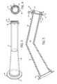
- FIG. 1is a plan side view of a container with an examplary embodiment of a child-resistant spout closure on a vent spout and on a fill spout.
- FIG. 2is a partial cut-away, side view of a spout with an examplary embodiment of a child-resistant spout closure illustrating a cap coupled to the spout with a tether.
- FIG. 3is a top perspective view of a spout.
- FIG. 4is an end perspective view of the distal end of the spout illustrated in FIG. 3 .
- FIG. 5is a sectional side view of a fill spout with an examplary child-resistant spout closure closing the opening of the spout.
- FIG. 6is a top view of an examplary embodiment of a cap of a child-resistant spout closure.
- FIG. 7is a sectional view of the cap illustrated in FIG. 6 along the line 7 — 7 .
- FIG. 8is a sectional view of the cap illustrated in FIG. 2 along the line 8 — 8 .
- FIG. 9is a bottom-plan view of an examplary embodiment of a child-resistant spout closure for a vent in a container.
- FIG. 10is a side plan view of the child-resistant spout closure illustrated in FIG. 9 and further illustrating a sectional view of the cap shown in FIG. 9 along the line 10 — 10 .
- FIG. 11is a top plan view of a child-resistant spout closure illustrated in FIG. 9 .
- FIG. 12is a partial cut-away side view of a spout configured to engage a closure member, with the closure member having an orifice sized to receive the spout and configured to threadingly engage the container and sealing the fill opening of the container.
- FIG. 1there is illustrated a side-plan view of a container 15 , also referred to as a vessel, having a spout 32 mounted on he container 15 and a vent 19 also mounted on the container 15 .
- the spout and ventare each in fluid communication with the interior 20 of the container 15 through a fill opening 18 (See FIG. 12 ).
- Each of the fill spout 32 and the vent 19have a child-resistant spout closure 30 sealing a distal end 34 of the child-resistant spout closure 30 .
- the container 15is configured to hold either a liquid or a solid material.
- the container 15is composed of material that is compatible as to structural and chemical characteristics, of the material it will contain.
- the containercan be manufactured by any suitable and convenient method such as blow molding.
- the containercan be made from any suitable material such as, for example, polyester, polyamide (example—nylon), polystyrene, acetyl, or polyoefinic materials, e.g., various grades of polyethylene or polypropylene or such other suitable material that is appropriate for the type of material, liquid or solid that will be contained in the container 15 .
- suitable materials for forming the containerinclude medium and high density grades of polyethylene.
- the spout 32 and the container 15can be integrally formed as a single unit during the manufacturing process.
- a spout 32having a distal end 34 and a proximate end 46 with the spout configured as an elongated hollow tube.
- the spout wall 44can be any suitable thickness with the spout 32 formed to provide an interior 40 which is in fluid communication with the interior 20 of the container 15 through a fill opening 18 in the container.
- the spout 32can be configured to be substantially straight along its full longitudinal length as shown in FIG. 10, or it can be substantially straight along its longitudinal length but taper to a smaller diameter at the distal end as compared to the diameter at its proximate end. It can also have a curve or bend midway between the proximal end and the distal end as shown in FIGS. 2 and 5.
- the child-resistant spout closure 30comprises a lip 36 defining a spout opening 38 .
- the spout opening 38is in fluid communication with the interior 40 of the spout.
- the lip 36defines a closure recess 42 extending through the lip 36 to the spout wall 44 . See FIGS. 4, 9 and 10 .
- the child-resistant spout closure 30also includes a cap 50 configured to fill the spout opening 38 , with the cap 50 having a lock nub 52 configured to engage the lip 36 and seal the spout opening 38 .
- the seal formed by the interface of the cap 50 within the spout opening 38is configured to withstand a minimum internal pressure of 20 pounds per square inch—gauge (psi-g).
- the sealmay also be formed by a gasket or o-ring, however, such seal must withstand a minimum internal pressure of 20 psi-g.
- the lock nub 52is also configured to selectively pass through the closure recess 42 when the lock nub 52 and the closure recess 42 are aligned. When the lock nub 52 and the closure recess 42 are so aligned, the cap 50 is removable from the spout 32 thereby allowing the material in the container 15 to be decanted or filled through the spout 32 .
- the container 15may also be provided with an additional opening for filling the container. Such additional opening will have its own closure.
- the lock nub 52is a protrusion formed on an interior wall of the cap (See FIGS. 8 and 2) with the lock nub 52 engaging the underside of the lip 36 which lip 36 has a truncated cone geometry and completely around the spout opening 38 on the distal end 34 of the spout 32 .
- the recess opening 42 and the lip 36are configured to correspond to the size of the lock nub 52 so that the lock nub 52 can pass through the closure recess 42 during the removal process described below.
- the cap 50forms a liquid tight seal with the spout opening 38 when the cap is engaged with the lip 36 of the spout 32 . (See FIG. 5)
- Another embodiment of the child-resistant spout closureincludes a ring 48 formed on the spout wall 44 a spaced apart distance from the lip 36 .
- the ring 48inhibits removal of the cap 50 when the cap 50 is engaged with the lip 36 and the lock nub 52 is not aligned with the closure recess 42 .
- FIGS. 2, 3 and 5With the cap in place on the distal end 34 of the spout 32 as shown in FIG. 5, and with the cap rotated to either side of the closure recess 42 so that the lock nub 52 is not aligned with the closure recess 42 it is not possible to lift the underside of the cap 50 because of the ring 48 . It is this feature that inhibits a child from removing the cap 50 from the spout 32 and accessing the material, hazardous or otherwise, from the interior of the container 15 .
- the child-resistant spout closureincludes a shelf 54 mounted on an exterior surface 56 of the cap 50 with the shelf 54 aligned with the lock nub 52 .
- the shelf 54is on an exterior sidewall of the cap 50 (See FIGS. 6 and 8 ).
- the shelf 54is aligned on the outside of the cap 50 with the lock nub 52 formed on the inside wall of the cap 50 as described above.
- Indicia 51 of the location of the lock nub 52can also be provided on the top surface of the cap 50 as shown in FIG. 6 which provides an indication as to where the cap 50 should be rotated to align with the closure recess 42 defined in the lip 36 .
- Spout indicia 33can be provided to indicate the location of the closure recess 42 (See FIG. 2 ).
- a tether 58couples the cap 50 to the spout 32 .
- the tether 58functions not only to couple the cap 50 with the spout 32 but also provides a biasing force which tends to rotate the cap 50 away from the closure recess 42 .
- an operatorTo open the cap 50 , an operator must rotate the cap 50 to align the lock nub 52 with the closure recess 42 , as facilitated by the cap indicia 51 and the spout indicia 33 .
- the rotation of the cap 50increases the bias force exerted by the tether 58 which inhibits the action of a child but not to the extent that an adult or an elderly person cannot overcome such bias force.
- an operatorcan apply a lifting force to the shelf 54 while maintaining the rotational force on the cap 50 and remove the cap 50 from the spout 32 .
- the tether 58retains the cap 50 .
- the operatorcan either fill or decant material to or from the container.
- the capcan be replaced on the distal end 34 of the spout 32 with the operator applying a force to the cap 50 until the lock nub 52 engages the lip 36 and seals the spout 32 .
- the lock nub 52will snap over the lip 36 and engage the underside of the lip to effect the fluid seal of the spout 32 .
- the tether 58again asserts a biasing force to rotate the cap so the lock nub 52 and the closure recess 42 are misaligned and the cap 50 cannot be removed.
- FIGS. 9-11Another embodiment of the child-resistant spout closure is illustrated in FIGS. 9-11.
- the spout 32is placed in an opening of the container wall 16 of the container 15 to provide a vent into the interior 20 of the container 15 .
- the proximate end 46 of the spout 32is placed in the opening 18 in the container wall 16 and is secured in place in any convenient fashion such as with a detent or an adhesive or a sonic weld or the like.
- the child-resistant spout closure 30functions as described above for a fill spout as to the opening and closing of the cap on the distal end 34 of the spout 32 .
- the vent 19functions to allow the ingress of air into the interior 20 of the container 15 to equalize pressure and allow the smooth flow of material through the fill spout. Since a child can access the interior 20 of the container 15 through the venting and thereby access the material contained in the container, an apparatus and method that will inhibit a child from opening the cap 50 is required.
- the present child-resistant spout closure 30provides such apparatus and method.
- the spout 32 , the cap 50 and the tether 58may be manufactured, such as by extrusion, with a somewhat stiff material such as acetal. It is also contemplated that such elements can be manufactured from the same type of material that the container 15 is made from. It is further contemplated that the spout 32 and the container 15 can be integrally formed as a single unit during the manufacturing process.
- the containercan be provided with a neck supporting a clutch ring having a clutch tab which includes a plurality of clutch teeth that engage a plurality of teeth on the closure member wherein the teeth of the closure member remain engaged with the clutch teeth until at least one clutch tab is moved away from the teeth of the closure member to further inhibit child access to the interior of the container.
- the containercan also be configured to provide for the spout to be threaded into the interior portion of the container.
- the fill spoutcan also be configured to be stored in the interior of the container with an appropriate closure member being provided with a plug to close the orifice in the closure member which was sized to engage the fill spout.
- an appropriate closure memberbeing provided with a plug to close the orifice in the closure member which was sized to engage the fill spout.
Landscapes
- Engineering & Computer Science (AREA)
- Mechanical Engineering (AREA)
- Closures For Containers (AREA)
Abstract
Description
Claims (18)
Priority Applications (1)
| Application Number | Priority Date | Filing Date | Title |
|---|---|---|---|
| US09/718,776US6575333B1 (en) | 2000-11-22 | 2000-11-22 | Child resistant spout closure |
Applications Claiming Priority (1)
| Application Number | Priority Date | Filing Date | Title |
|---|---|---|---|
| US09/718,776US6575333B1 (en) | 2000-11-22 | 2000-11-22 | Child resistant spout closure |
Publications (1)
| Publication Number | Publication Date |
|---|---|
| US6575333B1true US6575333B1 (en) | 2003-06-10 |
Family
ID=24887486
Family Applications (1)
| Application Number | Title | Priority Date | Filing Date |
|---|---|---|---|
| US09/718,776Expired - Fee RelatedUS6575333B1 (en) | 2000-11-22 | 2000-11-22 | Child resistant spout closure |
Country Status (1)
| Country | Link |
|---|---|
| US (1) | US6575333B1 (en) |
Cited By (19)
| Publication number | Priority date | Publication date | Assignee | Title |
|---|---|---|---|---|
| US20050006396A1 (en)* | 2003-07-09 | 2005-01-13 | Unkenholz Brian Edward | Drinking vessel |
| US20070102484A1 (en)* | 2005-11-10 | 2007-05-10 | Baldwin Don | Angled caulking tip attachment |
| US20110079058A1 (en)* | 2009-09-28 | 2011-04-07 | Nielsen Simon S | Locking Top for Container |
| US8397960B1 (en) | 2009-12-16 | 2013-03-19 | Woodrow Wilson Farrar, Jr. | Dispensing and sealing assembly for container |
| US20130144235A1 (en)* | 2008-07-08 | 2013-06-06 | Tyco Healthcare Group Lp | Portable Negative Pressure Wound Therapy Device |
| US20140103078A1 (en)* | 2012-10-04 | 2014-04-17 | Nathan Wright | Spout with controlled fluid flow for portable fuel containers |
| US8800826B2 (en) | 2012-07-17 | 2014-08-12 | Scepter Manufacturing, Llc | Self-venting spout |
| US9956327B2 (en) | 2007-07-02 | 2018-05-01 | Smith & Nephew Plc | Wound treatment apparatus with exudate volume reduction by heat |
| US9974890B2 (en) | 2008-05-21 | 2018-05-22 | Smith & Nephew, Inc. | Wound therapy system and related methods therefor |
| US10004835B2 (en) | 2008-09-05 | 2018-06-26 | Smith & Nephew, Inc. | Canister membrane for wound therapy system |
| US10071190B2 (en) | 2008-02-27 | 2018-09-11 | Smith & Nephew Plc | Fluid collection |
| US10130526B2 (en) | 2006-09-28 | 2018-11-20 | Smith & Nephew, Inc. | Portable wound therapy system |
| US10737000B2 (en) | 2008-08-21 | 2020-08-11 | Smith & Nephew, Inc. | Sensor with electrical contact protection for use in fluid collection canister and negative pressure wound therapy systems including same |
| US10744239B2 (en) | 2014-07-31 | 2020-08-18 | Smith & Nephew, Inc. | Leak detection in negative pressure wound therapy system |
| US10912869B2 (en) | 2008-05-21 | 2021-02-09 | Smith & Nephew, Inc. | Wound therapy system with related methods therefor |
| US11472613B2 (en) | 2019-04-23 | 2022-10-18 | Berry Global, Inc. | Selectively openable closure for a container |
| US11471571B2 (en) | 2017-04-19 | 2022-10-18 | Smith & Nephew, Inc. | Negative pressure wound therapy canisters |
| US12133789B2 (en) | 2014-07-31 | 2024-11-05 | Smith & Nephew, Inc. | Reduced pressure therapy apparatus construction and control |
| US12280203B2 (en) | 2019-10-03 | 2025-04-22 | T.J.Smith And Nephew, Limited | Apparatuses and methods for negative pressure wound therapy |
Citations (8)
| Publication number | Priority date | Publication date | Assignee | Title |
|---|---|---|---|---|
| US3584760A (en) | 1969-07-22 | 1971-06-15 | William A Grinker | Safety caps for containers |
| US3765578A (en) | 1972-08-28 | 1973-10-16 | Stull Engraving Co | Twist release safety cap |
| US3865267A (en)* | 1973-12-20 | 1975-02-11 | Glenn H Morris | Child-proof and pharmacist-assisting reversible closure for containers |
| US3877598A (en)* | 1974-02-25 | 1975-04-15 | Polytop Corp | Closure structures having child-safety feature |
| US4281778A (en)* | 1980-01-18 | 1981-08-04 | Morton Stull | Locking closure cap |
| US4334639A (en)* | 1979-12-31 | 1982-06-15 | Sunbeam Plastics Corporation | Child-resistant dispensing closure |
| US5292017A (en) | 1993-01-26 | 1994-03-08 | Calmar Inc. | Child-resistant closure with easy opening feature |
| US5593054A (en) | 1995-04-28 | 1997-01-14 | Ideal Ideas, Inc. | Child resistant flip cap with collar |
- 2000
- 2000-11-22USUS09/718,776patent/US6575333B1/ennot_activeExpired - Fee Related
Patent Citations (8)
| Publication number | Priority date | Publication date | Assignee | Title |
|---|---|---|---|---|
| US3584760A (en) | 1969-07-22 | 1971-06-15 | William A Grinker | Safety caps for containers |
| US3765578A (en) | 1972-08-28 | 1973-10-16 | Stull Engraving Co | Twist release safety cap |
| US3865267A (en)* | 1973-12-20 | 1975-02-11 | Glenn H Morris | Child-proof and pharmacist-assisting reversible closure for containers |
| US3877598A (en)* | 1974-02-25 | 1975-04-15 | Polytop Corp | Closure structures having child-safety feature |
| US4334639A (en)* | 1979-12-31 | 1982-06-15 | Sunbeam Plastics Corporation | Child-resistant dispensing closure |
| US4281778A (en)* | 1980-01-18 | 1981-08-04 | Morton Stull | Locking closure cap |
| US5292017A (en) | 1993-01-26 | 1994-03-08 | Calmar Inc. | Child-resistant closure with easy opening feature |
| US5593054A (en) | 1995-04-28 | 1997-01-14 | Ideal Ideas, Inc. | Child resistant flip cap with collar |
Cited By (27)
| Publication number | Priority date | Publication date | Assignee | Title |
|---|---|---|---|---|
| US20050006396A1 (en)* | 2003-07-09 | 2005-01-13 | Unkenholz Brian Edward | Drinking vessel |
| US20070102484A1 (en)* | 2005-11-10 | 2007-05-10 | Baldwin Don | Angled caulking tip attachment |
| US11141325B2 (en) | 2006-09-28 | 2021-10-12 | Smith & Nephew, Inc. | Portable wound therapy system |
| US12115302B2 (en) | 2006-09-28 | 2024-10-15 | Smith & Nephew, Inc. | Portable wound therapy system |
| US10130526B2 (en) | 2006-09-28 | 2018-11-20 | Smith & Nephew, Inc. | Portable wound therapy system |
| US9956327B2 (en) | 2007-07-02 | 2018-05-01 | Smith & Nephew Plc | Wound treatment apparatus with exudate volume reduction by heat |
| US10071190B2 (en) | 2008-02-27 | 2018-09-11 | Smith & Nephew Plc | Fluid collection |
| US12201764B2 (en) | 2008-02-27 | 2025-01-21 | Smith & Nephew Plc | Fluid collection |
| US11141520B2 (en) | 2008-02-27 | 2021-10-12 | Smith & Nephew Plc | Fluid collection |
| US9974890B2 (en) | 2008-05-21 | 2018-05-22 | Smith & Nephew, Inc. | Wound therapy system and related methods therefor |
| US10967106B2 (en) | 2008-05-21 | 2021-04-06 | Smith & Nephew, Inc. | Wound therapy system and related methods therefor |
| US10912869B2 (en) | 2008-05-21 | 2021-02-09 | Smith & Nephew, Inc. | Wound therapy system with related methods therefor |
| US20130144235A1 (en)* | 2008-07-08 | 2013-06-06 | Tyco Healthcare Group Lp | Portable Negative Pressure Wound Therapy Device |
| US10737000B2 (en) | 2008-08-21 | 2020-08-11 | Smith & Nephew, Inc. | Sensor with electrical contact protection for use in fluid collection canister and negative pressure wound therapy systems including same |
| US10004835B2 (en) | 2008-09-05 | 2018-06-26 | Smith & Nephew, Inc. | Canister membrane for wound therapy system |
| US20110079058A1 (en)* | 2009-09-28 | 2011-04-07 | Nielsen Simon S | Locking Top for Container |
| US8397960B1 (en) | 2009-12-16 | 2013-03-19 | Woodrow Wilson Farrar, Jr. | Dispensing and sealing assembly for container |
| US8800826B2 (en) | 2012-07-17 | 2014-08-12 | Scepter Manufacturing, Llc | Self-venting spout |
| US20140103078A1 (en)* | 2012-10-04 | 2014-04-17 | Nathan Wright | Spout with controlled fluid flow for portable fuel containers |
| US20160304253A1 (en)* | 2012-10-04 | 2016-10-20 | Nathan Wright | Spout with controlled fluid flow for portable containers |
| US10744239B2 (en) | 2014-07-31 | 2020-08-18 | Smith & Nephew, Inc. | Leak detection in negative pressure wound therapy system |
| US12115298B2 (en) | 2014-07-31 | 2024-10-15 | Smith & Nephew, Inc. | Wound pressure determination for reduced pressure wound therapy |
| US12133789B2 (en) | 2014-07-31 | 2024-11-05 | Smith & Nephew, Inc. | Reduced pressure therapy apparatus construction and control |
| US11471571B2 (en) | 2017-04-19 | 2022-10-18 | Smith & Nephew, Inc. | Negative pressure wound therapy canisters |
| US11472613B2 (en) | 2019-04-23 | 2022-10-18 | Berry Global, Inc. | Selectively openable closure for a container |
| US11691794B2 (en) | 2019-04-23 | 2023-07-04 | Berry Global, Inc. | Selectively openable closure for a container |
| US12280203B2 (en) | 2019-10-03 | 2025-04-22 | T.J.Smith And Nephew, Limited | Apparatuses and methods for negative pressure wound therapy |
Similar Documents
| Publication | Publication Date | Title |
|---|---|---|
| US6575333B1 (en) | Child resistant spout closure | |
| US4834271A (en) | One-piece dispensing closure | |
| JP6061921B2 (en) | Container closure having means for introducing additives into the contents of the container | |
| US4854483A (en) | Packages for carbonated beverages | |
| US5358148A (en) | Urine collection container | |
| US20090321286A1 (en) | Container closure having a lifting cap for introducing an additive into the contents of the container | |
| US6571972B1 (en) | Bulk drum lid with two bung openings | |
| US4325496A (en) | Filling-dispensing closure for a bag-like container | |
| US5123555A (en) | Container cap having external bead | |
| US4043474A (en) | Child resistant closure for a container | |
| US11465898B2 (en) | Catch releasing capless fuel-filler bottle | |
| US4066191A (en) | Drinking and pouring spout for use with easy-opening containers | |
| US3642172A (en) | Bulk containers | |
| US4111331A (en) | Tamper-proof closure device | |
| US4925063A (en) | Container having a dual purpose cap and a dripless spout | |
| US20030155321A1 (en) | Bottle and bottle closure assembly | |
| US6073809A (en) | Snap-on tamper evident closure with push-pull pour spout | |
| US5184747A (en) | Seal engaging ring | |
| WO1995015283A2 (en) | Refillable package | |
| US4706855A (en) | One-piece container closure of the dispensing type | |
| US6283331B1 (en) | Contact opening cap for bottles | |
| WO2002019959A1 (en) | Sealing membrane for baby bottle or other fluid container | |
| US5975339A (en) | Disposable containers and insert rim therefore | |
| CA2662009A1 (en) | Beverage container closure and dispensing device | |
| US11993425B2 (en) | Cap for dispensing liquids from a container |
Legal Events
| Date | Code | Title | Description |
|---|---|---|---|
| AS | Assignment | Owner name:WESTERN INDUSTRIES, INC., WISCONSIN Free format text:ASSIGNMENT OF ASSIGNORS INTEREST;ASSIGNOR:RABOIN, RONALD K.;REEL/FRAME:011329/0059 Effective date:20001121 | |
| AS | Assignment | Owner name:BANK OF NOVA SCOTIA,THE, AS ADMINISTRATIVE AGENT, Free format text:SECURITY INTEREST;ASSIGNOR:WESTERN INDUSTRIES, INC.;REEL/FRAME:011855/0098 Effective date:20010430 | |
| AS | Assignment | Owner name:BLITZ U.S.A., INC., OKLAHOMA Free format text:ASSIGNMENT OF ASSIGNORS INTEREST;ASSIGNOR:WESTERN INDUSTRIES, INC.;REEL/FRAME:015494/0800 Effective date:20040713 | |
| AS | Assignment | Owner name:WESTERN INDUSTRIES, INC., WISCONSIN Free format text:RELEASE OF SECURITY INTEREST;ASSIGNOR:BANK OF NOVA SCOTIA, THE;REEL/FRAME:016116/0603 Effective date:20041229 | |
| FEPP | Fee payment procedure | Free format text:PAT HOLDER CLAIMS SMALL ENTITY STATUS, ENTITY STATUS SET TO SMALL (ORIGINAL EVENT CODE: LTOS); ENTITY STATUS OF PATENT OWNER: SMALL ENTITY | |
| REFU | Refund | Free format text:REFUND - PAYMENT OF MAINTENANCE FEE, 4TH YEAR, LARGE ENTITY (ORIGINAL EVENT CODE: R1551); ENTITY STATUS OF PATENT OWNER: SMALL ENTITY | |
| FEPP | Fee payment procedure | Free format text:PAYOR NUMBER ASSIGNED (ORIGINAL EVENT CODE: ASPN); ENTITY STATUS OF PATENT OWNER: SMALL ENTITY | |
| FPAY | Fee payment | Year of fee payment:4 | |
| REMI | Maintenance fee reminder mailed | ||
| LAPS | Lapse for failure to pay maintenance fees | ||
| STCH | Information on status: patent discontinuation | Free format text:PATENT EXPIRED DUE TO NONPAYMENT OF MAINTENANCE FEES UNDER 37 CFR 1.362 | |
| FP | Lapsed due to failure to pay maintenance fee | Effective date:20110610 |