US6575311B1 - Golf club display rack - Google Patents
Golf club display rackDownload PDFInfo
- Publication number
- US6575311B1 US6575311B1US10/156,290US15629002AUS6575311B1US 6575311 B1US6575311 B1US 6575311B1US 15629002 AUS15629002 AUS 15629002AUS 6575311 B1US6575311 B1US 6575311B1
- Authority
- US
- United States
- Prior art keywords
- golf club
- support surface
- display rack
- rack
- spaced
- Prior art date
- Legal status (The legal status is an assumption and is not a legal conclusion. Google has not performed a legal analysis and makes no representation as to the accuracy of the status listed.)
- Expired - Fee Related
Links
- 238000010276constructionMethods0.000claimsdescription4
- 230000000712assemblyEffects0.000claims9
- 238000000429assemblyMethods0.000claims9
- 239000000463materialSubstances0.000abstractdescription8
- 230000000717retained effectEffects0.000description8
- 239000006260foamSubstances0.000description4
- 239000004744fabricSubstances0.000description2
- 238000000926separation methodMethods0.000description2
- 229920005830Polyurethane FoamPolymers0.000description1
- 230000008676importEffects0.000description1
- 238000012986modificationMethods0.000description1
- 230000004048modificationEffects0.000description1
- 239000011496polyurethane foamSubstances0.000description1
- 230000000087stabilizing effectEffects0.000description1
Images


Classifications
- A—HUMAN NECESSITIES
- A47—FURNITURE; DOMESTIC ARTICLES OR APPLIANCES; COFFEE MILLS; SPICE MILLS; SUCTION CLEANERS IN GENERAL
- A47F—SPECIAL FURNITURE, FITTINGS, OR ACCESSORIES FOR SHOPS, STOREHOUSES, BARS, RESTAURANTS OR THE LIKE; PAYING COUNTERS
- A47F7/00—Show stands, hangers, or shelves, adapted for particular articles or materials
- A47F7/0021—Show stands, hangers, or shelves, adapted for particular articles or materials for long or non-stable articles, e.g. fishing rods, pencils, lipsticks or the like; Compartments or recesses as stabilising means
- A47F7/0028—Show stands, hangers, or shelves, adapted for particular articles or materials for long or non-stable articles, e.g. fishing rods, pencils, lipsticks or the like; Compartments or recesses as stabilising means with one compartment or recess for each article
Definitions
- the present inventionrelates to a display rack for golf clubs. Specifically, the present invention is directed towards a golf club display rack which supports the golf clubs by the head of the golf club and allows the club shaft to hang there below in parallel fashion.
- the present inventionis directed towards a golf club display rack which allows the golf clubs to be supported by the head of the golf club in an orderly and appealing fashion while also stabilizing the shaft so that the entire display organizes the shafts in a parallel manner.
- the present inventionfurther provides for a golf club display rack which supports the golf club at both a first and a second position.
- An additional object of the present inventionis to provide a golf club display rack which allows for ready support of the golf club head while firmly retaining the entire shaft in a pre-desired position.
- An additional object of the present inventionis to provide a golf club display rack wherein the display rack may have an upper support surface and a lower support surface wherein the upper support surface may support the golf club head and the lower support surface may retain the golf club shaft, and further wherein the entirety of the golf club display rack is integrated into a single compact support mechanism.
- a further object of the present inventionis to provide a golf club head alignment bar on a golf club display rack wherein the golf club head alignment bar organizes the golf club heads and allows the shafts to depend directly therefrom in an orderly fashion to be retained by a lower supporting surface.
- An even further object of the present inventionis to provide a golf club display rack which may be integrated on either a wall mounting position or in a stand alone rack mount position such that golf clubs may be displayed in parallel fashion and wherein a plurality of clubs may be readily displayed.
- An additional object of the present inventionis to provide a multi-leveled golf club display rack wherein a plurality of clubs may be readily displayed in organized fashions such that the golf club shafts remain in a parallel fashion to each other and wherein a plurality of levels for supporting the golf clubs may be provided in a single display rack.
- the present inventionprovides for display of golf clubs in an organized fashion such that the golf club shafts are displayed in a parallel manner and such that the entirety of the display rack and support device is located near the head of the golf club.
- the present inventionis therefore directed towards a golf club display rack which may provide for a plurality of levels or tiers upon which golf clubs may be organized.
- the rackmay be constructed as a side-turned U-shaped or C-shaped display assembly or rack, wherein an upper support surface holds the golf club head in place.
- Extending below the upper support surfacemay be a lower support surface which firmly retains the shaft of the club near the hosel of the club head.
- the lower support surfaceis constructed so as a portion thereof crimps or pinches the shaft and firmly holds it in place. This may be completed through the use of a layer of foam like compressible material which has a slot formed therein to receive the shaft.
- the club headis held in the rack and aligned by an alignment bar while the shaft is retained at a position near the hosel to maintain the shafts in congruent vertical position.
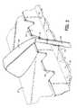
- FIG. 1is a perspective view of the golf club display rack of the present invention.
- FIG. 2is a top perspective close up view of the support structure for the golf club display rack shown in FIG. 1;
- FIG. 3is a side cut away view of the golf club display rack shown in FIG. 1;
- FIG. 4is a front view of the golf club display rack of the present invention.
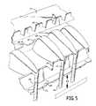
- FIG. 5is a close up perspective view of the golf club display rack of the present invention.
- the golf club display rack 10 of the present inventionis disclosed in FIG. 1 .
- the golf club display rackmay be comprised of a plurality of tiers 51 , 52 , 53 .
- Each of the plurality of tiersmay be comprised of left hand display racks 20 and right hand display racks 21 so that a gap may exist there between.
- the golf club display rack 10 of the present invention as depicted in FIG. 1shows how each of the left hand racks 20 and right hand racks 21 may be integrated with side frame members 22 so that golf clubs may be properly restrained therein, the club heads are fully supported and the shafts remain in parallel relationship.
- Each of the left hand racks 20 and right hand racks 21are similarly constructed so discussion of one may be applicable to the other. Additionally, as depicted in FIG. 1, the left hand rack and right hand rack, 20 , 21 are shown with a separation there between. Alternatively, full length individual racks may be provided which extend entirely between side frame members 22 . Such alternatives are considered to be within the teaching of the disclosure herein and no unnecessary limitations are to be interpreted from the examples shown in the figures.
- the left hand rack 20is comprised of a side turned U-shaped or C-shaped structure or assembly which has an upper support surface 44 , a lower support surface 24 and a rear wall 43 forming cavity 26 which may be seen in FIG. 3 .
- the rear wall 43extends between the upper support surface 44 and the lower support surface 24 .
- the upper support surface 44is provided such that it may support the golf club thereon as is shown in FIG. 2 and in FIG. 3 .
- the golf club head 40is supported by the upper support surface 44 and may additionally rest on the club support 27 .
- the club support 27may be an extra layer placed upon the upper support surface 44 in order to provide a soft surface for the golf club head 40 to rest upon.
- the club support 27may be made of a foam, cloth or other material or may similarly be integrated directly with the upper support surface 44 such that a single integral surface is provided.
- the upper support surface 44extends outward from the rear wall 43 to a point where a club head alignment bar 25 extends upwardly therefrom.
- the golf supporting rack 20depicted as a left hand rack in FIG. 1, is thus comprised of a club head alignment bar 25 which may be substantially vertical, an upper support surface 44 which extends rearward from said alignment bar 25 to a rear wall 43 , the rear wall 43 extending downward therefrom then connecting to a lower support surface 24 which extends forward from said rear wall 43 and is spaced below said upper support surface 44 .
- the golf club head alignment bar 25which extends across the front or leading edge of the upper support surface 44 , has a plurality of alignment notches 29 formed therein. As seen in FIG.
- the alignment notchesare sized such that the golf club head 40 may rest securely on the club support 27 while the hosel 41 extends outward from said alignment notch 29 allowing the golf club shaft 42 to depend downward therefrom.
- the golf club shaft 42is spaced outwardly from the alignment bar 25 and extends downwardly in front of the upper support surface 44 .
- the lower support surface 24may have a retaining surface 28 formed thereon of an additional material similar to club support 27 .
- Retaining surface 28may be comprised of foam, cloth or other material or may again be integrated directly with lower support surface 24 .
- the lower support surface 24extends outward in spaced relationship beyond the upper support surface 44 .
- Retaining surface 28may extend nearly to the edge of lower support surface 24 .
- Lower support surface 24additionally has a plurality of notches 32 formed therein which receive the club shaft 42 .
- the retaining surface 28actually extends over the notch 32 of the lower support surface 24 and may have a slot 33 formed therein.
- One preferred slot 33has an inward tapered configuration.
- the retaining surface 28if comprised of a foam or other compressible material, receives the golf club shaft 42 within the slot 33 to securely hold the shaft within the notch 32 such that the shafts of all of the clubs held within the golf club display rack 10 are in parallel form.
- the notch 32 formed in the lower support surfacewhich is separated from the upper support surface 44 by cavity 26 (FIG. 1) works in conjunction with alignment bar 25 so that the club head is securely retained against the upper support surface 44 in conjunction with retaining the club shaft 42 .
- a plurality of clubsmay be retained on each of the different levels or tiers 51 , 52 , 53 of the golf club display rack 10 of the present invention.
- Each of the levels of the golf club display rackmay be comprised of either a left hand rack 20 and a right hand rack 21 or may be comprised of a singular rack extending between the side frame members 22 .
- Each of the individual levels or tiersare separated from the next adjacent tier by a separation gap 45 shown in FIG. 5 .
- top or first tier 51is disposed behind and slightly above second level or tier 52 and separated by a gap 45
- second tier 52is disposed above and slightly behind third or lower tier 53 .
- Each of the tiers or levelsis separated from the next adjacent level by the gap 45 so that the clubs may be readily inserted within the club head alignment bar 25 for each of the tiers 51 , 52 , 53 .
- the golf club display rack 10 of the present inventionwhich supports a plurality of golf clubs.
- Each of the C-shaped racks 20 and 21securely holds golf club shafts 42 in parallel relationship.
- the alignment bar 25may have a plurality of alignment notches 29 thereon, each of the alignment notches sized so as to retain the hosel 41 in front thereof.
- the plurality of alignment notches 29 formed in the alignment bar 25may be alternatively sized to varying degrees so that different size clubs may fit through an alignment notch 29 and the club head 40 may securely rest on the club support 27 .
- a smaller alignment notch 29may be provided for clubs with a wider club head angle such as lofted clubs.
- narrow alignment notches 29may be provided in the club support 27 for clubs wherein the club head 40 is near vertical.
- the club support 27allows the club head 40 to rest thereon and allows hosel 41 to extend outward through the alignment notch 29 formed in the alignment bar 25 .
- the club shaft 42may extend downwardly therefrom through the retaining surface 28 and the notch formed in the lower support surface 24 such that the retaining surface 28 partially wraps around the club shaft 42 and holds it securely in place. It may be preferable that the shaft 42 extends firmly within the slot 33 formed in surface 28 .
- surface 28may be formed such that grooves or slits are formed therein that may tightly retain the shaft 42 , particularly when the retaining surface 28 is made of a compressible material such as a polyurethane foam or other known materials.
- a compressible materialsuch as a polyurethane foam or other known materials.
- the shaft 42is retained in place in a secure fashion such that the shaft 42 of the plurality of clubs retained on the golf club display rack 10 are held in parallel fashion in an organized form.
- a plurality of tiers 51 , 52 and 53may be provided in order that a number of clubs may be displayed at various levels.
- the side frame 22may extend upwardly at a slight angle from the forward most end to the rear most end.
- each of the tiersare thereby placed one above the other such that each row or tier allows the one in front to be visible.
- the clubs retained on the lower most tier 53do not get in the way of the view of any other clubs placed on the higher tiers.
- the golf club display rackmay be secured to a number of support brackets 31 on the rear end of side frame member 22 . Additionally, a rear support member may be provided extending behind the upper most tier 51 and between the side frame members 22 . As shown in FIG. 1, the golf display rack 10 may be supported by a number of support brackets 31 located along a rear portion thereof. The support brackets 31 may be such that the golf display rack 10 may be mounted to a wall or other vertical surface. Additionally, the brackets may be provided for mounting on a stand alone support frame such that the display rack 10 is suspended or supported along a rear portion thereof and such that the golf clubs depend therebelow.
- the rear frame member 45which extends between the side frames 22 shown in FIG. 4 may be used to fully or firmly support the display rack.
- the golf club display rack 10 of the present inventionis thus comprised of individual C-shaped racks which have an upper surface and a lower surface, the upper surface utilized to support the golf club head and the retaining surface utilized to secure the golf club shaft directly below the hosel such that the golf club shaft for a plurality of clubs supported on the rack are held in parallel fashion.
- the display rack presented hereinprovides for congruent display of the clubs in an organized fashion such that the shafts are maintained vertically.
- the rackwhile described herein as being of C-shaped construction, may also be an upper and a lower support surface which are in proper alignment with respect to each other in order to achieve the same functionality.
Landscapes
- Golf Clubs (AREA)
Abstract
Description
Claims (15)
Priority Applications (1)
| Application Number | Priority Date | Filing Date | Title |
|---|---|---|---|
| US10/156,290US6575311B1 (en) | 2002-01-24 | 2002-05-28 | Golf club display rack |
Applications Claiming Priority (2)
| Application Number | Priority Date | Filing Date | Title |
|---|---|---|---|
| US35162902P | 2002-01-24 | 2002-01-24 | |
| US10/156,290US6575311B1 (en) | 2002-01-24 | 2002-05-28 | Golf club display rack |
Publications (1)
| Publication Number | Publication Date |
|---|---|
| US6575311B1true US6575311B1 (en) | 2003-06-10 |
Family
ID=26853038
Family Applications (1)
| Application Number | Title | Priority Date | Filing Date |
|---|---|---|---|
| US10/156,290Expired - Fee RelatedUS6575311B1 (en) | 2002-01-24 | 2002-05-28 | Golf club display rack |
Country Status (1)
| Country | Link |
|---|---|
| US (1) | US6575311B1 (en) |
Cited By (19)
| Publication number | Priority date | Publication date | Assignee | Title |
|---|---|---|---|---|
| US20030055371A1 (en)* | 1998-01-30 | 2003-03-20 | Percardia, Inc. | Left ventricular conduits to coronary arteries and methods for coronary bypass |
| US20040245133A1 (en)* | 2003-06-05 | 2004-12-09 | Heidenreich David C. | Golf club holder |
| US20060207899A1 (en)* | 2003-04-30 | 2006-09-21 | Yukihiro Handa | Golf bag |
| US20070193965A1 (en)* | 2006-02-06 | 2007-08-23 | Alexander Plastics, Inc. | Reversible golf club holder |
| US20110174751A1 (en)* | 2006-11-13 | 2011-07-21 | Cormark, Inc. | Golf club holder and display |
| US8162156B1 (en)* | 2009-06-29 | 2012-04-24 | Bruce Crisman | Implement holder and methods of use |
| US20140001329A1 (en)* | 2012-06-27 | 2014-01-02 | Illinois Tool Works Inc. | Wall-Mountable Holder System |
| US8807501B2 (en)* | 2012-06-27 | 2014-08-19 | Illinois Tool Works Inc. | Wall-mountable holder |
| US20150018113A1 (en)* | 2013-07-11 | 2015-01-15 | Fu-Hsing Tan | Magnetic attraction type golf iron rack for golf bag |
| US20160157606A1 (en)* | 2014-12-08 | 2016-06-09 | Corning Incorporated | Apparatus for holding and retaining glass articles |
| US9845263B2 (en) | 2015-01-23 | 2017-12-19 | Corning Incorporated | Apparatuses for holding and retaining glass articles |
| US9908676B2 (en) | 2014-08-11 | 2018-03-06 | Corning Incorporated | Magazine apparatuses for holding glassware during processing |
| US9914200B2 (en) | 2014-08-08 | 2018-03-13 | Corning Incorporated | Magazine apparatuses for holding glass articles during processing |
| CN109588915A (en)* | 2018-12-27 | 2019-04-09 | 江苏红人实业股份有限公司 | A kind of Multifunctional golf ball bar showing stand |
| US10669195B2 (en) | 2015-05-11 | 2020-06-02 | Corning Incorporated | Apparatuses and methods for holding, retaining, and/or processing glassware articles |
| DE102021121588A1 (en) | 2021-08-19 | 2023-02-23 | MICROSTEP GmbH Schrittmotoren, Steuerungen, Bewegungssysteme | Device for the exact dosing of a fluid, dosing system and method for the exact dosing of a fluid |
| US11685039B1 (en)* | 2022-01-25 | 2023-06-27 | Woodpeckers, Llc | Router bit rack, system and method thereof |
| US11752616B2 (en) | 2022-01-25 | 2023-09-12 | Woodpeckers, Llc | Router bit rack, system and method thereof |
| KR20240054494A (en)* | 2022-10-19 | 2024-04-26 | 김미정 | Golf iron cover holder combing the functions of storing iron covers for golf, preventing loss and improving activity |
Citations (25)
| Publication number | Priority date | Publication date | Assignee | Title |
|---|---|---|---|---|
| US553445A (en) | 1896-01-21 | Ax-rack | ||
| US1678353A (en)* | 1927-07-02 | 1928-07-24 | Spalding & Bros Ag | Holder for golf clubs |
| US1719360A (en) | 1926-02-26 | 1929-07-02 | Deike Ulric Carl | Golf-club rack |
| US1849610A (en) | 1928-02-16 | 1932-03-15 | Edmund Quincy Moses | Golf bag |
| US2089537A (en)* | 1936-10-10 | 1937-08-10 | Philip T Champlin | Knife rack |
| US2436687A (en) | 1945-02-01 | 1948-02-24 | Corbett Robert Lee | Club head retaining means for golf club bags |
| US2577988A (en)* | 1948-09-11 | 1951-12-11 | Advertising Metal Display Co | Display board |
| US2754008A (en)* | 1953-08-13 | 1956-07-10 | Chas D Briddell Inc | Knife holder |
| US3721348A (en)* | 1971-07-08 | 1973-03-20 | R Cook | Means for supporting tools |
| US4027799A (en)* | 1975-06-18 | 1977-06-07 | The Gates Rubber Company | V-belt display hook |
| US4134499A (en) | 1975-09-26 | 1979-01-16 | Wolf-Gerate Gmbh | Tool holder |
| US4200131A (en)* | 1976-03-15 | 1980-04-29 | Chitwood Ernest L | Device for carrying golf clubs |
| US4421240A (en)* | 1981-08-03 | 1983-12-20 | Wittek Golf Range Supply Co. | Golf club display rack |
| US4830198A (en)* | 1988-04-21 | 1989-05-16 | Colquitt Albert D | Airbrush holder |
| US4863019A (en) | 1988-06-14 | 1989-09-05 | Lewis Elmer R | Golf bag lock |
| US4863020A (en)* | 1988-03-24 | 1989-09-05 | Klemow Jerry R | Spark plug wire hanger device |
| US5228566A (en) | 1992-04-28 | 1993-07-20 | Wilson Sporting Goods Co. | Golf bag top and club separator |
| US5383555A (en) | 1993-05-19 | 1995-01-24 | Weinmeier; Robert J. | Golf club securer and organizer |
| US5505316A (en) | 1994-07-29 | 1996-04-09 | Kwi Jun Enterprise Limited | Adjustable wrench-rack |
| US5526941A (en)* | 1994-03-31 | 1996-06-18 | Ford; Allan L. | Suspender display fixture |
| US5611440A (en) | 1994-05-17 | 1997-03-18 | Ryslinge Traevarer Aps | Sales rack for kitchen utensils |
| US5617951A (en) | 1996-01-23 | 1997-04-08 | Wick; Philip B. | Golf club organizer for a golf bag |
| US5620091A (en) | 1993-09-29 | 1997-04-15 | Larson; Gordon E. | Golf bag club holder |
| US5678700A (en)* | 1996-02-27 | 1997-10-21 | Crosson, Jr.; Oliver J. | Reel and rod hanger |
| US6041947A (en) | 1998-04-27 | 2000-03-28 | Heneveld; William R. | Storage rack for elongated items |
- 2002
- 2002-05-28USUS10/156,290patent/US6575311B1/ennot_activeExpired - Fee Related
Patent Citations (25)
| Publication number | Priority date | Publication date | Assignee | Title |
|---|---|---|---|---|
| US553445A (en) | 1896-01-21 | Ax-rack | ||
| US1719360A (en) | 1926-02-26 | 1929-07-02 | Deike Ulric Carl | Golf-club rack |
| US1678353A (en)* | 1927-07-02 | 1928-07-24 | Spalding & Bros Ag | Holder for golf clubs |
| US1849610A (en) | 1928-02-16 | 1932-03-15 | Edmund Quincy Moses | Golf bag |
| US2089537A (en)* | 1936-10-10 | 1937-08-10 | Philip T Champlin | Knife rack |
| US2436687A (en) | 1945-02-01 | 1948-02-24 | Corbett Robert Lee | Club head retaining means for golf club bags |
| US2577988A (en)* | 1948-09-11 | 1951-12-11 | Advertising Metal Display Co | Display board |
| US2754008A (en)* | 1953-08-13 | 1956-07-10 | Chas D Briddell Inc | Knife holder |
| US3721348A (en)* | 1971-07-08 | 1973-03-20 | R Cook | Means for supporting tools |
| US4027799A (en)* | 1975-06-18 | 1977-06-07 | The Gates Rubber Company | V-belt display hook |
| US4134499A (en) | 1975-09-26 | 1979-01-16 | Wolf-Gerate Gmbh | Tool holder |
| US4200131A (en)* | 1976-03-15 | 1980-04-29 | Chitwood Ernest L | Device for carrying golf clubs |
| US4421240A (en)* | 1981-08-03 | 1983-12-20 | Wittek Golf Range Supply Co. | Golf club display rack |
| US4863020A (en)* | 1988-03-24 | 1989-09-05 | Klemow Jerry R | Spark plug wire hanger device |
| US4830198A (en)* | 1988-04-21 | 1989-05-16 | Colquitt Albert D | Airbrush holder |
| US4863019A (en) | 1988-06-14 | 1989-09-05 | Lewis Elmer R | Golf bag lock |
| US5228566A (en) | 1992-04-28 | 1993-07-20 | Wilson Sporting Goods Co. | Golf bag top and club separator |
| US5383555A (en) | 1993-05-19 | 1995-01-24 | Weinmeier; Robert J. | Golf club securer and organizer |
| US5620091A (en) | 1993-09-29 | 1997-04-15 | Larson; Gordon E. | Golf bag club holder |
| US5526941A (en)* | 1994-03-31 | 1996-06-18 | Ford; Allan L. | Suspender display fixture |
| US5611440A (en) | 1994-05-17 | 1997-03-18 | Ryslinge Traevarer Aps | Sales rack for kitchen utensils |
| US5505316A (en) | 1994-07-29 | 1996-04-09 | Kwi Jun Enterprise Limited | Adjustable wrench-rack |
| US5617951A (en) | 1996-01-23 | 1997-04-08 | Wick; Philip B. | Golf club organizer for a golf bag |
| US5678700A (en)* | 1996-02-27 | 1997-10-21 | Crosson, Jr.; Oliver J. | Reel and rod hanger |
| US6041947A (en) | 1998-04-27 | 2000-03-28 | Heneveld; William R. | Storage rack for elongated items |
Cited By (22)
| Publication number | Priority date | Publication date | Assignee | Title |
|---|---|---|---|---|
| US20030055371A1 (en)* | 1998-01-30 | 2003-03-20 | Percardia, Inc. | Left ventricular conduits to coronary arteries and methods for coronary bypass |
| US20060207899A1 (en)* | 2003-04-30 | 2006-09-21 | Yukihiro Handa | Golf bag |
| US20040245133A1 (en)* | 2003-06-05 | 2004-12-09 | Heidenreich David C. | Golf club holder |
| US7124886B2 (en)* | 2003-06-05 | 2006-10-24 | Heidenreich David C | Golf club holder |
| US20070193965A1 (en)* | 2006-02-06 | 2007-08-23 | Alexander Plastics, Inc. | Reversible golf club holder |
| US20110174751A1 (en)* | 2006-11-13 | 2011-07-21 | Cormark, Inc. | Golf club holder and display |
| US8056736B2 (en)* | 2006-11-13 | 2011-11-15 | Cormark, Inc. | Golf club holder and display |
| US8162156B1 (en)* | 2009-06-29 | 2012-04-24 | Bruce Crisman | Implement holder and methods of use |
| US20140001329A1 (en)* | 2012-06-27 | 2014-01-02 | Illinois Tool Works Inc. | Wall-Mountable Holder System |
| US8807501B2 (en)* | 2012-06-27 | 2014-08-19 | Illinois Tool Works Inc. | Wall-mountable holder |
| US20150018113A1 (en)* | 2013-07-11 | 2015-01-15 | Fu-Hsing Tan | Magnetic attraction type golf iron rack for golf bag |
| US9914200B2 (en) | 2014-08-08 | 2018-03-13 | Corning Incorporated | Magazine apparatuses for holding glass articles during processing |
| US9908676B2 (en) | 2014-08-11 | 2018-03-06 | Corning Incorporated | Magazine apparatuses for holding glassware during processing |
| US20160157606A1 (en)* | 2014-12-08 | 2016-06-09 | Corning Incorporated | Apparatus for holding and retaining glass articles |
| US9545151B2 (en)* | 2014-12-08 | 2017-01-17 | Corning Incorporated | Apparatus for holding and retaining glass articles |
| US9845263B2 (en) | 2015-01-23 | 2017-12-19 | Corning Incorporated | Apparatuses for holding and retaining glass articles |
| US10669195B2 (en) | 2015-05-11 | 2020-06-02 | Corning Incorporated | Apparatuses and methods for holding, retaining, and/or processing glassware articles |
| CN109588915A (en)* | 2018-12-27 | 2019-04-09 | 江苏红人实业股份有限公司 | A kind of Multifunctional golf ball bar showing stand |
| DE102021121588A1 (en) | 2021-08-19 | 2023-02-23 | MICROSTEP GmbH Schrittmotoren, Steuerungen, Bewegungssysteme | Device for the exact dosing of a fluid, dosing system and method for the exact dosing of a fluid |
| US11685039B1 (en)* | 2022-01-25 | 2023-06-27 | Woodpeckers, Llc | Router bit rack, system and method thereof |
| US11752616B2 (en) | 2022-01-25 | 2023-09-12 | Woodpeckers, Llc | Router bit rack, system and method thereof |
| KR20240054494A (en)* | 2022-10-19 | 2024-04-26 | 김미정 | Golf iron cover holder combing the functions of storing iron covers for golf, preventing loss and improving activity |
Similar Documents
| Publication | Publication Date | Title |
|---|---|---|
| US6575311B1 (en) | Golf club display rack | |
| US10123636B2 (en) | Merchandise display system | |
| US3965583A (en) | Display rack for carpet samples | |
| US6820853B1 (en) | Adjustable wall display | |
| US5411144A (en) | Hat rack | |
| US5244102A (en) | Cap receiving apparatus | |
| US6471079B2 (en) | Multi peg adapter device | |
| US3502222A (en) | Adjustable support rack | |
| US8056736B2 (en) | Golf club holder and display | |
| US9271585B1 (en) | Hanging sunglass holder system | |
| US5074420A (en) | Free-standing rack assembly | |
| US6644608B1 (en) | Eyeglass display clip | |
| US20040060879A1 (en) | Watch display stand and support | |
| US6502706B1 (en) | Merchandise display | |
| US20030168419A1 (en) | Merchandise hanger | |
| US4162015A (en) | Display for fishing rods | |
| US7114622B2 (en) | Modular golf club display | |
| US5346167A (en) | Peg board hanger | |
| US20050127018A1 (en) | Versatile display rack | |
| US6832446B1 (en) | Self-leveling & convertable pictures | |
| US5636825A (en) | Hanging device for frames | |
| KR101968463B1 (en) | Cradle of bar type product | |
| US20060021269A1 (en) | Sheet material display assembly | |
| KR102618681B1 (en) | Shelf for displaying goods | |
| JP7419598B1 (en) | hangers and hanger sets |
Legal Events
| Date | Code | Title | Description |
|---|---|---|---|
| AS | Assignment | Owner name:HILLERICH & BRADSBY, KENTUCKY Free format text:ASSIGNMENT OF ASSIGNORS INTEREST;ASSIGNOR:FINK, CHERYL;REEL/FRAME:012949/0421 Effective date:20020510 | |
| FPAY | Fee payment | Year of fee payment:4 | |
| AS | Assignment | Owner name:PNC BANK, NATIONAL ASSOCIATION, OHIO Free format text:SECURITY AGREEMENT;ASSIGNOR:HILLERICH & BRADSBY & CO.;REEL/FRAME:022443/0676 Effective date:20081230 Owner name:PNC BANK, NATIONAL ASSOCIATION,OHIO Free format text:SECURITY AGREEMENT;ASSIGNOR:HILLERICH & BRADSBY & CO.;REEL/FRAME:022443/0676 Effective date:20081230 | |
| REMI | Maintenance fee reminder mailed | ||
| LAPS | Lapse for failure to pay maintenance fees | ||
| STCH | Information on status: patent discontinuation | Free format text:PATENT EXPIRED DUE TO NONPAYMENT OF MAINTENANCE FEES UNDER 37 CFR 1.362 | |
| FP | Lapsed due to failure to pay maintenance fee | Effective date:20110610 | |
| AS | Assignment | Owner name:HILLERICH & BRADSBY CO., KENTUCKY Free format text:REASSINMENT AND RELEASE OF SECURITY INTEREST-PATENTS;ASSIGNOR:PNC BANK, NATIONAL ASSOCIATION;REEL/FRAME:031709/0923 Effective date:20130809 | |
| AS | Assignment | Owner name:WELLS FARGO BANK, NATIONAL ASSOCIATION, NEW YORK Free format text:SECURITY AGREEMENT;ASSIGNOR:HILLERICH & BRADSBY CO.;REEL/FRAME:032817/0181 Effective date:20130809 | |
| AS | Assignment | Owner name:CRYSTAL FINANCIAL SBIC LP, MASSACHUSETTS Free format text:SECURITY INTEREST;ASSIGNOR:HILLERICH & BRADSBY CO.;REEL/FRAME:033258/0602 Effective date:20140627 | |
| AS | Assignment | Owner name:HILLERICH & BRADSBY, CO., KENTUCKY Free format text:RELEASE BY SECURED PARTY;ASSIGNOR:WELLS FARGO BANK, NATIONAL ASSOCIATION;REEL/FRAME:035476/0003 Effective date:20150421 | |
| AS | Assignment | Owner name:HILLERICH & BRADSBY, CO., KENTUCKY Free format text:RELEASE BY SECURED PARTY;ASSIGNOR:CRYSTAL FINANCIAL SBIC LP;REEL/FRAME:035485/0966 Effective date:20150421 |