US6575188B2 - Methods and systems for fluid control in microfluidic devices - Google Patents
Methods and systems for fluid control in microfluidic devicesDownload PDFInfo
- Publication number
- US6575188B2 US6575188B2US09/953,921US95392101AUS6575188B2US 6575188 B2US6575188 B2US 6575188B2US 95392101 AUS95392101 AUS 95392101AUS 6575188 B2US6575188 B2US 6575188B2
- Authority
- US
- United States
- Prior art keywords
- passage
- trs
- valve
- channel
- substrate
- Prior art date
- Legal status (The legal status is an assumption and is not a legal conclusion. Google has not performed a legal analysis and makes no representation as to the accuracy of the status listed.)
- Expired - Lifetime
Links
Images


Classifications
- F—MECHANICAL ENGINEERING; LIGHTING; HEATING; WEAPONS; BLASTING
- F15—FLUID-PRESSURE ACTUATORS; HYDRAULICS OR PNEUMATICS IN GENERAL
- F15C—FLUID-CIRCUIT ELEMENTS PREDOMINANTLY USED FOR COMPUTING OR CONTROL PURPOSES
- F15C3/00—Circuit elements having moving parts
- F15C3/002—Circuit elements having moving parts using fluid droplets or similar deformable bodies
- B—PERFORMING OPERATIONS; TRANSPORTING
- B01—PHYSICAL OR CHEMICAL PROCESSES OR APPARATUS IN GENERAL
- B01L—CHEMICAL OR PHYSICAL LABORATORY APPARATUS FOR GENERAL USE
- B01L3/00—Containers or dishes for laboratory use, e.g. laboratory glassware; Droppers
- B01L3/50—Containers for the purpose of retaining a material to be analysed, e.g. test tubes
- B01L3/502—Containers for the purpose of retaining a material to be analysed, e.g. test tubes with fluid transport, e.g. in multi-compartment structures
- B01L3/5027—Containers for the purpose of retaining a material to be analysed, e.g. test tubes with fluid transport, e.g. in multi-compartment structures by integrated microfluidic structures, i.e. dimensions of channels and chambers are such that surface tension forces are important, e.g. lab-on-a-chip
- B01L3/502738—Containers for the purpose of retaining a material to be analysed, e.g. test tubes with fluid transport, e.g. in multi-compartment structures by integrated microfluidic structures, i.e. dimensions of channels and chambers are such that surface tension forces are important, e.g. lab-on-a-chip characterised by integrated valves
- F—MECHANICAL ENGINEERING; LIGHTING; HEATING; WEAPONS; BLASTING
- F04—POSITIVE - DISPLACEMENT MACHINES FOR LIQUIDS; PUMPS FOR LIQUIDS OR ELASTIC FLUIDS
- F04B—POSITIVE-DISPLACEMENT MACHINES FOR LIQUIDS; PUMPS
- F04B19/00—Machines or pumps having pertinent characteristics not provided for in, or of interest apart from, groups F04B1/00 - F04B17/00
- F04B19/006—Micropumps
- F—MECHANICAL ENGINEERING; LIGHTING; HEATING; WEAPONS; BLASTING
- F04—POSITIVE - DISPLACEMENT MACHINES FOR LIQUIDS; PUMPS FOR LIQUIDS OR ELASTIC FLUIDS
- F04B—POSITIVE-DISPLACEMENT MACHINES FOR LIQUIDS; PUMPS
- F04B19/00—Machines or pumps having pertinent characteristics not provided for in, or of interest apart from, groups F04B1/00 - F04B17/00
- F04B19/20—Other positive-displacement pumps
- F04B19/24—Pumping by heat expansion of pumped fluid
- F—MECHANICAL ENGINEERING; LIGHTING; HEATING; WEAPONS; BLASTING
- F16—ENGINEERING ELEMENTS AND UNITS; GENERAL MEASURES FOR PRODUCING AND MAINTAINING EFFECTIVE FUNCTIONING OF MACHINES OR INSTALLATIONS; THERMAL INSULATION IN GENERAL
- F16K—VALVES; TAPS; COCKS; ACTUATING-FLOATS; DEVICES FOR VENTING OR AERATING
- F16K99/00—Subject matter not provided for in other groups of this subclass
- F16K99/0001—Microvalves
- F16K99/0003—Constructional types of microvalves; Details of the cutting-off member
- F16K99/0017—Capillary or surface tension valves, e.g. using electro-wetting or electro-capillarity effects
- F—MECHANICAL ENGINEERING; LIGHTING; HEATING; WEAPONS; BLASTING
- F16—ENGINEERING ELEMENTS AND UNITS; GENERAL MEASURES FOR PRODUCING AND MAINTAINING EFFECTIVE FUNCTIONING OF MACHINES OR INSTALLATIONS; THERMAL INSULATION IN GENERAL
- F16K—VALVES; TAPS; COCKS; ACTUATING-FLOATS; DEVICES FOR VENTING OR AERATING
- F16K99/00—Subject matter not provided for in other groups of this subclass
- F16K99/0001—Microvalves
- F16K99/0034—Operating means specially adapted for microvalves
- F16K99/0036—Operating means specially adapted for microvalves operated by temperature variations
- F—MECHANICAL ENGINEERING; LIGHTING; HEATING; WEAPONS; BLASTING
- F16—ENGINEERING ELEMENTS AND UNITS; GENERAL MEASURES FOR PRODUCING AND MAINTAINING EFFECTIVE FUNCTIONING OF MACHINES OR INSTALLATIONS; THERMAL INSULATION IN GENERAL
- F16K—VALVES; TAPS; COCKS; ACTUATING-FLOATS; DEVICES FOR VENTING OR AERATING
- F16K99/00—Subject matter not provided for in other groups of this subclass
- F16K99/0001—Microvalves
- F16K99/0034—Operating means specially adapted for microvalves
- F16K99/0042—Electric operating means therefor
- F16K99/0044—Electric operating means therefor using thermo-electric means
- G—PHYSICS
- G01—MEASURING; TESTING
- G01N—INVESTIGATING OR ANALYSING MATERIALS BY DETERMINING THEIR CHEMICAL OR PHYSICAL PROPERTIES
- G01N1/00—Sampling; Preparing specimens for investigation
- G01N1/28—Preparing specimens for investigation including physical details of (bio-)chemical methods covered elsewhere, e.g. G01N33/50, C12Q
- G01N1/40—Concentrating samples
- G01N1/4077—Concentrating samples by other techniques involving separation of suspended solids
- B—PERFORMING OPERATIONS; TRANSPORTING
- B01—PHYSICAL OR CHEMICAL PROCESSES OR APPARATUS IN GENERAL
- B01L—CHEMICAL OR PHYSICAL LABORATORY APPARATUS FOR GENERAL USE
- B01L2200/00—Solutions for specific problems relating to chemical or physical laboratory apparatus
- B01L2200/06—Fluid handling related problems
- B01L2200/0647—Handling flowable solids, e.g. microscopic beads, cells, particles
- B—PERFORMING OPERATIONS; TRANSPORTING
- B01—PHYSICAL OR CHEMICAL PROCESSES OR APPARATUS IN GENERAL
- B01L—CHEMICAL OR PHYSICAL LABORATORY APPARATUS FOR GENERAL USE
- B01L2200/00—Solutions for specific problems relating to chemical or physical laboratory apparatus
- B01L2200/10—Integrating sample preparation and analysis in single entity, e.g. lab-on-a-chip concept
- B—PERFORMING OPERATIONS; TRANSPORTING
- B01—PHYSICAL OR CHEMICAL PROCESSES OR APPARATUS IN GENERAL
- B01L—CHEMICAL OR PHYSICAL LABORATORY APPARATUS FOR GENERAL USE
- B01L2300/00—Additional constructional details
- B01L2300/06—Auxiliary integrated devices, integrated components
- B01L2300/0681—Filter
- B—PERFORMING OPERATIONS; TRANSPORTING
- B01—PHYSICAL OR CHEMICAL PROCESSES OR APPARATUS IN GENERAL
- B01L—CHEMICAL OR PHYSICAL LABORATORY APPARATUS FOR GENERAL USE
- B01L2300/00—Additional constructional details
- B01L2300/18—Means for temperature control
- B01L2300/1805—Conductive heating, heat from thermostatted solids is conducted to receptacles, e.g. heating plates, blocks
- B—PERFORMING OPERATIONS; TRANSPORTING
- B01—PHYSICAL OR CHEMICAL PROCESSES OR APPARATUS IN GENERAL
- B01L—CHEMICAL OR PHYSICAL LABORATORY APPARATUS FOR GENERAL USE
- B01L2400/00—Moving or stopping fluids
- B01L2400/04—Moving fluids with specific forces or mechanical means
- B01L2400/0403—Moving fluids with specific forces or mechanical means specific forces
- B01L2400/0442—Moving fluids with specific forces or mechanical means specific forces thermal energy, e.g. vaporisation, bubble jet
- B—PERFORMING OPERATIONS; TRANSPORTING
- B01—PHYSICAL OR CHEMICAL PROCESSES OR APPARATUS IN GENERAL
- B01L—CHEMICAL OR PHYSICAL LABORATORY APPARATUS FOR GENERAL USE
- B01L2400/00—Moving or stopping fluids
- B01L2400/04—Moving fluids with specific forces or mechanical means
- B01L2400/0475—Moving fluids with specific forces or mechanical means specific mechanical means and fluid pressure
- B01L2400/0487—Moving fluids with specific forces or mechanical means specific mechanical means and fluid pressure fluid pressure, pneumatics
- B—PERFORMING OPERATIONS; TRANSPORTING
- B01—PHYSICAL OR CHEMICAL PROCESSES OR APPARATUS IN GENERAL
- B01L—CHEMICAL OR PHYSICAL LABORATORY APPARATUS FOR GENERAL USE
- B01L2400/00—Moving or stopping fluids
- B01L2400/06—Valves, specific forms thereof
- B01L2400/0633—Valves, specific forms thereof with moving parts
- B—PERFORMING OPERATIONS; TRANSPORTING
- B01—PHYSICAL OR CHEMICAL PROCESSES OR APPARATUS IN GENERAL
- B01L—CHEMICAL OR PHYSICAL LABORATORY APPARATUS FOR GENERAL USE
- B01L2400/00—Moving or stopping fluids
- B01L2400/06—Valves, specific forms thereof
- B01L2400/0688—Valves, specific forms thereof surface tension valves, capillary stop, capillary break
- B—PERFORMING OPERATIONS; TRANSPORTING
- B01—PHYSICAL OR CHEMICAL PROCESSES OR APPARATUS IN GENERAL
- B01L—CHEMICAL OR PHYSICAL LABORATORY APPARATUS FOR GENERAL USE
- B01L7/00—Heating or cooling apparatus; Heat insulating devices
- B01L7/52—Heating or cooling apparatus; Heat insulating devices with provision for submitting samples to a predetermined sequence of different temperatures, e.g. for treating nucleic acid samples
- B—PERFORMING OPERATIONS; TRANSPORTING
- B33—ADDITIVE MANUFACTURING TECHNOLOGY
- B33Y—ADDITIVE MANUFACTURING, i.e. MANUFACTURING OF THREE-DIMENSIONAL [3-D] OBJECTS BY ADDITIVE DEPOSITION, ADDITIVE AGGLOMERATION OR ADDITIVE LAYERING, e.g. BY 3-D PRINTING, STEREOLITHOGRAPHY OR SELECTIVE LASER SINTERING
- B33Y80/00—Products made by additive manufacturing
- F—MECHANICAL ENGINEERING; LIGHTING; HEATING; WEAPONS; BLASTING
- F16—ENGINEERING ELEMENTS AND UNITS; GENERAL MEASURES FOR PRODUCING AND MAINTAINING EFFECTIVE FUNCTIONING OF MACHINES OR INSTALLATIONS; THERMAL INSULATION IN GENERAL
- F16K—VALVES; TAPS; COCKS; ACTUATING-FLOATS; DEVICES FOR VENTING OR AERATING
- F16K99/00—Subject matter not provided for in other groups of this subclass
- F16K2099/0073—Fabrication methods specifically adapted for microvalves
- F16K2099/0074—Fabrication methods specifically adapted for microvalves using photolithography, e.g. etching
- F—MECHANICAL ENGINEERING; LIGHTING; HEATING; WEAPONS; BLASTING
- F16—ENGINEERING ELEMENTS AND UNITS; GENERAL MEASURES FOR PRODUCING AND MAINTAINING EFFECTIVE FUNCTIONING OF MACHINES OR INSTALLATIONS; THERMAL INSULATION IN GENERAL
- F16K—VALVES; TAPS; COCKS; ACTUATING-FLOATS; DEVICES FOR VENTING OR AERATING
- F16K99/00—Subject matter not provided for in other groups of this subclass
- F16K2099/0073—Fabrication methods specifically adapted for microvalves
- F16K2099/0076—Fabrication methods specifically adapted for microvalves using electrical discharge machining [EDM], milling or drilling
- Y—GENERAL TAGGING OF NEW TECHNOLOGICAL DEVELOPMENTS; GENERAL TAGGING OF CROSS-SECTIONAL TECHNOLOGIES SPANNING OVER SEVERAL SECTIONS OF THE IPC; TECHNICAL SUBJECTS COVERED BY FORMER USPC CROSS-REFERENCE ART COLLECTIONS [XRACs] AND DIGESTS
- Y10—TECHNICAL SUBJECTS COVERED BY FORMER USPC
- Y10T—TECHNICAL SUBJECTS COVERED BY FORMER US CLASSIFICATION
- Y10T137/00—Fluid handling
- Y10T137/206—Flow affected by fluid contact, energy field or coanda effect [e.g., pure fluid device or system]
- Y10T137/218—Means to regulate or vary operation of device
- Y10T137/2191—By non-fluid energy field affecting input [e.g., transducer]
- Y—GENERAL TAGGING OF NEW TECHNOLOGICAL DEVELOPMENTS; GENERAL TAGGING OF CROSS-SECTIONAL TECHNOLOGIES SPANNING OVER SEVERAL SECTIONS OF THE IPC; TECHNICAL SUBJECTS COVERED BY FORMER USPC CROSS-REFERENCE ART COLLECTIONS [XRACs] AND DIGESTS
- Y10—TECHNICAL SUBJECTS COVERED BY FORMER USPC
- Y10T—TECHNICAL SUBJECTS COVERED BY FORMER US CLASSIFICATION
- Y10T137/00—Fluid handling
- Y10T137/4456—With liquid valves or liquid trap seals
- Y10T137/4643—Liquid valves
Definitions
- the present inventionrelates to methods and components for manipulating samples using microfluidic systems. More particularly, the invention relates to microfluidic systems for concentrating particles, such as bacterial cells, entrained in a fluid.
- Microfluidic systemsinclude devices with features having dimensions on the order of nanometers to 100s of ⁇ m that cooperate to perform various desired functions.
- micro fluidic devicesperform material analysis and manipulation functions, such as to perform chemical or physical analyses.
- micro fluidic technologyallows the manipulation of discrete amounts of materials, such as samples and reagents, in addition to continuous, flowing streams of material.
- materialssuch as samples and reagents
- Such devicesare disclosed in, for example, U.S. Pat. Nos. 6,057,149, issued May 2, 2000 and titled “Microscale Devices And Reactions In Microscale Devices;” 6,048,734, issued Apr. 11, 2000 and titled “Thermal Microvalves in a Fluid Flow Method;” and 6,130,098, issued Oct. 10, 2000.
- motive forcessuch as gas pressure
- a samplecan be pushed or drawn to a processing chamber where it is reacted with a reagent similarly moved into the chamber.
- valvescan be used to isolate material in one region of the device from other regions of the device. An ideal valve would prevent leakage when closed and remain closed even when excess pressure acts upon the closed valve.
- the present inventionrelates to a valve for use in a microfluidic system, comprising a substrate defining an upstream channel and a downstream channel joined by a passage, the passage comprising a first surface, and a thermally responsive substance (TRS) disposed, when the valve is in the closed state, to substantially obstruct the passage, wherein pressure present in the upstream channel urges at least a portion of the TRS against the first surface.
- TRSthermally responsive substance
- the passagedefines a central axis and the first surface is disposed at an angle to the central axis. Upon opening the passage, at least a portion of TRS may melt and enter the downstream channel.
- valvefurther comprises a heat source in thermal contact with the TRS, wherein, upon actuation of the heat source, an opening motion of the TRS opens the passage.
- the passagemay further comprises a second surface disposed at a second angle to the central axis. At least a second portion of the TRS that obstructs the passage abuts the second surface. The first and second surfaces may protrude into the passage. The first and second surfaces form a restriction therebetween.
- Another embodiment of the inventionrelates to a method for producing a valve for a microfluidic system, comprising providing a substrate defining a passage that joins an upstream and a downstream channel of the microfluidic system, the passage comprising a retaining surface and introducing a mass of temperature responsive material (TRS) into the passage, wherein, when the valve is in the closed state, pressure in the upstream channel urges the TRS against the retaining surface.
- TRStemperature responsive material
- Yet another embodiment of the inventionrelates to a method for producing a valve for a microfluidic system, comprising providing a substrate defining a passage that joins an upstream and a downstream channel of the microfluidic system; and introducing a mass of temperature responsive material (TRS) into a reservoir channel adjacent the passage, wherein capillary action draws the TRS into the passage, and wherein a surface tension of the TRS substantially prevents the TRS in the passage from entering the upstream or downstream channel.
- TRStemperature responsive material
- One embodiment of the inventionrelates to a valve for providing a passage between an upstream and a downstream channel of a microfluidic system, the valve comprising a temperature responsive substance (TRS), wherein, at a first temperature, the TRS is disposed to obstruct the passage, and wherein, at a second temperature, at least a portion of the (TRS) enters the downstream channel, thereby opening the passage.
- TRStemperature responsive substance
- At least about 75% of the TRS that obstructs the passagemay enter the downstream channel upon the opening of the passage.
- Another embodiment of the inventionrelates to a valve for providing a passage between upstream and downstream channels of a microfluidic system, comprising a temperature responsive substance (TRS) configured to substantially obstruct the passage and a heat source disposed in thermal contact with the (TRS), wherein, upon actuation of the heat source, at least a portion of the (TRS) enters the downstream channel, thereby opening the passage.
- TRStemperature responsive substance
- Pressure present in the upstream channelpreferably urges at least a portion of the TRS against the first surface.
- a microfluidic systemcomprising a substrate defining a processing chamber, a source channel, and a downstream channel, the source channel joining the processing chamber at a first point and the downstream channel joining the processing chamber at a second point a thermally responsive substance (TRS) disposed to obstruct a passage between the processing chamber and downstream channel; and a heat source in thermal contact with the TRS, wherein, upon actuation of the heat source, at least a portion of the TRS enters the downstream channel, thereby opening the passage.
- TRSthermally responsive substance
- a valve for use in a microfluidic systemcomprising a substrate defining an upstream channel and a downstream channel joined by a passage and a thermally responsive substance (TRS) disposed to substantially obstruct the passage, wherein a length of the TRS obstructing the passage is greater than a width of the upstream channel adjacent the passage.
- TRSthermally responsive substance
- a valve for use in a microfluidic systemcomprising a substrate defining a first and second channel joined by a passage, the first channel and the passage defining an opening therebetween, a thermally responsive substance (TRS) disposed to substantially obstruct the passage, wherein a height of opening is less than a height of the first channel adjacent the opening such that capillary action draws TRS into the passage and a surface tension of the TRS substantially prevents the TRS from entering the first or second channel, and a heat source in thermal contact with the TRS, wherein, upon actuation of the heat source, an opening motion of the TRS opens the passage.
- TRSthermally responsive substance
- FIG. 1shows a microfluidic system according to the invention
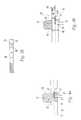
- FIG. 2 ashows a closed state of a valve of the invention
- FIG. 2 bshows an open state of the valve of FIG. 1 a
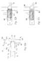
- FIG. 3 ashows a perspective cross sectional view of the valve of claim 1a
- FIG. 3 bshows a cross sectional view taken along section 3 b of FIG. 3 a;
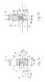
- FIG. 4 ashows a closed state of another valve of the invention
- FIG. 4 bshows an open state of the valve of FIG. 3 a
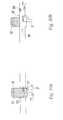
- FIG. 5 ashows a closed state of another valve of the invention
- FIG. 5 bshows an open state of the valve of FIG. 4 a
- FIG. 6 ashows a closed state of another valve of the invention
- FIG. 6 bshows an open state of the valve of FIG. 5 a
- FIG. 7 ashows a closed state of another valve of the invention
- FIG. 7 bshows an open state of the valve of FIG. 6 a
- FIG. 8 ashows a closed state of another valve of the invention
- FIG. 8 bshows an open state of the valve of FIG. 7 a
- FIG. 9 ashows a closed state of another valve of the invention.
- FIG. 9 bshows an open state of the valve of FIG. 8 a
- FIG. 10 ashows a closed state of another valve of the invention
- FIG. 10 bshows an open state of the valve of FIG. 9 a
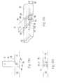
- FIG. 11 ashows a top view of another valve of the invention
- FIG. 11 bshows a side view of the valve of FIG. 10 a
- FIGS. 11 c and 11 dshow a perspective, cut-away view of the valve of FIG. 10 a;
- FIGS. 12 a - 12 cshow top views of a capillary assisted loading valve of the invention
- FIGS. 13 a - 13 dshow photolithigraphic masks suitable for fabricating a system according to the invention
- a microfluidic system 700 of the inventionis configured to perform analyses using minute amounts of material, such as samples and reagents, which can be transported among different regions of the system.
- the different regionsinclude, for example, chambers, channels and passages, as discussed below.
- An important feature of microfluidic system 700is the capability of regulating the passage of material between its different regions.
- system 700includes a valve 706 , which regulates the passage of material between a material introduction channel 702 and a chamber 704 .
- valve 706When valve 706 is open, material can be introduced into chamber 704 for processing, such as by concentrating, diluting, mixing, or reacting the material. Once a desired amount of material has been introduced, valve 706 can be closed to substantially prevent additional material from entering along channel 702 . Valve 706 operates as a multi-use valve, which can be toggled between the opened and closed states without loss of performance.
- FIGS. 2 a and 2 bAn embodiment of such a multi-use valve 50 is shown in FIGS. 2 a and 2 b .
- Valve 50regulates the passage of material between a first channel 52 and a second channel 54 .
- a valve passage 68connects the channels through the valve.
- TRS 56is retracted into a valve reservoir 55 to allow the passage of material from one channel to the other.
- a mass of temperature responsive material (TRS) 56substantially obstructs passage 68 .
- the closed valvesubstantially prevents the passage of material between channels 52 , 54 .
- the valve opening operationpreferably includes actuating a heat source 37 to heat TRS 56 thereby modifying a physical or chemical property thereof, such as by making TRS 56 softer.
- a cooler 36cools a gas 34 trapped in contact with an end 30 of TRS 56 .
- the resulting contraction of gas 32decreases the pressure acting upon end 30 and retracts the softened TRS 56 into reservoir 55 .
- gas 32is heated, which expands the gas thereby increasing the pressure acting upon end 30 and extending TRS 56 across passage 68 .
- valves of the present inventioninclude one or more elements configured to prevent leakage of a valve even when excess pressure acts upon the TRS obstructing the valve passage. Excess pressure occurs when the pressure present at one side of the valve is greater than the pressure present at the other side.
- excess upstream pressuremeans that the pressure acting upon the upstream side of the valve from the upstream channel is greater than the pressure acting upon the downstream side of the valve from the downstream channel.
- the at least one elementis a surface that is disposed in opposition to a material transport path, which is the path taken by material passing through the open valve. When the valve is closed the excess upstream pressure urges the TRS against the opposed surface rather than causing leakage through the obstructed passage.
- the TRS that obstructs passage 68extends from a reservoir 55 to a valve wall 72 .
- Reservoir 55includes an amount of TRS 57 that is offset from passage 68 so that TRS 57 does not obstruct the passage of material through the valve.
- Reservoir 55is preferably disposed on an opposite side of a passage central axis 63 from valve wall 72 .
- At least a first abutting portion 70 of TRS 56abuts wall 72 .
- the term “abuts”means that any remaining space between an abutting portion of a TRS and a wall of a closed valve is sufficiently small to substantially prevent the passage of material, such as a liquid, therethrough.
- the portion of a TRS that abuts a walltouches the wall, essentially eliminating the space therebetween.
- Wall 72includes a first opposed wall portion 74 , which is preferably disposed at an angle to passage central axis 51 .
- a second abutting portion 76 of TRS 56abuts first opposed wall portion 74 when valve 50 is closed.
- Second abutting portion 76 and first opposed wall portion 74substantially prevent passage of material through valve 50 even when the pressure acting upon an upstream portion 81 of TRS 56 exceeds the pressure applied to a downstream portion 78 of TRS 56 .
- Excess upstream pressureurges second abutting portion 76 against opposed wall surface 74 , thereby closing valve 50 more securely.
- excess upstream pressurecan distort the configuration of a TRS obstructing a valve passage, which could permit the undesirable leakage of material through the valve.
- First opposed wall portion 74is preferably integral with a wall projection 80 that extends into a path taken by material passing through passage 68 .
- a material transport path 63 from an upstream point 62 into passage 68is obstructed by opposed wall portion 74 .
- a material transport pathis the path taken by material, such as a sample and or reagent, in proceeding from an upstream location toward a downstream location.
- the terms upstream and downstreamrefer to the preferred direction of material transport through the valve. It should be understood, however, that a valve can be operated to permit or obstruct the passage of material from a downstream side of the valve to an upstream side.
- Projection 80includes a second opposed wall surface 86 and an outer wall 88 .
- a wall 90 of second channel 54is disposed on the opposite side of central axis 61 from outer wall 88 . Because projection 80 extends beyond wall 72 , a distance 82 between outer wall 88 and wall 90 is smaller than a corresponding distance 84 between opposed walls of first channel 52 at upstream point 62 . Downstream distance 82 is at least 10% smaller, preferably at least 20% smaller, and more preferably at least 30% smaller than upstream distance 84 .
- projection 80 and wall 90define a restriction, where a cross sectional area 67 of a downstream material transport path 59 is less than cross sectional area 66 of an upstream material transport path 58 .
- projection 80also offsets a central axis 61 of second channel 54 from a central axis 60 of first channel 52 .
- projection 80is shown as generally rectangular, alternative projections having other shapes such as triangular or shapes with arcuate surfaces can be used.
- Valve 50operates to open or close passage 68 upon a change of the temperature of TRS 56 from a first to a second, preferably higher temperature. Actuation of a heat source 37 , which is in thermal contact with at least a portion of TRS 56 and 57 , provides sufficient thermal energy to change a physical or chemical characteristic of the heated portion of TRS. Preferably, the change in characteristic is a softening or a decrease in size that is sufficient to allow a motion of at least TRS 56 with respect to passage 68 . Valve 50 can be repeatedly switched between the opened and closed states without a significant loss of material 56 or capacity to prevent passage of material through the valve when closed.
- a temperature responsive materialrefers to a material that exhibits a change in at least one physical or chemical characteristic upon a transition from a first temperature to a second, different temperature.
- the mass of TRS that obstructs a valve passagecan be an essentially solid mass or an agglomeration of smaller particles that cooperate to obstruct the passage.
- TRS'sinclude, but are not limited to solder, wax, polymers, plastics, and combinations thereof.
- the characteristicis at least one of a decreased hardness and a decreased size.
- the TRSmelts upon a transition from a first temperature to a second, higher temperature.
- the TRS that meltsis a meltable substance that may be, for example, a wax (for example, an olefin) or a eutectic alloy (for example, a solder).
- the first and second temperaturesare preferably insufficiently high to damage materials, such as nearby electronic components or the device substrate.
- the second temperatureis preferably from 40° to 90° C. and most preferably from 50° to 70° C.
- the TRSdoes not disperse upon melting but merely softens.
- the TRSis a substance having a coefficient of thermal expansion that is different from the material forming the obstructed passage. Heating or cooling the passage and TRS causes the TRS to expand or contract relative to the passage. In the contracted state, the TRS can be actuated to move in or out of the channel, as described below.
- passagerefers to the region within a valve that is obstructed by a mass of TRS with the valve fully closed.
- the passageis the region through which material, such as a liquid, can pass through the valve from an upstream location to a downstream location.
- surfaces of the valve reservoirare not part of the passage because material in the passage is preferably excluded from passing into the reservoir.
- the “mass of TRS”refers to an amount of TRS sufficient to substantially obstruct the valve passage, thereby substantially preventing the passage of material through the valve. Substantially preventing the passage of material prevents the passage of an amount of material that would undesirably deplete the volume of a micro-droplet located upstream from the valve.
- substantially preventing the passage of materialprevents upstream material from adversely impacting micro-droplets located downstream from the valve.
- concentration of or pH of the downstream dropletremains essentially unchanged when upstream material is blocked by a closed valve.
- a closed valvecompletely prevents the passage of any liquid or particle adjacent the valve.
- valve 50an open state of valve 50 is shown in which TRS 56 has been essentially fully retracted into reservoir 55 to open passage 68 , thereby permitting passage of material through valve 50 from at least one of the first and second channels to the other.
- essentially fully retractedit is meant that essentially all of TRS 56 , which had obstructed passage 68 , is retracted into reservoir 55 rather than remaining in passage 68 or dispersing downstream of valve 50 .
- TRS 56Upon fully retracting TRS 56 , not more than about 10%, preferably not more than about 5%, and most preferably not more than about 2% of TRS 56 is left behind in passage 68 and dispersed downstream of valve 50 .
- the opening motionis preferably driven by decreasing the pressure upon end 30 of TRS 57 relative to the pressure acting upon TRS abutting portion 70 .
- the decreased pressurepreferably occurs upon the contraction of a fluid, such as gas 32 present in actuating portion 34 of reservoir 55 .
- the contraction of gas 32can be obtained by cooling the gas to decrease the gas temperature and volume.
- Gas 32is preferably cooled by actuating a cooler, such as a Peltier cooler in thermal contact with gas 32 .
- the cooleris preferably integral with the substrate comprising valve 50 and with heat source 36 . It should be understood, however, that the cooler can be located in a separate device that receives the substrate during operation.
- valve 50permits passage of material being transported from first channel 52 to second channel 54 .
- An opening distance 92 from abutting TRS portion 70 to wall 72is sufficiently large to allow material to be passed through passage at a desired material transport rate.
- opening distance 92is preferably at least as great as distance 82 of second channel 54 . It should be understood, however, that valve 50 can be operated in a partially open state, in which opening distance 92 is less than distance 82 .
- Valve 50operates to close passage 68 when a closing motion of TRS 56 moves TRS abutting portion 70 across passage 68 to abut wall 72 .
- the closing motionis preferably driven by pressure acting upon end 30 .
- the pressureis obtained by the expansion of a fluid, such as gas 32 .
- the expansion of gas 32is preferably obtained by increasing the temperature of the gas by actuating a heat source 36 in thermal contact with gas 32 .
- Heat source 36is preferably integral with the substrate comprising valve 50 . It should be understood, however, that the heat source can be located in an auxiliary device that accommodates the substrate during operation.
- valve 50 ′having a different opening operation is shown.
- the opening of valve 50 ′is actuated by changing the temperature of at least a portion of a mass of TRS 56 ′, which obstructs passage 68 .
- Actuation of a heat source 37 ′, which is in thermal contact with TRS 56 ′provides the thermal energy to raise TRS 56 ′ from a first temperature to a second, preferably higher temperature.
- the second temperatureis preferably sufficient to allow TRS 56 ′ to melt or disperse, thereby opening passage 68 .
- the portion of TRS 56 ′ that is raised to the second temperatureis sufficient to open passage 68 .
- a valve of type 50 ′is a gate-type valve as distinguished from valve 50 in which material retracts into a reservoir to open the valve.
- the entry of TRS 56 ′ into the downstream channelis preferably assisted by the application of excess upstream pressure against TRS 56 ′.
- the upstream pressurecan be provided using a source of gas pressure in fluid communication with the upstream channel.
- TRS 56 ′enters the downstream channel upon opening passage 68
- gate type valves, such as valve 50 ′, of the inventioncan be returned to the closed state once opened.
- additional TRScan be made to flow from the reservoir associated with the gate valve into the passage by heating at least the associated reservoir.
- Heat source 37 ′is preferably configured to heat a downstream length 45 of second channel 54 ′ to a temperature sufficient to prevent dispersing or melting TRS from obstructing second channel 54 ′.
- Length 45 ′is at least 50% and preferably at least 75% as long as a length of passage 68 obstructed by TRS 56 ′.
- Heat source 37 ′heats the walls of the adjacent portion of the downstream channel to a temperature sufficient to at least often and preferably melt or disperse TRS 56 .
- a portion of dispersed or melted TRS 56 ′can be deposited within downstream channels in small volumes TRS 59 ′ that have a size insufficient to obstruct a downstream channel.
- TRS 56 ′can also be formed of a material that opens passage 68 ′ without melting.
- the obstructing TRSis formed of an agglomeration of particles. Upon a transition to a higher temperature, the agglomerated particles disperse downstream thereby opening the valve.
- Valve 50 ′includes a reservoir 55 ′, which allows TRS 56 ′ and 57 ′ to be introduced into passage 68 ′ and reservoir 55 ′, respectively.
- the passage and reservoirare heated, such as by an external heat source, and TRS is introduced into an access port 40 ′. Once the TRS has just obstructed the passage, the external heat source is removed. TRS 56 ′ then obstructs passage 68 ′ of valve 50 ′, which operates similarly to valve 50 by preventing leakage in response to upstream pressure.
- the temperature of TRS 57 ′ in reservoir 55 ′is preferably not raised by an amount sufficient to disperse or melt TRS 57 ′.
- substantially all of TRS 57 ′remains essentially stationary in reservoir 55 ′ so that access port 40 is not brought into fluid communication with passage 68 ′.
- the lower temperature of TRS 57 ′can be maintained by limiting the duration of heat applied to TRS 56 ′ and by increasing the distance of access port 40 from passage 68 .
- a valve 150 having two downstream abutting portionsis shown in a closed state.
- a mass of temperature responsive material 156obstructs material transport through a passage 168 between first and second channels 152 , 154 .
- a first abutting portion 170 of TRS 156abuts a wall 172 of closed valve 150 .
- Wall 172includes a first opposed wall portion 174 , which is disposed at an angle to central axis 160 and material transport path 158 .
- Thermally responsive substance 156includes a second abutting portion 176 disposed to abut first opposed wall portion 174 when valve 150 is closed.
- a third abutting portion 200 of TRS 156abuts an opposed wall portion 202 of valve 150 .
- Opposed wall portion 202is disposed on an opposite side of central axis 161 from opposed wall portion 174 , preferably adjacent a reservoir of TRS 155 .
- Abutting portions 176 , 200 and wall surfaces 174 , 202are configured and disposed to prevent undesirable leakage through valve 150 when the pressure acting upon an upstream portion 181 of TRS 156 exceeds the pressure acting upon a downstream portion 178 .
- the excess upstream pressurepreferably urges abutting portions 176 and 200 against opposed wall portions 174 and 202 , respectively, thereby closing valve 150 more securely.
- the presence of two downstream opposed wallsdecreases the tendency of TRS 56 to distort in response to upstream pressure.
- First opposed wall surface 174is preferably integral with a first wall projection 180 that extends into a material transport path 156 of first channel 52 .
- Projection 180includes a second opposed wall portion 186 and an outer wall surface 188 .
- Opposed wall portion 202is integral with a second wall projection 204 that also extends into material transport path 156 .
- Projection 204includes a second opposed wall portion 206 and an outer wall portion 208 .
- a distance 182 between outer wall portions 188 , and 90is preferably smaller than a corresponding distance 184 between opposed walls of first channel 152 at a point 162 upstream from valve 150 .
- Distance 182is at least 10% smaller, preferably at least 20% smaller, and more preferably at least 30% smaller than upstream distance 184 .
- opposed wall portions 174 , 202 or projections 180 , 204define a restriction therebetween.
- the restrictionhas a smaller cross sectional area than a cross sectional area at upstream point 162 .
- projections 180 and 204are shown as generally rectangular, projections having other shapes such as triangular or shapes with arcuate surfaces can be used.
- valve 150an open state of valve 150 is shown in which TRS 156 has been essentially fully retracted into reservoir 155 to open passage 168 , thereby permitting passage of material through valve 150 from at least one of the first and second channels to the other.
- an opening distance 192 from abutting TRS portion 170 to wall 172is preferably at least as great distance 182 of second channel 54 .
- valve 50can be operated in a partially open state, in which opening distance 192 is less than distance 182 .
- an open state of valve 150can be repositioned repeatedly between the opened and closed states without a significant loss of material 156 or capacity to prevent transport of material when closed.
- valve 150 ′seen in FIGS. 6 a and 6 b operates similarly to valve 150 in the closed state.
- valve 150 ′operates similarly to valve 50 ′ in that a mass of TRS 156 ′ obstructing passage 68 disperses or melts, thereby opening passage 68 .
- the dispersal or meltingpreferably occurs upon actuation of a heat source 37 in thermal contact with TRS 156 ′.
- a valve 250includes a projection 280 having first and second opposed wall portions 274 , 286 that cooperate to prevent leakage in response to both upstream and downstream pressure.
- a mass of temperature responsive material 256obstructs a valve passage 268 , thereby at least substantially preventing the transport of material in either direction between a first channel 252 and a second channel 254 .
- Projection 280is preferably centered relative to a dimension 287 of TRS 256 that is substantially aligned with a material transport path 258 .
- projection 280is shown as being substantially square, a projection having any shape, such as rectangular, triangular, or arcuate can be used.
- a first abutting portion 276 of TRS 256abuts first opposed wall portion 274 and a second abutting portion 277 of TRS 256 abuts second opposed wall portion 286 .
- First and second abutting portions 276 , and respective opposed wall portions 274 , 286substantially prevent passage of material through valve 50 when excess pressure is applied to either a first side 276 or a second side 278 of TRS 256 .
- excess upstream pressure acting upon second side 278urges second abutting portion 277 against opposed wall portion 286 , thereby closing valve 250 more securely.
- Valve 250responds similarly when excess upstream pressure acts upon first side 281 .
- valve 250operates as a two-way valve to prevent leakage in response to excess pressure from either of two flow directions.
- at least a third abutting portion 274abuts a valve wall 270 , which is preferably substantially aligned with a central axis 260 of first channel 252 .
- a length of the thermally responsive substance that is aligned with a material transport pathis greater than at least one of a width of the passage obstructed by the thermally responsive substance and a width of an upstream channel.
- the term lengthrefers to a distance along a material transport path, which is preferably aligned with a central axis of a channel or passage.
- the term widthrefers to the larger dimension of a channel or passage that is opposed to a material transport path or central axis therethrough.
- a dimension or length 287 of TRS 256is greater than a width 289 of passage 268 and a width 284 of first channel 252 .
- a dimension or width 291 of reservoir 255is preferably at least as large as length 287 .
- Dimension 287 of TRS 256is at least 15%, preferably at least 25%, and more preferably at least 30% greater than width 284 of first channel 252 .
- valve 250an open state of valve 250 is shown in which TRS 256 has been essentially fully retracted into reservoir 255 to open passage 268 , thereby permitting passage of material through valve 250 . Because TRS 256 is essentially fully retracted into reservoir 255 rather than being dispersed in a downstream direction or left in passage 268 , abutting portions 276 , 277 can still exhibit an impression of projection 280 .
- valve 250can be operated in a partially open state, in which third abutting portion 272 is intermediately disposed between a fully closed position abutting wall 270 and a fully opened position substantially aligned with a first channel wall 273 .
- an open state of valve 250can be repeatedly repositioned between the opened and closed states without a significant loss of material 256 or capacity to prevent transport of material when closed.
- a gate valve 250 ′seen in FIGS. 8 a and 8 b operates to close the valve similarly to valve 250 .
- valve 250 ′operates similarly to valve 50 ′ in that a mass of TRS 256 ′ obstructing passage 268 ′ disperses or melts and enters a downstream channel, thereby opening the valve.
- the dispersal or meltingpreferably occurs upon actuation of a heat source 37 in thermal contact with TRS 256 .
- a valve 350includes an opposed wall portion 374 that does not extend into a material transport path 360 of a first channel 352 .
- a mass of thermally responsive substance 356obstructs a passage 368 .
- a first abutting portion 376 of TRS 356abuts first opposed wall portion 374 . Excess upstream pressure present at a first surface 376 of TRS 356 urges first abutting portion 376 against first opposed wall portion 374 , thereby closing valve 350 more securely.
- Valve 350preferably includes a second opposed wall portion 386 that also does not extend into material transport path 360 .
- First and second opposed wall portions 374 , 386oppose one another so that valve 350 operates as a two-way valve.
- excess upstream pressure present at a second surface 378 of TRS 356urges a second abutting portion 377 of TRS 356 against second opposed wall portion 386 .
- valve 350 TRS 356is retracted into reservoir 355 , thereby opening passage 368 to the passage of material.
- a gate valve 350 ′seen in FIGS. 10 a and 10 b operates close similarly to valve 350 .
- valve 350 ′operates similarly to valve 50 ′ in that a mass of TRS 356 ′ obstructing passage 368 disperses or melts, thereby opening the valve.
- the dispersal or meltingpreferably occurs upon actuation of a heat source 37 in thermal contact with TRS 356 ′.
- substantially all of TRS 356 ′enters second channel 354 , downstream from valve 350 ′.
- Valve 450defines a passage 468 between first and second channels 452 , 454 .
- a temperature responsive substancewhich, for clarity, is not shown in FIGS. 11 a - 11 c , operates to open and close the valve, as discussed above.
- the opening of valve 450comprises a retraction motion of TRS 456 into a reservoir 455 .
- the opening of passage 468comprises a dispersing or melting of TRS 456 , which enters at least one downstream channel, thereby opening passage 468 .
- Loading surface 500is configured to limit the amount of TRS that enters channels 452 , 454 when TRS 456 is introduced into passage 468 .
- An opening 515 between passage 468 and first channel 452defines a cross sectional area 516 , which is at least 40% smaller, preferably at least about 50% smaller, than an adjacent cross sectional area 518 within first channel 452 .
- an opening 520 between passage 468 and second channel 454preferably has a smaller cross sectional area than an adjacent cross sectional area within second channel 454 .
- the reduced cross section of the passage openingsis preferably achieved by reducing a height of the passage.
- a height of a channel or passagerefers to the smallest dimension of the channel or passage.
- Distance 502is at least about 40% preferably at least about 50%, and more preferably at least about 65% less than distances 506 , 507 .
- a reservoir 455 and passage 468are heated sufficiently to allow motion of the TRS therein.
- TRSis introduced through access port 40 .
- Capillary actiondraws TRS into passage 468 .
- TRS in passage 468encounters resistance, such as that caused by the surface tension of the TRS resisting the expansion of the surface area upon moving from the lower cross-sectional area opening into first and second channels 452 , 454 .
- loading surface 500allows the introduction of an amount of TRS that is sufficient to obstruct the passage of a valve but insufficient to enter adjacent channels 452 and 454 .
- Valve 450can include at least one opposed surface, such as opposed wall portion as described above, to prevent leakage in response to excess pressure present in either of channels when the valve is closed.
- a valve 1001has a loading surface 1000 that extends from a passage 1004 into a reservoir 1002 .
- Valve 1001includes first and second channels 1006 , 1008 and a protrusion 1010 .
- Protrusion 1010extends for a width w 1 into passage 1004 so that a width w 3 of the passage is less than a width w 2 of first and second channels 1006 , 1008 .
- Width w 3is preferably from about 25% to about 75%, such as about 50% of width w 2 .
- Width w 3is preferably from about 25% to about 75%, such as about 50%, of a width w 4 of reservoir channel.
- the widths of first and second channels 1006 , 1008are preferably, but not necessarily, the same. However, if one of the first or second channels is made wider, its height would have to be correspondingly reduced.
- the width w 4 of the reservoircan be wider or narrower than the width w 2 of the first and second channels.
- Loading surface 1000reduces a height of passage 1004 and of a loading portion 1012 of reservoir channel 1002 .
- the height of passage 1004 and loading portion 1012is from about 25% to about 75%, such as about 50% of a height of first and second channels 1006 , 1008 and of a height of a distal portion 1014 of reservoir 1002 .
- an amount of TRSis introduced through a hole 1015 until a leading edge of the TRS reaches edge 1016 of loading surface 1000 .
- Heat sources 1020 and 1021are used to raise the temperature of reservoir 1002 and passage 1004 to a temperature sufficient to allow the TRS to flow.
- capillary actiondraws the TRS into loading portion 1012 and passage 1004 .
- surface tensionsubstantially prevents the TRS from entering first and second channels 1006 , 1008 .
- the valveis in the closed state to substantially prevent the passage of material between first and second channels 1006 , 1008 .
- the temperature of the TRS obstructing passage 1004is raised to a temperature sufficient to allow at least a portion of the TRS obstructing the passage 1004 to disperse or melt and enter at least one of first and second channels 1006 , 1008 .
- Pressuresuch as air or liquid pressure, from one of the first and second channels preferably displaces the TRS obstructing the channel once the temperature has been raised.
- the temperature of the TRS in the reservoiris preferably not raised by an amount sufficient to disperse or melt the TRS.
- Valve 1001can be returned to the closed state by heating TRS present in reservoir 1002 . Capillary action will draw the TRS into passage 1004 , as discussed above.
- Valve 1001can be opened and closed repeatedly as long as an amount of TRS remains in the distal portion of reservoir 1002 .
- the amount of TRS present in the distal portion of the reservoiris preferably greater than the amount of TRS that was dispersed upon opening the passage.
- the dispersed TRSenters one of the first or second channels.
- the amount of TRS in the distal portion of the reservoiris preferably at least slightly greater than the amount of TRS in the loading portion to ensure that the TRS will fully re-close passage 1004 .
- the mean radius of curvature (MRC) of a distal end of TRS within the distal portion 1014 of reservoir 1002is preferably greater than the MRC of a proximal end of TRS within the loading portion 1000 or within the passage 1004 .
- distalit is meant that portion of the TRS that is spaced apart from passage 1004
- proximalit is meant that portion of the TRS that is adjacent or within passage 1004 .
- the contact angle of the TRS with walls of the loading portionis substantially constant.
- Valve 1001can also include an opposing surface, such as that shown in FIGS. 11 a - 11 d , to assist in preventing the passage of material when the valve is in the closed state.
- Valve 1001can also be configured as a non-capillary assisted loading valve in which loading surface 1000 is absent.
- a constant channel widthis not required.
- channels of varying widthmay be used.
- the tendency of a TRS to move in a given directionis governed by the ratio between the mean radius of curvature of the front of the drop and the mean radius of curvature of the back of the drop. These curvatures are based on the contact angle of the fluid with the material and the dimensions of the channel.
- Chamber 704defined in substrate 701 , is preferably configured to perform at least one chemical or physical process using material therein.
- Materialincludes samples and reagents such as, for example, fluids, particles, such as cells, DNA, viruses, and particle containing fluids.
- chamber 704can be configured to mix a sample with a reagent to facilitate a chemical reaction.
- chamber 704can be configured to concentrate or dilute a sample.
- Other processes, such as PCR amplification, filtering, and the likeare also possible. It should be understood that chamber 704 can have the same dimensions as a channel.
- An outlet channel 710is provided as an outlet to remove excess sample or reagent materials from chamber 704 .
- a valve 712is operated in the open state to allow material to exit chamber 704 via channel 710 .
- channel 710includes a flow through member, such as a filter, to allow only selected material to exit chamber 704 via channel 710 .
- a valve 714prevents material within chamber 704 from entering a downstream channel 716 .
- a valve 718prevents material within chamber 704 from entering an on-board pressure source 720 , which is preferably a thermally actuated type, as discussed above.
- Pressure source 720preferably provides a sufficient gas pressure and gas volume to drive material present in chamber 704 into downstream channel 716 .
- valve 712Upon completion of any process carried out within chamber 704 , valve 712 is closed to prevent any material from exiting chamber 704 via channel 704 .
- pressure source 720 and heat sources associated with valves 714 and 718are actuated thereby opening both valves. Material is transported through a passage of valve 714 into downstream channel 716 for analysis or further processing.
- Downstream processing chamberspreferably include chambers to lyse cells, such as bacterial cells.
- Example bacteriainclude Group B streptococcus and bacteria associated with bacterial menengitis. Cells can be lysed to release nucleic acids therein, as known in the art by contacting the cells with a lysing agent, such as a surfactant and/or buffer.
- the systemis preferably provided with a reservoir of buffer connected by a channel to the lysing chamber.
- a second downstream processing chamberis preferably configured to perform a PCR reaction upon nucleic acids released from the lysed cells.
- the PCR chamberis joined by channels configured to introduce reagents, such as enzymes and buffers suitable to facilitate the amplification of the nucleic acids.
- System 700preferably includes contacts 720 , which provide electrical or optical communication with various on-board system elements, such as valves, heaters, procession chambers, sensors to detect the state of valves, and the like.
- Preferred computer control systems and methods for operating thermally actuated valvesare disclosed in U.S. patent application Ser. No. 09/819,105 filed Mar. 28, 2001, which is hereby incorporated herein in its entirety.
- Substrate defining elementssuch as channels and valves can be formed of any suitable material, such as silicon, quartz, glass, and polymeric materials.
- the substratecan be homogenous or formed of one or more elements bonded together, such as a silicon substrate having a bonded quartz cover.
- the cover and substrateare micromachined with system features, including the valves, passages, channels, heaters.
- Micromachiningincludes fabrication techniques, such as photolithography followed by chemical etching, laser ablation, direct imprinting, stereo lithography, and injection molding.
- a preferred microfluidic systemis fabricated by injection molding of a substrate comprising one or more cyclic olefins.
- valve 714includes upstream and downstream channels 1030 , 1031 and a reservoir 1032 .
- TRS associated with valve 714is not shown.
- Valve 714includes a protrusion 1034 and an opposing surface 1033 associated with a passage 1035 .
- Photolithographic masks suitable for using in micromachining a system of the inventionare shown.
- Photolithographyprovides one approach for fabricating a microfluidic system.
- An example photolithographic processbegins by deposit a metal, such as at least one of chrome and gold, onto a substrate. Techniques such as vapor deposition or electron beam sputtering can be used to deposit the metal layer.
- a preferred substrate for fabricating channel, passage, and valve elementsis a 500 micron thick Dow Coming 7740 Pyrex wafer. The wafer is coated with a layer of photo-resist, such as by spin coating.
- a photolithographic mask 950 indicative of the elements to be microfabricatedis used as a pattern. The substrate is exposed to a light source with the mask in place and the resist is developed. Patterning removes the resist from areas of the substrate that will be etched.
- An etchantsuch as an acid, is used to remove the metal layer protecting regions of the substrate where the resist had been removed.
- the resulting unprotected areas of the substrateare etched, preferably to a depth of about 50 microns, using an etchant, such as buffered hydrofluoric acid. Once etching is complete, the remaining resist and metal is removed. Holes are drilled to allow the introduction of thermally responsive material, as described above.
- Heater elementsare preferably fabricated upon a second substrate, such as a 500 micron thick quartz wafer.
- a metalsuch as a 2500 angstrom thick layer of aluminum, is deposited onto the substrate, which is then coated with a layer of resist.
- the coated substrateis masked using a mask 952 and patterned as described above. Aluminum is removed, such as by etching, from the areas of the substrate where the resist has been removed. Subsequently, the remaining resist is stripped away.
- a low temperature oxide layeris deposited onto the substrate.
- a layer of metalsuch as a chrome-gold layer, is deposited over the oxide layer.
- the metal layeris coated with resist and patterned with a third mask 954 , which preferably defines the pattern that will become the recess, which receives a flow through member.
- the chrome gold layeris etched to form the recess.
- the low temperature oxideis etched to a depth of about 100 microns using and etchant such as an aqueous hydrofluoric/nitric acid mixture.
- etchantsuch as an aqueous hydrofluoric/nitric acid mixture.
- the resist and chrome gold layeris removed.
- a the oxide layeris coated with a layer of resist and patterned with a fourth mask 956 , which preferably defines the pattern for electrical contacts to the system.
- An etchantsuch as buffered hydrofluoric acid is used to etch through the exposed oxide. Holes are drilled through the second substrate directly opposite to where the channel will be.
- the first and second substrateare bonded together, as understood in the art.
- Stereolithographic approaches for fabricating systems of the inventionincrease the efficiency of prototyping and in manufacturing microfluidic devices.
- Hi-resolution (about 0.004′′ spot size) stereolithographyallows channel designs to be rapidly formed into a working system.
- the time savings, cost savings, and flexibility of the stereolithographyallows us to test more designs more quickly and cheaply than ever before.
- the epoxy-based resins used by the conventional stereolithography devicesare not well suited to some uses in microfluidic devices. They cannot withstand high temperatures, they absorb fluids (slowly), they are fluorescent under an excitation source, and they are not optically clear. These properties are not obstacles to basic fluidic tests, but for full tests of device functionality and for manufacture, a material with more robust properties and a method for forming it is needed.
- a material line from Ticona (a subsidiary of Celanese A. G.) called Topas, such as Topas 5013can be used.
- the Topas materialis formed by an injection molding process.
- the mold halves for this processare generated by stereolithography. This reduces the lead-time usually necessary to create molds. For short run parts, this method works well. In the long run, steel molds are preferably created. Injection molded parts represent a dramatic cost savings over parts that are created in glass and quartz by a photolithographic process.
Landscapes
- Engineering & Computer Science (AREA)
- General Engineering & Computer Science (AREA)
- Chemical & Material Sciences (AREA)
- Mechanical Engineering (AREA)
- Dispersion Chemistry (AREA)
- Health & Medical Sciences (AREA)
- General Health & Medical Sciences (AREA)
- Physics & Mathematics (AREA)
- Analytical Chemistry (AREA)
- Clinical Laboratory Science (AREA)
- Chemical Kinetics & Catalysis (AREA)
- General Physics & Mathematics (AREA)
- Immunology (AREA)
- Pathology (AREA)
- Hematology (AREA)
- Life Sciences & Earth Sciences (AREA)
- Biochemistry (AREA)
- Theoretical Computer Science (AREA)
- Fluid Mechanics (AREA)
- Temperature-Responsive Valves (AREA)
- Micromachines (AREA)
- Details Of Valves (AREA)
- Safety Valves (AREA)
Abstract
Description
Claims (34)
Priority Applications (14)
| Application Number | Priority Date | Filing Date | Title |
|---|---|---|---|
| US09/953,921US6575188B2 (en) | 2001-07-26 | 2001-09-18 | Methods and systems for fluid control in microfluidic devices |
| US10/014,520US7270786B2 (en) | 2001-03-28 | 2001-12-14 | Methods and systems for processing microfluidic samples of particle containing fluids |
| US10/014,519US7192557B2 (en) | 2001-03-28 | 2001-12-14 | Methods and systems for releasing intracellular material from cells within microfluidic samples of fluids |
| US10/075,371US7323140B2 (en) | 2001-03-28 | 2002-02-15 | Moving microdroplets in a microfluidic device |
| JP2003517479AJP4519462B2 (en) | 2001-07-26 | 2002-03-27 | Fluid control method and system in microfluidic device |
| EP20020723636EP1425528B1 (en) | 2001-07-26 | 2002-03-27 | Methods and systems for fluid control in microfluidics devices |
| PCT/US2002/009441WO2003012325A1 (en) | 2001-07-26 | 2002-03-27 | Methods and systems for fluid control in microfluidics devices |
| AT02723636TATE530825T1 (en) | 2001-07-26 | 2002-03-27 | METHOD AND SYSTEMS FOR FLUID CONTROL IN MICROFLUID DEVICES |
| US11/929,971US8273308B2 (en) | 2001-03-28 | 2007-10-30 | Moving microdroplets in a microfluidic device |
| JP2008223484AJP4892528B2 (en) | 2001-07-26 | 2008-09-01 | Valves used in microfluidic devices |
| JP2010068070AJP5129286B2 (en) | 2001-07-26 | 2010-03-24 | Fluid control method and system in microfluidic device |
| JP2012090981AJP5536819B2 (en) | 2001-07-26 | 2012-04-12 | Fluid control method and system in microfluidic device |
| US13/620,452US8703069B2 (en) | 2001-03-28 | 2012-09-14 | Moving microdroplets in a microfluidic device |
| US14/255,861US20140227710A1 (en) | 2001-03-28 | 2014-04-17 | Moving microdroplets in a microfluidic device |
Applications Claiming Priority (2)
| Application Number | Priority Date | Filing Date | Title |
|---|---|---|---|
| US30763801P | 2001-07-26 | 2001-07-26 | |
| US09/953,921US6575188B2 (en) | 2001-07-26 | 2001-09-18 | Methods and systems for fluid control in microfluidic devices |
Related Parent Applications (1)
| Application Number | Title | Priority Date | Filing Date |
|---|---|---|---|
| US09/819,105Continuation-In-PartUS7010391B2 (en) | 2001-03-28 | 2001-03-28 | Methods and systems for control of microfluidic devices |
Related Child Applications (3)
| Application Number | Title | Priority Date | Filing Date |
|---|---|---|---|
| US10/014,519Continuation-In-PartUS7192557B2 (en) | 2001-03-28 | 2001-12-14 | Methods and systems for releasing intracellular material from cells within microfluidic samples of fluids |
| US10/014,520Continuation-In-PartUS7270786B2 (en) | 2001-03-28 | 2001-12-14 | Methods and systems for processing microfluidic samples of particle containing fluids |
| US10/075,371Continuation-In-PartUS7323140B2 (en) | 2001-03-28 | 2002-02-15 | Moving microdroplets in a microfluidic device |
Publications (2)
| Publication Number | Publication Date |
|---|---|
| US20030019522A1 US20030019522A1 (en) | 2003-01-30 |
| US6575188B2true US6575188B2 (en) | 2003-06-10 |
Family
ID=26975846
Family Applications (1)
| Application Number | Title | Priority Date | Filing Date |
|---|---|---|---|
| US09/953,921Expired - LifetimeUS6575188B2 (en) | 2001-03-28 | 2001-09-18 | Methods and systems for fluid control in microfluidic devices |
Country Status (5)
| Country | Link |
|---|---|
| US (1) | US6575188B2 (en) |
| EP (1) | EP1425528B1 (en) |
| JP (4) | JP4519462B2 (en) |
| AT (1) | ATE530825T1 (en) |
| WO (1) | WO2003012325A1 (en) |
Cited By (112)
| Publication number | Priority date | Publication date | Assignee | Title |
|---|---|---|---|---|
| US20040040302A1 (en)* | 2002-08-30 | 2004-03-04 | Winkler Daniel S. | One-shot electro-pneumatic actuator |
| US20040115830A1 (en)* | 2002-09-25 | 2004-06-17 | Igor Touzov | Components for nano-scale Reactor |
| US20040157220A1 (en)* | 2003-02-10 | 2004-08-12 | Purnima Kurnool | Methods and apparatus for sample tracking |
| US20040179975A1 (en)* | 2002-07-26 | 2004-09-16 | Cox David M. | Microfluidic device including displaceable material trap, and system |
| US20040195539A1 (en)* | 2002-07-26 | 2004-10-07 | Mead Dennis E. | Valve assembly for microfluidic devices, and method for opening and closing same |
| US20040219732A1 (en)* | 2002-11-04 | 2004-11-04 | The Regents Of The University Of Michigan | Thermal micro-valves for micro-integrated devices |
| US20040242982A1 (en)* | 2001-09-11 | 2004-12-02 | Tetsuya Sakata | Measuring instrument, installation body, and density measurer |
| US20050056799A1 (en)* | 2003-09-11 | 2005-03-17 | Malone Steven J. | Valves having a thermostatic actuator controlled by a peltier device |
| US20050152808A1 (en)* | 2001-09-12 | 2005-07-14 | Karthik Ganesan | Microfluidic devices having a reduced number of input and output connections |
| US20050247356A1 (en)* | 2004-05-10 | 2005-11-10 | Welle Richard P | Phase-change valve apparatuses |
| US20050284527A1 (en)* | 2004-06-24 | 2005-12-29 | The Aerospace Corporation | Electro-hydraulic devices |
| US20050284526A1 (en)* | 2004-06-24 | 2005-12-29 | The Aerospace Corporation | Electro-hydraulic valve apparatuses |
| US20060018795A1 (en)* | 2004-07-23 | 2006-01-26 | General Electric Company | Fabrication methods and multifunctional substrate materials for chemical and biological analysis in microfluidic systems |
| US20060070697A1 (en)* | 2004-09-23 | 2006-04-06 | Ingersoll Machine Tools, Inc. | Method and apparatus for directing resin-impregnated tape |
| US20060219308A1 (en)* | 2005-04-02 | 2006-10-05 | Oh Kwang-Wook | Microvalve having magnetic wax plug and flux control method using magnetic wax |
| US20060245933A1 (en)* | 2005-05-02 | 2006-11-02 | General Electric Company | Valve and pump for microfluidic systems and methods for fabrication |
| US20060280029A1 (en)* | 2005-06-13 | 2006-12-14 | President And Fellows Of Harvard College | Microfluidic mixer |
| KR100738113B1 (en)* | 2006-05-10 | 2007-07-12 | 삼성전자주식회사 | Phase transfer valve and its manufacturing method |
| US20070227592A1 (en)* | 2004-05-10 | 2007-10-04 | E2V Biosensors Limited | Valve for a Microfluidic Device |
| US20070231216A1 (en)* | 2006-04-04 | 2007-10-04 | Samsung Electronics Co., Ltd | Valve unit and apparatus having the same |
| US20070286774A1 (en)* | 2004-12-09 | 2007-12-13 | Claus Barholm-Hansen | Micro fluidic devices and methods for producing same |
| US20080094448A1 (en)* | 2004-12-17 | 2008-04-24 | Brother Kogyo Kabushiki Kaisha | Valve And Actuator Employing Capillary Electrowetting Phenomenon |
| US20080163945A1 (en)* | 2006-12-20 | 2008-07-10 | Applera Corporation | Devices and Methods for Flow Control in Microfluidic Structures |
| US20080173354A1 (en)* | 2006-11-10 | 2008-07-24 | Canon Kabushiki Kaisha | Micro-machined temperature dependent one-shot valve and process for production thereof |
| US20080182301A1 (en)* | 2006-03-24 | 2008-07-31 | Kalyan Handique | Microfluidic system for amplifying and detecting polynucleotides in parallel |
| US20080226502A1 (en)* | 2005-07-07 | 2008-09-18 | Jacques Jonsmann | Microfluidic Methods and Support Instruments |
| US20080295891A1 (en)* | 2007-05-31 | 2008-12-04 | Canon Kabushiki Kaisha | Valve and production method thereof |
| US20080314465A1 (en)* | 2007-06-21 | 2008-12-25 | Samsung Electronics Co., Ltd. | Microfluidic valve, method of manufacturing the same, and microfluidic device comprising the microfluidic valve |
| US20090281343A1 (en)* | 2008-05-08 | 2009-11-12 | University Of Florida Research Foundation, Inc. | Method for transferring n-atoms from metal complexes to organic and inorganic substrates |
| US20090317793A1 (en)* | 2007-01-10 | 2009-12-24 | Scandinavian Micro Biodevices Aps | Microfluidic device and a microfluidic system and a method of performing a test |
| WO2010012281A1 (en) | 2008-07-29 | 2010-02-04 | Jacques Jonsmann | A microfluidic device |
| US20100089529A1 (en)* | 2005-01-12 | 2010-04-15 | Inverness Medical Switzerland Gmbh | Microfluidic devices and production methods therefor |
| US20100101660A1 (en)* | 2007-02-27 | 2010-04-29 | Konica Minolta Holdings, Inc. | Channel switching system |
| US7721762B2 (en) | 2004-06-24 | 2010-05-25 | The Aerospace Corporation | Fast acting valve apparatuses |
| USRE41780E1 (en) | 2003-03-14 | 2010-09-28 | Lawrence Livermore National Security, Llc | Chemical amplification based on fluid partitioning in an immiscible liquid |
| US20100252124A1 (en)* | 2007-11-22 | 2010-10-07 | Koninklijke Philips Electronics N.V. | Valve for a microfluidic system |
| US7829025B2 (en) | 2001-03-28 | 2010-11-09 | Venture Lending & Leasing Iv, Inc. | Systems and methods for thermal actuation of microfluidic devices |
| EP2279789A2 (en) | 2009-07-30 | 2011-02-02 | Karlsruher Institut für Technologie | Device for controlling the throughput of fluids through microfluid channels, method for operating same and application of same |
| US20110048563A1 (en)* | 2008-02-26 | 2011-03-03 | Ulvac, Inc. | Switch valve |
| US20110126918A1 (en)* | 2006-04-04 | 2011-06-02 | Samsung Electronics Co., Ltd. | Valve unit and reaction apparatus having the same |
| US20110217712A1 (en)* | 2010-03-02 | 2011-09-08 | Quantalife, Inc. | Emulsion chemistry for encapsulated droplets |
| US8088616B2 (en) | 2006-03-24 | 2012-01-03 | Handylab, Inc. | Heater unit for microfluidic diagnostic system |
| EP2402089A1 (en) | 2003-07-31 | 2012-01-04 | Handylab, Inc. | Processing particle-containing samples |
| US8105783B2 (en) | 2007-07-13 | 2012-01-31 | Handylab, Inc. | Microfluidic cartridge |
| US8133671B2 (en) | 2007-07-13 | 2012-03-13 | Handylab, Inc. | Integrated apparatus for performing nucleic acid extraction and diagnostic testing on multiple biological samples |
| US8182763B2 (en) | 2007-07-13 | 2012-05-22 | Handylab, Inc. | Rack for sample tubes and reagent holders |
| US8216530B2 (en) | 2007-07-13 | 2012-07-10 | Handylab, Inc. | Reagent tube |
| USD665095S1 (en) | 2008-07-11 | 2012-08-07 | Handylab, Inc. | Reagent holder |
| US8273308B2 (en) | 2001-03-28 | 2012-09-25 | Handylab, Inc. | Moving microdroplets in a microfluidic device |
| US8287820B2 (en) | 2007-07-13 | 2012-10-16 | Handylab, Inc. | Automated pipetting apparatus having a combined liquid pump and pipette head system |
| USD669191S1 (en) | 2008-07-14 | 2012-10-16 | Handylab, Inc. | Microfluidic cartridge |
| US8324372B2 (en) | 2007-07-13 | 2012-12-04 | Handylab, Inc. | Polynucleotide capture materials, and methods of using same |
| US8440149B2 (en) | 2001-02-14 | 2013-05-14 | Handylab, Inc. | Heat-reduction methods and systems related to microfluidic devices |
| US8470586B2 (en) | 2004-05-03 | 2013-06-25 | Handylab, Inc. | Processing polynucleotide-containing samples |
| CN101050417B (en)* | 2006-04-04 | 2013-07-10 | 三星电子株式会社 | Valve unit and apparatus having the same |
| US20130263940A1 (en)* | 2012-04-05 | 2013-10-10 | Thinxxs Microtechnology Ag | Flow cell with a temperature-control chamber |
| USD692162S1 (en) | 2011-09-30 | 2013-10-22 | Becton, Dickinson And Company | Single piece reagent holder |
| US8617905B2 (en) | 1995-09-15 | 2013-12-31 | The Regents Of The University Of Michigan | Thermal microvalves |
| US8633015B2 (en) | 2008-09-23 | 2014-01-21 | Bio-Rad Laboratories, Inc. | Flow-based thermocycling system with thermoelectric cooler |
| US8642353B2 (en) | 2004-05-10 | 2014-02-04 | The Aerospace Corporation | Microfluidic device for inducing separations by freezing and associated method |
| US8663920B2 (en) | 2011-07-29 | 2014-03-04 | Bio-Rad Laboratories, Inc. | Library characterization by digital assay |
| US8709787B2 (en) | 2006-11-14 | 2014-04-29 | Handylab, Inc. | Microfluidic cartridge and method of using same |
| US8709762B2 (en) | 2010-03-02 | 2014-04-29 | Bio-Rad Laboratories, Inc. | System for hot-start amplification via a multiple emulsion |
| US8730479B2 (en) | 2010-03-25 | 2014-05-20 | Bio-Rad Laboratories, Inc. | Detection system for droplet-based assays |
| US8768517B2 (en) | 2001-03-28 | 2014-07-01 | Handylab, Inc. | Methods and systems for control of microfluidic devices |
| US8852862B2 (en) | 2004-05-03 | 2014-10-07 | Handylab, Inc. | Method for processing polynucleotide-containing samples |
| US8883490B2 (en) | 2006-03-24 | 2014-11-11 | Handylab, Inc. | Fluorescence detector for microfluidic diagnostic system |
| US8895311B1 (en) | 2001-03-28 | 2014-11-25 | Handylab, Inc. | Methods and systems for control of general purpose microfluidic devices |
| US8951939B2 (en) | 2011-07-12 | 2015-02-10 | Bio-Rad Laboratories, Inc. | Digital assays with multiplexed detection of two or more targets in the same optical channel |
| US20150083228A1 (en)* | 2012-03-23 | 2015-03-26 | Karlsruher Institut für Technologie | Bistable actuator, actuator arrangement, method for actuaton and use |
| US9040288B2 (en) | 2006-03-24 | 2015-05-26 | Handylab, Inc. | Integrated system for processing microfluidic samples, and method of using the same |
| US9089844B2 (en) | 2010-11-01 | 2015-07-28 | Bio-Rad Laboratories, Inc. | System for forming emulsions |
| US9126160B2 (en) | 2008-09-23 | 2015-09-08 | Bio-Rad Laboratories, Inc. | System for forming an array of emulsions |
| US20150252794A1 (en)* | 2014-03-06 | 2015-09-10 | Airbus Ds Gmbh | Single-Actuation Valve Arrangement for Aerospace Component, and Aerospace Component |
| US9132394B2 (en) | 2008-09-23 | 2015-09-15 | Bio-Rad Laboratories, Inc. | System for detection of spaced droplets |
| US9186677B2 (en) | 2007-07-13 | 2015-11-17 | Handylab, Inc. | Integrated apparatus for performing nucleic acid extraction and diagnostic testing on multiple biological samples |
| US9194861B2 (en) | 2009-09-02 | 2015-11-24 | Bio-Rad Laboratories, Inc. | Method of mixing fluids by coalescence of multiple emulsions |
| US9222128B2 (en) | 2011-03-18 | 2015-12-29 | Bio-Rad Laboratories, Inc. | Multiplexed digital assays with combinatorial use of signals |
| US9222954B2 (en) | 2011-09-30 | 2015-12-29 | Becton, Dickinson And Company | Unitized reagent strip |
| US9222623B2 (en) | 2013-03-15 | 2015-12-29 | Genmark Diagnostics, Inc. | Devices and methods for manipulating deformable fluid vessels |
| US9347059B2 (en) | 2011-04-25 | 2016-05-24 | Bio-Rad Laboratories, Inc. | Methods and compositions for nucleic acid analysis |
| US9393560B2 (en) | 2010-03-25 | 2016-07-19 | Bio-Rad Laboratories, Inc. | Droplet transport system for detection |
| US9399215B2 (en) | 2012-04-13 | 2016-07-26 | Bio-Rad Laboratories, Inc. | Sample holder with a well having a wicking promoter |
| US9415392B2 (en) | 2009-03-24 | 2016-08-16 | The University Of Chicago | Slip chip device and methods |
| US9417190B2 (en) | 2008-09-23 | 2016-08-16 | Bio-Rad Laboratories, Inc. | Calibrations and controls for droplet-based assays |
| US9447461B2 (en) | 2009-03-24 | 2016-09-20 | California Institute Of Technology | Analysis devices, kits, and related methods for digital quantification of nucleic acids and other analytes |
| US9464319B2 (en) | 2009-03-24 | 2016-10-11 | California Institute Of Technology | Multivolume devices, kits and related methods for quantification of nucleic acids and other analytes |
| US9492797B2 (en) | 2008-09-23 | 2016-11-15 | Bio-Rad Laboratories, Inc. | System for detection of spaced droplets |
| US9500664B2 (en) | 2010-03-25 | 2016-11-22 | Bio-Rad Laboratories, Inc. | Droplet generation for droplet-based assays |
| US9498778B2 (en) | 2014-11-11 | 2016-11-22 | Genmark Diagnostics, Inc. | Instrument for processing cartridge for performing assays in a closed sample preparation and reaction system |
| US9598722B2 (en) | 2014-11-11 | 2017-03-21 | Genmark Diagnostics, Inc. | Cartridge for performing assays in a closed sample preparation and reaction system |
| US9618139B2 (en) | 2007-07-13 | 2017-04-11 | Handylab, Inc. | Integrated heater and magnetic separator |
| USD787087S1 (en) | 2008-07-14 | 2017-05-16 | Handylab, Inc. | Housing |
| US9764322B2 (en) | 2008-09-23 | 2017-09-19 | Bio-Rad Laboratories, Inc. | System for generating droplets with pressure monitoring |
| US9765389B2 (en) | 2011-04-15 | 2017-09-19 | Becton, Dickinson And Company | Scanning real-time microfluidic thermocycler and methods for synchronized thermocycling and scanning optical detection |
| US9957553B2 (en) | 2012-10-24 | 2018-05-01 | Genmark Diagnostics, Inc. | Integrated multiplex target analysis |
| US10005080B2 (en) | 2014-11-11 | 2018-06-26 | Genmark Diagnostics, Inc. | Instrument and cartridge for performing assays in a closed sample preparation and reaction system employing electrowetting fluid manipulation |
| US10196700B2 (en) | 2009-03-24 | 2019-02-05 | University Of Chicago | Multivolume devices, kits and related methods for quantification and detection of nucleic acids and other analytes |
| KR20190074733A (en) | 2017-12-20 | 2019-06-28 | 주식회사 씨디젠 | Lab-on-a Disc apparatus using black thermoplastic resin valve and non-contact temperature sensor |
| US10495656B2 (en) | 2012-10-24 | 2019-12-03 | Genmark Diagnostics, Inc. | Integrated multiplex target analysis |
| US10512910B2 (en) | 2008-09-23 | 2019-12-24 | Bio-Rad Laboratories, Inc. | Droplet-based analysis method |
| USD881409S1 (en) | 2013-10-24 | 2020-04-14 | Genmark Diagnostics, Inc. | Biochip cartridge |
| US10822644B2 (en) | 2012-02-03 | 2020-11-03 | Becton, Dickinson And Company | External files for distribution of molecular diagnostic tests and determination of compatibility between tests |
| US10864520B2 (en) | 2015-07-22 | 2020-12-15 | The University Of North Carolina At Chapel Hill | Fluidic devices with freeze-thaw valves with ice-nucleating agents and related methods of operation and analysis |
| US10900066B2 (en) | 2006-03-24 | 2021-01-26 | Handylab, Inc. | Microfluidic system for amplifying and detecting polynucleotides in parallel |
| US11130128B2 (en) | 2008-09-23 | 2021-09-28 | Bio-Rad Laboratories, Inc. | Detection method for a target nucleic acid |
| US11453906B2 (en) | 2011-11-04 | 2022-09-27 | Handylab, Inc. | Multiplexed diagnostic detection apparatus and methods |
| US11806718B2 (en) | 2006-03-24 | 2023-11-07 | Handylab, Inc. | Fluorescence detector for microfluidic diagnostic system |
| US12090480B2 (en) | 2008-09-23 | 2024-09-17 | Bio-Rad Laboratories, Inc. | Partition-based method of analysis |
| US12097495B2 (en) | 2011-02-18 | 2024-09-24 | Bio-Rad Laboratories, Inc. | Methods and compositions for detecting genetic material |
| US12162008B2 (en) | 2008-09-23 | 2024-12-10 | Bio-Rad Laboratories, Inc. | Partition-based method of analysis |
| US12168231B2 (en) | 2008-09-23 | 2024-12-17 | Bio-Rad Laboratories, Inc. | Method of analysis |
Families Citing this family (32)
| Publication number | Priority date | Publication date | Assignee | Title |
|---|---|---|---|---|
| US7338760B2 (en)* | 2001-10-26 | 2008-03-04 | Ntu Ventures Private Limited | Sample preparation integrated chip |
| US20030138819A1 (en)* | 2001-10-26 | 2003-07-24 | Haiqing Gong | Method for detecting disease |
| FR2856046B1 (en)* | 2003-06-16 | 2005-07-29 | Biomerieux Sa | FLUIDIC MICROVANNE WITH OPENING BY ELECTRICAL CONTROL |
| EP1824601B1 (en)* | 2004-10-18 | 2016-12-28 | Life Technologies Corporation | A device including a dissolvable structure for flow control |
| JP2006300145A (en)* | 2005-04-18 | 2006-11-02 | Erumu:Kk | Micro valve and micro chip having the same |
| FR2888912B1 (en) | 2005-07-25 | 2007-08-24 | Commissariat Energie Atomique | METHOD FOR CONTROLLING COMMUNICATION BETWEEN TWO ZONES BY ELECTROWRINKING, DEVICE COMPRISING ISOLABLE ZONES AND OTHERS AND METHOD FOR PRODUCING SUCH DEVICE |
| EP1920883B1 (en)* | 2005-08-05 | 2013-05-22 | Yuzo Mori | Electron beam assisted eem method |
| JP2009511059A (en)* | 2005-10-11 | 2009-03-19 | ハンディーラブ インコーポレイテッド | Polynucleotide sample preparation device |
| WO2007048410A1 (en)* | 2005-10-24 | 2007-05-03 | Danfoss A/S | A flow system and a micro fluidic system comprising a flow system |
| US8464760B2 (en) | 2006-08-16 | 2013-06-18 | Samsung Electronic Co., Ltd. | Valve unit, reaction apparatus with the same, and method of forming valve in channel |
| KR100851980B1 (en)* | 2006-09-05 | 2008-08-12 | 삼성전자주식회사 | Centrifugal force-based microfluidic device having a thermally active unit, a microfluidic system including the same, and a method of driving the microfluidic system |
| KR100846501B1 (en)* | 2006-11-09 | 2008-07-17 | 삼성전자주식회사 | Valve unit and fluid treatment device having same |
| EP1977830A1 (en)* | 2007-03-30 | 2008-10-08 | Roche Diagnostics GmbH | Micro-fluidic temperature driven valve |
| US20100009351A1 (en)* | 2008-07-11 | 2010-01-14 | Handylab, Inc. | Polynucleotide Capture Materials, and Method of Using Same |
| KR101390717B1 (en)* | 2008-09-02 | 2014-04-30 | 삼성전자주식회사 | Microfluidic device and method of loading sample thereto |
| FR2945097B1 (en)* | 2009-04-30 | 2011-06-03 | Commissariat Energie Atomique | MICROFLUIDIC VALVE FOR SINGLE USE. |
| JP5819290B2 (en)* | 2009-06-03 | 2015-11-24 | コーニンクレッカ フィリップス エヌ ヴェKoninklijke Philips N.V. | Valve with material with variable degree of permeability |
| RU2500944C1 (en)* | 2012-05-15 | 2013-12-10 | Федеральное государственное бюджетное образовательное учреждение высшего профессионального образования "Московский авиационный институт (национальный исследовательский университет)" (МАИ) | Shutoff valve with independent sealing system |
| US10545161B2 (en) | 2013-03-11 | 2020-01-28 | Cue Health Inc. | Systems and methods for detection and quantification of analytes |
| US9623409B2 (en) | 2013-03-11 | 2017-04-18 | Cue Inc. | Cartridges, kits, and methods for enhanced mixing for detection and quantification of analytes |
| KR102557135B1 (en) | 2013-03-11 | 2023-07-19 | 큐 헬스 인코퍼레이티드 | Systems and methods for detection and quantification of analytes |
| US9617921B2 (en)* | 2013-07-31 | 2017-04-11 | General Electric Company | Thermal actuator including fluid with high temperature stability |
| USD745423S1 (en) | 2014-05-12 | 2015-12-15 | Cue Inc. | Automated analyzer test cartridge and sample collection device for analyte detection |
| US11241687B2 (en)* | 2014-11-26 | 2022-02-08 | Imec Vzw | Compact glass-based fluid analysis device and method to fabricate |
| EP3223946B1 (en)* | 2014-11-26 | 2019-01-02 | IMEC vzw | Fluid analysis device and method for fluid analysis |
| NL2014801B1 (en)* | 2015-05-13 | 2017-01-27 | Berkin Bv | Fluid flow device, comprising a valve unit, as well as method of manufacturing the same. |
| AU2016296589B2 (en) | 2015-07-17 | 2021-11-18 | Cue Health Inc. | Systems and methods for enhanced detection and quantification of analytes |
| WO2018064775A1 (en)* | 2016-10-07 | 2018-04-12 | Xinyu Liu | A microfluidic analytical platform for autonomous immunoassays |
| WO2018140540A1 (en) | 2017-01-25 | 2018-08-02 | Cue Health Inc. | Systems and methods for enhanced detection and quantification of analytes |
| GB201703233D0 (en)* | 2017-02-28 | 2017-04-12 | Ge Healthcare Bio Sciences Ab | A modular bio-processing unit and a bio-processing system employing plural units |
| CN108855260B (en)* | 2018-06-16 | 2021-04-02 | 南京大学 | A kind of paraffin microvalve molding and its packaging method |
| US10738903B2 (en)* | 2018-08-29 | 2020-08-11 | International Business Machines Corporation | Microfluidic relief valve |
Citations (127)
| Publication number | Priority date | Publication date | Assignee | Title |
|---|---|---|---|---|
| US1616419A (en)* | 1925-04-03 | 1927-02-01 | Everlasting Valve Co | Automatic shut-off device for gas in case of fire |
| US1773401A (en)* | 1927-10-20 | 1930-08-19 | Luther D Lovekin | Fusible-plug water release |
| US3528449A (en)* | 1968-02-27 | 1970-09-15 | Trw Inc | Fluid flow control apparatus |
| US4139005A (en)* | 1977-09-01 | 1979-02-13 | Dickey Gilbert C | Safety release pipe cap |
| US4612959A (en)* | 1985-05-07 | 1986-09-23 | Mobil Oil Corporation | Valveless shut-off and transfer device |
| US4654127A (en) | 1984-04-11 | 1987-03-31 | Sentech Medical Corporation | Self-calibrating single-use sensing device for clinical chemistry and method of use |
| US4673657A (en) | 1983-08-26 | 1987-06-16 | The Regents Of The University Of California | Multiple assay card and system |
| US4946562A (en) | 1987-01-29 | 1990-08-07 | Medtest Systems, Inc. | Apparatus and methods for sensing fluid components |
| US4949742A (en)* | 1989-04-26 | 1990-08-21 | Spectra-Physics, Inc. | Temperature operated gas valve |
| US4963498A (en) | 1985-08-05 | 1990-10-16 | Biotrack | Capillary flow device |
| US4989626A (en)* | 1988-11-11 | 1991-02-05 | Hitachi, Ltd. | Apparatus for and method of controlling the opening and closing of channel for liquid |
| US5001417A (en) | 1987-06-01 | 1991-03-19 | Abbott Laboratories | Apparatus for measuring electrolytes utilizing optical signals related to the concentration of the electrolytes |
| US5004583A (en) | 1987-01-29 | 1991-04-02 | Medtest Systems, Inc. | Universal sensor cartridge for use with a universal analyzer for sensing components in a multicomponent fluid |
| US5053199A (en) | 1989-02-21 | 1991-10-01 | Boehringer Mannheim Corporation | Electronically readable information carrier |
| US5061336A (en) | 1989-05-01 | 1991-10-29 | Soane Technologies, Inc. | Gel casting method and apparatus |
| US5064618A (en) | 1987-08-29 | 1991-11-12 | Thorn Emi Plc | Sensor arrangements |
| US5071531A (en) | 1989-05-01 | 1991-12-10 | Soane Technologies, Inc. | Casting of gradient gels |
| US5126002A (en) | 1989-09-29 | 1992-06-30 | Glory Kogyo Kabushiki Kaisha | Leaf paper bundling apparatus |
| US5126022A (en) | 1990-02-28 | 1992-06-30 | Soane Tecnologies, Inc. | Method and device for moving molecules by the application of a plurality of electrical fields |
| US5135627A (en) | 1990-10-15 | 1992-08-04 | Soane Technologies, Inc. | Mosaic microcolumns, slabs, and separation media for electrophoresis and chromatography |
| US5135872A (en) | 1989-04-28 | 1992-08-04 | Sangstat Medical Corporation | Matrix controlled method of delayed fluid delivery for assays |
| US5147606A (en) | 1990-08-06 | 1992-09-15 | Miles Inc. | Self-metering fluid analysis device |
| US5208163A (en) | 1990-08-06 | 1993-05-04 | Miles Inc. | Self-metering fluid analysis device |
| US5250263A (en) | 1990-11-01 | 1993-10-05 | Ciba-Geigy Corporation | Apparatus for processing or preparing liquid samples for chemical analysis |
| US5282950A (en) | 1991-07-15 | 1994-02-01 | Boehringer Mannheim Gmbh | Electrochemical analysis system |
| US5296375A (en) | 1992-05-01 | 1994-03-22 | Trustees Of The University Of Pennsylvania | Mesoscale sperm handling devices |
| US5304477A (en) | 1991-07-08 | 1994-04-19 | Fuji Oil Company, Limited | Process for producing hard fats using 1,3-specific lipase and mixture of palmitic, lauric and behemic acids |
| US5304487A (en) | 1992-05-01 | 1994-04-19 | Trustees Of The University Of Pennsylvania | Fluid handling in mesoscale analytical devices |
| US5316727A (en) | 1989-09-08 | 1994-05-31 | Terumo Kabushiki Kaisha | Measuring apparatus |
| US5339486A (en) | 1993-03-10 | 1994-08-23 | Persic Jr William V | Golf ball cleaner |
| US5372946A (en) | 1992-12-10 | 1994-12-13 | International Technidyne Corporation | Blood coagulation time test apparatus and method |
| US5374395A (en) | 1993-10-14 | 1994-12-20 | Amoco Corporation | Diagnostics instrument |
| US5411708A (en) | 1991-08-06 | 1995-05-02 | Moscetta; Pompeo | Apparatus for the determination of analytes in liquid samples |
| US5486335A (en) | 1992-05-01 | 1996-01-23 | Trustees Of The University Of Pennsylvania | Analysis based on flow restriction |
| US5498392A (en) | 1992-05-01 | 1996-03-12 | Trustees Of The University Of Pennsylvania | Mesoscale polynucleotide amplification device and method |
| US5503803A (en) | 1988-03-28 | 1996-04-02 | Conception Technologies, Inc. | Miniaturized biological assembly |
| US5519635A (en) | 1993-09-20 | 1996-05-21 | Hitachi Ltd. | Apparatus for chemical analysis with detachable analytical units |
| US5559432A (en) | 1992-02-27 | 1996-09-24 | Logue; Delmar L. | Joystick generating a polar coordinates signal utilizing a rotating magnetic field within a hollow toroid core |
| US5565171A (en) | 1993-05-28 | 1996-10-15 | Governors Of The University Of Alberta | Continuous biochemical reactor for analysis of sub-picomole quantities of complex organic molecules |
| US5569364A (en) | 1992-11-05 | 1996-10-29 | Soane Biosciences, Inc. | Separation media for electrophoresis |
| US5580523A (en) | 1994-04-01 | 1996-12-03 | Bard; Allen J. | Integrated chemical synthesizers |
| US5585069A (en) | 1994-11-10 | 1996-12-17 | David Sarnoff Research Center, Inc. | Partitioned microelectronic and fluidic device array for clinical diagnostics and chemical synthesis |
| US5585089A (en) | 1988-12-28 | 1996-12-17 | Protein Design Labs, Inc. | Humanized immunoglobulins |
| US5587128A (en) | 1992-05-01 | 1996-12-24 | The Trustees Of The University Of Pennsylvania | Mesoscale polynucleotide amplification devices |
| US5589136A (en) | 1995-06-20 | 1996-12-31 | Regents Of The University Of California | Silicon-based sleeve devices for chemical reactions |
| US5599432A (en) | 1993-11-11 | 1997-02-04 | Ciba-Geigy Corporation | Device and a method for the electrophoretic separation of fluid substance mixtures |
| US5599503A (en) | 1990-11-26 | 1997-02-04 | Ciba-Geigy Corporation | Detector cell |
| US5603351A (en) | 1995-06-07 | 1997-02-18 | David Sarnoff Research Center, Inc. | Method and system for inhibiting cross-contamination in fluids of combinatorial chemistry device |
| US5605662A (en) | 1993-11-01 | 1997-02-25 | Nanogen, Inc. | Active programmable electronic devices for molecular biological analysis and diagnostics |
| US5628890A (en) | 1995-09-27 | 1997-05-13 | Medisense, Inc. | Electrochemical sensor |
| US5631337A (en) | 1996-01-19 | 1997-05-20 | Soane Bioscience | Thermoreversible hydrogels comprising linear copolymers and their use in electrophoresis |
| US5632957A (en) | 1993-11-01 | 1997-05-27 | Nanogen | Molecular biological diagnostic systems including electrodes |
| US5632876A (en) | 1995-06-06 | 1997-05-27 | David Sarnoff Research Center, Inc. | Apparatus and methods for controlling fluid flow in microchannels |
| US5637469A (en) | 1992-05-01 | 1997-06-10 | Trustees Of The University Of Pennsylvania | Methods and apparatus for the detection of an analyte utilizing mesoscale flow systems |
| US5639423A (en) | 1992-08-31 | 1997-06-17 | The Regents Of The University Of Calfornia | Microfabricated reactor |
| US5652149A (en) | 1992-12-08 | 1997-07-29 | Westinghouse Electric Corporation | Mixing apparatus & method for an optical agglutination assay device |
| US5681529A (en) | 1994-08-25 | 1997-10-28 | Nihon Medi-Physics Co., Ltd. | Biological fluid analyzing device |
| US5683657A (en) | 1994-03-24 | 1997-11-04 | Gamera Bioscience, Corp. | DNA meltometer |
| US5699157A (en) | 1996-07-16 | 1997-12-16 | Caliper Technologies Corp. | Fourier detection of species migrating in a microchannel |
| US5726026A (en) | 1992-05-01 | 1998-03-10 | Trustees Of The University Of Pennsylvania | Mesoscale sample preparation device and systems for determination and processing of analytes |
| US5731212A (en) | 1994-12-20 | 1998-03-24 | International Technidyne Corporation | Test apparatus and method for testing cuvette accommodated samples |
| US5747666A (en) | 1997-03-26 | 1998-05-05 | Willis; John P. | Point-of-care analyzer module |
| US5750015A (en) | 1990-02-28 | 1998-05-12 | Soane Biosciences | Method and device for moving molecules by the application of a plurality of electrical fields |
| US5763262A (en) | 1986-09-18 | 1998-06-09 | Quidel Corporation | Immunodiagnostic device |
| US5770029A (en) | 1996-07-30 | 1998-06-23 | Soane Biosciences | Integrated electrophoretic microdevices |
| US5772966A (en) | 1997-01-24 | 1998-06-30 | Maracas; George N. | Assay dispensing apparatus |
| US5779868A (en) | 1996-06-28 | 1998-07-14 | Caliper Technologies Corporation | Electropipettor and compensation means for electrophoretic bias |
| US5787032A (en) | 1991-11-07 | 1998-07-28 | Nanogen | Deoxyribonucleic acid(DNA) optical storage using non-radiative energy transfer between a donor group, an acceptor group and a quencher group |
| US5788814A (en) | 1996-04-09 | 1998-08-04 | David Sarnoff Research Center | Chucks and methods for positioning multiple objects on a substrate |
| US5800690A (en) | 1996-07-03 | 1998-09-01 | Caliper Technologies Corporation | Variable control of electroosmotic and/or electrophoretic forces within a fluid-containing structure via electrical forces |
| US5827481A (en) | 1997-07-31 | 1998-10-27 | Hewlett-Packard Company | Cartridge system for effecting sample acquisition and introduction |
| US5842106A (en) | 1995-06-06 | 1998-11-24 | Sarnoff Corporation | Method of producing micro-electrical conduits |
| US5842787A (en) | 1997-10-09 | 1998-12-01 | Caliper Technologies Corporation | Microfluidic systems incorporating varied channel dimensions |
| US5846396A (en) | 1994-11-10 | 1998-12-08 | Sarnoff Corporation | Liquid distribution system |
| US5849489A (en) | 1991-11-07 | 1998-12-15 | Nanogen, Inc. | Hybridization of polynucleotides conjugated with chromophores and fluorophores to generate donor-to-donor energy transfer system |
| US5849486A (en) | 1993-11-01 | 1998-12-15 | Nanogen, Inc. | Methods for hybridization analysis utilizing electrically controlled hybridization |
| US5849598A (en) | 1996-03-15 | 1998-12-15 | Washington University | Method for transferring micro quantities of liquid samples to discrete locations |
| US5856174A (en) | 1995-06-29 | 1999-01-05 | Affymetrix, Inc. | Integrated nucleic acid diagnostic device |
| US5858188A (en) | 1990-02-28 | 1999-01-12 | Aclara Biosciences, Inc. | Acrylic microchannels and their use in electrophoretic applications |
| US5863801A (en) | 1996-06-14 | 1999-01-26 | Sarnoff Corporation | Automated nucleic acid isolation |
| US5863502A (en) | 1996-01-24 | 1999-01-26 | Sarnoff Corporation | Parallel reaction cassette and associated devices |
| US5869004A (en) | 1997-06-09 | 1999-02-09 | Caliper Technologies Corp. | Methods and apparatus for in situ concentration and/or dilution of materials in microfluidic systems |
| US5872010A (en) | 1995-07-21 | 1999-02-16 | Northeastern University | Microscale fluid handling system |
| US5874046A (en) | 1996-10-30 | 1999-02-23 | Raytheon Company | Biological warfare agent sensor system employing ruthenium-terminated oligonucleotides complementary to target live agent DNA sequences |
| US5876675A (en) | 1997-08-05 | 1999-03-02 | Caliper Technologies Corp. | Microfluidic devices and systems |
| US5882465A (en) | 1997-06-18 | 1999-03-16 | Caliper Technologies Corp. | Method of manufacturing microfluidic devices |
| US5883211A (en) | 1996-01-19 | 1999-03-16 | Aclara Biosciences, Inc. | Thermoreversible hydrogels comprising linear copolymers and their use in electrophoresis |
| US5885470A (en) | 1997-04-14 | 1999-03-23 | Caliper Technologies Corporation | Controlled fluid transport in microfabricated polymeric substrates |
| US5885432A (en) | 1992-11-05 | 1999-03-23 | Soane Biosciences | Un-crosslinked polymeric media for electrophoresis |
| US5895762A (en) | 1996-03-25 | 1999-04-20 | Diasys Corporation | Apparatus and method for handling fluid samples of body materials |
| US5900130A (en) | 1997-06-18 | 1999-05-04 | Alcara Biosciences, Inc. | Method for sample injection in microchannel device |
| US5912134A (en) | 1994-09-02 | 1999-06-15 | Biometric Imaging, Inc. | Disposable cartridge and method for an assay of a biological sample |
| US5912124A (en) | 1996-06-14 | 1999-06-15 | Sarnoff Corporation | Padlock probe detection |
| US5916522A (en) | 1997-08-07 | 1999-06-29 | Careside, Inc. | Electrochemical analytical cartridge |
| US5916776A (en) | 1997-08-27 | 1999-06-29 | Sarnoff Corporation | Amplification method for a polynucleotide |
| US5919711A (en) | 1997-08-07 | 1999-07-06 | Careside, Inc. | Analytical cartridge |
| US5927547A (en) | 1996-05-31 | 1999-07-27 | Packard Instrument Company | System for dispensing microvolume quantities of liquids |
| US5932799A (en) | 1997-07-21 | 1999-08-03 | Ysi Incorporated | Microfluidic analyzer module |
| US5935401A (en) | 1996-09-18 | 1999-08-10 | Aclara Biosciences | Surface modified electrophoretic chambers |
| US5939291A (en) | 1996-06-14 | 1999-08-17 | Sarnoff Corporation | Microfluidic method for nucleic acid amplification |
| US5942443A (en) | 1996-06-28 | 1999-08-24 | Caliper Technologies Corporation | High throughput screening assay systems in microscale fluidic devices |
| US5948227A (en) | 1997-12-17 | 1999-09-07 | Caliper Technologies Corp. | Methods and systems for performing electrophoretic molecular separations |
| US5955028A (en) | 1996-08-02 | 1999-09-21 | Caliper Technologies Corp. | Analytical system and method |
| US5958203A (en) | 1996-06-28 | 1999-09-28 | Caliper Technologies Corportion | Electropipettor and compensation means for electrophoretic bias |
| US5959291A (en) | 1997-06-27 | 1999-09-28 | Caliper Technologies Corporation | Method and apparatus for measuring low power signals |
| US5958694A (en) | 1997-10-16 | 1999-09-28 | Caliper Technologies Corp. | Apparatus and methods for sequencing nucleic acids in microfluidic systems |
| US5964997A (en) | 1997-03-21 | 1999-10-12 | Sarnoff Corporation | Balanced asymmetric electronic pulse patterns for operating electrode-based pumps |
| US5965886A (en) | 1996-03-27 | 1999-10-12 | Sarnoff Corporation | Infrared imager using room temperature capacitance sensor |
| US5964995A (en) | 1997-04-04 | 1999-10-12 | Caliper Technologies Corp. | Methods and systems for enhanced fluid transport |
| US5965410A (en) | 1997-09-02 | 1999-10-12 | Caliper Technologies Corp. | Electrical current for controlling fluid parameters in microchannels |
| US5976336A (en) | 1997-04-25 | 1999-11-02 | Caliper Technologies Corp. | Microfluidic devices incorporating improved channel geometries |
| US5980719A (en) | 1997-05-13 | 1999-11-09 | Sarnoff Corporation | Electrohydrodynamic receptor |
| US5989402A (en) | 1997-08-29 | 1999-11-23 | Caliper Technologies Corp. | Controller/detector interfaces for microfluidic systems |
| US5992820A (en) | 1997-11-19 | 1999-11-30 | Sarnoff Corporation | Flow control in microfluidics devices by controlled bubble formation |
| US5993750A (en) | 1997-04-11 | 1999-11-30 | Eastman Kodak Company | Integrated ceramic micro-chemical plant |
| US5993611A (en) | 1997-09-24 | 1999-11-30 | Sarnoff Corporation | Capacitive denaturation of nucleic acid |
| US5997708A (en) | 1997-04-30 | 1999-12-07 | Hewlett-Packard Company | Multilayer integrated assembly having specialized intermediary substrate |
| US6001231A (en) | 1997-07-15 | 1999-12-14 | Caliper Technologies Corp. | Methods and systems for monitoring and controlling fluid flow rates in microfluidic systems |
| US6001307A (en) | 1996-04-26 | 1999-12-14 | Kyoto Daiichi Kagaku Co., Ltd. | Device for analyzing a sample |
| US6012902A (en) | 1997-09-25 | 2000-01-11 | Caliper Technologies Corp. | Micropump |
| US6048734A (en) | 1995-09-15 | 2000-04-11 | The Regents Of The University Of Michigan | Thermal microvalves in a fluid flow method |
| US6054034A (en) | 1990-02-28 | 2000-04-25 | Aclara Biosciences, Inc. | Acrylic microchannels and their use in electrophoretic applications |
| US6057149A (en) | 1995-09-15 | 2000-05-02 | The University Of Michigan | Microscale devices and reactions in microscale devices |
| US6130098A (en) | 1995-09-15 | 2000-10-10 | The Regents Of The University Of Michigan | Moving microdroplets |
| US6168948B1 (en) | 1995-06-29 | 2001-01-02 | Affymetrix, Inc. | Miniaturized genetic analysis systems and methods |
| US6287254B1 (en) | 1999-11-02 | 2001-09-11 | W. Jean Dodds | Animal health diagnosis |
| US6306273B1 (en) | 1999-04-13 | 2001-10-23 | Aclara Biosciences, Inc. | Methods and compositions for conducting processes in microfluidic devices |
Family Cites Families (14)
| Publication number | Priority date | Publication date | Assignee | Title |
|---|---|---|---|---|
| JPH01154460A (en)* | 1987-12-10 | 1989-06-16 | Matsushita Electric Ind Co Ltd | Manufacturing method for cadmium electrodes for batteries |
| FI86229C (en)* | 1989-04-10 | 1992-07-27 | Niilo Kaartinen | FOERFARANDE FOER FORMNING AV ETT UPPVAERMBART OCH NEDKYLBART ELEMENT VID ETT SYSTEM BEHANDLANDE SMAO VAETSKEMAENGDER SAMT ETT MEDELST FOERFARANDET FRAMSTAELLT ELEMENT. |
| JPH07332219A (en)* | 1994-06-02 | 1995-12-22 | Zenichi Ogita | Temperature-sensitive response actuator, temperature-response valve operated by the actuator, and temperature-sensitive switch |
| US6001229A (en)* | 1994-08-01 | 1999-12-14 | Lockheed Martin Energy Systems, Inc. | Apparatus and method for performing microfluidic manipulations for chemical analysis |
| DE19749011A1 (en)* | 1996-11-19 | 1998-05-20 | Lang Volker | Micro=valve for one time use has opening closed by plug mounted on resistance plate |
| KR100351531B1 (en)* | 1997-04-25 | 2002-09-11 | 캘리퍼 테크놀로지스 코포레이션 | Microfludic devices incorporating improved channel geometries |
| AU746098B2 (en)* | 1997-09-02 | 2002-04-18 | Caliper Life Sciences, Inc. | Microfluidic system with electrofluidic and electrothermal controls |
| US6084734A (en)* | 1997-12-08 | 2000-07-04 | Maxtor Corporation | Data recovery using targeted ECC correction |
| US6274089B1 (en)* | 1998-06-08 | 2001-08-14 | Caliper Technologies Corp. | Microfluidic devices, systems and methods for performing integrated reactions and separations |
| US6375901B1 (en)* | 1998-06-29 | 2002-04-23 | Agilent Technologies, Inc. | Chemico-mechanical microvalve and devices comprising the same |
| US6261431B1 (en)* | 1998-12-28 | 2001-07-17 | Affymetrix, Inc. | Process for microfabrication of an integrated PCR-CE device and products produced by the same |
| EP1269141A4 (en)* | 2000-04-06 | 2003-09-10 | Caliper Techn Corp | Microfluidic devices and systems incorporating cover layers |
| US7351376B1 (en)* | 2000-06-05 | 2008-04-01 | California Institute Of Technology | Integrated active flux microfluidic devices and methods |
| JP3548858B2 (en)* | 2001-01-22 | 2004-07-28 | 独立行政法人産業技術総合研究所 | Flow control method and microvalve used therefor |
- 2001
- 2001-09-18USUS09/953,921patent/US6575188B2/ennot_activeExpired - Lifetime
- 2002
- 2002-03-27EPEP20020723636patent/EP1425528B1/ennot_activeExpired - Lifetime
- 2002-03-27JPJP2003517479Apatent/JP4519462B2/ennot_activeExpired - Lifetime
- 2002-03-27ATAT02723636Tpatent/ATE530825T1/ennot_activeIP Right Cessation
- 2002-03-27WOPCT/US2002/009441patent/WO2003012325A1/enactiveApplication Filing
- 2008
- 2008-09-01JPJP2008223484Apatent/JP4892528B2/ennot_activeExpired - Lifetime
- 2010
- 2010-03-24JPJP2010068070Apatent/JP5129286B2/ennot_activeExpired - Lifetime
- 2012
- 2012-04-12JPJP2012090981Apatent/JP5536819B2/ennot_activeExpired - Lifetime
Patent Citations (152)
| Publication number | Priority date | Publication date | Assignee | Title |
|---|---|---|---|---|
| US1616419A (en)* | 1925-04-03 | 1927-02-01 | Everlasting Valve Co | Automatic shut-off device for gas in case of fire |
| US1773401A (en)* | 1927-10-20 | 1930-08-19 | Luther D Lovekin | Fusible-plug water release |
| US3528449A (en)* | 1968-02-27 | 1970-09-15 | Trw Inc | Fluid flow control apparatus |
| US4139005A (en)* | 1977-09-01 | 1979-02-13 | Dickey Gilbert C | Safety release pipe cap |
| US4673657A (en) | 1983-08-26 | 1987-06-16 | The Regents Of The University Of California | Multiple assay card and system |
| US4654127A (en) | 1984-04-11 | 1987-03-31 | Sentech Medical Corporation | Self-calibrating single-use sensing device for clinical chemistry and method of use |
| US4612959A (en)* | 1985-05-07 | 1986-09-23 | Mobil Oil Corporation | Valveless shut-off and transfer device |
| US4963498A (en) | 1985-08-05 | 1990-10-16 | Biotrack | Capillary flow device |
| US5763262A (en) | 1986-09-18 | 1998-06-09 | Quidel Corporation | Immunodiagnostic device |
| US5004583A (en) | 1987-01-29 | 1991-04-02 | Medtest Systems, Inc. | Universal sensor cartridge for use with a universal analyzer for sensing components in a multicomponent fluid |
| US4946562A (en) | 1987-01-29 | 1990-08-07 | Medtest Systems, Inc. | Apparatus and methods for sensing fluid components |
| US5001417A (en) | 1987-06-01 | 1991-03-19 | Abbott Laboratories | Apparatus for measuring electrolytes utilizing optical signals related to the concentration of the electrolytes |
| US5064618A (en) | 1987-08-29 | 1991-11-12 | Thorn Emi Plc | Sensor arrangements |
| US5503803A (en) | 1988-03-28 | 1996-04-02 | Conception Technologies, Inc. | Miniaturized biological assembly |
| US4989626A (en)* | 1988-11-11 | 1991-02-05 | Hitachi, Ltd. | Apparatus for and method of controlling the opening and closing of channel for liquid |
| US5585089A (en) | 1988-12-28 | 1996-12-17 | Protein Design Labs, Inc. | Humanized immunoglobulins |
| US5053199A (en) | 1989-02-21 | 1991-10-01 | Boehringer Mannheim Corporation | Electronically readable information carrier |
| US4949742A (en)* | 1989-04-26 | 1990-08-21 | Spectra-Physics, Inc. | Temperature operated gas valve |
| US5135872A (en) | 1989-04-28 | 1992-08-04 | Sangstat Medical Corporation | Matrix controlled method of delayed fluid delivery for assays |
| US5071531A (en) | 1989-05-01 | 1991-12-10 | Soane Technologies, Inc. | Casting of gradient gels |
| US5061336A (en) | 1989-05-01 | 1991-10-29 | Soane Technologies, Inc. | Gel casting method and apparatus |
| US5316727A (en) | 1989-09-08 | 1994-05-31 | Terumo Kabushiki Kaisha | Measuring apparatus |
| US5126002A (en) | 1989-09-29 | 1992-06-30 | Glory Kogyo Kabushiki Kaisha | Leaf paper bundling apparatus |
| US5750015A (en) | 1990-02-28 | 1998-05-12 | Soane Biosciences | Method and device for moving molecules by the application of a plurality of electrical fields |
| US5858188A (en) | 1990-02-28 | 1999-01-12 | Aclara Biosciences, Inc. | Acrylic microchannels and their use in electrophoretic applications |
| US5126022A (en) | 1990-02-28 | 1992-06-30 | Soane Tecnologies, Inc. | Method and device for moving molecules by the application of a plurality of electrical fields |
| US6054034A (en) | 1990-02-28 | 2000-04-25 | Aclara Biosciences, Inc. | Acrylic microchannels and their use in electrophoretic applications |
| US5147606A (en) | 1990-08-06 | 1992-09-15 | Miles Inc. | Self-metering fluid analysis device |
| US5208163A (en) | 1990-08-06 | 1993-05-04 | Miles Inc. | Self-metering fluid analysis device |
| US5135627A (en) | 1990-10-15 | 1992-08-04 | Soane Technologies, Inc. | Mosaic microcolumns, slabs, and separation media for electrophoresis and chromatography |
| US5250263A (en) | 1990-11-01 | 1993-10-05 | Ciba-Geigy Corporation | Apparatus for processing or preparing liquid samples for chemical analysis |
| US5599503A (en) | 1990-11-26 | 1997-02-04 | Ciba-Geigy Corporation | Detector cell |
| US5304477A (en) | 1991-07-08 | 1994-04-19 | Fuji Oil Company, Limited | Process for producing hard fats using 1,3-specific lipase and mixture of palmitic, lauric and behemic acids |
| US5282950A (en) | 1991-07-15 | 1994-02-01 | Boehringer Mannheim Gmbh | Electrochemical analysis system |
| US5411708A (en) | 1991-08-06 | 1995-05-02 | Moscetta; Pompeo | Apparatus for the determination of analytes in liquid samples |
| US5849489A (en) | 1991-11-07 | 1998-12-15 | Nanogen, Inc. | Hybridization of polynucleotides conjugated with chromophores and fluorophores to generate donor-to-donor energy transfer system |
| US5787032A (en) | 1991-11-07 | 1998-07-28 | Nanogen | Deoxyribonucleic acid(DNA) optical storage using non-radiative energy transfer between a donor group, an acceptor group and a quencher group |
| US5559432A (en) | 1992-02-27 | 1996-09-24 | Logue; Delmar L. | Joystick generating a polar coordinates signal utilizing a rotating magnetic field within a hollow toroid core |
| US5587128A (en) | 1992-05-01 | 1996-12-24 | The Trustees Of The University Of Pennsylvania | Mesoscale polynucleotide amplification devices |
| US5955029A (en) | 1992-05-01 | 1999-09-21 | Trustees Of The University Of Pennsylvania | Mesoscale polynucleotide amplification device and method |
| US5637469A (en) | 1992-05-01 | 1997-06-10 | Trustees Of The University Of Pennsylvania | Methods and apparatus for the detection of an analyte utilizing mesoscale flow systems |
| US5296375A (en) | 1992-05-01 | 1994-03-22 | Trustees Of The University Of Pennsylvania | Mesoscale sperm handling devices |
| US5928880A (en) | 1992-05-01 | 1999-07-27 | Trustees Of The University Of Pennsylvania | Mesoscale sample preparation device and systems for determination and processing of analytes |
| US5427946A (en) | 1992-05-01 | 1995-06-27 | Trustees Of The University Of Pennsylvania | Mesoscale sperm handling devices |
| US5635358A (en) | 1992-05-01 | 1997-06-03 | Trustees Of The University Of Pennsylvania | Fluid handling methods for use in mesoscale analytical devices |
| US5726026A (en) | 1992-05-01 | 1998-03-10 | Trustees Of The University Of Pennsylvania | Mesoscale sample preparation device and systems for determination and processing of analytes |
| US5498392A (en) | 1992-05-01 | 1996-03-12 | Trustees Of The University Of Pennsylvania | Mesoscale polynucleotide amplification device and method |
| US5486335A (en) | 1992-05-01 | 1996-01-23 | Trustees Of The University Of Pennsylvania | Analysis based on flow restriction |
| US5866345A (en) | 1992-05-01 | 1999-02-02 | The Trustees Of The University Of Pennsylvania | Apparatus for the detection of an analyte utilizing mesoscale flow systems |
| US5304487A (en) | 1992-05-01 | 1994-04-19 | Trustees Of The University Of Pennsylvania | Fluid handling in mesoscale analytical devices |
| US5674742A (en) | 1992-08-31 | 1997-10-07 | The Regents Of The University Of California | Microfabricated reactor |
| US5646039A (en) | 1992-08-31 | 1997-07-08 | The Regents Of The University Of California | Microfabricated reactor |
| US5639423A (en) | 1992-08-31 | 1997-06-17 | The Regents Of The University Of Calfornia | Microfabricated reactor |
| US5885432A (en) | 1992-11-05 | 1999-03-23 | Soane Biosciences | Un-crosslinked polymeric media for electrophoresis |
| US5569364A (en) | 1992-11-05 | 1996-10-29 | Soane Biosciences, Inc. | Separation media for electrophoresis |
| US5652149A (en) | 1992-12-08 | 1997-07-29 | Westinghouse Electric Corporation | Mixing apparatus & method for an optical agglutination assay device |
| US5372946A (en) | 1992-12-10 | 1994-12-13 | International Technidyne Corporation | Blood coagulation time test apparatus and method |
| US5339486A (en) | 1993-03-10 | 1994-08-23 | Persic Jr William V | Golf ball cleaner |
| US5565171A (en) | 1993-05-28 | 1996-10-15 | Governors Of The University Of Alberta | Continuous biochemical reactor for analysis of sub-picomole quantities of complex organic molecules |
| US5519635A (en) | 1993-09-20 | 1996-05-21 | Hitachi Ltd. | Apparatus for chemical analysis with detachable analytical units |
| US5374395A (en) | 1993-10-14 | 1994-12-20 | Amoco Corporation | Diagnostics instrument |
| US5849486A (en) | 1993-11-01 | 1998-12-15 | Nanogen, Inc. | Methods for hybridization analysis utilizing electrically controlled hybridization |
| US5632957A (en) | 1993-11-01 | 1997-05-27 | Nanogen | Molecular biological diagnostic systems including electrodes |
| US5929208A (en) | 1993-11-01 | 1999-07-27 | Nanogen, Inc. | Methods for electronic synthesis of polymers |
| US5605662A (en) | 1993-11-01 | 1997-02-25 | Nanogen, Inc. | Active programmable electronic devices for molecular biological analysis and diagnostics |
| US5599432A (en) | 1993-11-11 | 1997-02-04 | Ciba-Geigy Corporation | Device and a method for the electrophoretic separation of fluid substance mixtures |
| US5683657A (en) | 1994-03-24 | 1997-11-04 | Gamera Bioscience, Corp. | DNA meltometer |
| US5580523A (en) | 1994-04-01 | 1996-12-03 | Bard; Allen J. | Integrated chemical synthesizers |
| US5681529A (en) | 1994-08-25 | 1997-10-28 | Nihon Medi-Physics Co., Ltd. | Biological fluid analyzing device |
| US5912134A (en) | 1994-09-02 | 1999-06-15 | Biometric Imaging, Inc. | Disposable cartridge and method for an assay of a biological sample |
| US5846396A (en) | 1994-11-10 | 1998-12-08 | Sarnoff Corporation | Liquid distribution system |
| US5681484A (en) | 1994-11-10 | 1997-10-28 | David Sarnoff Research Center, Inc. | Etching to form cross-over, non-intersecting channel networks for use in partitioned microelectronic and fluidic device arrays for clinical diagnostics and chemical synthesis |
| US5755942A (en) | 1994-11-10 | 1998-05-26 | David Sarnoff Research Center, Inc. | Partitioned microelectronic device array |
| US5643738A (en) | 1994-11-10 | 1997-07-01 | David Sarnoff Research Center, Inc. | Method of synthesis of plurality of compounds in parallel using a partitioned solid support |
| US5863708A (en) | 1994-11-10 | 1999-01-26 | Sarnoff Corporation | Partitioned microelectronic device array |
| US5593838A (en) | 1994-11-10 | 1997-01-14 | David Sarnoff Research Center, Inc. | Partitioned microelectronic device array |
| US5585069A (en) | 1994-11-10 | 1996-12-17 | David Sarnoff Research Center, Inc. | Partitioned microelectronic and fluidic device array for clinical diagnostics and chemical synthesis |
| US5731212A (en) | 1994-12-20 | 1998-03-24 | International Technidyne Corporation | Test apparatus and method for testing cuvette accommodated samples |
| US5842106A (en) | 1995-06-06 | 1998-11-24 | Sarnoff Corporation | Method of producing micro-electrical conduits |
| US5632876A (en) | 1995-06-06 | 1997-05-27 | David Sarnoff Research Center, Inc. | Apparatus and methods for controlling fluid flow in microchannels |
| US5603351A (en) | 1995-06-07 | 1997-02-18 | David Sarnoff Research Center, Inc. | Method and system for inhibiting cross-contamination in fluids of combinatorial chemistry device |
| US5980704A (en) | 1995-06-07 | 1999-11-09 | David Sarnoff Research Center Inc. | Method and system for inhibiting cross-contamination in fluids of combinatorial chemistry device |
| US5589136A (en) | 1995-06-20 | 1996-12-31 | Regents Of The University Of California | Silicon-based sleeve devices for chemical reactions |
| US6168948B1 (en) | 1995-06-29 | 2001-01-02 | Affymetrix, Inc. | Miniaturized genetic analysis systems and methods |
| US6043080A (en) | 1995-06-29 | 2000-03-28 | Affymetrix, Inc. | Integrated nucleic acid diagnostic device |
| US5922591A (en) | 1995-06-29 | 1999-07-13 | Affymetrix, Inc. | Integrated nucleic acid diagnostic device |
| US5856174A (en) | 1995-06-29 | 1999-01-05 | Affymetrix, Inc. | Integrated nucleic acid diagnostic device |
| US5872010A (en) | 1995-07-21 | 1999-02-16 | Northeastern University | Microscale fluid handling system |
| US6130098A (en) | 1995-09-15 | 2000-10-10 | The Regents Of The University Of Michigan | Moving microdroplets |
| US6057149A (en) | 1995-09-15 | 2000-05-02 | The University Of Michigan | Microscale devices and reactions in microscale devices |
| US6048734A (en) | 1995-09-15 | 2000-04-11 | The Regents Of The University Of Michigan | Thermal microvalves in a fluid flow method |
| US5628890A (en) | 1995-09-27 | 1997-05-13 | Medisense, Inc. | Electrochemical sensor |
| US5883211A (en) | 1996-01-19 | 1999-03-16 | Aclara Biosciences, Inc. | Thermoreversible hydrogels comprising linear copolymers and their use in electrophoresis |
| US5631337A (en) | 1996-01-19 | 1997-05-20 | Soane Bioscience | Thermoreversible hydrogels comprising linear copolymers and their use in electrophoresis |
| US5863502A (en) | 1996-01-24 | 1999-01-26 | Sarnoff Corporation | Parallel reaction cassette and associated devices |
| US5849598A (en) | 1996-03-15 | 1998-12-15 | Washington University | Method for transferring micro quantities of liquid samples to discrete locations |
| US5895762A (en) | 1996-03-25 | 1999-04-20 | Diasys Corporation | Apparatus and method for handling fluid samples of body materials |
| US5965886A (en) | 1996-03-27 | 1999-10-12 | Sarnoff Corporation | Infrared imager using room temperature capacitance sensor |
| US5788814A (en) | 1996-04-09 | 1998-08-04 | David Sarnoff Research Center | Chucks and methods for positioning multiple objects on a substrate |
| US6001307A (en) | 1996-04-26 | 1999-12-14 | Kyoto Daiichi Kagaku Co., Ltd. | Device for analyzing a sample |
| US5927547A (en) | 1996-05-31 | 1999-07-27 | Packard Instrument Company | System for dispensing microvolume quantities of liquids |
| US5912124A (en) | 1996-06-14 | 1999-06-15 | Sarnoff Corporation | Padlock probe detection |
| US5939291A (en) | 1996-06-14 | 1999-08-17 | Sarnoff Corporation | Microfluidic method for nucleic acid amplification |
| US5863801A (en) | 1996-06-14 | 1999-01-26 | Sarnoff Corporation | Automated nucleic acid isolation |
| US5779868A (en) | 1996-06-28 | 1998-07-14 | Caliper Technologies Corporation | Electropipettor and compensation means for electrophoretic bias |
| US5972187A (en) | 1996-06-28 | 1999-10-26 | Caliper Technologies Corporation | Electropipettor and compensation means for electrophoretic bias |
| US5958203A (en) | 1996-06-28 | 1999-09-28 | Caliper Technologies Corportion | Electropipettor and compensation means for electrophoretic bias |
| US6046056A (en) | 1996-06-28 | 2000-04-04 | Caliper Technologies Corporation | High throughput screening assay systems in microscale fluidic devices |
| US5880071A (en) | 1996-06-28 | 1999-03-09 | Caliper Technologies Corporation | Electropipettor and compensation means for electrophoretic bias |
| US5942443A (en) | 1996-06-28 | 1999-08-24 | Caliper Technologies Corporation | High throughput screening assay systems in microscale fluidic devices |
| US5965001A (en) | 1996-07-03 | 1999-10-12 | Caliper Technologies Corporation | Variable control of electroosmotic and/or electrophoretic forces within a fluid-containing structure via electrical forces |
| US5800690A (en) | 1996-07-03 | 1998-09-01 | Caliper Technologies Corporation | Variable control of electroosmotic and/or electrophoretic forces within a fluid-containing structure via electrical forces |
| US5852495A (en) | 1996-07-16 | 1998-12-22 | Caliper Technologies Corporation | Fourier detection of species migrating in a microchannel |
| US5699157A (en) | 1996-07-16 | 1997-12-16 | Caliper Technologies Corp. | Fourier detection of species migrating in a microchannel |
| US5770029A (en) | 1996-07-30 | 1998-06-23 | Soane Biosciences | Integrated electrophoretic microdevices |
| US6007690A (en) | 1996-07-30 | 1999-12-28 | Aclara Biosciences, Inc. | Integrated microfluidic devices |
| US5955028A (en) | 1996-08-02 | 1999-09-21 | Caliper Technologies Corp. | Analytical system and method |
| US5935401A (en) | 1996-09-18 | 1999-08-10 | Aclara Biosciences | Surface modified electrophoretic chambers |
| US6056860A (en) | 1996-09-18 | 2000-05-02 | Aclara Biosciences, Inc. | Surface modified electrophoretic chambers |
| US5874046A (en) | 1996-10-30 | 1999-02-23 | Raytheon Company | Biological warfare agent sensor system employing ruthenium-terminated oligonucleotides complementary to target live agent DNA sequences |
| US5772966A (en) | 1997-01-24 | 1998-06-30 | Maracas; George N. | Assay dispensing apparatus |
| US5964997A (en) | 1997-03-21 | 1999-10-12 | Sarnoff Corporation | Balanced asymmetric electronic pulse patterns for operating electrode-based pumps |
| US5747666A (en) | 1997-03-26 | 1998-05-05 | Willis; John P. | Point-of-care analyzer module |
| US5964995A (en) | 1997-04-04 | 1999-10-12 | Caliper Technologies Corp. | Methods and systems for enhanced fluid transport |
| US5993750A (en) | 1997-04-11 | 1999-11-30 | Eastman Kodak Company | Integrated ceramic micro-chemical plant |
| US5885470A (en) | 1997-04-14 | 1999-03-23 | Caliper Technologies Corporation | Controlled fluid transport in microfabricated polymeric substrates |
| US5976336A (en) | 1997-04-25 | 1999-11-02 | Caliper Technologies Corp. | Microfluidic devices incorporating improved channel geometries |
| US5997708A (en) | 1997-04-30 | 1999-12-07 | Hewlett-Packard Company | Multilayer integrated assembly having specialized intermediary substrate |
| US5980719A (en) | 1997-05-13 | 1999-11-09 | Sarnoff Corporation | Electrohydrodynamic receptor |
| US5869004A (en) | 1997-06-09 | 1999-02-09 | Caliper Technologies Corp. | Methods and apparatus for in situ concentration and/or dilution of materials in microfluidic systems |
| US6004515A (en) | 1997-06-09 | 1999-12-21 | Calipher Technologies Corp. | Methods and apparatus for in situ concentration and/or dilution of materials in microfluidic systems |
| US5882465A (en) | 1997-06-18 | 1999-03-16 | Caliper Technologies Corp. | Method of manufacturing microfluidic devices |
| US5900130A (en) | 1997-06-18 | 1999-05-04 | Alcara Biosciences, Inc. | Method for sample injection in microchannel device |
| US5959291A (en) | 1997-06-27 | 1999-09-28 | Caliper Technologies Corporation | Method and apparatus for measuring low power signals |
| US6001231A (en) | 1997-07-15 | 1999-12-14 | Caliper Technologies Corp. | Methods and systems for monitoring and controlling fluid flow rates in microfluidic systems |
| US5932799A (en) | 1997-07-21 | 1999-08-03 | Ysi Incorporated | Microfluidic analyzer module |
| US5827481A (en) | 1997-07-31 | 1998-10-27 | Hewlett-Packard Company | Cartridge system for effecting sample acquisition and introduction |
| US5876675A (en) | 1997-08-05 | 1999-03-02 | Caliper Technologies Corp. | Microfluidic devices and systems |
| US5916522A (en) | 1997-08-07 | 1999-06-29 | Careside, Inc. | Electrochemical analytical cartridge |
| US5919711A (en) | 1997-08-07 | 1999-07-06 | Careside, Inc. | Analytical cartridge |
| US5916776A (en) | 1997-08-27 | 1999-06-29 | Sarnoff Corporation | Amplification method for a polynucleotide |
| US5989402A (en) | 1997-08-29 | 1999-11-23 | Caliper Technologies Corp. | Controller/detector interfaces for microfluidic systems |
| US5965410A (en) | 1997-09-02 | 1999-10-12 | Caliper Technologies Corp. | Electrical current for controlling fluid parameters in microchannels |
| US5993611A (en) | 1997-09-24 | 1999-11-30 | Sarnoff Corporation | Capacitive denaturation of nucleic acid |
| US6012902A (en) | 1997-09-25 | 2000-01-11 | Caliper Technologies Corp. | Micropump |
| US5957579A (en) | 1997-10-09 | 1999-09-28 | Caliper Technologies Corp. | Microfluidic systems incorporating varied channel dimensions |
| US5842787A (en) | 1997-10-09 | 1998-12-01 | Caliper Technologies Corporation | Microfluidic systems incorporating varied channel dimensions |
| US5958694A (en) | 1997-10-16 | 1999-09-28 | Caliper Technologies Corp. | Apparatus and methods for sequencing nucleic acids in microfluidic systems |
| US5992820A (en) | 1997-11-19 | 1999-11-30 | Sarnoff Corporation | Flow control in microfluidics devices by controlled bubble formation |
| US5948227A (en) | 1997-12-17 | 1999-09-07 | Caliper Technologies Corp. | Methods and systems for performing electrophoretic molecular separations |
| US6306273B1 (en) | 1999-04-13 | 2001-10-23 | Aclara Biosciences, Inc. | Methods and compositions for conducting processes in microfluidic devices |
| US6287254B1 (en) | 1999-11-02 | 2001-09-11 | W. Jean Dodds | Animal health diagnosis |
Non-Patent Citations (4)
| Title |
|---|
| Burns et al., 1998, "An Integrated Nanoliter DNA Analysis Device," Science 282:484-487. |
| Handique and Burns, 2001, "Mathematical Modelling of Drop Mixing in a Silt-Type Microchannel", J. Micromech. Microeng. 11:548-554. |
| Handique et al., 2000, "Nanoliter Liquid Metering in Microchannels Using Hydrophobic Patterns," Anal. Chem. 72:4100-4109. |
| Handique et al., 2001, "On-Chip Thermopneumatic Pressure for Discrete Drop Pumping," Anal. Chem. 73:1831-1838. |
Cited By (293)
| Publication number | Priority date | Publication date | Assignee | Title |
|---|---|---|---|---|
| US8617905B2 (en) | 1995-09-15 | 2013-12-31 | The Regents Of The University Of Michigan | Thermal microvalves |
| US8440149B2 (en) | 2001-02-14 | 2013-05-14 | Handylab, Inc. | Heat-reduction methods and systems related to microfluidic devices |
| US9528142B2 (en) | 2001-02-14 | 2016-12-27 | Handylab, Inc. | Heat-reduction methods and systems related to microfluidic devices |
| US9051604B2 (en) | 2001-02-14 | 2015-06-09 | Handylab, Inc. | Heat-reduction methods and systems related to microfluidic devices |
| US8734733B2 (en) | 2001-02-14 | 2014-05-27 | Handylab, Inc. | Heat-reduction methods and systems related to microfluidic devices |
| US8768517B2 (en) | 2001-03-28 | 2014-07-01 | Handylab, Inc. | Methods and systems for control of microfluidic devices |
| US9677121B2 (en)* | 2001-03-28 | 2017-06-13 | Handylab, Inc. | Systems and methods for thermal actuation of microfluidic devices |
| US8420015B2 (en) | 2001-03-28 | 2013-04-16 | Handylab, Inc. | Systems and methods for thermal actuation of microfluidic devices |
| US9259735B2 (en) | 2001-03-28 | 2016-02-16 | Handylab, Inc. | Methods and systems for control of microfluidic devices |
| US8895311B1 (en) | 2001-03-28 | 2014-11-25 | Handylab, Inc. | Methods and systems for control of general purpose microfluidic devices |
| US10619191B2 (en) | 2001-03-28 | 2020-04-14 | Handylab, Inc. | Systems and methods for thermal actuation of microfluidic devices |
| US10571935B2 (en) | 2001-03-28 | 2020-02-25 | Handylab, Inc. | Methods and systems for control of general purpose microfluidic devices |
| US7829025B2 (en) | 2001-03-28 | 2010-11-09 | Venture Lending & Leasing Iv, Inc. | Systems and methods for thermal actuation of microfluidic devices |
| US20150152477A1 (en)* | 2001-03-28 | 2015-06-04 | Handylab, Inc. | Systems and methods for thermal actuation of microfluidic devices |
| US8703069B2 (en) | 2001-03-28 | 2014-04-22 | Handylab, Inc. | Moving microdroplets in a microfluidic device |
| US10351901B2 (en) | 2001-03-28 | 2019-07-16 | Handylab, Inc. | Systems and methods for thermal actuation of microfluidic devices |
| US8273308B2 (en) | 2001-03-28 | 2012-09-25 | Handylab, Inc. | Moving microdroplets in a microfluidic device |
| US8894947B2 (en)* | 2001-03-28 | 2014-11-25 | Handylab, Inc. | Systems and methods for thermal actuation of microfluidic devices |
| US20040242982A1 (en)* | 2001-09-11 | 2004-12-02 | Tetsuya Sakata | Measuring instrument, installation body, and density measurer |
| US7640047B2 (en)* | 2001-09-11 | 2009-12-29 | Arkray, Inc. | Test instrument, attachment, and concentration measuring apparatus |
| US9028773B2 (en) | 2001-09-12 | 2015-05-12 | Handylab, Inc. | Microfluidic devices having a reduced number of input and output connections |
| US7674431B2 (en) | 2001-09-12 | 2010-03-09 | Handylab, Inc. | Microfluidic devices having a reduced number of input and output connections |
| US20050152808A1 (en)* | 2001-09-12 | 2005-07-14 | Karthik Ganesan | Microfluidic devices having a reduced number of input and output connections |
| US8685341B2 (en) | 2001-09-12 | 2014-04-01 | Handylab, Inc. | Microfluidic devices having a reduced number of input and output connections |
| US8323584B2 (en) | 2001-09-12 | 2012-12-04 | Handylab, Inc. | Method of controlling a microfluidic device having a reduced number of input and output connections |
| US8043581B2 (en) | 2001-09-12 | 2011-10-25 | Handylab, Inc. | Microfluidic devices having a reduced number of input and output connections |
| US6935617B2 (en) | 2002-07-26 | 2005-08-30 | Applera Corporation | Valve assembly for microfluidic devices, and method for opening and closing the same |
| US20040195539A1 (en)* | 2002-07-26 | 2004-10-07 | Mead Dennis E. | Valve assembly for microfluidic devices, and method for opening and closing same |
| US7740807B2 (en) | 2002-07-26 | 2010-06-22 | Applied Biosystems, Llc | Microfluidic device including displaceable material trap, and system |
| US20090032124A1 (en)* | 2002-07-26 | 2009-02-05 | Applied Biosystems Inc. | Microfluidic Device Including Displaceable Material Trap, and System |
| US7452509B2 (en) | 2002-07-26 | 2008-11-18 | Applied Biosystems Inc. | Microfluidic device including displaceable material trap, and system |
| US20040179975A1 (en)* | 2002-07-26 | 2004-09-16 | Cox David M. | Microfluidic device including displaceable material trap, and system |
| US20040040302A1 (en)* | 2002-08-30 | 2004-03-04 | Winkler Daniel S. | One-shot electro-pneumatic actuator |
| US6883326B2 (en)* | 2002-08-30 | 2005-04-26 | The Boeing Company | One-shot electro-pneumatic actuator |
| US20040115830A1 (en)* | 2002-09-25 | 2004-06-17 | Igor Touzov | Components for nano-scale Reactor |
| US7195036B2 (en)* | 2002-11-04 | 2007-03-27 | The Regents Of The University Of Michigan | Thermal micro-valves for micro-integrated devices |
| US20040219732A1 (en)* | 2002-11-04 | 2004-11-04 | The Regents Of The University Of Michigan | Thermal micro-valves for micro-integrated devices |
| US20040157220A1 (en)* | 2003-02-10 | 2004-08-12 | Purnima Kurnool | Methods and apparatus for sample tracking |
| US9512479B2 (en) | 2003-02-10 | 2016-12-06 | Handylab, Inc. | Methods for sample tracking |
| USRE41780E1 (en) | 2003-03-14 | 2010-09-28 | Lawrence Livermore National Security, Llc | Chemical amplification based on fluid partitioning in an immiscible liquid |
| USRE47080E1 (en) | 2003-03-14 | 2018-10-09 | Lawrence Livermore National Security, Llc | Chemical amplification based on fluid partitioning |
| USRE46322E1 (en) | 2003-03-14 | 2017-02-28 | Lawrence Livermore National Security, Llc | Method for chemical amplification based on fluid partitioning in an immiscible liquid |
| USRE43365E1 (en) | 2003-03-14 | 2012-05-08 | Lawrence Livermore National Security, Llc | Apparatus for chemical amplification based on fluid partitioning in an immiscible liquid |
| USRE45539E1 (en) | 2003-03-14 | 2015-06-02 | Lawrence Livermore National Security, Llc | Method for chemical amplification based on fluid partitioning in an immiscible liquid |
| USRE48788E1 (en) | 2003-03-14 | 2021-10-26 | Lawrence Livermore National Security, Llc | Chemical amplification based on fluid partitioning |
| EP2402089A1 (en) | 2003-07-31 | 2012-01-04 | Handylab, Inc. | Processing particle-containing samples |
| US8679831B2 (en) | 2003-07-31 | 2014-03-25 | Handylab, Inc. | Processing particle-containing samples |
| US12139745B2 (en) | 2003-07-31 | 2024-11-12 | Handylab, Inc. | Processing particle-containing samples |
| EP3718635A1 (en) | 2003-07-31 | 2020-10-07 | Handylab, Inc. | Processing particle-containing samples |
| US10865437B2 (en) | 2003-07-31 | 2020-12-15 | Handylab, Inc. | Processing particle-containing samples |
| US9670528B2 (en) | 2003-07-31 | 2017-06-06 | Handylab, Inc. | Processing particle-containing samples |
| US11078523B2 (en) | 2003-07-31 | 2021-08-03 | Handylab, Inc. | Processing particle-containing samples |
| EP2407243A1 (en) | 2003-07-31 | 2012-01-18 | Handylab, Inc. | Multilayered microfluidic device |
| US10731201B2 (en) | 2003-07-31 | 2020-08-04 | Handylab, Inc. | Processing particle-containing samples |
| US20050056799A1 (en)* | 2003-09-11 | 2005-03-17 | Malone Steven J. | Valves having a thermostatic actuator controlled by a peltier device |
| US8852862B2 (en) | 2004-05-03 | 2014-10-07 | Handylab, Inc. | Method for processing polynucleotide-containing samples |
| US8470586B2 (en) | 2004-05-03 | 2013-06-25 | Handylab, Inc. | Processing polynucleotide-containing samples |
| US10364456B2 (en) | 2004-05-03 | 2019-07-30 | Handylab, Inc. | Method for processing polynucleotide-containing samples |
| US11441171B2 (en) | 2004-05-03 | 2022-09-13 | Handylab, Inc. | Method for processing polynucleotide-containing samples |
| US10604788B2 (en) | 2004-05-03 | 2020-03-31 | Handylab, Inc. | System for processing polynucleotide-containing samples |
| US10443088B1 (en) | 2004-05-03 | 2019-10-15 | Handylab, Inc. | Method for processing polynucleotide-containing samples |
| US10494663B1 (en) | 2004-05-03 | 2019-12-03 | Handylab, Inc. | Method for processing polynucleotide-containing samples |
| US20050247356A1 (en)* | 2004-05-10 | 2005-11-10 | Welle Richard P | Phase-change valve apparatuses |
| US20100200093A1 (en)* | 2004-05-10 | 2010-08-12 | The Aerospace Corporation | Phase-Change Valve Apparatuses |
| US20110100495A1 (en)* | 2004-05-10 | 2011-05-05 | The Aerospace Corporation | Microfluidic devices with separable actuation and fluid-bearing modules |
| US8245731B2 (en) | 2004-05-10 | 2012-08-21 | The Aerospace Corporation | Microfluidic devices with separable actuation and fluid-bearing modules |
| US8240336B2 (en) | 2004-05-10 | 2012-08-14 | The Aerospace Corporation | Phase-change valve apparatuses |
| US7757716B2 (en) | 2004-05-10 | 2010-07-20 | The Aerospace Corporation | Microfluidic valve apparatuses with separable actuation and fluid-bearing modules |
| US7694694B2 (en)* | 2004-05-10 | 2010-04-13 | The Aerospace Corporation | Phase-change valve apparatuses |
| US7757717B2 (en) | 2004-05-10 | 2010-07-20 | The Aerospace Corporation | Microfluidic devices with separable actuation and fluid-bearing modules |
| US8642353B2 (en) | 2004-05-10 | 2014-02-04 | The Aerospace Corporation | Microfluidic device for inducing separations by freezing and associated method |
| US20070227592A1 (en)* | 2004-05-10 | 2007-10-04 | E2V Biosensors Limited | Valve for a Microfluidic Device |
| US20050247357A1 (en)* | 2004-05-10 | 2005-11-10 | Welle Richard P | Microfluidic valve apparatuses with separable actuation and fluid-bearing modules |
| US20050247358A1 (en)* | 2004-05-10 | 2005-11-10 | Welle Richard P | Microfluidic devices with separable actuation and fluid-bearing modules |
| US20100180970A1 (en)* | 2004-06-24 | 2010-07-22 | Welle Richard P | Electro-Hydraulic Devices |
| US20100229986A1 (en)* | 2004-06-24 | 2010-09-16 | The Aerospace Corporation | Fast Acting Valve Apparatuses |
| US8066031B2 (en) | 2004-06-24 | 2011-11-29 | The Aerospace Corporation | Electro-hydraulic devices |
| US20050284527A1 (en)* | 2004-06-24 | 2005-12-29 | The Aerospace Corporation | Electro-hydraulic devices |
| US20050284526A1 (en)* | 2004-06-24 | 2005-12-29 | The Aerospace Corporation | Electro-hydraulic valve apparatuses |
| US7686040B2 (en) | 2004-06-24 | 2010-03-30 | The Aerospace Corporation | Electro-hydraulic devices |
| US8156964B2 (en) | 2004-06-24 | 2012-04-17 | The Aerospace Corporation | Fast acting valve apparatuses |
| US7650910B2 (en) | 2004-06-24 | 2010-01-26 | The Aerospace Corporation | Electro-hydraulic valve apparatuses |
| US7721762B2 (en) | 2004-06-24 | 2010-05-25 | The Aerospace Corporation | Fast acting valve apparatuses |
| US20060018795A1 (en)* | 2004-07-23 | 2006-01-26 | General Electric Company | Fabrication methods and multifunctional substrate materials for chemical and biological analysis in microfluidic systems |
| US20060070697A1 (en)* | 2004-09-23 | 2006-04-06 | Ingersoll Machine Tools, Inc. | Method and apparatus for directing resin-impregnated tape |
| WO2006034438A3 (en)* | 2004-09-23 | 2009-04-02 | Ingersoll Machine Tools Inc | Method and apparatus for directing resin-impregnated tape |
| US20070286774A1 (en)* | 2004-12-09 | 2007-12-13 | Claus Barholm-Hansen | Micro fluidic devices and methods for producing same |
| US8348391B2 (en) | 2004-12-17 | 2013-01-08 | Brother Kogyo Kabushiki Kaisha | Valve and actuator employing capillary electrowetting phenomenon |
| US20080094448A1 (en)* | 2004-12-17 | 2008-04-24 | Brother Kogyo Kabushiki Kaisha | Valve And Actuator Employing Capillary Electrowetting Phenomenon |
| US8172375B2 (en)* | 2004-12-17 | 2012-05-08 | Brother Kogyo Kabushiki Kaisha | Valve and actuator employing capillary electrowetting phenomenon |
| US20100089529A1 (en)* | 2005-01-12 | 2010-04-15 | Inverness Medical Switzerland Gmbh | Microfluidic devices and production methods therefor |
| US8403292B2 (en) | 2005-04-02 | 2013-03-26 | Samsung Electronics Co., Ltd. | Microvalve having magnetic wax plug and flux control method using magnetic wax |
| US8167265B2 (en) | 2005-04-02 | 2012-05-01 | Samsung Electronics Co., Ltd. | Microvalve having magnetic wax plug and flux control method using magnetic wax |
| US20110079289A1 (en)* | 2005-04-02 | 2011-04-07 | Samsung Electronics Co., Ltd. | Microvalve having magnetic wax plug and flux control method using magnetic wax |
| US20090071542A1 (en)* | 2005-04-02 | 2009-03-19 | Samsung Electronics Co., Ltd. | Microvalve having magnetic wax plug and flux control method using magnetic wax |
| US7478792B2 (en)* | 2005-04-02 | 2009-01-20 | Samsung Electronics Co., Ltd. | Microvalve having magnetic wax plug and flux control method using magnetic wax |
| US20060219308A1 (en)* | 2005-04-02 | 2006-10-05 | Oh Kwang-Wook | Microvalve having magnetic wax plug and flux control method using magnetic wax |
| US7874305B2 (en) | 2005-04-02 | 2011-01-25 | Samsung Electronics Co., Ltd. | Microvalve having magnetic wax plug and flux control method using magnetic wax |
| US20060245933A1 (en)* | 2005-05-02 | 2006-11-02 | General Electric Company | Valve and pump for microfluidic systems and methods for fabrication |
| US20060280029A1 (en)* | 2005-06-13 | 2006-12-14 | President And Fellows Of Harvard College | Microfluidic mixer |
| US20080226502A1 (en)* | 2005-07-07 | 2008-09-18 | Jacques Jonsmann | Microfluidic Methods and Support Instruments |
| US11806718B2 (en) | 2006-03-24 | 2023-11-07 | Handylab, Inc. | Fluorescence detector for microfluidic diagnostic system |
| US7998708B2 (en) | 2006-03-24 | 2011-08-16 | Handylab, Inc. | Microfluidic system for amplifying and detecting polynucleotides in parallel |
| US10843188B2 (en) | 2006-03-24 | 2020-11-24 | Handylab, Inc. | Integrated system for processing microfluidic samples, and method of using the same |
| US10913061B2 (en) | 2006-03-24 | 2021-02-09 | Handylab, Inc. | Integrated system for processing microfluidic samples, and method of using the same |
| US8323900B2 (en) | 2006-03-24 | 2012-12-04 | Handylab, Inc. | Microfluidic system for amplifying and detecting polynucleotides in parallel |
| US11085069B2 (en) | 2006-03-24 | 2021-08-10 | Handylab, Inc. | Microfluidic system for amplifying and detecting polynucleotides in parallel |
| US10900066B2 (en) | 2006-03-24 | 2021-01-26 | Handylab, Inc. | Microfluidic system for amplifying and detecting polynucleotides in parallel |
| US11959126B2 (en) | 2006-03-24 | 2024-04-16 | Handylab, Inc. | Microfluidic system for amplifying and detecting polynucleotides in parallel |
| US12162007B2 (en) | 2006-03-24 | 2024-12-10 | Handylab, Inc. | Integrated system for processing microfluidic samples, and method of using same |
| US20080182301A1 (en)* | 2006-03-24 | 2008-07-31 | Kalyan Handique | Microfluidic system for amplifying and detecting polynucleotides in parallel |
| US10695764B2 (en) | 2006-03-24 | 2020-06-30 | Handylab, Inc. | Fluorescence detector for microfluidic diagnostic system |
| US9040288B2 (en) | 2006-03-24 | 2015-05-26 | Handylab, Inc. | Integrated system for processing microfluidic samples, and method of using the same |
| US8088616B2 (en) | 2006-03-24 | 2012-01-03 | Handylab, Inc. | Heater unit for microfluidic diagnostic system |
| US11141734B2 (en) | 2006-03-24 | 2021-10-12 | Handylab, Inc. | Fluorescence detector for microfluidic diagnostic system |
| US10799862B2 (en) | 2006-03-24 | 2020-10-13 | Handylab, Inc. | Integrated system for processing microfluidic samples, and method of using same |
| US11142785B2 (en) | 2006-03-24 | 2021-10-12 | Handylab, Inc. | Microfluidic system for amplifying and detecting polynucleotides in parallel |
| US8883490B2 (en) | 2006-03-24 | 2014-11-11 | Handylab, Inc. | Fluorescence detector for microfluidic diagnostic system |
| US11666903B2 (en) | 2006-03-24 | 2023-06-06 | Handylab, Inc. | Integrated system for processing microfluidic samples, and method of using same |
| US10821446B1 (en) | 2006-03-24 | 2020-11-03 | Handylab, Inc. | Fluorescence detector for microfluidic diagnostic system |
| US9802199B2 (en) | 2006-03-24 | 2017-10-31 | Handylab, Inc. | Fluorescence detector for microfluidic diagnostic system |
| US10821436B2 (en) | 2006-03-24 | 2020-11-03 | Handylab, Inc. | Integrated system for processing microfluidic samples, and method of using the same |
| US9080207B2 (en) | 2006-03-24 | 2015-07-14 | Handylab, Inc. | Microfluidic system for amplifying and detecting polynucleotides in parallel |
| US10857535B2 (en) | 2006-03-24 | 2020-12-08 | Handylab, Inc. | Integrated system for processing microfluidic samples, and method of using same |
| US7998433B2 (en)* | 2006-04-04 | 2011-08-16 | Samsung Electronics Co., Ltd. | Valve unit and apparatus having the same |
| US20070231216A1 (en)* | 2006-04-04 | 2007-10-04 | Samsung Electronics Co., Ltd | Valve unit and apparatus having the same |
| US8920753B2 (en) | 2006-04-04 | 2014-12-30 | Samsung Electronics Co., Ltd. | Valve unit and apparatus having the same |
| US8499793B2 (en) | 2006-04-04 | 2013-08-06 | Samsung Electronics Co., Ltd. | Valve unit and reaction apparatus having the same |
| US20110126918A1 (en)* | 2006-04-04 | 2011-06-02 | Samsung Electronics Co., Ltd. | Valve unit and reaction apparatus having the same |
| CN101050417B (en)* | 2006-04-04 | 2013-07-10 | 三星电子株式会社 | Valve unit and apparatus having the same |
| KR100738113B1 (en)* | 2006-05-10 | 2007-07-12 | 삼성전자주식회사 | Phase transfer valve and its manufacturing method |
| US8025074B2 (en)* | 2006-11-10 | 2011-09-27 | Canon Kabushiki Kaisha | Micro-machined temperature dependent one-shot valve and process for production thereof |
| US20080173354A1 (en)* | 2006-11-10 | 2008-07-24 | Canon Kabushiki Kaisha | Micro-machined temperature dependent one-shot valve and process for production thereof |
| US12030050B2 (en) | 2006-11-14 | 2024-07-09 | Handylab, Inc. | Microfluidic cartridge and method of making same |
| US9815057B2 (en) | 2006-11-14 | 2017-11-14 | Handylab, Inc. | Microfluidic cartridge and method of making same |
| US20210001334A1 (en)* | 2006-11-14 | 2021-01-07 | Handylab, Inc. | Microfluidic valve and method of making same |
| US8765076B2 (en) | 2006-11-14 | 2014-07-01 | Handylab, Inc. | Microfluidic valve and method of making same |
| US10710069B2 (en) | 2006-11-14 | 2020-07-14 | Handylab, Inc. | Microfluidic valve and method of making same |
| US8709787B2 (en) | 2006-11-14 | 2014-04-29 | Handylab, Inc. | Microfluidic cartridge and method of using same |
| US12128405B2 (en)* | 2006-11-14 | 2024-10-29 | Handylab, Inc. | Microfluidic valve and method of making same |
| US20080163945A1 (en)* | 2006-12-20 | 2008-07-10 | Applera Corporation | Devices and Methods for Flow Control in Microfluidic Structures |
| US8931501B2 (en)* | 2006-12-20 | 2015-01-13 | Applied Biosystems, Llc | Devices and methods for flow control in microfluidic structures |
| US20090317793A1 (en)* | 2007-01-10 | 2009-12-24 | Scandinavian Micro Biodevices Aps | Microfluidic device and a microfluidic system and a method of performing a test |
| US8877484B2 (en) | 2007-01-10 | 2014-11-04 | Scandinavian Micro Biodevices Aps | Microfluidic device and a microfluidic system and a method of performing a test |
| US20100101660A1 (en)* | 2007-02-27 | 2010-04-29 | Konica Minolta Holdings, Inc. | Channel switching system |
| US20080295891A1 (en)* | 2007-05-31 | 2008-12-04 | Canon Kabushiki Kaisha | Valve and production method thereof |
| US8141575B2 (en)* | 2007-05-31 | 2012-03-27 | Canon Kabushiki Kaisha | Valve and production method thereof |
| US20110232832A1 (en)* | 2007-06-21 | 2011-09-29 | Samsung Electronics Co., Ltd. | Microfluidic valve, method of manufacturing the same, and microfluidic device comprising the microfluidic valve |
| US20080314465A1 (en)* | 2007-06-21 | 2008-12-25 | Samsung Electronics Co., Ltd. | Microfluidic valve, method of manufacturing the same, and microfluidic device comprising the microfluidic valve |
| US7980272B2 (en)* | 2007-06-21 | 2011-07-19 | Samsung Electronics Co., Ltd. | Microfluidic valve, method of manufacturing the same, and microfluidic device comprising the microfluidic valve |
| US9186677B2 (en) | 2007-07-13 | 2015-11-17 | Handylab, Inc. | Integrated apparatus for performing nucleic acid extraction and diagnostic testing on multiple biological samples |
| US11549959B2 (en) | 2007-07-13 | 2023-01-10 | Handylab, Inc. | Automated pipetting apparatus having a combined liquid pump and pipette head system |
| US9238223B2 (en) | 2007-07-13 | 2016-01-19 | Handylab, Inc. | Microfluidic cartridge |
| US10875022B2 (en) | 2007-07-13 | 2020-12-29 | Handylab, Inc. | Integrated apparatus for performing nucleic acid extraction and diagnostic testing on multiple biological samples |
| US10071376B2 (en) | 2007-07-13 | 2018-09-11 | Handylab, Inc. | Integrated apparatus for performing nucleic acid extraction and diagnostic testing on multiple biological samples |
| US11060082B2 (en) | 2007-07-13 | 2021-07-13 | Handy Lab, Inc. | Polynucleotide capture materials, and systems using same |
| US9259734B2 (en) | 2007-07-13 | 2016-02-16 | Handylab, Inc. | Integrated apparatus for performing nucleic acid extraction and diagnostic testing on multiple biological samples |
| US9347586B2 (en) | 2007-07-13 | 2016-05-24 | Handylab, Inc. | Automated pipetting apparatus having a combined liquid pump and pipette head system |
| US8287820B2 (en) | 2007-07-13 | 2012-10-16 | Handylab, Inc. | Automated pipetting apparatus having a combined liquid pump and pipette head system |
| US10844368B2 (en) | 2007-07-13 | 2020-11-24 | Handylab, Inc. | Diagnostic apparatus to extract nucleic acids including a magnetic assembly and a heater assembly |
| US10065185B2 (en) | 2007-07-13 | 2018-09-04 | Handylab, Inc. | Microfluidic cartridge |
| US11254927B2 (en) | 2007-07-13 | 2022-02-22 | Handylab, Inc. | Polynucleotide capture materials, and systems using same |
| US11266987B2 (en) | 2007-07-13 | 2022-03-08 | Handylab, Inc. | Microfluidic cartridge |
| US12397295B2 (en) | 2007-07-13 | 2025-08-26 | Handylab, Inc. | Integrated apparatus for performing nucleic acid extraction and diagnostic testing on multiple biological samples |
| US10100302B2 (en) | 2007-07-13 | 2018-10-16 | Handylab, Inc. | Polynucleotide capture materials, and methods of using same |
| US10139012B2 (en) | 2007-07-13 | 2018-11-27 | Handylab, Inc. | Integrated heater and magnetic separator |
| US10717085B2 (en) | 2007-07-13 | 2020-07-21 | Handylab, Inc. | Integrated apparatus for performing nucleic acid extraction and diagnostic testing on multiple biological samples |
| US11466263B2 (en) | 2007-07-13 | 2022-10-11 | Handylab, Inc. | Diagnostic apparatus to extract nucleic acids including a magnetic assembly and a heater assembly |
| US10179910B2 (en) | 2007-07-13 | 2019-01-15 | Handylab, Inc. | Rack for sample tubes and reagent holders |
| US10632466B1 (en) | 2007-07-13 | 2020-04-28 | Handylab, Inc. | Integrated apparatus for performing nucleic acid extraction and diagnostic testing on multiple biological samples |
| US10625262B2 (en) | 2007-07-13 | 2020-04-21 | Handylab, Inc. | Integrated apparatus for performing nucleic acid extraction and diagnostic testing on multiple biological samples |
| US10625261B2 (en) | 2007-07-13 | 2020-04-21 | Handylab, Inc. | Integrated apparatus for performing nucleic acid extraction and diagnostic testing on multiple biological samples |
| US12128402B2 (en) | 2007-07-13 | 2024-10-29 | Handylab, Inc. | Microfluidic cartridge |
| US9217143B2 (en) | 2007-07-13 | 2015-12-22 | Handylab, Inc. | Polynucleotide capture materials, and methods of using same |
| US8710211B2 (en) | 2007-07-13 | 2014-04-29 | Handylab, Inc. | Polynucleotide capture materials, and methods of using same |
| US8105783B2 (en) | 2007-07-13 | 2012-01-31 | Handylab, Inc. | Microfluidic cartridge |
| US11845081B2 (en) | 2007-07-13 | 2023-12-19 | Handylab, Inc. | Integrated apparatus for performing nucleic acid extraction and diagnostic testing on multiple biological samples |
| US9618139B2 (en) | 2007-07-13 | 2017-04-11 | Handylab, Inc. | Integrated heater and magnetic separator |
| US10590410B2 (en) | 2007-07-13 | 2020-03-17 | Handylab, Inc. | Polynucleotide capture materials, and methods of using same |
| US8133671B2 (en) | 2007-07-13 | 2012-03-13 | Handylab, Inc. | Integrated apparatus for performing nucleic acid extraction and diagnostic testing on multiple biological samples |
| US10234474B2 (en) | 2007-07-13 | 2019-03-19 | Handylab, Inc. | Automated pipetting apparatus having a combined liquid pump and pipette head system |
| US8324372B2 (en) | 2007-07-13 | 2012-12-04 | Handylab, Inc. | Polynucleotide capture materials, and methods of using same |
| US8182763B2 (en) | 2007-07-13 | 2012-05-22 | Handylab, Inc. | Rack for sample tubes and reagent holders |
| US8415103B2 (en) | 2007-07-13 | 2013-04-09 | Handylab, Inc. | Microfluidic cartridge |
| US8216530B2 (en) | 2007-07-13 | 2012-07-10 | Handylab, Inc. | Reagent tube |
| US9701957B2 (en) | 2007-07-13 | 2017-07-11 | Handylab, Inc. | Reagent holder, and kits containing same |
| US20100252124A1 (en)* | 2007-11-22 | 2010-10-07 | Koninklijke Philips Electronics N.V. | Valve for a microfluidic system |
| US8181666B2 (en)* | 2008-02-26 | 2012-05-22 | Ulvac, Inc. | Switch valve |
| US20110048563A1 (en)* | 2008-02-26 | 2011-03-03 | Ulvac, Inc. | Switch valve |
| US20090281343A1 (en)* | 2008-05-08 | 2009-11-12 | University Of Florida Research Foundation, Inc. | Method for transferring n-atoms from metal complexes to organic and inorganic substrates |
| USD665095S1 (en) | 2008-07-11 | 2012-08-07 | Handylab, Inc. | Reagent holder |
| USD787087S1 (en) | 2008-07-14 | 2017-05-16 | Handylab, Inc. | Housing |
| USD669191S1 (en) | 2008-07-14 | 2012-10-16 | Handylab, Inc. | Microfluidic cartridge |
| US8512648B2 (en) | 2008-07-29 | 2013-08-20 | Scandinavian Micro Biodevices Aps | Microfluidic device |
| US20110143383A1 (en)* | 2008-07-29 | 2011-06-16 | Scandinavian Micro Biodevices Aps | Microfluidic device |
| WO2010012281A1 (en) | 2008-07-29 | 2010-02-04 | Jacques Jonsmann | A microfluidic device |
| US9216392B2 (en) | 2008-09-23 | 2015-12-22 | Bio-Rad Laboratories, Inc. | System for forming an array of emulsions |
| US9156010B2 (en) | 2008-09-23 | 2015-10-13 | Bio-Rad Laboratories, Inc. | Droplet-based assay system |
| US11130128B2 (en) | 2008-09-23 | 2021-09-28 | Bio-Rad Laboratories, Inc. | Detection method for a target nucleic acid |
| US11130134B2 (en) | 2008-09-23 | 2021-09-28 | Bio-Rad Laboratories, Inc. | Method of performing droplet-based assays |
| US12168231B2 (en) | 2008-09-23 | 2024-12-17 | Bio-Rad Laboratories, Inc. | Method of analysis |
| US12162008B2 (en) | 2008-09-23 | 2024-12-10 | Bio-Rad Laboratories, Inc. | Partition-based method of analysis |
| US9243288B2 (en) | 2008-09-23 | 2016-01-26 | Bio-Rad Laboratories, Inc. | Cartridge with lysis chamber and droplet generator |
| US9132394B2 (en) | 2008-09-23 | 2015-09-15 | Bio-Rad Laboratories, Inc. | System for detection of spaced droplets |
| US9126160B2 (en) | 2008-09-23 | 2015-09-08 | Bio-Rad Laboratories, Inc. | System for forming an array of emulsions |
| US9492797B2 (en) | 2008-09-23 | 2016-11-15 | Bio-Rad Laboratories, Inc. | System for detection of spaced droplets |
| US9248417B2 (en) | 2008-09-23 | 2016-02-02 | Bio-Rad Laboratories, Inc. | System for droplet-based assays using an array of emulsions |
| US10258988B2 (en) | 2008-09-23 | 2019-04-16 | Bio-Rad Laboratories, Inc. | Device for generating droplets |
| US10258989B2 (en) | 2008-09-23 | 2019-04-16 | Bio-Rad Laboratories, Inc. | Method of making a device for generating droplets |
| US11612892B2 (en) | 2008-09-23 | 2023-03-28 | Bio-Rad Laboratories, Inc. | Method of performing droplet-based assays |
| US10279350B2 (en) | 2008-09-23 | 2019-05-07 | Bio-Rad Laboratories, Inc. | Method of generating droplets |
| US12090480B2 (en) | 2008-09-23 | 2024-09-17 | Bio-Rad Laboratories, Inc. | Partition-based method of analysis |
| US9623384B2 (en) | 2008-09-23 | 2017-04-18 | Bio-Rad Laboratories, Inc. | System for transporting emulsions from an array to a detector |
| US9764322B2 (en) | 2008-09-23 | 2017-09-19 | Bio-Rad Laboratories, Inc. | System for generating droplets with pressure monitoring |
| US9636682B2 (en) | 2008-09-23 | 2017-05-02 | Bio-Rad Laboratories, Inc. | System for generating droplets—instruments and cassette |
| US11633739B2 (en) | 2008-09-23 | 2023-04-25 | Bio-Rad Laboratories, Inc. | Droplet-based assay system |
| US9417190B2 (en) | 2008-09-23 | 2016-08-16 | Bio-Rad Laboratories, Inc. | Calibrations and controls for droplet-based assays |
| US10512910B2 (en) | 2008-09-23 | 2019-12-24 | Bio-Rad Laboratories, Inc. | Droplet-based analysis method |
| US8633015B2 (en) | 2008-09-23 | 2014-01-21 | Bio-Rad Laboratories, Inc. | Flow-based thermocycling system with thermoelectric cooler |
| US9649635B2 (en) | 2008-09-23 | 2017-05-16 | Bio-Rad Laboratories, Inc. | System for generating droplets with push-back to remove oil |
| US9447461B2 (en) | 2009-03-24 | 2016-09-20 | California Institute Of Technology | Analysis devices, kits, and related methods for digital quantification of nucleic acids and other analytes |
| US10543485B2 (en) | 2009-03-24 | 2020-01-28 | University Of Chicago | Slip chip device and methods |
| US10370705B2 (en) | 2009-03-24 | 2019-08-06 | University Of Chicago | Analysis devices, kits, and related methods for digital quantification of nucleic acids and other analytes |
| US9415392B2 (en) | 2009-03-24 | 2016-08-16 | The University Of Chicago | Slip chip device and methods |
| US9464319B2 (en) | 2009-03-24 | 2016-10-11 | California Institute Of Technology | Multivolume devices, kits and related methods for quantification of nucleic acids and other analytes |
| US9493826B2 (en) | 2009-03-24 | 2016-11-15 | California Institute Of Technology | Multivolume devices, kits and related methods for quantification and detection of nucleic acids and other analytes |
| US10196700B2 (en) | 2009-03-24 | 2019-02-05 | University Of Chicago | Multivolume devices, kits and related methods for quantification and detection of nucleic acids and other analytes |
| DE102009035292A1 (en) | 2009-07-30 | 2011-02-03 | Karlsruher Institut für Technologie | Device for controlling the flow of fluids through microfluidic channels, methods of their operation and their use |
| EP2279789A2 (en) | 2009-07-30 | 2011-02-02 | Karlsruher Institut für Technologie | Device for controlling the throughput of fluids through microfluid channels, method for operating same and application of same |
| US20110023971A1 (en)* | 2009-07-30 | 2011-02-03 | Karlsruher Institut Fuer Technologie | Device for controlling the flow of fluids through microfluidic channels |
| US8480974B2 (en) | 2009-07-30 | 2013-07-09 | Karlsruher Institut Fuer Technologie | Device for controlling the flow of fluids through microfluidic channels |
| US9194861B2 (en) | 2009-09-02 | 2015-11-24 | Bio-Rad Laboratories, Inc. | Method of mixing fluids by coalescence of multiple emulsions |
| US10677693B2 (en) | 2009-09-02 | 2020-06-09 | Bio-Rad Laboratories, Inc. | System for mixing fluids by coalescence of multiple emulsions |
| US10166522B2 (en) | 2009-09-02 | 2019-01-01 | Bio-Rad Laboratories, Inc. | System for mixing fluids by coalescence of multiple emulsions |
| US8709762B2 (en) | 2010-03-02 | 2014-04-29 | Bio-Rad Laboratories, Inc. | System for hot-start amplification via a multiple emulsion |
| US9598725B2 (en) | 2010-03-02 | 2017-03-21 | Bio-Rad Laboratories, Inc. | Emulsion chemistry for encapsulated droplets |
| US11866771B2 (en) | 2010-03-02 | 2024-01-09 | Bio-Rad Laboratories, Inc. | Emulsion chemistry for encapsulated droplets |
| US11060136B2 (en) | 2010-03-02 | 2021-07-13 | Bio-Rad Laboratories, Inc. | Emulsion chemistry for encapsulated droplets |
| US10378048B2 (en) | 2010-03-02 | 2019-08-13 | Bio-Rad Laboratories, Inc. | Emulsion chemistry for encapsulated droplets |
| US20110217712A1 (en)* | 2010-03-02 | 2011-09-08 | Quantalife, Inc. | Emulsion chemistry for encapsulated droplets |
| US10744506B2 (en) | 2010-03-25 | 2020-08-18 | Bio-Rad Laboratories, Inc. | Device for generating droplets |
| US12103005B2 (en) | 2010-03-25 | 2024-10-01 | Bio-Rad Laboratories, Inc. | Method of emulsion formation and modification |
| US10099219B2 (en) | 2010-03-25 | 2018-10-16 | Bio-Rad Laboratories, Inc. | Device for generating droplets |
| US9500664B2 (en) | 2010-03-25 | 2016-11-22 | Bio-Rad Laboratories, Inc. | Droplet generation for droplet-based assays |
| US10272432B2 (en) | 2010-03-25 | 2019-04-30 | Bio-Rad Laboratories, Inc. | Device for generating droplets |
| US8730479B2 (en) | 2010-03-25 | 2014-05-20 | Bio-Rad Laboratories, Inc. | Detection system for droplet-based assays |
| US9393560B2 (en) | 2010-03-25 | 2016-07-19 | Bio-Rad Laboratories, Inc. | Droplet transport system for detection |
| US9089844B2 (en) | 2010-11-01 | 2015-07-28 | Bio-Rad Laboratories, Inc. | System for forming emulsions |
| US12097495B2 (en) | 2011-02-18 | 2024-09-24 | Bio-Rad Laboratories, Inc. | Methods and compositions for detecting genetic material |
| US9222128B2 (en) | 2011-03-18 | 2015-12-29 | Bio-Rad Laboratories, Inc. | Multiplexed digital assays with combinatorial use of signals |
| US9765389B2 (en) | 2011-04-15 | 2017-09-19 | Becton, Dickinson And Company | Scanning real-time microfluidic thermocycler and methods for synchronized thermocycling and scanning optical detection |
| US11788127B2 (en) | 2011-04-15 | 2023-10-17 | Becton, Dickinson And Company | Scanning real-time microfluidic thermocycler and methods for synchronized thermocycling and scanning optical detection |
| US10781482B2 (en) | 2011-04-15 | 2020-09-22 | Becton, Dickinson And Company | Scanning real-time microfluidic thermocycler and methods for synchronized thermocycling and scanning optical detection |
| US9347059B2 (en) | 2011-04-25 | 2016-05-24 | Bio-Rad Laboratories, Inc. | Methods and compositions for nucleic acid analysis |
| US9885034B2 (en) | 2011-04-25 | 2018-02-06 | Bio-Rad Laboratories, Inc. | Methods and compositions for nucleic acid analysis |
| US10190115B2 (en) | 2011-04-25 | 2019-01-29 | Bio-Rad Laboratories, Inc. | Methods and compositions for nucleic acid analysis |
| US10760073B2 (en) | 2011-04-25 | 2020-09-01 | Bio-Rad Laboratories, Inc. | Methods and compositions for nucleic acid analysis |
| US11939573B2 (en) | 2011-04-25 | 2024-03-26 | Bio-Rad Laboratories, Inc. | Methods and compositions for nucleic acid analysis |
| US8951939B2 (en) | 2011-07-12 | 2015-02-10 | Bio-Rad Laboratories, Inc. | Digital assays with multiplexed detection of two or more targets in the same optical channel |
| US8663920B2 (en) | 2011-07-29 | 2014-03-04 | Bio-Rad Laboratories, Inc. | Library characterization by digital assay |
| US9222954B2 (en) | 2011-09-30 | 2015-12-29 | Becton, Dickinson And Company | Unitized reagent strip |
| USD831843S1 (en) | 2011-09-30 | 2018-10-23 | Becton, Dickinson And Company | Single piece reagent holder |
| USD1029291S1 (en) | 2011-09-30 | 2024-05-28 | Becton, Dickinson And Company | Single piece reagent holder |
| USD692162S1 (en) | 2011-09-30 | 2013-10-22 | Becton, Dickinson And Company | Single piece reagent holder |
| US9480983B2 (en) | 2011-09-30 | 2016-11-01 | Becton, Dickinson And Company | Unitized reagent strip |
| USD905269S1 (en) | 2011-09-30 | 2020-12-15 | Becton, Dickinson And Company | Single piece reagent holder |
| USD742027S1 (en) | 2011-09-30 | 2015-10-27 | Becton, Dickinson And Company | Single piece reagent holder |
| US10076754B2 (en) | 2011-09-30 | 2018-09-18 | Becton, Dickinson And Company | Unitized reagent strip |
| US11453906B2 (en) | 2011-11-04 | 2022-09-27 | Handylab, Inc. | Multiplexed diagnostic detection apparatus and methods |
| US10822644B2 (en) | 2012-02-03 | 2020-11-03 | Becton, Dickinson And Company | External files for distribution of molecular diagnostic tests and determination of compatibility between tests |
| US20150083228A1 (en)* | 2012-03-23 | 2015-03-26 | Karlsruher Institut für Technologie | Bistable actuator, actuator arrangement, method for actuaton and use |
| US9689408B2 (en)* | 2012-03-23 | 2017-06-27 | Karlsruher Institut für Technologie | Bistable actuator, actuator arrangement, method for actuation and use |
| US9149802B2 (en)* | 2012-04-05 | 2015-10-06 | Thinxxs Microtechnology Ag | Flow cell with a temperature-control chamber |
| US20130263940A1 (en)* | 2012-04-05 | 2013-10-10 | Thinxxs Microtechnology Ag | Flow cell with a temperature-control chamber |
| US9399215B2 (en) | 2012-04-13 | 2016-07-26 | Bio-Rad Laboratories, Inc. | Sample holder with a well having a wicking promoter |
| USD900330S1 (en) | 2012-10-24 | 2020-10-27 | Genmark Diagnostics, Inc. | Instrument |
| US11952618B2 (en) | 2012-10-24 | 2024-04-09 | Roche Molecular Systems, Inc. | Integrated multiplex target analysis |
| US9957553B2 (en) | 2012-10-24 | 2018-05-01 | Genmark Diagnostics, Inc. | Integrated multiplex target analysis |
| US10495656B2 (en) | 2012-10-24 | 2019-12-03 | Genmark Diagnostics, Inc. | Integrated multiplex target analysis |
| US9453613B2 (en) | 2013-03-15 | 2016-09-27 | Genmark Diagnostics, Inc. | Apparatus, devices, and methods for manipulating deformable fluid vessels |
| US9410663B2 (en) | 2013-03-15 | 2016-08-09 | Genmark Diagnostics, Inc. | Apparatus and methods for manipulating deformable fluid vessels |
| US10391489B2 (en) | 2013-03-15 | 2019-08-27 | Genmark Diagnostics, Inc. | Apparatus and methods for manipulating deformable fluid vessels |
| US9222623B2 (en) | 2013-03-15 | 2015-12-29 | Genmark Diagnostics, Inc. | Devices and methods for manipulating deformable fluid vessels |
| US10807090B2 (en) | 2013-03-15 | 2020-10-20 | Genmark Diagnostics, Inc. | Apparatus, devices, and methods for manipulating deformable fluid vessels |
| USD881409S1 (en) | 2013-10-24 | 2020-04-14 | Genmark Diagnostics, Inc. | Biochip cartridge |
| US20150252794A1 (en)* | 2014-03-06 | 2015-09-10 | Airbus Ds Gmbh | Single-Actuation Valve Arrangement for Aerospace Component, and Aerospace Component |
| US9989039B2 (en)* | 2014-03-06 | 2018-06-05 | Airbus Ds Gmbh | Single-actuation valve arrangement for aerospace component, and aerospace component |
| US9498778B2 (en) | 2014-11-11 | 2016-11-22 | Genmark Diagnostics, Inc. | Instrument for processing cartridge for performing assays in a closed sample preparation and reaction system |
| US9598722B2 (en) | 2014-11-11 | 2017-03-21 | Genmark Diagnostics, Inc. | Cartridge for performing assays in a closed sample preparation and reaction system |
| US10864522B2 (en) | 2014-11-11 | 2020-12-15 | Genmark Diagnostics, Inc. | Processing cartridge and method for detecting a pathogen in a sample |
| US10005080B2 (en) | 2014-11-11 | 2018-06-26 | Genmark Diagnostics, Inc. | Instrument and cartridge for performing assays in a closed sample preparation and reaction system employing electrowetting fluid manipulation |
| US10864520B2 (en) | 2015-07-22 | 2020-12-15 | The University Of North Carolina At Chapel Hill | Fluidic devices with freeze-thaw valves with ice-nucleating agents and related methods of operation and analysis |
| KR20190074733A (en) | 2017-12-20 | 2019-06-28 | 주식회사 씨디젠 | Lab-on-a Disc apparatus using black thermoplastic resin valve and non-contact temperature sensor |
Also Published As
| Publication number | Publication date |
|---|---|
| EP1425528A1 (en) | 2004-06-09 |
| EP1425528A4 (en) | 2005-07-20 |
| JP5536819B2 (en) | 2014-07-02 |
| JP4519462B2 (en) | 2010-08-04 |
| ATE530825T1 (en) | 2011-11-15 |
| JP2012149773A (en) | 2012-08-09 |
| JP2004537695A (en) | 2004-12-16 |
| JP2010181031A (en) | 2010-08-19 |
| JP4892528B2 (en) | 2012-03-07 |
| JP2009019776A (en) | 2009-01-29 |
| JP5129286B2 (en) | 2013-01-30 |
| WO2003012325A1 (en) | 2003-02-13 |
| EP1425528B1 (en) | 2011-10-26 |
| US20030019522A1 (en) | 2003-01-30 |
Similar Documents
| Publication | Publication Date | Title |
|---|---|---|
| US6575188B2 (en) | Methods and systems for fluid control in microfluidic devices | |
| KR100668335B1 (en) | Micro valve with magnetic wax plug and flow control method using magnetic wax | |
| US20040219732A1 (en) | Thermal micro-valves for micro-integrated devices | |
| US7004184B2 (en) | Compositions and methods for liquid metering in microchannels | |
| EP2030686B1 (en) | Microfluidic Device and Microfluidic System with the Same | |
| US8936945B2 (en) | Compositions and methods for liquid metering in microchannels | |
| Liu et al. | Single-use, thermally actuated paraffin valves for microfluidic applications | |
| Lee et al. | Micromachined pre-focused M× N flow switches for continuous multi-sample injection | |
| JP5065803B2 (en) | Micro liquid weighing apparatus, microchip having the same, and liquid measuring method | |
| US20020003001A1 (en) | Surface tension valves for microfluidic applications | |
| WO1999017093A1 (en) | Moving microdroplets | |
| WO1999001688A1 (en) | Thermal microvalves | |
| WO2001088525A1 (en) | Structurally programmable microfluidic systems | |
| US20040195728A1 (en) | System and method for injection molded micro-replication of micro-fluidic substrates | |
| DE10227593A1 (en) | Flow circuit microdevice | |
| US6811695B2 (en) | Microfluidic filter | |
| JP3793433B2 (en) | Flow-type micro mixer, mixing apparatus, and liquid mixing method | |
| EP1611955A1 (en) | Microfluidic chip assembly with filtering channel | |
| Yao et al. | Room temperature microchannel fabrication for microfluidic system | |
| JP2009178632A (en) | Fine channel with microvalve |
Legal Events
| Date | Code | Title | Description |
|---|---|---|---|
| STCF | Information on status: patent grant | Free format text:PATENTED CASE | |
| FEPP | Fee payment procedure | Free format text:PAYOR NUMBER ASSIGNED (ORIGINAL EVENT CODE: ASPN); ENTITY STATUS OF PATENT OWNER: LARGE ENTITY | |
| AS | Assignment | Owner name:HANDYLAB, INC., MICHIGAN Free format text:ASSIGNMENT OF ASSIGNORS INTEREST;ASSIGNOR:PARUNAK, GENE;REEL/FRAME:017555/0453 Effective date:20060426 | |
| FPAY | Fee payment | Year of fee payment:4 | |
| AS | Assignment | Owner name:VENTURE LENDING & LEASING IV, INC., CALIFORNIA Free format text:SECURITY INTEREST;ASSIGNOR:HANDYLAB, INC.;REEL/FRAME:022320/0064 Effective date:20070814 Owner name:VENTURE LENDING & LEASING V, INC., CALIFORNIA Free format text:SECURITY INTEREST;ASSIGNOR:HANDYLAB, INC.;REEL/FRAME:022320/0064 Effective date:20070814 Owner name:VENTURE LENDING & LEASING IV, INC.,CALIFORNIA Free format text:SECURITY INTEREST;ASSIGNOR:HANDYLAB, INC.;REEL/FRAME:022320/0064 Effective date:20070814 Owner name:VENTURE LENDING & LEASING V, INC.,CALIFORNIA Free format text:SECURITY INTEREST;ASSIGNOR:HANDYLAB, INC.;REEL/FRAME:022320/0064 Effective date:20070814 | |
| FEPP | Fee payment procedure | Free format text:PAYOR NUMBER ASSIGNED (ORIGINAL EVENT CODE: ASPN); ENTITY STATUS OF PATENT OWNER: LARGE ENTITY Free format text:PAYER NUMBER DE-ASSIGNED (ORIGINAL EVENT CODE: RMPN); ENTITY STATUS OF PATENT OWNER: LARGE ENTITY | |
| FEPP | Fee payment procedure | Free format text:PAT HOLDER NO LONGER CLAIMS SMALL ENTITY STATUS, ENTITY STATUS SET TO UNDISCOUNTED (ORIGINAL EVENT CODE: STOL); ENTITY STATUS OF PATENT OWNER: LARGE ENTITY | |
| FPAY | Fee payment | Year of fee payment:8 | |
| FPAY | Fee payment | Year of fee payment:12 |