US6574083B1 - Electronic equipment interface with command preselection indication - Google Patents
Electronic equipment interface with command preselection indicationDownload PDFInfo
- Publication number
- US6574083B1 US6574083B1US09/829,752US82975201AUS6574083B1US 6574083 B1US6574083 B1US 6574083B1US 82975201 AUS82975201 AUS 82975201AUS 6574083 B1US6574083 B1US 6574083B1
- Authority
- US
- United States
- Prior art keywords
- display
- command
- user
- key
- switch
- Prior art date
- Legal status (The legal status is an assumption and is not a legal conclusion. Google has not performed a legal analysis and makes no representation as to the accuracy of the status listed.)
- Expired - Lifetime, expires
Links
Images


Classifications
- G—PHYSICS
- G08—SIGNALLING
- G08C—TRANSMISSION SYSTEMS FOR MEASURED VALUES, CONTROL OR SIMILAR SIGNALS
- G08C17/00—Arrangements for transmitting signals characterised by the use of a wireless electrical link
- G—PHYSICS
- G06—COMPUTING OR CALCULATING; COUNTING
- G06F—ELECTRIC DIGITAL DATA PROCESSING
- G06F3/00—Input arrangements for transferring data to be processed into a form capable of being handled by the computer; Output arrangements for transferring data from processing unit to output unit, e.g. interface arrangements
- G06F3/01—Input arrangements or combined input and output arrangements for interaction between user and computer
- G06F3/048—Interaction techniques based on graphical user interfaces [GUI]
- G06F3/0487—Interaction techniques based on graphical user interfaces [GUI] using specific features provided by the input device, e.g. functions controlled by the rotation of a mouse with dual sensing arrangements, or of the nature of the input device, e.g. tap gestures based on pressure sensed by a digitiser
- G06F3/0489—Interaction techniques based on graphical user interfaces [GUI] using specific features provided by the input device, e.g. functions controlled by the rotation of a mouse with dual sensing arrangements, or of the nature of the input device, e.g. tap gestures based on pressure sensed by a digitiser using dedicated keyboard keys or combinations thereof
- G06F3/04895—Guidance during keyboard input operation, e.g. prompting
- H—ELECTRICITY
- H01—ELECTRIC ELEMENTS
- H01H—ELECTRIC SWITCHES; RELAYS; SELECTORS; EMERGENCY PROTECTIVE DEVICES
- H01H13/00—Switches having rectilinearly-movable operating part or parts adapted for pushing or pulling in one direction only, e.g. push-button switch
- H01H13/70—Switches having rectilinearly-movable operating part or parts adapted for pushing or pulling in one direction only, e.g. push-button switch having a plurality of operating members associated with different sets of contacts, e.g. keyboard
- H01H13/78—Switches having rectilinearly-movable operating part or parts adapted for pushing or pulling in one direction only, e.g. push-button switch having a plurality of operating members associated with different sets of contacts, e.g. keyboard characterised by the contacts or the contact sites
- H01H13/807—Switches having rectilinearly-movable operating part or parts adapted for pushing or pulling in one direction only, e.g. push-button switch having a plurality of operating members associated with different sets of contacts, e.g. keyboard characterised by the contacts or the contact sites characterised by the spatial arrangement of the contact sites, e.g. superimposed sites
- H—ELECTRICITY
- H04—ELECTRIC COMMUNICATION TECHNIQUE
- H04N—PICTORIAL COMMUNICATION, e.g. TELEVISION
- H04N21/00—Selective content distribution, e.g. interactive television or video on demand [VOD]
- H04N21/40—Client devices specifically adapted for the reception of or interaction with content, e.g. set-top-box [STB]; Operations thereof
- H04N21/41—Structure of client; Structure of client peripherals
- H04N21/422—Input-only peripherals, i.e. input devices connected to specially adapted client devices, e.g. global positioning system [GPS]
- H04N21/42204—User interfaces specially adapted for controlling a client device through a remote control device; Remote control devices therefor
- H04N21/42206—User interfaces specially adapted for controlling a client device through a remote control device; Remote control devices therefor characterized by hardware details
- H04N21/42221—Transmission circuitry, e.g. infrared [IR] or radio frequency [RF]
- H—ELECTRICITY
- H04—ELECTRIC COMMUNICATION TECHNIQUE
- H04N—PICTORIAL COMMUNICATION, e.g. TELEVISION
- H04N21/00—Selective content distribution, e.g. interactive television or video on demand [VOD]
- H04N21/40—Client devices specifically adapted for the reception of or interaction with content, e.g. set-top-box [STB]; Operations thereof
- H04N21/41—Structure of client; Structure of client peripherals
- H04N21/422—Input-only peripherals, i.e. input devices connected to specially adapted client devices, e.g. global positioning system [GPS]
- H04N21/42204—User interfaces specially adapted for controlling a client device through a remote control device; Remote control devices therefor
- H04N21/42206—User interfaces specially adapted for controlling a client device through a remote control device; Remote control devices therefor characterized by hardware details
- H04N21/42222—Additional components integrated in the remote control device, e.g. timer, speaker, sensors for detecting position, direction or movement of the remote control, microphone or battery charging device
- H—ELECTRICITY
- H04—ELECTRIC COMMUNICATION TECHNIQUE
- H04N—PICTORIAL COMMUNICATION, e.g. TELEVISION
- H04N21/00—Selective content distribution, e.g. interactive television or video on demand [VOD]
- H04N21/40—Client devices specifically adapted for the reception of or interaction with content, e.g. set-top-box [STB]; Operations thereof
- H04N21/43—Processing of content or additional data, e.g. demultiplexing additional data from a digital video stream; Elementary client operations, e.g. monitoring of home network or synchronising decoder's clock; Client middleware
- H04N21/431—Generation of visual interfaces for content selection or interaction; Content or additional data rendering
- H04N21/4312—Generation of visual interfaces for content selection or interaction; Content or additional data rendering involving specific graphical features, e.g. screen layout, special fonts or colors, blinking icons, highlights or animations
- H04N21/4316—Generation of visual interfaces for content selection or interaction; Content or additional data rendering involving specific graphical features, e.g. screen layout, special fonts or colors, blinking icons, highlights or animations for displaying supplemental content in a region of the screen, e.g. an advertisement in a separate window
- H—ELECTRICITY
- H04—ELECTRIC COMMUNICATION TECHNIQUE
- H04N—PICTORIAL COMMUNICATION, e.g. TELEVISION
- H04N21/00—Selective content distribution, e.g. interactive television or video on demand [VOD]
- H04N21/40—Client devices specifically adapted for the reception of or interaction with content, e.g. set-top-box [STB]; Operations thereof
- H04N21/47—End-user applications
- H—ELECTRICITY
- H01—ELECTRIC ELEMENTS
- H01H—ELECTRIC SWITCHES; RELAYS; SELECTORS; EMERGENCY PROTECTIVE DEVICES
- H01H2217/00—Facilitation of operation; Human engineering
- H01H2217/032—Feedback about selected symbol, e.g. display
- H—ELECTRICITY
- H01—ELECTRIC ELEMENTS
- H01H—ELECTRIC SWITCHES; RELAYS; SELECTORS; EMERGENCY PROTECTIVE DEVICES
- H01H2225/00—Switch site location
- H01H2225/002—Switch site location superimposed
- H—ELECTRICITY
- H01—ELECTRIC ELEMENTS
- H01H—ELECTRIC SWITCHES; RELAYS; SELECTORS; EMERGENCY PROTECTIVE DEVICES
- H01H2225/00—Switch site location
- H01H2225/018—Consecutive operations
- H—ELECTRICITY
- H01—ELECTRIC ELEMENTS
- H01H—ELECTRIC SWITCHES; RELAYS; SELECTORS; EMERGENCY PROTECTIVE DEVICES
- H01H9/00—Details of switching devices, not covered by groups H01H1/00 - H01H7/00
- H01H9/02—Bases, casings, or covers
- H01H9/0214—Hand-held casings
- H01H9/0235—Hand-held casings specially adapted for remote control, e.g. of audio or video apparatus
Definitions
- the present inventionrelates generally to person/machine interfaces and, more particularly, to an operator input including a pre-execution confirmation mode of operation.
- the present inventionprovides a user input having a first mode of operation wherein information relating to the entry of a command is indicated on the display device prior to the actual execution of the command, and a second mode of operation wherein the command is actually executed using the displayed information for confirmation purposes.
- the user input devicetakes the form of a hand-held remote-control unit
- the displayis a television monitor.
- the inventionis operative to determine the position of a user's finger relative to one or more keys of the keypad on the remote-control unit, and display, on the TV monitor, information relating to the user's relative position.
- the displaymight show textual information relating to the pushbutton in closest proximity to the user's finger or, alternatively, the display may show a graphical representation of at least a portion of the keypad, along with an icon that moves relative to the graphical display in relation to movements made by the user.
- the inventiontherefore enables the operator of a user input device to view, on a display device, the command which will be executed should the user take further action, but before such action is actually taken, thereby essentially guaranteeing that the correct command will be entered.
- the remote-control unitas the user's finger hovers over the keypad, the display will change to indicate which key will be depressed, and therefore which command will be entered, should the operator perform a key depression at a particular time.
- the equipment to be controlled with the user inputneed not be the same equipment incorporating the display used for visual confirmation, but instead, the user input for one piece of equipment may use the display of a different piece of equipment.
- a single video monitormay be used to indicate the status of input devices associated with various pieces of equipment such as tape or disk player, cable boxes, audio tuners, amplifiers, and so forth.
- one or more pushbuttonsmay be provided with multiple leaf switches or electrically conductive membranes, such that an initial, slight depression of the key will bring about a first electrical contact, and, subsequent to a confirmation of the displayed command, a further depression of the same key will bring about a second electrical contact, resulting in the execution of the command.
- the outer surface of particular pushbuttonsmay be provided with a capacitive touch sensor, enabling the position of the user relative to these keys to be sensed without the user having to actually perform an initial depression of a key.
- the implementation of the inventionmay be limited to the most commonly used commands.
- only commonly used pushbuttonssuch as numeric keypads or volume control may be provided with dual-mode activation according to the invention, with the other controls being conventional.
- Embodiments of the inventionfacilitating use with conventional pieces of equipment such as television receivers are also disclosed.
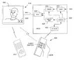
- FIG. 1illustrates, from an oblique perspective, a hand-held remote-control input device including the capability of displaying the position of a user's finger relative to a keypad on an associated video monitor;
- FIG. 2is a drawing of an alternative screen display according to the invention.
- FIG. 3Ais a cross-sectional drawing of a pushbutton including a capacitive touch sensor operative to support two modes of operation according to the invention
- FIG. 3Bis an alternative embodiment of a dual-mode switch including double, electrically conductive membranes
- FIG. 3Crepresents yet a further, alternative dual-mode switch incorporating a plurality of electrically conductive leaf springs
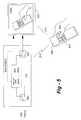
- FIG. 4is a block diagram depicting electrical circuitry used in implementing the invention.
- FIG. 5is a block diagram of an embodiment of the invention facilitating use with an unmodified television receiver.
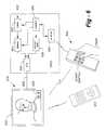
- FIG. 6is a block diagram of a further embodiment of the invention including a dedicated remote-control unit for basic functions.
- FIG. 1there is shown generally at 100 an embodiment of the invention including a hand-held remote-control unit 104 in wireless communication with a video monitor 108 .
- the thumb 112 of an operatorhas initiated a first mode of operation with respect to the “2” key 116 , causing a “2” ( 118 ) to appear on the screen of the monitor 108 .
- the “6” ( 120 ) appearing on the screenis indicative of the fact that the operator had previously entered a “6” through a second, command-execution mode of operation with respect to that key.
- some type of visual indicatoris preferably utilized to show that a particular entry is in the first or confirmatory mode of operation awaiting actual entry.
- the display of the digit “2” ( 118 ) on the screenmay be contained in a block of blinking reverse video or other appropriate graphical representation to indicate that the operator will enter a “2” through further depression of the “2” key, at which time the reverse video will terminate and the “2” numerical command will actually be entered. In this particular case, it will cause the execution of channel-change command channel 62 .
- FIGS. 1 and 4illustrate the use of a wireless link between a dual-mode user input and display device
- a hard-wired connection between the user input and the displaymay alternatively be utilized, and although pushbuttons are discussed herein, other input devices such as trackballs, slide switches, rotary knobs and other controls are well within the scope of the invention.
- the user input and displayform the same piece of equipment (a remote-controlled television, for instance)
- the user inputmay, in fact, be used to control a different piece of equipment, with the display of a television, for example, being conveniently used for temporary display purposes only.
- FIG. 2illustrates at 202 an alternative confirmatory display according to the invention, wherein a facsimile of the user-input device is generated along with an icon 204 representative of the user.
- Such graphical iconswould be preferably generated automatically when the user comes within close physical proximity to the input device.
- the user's fingeror thumb
- the graphical representation 202 of the remotehas come in close physical proximity to the “2” key of a remote unit, as shown in the lower portion of FIG. 1, causing the graphical representation 202 of the remote to appear along with the graphical representation of a user, including a finger hovering over the “2” key as shown, indicating that if the user continues to depress that key, a “2” will be entered.
- FIGS. 3A-3Cillustrate alternative approaches to the implementation of dual-mode pushbuttons according to the invention.
- a pair of spaced-apart electrodes 322 and 324are used to bring about the second, execution mode associated with the switch, and above these electrodes there is a membrane 326 having a capacitive touch sensor 328 in alignment with the electrodes 322 and 324 .
- the electrodes 322 and 324will make electrical contact, effectuating the second, execution mode of operation for that switch.
- FIG. 3Billustrates an alternative two-mode switch wherein a first pair of spaced-apart electrodes 312 and 314 make initiate contact through the downward action of an upwardly-biased pushbutton 310 .
- the material onto which the upper electrode 312 is appliedis sufficiently pliable that even a slight downward pressure will cause electrodes 312 and 314 to make electrical contact. With a further downward, somewhat more aggressive depression of the button 310 , however, electrode 314 will make contact with a lower electrode 316 , thus executing the second mode of operation.
- FIG. 3illustrates how leaf switches may be used together, or instead of the other approaches just described.
- the initiate downward motion of an optional pushbutton 330causes electrical contact to occur between leaf springs 332 and 334 , thus bringing about the first mode of operation, whereas a further downward depression causes contact between leaf spring 334 and 336 , executing the operation indicated through the first, confirmatory mode.
- FIG. 4depicts, in block-diagram form, major electrical functional units associated with implementing the invention in a remote-controlled television arrangement.
- a hand-held remote-control unit 402communicates with a display 404 , preferably through the use of an infrared signal 406 from a transmitter 408 in the remote 402 and a receiver 410 associated with the display.
- a dual-mode user inputis shown generally at 420 in the form of an upper switch 422 used to bring about the first, confirmatory mode of operation and a lower switch 424 used for the actual execution of the command associated with the user input 420 .
- the broken line 426is used to indicate that the switches are in vertical, physical alignment with one another but not meant to imply that both switches need to have moving parts, as in the case of the capacitive touch sensor of FIG. 3 A.
- the switches, which cause a ground contact when activatedmay be held to a logical high state using pull-up resistors 428 , as is typical, and may be scanned by a controller 430 , which is preferably a microprocessor or single-chip microcomputer of conventional design.
- a memory 432may optionally be used, as necessary, to store remote-control codes, for example, in the event that the controller 430 is not equipped for such purpose.
- a separate controller 412is preferably used in conjunction with various other components to cause the display of textual and/or graphical information on display 412 in conjunction with the confirmatory mode of operation of the input 420 .
- a separate controller 414may be used to coordinate operations, receiving information from the infrared receiver 410 , and causing the textual and/or graphical information to be routed from a display generator 416 to the display 412 .
- An auxiliary memory 418may be used, for example, for control-code look up or other purposes.
- tuner ( 430 ) and demodulator ( 440 ) circuitsmay be provided to cause the display of television programming on the display 412 . If the display unit 404 is a monitor only, or forms part of a non-television piece of equipment such as a computer, tuning and demodulation circuits would not be required.
- FIGS. 5 and 6illustrate embodiments of the invention wherein a separate piece of equipment or “set-top box” may be used in conjunction with conventional hardware, including television receivers.
- a user 502is depressing a multi-state button 504 on a remote-control unit 506 provided according to the invention.
- the multi-state button 504includes a first switch to confirm the identity of a command associated with that key, and a second switch being operative to execute the command through a further depression or other technique described herein.
- a wireless signal 510is sent to a unit 520 according to the invention, which causes the incoming video feed or cable line 530 , to be switched from a through-path 531 to the insertion of a display generator 540 through switches 522 and 522 ′.
- the display generator 540 in unit 520causes a picture 550 to be displayed on the display unit 552 , enabling the user 502 to confirm the identity of a command prior to execution.
- a facsimile of the remote unit 506is displayed at 550 , numbers, letters or other indicia may be used in the pre-execution state.
- the unit 506provided by the invention must not only include the capability of sending a wireless signal 510 to the separate unit 520 to effectuate a display on device 552 , but it must also learn at least a subset of the commands of the unit 552 to enable the actual execution of a command upon entry of the second or execution state.
- switches 522are RF switches in the sense that the cable signal itself is bypassed by display generator 540 using RF switches
- a channelmay be demodulated to baseband, with display generator 540 generating a display at baseband video, which may either be fed into the video input of the device 552 , or modulated back onto the RF line 532 .
- FIG. 6illustrates generally at 602 a more sophisticated embodiment of the invention facilitating use with a conventional piece of equipment such as television receiver 610 .
- the embodiment of FIG. 6not only facilitates a picture-in-picture display of a pre-execution key or command
- the remote 604allows certain basic commands such as volume/channel changes and numerical input, to be executed directly by the unit 602 , such that additional commands for the device 610 need not be learned by the remote 604 .
- a separate remote 612would preferably be provided, which a user would need to resort to for more complex operations such as menu/set-up, contrast/brightness, and other controls.
- an incoming video line 620is fed to a tuner 622 and demodulator 624 .
- a display generator 626is used to generate a display 628 on the screen of the device 610 , enabling a channel 630 to be viewed outside of the confirmatory area 628 .
- the display generator 626is merged with the demodulated channel signal through a PIP generator block 640 , which is transferred along path 642 to the device 610 to show both the channel 630 and inset 628 .
- a controller 650is responsible for coordinating all of the functions of the unit 602 , including commands received through infrared receiver 652 .
- the hand-held unit 604may include at least a limited set of buttons such as volume/channel change, and numerical channel keypad entries, enabling the unit 602 to perform these functions directly without having to learn separate codes for the unit 610 .
- the device 604may either learn those codes or be pre-programmed with such codes, preferably through an on-screen programming procedure, or a separate unit 612 may be provided for more sophisticated functions, as discussed with reference to FIG. 5 .
Landscapes
- Engineering & Computer Science (AREA)
- Multimedia (AREA)
- Signal Processing (AREA)
- Human Computer Interaction (AREA)
- General Engineering & Computer Science (AREA)
- Theoretical Computer Science (AREA)
- Physics & Mathematics (AREA)
- General Physics & Mathematics (AREA)
- Computer Networks & Wireless Communication (AREA)
- Business, Economics & Management (AREA)
- Marketing (AREA)
- Details Of Television Systems (AREA)
Abstract
Description
Claims (6)
Priority Applications (1)
| Application Number | Priority Date | Filing Date | Title |
|---|---|---|---|
| US09/829,752US6574083B1 (en) | 1997-11-04 | 2001-04-10 | Electronic equipment interface with command preselection indication |
Applications Claiming Priority (2)
| Application Number | Priority Date | Filing Date | Title |
|---|---|---|---|
| US08/963,712US6215417B1 (en) | 1997-11-04 | 1997-11-04 | Electronic equipment interface with command preselection indication |
| US09/829,752US6574083B1 (en) | 1997-11-04 | 2001-04-10 | Electronic equipment interface with command preselection indication |
Related Parent Applications (1)
| Application Number | Title | Priority Date | Filing Date |
|---|---|---|---|
| US08/963,712Continuation-In-PartUS6215417B1 (en) | 1997-11-04 | 1997-11-04 | Electronic equipment interface with command preselection indication |
Publications (1)
| Publication Number | Publication Date |
|---|---|
| US6574083B1true US6574083B1 (en) | 2003-06-03 |
Family
ID=46279935
Family Applications (1)
| Application Number | Title | Priority Date | Filing Date |
|---|---|---|---|
| US09/829,752Expired - LifetimeUS6574083B1 (en) | 1997-11-04 | 2001-04-10 | Electronic equipment interface with command preselection indication |
Country Status (1)
| Country | Link |
|---|---|
| US (1) | US6574083B1 (en) |
Cited By (25)
| Publication number | Priority date | Publication date | Assignee | Title |
|---|---|---|---|---|
| US20030055648A1 (en)* | 2001-09-14 | 2003-03-20 | Cragun Brian John | Method, apparatus and computer program product for implementing preselection announce for user selectable buttons |
| US20070137901A1 (en)* | 2005-12-16 | 2007-06-21 | E-Lead Electronic Co., Ltd. | Micro-keyboard simulator |
| WO2006083499A3 (en)* | 2005-02-02 | 2007-07-26 | Sbc Knowledge Ventures Lp | Remote control, apparatus, system and methods of using the same |
| US20070285284A1 (en)* | 2006-06-08 | 2007-12-13 | Motorola, Inc | Method and apparatus for keypad manipulation |
| US20080126977A1 (en)* | 2006-11-28 | 2008-05-29 | Keohane Susann M | System and method for providing visual keyboard guides according to a programmable set of keys |
| US20090085764A1 (en)* | 2007-10-02 | 2009-04-02 | Samsung Electronics Co., Ltd. | Remote control apparatus and method thereof |
| US20090108840A1 (en)* | 2007-10-24 | 2009-04-30 | Givens Gerald E | Power Line Sensor |
| US20090109183A1 (en)* | 2007-10-30 | 2009-04-30 | Bose Corporation | Remote Control of a Display |
| US20090165073A1 (en)* | 2007-12-19 | 2009-06-25 | Verizon Data Services Inc. | Input based function preview apparatuses, systems, and methods |
| US20100169842A1 (en)* | 2008-12-31 | 2010-07-01 | Microsoft Corporation | Control Function Gestures |
| US20110109574A1 (en)* | 2009-11-06 | 2011-05-12 | Cipriano Barry V | Touch-Based User Interface Touch Sensor Power |
| US20110113374A1 (en)* | 2009-11-06 | 2011-05-12 | Conor Sheehan | Graphical User Interface User Customization |
| US20110109587A1 (en)* | 2009-11-06 | 2011-05-12 | Andrew Ferencz | Touch-Based User Interface Corner Conductive Pad |
| US20110113380A1 (en)* | 2009-11-06 | 2011-05-12 | John Michael Sakalowsky | Audio/Visual Device Graphical User Interface Submenu |
| US20110113368A1 (en)* | 2009-11-06 | 2011-05-12 | Santiago Carvajal | Audio/Visual Device Graphical User Interface |
| US20110109560A1 (en)* | 2009-11-06 | 2011-05-12 | Santiago Carvajal | Audio/Visual Device Touch-Based User Interface |
| US20110109573A1 (en)* | 2009-11-06 | 2011-05-12 | Deslippe Mark H | Touch-based user interface user selection accuracy enhancement |
| US20110109572A1 (en)* | 2009-11-06 | 2011-05-12 | Deslippe Mark H | Touch-Based User Interface User Operation Accuracy Enhancement |
| US20110109586A1 (en)* | 2009-11-06 | 2011-05-12 | Bojan Rip | Touch-Based User Interface Conductive Rings |
| US20110113371A1 (en)* | 2009-11-06 | 2011-05-12 | Robert Preston Parker | Touch-Based User Interface User Error Handling |
| US20130044262A1 (en)* | 2008-10-14 | 2013-02-21 | Echostar Technologies L.L.C. | Set-top box receiver soft control system and method |
| USD687843S1 (en) | 2009-11-06 | 2013-08-13 | Bose Corporation | Audio/video device with graphical user interface |
| US20140232944A1 (en)* | 2011-10-19 | 2014-08-21 | Thomson Licensing | Remote control with feedback for blind navigation |
| US8839314B2 (en) | 2004-12-01 | 2014-09-16 | At&T Intellectual Property I, L.P. | Device, system, and method for managing television tuners |
| US9201584B2 (en) | 2009-11-06 | 2015-12-01 | Bose Corporation | Audio/visual device user interface with tactile feedback |
Citations (7)
| Publication number | Priority date | Publication date | Assignee | Title |
|---|---|---|---|---|
| US5311175A (en) | 1990-11-01 | 1994-05-10 | Herbert Waldman | Method and apparatus for pre-identification of keys and switches |
| US5594469A (en) | 1995-02-21 | 1997-01-14 | Mitsubishi Electric Information Technology Center America Inc. | Hand gesture machine control system |
| US5889506A (en) | 1996-10-25 | 1999-03-30 | Matsushita Electric Industrial Co., Ltd. | Video user's environment |
| US5917476A (en) | 1996-09-24 | 1999-06-29 | Czerniecki; George V. | Cursor feedback text input method |
| US5936611A (en) | 1995-11-02 | 1999-08-10 | Kabushiki Kaisha Toshiba | On-screen displaying apparatus |
| US6037882A (en) | 1997-09-30 | 2000-03-14 | Levy; David H. | Method and apparatus for inputting data to an electronic system |
| US6215417B1 (en)* | 1997-11-04 | 2001-04-10 | Allen M. Krass | Electronic equipment interface with command preselection indication |
- 2001
- 2001-04-10USUS09/829,752patent/US6574083B1/ennot_activeExpired - Lifetime
Patent Citations (7)
| Publication number | Priority date | Publication date | Assignee | Title |
|---|---|---|---|---|
| US5311175A (en) | 1990-11-01 | 1994-05-10 | Herbert Waldman | Method and apparatus for pre-identification of keys and switches |
| US5594469A (en) | 1995-02-21 | 1997-01-14 | Mitsubishi Electric Information Technology Center America Inc. | Hand gesture machine control system |
| US5936611A (en) | 1995-11-02 | 1999-08-10 | Kabushiki Kaisha Toshiba | On-screen displaying apparatus |
| US5917476A (en) | 1996-09-24 | 1999-06-29 | Czerniecki; George V. | Cursor feedback text input method |
| US5889506A (en) | 1996-10-25 | 1999-03-30 | Matsushita Electric Industrial Co., Ltd. | Video user's environment |
| US6037882A (en) | 1997-09-30 | 2000-03-14 | Levy; David H. | Method and apparatus for inputting data to an electronic system |
| US6215417B1 (en)* | 1997-11-04 | 2001-04-10 | Allen M. Krass | Electronic equipment interface with command preselection indication |
Cited By (44)
| Publication number | Priority date | Publication date | Assignee | Title |
|---|---|---|---|---|
| US20030055648A1 (en)* | 2001-09-14 | 2003-03-20 | Cragun Brian John | Method, apparatus and computer program product for implementing preselection announce for user selectable buttons |
| US8839314B2 (en) | 2004-12-01 | 2014-09-16 | At&T Intellectual Property I, L.P. | Device, system, and method for managing television tuners |
| WO2006083499A3 (en)* | 2005-02-02 | 2007-07-26 | Sbc Knowledge Ventures Lp | Remote control, apparatus, system and methods of using the same |
| US7307574B2 (en)* | 2005-02-02 | 2007-12-11 | Sbc Knowledge Ventures, Lp | Remote control, apparatus, system and methods of using the same |
| US8228224B2 (en) | 2005-02-02 | 2012-07-24 | At&T Intellectual Property I, L.P. | System and method of using a remote control and apparatus |
| US20070137901A1 (en)* | 2005-12-16 | 2007-06-21 | E-Lead Electronic Co., Ltd. | Micro-keyboard simulator |
| US7646315B2 (en)* | 2006-06-08 | 2010-01-12 | Motorola, Inc. | Method and apparatus for keypad manipulation |
| US20070285284A1 (en)* | 2006-06-08 | 2007-12-13 | Motorola, Inc | Method and apparatus for keypad manipulation |
| US20080126977A1 (en)* | 2006-11-28 | 2008-05-29 | Keohane Susann M | System and method for providing visual keyboard guides according to a programmable set of keys |
| US7831923B2 (en)* | 2006-11-28 | 2010-11-09 | International Business Machines Corporation | Providing visual keyboard guides according to a programmable set of keys |
| US20090085764A1 (en)* | 2007-10-02 | 2009-04-02 | Samsung Electronics Co., Ltd. | Remote control apparatus and method thereof |
| US20090108840A1 (en)* | 2007-10-24 | 2009-04-30 | Givens Gerald E | Power Line Sensor |
| US20090109183A1 (en)* | 2007-10-30 | 2009-04-30 | Bose Corporation | Remote Control of a Display |
| US20090165073A1 (en)* | 2007-12-19 | 2009-06-25 | Verizon Data Services Inc. | Input based function preview apparatuses, systems, and methods |
| WO2009085523A1 (en)* | 2007-12-19 | 2009-07-09 | Verizon Data Services Llc | Input based function preview apparatuses, systems, and methods |
| US8082566B2 (en)* | 2007-12-19 | 2011-12-20 | Verizon Patent And Licensing Inc. | Input based function preview apparatuses, systems, and methods |
| US9013637B2 (en)* | 2008-10-14 | 2015-04-21 | Echostar Technologies L.L.C. | Set-top box receiver soft control system and method |
| US20140259063A1 (en)* | 2008-10-14 | 2014-09-11 | Echostar Technologies L.L.C. | Set-top box receiver soft control system and method |
| US8730406B2 (en)* | 2008-10-14 | 2014-05-20 | Echostar Technologies L.L.C. | Set-top box receiver soft control system and method |
| US20130044262A1 (en)* | 2008-10-14 | 2013-02-21 | Echostar Technologies L.L.C. | Set-top box receiver soft control system and method |
| US20100169842A1 (en)* | 2008-12-31 | 2010-07-01 | Microsoft Corporation | Control Function Gestures |
| US20110109586A1 (en)* | 2009-11-06 | 2011-05-12 | Bojan Rip | Touch-Based User Interface Conductive Rings |
| US8686957B2 (en) | 2009-11-06 | 2014-04-01 | Bose Corporation | Touch-based user interface conductive rings |
| US20110113371A1 (en)* | 2009-11-06 | 2011-05-12 | Robert Preston Parker | Touch-Based User Interface User Error Handling |
| US20110109573A1 (en)* | 2009-11-06 | 2011-05-12 | Deslippe Mark H | Touch-based user interface user selection accuracy enhancement |
| US20110109560A1 (en)* | 2009-11-06 | 2011-05-12 | Santiago Carvajal | Audio/Visual Device Touch-Based User Interface |
| US8350820B2 (en) | 2009-11-06 | 2013-01-08 | Bose Corporation | Touch-based user interface user operation accuracy enhancement |
| US20110113368A1 (en)* | 2009-11-06 | 2011-05-12 | Santiago Carvajal | Audio/Visual Device Graphical User Interface |
| USD687843S1 (en) | 2009-11-06 | 2013-08-13 | Bose Corporation | Audio/video device with graphical user interface |
| US8601394B2 (en) | 2009-11-06 | 2013-12-03 | Bose Corporation | Graphical user interface user customization |
| US8638306B2 (en) | 2009-11-06 | 2014-01-28 | Bose Corporation | Touch-based user interface corner conductive pad |
| US8669949B2 (en) | 2009-11-06 | 2014-03-11 | Bose Corporation | Touch-based user interface touch sensor power |
| US20110109572A1 (en)* | 2009-11-06 | 2011-05-12 | Deslippe Mark H | Touch-Based User Interface User Operation Accuracy Enhancement |
| US8692815B2 (en) | 2009-11-06 | 2014-04-08 | Bose Corporation | Touch-based user interface user selection accuracy enhancement |
| US20110113380A1 (en)* | 2009-11-06 | 2011-05-12 | John Michael Sakalowsky | Audio/Visual Device Graphical User Interface Submenu |
| US8736566B2 (en) | 2009-11-06 | 2014-05-27 | Bose Corporation | Audio/visual device touch-based user interface |
| US9354726B2 (en) | 2009-11-06 | 2016-05-31 | Bose Corporation | Audio/visual device graphical user interface submenu |
| US20110109587A1 (en)* | 2009-11-06 | 2011-05-12 | Andrew Ferencz | Touch-Based User Interface Corner Conductive Pad |
| US20110113374A1 (en)* | 2009-11-06 | 2011-05-12 | Conor Sheehan | Graphical User Interface User Customization |
| US20110109574A1 (en)* | 2009-11-06 | 2011-05-12 | Cipriano Barry V | Touch-Based User Interface Touch Sensor Power |
| US9172897B2 (en) | 2009-11-06 | 2015-10-27 | Bose Corporation | Audio/visual device graphical user interface |
| US9201584B2 (en) | 2009-11-06 | 2015-12-01 | Bose Corporation | Audio/visual device user interface with tactile feedback |
| US20140232944A1 (en)* | 2011-10-19 | 2014-08-21 | Thomson Licensing | Remote control with feedback for blind navigation |
| US9591250B2 (en)* | 2011-10-19 | 2017-03-07 | Thomson Licensing | Remote control with feedback for blind navigation |
Similar Documents
| Publication | Publication Date | Title |
|---|---|---|
| US6574083B1 (en) | Electronic equipment interface with command preselection indication | |
| US6215417B1 (en) | Electronic equipment interface with command preselection indication | |
| US7271734B2 (en) | Remote control transmitter | |
| US5982355A (en) | Multiple purpose controls for electrical systems | |
| KR19980018618A (en) | Remote control device | |
| US20040090423A1 (en) | Remote controlled video display GUI using 2-directional pointing | |
| JP2015122813A (en) | User interface for set top box | |
| US20090207134A1 (en) | Remote control apparatus with integrated positional responsive alphabetic keyboard | |
| WO2001041308A1 (en) | Electronic equipment interface with command preselection indication | |
| EP2315436A1 (en) | Image processing apparatus and input control method thereof | |
| JP2001028790A (en) | Remote control device | |
| KR20030046094A (en) | Remote control device and method based on motion recognition of the same | |
| JP4214874B2 (en) | Electronics | |
| JP3239492B2 (en) | Remote control system | |
| JPH08163392A (en) | Remote commander | |
| JPH02284316A (en) | Operation device | |
| KR101339035B1 (en) | Folder type remocon | |
| JP2003110875A (en) | Digital television receiver | |
| WO2018041527A1 (en) | Image display device remote controller with double-side usability | |
| JPH10326141A (en) | Wireless keyboard device | |
| JP4036823B2 (en) | Remote control device | |
| KR100278679B1 (en) | User Control Mode Switching Method Using Broadcast Status Display Window | |
| CN103294176B (en) | A kind of input media | |
| KR100918935B1 (en) | Motion sensing remote controller | |
| JP4087331B2 (en) | Remote control device |
Legal Events
| Date | Code | Title | Description |
|---|---|---|---|
| STCF | Information on status: patent grant | Free format text:PATENTED CASE | |
| FEPP | Fee payment procedure | Free format text:PAT HOLDER NO LONGER CLAIMS SMALL ENTITY STATUS, ENTITY STATUS SET TO UNDISCOUNTED (ORIGINAL EVENT CODE: STOL); ENTITY STATUS OF PATENT OWNER: LARGE ENTITY | |
| AS | Assignment | Owner name:SYNAPTICS INCORPORATED, CALIFORNIA Free format text:ASSIGNMENT OF ASSIGNORS INTEREST;ASSIGNORS:KRASS, ALLEN M.;POSA, JOHN G.;REEL/FRAME:018268/0941 Effective date:20060901 | |
| FPAY | Fee payment | Year of fee payment:4 | |
| FPAY | Fee payment | Year of fee payment:8 | |
| AS | Assignment | Owner name:WELLS FARGO BANK, NATIONAL ASSOCIATION, NORTH CARO Free format text:SECURITY INTEREST;ASSIGNOR:SYNAPTICS INCORPORATED;REEL/FRAME:033888/0851 Effective date:20140930 | |
| FPAY | Fee payment | Year of fee payment:12 | |
| AS | Assignment | Owner name:WELLS FARGO BANK, NATIONAL ASSOCIATION, NORTH CAROLINA Free format text:SECURITY INTEREST;ASSIGNOR:SYNAPTICS INCORPORATED;REEL/FRAME:044037/0896 Effective date:20170927 Owner name:WELLS FARGO BANK, NATIONAL ASSOCIATION, NORTH CARO Free format text:SECURITY INTEREST;ASSIGNOR:SYNAPTICS INCORPORATED;REEL/FRAME:044037/0896 Effective date:20170927 |