US6574015B1 - Optical depolarizer - Google Patents
Optical depolarizerDownload PDFInfo
- Publication number
- US6574015B1 US6574015B1US09/314,240US31424099AUS6574015B1US 6574015 B1US6574015 B1US 6574015B1US 31424099 AUS31424099 AUS 31424099AUS 6574015 B1US6574015 B1US 6574015B1
- Authority
- US
- United States
- Prior art keywords
- light signal
- signal
- optical
- conduit
- component signal
- Prior art date
- Legal status (The legal status is an assumption and is not a legal conclusion. Google has not performed a legal analysis and makes no representation as to the accuracy of the status listed.)
- Expired - Lifetime
Links
Images


Classifications
- G—PHYSICS
- G02—OPTICS
- G02B—OPTICAL ELEMENTS, SYSTEMS OR APPARATUS
- G02B6/00—Light guides; Structural details of arrangements comprising light guides and other optical elements, e.g. couplings
- G02B6/24—Coupling light guides
- G02B6/26—Optical coupling means
- G02B6/27—Optical coupling means with polarisation selective and adjusting means
- G02B6/2706—Optical coupling means with polarisation selective and adjusting means as bulk elements, i.e. free space arrangements external to a light guide, e.g. polarising beam splitters
- G02B6/2713—Optical coupling means with polarisation selective and adjusting means as bulk elements, i.e. free space arrangements external to a light guide, e.g. polarising beam splitters cascade of polarisation selective or adjusting operations
- G02B6/272—Optical coupling means with polarisation selective and adjusting means as bulk elements, i.e. free space arrangements external to a light guide, e.g. polarising beam splitters cascade of polarisation selective or adjusting operations comprising polarisation means for beam splitting and combining
- G—PHYSICS
- G02—OPTICS
- G02B—OPTICAL ELEMENTS, SYSTEMS OR APPARATUS
- G02B6/00—Light guides; Structural details of arrangements comprising light guides and other optical elements, e.g. couplings
- G02B6/24—Coupling light guides
- G02B6/26—Optical coupling means
- G02B6/27—Optical coupling means with polarisation selective and adjusting means
- G02B6/2726—Optical coupling means with polarisation selective and adjusting means in or on light guides, e.g. polarisation means assembled in a light guide
- G02B6/274—Optical coupling means with polarisation selective and adjusting means in or on light guides, e.g. polarisation means assembled in a light guide based on light guide birefringence, e.g. due to coupling between light guides
- G—PHYSICS
- G02—OPTICS
- G02B—OPTICAL ELEMENTS, SYSTEMS OR APPARATUS
- G02B6/00—Light guides; Structural details of arrangements comprising light guides and other optical elements, e.g. couplings
- G02B6/24—Coupling light guides
- G02B6/26—Optical coupling means
- G02B6/27—Optical coupling means with polarisation selective and adjusting means
- G02B6/2753—Optical coupling means with polarisation selective and adjusting means characterised by their function or use, i.e. of the complete device
- G02B6/2786—Reducing the polarisation degree, i.e. depolarisers, scramblers, unpolarised output
- G—PHYSICS
- G11—INFORMATION STORAGE
- G11B—INFORMATION STORAGE BASED ON RELATIVE MOVEMENT BETWEEN RECORD CARRIER AND TRANSDUCER
- G11B11/00—Recording on or reproducing from the same record carrier wherein for these two operations the methods are covered by different main groups of groups G11B3/00 - G11B7/00 or by different subgroups of group G11B9/00; Record carriers therefor
- G11B11/10—Recording on or reproducing from the same record carrier wherein for these two operations the methods are covered by different main groups of groups G11B3/00 - G11B7/00 or by different subgroups of group G11B9/00; Record carriers therefor using recording by magnetic means or other means for magnetisation or demagnetisation of a record carrier, e.g. light induced spin magnetisation; Demagnetisation by thermal or stress means in the presence or not of an orienting magnetic field
- G11B11/105—Recording on or reproducing from the same record carrier wherein for these two operations the methods are covered by different main groups of groups G11B3/00 - G11B7/00 or by different subgroups of group G11B9/00; Record carriers therefor using recording by magnetic means or other means for magnetisation or demagnetisation of a record carrier, e.g. light induced spin magnetisation; Demagnetisation by thermal or stress means in the presence or not of an orienting magnetic field using a beam of light or a magnetic field for recording by change of magnetisation and a beam of light for reproducing, i.e. magneto-optical, e.g. light-induced thermomagnetic recording, spin magnetisation recording, Kerr or Faraday effect reproducing
- G11B11/10532—Heads
- G11B11/10541—Heads for reproducing
- G11B11/10543—Heads for reproducing using optical beam of radiation
- G—PHYSICS
- G11—INFORMATION STORAGE
- G11B—INFORMATION STORAGE BASED ON RELATIVE MOVEMENT BETWEEN RECORD CARRIER AND TRANSDUCER
- G11B7/00—Recording or reproducing by optical means, e.g. recording using a thermal beam of optical radiation by modifying optical properties or the physical structure, reproducing using an optical beam at lower power by sensing optical properties; Record carriers therefor
- G11B7/12—Heads, e.g. forming of the optical beam spot or modulation of the optical beam
- G11B7/135—Means for guiding the beam from the source to the record carrier or from the record carrier to the detector
- G11B7/1384—Fibre optics
Definitions
- the present inventiongenerally relates to optical systems. More specifically, the present invention relates to noise reduction in the transmission of optical signals.
- a magneto-optical (MO) storage systema laser in conjunction with an optical fiber are used with a MO media to attain data storage densities beyond conventional magnetic data storage systems.
- This type of systemrelies upon propagating a light signal through an optical fiber and reflecting off of a MO media. Based upon the polarized logic state of the location on the MO media, which the light signal contacts, a Kerr effect slightly alters the polarization of the light signal, thereby enabling the light signal to carry the logic state of the MO media back to a differential detector.
- the differential detectortransforms this polarized light signal into an electrical data signal, which is processed by a computing device, such as a personal computer.
- fiber optic current sensorsinclude a sensing optical fiber, which is wound with an integral number of turns around a current carrying wire and with each point in the sensing fiber having a constant sensitivity to the magnetic field.
- Current flowing through the wireinduces a magnetic field, which through the Faraday effect, rotates the plane of polarization of the light traveling in an optical fiber around the current carrying wire.
- This rotation of the state of polarization of the light due to the electrical currentis measured by either injecting light with a well defined polarization state into the designated sensing region and analyzing the polarization state of the light after it exits this same sensing region or by measuring the velocity change of a circularly polarized light wave traversing the sensing region.
- DFBdistributed feedback
- a preferred embodiment of the systemincludes a multi-mode laser, a leaky beam splitter (LBS), a first half wave plate (HWP 1 ), a second half wave plate (HWP 2 ), a depolarizer, an optical fiber, a first quarter wave plate (QWP 1 ), a second quarter wave plate (QWP 2 ) and a differential detection module.
- the multi-mode lasergenerates the main light signal, which is used as a read signal for carrying the polarization state of the main light signal from a specific location on the MO media or the sensing region to the differential detection module.
- the laseris modulated on and off at a radio frequency, which is dependent upon the optical path lengths associated with the depolarizer and the optical fiber.
- the depolarizer and the optical fiberare part of a continuous birefringent conduit for the polarization and propagation of the main light signal between the reflective medium or sensing region and the differential detection module.
- the HWP 1 and the HWP 2 in conjunction with the QWP 1align and polarize the main light signal to ensure that the first and second components of the main light signal propagate along each optical path length of the depolarizer and each axis of the optical fiber
- the two components of the main light signalwill have a net zero optical path difference.
- the depolarizerdepolarizes these parasitic light signals, so as to destroy coherent interference between the two parasitic light signals, which minimizes the MPN effects on the main light signal.
- the LBSwhich allows a main polarized mode of light to enter the depolarizer and the optical fiber on the forward path, reflects on the return path part of the main polarized mode and most of the perpendicularly polarized mode of the main light signal toward the differential detection module.
- the QWP 2reorients the reflected main light signal to ensure that the logic states within the main light signal are more easily detectable by the differential detection-module.
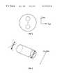
- FIG. 1illustrates a depolarizer of a preferred embodiment of the present invention.
- FIG. 2illustrates multiple pulsed longitudinal mode signals of a preferred embodiment of the present invention.
- FIG. 3illustrates a birefringent optical fiber of a preferred embodiment of the present invention.
- FIG. 4illustrates coherent interference of parasitic light signals of a preferred embodiment of the present invention.
- FIG. 5illustrates an all fiber depolarizer of an alternative embodiment of the present invention.
- FIG. 1illustrates a low noise optical system 100 of a preferred embodiment of the present invention, which can be integrated into optical systems, such as magneto-optical (MO) storage devices that include a magnetic media with a reflective surface undeneath.
- the system 100includes a multi-mode laser 110 , a leaky beam splitter (LBS) 120 , a first half-wave plate (HWP 1 ) 130 , a second half-wave plate (HWP 2 ) 177 , a first quarter wave plate (QWP 1 ) 185 , a second quarter wave plate (QWP 2 ) 114 , a depolarizer 140 , a plurality of polarization-maintaining (PM) fibers 180 , a magneto-optical (MO) media 190 and a differential detection module 116 .
- PMpolarization-maintaining
- the multi-mode laser 110which in a preferred embodiment is a Fabry-Perot (FP) laser diode, generates a signal comprising multiple pulsed longitudinal modes (main light), which transports data from the MO media 190 to the differential detection module 116 . Due to the dynamic partitioning between the longitudinal modes, the light signal has a relatively constant power.
- FPFabry-Perot
- the LBS 120which is coupled to the multi-mode laser 110 , receives the main outgoing p-polarized light beam from the laser 110 and transmits most of this polarized light (e.g., approximately 80%) of the main light signal along a forward path toward the depolarizer 140 and the MO media 190 .
- the HWP 1 130which is coupled between the LBS 120 and a first end of the depolarizer 140 , rotates the main light polarization by approximately 45 degrees to ensure that upon entering the depolarizer 140 on the forward path, the main light signal will split into two relatively equal components with the first component maintained as a p-polarized light (p-wave) signal and the second component transformed as an s-polarized light (s-wave) signal.
- p-wavep-polarized light
- s-waves-polarized light
- the HWP 2 177aligns the s-wave signal to propagate along the slow axis n slow of the PM fiber 180 and the p-wave signal to propagate along the fast axis n fast of the PM fiber 180 .
- the s-wave and p-wave signalsare aligned to propagate along the opposite axes.
- the slow axis of the PM fiber 180has a refractive index, which is larger than the refractive index of the fast axis, the s-wave signal will propagate along the slow axis at a slower phase velocity, which corresponds to a longer optical path length than the optical path length of the fast axis.
- These differing optical path lengths in both the depolarizer 140 and the PM fiber 180result in a forward optical path length difference and corresponding time delay between the s-wave signal and the p-wave signal.
- the QWP 1 185receives, reorients by 90 degrees and retransmits the main light signal on a return path through the opposite axes of the PM fiber 180 and opposite optical paths of the depolarizer 140 .
- the QWP 1 185is aligned at 45° with respect to the fiber axes so that the QWP 1 185 converts the two linearly polarized components, the s-wave signal and the p-wave signal, into left and right circularly polarized states.
- the senses of the two circular states of the componentsare reversed (e.g., right polarization becomes left polarization and left polarization becomes right polarization).
- the circular states of the componentsare converted back into linear states, but with a 90° rotation in the polarization state.
- This rotationresults in each component propagating on the return path upon an opposing axis and optical path length, thereby compensating for the path difference effects of the forward path difference by equalizing the net optical path length difference of each component.
- the first component of the main light signalwhich originally propagated as a p-wave signal on the forward path along the short optical path length of the depolarizer 140 and along the fast axis of the PM fiber 180 , now propagates on the return path as an s-wave signal along the slow axis of the PM fiber 180 and the long optical path length of the depolarizer 140 .
- the original s-wave signalwhich is now a p-wave signal, propagates on the return path along the fast axis of the PM fiber 180 and the short optical path length of the depolarizer 140 .
- the recombined main light signalwhich exits the first end of the depolarizer 140 does not experience a net optical path difference like the main light signal exiting the second end of the PM fiber 180 .
- the system 100ideally can eliminate the optial path length difference and the corresponding time delay between the two components of the main light signal by providing a net optical path difference of zero, unavoidable misalignment errors within the system 100 as well as manufacturing process, aging and temperature variations cause a parasitic light signal to develop and significantly affect the ability of the main light signal to transport data.
- errors in the thickness or the rotational alignment of the QWP 1 185 and the alignment between the PM fiber 180 and the depolarizer 140will produce parasitic light signals.
- the main light signalafter leaving the PM fiber 180 in the forward path, passes through QWP 1 185 , reflects off of the MO disk 190 and once again propagates through QWP 1 185 .
- Double passing QWP 1 185converts the outgoing s-wave signal into a p-wave signal on the return path and the outgoing p-wave signal into an s-wave signal on the return path.
- QWP 1 185has errors in either its retardation (e.g., its phase shift departs from 90 degrees) or its 45 degree orientation, parasitic light signals will exist. These parasitic light signals correspond to that portion of the outgoing light that is not properly converted by QWP 1 185 , namely outgoing s-waves that propagate on the return path as s-waves and outgoing p-waves that propagate on the return path asp-waves.
- each component of the parasitic light signalWhile each polarization component of the main light signal, propagates along an equal optical path length, each component of the parasitic light signal only travels along one of the two optical paths lengths. This difference in the optical path lengths of these two parasitic light signals results in the creation of interference between the two parasitic light signals, which causes MPN to be converted to intensity noise.
- a misalignment sensitivity between the PM fiber 180 and the depolarizer 140is avoided by grouping all of the PM fibers 180 into an array such that all of the axes of the PM fibers 180 are well aligned (e.g., with less than 1 degree of error) with respect to one another.
- An alternative embodiment for avoiding misalignment between the PM fibers 180 and the depolarizer 140is to utilize a dynamic electrically controlled polarization rotator (e.g., by placing HWP 2 177 on an electrically controlled rotation stage or by replacing HWP 2 177 with a nematic liquid crystal cell used in combination with a quarter-wave plate) that can be used between the depolarizer 140 and the first end of the PM fiber 180 to provide active alignment for switching between PM fibers 180 .
- a dynamic electrically controlled polarization rotatore.g., by placing HWP 2 177 on an electrically controlled rotation stage or by replacing HWP 2 177 with a nematic liquid crystal cell used in combination with a quarter-wave plate
- the sensitivity of the noise performance of a non-ideal QWP 1 185is minimized by making parasitic light signals incoherent to avoid interference.
- the parasitic light signalwhich is generated by the QWP 1 185 , propagates on the return path along the same axis and optical path length as the corresponding portion of the main light signal originally propagated along in the forward path. By failing to travel on the opposite axis and optical path length, this parasitic light signal experiences a net optical path length difference which causes the parasitic light signals to interfere with the main light signal and with each other. Fortunately, the errors caused by the interference between each parasitic wave and the main wave are equal and opposite and thus cancel. However, the error created by the interference between the two parasitic waves remains.
- the parasitic light signal on one axis and the parasitic light signal on the opposite axiswill, upon recombining, produce a wavelength dependent polarization state which results in strong conversion of MPN into the polarization noise, which causes the differential detection module 116 to have difficulty detecting the data transported by the main light signal.
- the depolarizer 140eliminates the effects of MPN and increases the tolerance of misalignments in the optical components (primarily QWP 1 185 ) by relying upon a significantly large optical path difference, which depolarizes the parasitic light signals and allows for the coherent interference between the parasitic light signals to be destroyed thereby minimizing the effects of MPN on the main light signal. Since the parasitic light signals propagate along different fiber lengths and optical path lengths on the return path than the corresponding portion of the main light signal, a p-wave parasitic light signal would propagate a shorter optical path length and an s-wave parasitic light signal would propagate a longer optical path length. This difference in the net optical path length between the two parasitic light signals results in the p-wave parasitic light signal becoming depolarized with regard to the s-wave parasitic light signal.
- the depolarizer 140comprises a first polarization beam splitter (PBS 1 ) 169 , a second polarization beam splitter (PBS 2 ) 170 , an optical fiber 165 a first lens 175 and a second lens 182 .
- PBS 1first polarization beam splitter
- PBS 2second polarization beam splitter
- the HWP 1 130Prior to the main light signal entering the depolarizer 140 on the forward path, the HWP 1 130 orients the light signal by 45 degrees to ensure that the PBS 1 169 , which is coupled to the HWP 1 130 , receives and splits the main light signal into two equal-amplitude components with the transmitted component, a p-wave signal, and the reflected. component, an s-wave signal.
- the depolarizer 140then allows the s-wave signal to propagate along the long optical path length by redirecting the s-wave signal to travel through the first lens 175 , onto the optical fiber 165 , and through the second lens 182 .
- the first lens 175 and the second lens 182are graded index (GRIN) lenses (e.g., with a 0.25 pitch).
- the first lens 175accepts and outputs a collimated free-space beam of the appropriate diameter into the optical fiber 165 .
- the optical fiber 165 of the depolarizer 140can be a polarizing fiber (e.g., PZ fiber), a PM fiber, or a low-birefringence (Lo-Bi) fiber.
- the primary constraint for a preferred embodimentis that the optical fiber 165 must propagate a single linear polarization state (e.g., s-wave signal) with a high extinction ratio.
- the p-wave signalpropagates along the short optical path length by direct transmission through PBS 1 169 and PBS 2 170 .
- the PBS 2 170receives both the s-wave signal from the second lens 182 and the p-wave signal, recombines them back into the main light signal and directs the main light signal through the HWP 2 , 177 (or an equivalent polarization rotator) into one of the set of PM fibers 180 , which effectively acts as an extension of the depolarizer 140 .
- the alignment between the depolarizer 140 and the PM fiber 180 by the HWP 2 177results in the s- and p-waves entering onto either the fast or slow fiber axis of the PM fiber 180 . Either fiber axis can be used for the s- or p-waves.
- FIG. 5illustrates an alternative embodiment of the system 500 with an all-fiber version of the depolarizer 540 .
- this depolarizer 540comprises polarization beam splitters 510 , 515 which function in a similar manner as the PBS 169 , 170 .
- the long optical path length of the depolarizer 540is provided by optical fiber 545
- the small optical path length of the depolarizer 540is provided by optical fiber 543 .
- the axes of optical fiber 540are aligned in such a manner that the main light signal propagates along one (e.g., fast) axis of the PM fiber on the forward path and the opposite (e.g., slow) axis on the return path.
- the polarization of the components of the main lightare swapped upon double pass through the QWP 1 185 .
- the QWP 1 185due to the imperfectness of the QWP 1 185 , there also will be two parasitic light signals that travel the same axis on the return path as the corresponding component of the main light signal propagated along the forward path of this system 500 .
- the parasitic light signalalso propagates along the same optical fiber on the return path as the corresponding component of the main light signal propagated on the forward path, these parasitic light signals interfere at the output of the first polarization beam splitter 510 and interfere with the main light signal.
- the first GRIN lens 520 and the second GRIN lens 530are placed at the input and the output of the fibers 543 and 545 .
- This all fiber depolarizer 540 approacheases the difficulty of alignment of the components compared to the free-space version of FIG. 1 .
- angle-cleaved optical fibers of a preferred embodimentgenerally result in the forward coupling efficiency for the system 500 to be as high as approximately 70-80%. End face reflections from straight-cleaved fibers also can be eliminated by using indexmatching epoxy between the GRIN lenses 520 and 530 and the ends of the fibers 540 , 543 , 545 .
- this system 500also could be constructed from one long piece of PM fiber, but the corresponding length of optical fiber would be approximately 1 kilometer.
- the differential round-trip polarization delay between the two parasitic wavesmay be made to be substantially an integer times the double-pass delay in the multi-mode laser diode cavity 110 .
- the optical path length difference between the s- and p- paths extending from the PBS 169 through QWP 1 185may be made to be substantially an integer times the single pass delay of the laser cavity 110 .
- the resultant interference of the parasitic wavesdoes not substantially change because the parasitic wave interference does not produce noise.
- the parasitic wavesdo interfere to give an output signal.
- this outputonly changes as the optical path length difference between the s- and p- paths change, rather than with the hopping of the light-source modes.
- changes in the optical path length differenceare slow with time because the changes are largely dependent on temperature and strain effects in the optical fibers 543 and 545 , whereas for mode hopping, the phenomenon is rapid.
- the polarization noise associated with the parasitic wavesis relegated to a low frequency band, which is below the band of interest for the applications.
Landscapes
- Physics & Mathematics (AREA)
- Optics & Photonics (AREA)
- General Physics & Mathematics (AREA)
- Optical Communication System (AREA)
Abstract
Description
Claims (34)
Priority Applications (1)
| Application Number | Priority Date | Filing Date | Title |
|---|---|---|---|
| US09/314,240US6574015B1 (en) | 1998-05-19 | 1999-05-18 | Optical depolarizer |
Applications Claiming Priority (2)
| Application Number | Priority Date | Filing Date | Title |
|---|---|---|---|
| US8599498P | 1998-05-19 | 1998-05-19 | |
| US09/314,240US6574015B1 (en) | 1998-05-19 | 1999-05-18 | Optical depolarizer |
Publications (1)
| Publication Number | Publication Date |
|---|---|
| US6574015B1true US6574015B1 (en) | 2003-06-03 |
Family
ID=26773313
Family Applications (1)
| Application Number | Title | Priority Date | Filing Date |
|---|---|---|---|
| US09/314,240Expired - LifetimeUS6574015B1 (en) | 1998-05-19 | 1999-05-18 | Optical depolarizer |
Country Status (1)
| Country | Link |
|---|---|
| US (1) | US6574015B1 (en) |
Cited By (20)
| Publication number | Priority date | Publication date | Assignee | Title |
|---|---|---|---|---|
| US20050047706A1 (en)* | 2003-08-27 | 2005-03-03 | Waagaard Ole Henrik | Method and apparatus for producing depolarized light |
| GB2406166A (en)* | 2003-08-27 | 2005-03-23 | Weatherford Lamb | Producing depolarized light in optical sensing systems |
| US20050096641A1 (en)* | 2003-10-31 | 2005-05-05 | Nidek Co., Ltd. | Laser treatment apparatus |
| US20050094919A1 (en)* | 2002-04-09 | 2005-05-05 | Oplink Communications, Inc., A Delaware Corporation | Depolarizer |
| US20060152733A1 (en)* | 2003-08-27 | 2006-07-13 | Weatherford/Lamb, Inc. | Method and apparatus for reducing crosstalk interference in an inline fabry-perot sensor array |
| US7081959B2 (en) | 2003-08-27 | 2006-07-25 | Optoplan As | Method and apparatus for providing polarization insensitive signal processing for interferometric sensors |
| US20070002694A1 (en)* | 2005-07-02 | 2007-01-04 | Taugher Lawrence N | Guiding optical beam to optically writable surface |
| US20070297054A1 (en)* | 2002-04-18 | 2007-12-27 | General Photonics Corporation, A California Corporation | Optical Depolarizers and DGD Generators Based on Optical Delay |
| WO2007033057A3 (en)* | 2005-09-12 | 2008-07-31 | Nxtphase T & D Corp | Fiber optic current sensor |
| US20090034072A1 (en)* | 2007-07-31 | 2009-02-05 | Dean Jennings | Method and apparatus for decorrelation of spatially and temporally coherent light |
| WO2009085254A1 (en)* | 2007-12-31 | 2009-07-09 | Corning Incorporated | Systems and methods for polarization modulation of an optical signal |
| US7723670B1 (en) | 2007-03-26 | 2010-05-25 | General Photonics Corporation | Optical differential group delay module with folded optical path |
| US20100284054A1 (en)* | 2009-05-08 | 2010-11-11 | Honeywell International Inc. | Modulation of unpolarized light |
| US20130128330A1 (en)* | 2011-11-18 | 2013-05-23 | Ciena Corporation | Fiber optical package interconnect |
| US8573785B2 (en) | 2010-11-23 | 2013-11-05 | Corning Incorporated | Wavelength-switched optical systems |
| CN103954827A (en)* | 2014-04-03 | 2014-07-30 | 易能乾元(北京)电力科技有限公司 | Optical current sensor |
| US9069135B2 (en) | 2012-03-21 | 2015-06-30 | Jds Uniphase Corporation | Optical depolarizer |
| US9437229B2 (en) | 2014-04-09 | 2016-09-06 | Seagate Technology Llc | Isolator element for heat-assisted magnetic recording |
| US20200309869A1 (en)* | 2017-09-29 | 2020-10-01 | Citizen Finedevice Co., Ltd. | Magnetic sensor element and magnetic sensor device |
| US20210223467A1 (en)* | 2020-01-21 | 2021-07-22 | Lumentum Operations Llc | Graded-index fibers and phase elements for in-fiber beam shaping and switching |
Citations (90)
| Publication number | Priority date | Publication date | Assignee | Title |
|---|---|---|---|---|
| US3659915A (en) | 1970-05-11 | 1972-05-02 | Corning Glass Works | Fused silica optical waveguide |
| US3737236A (en) | 1972-01-03 | 1973-06-05 | Corning Glass Works | Magnetooptic readout system utilizing optical waveguide fibers |
| US3859643A (en) | 1973-11-14 | 1975-01-07 | Corning Glass Works | Optical sensing of cylindrical magnetic domains |
| US3900247A (en)* | 1974-02-26 | 1975-08-19 | Northern Electric Co | Optical modulator having compensation for thermal and space charge effects |
| US3942867A (en) | 1973-12-27 | 1976-03-09 | Nippon Electric Co., Ltd. | Optical memory apparatus |
| US4135083A (en) | 1976-05-12 | 1979-01-16 | U.S. Philips Corporation | Optical scanning device |
| US4298245A (en) | 1978-09-21 | 1981-11-03 | Siemens Aktiengesellschaft | Waveguides with a low birefringence |
| US4337531A (en) | 1980-05-12 | 1982-06-29 | Northern Telecom Limited | Scanning head for an optical disc system |
| US4368946A (en) | 1978-02-28 | 1983-01-18 | Ricoh Company, Ltd. | Information recording method and apparatus |
| US4449204A (en) | 1980-03-31 | 1984-05-15 | Agency Of Industrial Science And Technology | Information processing apparatus using a semiconductor laser diode |
| JPS59117180A (en) | 1982-12-23 | 1984-07-06 | Toshiba Corp | Semiconductor light-emitting element |
| US4460989A (en) | 1981-06-22 | 1984-07-17 | Eli Soloman Jacobs | Apparatus for improving focus during playback of an optical data record |
| US4460998A (en) | 1981-03-11 | 1984-07-17 | Nippon Telegraph & Telephone Public Corporation | Semiconductor memory devices |
| US4510544A (en) | 1981-10-16 | 1985-04-09 | Compagnie Internationale Pour L'informatique Cii-Honeywell Bull | Optoelectronic device for reading data contained on a magnetic medium |
| US4532619A (en) | 1982-01-22 | 1985-07-30 | Hitachi, Ltd. | Method and apparatus for reducing semiconductor laser optical noise |
| US4539519A (en) | 1981-04-23 | 1985-09-03 | Max-Planck-Gesellschaft Zur Forderung Der Wissenschaften E.V. | Fiber optics device for measuring the intensity of an electric current utilizing the Faraday effect |
| JPS60261052A (en) | 1984-06-06 | 1985-12-24 | Fujitsu Ltd | Optical head for magneto-optical disks |
| US4581529A (en) | 1983-08-15 | 1986-04-08 | At&T Bell Laboratories | Read/write system for optical disc apparatus with fiber optics |
| US4626679A (en) | 1982-09-22 | 1986-12-02 | Canon Kabushiki Kaisha | Optical head and method of detecting the focus thereof |
| US4626066A (en) | 1983-12-30 | 1986-12-02 | At&T Bell Laboratories | Optical coupling device utilizing a mirror and cantilevered arm |
| US4638153A (en) | 1983-05-26 | 1987-01-20 | Plessey Overseas Limited | Optical fibre sensing arrangements |
| US4683421A (en) | 1985-03-29 | 1987-07-28 | Westinghouse Electric Corp. | Drift compensation technique for a magneto-optic current sensor |
| US4737005A (en) | 1982-12-17 | 1988-04-12 | The United States Of America As Represented By The Secretary Of The Navy | Method for eliminating birefringence in a fiber optic coupler and a coupler polarization corrector |
| US4740951A (en) | 1985-03-13 | 1988-04-26 | Commissariat A L'energie Atomique | Reversible device for the demultiplexing of several light signals in integrated optics |
| US4796226A (en) | 1986-11-18 | 1989-01-03 | Commissariat A L'energie Atomique | Reading head in integrated optics for reading information recorded on a magnetic support |
| US4799210A (en) | 1986-11-05 | 1989-01-17 | Unisys Corporation | Fiber optic read/write head for an optical disk memory system |
| US4806885A (en) | 1986-08-08 | 1989-02-21 | Sumitomo Electric Industries, Ltd. | Magnet-electro-optic effect light modulator |
| US4847823A (en) | 1987-06-19 | 1989-07-11 | Siscan Systems, Inc. | Method and apparatus for reading or measuring magneto-optical storage media using pinhole aperture |
| US4866372A (en) | 1987-05-31 | 1989-09-12 | Hamamatsu Photonics Kabushiki Kaisha | Voltage detector having compensation for polarization change caused by spontaneous birefringence |
| US4945400A (en) | 1988-03-03 | 1990-07-31 | At&T Bell Laboratories | Subassembly for optoelectronic devices |
| US4978190A (en) | 1988-09-20 | 1990-12-18 | Alcatel N.V. | Servo-controlled light coupling between a light-emitting component and an optical fiber |
| US5029023A (en) | 1989-09-29 | 1991-07-02 | Regents Of The University Of California | Laser-amplified motion detector and method |
| US5033043A (en) | 1989-04-19 | 1991-07-16 | Eastman Kodak Company | Optical head apparatus for optical disks |
| US5034679A (en) | 1989-12-14 | 1991-07-23 | Sundstrand Corporation | Polarization feedback control of polarization rotating sensor |
| US5039220A (en) | 1988-09-14 | 1991-08-13 | Phononetics, S.A. | Optical fiber measuring device, gyrometer, central navigation and stabilizing system |
| US5093884A (en) | 1990-06-13 | 1992-03-03 | Commissariat A L'energie Atomique | Integrated monomode spatial optical filter and its method of embodiment |
| US5111326A (en) | 1991-04-25 | 1992-05-05 | United Technologies Corporation | Integrated Kerr shutter and fiber laser optical modulation |
| US5119361A (en) | 1988-09-29 | 1992-06-02 | Asahi Glass Company Ltd. | Optical information readout apparatus |
| US5120953A (en) | 1988-07-13 | 1992-06-09 | Harris Martin R | Scanning confocal microscope including a single fibre for transmitting light to and receiving light from an object |
| US5135295A (en) | 1990-02-27 | 1992-08-04 | Queen's University At Kingston | Fiber-optic piezoelectric devices |
| US5137359A (en) | 1991-03-18 | 1992-08-11 | Litton Systems, Inc. | Digital phase modulator for fiber optic sagnac interferometer |
| US5152597A (en) | 1990-12-03 | 1992-10-06 | Eastman Kodak Company | Magneto-optic readout using a polarization-preserving optical fiber |
| US5161133A (en) | 1989-09-29 | 1992-11-03 | International Business Machines Corporation | Magneto-optical storage system |
| US5172369A (en) | 1990-03-02 | 1992-12-15 | Pioneer Electronic Corporation | Optical pickup, optical information recording carrier and recording and reproducing apparatus thereof |
| US5191387A (en) | 1990-01-10 | 1993-03-02 | Ando Electric Co., Ltd. | Polarization control system |
| US5212583A (en) | 1992-01-08 | 1993-05-18 | Hughes Aircraft Company | Adaptive optics using the electrooptic effect |
| US5218582A (en) | 1990-12-03 | 1993-06-08 | Eastman Kodak Company | Magneto-optic readout using a polarization-preserving optical guide |
| US5229834A (en) | 1990-01-12 | 1993-07-20 | Bertin & Cie | Sensor for detecting and measuring the angle of rotation of a plane of light polarization |
| US5233444A (en) | 1989-07-25 | 1993-08-03 | Olympus Optical Co., Ltd. | Focus error detecting apparatus |
| US5245491A (en)* | 1989-06-02 | 1993-09-14 | Hitachi Cable Limited | Magneto-optical head employing optical fiber connected stationary and movable portions |
| US5272330A (en) | 1990-11-19 | 1993-12-21 | At&T Bell Laboratories | Near field scanning optical microscope having a tapered waveguide |
| US5278812A (en) | 1992-02-18 | 1994-01-11 | At&T Bell Laboratories | Tracking and focussing functions in optical disk apparatus |
| EP0582405A1 (en) | 1992-08-03 | 1994-02-09 | AT&T Corp. | Method of drawing an optical fibre and fibre produced thereby |
| US5288997A (en) | 1990-11-19 | 1994-02-22 | At&T Bell Laboratories | Manufacturing method, including near-field optical microscopic examination of a magnetic bit pattern |
| US5289454A (en) | 1991-12-19 | 1994-02-22 | Minnesota Mining And Manufacturing Company | Optical disc addressing devices a method of use thereof |
| US5311360A (en) | 1992-04-28 | 1994-05-10 | The Board Of Trustees Of The Leland Stanford, Junior University | Method and apparatus for modulating a light beam |
| US5323373A (en) | 1991-07-11 | 1994-06-21 | Sony Corporation | Optical pickup device |
| US5325116A (en) | 1992-09-18 | 1994-06-28 | Texas Instruments Incorporated | Device for writing to and reading from optical storage media |
| US5347297A (en) | 1991-12-13 | 1994-09-13 | Eastman Kodak Company | Apparatus and method for optimizing performance in an optical storage system read/write head |
| US5383048A (en) | 1993-02-03 | 1995-01-17 | Seaver; George | Stress-optical phase modulator and modulation system and method of use |
| US5389779A (en) | 1993-07-29 | 1995-02-14 | At&T Corp. | Method and apparatus for near-field, scanning, optical microscopy by reflective, optical feedback |
| EP0650133A2 (en) | 1993-10-25 | 1995-04-26 | Symbol Technologies, Inc. | Integrated scanner on a common substrate |
| WO1995013638A1 (en) | 1993-11-08 | 1995-05-18 | International Business Machines Corporation | Hybrid external coupled cavity semiconductor laser device |
| US5434501A (en)* | 1994-04-29 | 1995-07-18 | The United States Of America As Represented By The Secretary Of The Navy | Polarization insensitive current and magnetic field optic sensor |
| US5446574A (en) | 1993-03-26 | 1995-08-29 | Telefonaktiebolaget Lm Ericsson | System and method for dispersion compensation in fibre optic high speed systems |
| US5448548A (en) | 1992-10-21 | 1995-09-05 | Sharp Kabushiki Kaisha | Optical information reading method for reducing laser noise using a semiconductor laser and a driving device for the semiconductor laser |
| US5477323A (en) | 1992-11-06 | 1995-12-19 | Martin Marietta Corporation | Fiber optic strain sensor and read-out system |
| US5483607A (en) | 1993-05-11 | 1996-01-09 | Martin Marietta Corporation | Two-mode remote fiber optic sensor |
| US5493220A (en) | 1993-03-05 | 1996-02-20 | Northeastern University | Magneto-optic Kerr effect stress sensing system |
| US5495464A (en) | 1993-01-20 | 1996-02-27 | Olympus Optical Co., Ltd. | Optical data recording/reproducing apparatus |
| US5495456A (en) | 1993-09-29 | 1996-02-27 | Sony Corporation | Magneto-optical recording and reproducing apparatus having a laser driving circuit which superimposes a signal having a frequency at least double the maximum recording signal frequency |
| US5495366A (en)* | 1993-05-03 | 1996-02-27 | The United States Of America As Represented By The Secretary Of The Navy | Apparatus and method for eliminating polarization sensitivity in transducers |
| US5521999A (en) | 1994-03-17 | 1996-05-28 | Eastman Kodak Company | Optical system for a laser printer |
| US5535189A (en) | 1992-04-10 | 1996-07-09 | Alon; Amir | Optical information system with a broad non-coherent irradiating beam coupled with optical fiber from a laser source |
| US5536926A (en) | 1993-12-22 | 1996-07-16 | Omron Corporation | Optical scanner and optical scanning device, optical sensor, coded data reader, and POS system which employ the optical scanner |
| US5546482A (en) | 1993-04-19 | 1996-08-13 | Litton Systems, Inc. | Potted fiber optic gyro sensor coil for stringent vibration and thermal enviroments |
| US5625725A (en) | 1993-12-28 | 1997-04-29 | Sony Corporation | Magneto-optical pickup device having phase compensating circuitry |
| US5625483A (en) | 1990-05-29 | 1997-04-29 | Symbol Technologies, Inc. | Integrated light source and scanning element implemented on a semiconductor or electro-optical substrate |
| US5633959A (en) | 1994-10-11 | 1997-05-27 | Advantest Corporation | Polarization state changing apparatus and polarization degree measuring apparatus using the same |
| US5644397A (en) | 1994-10-07 | 1997-07-01 | The Texas A&M University System | Fiber optic interferometric circuit and magnetic field sensor |
| WO1998007060A1 (en) | 1996-08-12 | 1998-02-19 | Maynard Ronald S | Hybrid optical multi-axis beam steering apparatus |
| WO1998009289A1 (en) | 1996-08-27 | 1998-03-05 | Quinta Corporation | Optical head using micro-machined elements |
| WO1998009280A1 (en) | 1996-08-27 | 1998-03-05 | Quinta Corporation | Single-frequency laser source for optical data storage system |
| WO1998009285A1 (en) | 1996-08-27 | 1998-03-05 | Quinta Corporation | Magneto-optical data storage system with high capacity |
| US5742419A (en) | 1995-11-07 | 1998-04-21 | The Board Of Trustees Of The Leland Stanford Junior Universtiy | Miniature scanning confocal microscope |
| US5822100A (en)* | 1996-06-26 | 1998-10-13 | Mci Communications Corporation | Method and system for equalizing PMD using incremental delay switching |
| US5850375A (en)* | 1996-07-30 | 1998-12-15 | Seagate Technology, Inc. | System and method using optical fibers in a data storage and retrieval system |
| US5930414A (en)* | 1997-09-16 | 1999-07-27 | Lucent Technologies Inc. | Method and apparatus for automatic compensation of first-order polarization mode dispersion (PMD) |
| US6271952B1 (en)* | 1998-08-18 | 2001-08-07 | Nortel Networks Limited | Polarization mode dispersion compensation |
| EP1169746A1 (en) | 1999-04-13 | 2002-01-09 | TELEFONAKTIEBOLAGET LM ERICSSON (publ) | Tunable microwave devices |
- 1999
- 1999-05-18USUS09/314,240patent/US6574015B1/ennot_activeExpired - Lifetime
Patent Citations (90)
| Publication number | Priority date | Publication date | Assignee | Title |
|---|---|---|---|---|
| US3659915A (en) | 1970-05-11 | 1972-05-02 | Corning Glass Works | Fused silica optical waveguide |
| US3737236A (en) | 1972-01-03 | 1973-06-05 | Corning Glass Works | Magnetooptic readout system utilizing optical waveguide fibers |
| US3859643A (en) | 1973-11-14 | 1975-01-07 | Corning Glass Works | Optical sensing of cylindrical magnetic domains |
| US3942867A (en) | 1973-12-27 | 1976-03-09 | Nippon Electric Co., Ltd. | Optical memory apparatus |
| US3900247A (en)* | 1974-02-26 | 1975-08-19 | Northern Electric Co | Optical modulator having compensation for thermal and space charge effects |
| US4135083A (en) | 1976-05-12 | 1979-01-16 | U.S. Philips Corporation | Optical scanning device |
| US4368946A (en) | 1978-02-28 | 1983-01-18 | Ricoh Company, Ltd. | Information recording method and apparatus |
| US4298245A (en) | 1978-09-21 | 1981-11-03 | Siemens Aktiengesellschaft | Waveguides with a low birefringence |
| US4449204A (en) | 1980-03-31 | 1984-05-15 | Agency Of Industrial Science And Technology | Information processing apparatus using a semiconductor laser diode |
| US4337531A (en) | 1980-05-12 | 1982-06-29 | Northern Telecom Limited | Scanning head for an optical disc system |
| US4460998A (en) | 1981-03-11 | 1984-07-17 | Nippon Telegraph & Telephone Public Corporation | Semiconductor memory devices |
| US4539519A (en) | 1981-04-23 | 1985-09-03 | Max-Planck-Gesellschaft Zur Forderung Der Wissenschaften E.V. | Fiber optics device for measuring the intensity of an electric current utilizing the Faraday effect |
| US4460989A (en) | 1981-06-22 | 1984-07-17 | Eli Soloman Jacobs | Apparatus for improving focus during playback of an optical data record |
| US4510544A (en) | 1981-10-16 | 1985-04-09 | Compagnie Internationale Pour L'informatique Cii-Honeywell Bull | Optoelectronic device for reading data contained on a magnetic medium |
| US4532619A (en) | 1982-01-22 | 1985-07-30 | Hitachi, Ltd. | Method and apparatus for reducing semiconductor laser optical noise |
| US4626679A (en) | 1982-09-22 | 1986-12-02 | Canon Kabushiki Kaisha | Optical head and method of detecting the focus thereof |
| US4737005A (en) | 1982-12-17 | 1988-04-12 | The United States Of America As Represented By The Secretary Of The Navy | Method for eliminating birefringence in a fiber optic coupler and a coupler polarization corrector |
| JPS59117180A (en) | 1982-12-23 | 1984-07-06 | Toshiba Corp | Semiconductor light-emitting element |
| US4638153A (en) | 1983-05-26 | 1987-01-20 | Plessey Overseas Limited | Optical fibre sensing arrangements |
| US4581529A (en) | 1983-08-15 | 1986-04-08 | At&T Bell Laboratories | Read/write system for optical disc apparatus with fiber optics |
| US4626066A (en) | 1983-12-30 | 1986-12-02 | At&T Bell Laboratories | Optical coupling device utilizing a mirror and cantilevered arm |
| JPS60261052A (en) | 1984-06-06 | 1985-12-24 | Fujitsu Ltd | Optical head for magneto-optical disks |
| US4740951A (en) | 1985-03-13 | 1988-04-26 | Commissariat A L'energie Atomique | Reversible device for the demultiplexing of several light signals in integrated optics |
| US4683421A (en) | 1985-03-29 | 1987-07-28 | Westinghouse Electric Corp. | Drift compensation technique for a magneto-optic current sensor |
| US4806885A (en) | 1986-08-08 | 1989-02-21 | Sumitomo Electric Industries, Ltd. | Magnet-electro-optic effect light modulator |
| US4799210A (en) | 1986-11-05 | 1989-01-17 | Unisys Corporation | Fiber optic read/write head for an optical disk memory system |
| US4796226A (en) | 1986-11-18 | 1989-01-03 | Commissariat A L'energie Atomique | Reading head in integrated optics for reading information recorded on a magnetic support |
| US4866372A (en) | 1987-05-31 | 1989-09-12 | Hamamatsu Photonics Kabushiki Kaisha | Voltage detector having compensation for polarization change caused by spontaneous birefringence |
| US4847823A (en) | 1987-06-19 | 1989-07-11 | Siscan Systems, Inc. | Method and apparatus for reading or measuring magneto-optical storage media using pinhole aperture |
| US4945400A (en) | 1988-03-03 | 1990-07-31 | At&T Bell Laboratories | Subassembly for optoelectronic devices |
| US5120953A (en) | 1988-07-13 | 1992-06-09 | Harris Martin R | Scanning confocal microscope including a single fibre for transmitting light to and receiving light from an object |
| US5039220A (en) | 1988-09-14 | 1991-08-13 | Phononetics, S.A. | Optical fiber measuring device, gyrometer, central navigation and stabilizing system |
| US4978190A (en) | 1988-09-20 | 1990-12-18 | Alcatel N.V. | Servo-controlled light coupling between a light-emitting component and an optical fiber |
| US5119361A (en) | 1988-09-29 | 1992-06-02 | Asahi Glass Company Ltd. | Optical information readout apparatus |
| US5033043A (en) | 1989-04-19 | 1991-07-16 | Eastman Kodak Company | Optical head apparatus for optical disks |
| US5245491A (en)* | 1989-06-02 | 1993-09-14 | Hitachi Cable Limited | Magneto-optical head employing optical fiber connected stationary and movable portions |
| US5233444A (en) | 1989-07-25 | 1993-08-03 | Olympus Optical Co., Ltd. | Focus error detecting apparatus |
| US5029023A (en) | 1989-09-29 | 1991-07-02 | Regents Of The University Of California | Laser-amplified motion detector and method |
| US5161133A (en) | 1989-09-29 | 1992-11-03 | International Business Machines Corporation | Magneto-optical storage system |
| US5034679A (en) | 1989-12-14 | 1991-07-23 | Sundstrand Corporation | Polarization feedback control of polarization rotating sensor |
| US5191387A (en) | 1990-01-10 | 1993-03-02 | Ando Electric Co., Ltd. | Polarization control system |
| US5229834A (en) | 1990-01-12 | 1993-07-20 | Bertin & Cie | Sensor for detecting and measuring the angle of rotation of a plane of light polarization |
| US5135295A (en) | 1990-02-27 | 1992-08-04 | Queen's University At Kingston | Fiber-optic piezoelectric devices |
| US5172369A (en) | 1990-03-02 | 1992-12-15 | Pioneer Electronic Corporation | Optical pickup, optical information recording carrier and recording and reproducing apparatus thereof |
| US5625483A (en) | 1990-05-29 | 1997-04-29 | Symbol Technologies, Inc. | Integrated light source and scanning element implemented on a semiconductor or electro-optical substrate |
| US5093884A (en) | 1990-06-13 | 1992-03-03 | Commissariat A L'energie Atomique | Integrated monomode spatial optical filter and its method of embodiment |
| US5288997A (en) | 1990-11-19 | 1994-02-22 | At&T Bell Laboratories | Manufacturing method, including near-field optical microscopic examination of a magnetic bit pattern |
| US5272330A (en) | 1990-11-19 | 1993-12-21 | At&T Bell Laboratories | Near field scanning optical microscope having a tapered waveguide |
| US5218582A (en) | 1990-12-03 | 1993-06-08 | Eastman Kodak Company | Magneto-optic readout using a polarization-preserving optical guide |
| US5152597A (en) | 1990-12-03 | 1992-10-06 | Eastman Kodak Company | Magneto-optic readout using a polarization-preserving optical fiber |
| US5137359A (en) | 1991-03-18 | 1992-08-11 | Litton Systems, Inc. | Digital phase modulator for fiber optic sagnac interferometer |
| US5111326A (en) | 1991-04-25 | 1992-05-05 | United Technologies Corporation | Integrated Kerr shutter and fiber laser optical modulation |
| US5323373A (en) | 1991-07-11 | 1994-06-21 | Sony Corporation | Optical pickup device |
| US5347297A (en) | 1991-12-13 | 1994-09-13 | Eastman Kodak Company | Apparatus and method for optimizing performance in an optical storage system read/write head |
| US5289454A (en) | 1991-12-19 | 1994-02-22 | Minnesota Mining And Manufacturing Company | Optical disc addressing devices a method of use thereof |
| US5212583A (en) | 1992-01-08 | 1993-05-18 | Hughes Aircraft Company | Adaptive optics using the electrooptic effect |
| US5278812A (en) | 1992-02-18 | 1994-01-11 | At&T Bell Laboratories | Tracking and focussing functions in optical disk apparatus |
| US5535189A (en) | 1992-04-10 | 1996-07-09 | Alon; Amir | Optical information system with a broad non-coherent irradiating beam coupled with optical fiber from a laser source |
| US5311360A (en) | 1992-04-28 | 1994-05-10 | The Board Of Trustees Of The Leland Stanford, Junior University | Method and apparatus for modulating a light beam |
| EP0582405A1 (en) | 1992-08-03 | 1994-02-09 | AT&T Corp. | Method of drawing an optical fibre and fibre produced thereby |
| US5325116A (en) | 1992-09-18 | 1994-06-28 | Texas Instruments Incorporated | Device for writing to and reading from optical storage media |
| US5448548A (en) | 1992-10-21 | 1995-09-05 | Sharp Kabushiki Kaisha | Optical information reading method for reducing laser noise using a semiconductor laser and a driving device for the semiconductor laser |
| US5477323A (en) | 1992-11-06 | 1995-12-19 | Martin Marietta Corporation | Fiber optic strain sensor and read-out system |
| US5495464A (en) | 1993-01-20 | 1996-02-27 | Olympus Optical Co., Ltd. | Optical data recording/reproducing apparatus |
| US5383048A (en) | 1993-02-03 | 1995-01-17 | Seaver; George | Stress-optical phase modulator and modulation system and method of use |
| US5493220A (en) | 1993-03-05 | 1996-02-20 | Northeastern University | Magneto-optic Kerr effect stress sensing system |
| US5446574A (en) | 1993-03-26 | 1995-08-29 | Telefonaktiebolaget Lm Ericsson | System and method for dispersion compensation in fibre optic high speed systems |
| US5546482A (en) | 1993-04-19 | 1996-08-13 | Litton Systems, Inc. | Potted fiber optic gyro sensor coil for stringent vibration and thermal enviroments |
| US5495366A (en)* | 1993-05-03 | 1996-02-27 | The United States Of America As Represented By The Secretary Of The Navy | Apparatus and method for eliminating polarization sensitivity in transducers |
| US5483607A (en) | 1993-05-11 | 1996-01-09 | Martin Marietta Corporation | Two-mode remote fiber optic sensor |
| US5389779A (en) | 1993-07-29 | 1995-02-14 | At&T Corp. | Method and apparatus for near-field, scanning, optical microscopy by reflective, optical feedback |
| US5495456A (en) | 1993-09-29 | 1996-02-27 | Sony Corporation | Magneto-optical recording and reproducing apparatus having a laser driving circuit which superimposes a signal having a frequency at least double the maximum recording signal frequency |
| EP0650133A2 (en) | 1993-10-25 | 1995-04-26 | Symbol Technologies, Inc. | Integrated scanner on a common substrate |
| WO1995013638A1 (en) | 1993-11-08 | 1995-05-18 | International Business Machines Corporation | Hybrid external coupled cavity semiconductor laser device |
| US5536926A (en) | 1993-12-22 | 1996-07-16 | Omron Corporation | Optical scanner and optical scanning device, optical sensor, coded data reader, and POS system which employ the optical scanner |
| US5625725A (en) | 1993-12-28 | 1997-04-29 | Sony Corporation | Magneto-optical pickup device having phase compensating circuitry |
| US5521999A (en) | 1994-03-17 | 1996-05-28 | Eastman Kodak Company | Optical system for a laser printer |
| US5434501A (en)* | 1994-04-29 | 1995-07-18 | The United States Of America As Represented By The Secretary Of The Navy | Polarization insensitive current and magnetic field optic sensor |
| US5644397A (en) | 1994-10-07 | 1997-07-01 | The Texas A&M University System | Fiber optic interferometric circuit and magnetic field sensor |
| US5633959A (en) | 1994-10-11 | 1997-05-27 | Advantest Corporation | Polarization state changing apparatus and polarization degree measuring apparatus using the same |
| US5742419A (en) | 1995-11-07 | 1998-04-21 | The Board Of Trustees Of The Leland Stanford Junior Universtiy | Miniature scanning confocal microscope |
| US5822100A (en)* | 1996-06-26 | 1998-10-13 | Mci Communications Corporation | Method and system for equalizing PMD using incremental delay switching |
| US5850375A (en)* | 1996-07-30 | 1998-12-15 | Seagate Technology, Inc. | System and method using optical fibers in a data storage and retrieval system |
| WO1998007060A1 (en) | 1996-08-12 | 1998-02-19 | Maynard Ronald S | Hybrid optical multi-axis beam steering apparatus |
| WO1998009289A1 (en) | 1996-08-27 | 1998-03-05 | Quinta Corporation | Optical head using micro-machined elements |
| WO1998009280A1 (en) | 1996-08-27 | 1998-03-05 | Quinta Corporation | Single-frequency laser source for optical data storage system |
| WO1998009285A1 (en) | 1996-08-27 | 1998-03-05 | Quinta Corporation | Magneto-optical data storage system with high capacity |
| US5930414A (en)* | 1997-09-16 | 1999-07-27 | Lucent Technologies Inc. | Method and apparatus for automatic compensation of first-order polarization mode dispersion (PMD) |
| US6271952B1 (en)* | 1998-08-18 | 2001-08-07 | Nortel Networks Limited | Polarization mode dispersion compensation |
| EP1169746A1 (en) | 1999-04-13 | 2002-01-09 | TELEFONAKTIEBOLAGET LM ERICSSON (publ) | Tunable microwave devices |
Cited By (42)
| Publication number | Priority date | Publication date | Assignee | Title |
|---|---|---|---|---|
| US20050094919A1 (en)* | 2002-04-09 | 2005-05-05 | Oplink Communications, Inc., A Delaware Corporation | Depolarizer |
| US7039262B2 (en)* | 2002-04-09 | 2006-05-02 | Oplink Communications, Inc. | Depolarizer |
| US7535639B2 (en)* | 2002-04-18 | 2009-05-19 | General Photonics Corporation | Optical depolarizers and DGD generators based on optical delay |
| US20090225420A1 (en)* | 2002-04-18 | 2009-09-10 | General Photonics Corporation | Optical Depolarizers and DGD Generators Based on Optical Delay |
| US8164831B2 (en) | 2002-04-18 | 2012-04-24 | General Photonics Corporation | Optical depolarizers and DGD generators based on optical delay |
| US20070297054A1 (en)* | 2002-04-18 | 2007-12-27 | General Photonics Corporation, A California Corporation | Optical Depolarizers and DGD Generators Based on Optical Delay |
| US7088878B2 (en) | 2003-08-27 | 2006-08-08 | Optoplan As | Method and apparatus for producing depolarized light |
| US7081959B2 (en) | 2003-08-27 | 2006-07-25 | Optoplan As | Method and apparatus for providing polarization insensitive signal processing for interferometric sensors |
| US20060152733A1 (en)* | 2003-08-27 | 2006-07-13 | Weatherford/Lamb, Inc. | Method and apparatus for reducing crosstalk interference in an inline fabry-perot sensor array |
| US7113287B2 (en) | 2003-08-27 | 2006-09-26 | Optoplan As | Method and apparatus for reducing crosstalk interference in an inline Fabry-Perot sensor array |
| US20050047706A1 (en)* | 2003-08-27 | 2005-03-03 | Waagaard Ole Henrik | Method and apparatus for producing depolarized light |
| US20070019201A1 (en)* | 2003-08-27 | 2007-01-25 | Waagaard Ole H | Method and apparatus for providing polarization insensitive signal processing for interferometric sensors |
| GB2406166B (en)* | 2003-08-27 | 2006-07-05 | Weatherford Lamb | Method and apparatus for producing depolarized light |
| US7359061B2 (en) | 2003-08-27 | 2008-04-15 | Optoplan As | Method and apparatus for providing polarization insensitive signal processing for interferometric sensors |
| GB2406166A (en)* | 2003-08-27 | 2005-03-23 | Weatherford Lamb | Producing depolarized light in optical sensing systems |
| US7192425B2 (en)* | 2003-10-31 | 2007-03-20 | Nidek Co., Ltd. | Laser treatment apparatus |
| DE102004052651B4 (en)* | 2003-10-31 | 2012-10-04 | Nidek Co., Ltd. | Laser treatment apparatus |
| US20050096641A1 (en)* | 2003-10-31 | 2005-05-05 | Nidek Co., Ltd. | Laser treatment apparatus |
| US20070002694A1 (en)* | 2005-07-02 | 2007-01-04 | Taugher Lawrence N | Guiding optical beam to optically writable surface |
| DE102005043322B4 (en)* | 2005-09-12 | 2015-03-19 | AREVA T&D Inc. Corp. | Fiber optic current sensor |
| CN101351714B (en)* | 2005-09-12 | 2011-11-23 | 阿海珐输配电公司 | Fiber optic current sensor |
| WO2007033057A3 (en)* | 2005-09-12 | 2008-07-31 | Nxtphase T & D Corp | Fiber optic current sensor |
| US7723670B1 (en) | 2007-03-26 | 2010-05-25 | General Photonics Corporation | Optical differential group delay module with folded optical path |
| US20090034072A1 (en)* | 2007-07-31 | 2009-02-05 | Dean Jennings | Method and apparatus for decorrelation of spatially and temporally coherent light |
| US8693095B2 (en) | 2007-07-31 | 2014-04-08 | Applied Materials, Inc. | Method and apparatus for decorrelation of spatially and temporally coherent light |
| WO2009017903A1 (en)* | 2007-07-31 | 2009-02-05 | Applied Materials, Inc. | Method and apparatus for decorrelation of spatially and temporally coherent light |
| US8363320B2 (en) | 2007-07-31 | 2013-01-29 | Applied Materials, Inc. | Method and apparatus for decorrelation of spatially and temporally coherent light |
| WO2009085254A1 (en)* | 2007-12-31 | 2009-07-09 | Corning Incorporated | Systems and methods for polarization modulation of an optical signal |
| TWI414824B (en)* | 2007-12-31 | 2013-11-11 | Corning Inc | Systems and methods for polarization modulation of an optical signal |
| US7653097B2 (en) | 2007-12-31 | 2010-01-26 | Corning Incorporated | Systems and methods for polarization modulation of an optical signal |
| CN101932973B (en)* | 2007-12-31 | 2012-07-18 | 康宁股份有限公司 | Systems and methods for polarization modulation of an optical signal |
| US20100284054A1 (en)* | 2009-05-08 | 2010-11-11 | Honeywell International Inc. | Modulation of unpolarized light |
| US8573785B2 (en) | 2010-11-23 | 2013-11-05 | Corning Incorporated | Wavelength-switched optical systems |
| US9207461B2 (en)* | 2011-11-18 | 2015-12-08 | Ciena Corporation | Fiber optical package interconnect |
| US20130128330A1 (en)* | 2011-11-18 | 2013-05-23 | Ciena Corporation | Fiber optical package interconnect |
| US9069135B2 (en) | 2012-03-21 | 2015-06-30 | Jds Uniphase Corporation | Optical depolarizer |
| CN103954827A (en)* | 2014-04-03 | 2014-07-30 | 易能乾元(北京)电力科技有限公司 | Optical current sensor |
| US9437229B2 (en) | 2014-04-09 | 2016-09-06 | Seagate Technology Llc | Isolator element for heat-assisted magnetic recording |
| US20200309869A1 (en)* | 2017-09-29 | 2020-10-01 | Citizen Finedevice Co., Ltd. | Magnetic sensor element and magnetic sensor device |
| US11435415B2 (en)* | 2017-09-29 | 2022-09-06 | Citizen Finedevice Co., Ltd. | Magnetic sensor element and magnetic sensor device |
| US20210223467A1 (en)* | 2020-01-21 | 2021-07-22 | Lumentum Operations Llc | Graded-index fibers and phase elements for in-fiber beam shaping and switching |
| US11650367B2 (en)* | 2020-01-21 | 2023-05-16 | Lumentum Operations Llc | Graded-index fibers and phase elements for in-fiber beam shaping and switching |
Similar Documents
| Publication | Publication Date | Title |
|---|---|---|
| US6574015B1 (en) | Optical depolarizer | |
| US7031574B2 (en) | Plug-in module for providing bi-directional data transmission | |
| US4941738A (en) | Polarization independent optical amplifier apparatus | |
| CN111337052B (en) | Y waveguide parameter measuring instrument, measuring system and measuring method | |
| US6609841B1 (en) | Low noise optical storage system based on an optical polarimetric delay line | |
| JPH05503999A (en) | Lightwave polarization determination using a hybrid system | |
| US20040086214A1 (en) | Optical circulator for bi-directional communication | |
| US7190462B2 (en) | Fiber optic gyroscope having optical integrated circuit, depolarizer and fiber optic coil | |
| JP2004156906A (en) | Fiber optic gyro | |
| JPS63108221A (en) | Triaxial fiber optic sling interferometer | |
| JPH0327027A (en) | Optical amplifier | |
| CN113138302B (en) | Optical current transformer | |
| KR100279060B1 (en) | High Efficiency Polarization Diversity Receiver System | |
| US5760903A (en) | Light measuring apparatus | |
| JP2648437B2 (en) | Magneto-optical modulation system, displacement detecting device and optical switch using the system | |
| JP5114473B2 (en) | Polarization diversity light amplification | |
| US6941032B2 (en) | Passive polarization stabilizer | |
| CN111458910B (en) | Miniature integrated free space circulator and application thereof | |
| US6393168B1 (en) | Method and apparatus for maintaining optical signal having low degree of polarization in specific state of polarization | |
| JP3175320B2 (en) | Optical isolator, semiconductor laser device using the same, terminal device, and optical communication system | |
| JP2880156B1 (en) | Michelson-type optical circuit and optical return loss measuring instrument using this optical circuit | |
| CN119070121B (en) | A dual-frequency fiber grating laser and Brillouin optical time domain reflectometer | |
| JP3053665B2 (en) | Orthogonal polarization type optical frequency shifter | |
| JPH0651243A (en) | Depolarizer | |
| KR100469751B1 (en) | Distributed feedback laser module |
Legal Events
| Date | Code | Title | Description |
|---|---|---|---|
| AS | Assignment | Owner name:TEXAS A & M UNIVERSITY SYSTEM, THE, TEXAS Free format text:ASSIGNMENT OF ASSIGNORS INTEREST;ASSIGNORS:TSELIKOV, ALEXANDER;WILDE, JEFFREY P.;BLAKE, JAMES;REEL/FRAME:010219/0616 Effective date:19990830 Owner name:SEAGATE TECHNOLOGY, INC., CALIFORNIA Free format text:ASSIGNMENT OF ASSIGNORS INTEREST;ASSIGNORS:TSELIKOV, ALEXANDER;WILDE, JEFFREY P.;BLAKE, JAMES;REEL/FRAME:010219/0616 Effective date:19990830 | |
| AS | Assignment | Owner name:SEAGATE TECHNOLOGY LLC, CALIFORNIA Free format text:ASSIGNMENT OF ASSIGNORS INTEREST;ASSIGNOR:SEAGATE TECHOLOGY, INC.;REEL/FRAME:010991/0855 Effective date:20000628 | |
| AS | Assignment | Owner name:JPMORGAN CHASE BANK, AS COLLATERAL AGENT, NEW YORK Free format text:SECURITY AGREEMENT;ASSIGNOR:SEAGATE TECHNOLOGY LLC;REEL/FRAME:013177/0001 Effective date:20020513 Owner name:JPMORGAN CHASE BANK, AS COLLATERAL AGENT,NEW YORK Free format text:SECURITY AGREEMENT;ASSIGNOR:SEAGATE TECHNOLOGY LLC;REEL/FRAME:013177/0001 Effective date:20020513 | |
| STCF | Information on status: patent grant | Free format text:PATENTED CASE | |
| AS | Assignment | Owner name:PERSUES 2000, LLC, DISTRICT OF COLUMBIA Free format text:SECURITY AGREEMENT;ASSIGNOR:NXTPHASE CORPORATION;REEL/FRAME:013767/0628 Effective date:20030626 | |
| CC | Certificate of correction | ||
| AS | Assignment | Owner name:SEAGATE TECHNOLOGY LLC, CALIFORNIA Free format text:RELEASE OF SECURITY INTERESTS IN PATENT RIGHTS;ASSIGNOR:JPMORGAN CHASE BANK, N.A. (FORMERLY KNOWN AS THE CHASE MANHATTAN BANK AND JPMORGAN CHASE BANK), AS ADMINISTRATIVE AGENT;REEL/FRAME:016958/0340 Effective date:20051130 | |
| FPAY | Fee payment | Year of fee payment:4 | |
| CC | Certificate of correction | ||
| AS | Assignment | Owner name:WELLS FARGO BANK, NATIONAL ASSOCIATION, AS COLLATERAL AGENT AND SECOND PRIORITY REPRESENTATIVE, CALIFORNIA Free format text:SECURITY AGREEMENT;ASSIGNORS:MAXTOR CORPORATION;SEAGATE TECHNOLOGY LLC;SEAGATE TECHNOLOGY INTERNATIONAL;REEL/FRAME:022757/0017 Effective date:20090507 Owner name:JPMORGAN CHASE BANK, N.A., AS ADMINISTRATIVE AGENT AND FIRST PRIORITY REPRESENTATIVE, NEW YORK Free format text:SECURITY AGREEMENT;ASSIGNORS:MAXTOR CORPORATION;SEAGATE TECHNOLOGY LLC;SEAGATE TECHNOLOGY INTERNATIONAL;REEL/FRAME:022757/0017 Effective date:20090507 Owner name:JPMORGAN CHASE BANK, N.A., AS ADMINISTRATIVE AGENT Free format text:SECURITY AGREEMENT;ASSIGNORS:MAXTOR CORPORATION;SEAGATE TECHNOLOGY LLC;SEAGATE TECHNOLOGY INTERNATIONAL;REEL/FRAME:022757/0017 Effective date:20090507 Owner name:WELLS FARGO BANK, NATIONAL ASSOCIATION, AS COLLATE Free format text:SECURITY AGREEMENT;ASSIGNORS:MAXTOR CORPORATION;SEAGATE TECHNOLOGY LLC;SEAGATE TECHNOLOGY INTERNATIONAL;REEL/FRAME:022757/0017 Effective date:20090507 | |
| FPAY | Fee payment | Year of fee payment:8 | |
| AS | Assignment | Owner name:SEAGATE TECHNOLOGY INTERNATIONAL, CALIFORNIA Free format text:RELEASE;ASSIGNOR:JPMORGAN CHASE BANK, N.A., AS ADMINISTRATIVE AGENT;REEL/FRAME:025662/0001 Effective date:20110114 Owner name:SEAGATE TECHNOLOGY LLC, CALIFORNIA Free format text:RELEASE;ASSIGNOR:JPMORGAN CHASE BANK, N.A., AS ADMINISTRATIVE AGENT;REEL/FRAME:025662/0001 Effective date:20110114 Owner name:SEAGATE TECHNOLOGY HDD HOLDINGS, CALIFORNIA Free format text:RELEASE;ASSIGNOR:JPMORGAN CHASE BANK, N.A., AS ADMINISTRATIVE AGENT;REEL/FRAME:025662/0001 Effective date:20110114 Owner name:MAXTOR CORPORATION, CALIFORNIA Free format text:RELEASE;ASSIGNOR:JPMORGAN CHASE BANK, N.A., AS ADMINISTRATIVE AGENT;REEL/FRAME:025662/0001 Effective date:20110114 | |
| AS | Assignment | Owner name:THE BANK OF NOVA SCOTIA, AS ADMINISTRATIVE AGENT, CANADA Free format text:SECURITY AGREEMENT;ASSIGNOR:SEAGATE TECHNOLOGY LLC;REEL/FRAME:026010/0350 Effective date:20110118 Owner name:THE BANK OF NOVA SCOTIA, AS ADMINISTRATIVE AGENT, Free format text:SECURITY AGREEMENT;ASSIGNOR:SEAGATE TECHNOLOGY LLC;REEL/FRAME:026010/0350 Effective date:20110118 | |
| AS | Assignment | Owner name:SEAGATE TECHNOLOGY INTERNATIONAL, CAYMAN ISLANDS Free format text:TERMINATION AND RELEASE OF SECURITY INTEREST IN PATENT RIGHTS;ASSIGNOR:WELLS FARGO BANK, NATIONAL ASSOCIATION, AS COLLATERAL AGENT AND SECOND PRIORITY REPRESENTATIVE;REEL/FRAME:030833/0001 Effective date:20130312 Owner name:SEAGATE TECHNOLOGY LLC, CALIFORNIA Free format text:TERMINATION AND RELEASE OF SECURITY INTEREST IN PATENT RIGHTS;ASSIGNOR:WELLS FARGO BANK, NATIONAL ASSOCIATION, AS COLLATERAL AGENT AND SECOND PRIORITY REPRESENTATIVE;REEL/FRAME:030833/0001 Effective date:20130312 Owner name:EVAULT INC. (F/K/A I365 INC.), CALIFORNIA Free format text:TERMINATION AND RELEASE OF SECURITY INTEREST IN PATENT RIGHTS;ASSIGNOR:WELLS FARGO BANK, NATIONAL ASSOCIATION, AS COLLATERAL AGENT AND SECOND PRIORITY REPRESENTATIVE;REEL/FRAME:030833/0001 Effective date:20130312 Owner name:SEAGATE TECHNOLOGY US HOLDINGS, INC., CALIFORNIA Free format text:TERMINATION AND RELEASE OF SECURITY INTEREST IN PATENT RIGHTS;ASSIGNOR:WELLS FARGO BANK, NATIONAL ASSOCIATION, AS COLLATERAL AGENT AND SECOND PRIORITY REPRESENTATIVE;REEL/FRAME:030833/0001 Effective date:20130312 | |
| FPAY | Fee payment | Year of fee payment:12 | |
| AS | Assignment | Owner name:SEAGATE TECHNOLOGY PUBLIC LIMITED COMPANY, CALIFORNIA Free format text:RELEASE BY SECURED PARTY;ASSIGNOR:THE BANK OF NOVA SCOTIA;REEL/FRAME:072193/0001 Effective date:20250303 Owner name:SEAGATE TECHNOLOGY, CALIFORNIA Free format text:RELEASE BY SECURED PARTY;ASSIGNOR:THE BANK OF NOVA SCOTIA;REEL/FRAME:072193/0001 Effective date:20250303 Owner name:SEAGATE TECHNOLOGY HDD HOLDINGS, CALIFORNIA Free format text:RELEASE BY SECURED PARTY;ASSIGNOR:THE BANK OF NOVA SCOTIA;REEL/FRAME:072193/0001 Effective date:20250303 Owner name:I365 INC., CALIFORNIA Free format text:RELEASE BY SECURED PARTY;ASSIGNOR:THE BANK OF NOVA SCOTIA;REEL/FRAME:072193/0001 Effective date:20250303 Owner name:SEAGATE TECHNOLOGY LLC, CALIFORNIA Free format text:RELEASE BY SECURED PARTY;ASSIGNOR:THE BANK OF NOVA SCOTIA;REEL/FRAME:072193/0001 Effective date:20250303 Owner name:SEAGATE TECHNOLOGY INTERNATIONAL, CAYMAN ISLANDS Free format text:RELEASE BY SECURED PARTY;ASSIGNOR:THE BANK OF NOVA SCOTIA;REEL/FRAME:072193/0001 Effective date:20250303 Owner name:SEAGATE HDD CAYMAN, CAYMAN ISLANDS Free format text:RELEASE BY SECURED PARTY;ASSIGNOR:THE BANK OF NOVA SCOTIA;REEL/FRAME:072193/0001 Effective date:20250303 Owner name:SEAGATE TECHNOLOGY (US) HOLDINGS, INC., CALIFORNIA Free format text:RELEASE BY SECURED PARTY;ASSIGNOR:THE BANK OF NOVA SCOTIA;REEL/FRAME:072193/0001 Effective date:20250303 |