US6572745B2 - Electrochemical sensor and method thereof - Google Patents
Electrochemical sensor and method thereofDownload PDFInfo
- Publication number
- US6572745B2 US6572745B2US10/017,751US1775101AUS6572745B2US 6572745 B2US6572745 B2US 6572745B2US 1775101 AUS1775101 AUS 1775101AUS 6572745 B2US6572745 B2US 6572745B2
- Authority
- US
- United States
- Prior art keywords
- fluid sample
- electrodes
- electrochemical device
- sensor
- meter
- Prior art date
- Legal status (The legal status is an assumption and is not a legal conclusion. Google has not performed a legal analysis and makes no representation as to the accuracy of the status listed.)
- Expired - Lifetime
Links
- 238000000034methodMethods0.000titledescription26
- 239000012530fluidSubstances0.000claimsabstractdescription141
- 238000006243chemical reactionMethods0.000claimsabstractdescription120
- 108090000790EnzymesProteins0.000claimsabstractdescription54
- 102000004190EnzymesHuman genes0.000claimsabstractdescription54
- 239000004033plasticSubstances0.000claimsabstractdescription28
- 238000002347injectionMethods0.000claimsabstractdescription13
- 239000007924injectionSubstances0.000claimsabstractdescription13
- 238000001514detection methodMethods0.000claimsabstractdescription9
- 239000000126substanceSubstances0.000claimsdescription40
- 239000000463materialSubstances0.000claimsdescription28
- 239000012491analyteSubstances0.000claimsdescription17
- 239000003153chemical reaction reagentSubstances0.000claimsdescription17
- 229910052751metalInorganic materials0.000claimsdescription16
- 239000002184metalSubstances0.000claimsdescription16
- 239000002991molded plasticSubstances0.000claimsdescription13
- 230000000007visual effectEffects0.000claimsdescription12
- 238000004891communicationMethods0.000claimsdescription10
- 239000004020conductorSubstances0.000claimsdescription8
- 238000000576coating methodMethods0.000claimsdescription7
- 230000008859changeEffects0.000claimsdescription6
- 238000004458analytical methodMethods0.000claimsdescription5
- 229940127121immunoconjugateDrugs0.000claimsdescription4
- 239000002131composite materialSubstances0.000claimsdescription2
- 238000006911enzymatic reactionMethods0.000claims13
- 239000011248coating agentSubstances0.000claims6
- 239000000203mixtureSubstances0.000claims2
- 150000002739metalsChemical class0.000claims1
- 230000027756respiratory electron transport chainEffects0.000abstractdescription5
- 150000001875compoundsChemical class0.000abstractdescription4
- 229940088598enzymeDrugs0.000description43
- 238000000465mouldingMethods0.000description32
- 230000008569processEffects0.000description21
- 238000012360testing methodMethods0.000description16
- 238000004519manufacturing processMethods0.000description11
- 210000004369bloodAnatomy0.000description10
- 239000008280bloodSubstances0.000description10
- 239000000047productSubstances0.000description9
- WQZGKKKJIJFFOK-GASJEMHNSA-NGlucoseNatural productsOC[C@H]1OC(O)[C@H](O)[C@@H](O)[C@@H]1OWQZGKKKJIJFFOK-GASJEMHNSA-N0.000description7
- 239000008103glucoseSubstances0.000description7
- PXHVJJICTQNCMI-UHFFFAOYSA-NNickelChemical compound[Ni]PXHVJJICTQNCMI-UHFFFAOYSA-N0.000description6
- KDLHZDBZIXYQEI-UHFFFAOYSA-NPalladiumChemical compound[Pd]KDLHZDBZIXYQEI-UHFFFAOYSA-N0.000description6
- 239000000853adhesiveSubstances0.000description6
- 230000001070adhesive effectEffects0.000description6
- PCHJSUWPFVWCPO-UHFFFAOYSA-NgoldChemical compound[Au]PCHJSUWPFVWCPO-UHFFFAOYSA-N0.000description6
- 229910052737goldInorganic materials0.000description6
- 239000010931goldSubstances0.000description6
- BASFCYQUMIYNBI-UHFFFAOYSA-NplatinumChemical compound[Pt]BASFCYQUMIYNBI-UHFFFAOYSA-N0.000description6
- RYGMFSIKBFXOCR-UHFFFAOYSA-NCopperChemical compound[Cu]RYGMFSIKBFXOCR-UHFFFAOYSA-N0.000description5
- 229910052802copperInorganic materials0.000description5
- 239000010949copperSubstances0.000description5
- 238000003487electrochemical reactionMethods0.000description5
- 239000000976inkSubstances0.000description5
- 238000007650screen-printingMethods0.000description5
- 229910052709silverInorganic materials0.000description4
- 239000004332silverSubstances0.000description4
- 238000003466weldingMethods0.000description4
- BQCADISMDOOEFD-UHFFFAOYSA-NSilverChemical compound[Ag]BQCADISMDOOEFD-UHFFFAOYSA-N0.000description3
- 210000004027cellAnatomy0.000description3
- 238000010276constructionMethods0.000description3
- 238000005516engineering processMethods0.000description3
- 238000005304joiningMethods0.000description3
- 239000007788liquidSubstances0.000description3
- 238000005259measurementMethods0.000description3
- 229910001092metal group alloyInorganic materials0.000description3
- 229910052759nickelInorganic materials0.000description3
- -1nickel-chromeSubstances0.000description3
- 229910052763palladiumInorganic materials0.000description3
- 229910052697platinumInorganic materials0.000description3
- 238000007639printingMethods0.000description3
- 239000011343solid materialSubstances0.000description3
- 239000010935stainless steelSubstances0.000description3
- 229910001220stainless steelInorganic materials0.000description3
- 239000004094surface-active agentSubstances0.000description3
- 108090000854OxidoreductasesProteins0.000description2
- 102000004316OxidoreductasesHuman genes0.000description2
- 239000013581critical reagentSubstances0.000description2
- 238000001746injection mouldingMethods0.000description2
- 230000035945sensitivityEffects0.000description2
- 230000011664signalingEffects0.000description2
- OKTJSMMVPCPJKN-UHFFFAOYSA-NCarbonChemical compound[C]OKTJSMMVPCPJKN-UHFFFAOYSA-N0.000description1
- 101710088194DehydrogenaseProteins0.000description1
- 102000003983FlavoproteinsHuman genes0.000description1
- 108010057573FlavoproteinsProteins0.000description1
- 108010050375Glucose 1-DehydrogenaseProteins0.000description1
- 108010015776Glucose oxidaseProteins0.000description1
- 239000004366Glucose oxidaseSubstances0.000description1
- 241001465754MetazoaSpecies0.000description1
- 238000004026adhesive bondingMethods0.000description1
- 239000000427antigenSubstances0.000description1
- 102000036639antigensHuman genes0.000description1
- 108091007433antigensProteins0.000description1
- 230000015572biosynthetic processEffects0.000description1
- 210000001124body fluidAnatomy0.000description1
- 239000010839body fluidSubstances0.000description1
- 229910052799carbonInorganic materials0.000description1
- 210000001175cerebrospinal fluidAnatomy0.000description1
- 239000000470constituentSubstances0.000description1
- 239000000356contaminantSubstances0.000description1
- 238000011161developmentMethods0.000description1
- 230000000694effectsEffects0.000description1
- 238000002848electrochemical methodMethods0.000description1
- 230000007613environmental effectEffects0.000description1
- 239000003256environmental substanceSubstances0.000description1
- 230000002255enzymatic effectEffects0.000description1
- 238000000855fermentationMethods0.000description1
- 230000004151fermentationEffects0.000description1
- 239000012467final productSubstances0.000description1
- 229940116332glucose oxidaseDrugs0.000description1
- 235000019420glucose oxidaseNutrition0.000description1
- 150000003278haemChemical class0.000description1
- 230000036541healthEffects0.000description1
- 229920001477hydrophilic polymerPolymers0.000description1
- 238000003475laminationMethods0.000description1
- 239000011159matrix materialSubstances0.000description1
- 238000012986modificationMethods0.000description1
- 230000004048modificationEffects0.000description1
- 238000012544monitoring processMethods0.000description1
- 230000003647oxidationEffects0.000description1
- 238000007254oxidation reactionMethods0.000description1
- 210000002381plasmaAnatomy0.000description1
- 239000002994raw materialSubstances0.000description1
- 230000009467reductionEffects0.000description1
- 230000003252repetitive effectEffects0.000description1
- 210000002966serumAnatomy0.000description1
- 239000002904solventSubstances0.000description1
- 230000007306turnoverEffects0.000description1
- 210000002700urineAnatomy0.000description1
- 239000002699waste materialSubstances0.000description1
Images


Classifications
- G—PHYSICS
- G01—MEASURING; TESTING
- G01N—INVESTIGATING OR ANALYSING MATERIALS BY DETERMINING THEIR CHEMICAL OR PHYSICAL PROPERTIES
- G01N27/00—Investigating or analysing materials by the use of electric, electrochemical, or magnetic means
- G01N27/26—Investigating or analysing materials by the use of electric, electrochemical, or magnetic means by investigating electrochemical variables; by using electrolysis or electrophoresis
- G01N27/28—Electrolytic cell components
- G01N27/30—Electrodes, e.g. test electrodes; Half-cells
- G01N27/327—Biochemical electrodes, e.g. electrical or mechanical details for in vitro measurements
- G01N27/3271—Amperometric enzyme electrodes for analytes in body fluids, e.g. glucose in blood
- G01N27/3272—Test elements therefor, i.e. disposable laminated substrates with electrodes, reagent and channels
- Y—GENERAL TAGGING OF NEW TECHNOLOGICAL DEVELOPMENTS; GENERAL TAGGING OF CROSS-SECTIONAL TECHNOLOGIES SPANNING OVER SEVERAL SECTIONS OF THE IPC; TECHNICAL SUBJECTS COVERED BY FORMER USPC CROSS-REFERENCE ART COLLECTIONS [XRACs] AND DIGESTS
- Y10—TECHNICAL SUBJECTS COVERED BY FORMER USPC
- Y10T—TECHNICAL SUBJECTS COVERED BY FORMER US CLASSIFICATION
- Y10T29/00—Metal working
- Y10T29/49—Method of mechanical manufacture
- Y10T29/49002—Electrical device making
Definitions
- the present inventiongenerally relates to electrochemical sensors and, in particular, to molded electrochemical sensors for detection or measurement of analytes in test samples, such as fluids and dissolved solid materials, and the methods of making and using these sensors.
- Electrochemical sensorsare used to determine the concentrations of various analytes in testing samples such as fluids and dissolved solid materials. For instance, electrochemical sensors have been made for measuring glucose in human blood. Such sensors have been used by diabetics and health care professionals for monitoring blood glucose levels. The sensors are usually used in conjunction with a meter, which measures light reflectance, if the strip is designed for photometric detection of a die, or which measures some electrical property, such as electrical current, if the strip is designed for detection of an electroactive compound.
- electrochemical sensorsare manufactured using an electrically insulating base upon which conductive inks such as carbon and silver are printed by screen printing to form conductive electrode tracks or thin strips of metal are unrolled to form the conductive electrode tracks.
- the electrodesare the sensing elements of the sensor generally referred to as a transducer.
- the electrodesare covered with a reagent layer comprising a hydrophilic polymer in combination with an oxidoreductase or a dehydrogenase enzyme specific for the analyte. Further, mounted over a portion of the base and the electrodes is an insulating layer.
- the present inventionis an electrochemical sensor that provides for the determination of various analyte concentrations in a testing sample such as fluids and dissolved solid materials.
- the sensoris designed to facilitate production in large quantities using reliable and cost effective injection molding manufacturing methods.
- the present inventionincludes an injection molded plastic strip or body, at least two electrodes, an enzyme, and if desired, an electron transfer mediator.
- the bodyincludes a cavity or reaction zone for receiving a fluid sample.
- the electrodesare at least partially embedded within the plastic body and extend into the reaction zone where they are exposed to a test sample. Also contained within the reaction zone is an enzyme capable of catalyzing a reaction involving a compound within the fluid sample.
- the devicecooperates with an electronic meter capable of measuring the difference between the electrical properties of the electrically conductive electrodes within the device.
- the deviceincludes at least two, and preferably three, spaced apart electrically conductive electrodes, a body having two ends of insulative material molded about and housing the electrodes, means for connecting the meter to the housing, means for receiving a fluid sample, and means for treating one or more electrodes with one or more chemicals to change the electrical properties of the treated electrodes upon contact with the fluid sample.
- One end of the housinghas the means for connecting the meter and the opposite end of the housing has the means for receiving the fluid sample.
- the means for connecting the meteris a plug formed in the housing exposing the electrodes outside the body.
- the sensoris molded and can be a single, unitary piece or two pieces.
- an end capis attached to the body.
- the bodypivots about a hinge and connects onto itself. Protuberances formed in a portion of the body cooperate with troughs to ensure proper alignment.
- a capillary inletis constructed at one end of the sensor to draw the fluid sample into the body upon contact with the fluid sample.
- the capillary inletis molded into the end of the body and is in communications with a reaction zone.
- This reaction zoneis a channel formed in the body about the electrodes and is adapted for reacting with the fluid drawn into the body by the capillary force. While the reaction zone may be formed above or below the electrodes, the preference has been to construct it above the electrodes.
- the capillaryhas a vent for relieving pressure.
- the electrodesare molded into the plastic.
- the electrodesare conductive wires.
- the electrodesare constructed from a metal plate.
- the electrodesmay be coated with a different conductive material to enhance their performance.
- Aperturesare formed in the body of the sensor to permit the holding of the electrodes during the molding process. Apertures may also be formed in the body to chemically treat one or more electrodes in the reaction zone before or after the molding process. Adding chemicals (e.g., reagents with and without enzymes) changes the electrical properties of the treated electrodes upon contact with the fluid sample.
- the enzymeis applied to the outer surface of one of the electrodes.
- An antibodymay also be applied to another of the electrodes.
- An electron mediatormay further be applied to the outer surface of one or more of the electrodes.
- the senorprovides fill detection. Fluid drawn into the capillary inlet and the reaction zone contacts the edges of the electrodes, and upon reaching the lower end of the reaction zone, the area farthest from the capillary inlet, activates the meter. When the fluid comes in contact with the last electrode in the capillary space, it closes an open circuit in the electrochemical cell causing current to flow through the cell. The flow of current in the cell triggers the meter, signaling that the capillary chamber is filled with fluid. The vent could also be used for a visual detection of fluid fill.
- the methods of making and using the electrochemical sensorare also disclosed.
- the method of making the deviceincludes the steps of positioning at least two spaced apart electrically conductive electrodes in a mold, before or after molding treating at least one of the electrodes with one or more chemicals to change the electrical properties of the treated electrode upon contact with a fluid sample, and molding a body of insulative material with two ends around the electrodes with one end having therein means for receiving a fluid sample.
- the bodyis molded in two pieces, with a body and end cap for attaching to one another after the molding is completed, or in a single, unitary piece.
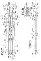
- FIG. 1is an enlarged top plan view of a first embodiment of an electrochemical sensor made in accordance with the teachings of the present invention
- FIG. 2is a sectional end view of the electrochemical sensor of FIG. 1 taken along plane 2 — 2 ;
- FIG. 3is a sectional end view of the electrochemical sensor of FIG. 1 taken along plane 3 — 3 ;
- FIG. 4is a sectional end view of the electrochemical sensor of FIG. 1 taken along plane 4 — 4 ;
- FIG. 5is a sectional end view of the electrochemical sensor of FIG. 1 taken along plane 5 — 5 ;
- FIG. 6is a sectional side view of the electrochemical sensor of FIG. 1 taken along plane 6 — 6 ;
- FIG. 7is an enlarged top plan view of a second embodiment of an electrochemical sensor made in accordance with the teachings of the present invention.
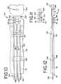
- FIG. 8is an end elevation view of the electrochemical sensor of FIG. 7;
- FIG. 9is a side elevation view of the electrochemical sensor of FIG. 7;
- FIG. 10is a bottom plan view of the electrochemical sensor of FIG. 7;
- FIG. 11is a sectional end view of the electrochemical sensor of FIG. 7 taken along plane 11 — 11 ;
- FIG. 12is a sectional end view of the electrochemical sensor of FIG. 7 taken along plane 12 — 12 ;
- FIG. 13shows an enlarged top plan view of a third embodiment of an electrochemical sensor made in accordance with the teachings of the present invention.
- FIG. 14shows an enlarged bottom plan view of the electrochemical sensor of FIG. 13;
- FIG. 15is a sectional side view of the electrochemical sensor of FIG. 13 taken along plane 15 — 15 ;
- FIG. 16is a sectional end view of the electrochemical sensor of FIG. 13 taken along plane 16 — 16 ;
- FIG. 17shows a top plan view of a third embodiment of an electrochemical sensor made in accordance with the teachings of the present invention.
- FIG. 18shows an enlarged bottom view of the electrochemical sensor of FIG. 17
- FIG. 19shows a sectional side view of the electrochemical sensor of FIG. 17 taken along plan 19 — 19 ;
- FIGS. 20 a, bshow a magnified view of the terminal end portion of the sensor of FIG. 17 having the end cap (a) extended away from the body and (b) secured to the body.
- FIG. 1shows the sensor 10 as though it were made out of clear plastic, permitting one to look inside it.
- the internal components and hidden external componentswould not normally be visible looking down on the sensor 10 .
- This renditionwould be similar to a view taken along plane x—x in FIG. 2 .
- the sensor or test strip of the first embodiment 10includes an injection molded plastic body 12 , opaque or preferably translucent, having a meter attachment end or plug end 14 and a fluid sample receiving end 16 .
- the bodyhas a bottom surface 13 , a top surface 15 and a tapered portion 20 connecting a first top surface 15 a to a second top surface 15 b, the first top surface being lower than the second top surface, and a third top surface 15 c, also lower than the second top surface.
- the body 12contains three spaced apart electrodes 30 , 31 , 32 .
- the plug end 14 of the body 12includes a pair of tapered side edges 18 , 19 and a wedge shaped top portion 20 .
- the tapered side edges 18 , 19facilitate a user inserting the sensor's plug end 14 into the socket cavity of a conventional meter (not shown). Moreover, the wedged portion 20 of the sensor serves as a stop, and frictionally holds the sensor 10 within the socket cavity of the meter.
- the fluid sample receiving end 16 of the sensor 10includes an electrochemical reaction zone 24 adjacent the terminal end 16 of the body.
- This reaction zone 24is a channel formed in the third top surface 15 c and about/adjacent the electrodes 30 , 31 , 32 in the body 12 for analyzing the fluid drawn into the body 12 for a particular analyte. While the reaction zone may be formed above or below the electrodes, the preference has been to construct it above the electrodes.
- An end cap 27is welded [by ultrasonics or adhesive] over the reaction zone 24 and onto the third top surface 15 c. The top of the end cap 27 aligns with the top 15 , 15 b of the body 12 .
- the end cap 27is preferably made of the same material as the molded body 12 and attached thereto by ultrasonic welding or gluing.
- cap 27is shown as a separate piece, it can also be constructed as part of the body 12 and hingeably connected to the body such that it can be pivoted onto the third top surface 15 c and attached [e.g., see The Second Embodiment]. In this manner, the entire sensor can be made at one time and as one molded, unitary piece.
- a capillary opening 28is formed in the terminal end 16 of the sensor 10 when the cap 27 is welded (or folded) to the body 12 .
- This capillary openingleads to the reaction zone 24 .
- the sensor 10is a capillary fill device, that is, the reaction zone 24 is small enough to draw a fluid sample into the zone when the capillary opening or inlet 28 is placed in contact with the fluid being tested, such as a drop of blood. Accordingly, if one wants to test his/her blood, s/he touches the terminal end 16 to the blood and the blood is drawn into the sensor 10 and reaction zone 24 through the capillary opening 28 . This is much easier than placing the sample (such as blood) on the sensor and on a target zone as in the prior art.
- a vent 29is constructed into the cap 27 .
- This ventis in communication with the reaction zone 24 .
- This vent 29releases air pressure as the reaction zone 24 draws and fills with fluid.
- a plurality of electrically conductive leads or electrodes 30 , 31 , 32are encased within the injection molded body 12 .
- the body 12is molded about these leads 30 , 31 , 32 .
- these leadsare spaced from one another. They 30 , 31 , 32 are primarily encased in the body 12 and run from the plug end 14 to the reaction zone 24 , just before the terminal end 16 .
- the leads' 30 , 31 , 32 ends 26are positioned just before the terminal end 16 of the sensor.
- the conductive leads 30 , 31 , 32consist of an electrically conductive material like metal or metal alloy such as platinum, palladium, gold, silver, nickel, nickel-chrome, stainless steel, copper or the like. Moreover, each lead preferably consists of a single wire, or in an alternative preferred embodiment (See The Second Embodiment), a stamped metal member plated with gold or the like. In the first embodiment, the outer leads 30 and 32 are equally spaced from the inner lead 31 with the spacing of the leads at the fluid sample receiving end 16 of the body 12 being closer together than at the meter attachment end 14 .
- Segments 33 of the leads 30 , 31 , 32are exposed about the plug end 14 of the body 12 to provide contact surface areas 34 , 35 , 36 respectively with the meter (not shown).
- the exposed contact surface areas 34 , 35 , 36extend from the tapered top portion 20 of the body 12 to the plug end 14 of the body 12 on or partially embedded into the first top surface 15 a.
- the body 12may be molded such that the segments 33 of the leads 31 , 31 , 32 are embedded (partially molded into the first top surface 15 a ) and held by the body 12 opposite the contact surface areas 34 , 35 , 36 . In this manner, the leads are exposed for contact with the meter and maintained in a position without the use of adhesives or welding.
- the body 12is constructed of an electrically insulating injection moldable plastic.
- Certain structural support componentsare molded within the body 12 of the sensor 10 to hold and maintain the leads 30 , 31 , 32 within the body, in spaced relationship to one another, during and after the molding process.
- guide blocks 42 and alignment pins 44are molded within the body 12 for proper mounting of the leads 30 , 31 , 32 .
- Aperturesare also formed in the top surface 15 and bottom surface 13 of the body 12 for permitting the ingress and egress of fingers into the mold during the molding process (to be discussed below).
- a first aperture 46is molded into the second top surface 15 b and a second aperture 48 and third aperture 50 are formed into the bottom surface 13 of the body 12 .
- each of these apertures 46 , 48 , 50is covered up or sealed with plastic (e.g., the same plastic used in the molding process) or left open.
- plastice.g., the same plastic used in the molding process
- Their 46 , 48 , 50 sizesare relatively small; leaving them open should not cause any safety issues or affect the sensor's ability. Fingers cannot fit into the apertures and debris from the outside will likely be unable to enter the apertures and contact the leads 30 , 31 , 32 .
- one lead 30serves as a primary working electrode 52
- a second lead 31acts as a reference or counter electrode 53
- the third lead 32serves as an auxiliary, secondary or second working electrode 54
- the conductive leads 30 , 31 , 32are the only leads (electrodes) coming into contact with the test sample of fluid entering the sensor 10 .
- the electrodes 52 , 53 , 54are electrically insulated from the rest of the sensor 10 by molded plastic to ensure a signal carried by the leads arises only from that portion exposed to the test sample in the electrochemical reaction zone 24 .
- an enzyme 56is applied to the outer surface of the primary working electrode 52 and, if desired, an electron transfer mediator.
- the enzymecan consist of, for instance, flavo-proteins, pqq-enzymes, haem-containing enzymes, oxidoreductase, or the like.
- mediatorssee U.S. Pat. Nos. 4,545,382 and 4,224,125, the disclosures of which are hereby incorporated by reference.
- an antibody 57can be applied to the outer surface of the secondary working electrode 54 .
- the reaction zone 24can contain antibodies, enzyme-antibody conjugates, enzyme-analyte conjugates, and the like.
- an enzyme 56can also be applied to the second working electrode 54 and an antibody can be applied to the outer surface of the primary working electrode 52 .
- the enzyme 56is specific for the test to be performed by the sensor 10 .
- the working electrode 52or secondary working electrode 54 , or both, can be coated with an enzyme 56 such as glucose oxidase or glucose dehydrogenase formulated to react at different levels or intensities for the measurement of glucose in a human blood sample.
- an enzyme 56such as glucose oxidase or glucose dehydrogenase formulated to react at different levels or intensities for the measurement of glucose in a human blood sample.
- the glucose sensoris used with a meter to measure the electrochemical signal, such as electrical current, arising from oxidation or reduction of the enzymatic turnover product(s). The magnitude of the signal is directly proportional to the glucose concentration or any other compound for which a specific enzyme has been coated on the electrodes.
- the enzyme 56can be applied to the entire exposed surface area of the primary electrode 52 (or secondary electrode 54 ).
- the entire exposed area of the electrodemay not need to be covered with the enzyme as long as a well defined area of the electrode is covered with the enzyme.
- an enzyme 57can be applied to all the electrodes 52 , 53 , 54 in the reaction zone 24 and measures can be taken by a meter.
- one of the working electrodes ( 52 or 54 )is selectively coated with the enzyme 57 carrying a reagent with the enzyme and the other working electrode ( 54 or 52 ) is coated with a reagent lacking the respective enzyme.
- the potential or current between the reference and the electrode without the enzymecan be compared with the potential or current between the reference and the electrode with the enzyme. The measuring and comparing of the potential and current differences are well known to those skilled in the art.
- the senor 10is used in conjunction with a meter capable of measuring an electrical property of the fluid sample after the addition of the fluid sample into the reaction zone 24 .
- the electrical property being measuredmay be, for example, electrical current, electrical potential, electrical charge, or impedance.
- An example of measuring changes in electrical potential to perform an analytical testis illustrated by U.S. Pat. No. 5,413,690, the disclosure of which is hereby incorporated by reference.
- the plug end 14 of the sensor 10can be inserted and connected to a meter, which includes a power source (a battery). Improvements in such meters and a sensor system are found in U.S. Pat. Nos. 4,999,632; 5,243,516; 5,366,609; 5,352,351; 5,405,511; and 5,438,271, the disclosures of which are hereby incorporated by reference.
- analyte-containing fluidscan be analyzed by the electrochemical sensor of the present invention.
- analytes in human and animal body fluidssuch as whole blood, blood serum and plasma, urine and cerebrospinal fluid may all be measured.
- analytes found in fermentation products, food and agricultural products, and in environmental substances, which potentially contain environmental contaminants,may be measured.
- the present inventionmolds the sensors with the conductive elements inside the mold during the molding process.
- the advantagesare many. In addition to making a stronger more durable sensor, such a process reduces labor involvement and steps and produces a more consistent product.
- the moldhas the shape of the body 12 .
- the conductive wires 30 , 31 , 32 for the electrodesare first molded into the product. Specifically, the wire leads are fed into the mold and placed on or between figures [not shown] projecting into the mold through the openings in the mold (corresponding to the apertures 46 , 48 , 50 ) to hold the wires in place and level during the set-up and molding process.
- the bottom aperturespermit the fingers projecting into the mold to support the wires and the top apertures permit the fingers projecting into the mold to hold the wires.
- the liquid plasticis injected into the mold where it fills the mold. The plastic is then cooled.
- the fingersare pulled from and exit the mold through the openings (apertures 46 , 48 , 50 ).
- the molded sensor 12is next ejected from the mold.
- the reagentsare next applied to the electrodes after the molding process is finished.
- the capis treated with a surfactant that facilitates pulling or drawing the fluid (e.g., test blood) into the capillary gap at the end of the sensor.
- the reagentsincluding the enzyme are applied to the electrodes.
- the end cap 27is thereafter connected to the main body 12 and any undesirable openings in the sensor can be sealed closed by the same plastic used for the mold.
- the chemicalscan be applied to the wires after the end cap is married to the body. Any extraneous wire(s) projecting from the sensor can be cut and removed. Then, any desired writings on the sensor (e.g., manufacturing codes, product name, etc.) can then be applied to the sensor by conventional means.
- FIGS. 7-12an electrochemical sensor in accordance with the present invention, second embodiment, is depicted.
- components similar to those in the first embodiment ( 10 )will be identified with the same reference numbers, but in the 100 series.
- FIG. 7shows the sensor 110 as though it were made out of clear plastic, permitting one to look inside it.
- the sensor of the second embodiment 110includes a molded plastic body 112 having a meter attachment end or plug end 114 and a fluid sample receiving end 116 .
- the bodyhas a bottom surface 113 and a top surface 115 .
- An end cap 127is integral to the body 112 and molded with the body.
- a hinge 227permits the pivoting of the end cap onto the main body as will be explained.
- the top surface 115 of the sensor 110has three top surfaces 115 a, 115 b, 115 c.
- the first top surface 115 aruns most of the length of the body and terminates at a ledge 215 ; the second top surface 115 b is positioned below or is lower than the first 115 a; and, the third top surface 115 c is separated from the other two top surfaces 115 a, 115 b by the hinge 227 .
- the end cap 127is rotated about the hinge such that the third top surface 115 c abuts the second top surface 115 b, face-to-face, and rests adjacent the ledge 215 of the top surface 115 a.
- the bottom surface 13 a of the cap 127thus becomes the top surface adjacent the first top surface 115 a. See FIG. 8.
- a pair of tapered protuberances 125 formed in the end cap 127 and a pair of tapered troughs 122 formed in the main body 112align and mate when the cap is folded into place. This facilitates and ensures correct alignment of the hinged parts.
- the body 112contains three spaced apart electrodes 130 , 131 , 132 .
- the plug end 114 of the body 112includes a pair of tapered side edges 118 , 119 to facilitate a user inserting the sensor's plug end 114 into the socket cavity of a conventional meter (not shown).
- the fluid sample receiving end 116 of the sensor 110includes an electrochemical reaction zone 124 adjacent the terminal end 116 of the body.
- This reaction zone 124is a channel formed in the second top surface 115 b and about/adjacent the electrodes 130 , 131 , 132 in the body 112 for reacting with the fluid drawn into the body 112 . While this reaction zone may be formed above or below the electrodes, the preference has been to construct it above the electrodes.
- a ridge 327is formed on the top surface (third top surface 115 c ) of the end cap. This ridge prevents any fluid from leaving the reaction zone 124 or debris from entering the reaction zone once the end cap 127 is welded [by ultrasonics or adhesive] onto the second top surface 115 b.
- An optional channel 327 amay be constructed in the third top surface 115 c to increase the height of the reaction zone 124 .
- a capillary opening 128is formed in the terminal end 116 of the sensor 110 when the cap 127 is folded and welded into place. This capillary opening leads to the reaction zone 124 .
- the width of the opening 128is approximately the same as the length of the sensing electrodes 130 , 131 , 132 exposed to the test fluid in the reaction zone 124 .
- the sensor 110 of the second embodimentis also a capillary fill device, that is, the reaction zone 124 is small enough to draw a fluid sample into the zone when the capillary opening 128 is placed in contact with the fluid being tested.
- a vent 129 provided in the cap 127is in communication with the reaction zone 124 to release pressure as the reaction zone 124 draws and fills with fluid.
- the bottom or base of the capillary inletis flush with the top surface of electrodes 130 , 131 , 132 .
- an electrically conductive plate(stamped or cast) having leads or electrodes 130 , 131 , 132 .
- the body 112is molded around the plate and these leads 130 , 131 , 32 .
- the conductive plateis a single piece of material; it includes the leads 130 , 131 , 132 and connecting segments 230 and 231 . When the sensor is made, the segments are connecting the leads. After molding, the segments 230 , 231 are cut and/or removed so that the leads are distinct and separated from one another. If they were connected, the system would short circuit.
- the electrodes 130 , 131 , 132are primarily encased in the body 112 and run from the plug end 114 into the reaction zone 124 , just before the terminal end 116 .
- the leads 130 , 131 , 132may be widened if desired in the reaction zone to expose more surface area to the fluid and chemicals contacting one another in the zone.
- the leads 130 , 131 , 132can be as wide as the sensing parts.
- These leads 130 , 131 , 132are an electrically conductive material like metal or metal alloy such as platinum, palladium, gold, silver, nickel, nickel-chrome, stainless steel, copper or the like. To enhance their performance and sensitivity, they may also be coated, e.g., made of copper and coated with gold.
- the leads 130 , 131 , 132are spaced from and parallel to one another.
- Segments 133 of the leads 130 , 131 , 132extend outwardly from the body 112 from the plug end 114 of the sensor 110 and are exposed to provide contact surface areas 134 , 135 , 136 respectively with the meter (not shown). These leads can also be embedded in the molded plastic such that their upper surfaces are exposed in portions.
- the portion of the leads 130 , 131 , 132 between the sensor plug end 114 and the fluid sample receiving end 116are embedded, or encased, within the plastic injection molded body 112 ; the body 112 is constructed of an electrically insulating injection moldable plastic.
- Aperturesare formed in the top surface 115 and bottom surface 113 of the body 112 for permitting the ingress and egress of fingers into the mold during the molding process.
- a set ( 3 ) of first apertures 146 and a set ( 3 ) of second apertures 147are molded into the top surface 15 a;
- a third aperture 148 and fourth aperture 150 and a set ( 3 ) of fifth apertures 160 , 161 , 162are formed into the bottom surface 113 of the body 112 .
- one outer lead 130serves as a primary working electrode 152
- the center lead 131acts as a reference or counter electrode 153
- the other outer lead 132serves as an auxiliary or secondary or second working electrode 154 .
- These conductive leads 130 , 131 , 132are the only leads (electrodes) coming into contact with the test sample of fluid entering the sensor 110 .
- the electrodes 152 , 153 , 154are electrically insulated from the rest of the sensor 110 by molded plastic to ensure a signal carried by the leads arises only from that portion exposed to the test sample in the electrochemical reaction zone 124 .
- an enzyme 156is applied to the outer surface of the primary working electrode 152 and, if desired, an electron transfer mediator.
- An antibody 157may also be applied to the outer surface of the secondary working electrode 154 .
- An enzyme 156can also be applied the second working electrode 154 and an antibody to the outer surface of the primary working electrode 52 .
- the enzyme 156can be applied to the entire exposed surface area of the primary electrode 152 (or secondary electrode 154 ). Alternatively, the entire exposed area of the electrode may not need to be covered with the enzyme as long as a well defined area of the electrode is covered with the enzyme. Or, an enzyme can be applied to all the electrodes 152 , 153 , 154 in the reaction zone 124 and measurements can be taken by a meter. Preferably, one of the working electrodes ( 152 or 154 ) is selectively coated with the enzyme carrying a reagent with the enzyme and the other working electrode ( 154 or 152 ) is coated with a reagent lacking the respective enzyme.
- the sensor 110is used in conjunction with a meter capable of measuring an electrical property of the fluid sample after the addition of the fluid sample into the reaction zone 124 .
- the plug end 114 of the sensor 110is inserted and connected to a meter, as before with the first embodiment.
- the moldhas the shape of the body 112 .
- the conductive 130 , 131 , 132 leads/electrodes(in the form of a plate with the joining extensions 230 , 231 for the electrodes) are first treated with any coatings (metal).
- the chemicals/reagentsmay also be applied before molding; or, they can be applied after the molding.
- the plateis fed into the mold and placed on or between fingers (not shown) projecting into the mold through the openings in the mold (corresponding to the apertures 146 , 147 , 148 , 150 ) to hold the plate in place and level during the set-up and molding process.
- Knives or punchesare also inserted through the top surface of the mold (outline of opening formed by the knives/punches 170 ). These knives punch and sever the jointing extensions 230 , 231 and hold the bent portions in place during molding (see FIG. 11 ). As before, the bottom apertures permit the fingers projecting into the mold to support the plate with leads and the top apertures permit the fingers projecting into the mold to hold the plate and leads.
- the liquid plasticis injected into the mold where it fills the mold. The plastic is then cooled.
- the fingersare drawn from the mold through the openings (apertures 146 , 147 , 148 , 150 , 160 , 161 , 162 ).
- the knives/punchesare drawn through the upper surface openings 170 .
- the cut or skived extensions 230 , 231 disposed between the leads 130 , 131 and 131 , 132ensures the leads are kept separate.
- the molded sensor 112is then ejected from the mold and any undesirable openings in the sensor can be sealed closed by the same plastic used for the mold.
- the critical reagentsare applied to the sensors in the reaction zone 124 above the leads.
- a surfactantcan be used to treat the capillary inlet to facilitate the capillary function. Any extraneous metal projecting from the sensor can be cut and removed. Then, any desired writings on the sensor (e.g., manufacturing codes, product name, etc.) can then be applied to the sensors by conventional means.
- FIGS. 13-20Shown in FIGS. 13-20 is a third embodiment of an electrochemical sensor in accordance with the present invention. These figures use the same reference numbers, but in the 300 series, to identify components that are similar to those in the previous embodiments.
- sensor 310 , 310 ′is used in conjunction with a meter capable of measuring an electrochemical property of the fluid sample after the fluid sample is drawn into the reaction zone 324 , 324 ′.
- the sensor 310 , 310 ′includes a molded plastic body 312 , 312 ′ having a meter attachment end or plug end 314 , 314 ′ and a fluid sample receiving end 316 , 316 ′.
- the plug end 314 , 314 ′is insertable or connectable to a meter, as with the two prior embodiments.
- the bodyalso has a bottom surface 313 , 313 ′ and a top surface 315 , 315 ′.
- the body 312 , 312 ′is molded as a unitary, single piece having two portions—(a) an electrode-encasing housing 317 , 317 ′ and (b) an end cap 327 , 327 ′ pivotably attached to the electrode housing 317 , 317 ′ at the fluid sample receiving end 316 , 316 ′ at hinge 427 , 427 ′.
- the electrode housing and the end capmay be separate pieces that are securedly attachable to one another.
- the side edges 318 , 319 , 318 ′, 319 ′ near the plug end 314 , 314 ′ of the body 312 , 312 ′are tapered so the plug end 314 , 314 ′ inserts more easily into the socket cavity of a conventional meter (not shown).
- the end cap 327 , 327 ′may have a “notch” 326 , 326 ′ formed into the outermost edge opposite the body to facilitate molding.
- FIG. 15shows a longitudinal sectional side view of sensor 310 .
- the top surface 315has three sections or surfaces including 315 a, 315 b, 315 c.
- the first top surface 315 aaccounts for a predominate portion of the body, as it extends from the plug end 314 to a ledge 415 .
- the second top surface 315 bruns from the ledge 415 to the hinge 427 , on a plane lower than 315 a.
- the third top surface 315 cextends across one surface of the end cap 327 , from the hinge 427 to the outermost edge of the end cap.
- the hinge 427allows the end cap to be folded onto the body so that the third top surface 315 c abuts the second top surface 315 b, face-to-face, and the edge of the end cap rests substantially adjacent the ledge 415 , as in the second embodiment discussed above.
- the bottom surface 313 a of the end cap 327becomes part of the top surface of the body and rests adjacent the first top surface 315 a, in essentially the same plane, as shown in FIG. 15 .
- the end capWhen the end cap is folded onto the second top surface 315 b of the body, adjacent the terminal end 316 of the body, a channel termed the “electrochemical reaction zone” 324 forms in the body.
- the reaction zone 324is bound on one side by the second top surface 315 b and, on the opposite side, by top surface of the end cap 327 .
- the reaction zonehas a volume defined by the shape of the body.
- the capmay be shaped so that when it is pivoted onto the body, the cap defines the volume of the reaction zone; or the shape of both the cap and the body may form the volume of the reaction zone.
- FIGS. 17-19show a sensor in accordance with the invention having two electrodes 330 ′, 331 ′.
- the leadsare not entirely embedded in the insulative material of the body.
- at least a portion of the leadse.g., the tips, sides, or other portion—is exposed therein as sensing electrodes 330 , 331 , 332 for contacting fluid sample drawn into the body 312 .
- the reaction zone 324lies primarily in the bottom lengthwise portion of the detector. Although the reaction zone may be formed above or below the electrodes, it is preferably constructed below the electrodes.
- the cap 327is folded onto the body and securedly affixed to the body to form a substantially tight seal.
- a capillary opening 328forms in the terminal end 316 of the sensor 310 .
- the capillary opening 328leads to the reaction zone 324 where the edges of the sensing electrodes 330 , 331 , 332 are exposed to the test fluid.
- the width of the capillary opening 328is approximately the same as that of the sensing electrodes 330 , 331 , 332 .
- Body 312may also have proturberances to ensure correct alignment of the surfaces when folded about the hinge.
- the protuberancesare typically disposed on at least one of (a) the surface of the end cap that folds onto the body and (b) the top third surface of the body onto which the end cap folds that is covered by the end cap when folded onto the body.
- the protuberancesmay appear on both the end cap and the upper surface 315 b of the body.
- the protuberancecomprises a ridge 527 and a recessed surface 528 that mate when the cap is folded onto the body, to form the reaction zone.
- the ridge 527may be formed on the second top surface 315 b along the periphery of the reaction zone 324 , and the recessed surface may be formed on the cap 327 , or vice versa.
- the ridge 527may also sit in and be substantially aligned with a secondary ridge (not shown), which increases the height of ridge 527 .
- the ridge 527mates with recessed surface 528 to form a seal, enclosing the reaction zone 324 within the body.
- the ridge 527 and recessed surface 528may be further welded together by, e.g., ultrasonic energy, adhesive, or any other suitable techniques.
- the seal, so formedprevents the reaction zone 324 from losing fluid or accepting debris.
- the ridge 527fuses into the recessed surface 528 without affecting the performance of the sensor.
- the proturberanceis an energy director 529 ′ formed on at least one of the end cap and the upper surface 315 b ′ of the body.
- the energy director 529 ′typically comprises at least one protruding ridge extending preferably along the periphery of the end cap.
- the energy directorextends along the three unattached sides of the end cap, although it may extend across portions of the sides.
- the energy director 529 ′begins at hinge 427 ′ and extends on the end cap 327 ′ directionally away from the hinge 427 ′ and across the end farthest from the hinge.
- the energy director 529 ′When the cap is pivoted onto the body, the energy director 529 ′ is generally melted by, e.g., ultrasonic energy or other conventional means, to induce formation of a strong, leak-free joint bond between the bottom surface and cap surface.
- the bondso formed seals the fluid within the chamber, preventing fluid from diffusing out from the reaction zone.
- a sealmay be formed by the application of adhesives.
- the sensor of the third embodimentis also a capillary fill device; i.e., when the capillary opening 328 ′ is placed in contact with the fluid being tested, the reaction zone 324 ′ draws the fluid sample into the zone.
- sample fill vent 368 ′Included in cap 327 ′ is sample fill vent 368 ′.
- cap 327 ′is folded onto body 312 ′, at least a portion of the sample fill vent 368 ′ is in communication with the reaction zone to form a depressurization vent 378 ′ for releasing air from the reaction zone as the zone fills with fluid.
- the depressurization vent 378 ′extends between one edge of the sample fill vent 368 ′ and the ledge 415 ′ of the reaction zone, which is the back wall of the reaction zone farthest from the terminal end 316 ′.
- FIGS. 20 a, bshow a magnified view of the terminal end portion of the sensor 310 ′ of FIG. 17 .
- FIG. 20 ashows the cap 327 ′ extended away from the body
- FIG. 20 bshows the cap 327 ′ folded onto the body of the sensor.
- the depressurization vent 378 ′provides for fill detection in the third embodiment.
- Fluid drawn through the capillary opening 328 ′travels along the capillary, preferably in the lower portion of the body 312 ′, to the reaction zone 324 ′ where it contacts the electrodes 331 ′, 332 ′ of sensor 310 ′ (or electrodes 330 , 331 , 332 of sensor 330 , 331 , 332 ).
- the surface of the electrodes facing the upper surface 315 ′ of the bodyis flush with the bottom periphery of the capillary inlet 328 ′.
- sample fluidAs sample fluid enters the reaction zone 324 ′, it travels toward the end of the reaction zone farthest from the capillary inlet until it reaches the depressurization vent 378 ′. As the fluid displaces air present in the depressurization vent 378 ′, the fluid contacts at least one of the electrodes in the reaction zone, so as to close an open circuit in the sensor 310 ′ and cause current to flow through the sensor. The flow of current in the sensor activates the meter, signaling that the capillary chamber or reaction zone is sufficiently filled with fluid.
- the depressurization vent 378 ′may also be used to visually detect fluid fill in the reaction zone.
- the injection molded body 312is constructed of an electrically insulating injection moldable plastic.
- the body 312is molded around the electrically conductive plate (stamped or cast) with its leads 330 , 331 , 332 so that the conductive plate is encased primarily within the body 312 .
- the conductive plateis a single piece of material; it includes the leads 330 , 331 , 332 ( 330 ′, 331 ′ in FIG. 18) and the connecting segments 430 and 431 (reference no. 432 in sensor 310 ′). After the sensor is made, the segments 430 and 431 interconnecting the leads are cut and/or removed to separate the leads from one another. If the interconnecting segments remained intact during operation of the sensor, the system would short circuit.
- the bodymay have a plurality of guides molded therein with at least one of the guides abutting against at least one of the leads.
- the leads 330 , 331 , 332extend longitudinally through the body 312 from the plug end 314 to the reaction zone 324 , terminating just before the terminal end 316 .
- the leads 330 , 331 , 332are encased, or embedded, in the body 312 at a pre-determined distance from each other; they are generally parallel to one another though this is not necessary for operation of the sensor.
- a sufficient portion of the leadsare exposed for contacting the fluid sample; the exposed portion includes, e.g., at least the tips, ends, or sides of the electrodes.
- the electrodes 330 , 331 , 332are an electrically conductive material such as metal or metal alloy; e.g., platinum, palladium, gold, silver, nickel, nickel-chrome, stainless steel, copper or the like. For enhanced performance and sensitivity, they may also be coated with a metal different from that composing the lead; e.g., a lead made of copper may be coated with gold. If desired, the width of the leads 330 , 331 , 332 may be widened or narrowed in the reaction zone 324 to expose more or less surface area to the fluid and chemicals therein.
- the leads 330 , 331 , 332 extending through the bodycan be as wide as the exposed portion within the reaction zone, which comprises the electrodes 330 , 331 , 332 .
- Each of the leads 330 , 331 , 332terminates in a segment 333 a,b,c that may extend outside the body 312 from the plug end 314 where the leads provide surface areas 334 , 335 , 336 , respectively, for contact with the meter (not shown).
- the leadscan be embedded in the molded plastic such that only a portion of each lead is exposed outside the body at the plug end 314 ; or the top surface of the leads comes in contact with the meter electrical contact leads.
- Apertures molded into the top surface 315 and the bottom surface 113 of the body 312permit fingers to be inserted into and removed from the mold during the molding process.
- the top surface 315 ahas two sets of apertures—first apertures 346 and second apertures 347 —each having three individual openings or apertures.
- the bottom surface 313has third aperture 348 , fourth aperture 350 , and fifth apertures, the latter including three individual apertures 360 , 361 , 362 .
- each of these apertures 346 , 347 , 348 , 350is preferably left open.
- the aperturesare closed to prevent accidental contact of the fluid with areas other than the electrodes in the reaction zone.
- the aperturesmay, alternatively, be covered such as with the same or a different material used in the molding process.
- conductive electrodes 330 , 331 , 332include a primary working electrode 352 , a reference or counter electrode 353 , and a secondary working electrode 354 .
- the conductive electrodes 330 , 331 , 332contact the test sample, in fluid form, as it enters the sensor 310 .
- the signal carried by the electrodesarises in the reaction zone 324 from contact made by the exposed portion of the electrode with the test sample.
- one electrodepreferably the center electrode is a reference electrode.
- the reaction zonemay also have one or, alternatively, two working electrodes; e.g., primary working electrode 352 and secondary electrode 354 .
- an enzyme, conjugated to another moiety, such as an antibody or antigen or an analyte,is applied to the outer surface of the primary working electrode 352 , and if desired, an electron transfer mediator may be applied to the same electrode 352 .
- An antibodymay also be applied to the outer surface of the secondary working electrode 354 or otherwise present in the reaction zone.
- the reaction zone 324can contain antibodies, enzyme-antibody conjugates, enzyme-analyte conjugates, and the like.
- the enzymecan be applied to the entire exposed surface of the primary electrode 352 or the secondary electrode 354 .
- the enzymeis applied to a particular, defined portion of a working electrode.
- an enzymecan be applied to all the electrodes 352 , 353 , 354 in the reaction zone 324 .
- one of the working electrodes ( 352 or 354 )is selectively coated with the enzyme carrying a reagent with the enzyme, and the other working electrode ( 354 or 352 ) is coated with a reagent lacking the respective enzyme.
- the reaction zone or cavity 324may itself be coated with a substance—such as a reagent, an antibody, or an enzyme—that reacts with certain constituents in the fluid sample to change the electrochemical properties of the sample. The resulting change is readily detected by the electrodes and measured by the meter.
- a substancesuch as a reagent, an antibody, or an enzyme
- the moldhas the shape of the body 312 .
- the conductive 330 , 331 , 332 leads(in the form of a composite plate with the joining extensions 430 , 431 for interconnecting the electrodes) are first treated or coated with a substance, which may be an enzyme, an antibody, or a chemical reagent, as examples.
- the chemicals/reagents(with and without enzymes) are generally applied after the molding.
- the plateis fed into the mold and placed on or between fingers (not shown) that project into the mold through the openings in the mold, which correspond to the apertures 346 , 347 , 348 , 350 , 360 , 361 , 362 .
- the fingershold the plate in place, keeping it level during the set-up and molding process.
- Knives or punchesare inserted through the top surface of the mold (outline of opening formed by the knives/punches 370 ). These knives punch and sever the joining extensions 430 , 431 and hold the bent portions in place during molding, as shown in FIG. 15 .
- the bottom aperturesallow the fingers to be projected into the mold to support the plate with leads; similarly, the top apertures allow the fingers to be projected into the mold to hold the plate in place with the leads.
- Liquid plasticis injected into the mold, filling it. The plastic is then cooled.
- the fingersare removed from the mold through the openings; i.e., apertures 346 , 347 , 348 , 350 , 360 , 361 , 362 .
- the knives/punchesare drawn through and removed from the upper surface openings 370 , leaving the cut or skived extensions 430 , 431 disposed between the leads 330 , 331 and 331 , 332 . These cut extension keep the leads separated.
- the molded sensor 312is then ejected from the mold, and any undesirable openings in the sensor can be sealed closed with the same plastic used for the mold.
- the critical reagentsare applied to the sensor in the reaction zone 324 above the leads.
- a surfactantcan also be applied to the capillary opening 328 to facilitate the capillary function. Any extraneous metal projecting from the sensor can be cut and removed.
- any desired writings or other designations on the sensore.g., manufacturing codes, product name, etc. can be applied to the sensors by conventional means.
- a sensoris designed for use with a light reflectance measuring meter for photometric detection of a dye contained within a fluid sample receiving well.
Landscapes
- Life Sciences & Earth Sciences (AREA)
- Health & Medical Sciences (AREA)
- Chemical & Material Sciences (AREA)
- Physics & Mathematics (AREA)
- Biochemistry (AREA)
- Hematology (AREA)
- Chemical Kinetics & Catalysis (AREA)
- Electrochemistry (AREA)
- Biophysics (AREA)
- Analytical Chemistry (AREA)
- Molecular Biology (AREA)
- General Health & Medical Sciences (AREA)
- General Physics & Mathematics (AREA)
- Immunology (AREA)
- Pathology (AREA)
- Measurement Of The Respiration, Hearing Ability, Form, And Blood Characteristics Of Living Organisms (AREA)
- Apparatus Associated With Microorganisms And Enzymes (AREA)
- Investigating Or Analysing Biological Materials (AREA)
- Immobilizing And Processing Of Enzymes And Microorganisms (AREA)
Abstract
Description
Claims (62)
Priority Applications (12)
| Application Number | Priority Date | Filing Date | Title |
|---|---|---|---|
| US10/017,751US6572745B2 (en) | 2001-03-23 | 2001-12-07 | Electrochemical sensor and method thereof |
| CNB02808201XACN100380116C (en) | 2001-03-23 | 2002-03-22 | Electrochemical sensor and method thereof |
| AU2002248674AAU2002248674A1 (en) | 2001-03-23 | 2002-03-22 | Electrochemical sensor and method thereof |
| MXPA03008609AMXPA03008609A (en) | 2001-12-07 | 2002-03-22 | Electrochemical sensor and method thereof. |
| PCT/US2002/008703WO2002077606A2 (en) | 2001-03-23 | 2002-03-22 | Electrochemical sensor and method thereof |
| EP02717688AEP1379861A4 (en) | 2001-03-23 | 2002-03-22 | Electrochemical sensor and method thereof |
| BR0208343-4ABR0208343A (en) | 2001-03-23 | 2002-03-22 | Electrochemical sensor and process for its production |
| CA002442017ACA2442017A1 (en) | 2001-03-23 | 2002-03-22 | Electrochemical sensor and method thereof |
| JP2002575610AJP2005503536A (en) | 2001-03-23 | 2002-03-22 | Electrochemical sensor and method thereof |
| US10/419,581US6849216B2 (en) | 2001-03-23 | 2003-04-21 | Method of making sensor |
| US10/419,503US20030201178A1 (en) | 2001-03-23 | 2003-04-21 | Electrochemical sensor |
| US10/993,317US20050067737A1 (en) | 2001-03-23 | 2004-11-19 | Method of making sensor |
Applications Claiming Priority (2)
| Application Number | Priority Date | Filing Date | Title |
|---|---|---|---|
| US09/820,372US6576102B1 (en) | 2001-03-23 | 2001-03-23 | Electrochemical sensor and method thereof |
| US10/017,751US6572745B2 (en) | 2001-03-23 | 2001-12-07 | Electrochemical sensor and method thereof |
Related Parent Applications (1)
| Application Number | Title | Priority Date | Filing Date |
|---|---|---|---|
| US09/820,372Continuation-In-PartUS6576102B1 (en) | 2001-03-23 | 2001-03-23 | Electrochemical sensor and method thereof |
Related Child Applications (2)
| Application Number | Title | Priority Date | Filing Date |
|---|---|---|---|
| US10/419,503ContinuationUS20030201178A1 (en) | 2001-03-23 | 2003-04-21 | Electrochemical sensor |
| US10/419,581DivisionUS6849216B2 (en) | 2001-03-23 | 2003-04-21 | Method of making sensor |
Publications (2)
| Publication Number | Publication Date |
|---|---|
| US20020157947A1 US20020157947A1 (en) | 2002-10-31 |
| US6572745B2true US6572745B2 (en) | 2003-06-03 |
Family
ID=26690266
Family Applications (4)
| Application Number | Title | Priority Date | Filing Date |
|---|---|---|---|
| US10/017,751Expired - LifetimeUS6572745B2 (en) | 2001-03-23 | 2001-12-07 | Electrochemical sensor and method thereof |
| US10/419,581Expired - LifetimeUS6849216B2 (en) | 2001-03-23 | 2003-04-21 | Method of making sensor |
| US10/419,503AbandonedUS20030201178A1 (en) | 2001-03-23 | 2003-04-21 | Electrochemical sensor |
| US10/993,317AbandonedUS20050067737A1 (en) | 2001-03-23 | 2004-11-19 | Method of making sensor |
Family Applications After (3)
| Application Number | Title | Priority Date | Filing Date |
|---|---|---|---|
| US10/419,581Expired - LifetimeUS6849216B2 (en) | 2001-03-23 | 2003-04-21 | Method of making sensor |
| US10/419,503AbandonedUS20030201178A1 (en) | 2001-03-23 | 2003-04-21 | Electrochemical sensor |
| US10/993,317AbandonedUS20050067737A1 (en) | 2001-03-23 | 2004-11-19 | Method of making sensor |
Country Status (8)
| Country | Link |
|---|---|
| US (4) | US6572745B2 (en) |
| EP (1) | EP1379861A4 (en) |
| JP (1) | JP2005503536A (en) |
| CN (1) | CN100380116C (en) |
| AU (1) | AU2002248674A1 (en) |
| BR (1) | BR0208343A (en) |
| CA (1) | CA2442017A1 (en) |
| WO (1) | WO2002077606A2 (en) |
Cited By (23)
| Publication number | Priority date | Publication date | Assignee | Title |
|---|---|---|---|---|
| US20030201178A1 (en)* | 2001-03-23 | 2003-10-30 | Craig Rappin | Electrochemical sensor |
| US20040094433A1 (en)* | 2002-04-25 | 2004-05-20 | Home Diagnostics, Inc. | Systems and methods for blood glucose sensing |
| US20040149578A1 (en)* | 2003-01-30 | 2004-08-05 | Chun-Mu Huang | Method for manufacturing electrochemical sensor and structure thereof |
| US20050125162A1 (en)* | 2003-12-03 | 2005-06-09 | Kiamars Hajizadeh | Multi-sensor device for motorized meter and methods thereof |
| US20050266571A1 (en)* | 2004-03-26 | 2005-12-01 | Phil Stout | Method for feedback control of a microfluidic system |
| USD512512S1 (en)* | 2003-05-21 | 2005-12-06 | Wachovia Bank, National Association | Blood glucose test strip |
| US20060013731A1 (en)* | 2004-03-26 | 2006-01-19 | Phil Stout | Microfluidic system with feedback control |
| US20060042943A1 (en)* | 2002-12-02 | 2006-03-02 | Arkray, Inc. | Analysis instrument |
| USD531321S1 (en)* | 2005-04-10 | 2006-10-31 | Akubio Limited | Cartridge |
| US20070068807A1 (en)* | 2005-09-27 | 2007-03-29 | Abbott Diabetes Care, Inc. | In vitro analyte sensor and methods of use |
| USD540953S1 (en)* | 2005-05-04 | 2007-04-17 | Metrika, Inc. | Test meter cartridge |
| US20070227911A1 (en)* | 2006-03-29 | 2007-10-04 | Yi Wang | Analyte sensors and methods of use |
| US20080112852A1 (en)* | 2002-04-25 | 2008-05-15 | Neel Gary T | Test Strips and System for Measuring Analyte Levels in a Fluid Sample |
| US20080241962A1 (en)* | 2006-04-04 | 2008-10-02 | Yunlong Wang | Micromachined Diagnostic Device with Controlled Flow of Fluid and Reaction |
| US20090134166A1 (en)* | 2003-04-30 | 2009-05-28 | Inergy Automotive Systems Research | Additive tank for fuel system and production method thereof |
| US20090163790A1 (en)* | 2004-07-13 | 2009-06-25 | Dexcom, Inc. | Transcutaneous analyte sensor |
| US7674615B2 (en) | 2004-05-04 | 2010-03-09 | Bayer Healthcare Llc | Mechanical cartridge with test strip fluid control features for use in a fluid analyte meter |
| US8615282B2 (en) | 2004-07-13 | 2013-12-24 | Dexcom, Inc. | Analyte sensor |
| US8792955B2 (en) | 2004-05-03 | 2014-07-29 | Dexcom, Inc. | Transcutaneous analyte sensor |
| US9247900B2 (en) | 2004-07-13 | 2016-02-02 | Dexcom, Inc. | Analyte sensor |
| US9986942B2 (en) | 2004-07-13 | 2018-06-05 | Dexcom, Inc. | Analyte sensor |
| US20180177644A1 (en)* | 2016-12-22 | 2018-06-28 | Raja Singh Tuli | Diaper Attachment Pod |
| US10610136B2 (en) | 2005-03-10 | 2020-04-07 | Dexcom, Inc. | System and methods for processing analyte sensor data for sensor calibration |
Families Citing this family (102)
| Publication number | Priority date | Publication date | Assignee | Title |
|---|---|---|---|---|
| US6036924A (en) | 1997-12-04 | 2000-03-14 | Hewlett-Packard Company | Cassette of lancet cartridges for sampling blood |
| US6391005B1 (en) | 1998-03-30 | 2002-05-21 | Agilent Technologies, Inc. | Apparatus and method for penetration with shaft having a sensor for sensing penetration depth |
| US8641644B2 (en) | 2000-11-21 | 2014-02-04 | Sanofi-Aventis Deutschland Gmbh | Blood testing apparatus having a rotatable cartridge with multiple lancing elements and testing means |
| DE10057832C1 (en) | 2000-11-21 | 2002-02-21 | Hartmann Paul Ag | Blood analysis device has syringe mounted in casing, annular mounting carrying needles mounted behind test strip and being swiveled so that needle can be pushed through strip and aperture in casing to take blood sample |
| US9427532B2 (en) | 2001-06-12 | 2016-08-30 | Sanofi-Aventis Deutschland Gmbh | Tissue penetration device |
| US7344507B2 (en) | 2002-04-19 | 2008-03-18 | Pelikan Technologies, Inc. | Method and apparatus for lancet actuation |
| WO2002101359A2 (en) | 2001-06-12 | 2002-12-19 | Pelikan Technologies, Inc. | Integrated blood sampling analysis system with multi-use sampling module |
| US9795747B2 (en) | 2010-06-02 | 2017-10-24 | Sanofi-Aventis Deutschland Gmbh | Methods and apparatus for lancet actuation |
| AU2002344825A1 (en) | 2001-06-12 | 2002-12-23 | Pelikan Technologies, Inc. | Method and apparatus for improving success rate of blood yield from a fingerstick |
| JP4272051B2 (en) | 2001-06-12 | 2009-06-03 | ペリカン テクノロジーズ インコーポレイテッド | Blood sampling apparatus and method |
| US8337419B2 (en) | 2002-04-19 | 2012-12-25 | Sanofi-Aventis Deutschland Gmbh | Tissue penetration device |
| US7749174B2 (en) | 2001-06-12 | 2010-07-06 | Pelikan Technologies, Inc. | Method and apparatus for lancet launching device intergrated onto a blood-sampling cartridge |
| JP4209767B2 (en) | 2001-06-12 | 2009-01-14 | ペリカン テクノロジーズ インコーポレイテッド | Self-optimized cutting instrument with adaptive means for temporary changes in skin properties |
| EP1395185B1 (en) | 2001-06-12 | 2010-10-27 | Pelikan Technologies Inc. | Electric lancet actuator |
| US7981056B2 (en)* | 2002-04-19 | 2011-07-19 | Pelikan Technologies, Inc. | Methods and apparatus for lancet actuation |
| US9226699B2 (en) | 2002-04-19 | 2016-01-05 | Sanofi-Aventis Deutschland Gmbh | Body fluid sampling module with a continuous compression tissue interface surface |
| US7041068B2 (en) | 2001-06-12 | 2006-05-09 | Pelikan Technologies, Inc. | Sampling module device and method |
| US7344894B2 (en) | 2001-10-16 | 2008-03-18 | Agilent Technologies, Inc. | Thermal regulation of fluidic samples within a diagnostic cartridge |
| US7674232B2 (en) | 2002-04-19 | 2010-03-09 | Pelikan Technologies, Inc. | Method and apparatus for penetrating tissue |
| US7485128B2 (en) | 2002-04-19 | 2009-02-03 | Pelikan Technologies, Inc. | Method and apparatus for penetrating tissue |
| US7232451B2 (en) | 2002-04-19 | 2007-06-19 | Pelikan Technologies, Inc. | Method and apparatus for penetrating tissue |
| US7244265B2 (en) | 2002-04-19 | 2007-07-17 | Pelikan Technologies, Inc. | Method and apparatus for penetrating tissue |
| US7976476B2 (en) | 2002-04-19 | 2011-07-12 | Pelikan Technologies, Inc. | Device and method for variable speed lancet |
| US9248267B2 (en) | 2002-04-19 | 2016-02-02 | Sanofi-Aventis Deustchland Gmbh | Tissue penetration device |
| US7648468B2 (en)* | 2002-04-19 | 2010-01-19 | Pelikon Technologies, Inc. | Method and apparatus for penetrating tissue |
| US7291117B2 (en) | 2002-04-19 | 2007-11-06 | Pelikan Technologies, Inc. | Method and apparatus for penetrating tissue |
| US7297122B2 (en) | 2002-04-19 | 2007-11-20 | Pelikan Technologies, Inc. | Method and apparatus for penetrating tissue |
| US7410468B2 (en) | 2002-04-19 | 2008-08-12 | Pelikan Technologies, Inc. | Method and apparatus for penetrating tissue |
| US7491178B2 (en) | 2002-04-19 | 2009-02-17 | Pelikan Technologies, Inc. | Method and apparatus for penetrating tissue |
| WO2003088824A2 (en) | 2002-04-19 | 2003-10-30 | Pelikan Technologies, Inc. | Device and method for variable speed lancet |
| US7371247B2 (en) | 2002-04-19 | 2008-05-13 | Pelikan Technologies, Inc | Method and apparatus for penetrating tissue |
| US7717863B2 (en) | 2002-04-19 | 2010-05-18 | Pelikan Technologies, Inc. | Method and apparatus for penetrating tissue |
| US8702624B2 (en) | 2006-09-29 | 2014-04-22 | Sanofi-Aventis Deutschland Gmbh | Analyte measurement device with a single shot actuator |
| US8267870B2 (en) | 2002-04-19 | 2012-09-18 | Sanofi-Aventis Deutschland Gmbh | Method and apparatus for body fluid sampling with hybrid actuation |
| US8221334B2 (en) | 2002-04-19 | 2012-07-17 | Sanofi-Aventis Deutschland Gmbh | Method and apparatus for penetrating tissue |
| US7582099B2 (en) | 2002-04-19 | 2009-09-01 | Pelikan Technologies, Inc | Method and apparatus for penetrating tissue |
| US8360992B2 (en) | 2002-04-19 | 2013-01-29 | Sanofi-Aventis Deutschland Gmbh | Method and apparatus for penetrating tissue |
| US7331931B2 (en) | 2002-04-19 | 2008-02-19 | Pelikan Technologies, Inc. | Method and apparatus for penetrating tissue |
| US7229458B2 (en) | 2002-04-19 | 2007-06-12 | Pelikan Technologies, Inc. | Method and apparatus for penetrating tissue |
| US7524293B2 (en) | 2002-04-19 | 2009-04-28 | Pelikan Technologies, Inc. | Method and apparatus for penetrating tissue |
| US7563232B2 (en) | 2002-04-19 | 2009-07-21 | Pelikan Technologies, Inc. | Method and apparatus for penetrating tissue |
| US7901362B2 (en) | 2002-04-19 | 2011-03-08 | Pelikan Technologies, Inc. | Method and apparatus for penetrating tissue |
| US7547287B2 (en) | 2002-04-19 | 2009-06-16 | Pelikan Technologies, Inc. | Method and apparatus for penetrating tissue |
| US7909778B2 (en)* | 2002-04-19 | 2011-03-22 | Pelikan Technologies, Inc. | Method and apparatus for penetrating tissue |
| US8372016B2 (en) | 2002-04-19 | 2013-02-12 | Sanofi-Aventis Deutschland Gmbh | Method and apparatus for body fluid sampling and analyte sensing |
| US7374544B2 (en) | 2002-04-19 | 2008-05-20 | Pelikan Technologies, Inc. | Method and apparatus for penetrating tissue |
| US7892183B2 (en) | 2002-04-19 | 2011-02-22 | Pelikan Technologies, Inc. | Method and apparatus for body fluid sampling and analyte sensing |
| US9314194B2 (en) | 2002-04-19 | 2016-04-19 | Sanofi-Aventis Deutschland Gmbh | Tissue penetration device |
| US8579831B2 (en) | 2002-04-19 | 2013-11-12 | Sanofi-Aventis Deutschland Gmbh | Method and apparatus for penetrating tissue |
| US7141058B2 (en) | 2002-04-19 | 2006-11-28 | Pelikan Technologies, Inc. | Method and apparatus for a body fluid sampling device using illumination |
| US7708701B2 (en) | 2002-04-19 | 2010-05-04 | Pelikan Technologies, Inc. | Method and apparatus for a multi-use body fluid sampling device |
| US8784335B2 (en) | 2002-04-19 | 2014-07-22 | Sanofi-Aventis Deutschland Gmbh | Body fluid sampling device with a capacitive sensor |
| US7481776B2 (en) | 2002-04-19 | 2009-01-27 | Pelikan Technologies, Inc. | Method and apparatus for penetrating tissue |
| US9795334B2 (en) | 2002-04-19 | 2017-10-24 | Sanofi-Aventis Deutschland Gmbh | Method and apparatus for penetrating tissue |
| US6964871B2 (en) | 2002-04-25 | 2005-11-15 | Home Diagnostics, Inc. | Systems and methods for blood glucose sensing |
| US6946299B2 (en)* | 2002-04-25 | 2005-09-20 | Home Diagnostics, Inc. | Systems and methods for blood glucose sensing |
| US20040099531A1 (en)* | 2002-08-15 | 2004-05-27 | Rengaswamy Srinivasan | Methods and apparatus for electrochemically testing samples for constituents |
| US7265881B2 (en)* | 2002-12-20 | 2007-09-04 | Hewlett-Packard Development Company, L.P. | Method and apparatus for measuring assembly and alignment errors in sensor assemblies |
| US8574895B2 (en) | 2002-12-30 | 2013-11-05 | Sanofi-Aventis Deutschland Gmbh | Method and apparatus using optical techniques to measure analyte levels |
| US7144485B2 (en)* | 2003-01-13 | 2006-12-05 | Hmd Biomedical Inc. | Strips for analyzing samples |
| US20070023283A1 (en)* | 2003-01-30 | 2007-02-01 | Chun-Mu Huang | Method for manufacturing electrochemical sensor and structure thereof |
| WO2004093784A2 (en)* | 2003-04-21 | 2004-11-04 | Home Diagnostics, Inc. | Systems and methods for blood glucose sensing |
| DE602004028463D1 (en) | 2003-05-30 | 2010-09-16 | Pelikan Technologies Inc | METHOD AND DEVICE FOR INJECTING LIQUID |
| US7850621B2 (en) | 2003-06-06 | 2010-12-14 | Pelikan Technologies, Inc. | Method and apparatus for body fluid sampling and analyte sensing |
| WO2006001797A1 (en) | 2004-06-14 | 2006-01-05 | Pelikan Technologies, Inc. | Low pain penetrating |
| EP1635700B1 (en) | 2003-06-13 | 2016-03-09 | Sanofi-Aventis Deutschland GmbH | Apparatus for a point of care device |
| US8282576B2 (en) | 2003-09-29 | 2012-10-09 | Sanofi-Aventis Deutschland Gmbh | Method and apparatus for an improved sample capture device |
| EP1680014A4 (en) | 2003-10-14 | 2009-01-21 | Pelikan Technologies Inc | METHOD AND DEVICE FOR A VARIABLE USER INTERFACE |
| US7655119B2 (en)* | 2003-10-31 | 2010-02-02 | Lifescan Scotland Limited | Meter for use in an improved method of reducing interferences in an electrochemical sensor using two different applied potentials |
| DE602004021835D1 (en)* | 2003-10-31 | 2009-08-13 | Lifescan Scotland Ltd | METHOD FOR REDUCING INTERFERENCE IN AN ELECTROCHEMICAL SENSOR USING TWO DIFFERENT APPROPRIATE POTENTIALS |
| CN101533007B (en)* | 2003-10-31 | 2013-01-02 | 生命扫描苏格兰有限公司 | Method of reducing the effect of direct interference current in an electrochemical test strip |
| DE10353938A1 (en)* | 2003-11-18 | 2005-06-23 | Fresenius Medical Care Deutschland Gmbh | Sensor card for the determination of analytes in liquid or gas samples and method for producing such a sensor card |
| US8668656B2 (en) | 2003-12-31 | 2014-03-11 | Sanofi-Aventis Deutschland Gmbh | Method and apparatus for improving fluidic flow and sample capture |
| US7822454B1 (en) | 2005-01-03 | 2010-10-26 | Pelikan Technologies, Inc. | Fluid sampling device with improved analyte detecting member configuration |
| US20050147741A1 (en)* | 2003-12-31 | 2005-07-07 | Chung Yuan Christian University | Fabrication of array PH sensitive EGFET and its readout circuit |
| US8128871B2 (en) | 2005-04-22 | 2012-03-06 | Alverix, Inc. | Lateral flow assay systems and methods |
| US20050221504A1 (en)* | 2004-04-01 | 2005-10-06 | Petruno Patrick T | Optoelectronic rapid diagnostic test system |
| WO2006011062A2 (en) | 2004-05-20 | 2006-02-02 | Albatros Technologies Gmbh & Co. Kg | Printable hydrogel for biosensors |
| JP5215661B2 (en)* | 2004-05-21 | 2013-06-19 | アガマトリックス インコーポレーテッド | Electrochemical cell and method for making an electrochemical cell |
| US9775553B2 (en)* | 2004-06-03 | 2017-10-03 | Sanofi-Aventis Deutschland Gmbh | Method and apparatus for a fluid sampling device |
| WO2005120365A1 (en) | 2004-06-03 | 2005-12-22 | Pelikan Technologies, Inc. | Method and apparatus for a fluid sampling device |
| GB2417323A (en)* | 2004-08-17 | 2006-02-22 | Oxford Biosensors Ltd | A method of operating an electrochemical sensor by applying a time variable potential between the electrodes. |
| US8652831B2 (en) | 2004-12-30 | 2014-02-18 | Sanofi-Aventis Deutschland Gmbh | Method and apparatus for analyte measurement test time |
| US10041941B2 (en) | 2005-04-22 | 2018-08-07 | Alverix, Inc. | Assay test strips with multiple labels and reading same |
| US20060275890A1 (en)* | 2005-06-06 | 2006-12-07 | Home Diagnostics, Inc. | Method of manufacturing a disposable diagnostic meter |
| US7955484B2 (en)* | 2005-12-14 | 2011-06-07 | Nova Biomedical Corporation | Glucose biosensor and method |
| US8702932B2 (en)* | 2007-08-30 | 2014-04-22 | Pepex Biomedical, Inc. | Electrochemical sensor and method for manufacturing |
| US9044178B2 (en)* | 2007-08-30 | 2015-06-02 | Pepex Biomedical, Llc | Electrochemical sensor and method for manufacturing |
| EP2265324B1 (en) | 2008-04-11 | 2015-01-28 | Sanofi-Aventis Deutschland GmbH | Integrated analyte measurement system |
| US8951377B2 (en) | 2008-11-14 | 2015-02-10 | Pepex Biomedical, Inc. | Manufacturing electrochemical sensor module |
| WO2010056878A2 (en) | 2008-11-14 | 2010-05-20 | Pepex Biomedical, Llc | Electrochemical sensor module |
| US8506740B2 (en) | 2008-11-14 | 2013-08-13 | Pepex Biomedical, Llc | Manufacturing electrochemical sensor module |
| US9375169B2 (en) | 2009-01-30 | 2016-06-28 | Sanofi-Aventis Deutschland Gmbh | Cam drive for managing disposable penetrating member actions with a single motor and motor and control system |
| JP4927969B2 (en)* | 2010-03-31 | 2012-05-09 | 富山県 | Biosensor chip assembly kit, biosensor chip manufacturing method, and biosensor chip |
| US8965476B2 (en) | 2010-04-16 | 2015-02-24 | Sanofi-Aventis Deutschland Gmbh | Tissue penetration device |
| JP5698085B2 (en)* | 2010-07-12 | 2015-04-08 | アークレイ株式会社 | Biosensor and manufacturing method thereof |
| US10034629B2 (en) | 2011-01-06 | 2018-07-31 | James L. Say | Sensor module with enhanced capillary flow |
| US9504162B2 (en) | 2011-05-20 | 2016-11-22 | Pepex Biomedical, Inc. | Manufacturing electrochemical sensor modules |
| EP2925229A4 (en) | 2012-12-03 | 2017-01-25 | Pepex Biomedical, Inc. | Sensor module and method of using a sensor module |
| WO2015187959A1 (en) | 2014-06-04 | 2015-12-10 | Pepex Biomedical, Inc. | Electrochemical sensors and methods for making electrochemical sensors using advanced printing technology |
| CN106226379A (en)* | 2016-07-10 | 2016-12-14 | 浙江亿联健医疗器械有限公司 | A kind of biosensor eliminating sample introduction process influence and method of testing |
| WO2020186118A1 (en)* | 2019-03-12 | 2020-09-17 | The Regents Of The University Of California | Systems, devices and methods for sensing biomarkers using enzymatic and immunosensing electrochemical detection techniques |
Citations (133)
| Publication number | Priority date | Publication date | Assignee | Title |
|---|---|---|---|---|
| US3838033A (en) | 1971-09-09 | 1974-09-24 | Hoffmann La Roche | Enzyme electrode |
| US3925183A (en) | 1972-06-16 | 1975-12-09 | Energetics Science | Gas detecting and quantitative measuring device |
| US3979274A (en) | 1975-09-24 | 1976-09-07 | The Yellow Springs Instrument Company, Inc. | Membrane for enzyme electrodes |
| US4005002A (en) | 1973-08-06 | 1977-01-25 | Hoffmann-La Roche Inc. | Apparatus for measuring substrate concentrations |
| US4053381A (en) | 1976-05-19 | 1977-10-11 | Eastman Kodak Company | Device for determining ionic activity of components of liquid drops |
| US4137495A (en) | 1976-03-27 | 1979-01-30 | Brown David M B | Oil detector |
| US4169779A (en) | 1978-12-26 | 1979-10-02 | Catalyst Research Corporation | Electrochemical cell for the detection of hydrogen sulfide |
| US4217196A (en) | 1978-05-30 | 1980-08-12 | Albert Huch | Dish-electrode concentration meter with detachable transducer |
| US4224125A (en) | 1977-09-28 | 1980-09-23 | Matsushita Electric Industrial Co., Ltd. | Enzyme electrode |
| US4225410A (en) | 1978-12-04 | 1980-09-30 | Technicon Instruments Corporation | Integrated array of electrochemical sensors |
| US4239471A (en) | 1979-12-06 | 1980-12-16 | The Continental Group, Inc. | Thermal alignment of cores and cavities in multi-cavity injection molds |
| US4254083A (en) | 1979-07-23 | 1981-03-03 | Eastman Kodak Company | Structural configuration for transport of a liquid drop through an ingress aperture |
| US4321123A (en) | 1978-04-21 | 1982-03-23 | Matsushita Electric Industrial Co., Ltd. | Coenzyme immobilized electrode |
| US4356074A (en) | 1980-08-25 | 1982-10-26 | The Yellow Springs Instrument Company, Inc. | Substrate specific galactose oxidase enzyme electrodes |
| US4392933A (en) | 1978-10-31 | 1983-07-12 | Matsushita Electric Industrial Co., Ltd. | Electrochemical measuring apparatus comprising enzyme electrode |
| US4407959A (en) | 1980-10-29 | 1983-10-04 | Fuji Electric Co., Ltd. | Blood sugar analyzing apparatus |
| US4413407A (en) | 1980-03-10 | 1983-11-08 | Eastman Kodak Company | Method for forming an electrode-containing device with capillary transport between electrodes |
| US4418148A (en) | 1981-11-05 | 1983-11-29 | Miles Laboratories, Inc. | Multilayer enzyme electrode membrane |
| US4420564A (en) | 1980-11-21 | 1983-12-13 | Fuji Electric Company, Ltd. | Blood sugar analyzer having fixed enzyme membrane sensor |
| US4431507A (en) | 1981-01-14 | 1984-02-14 | Matsushita Electric Industrial Co., Ltd. | Enzyme electrode |
| US4432366A (en)* | 1981-11-27 | 1984-02-21 | Cordis Corporation | Reference electrode catheter |
| US4472131A (en) | 1979-12-03 | 1984-09-18 | Ryder Leonard B | Apparatus for injection molding of plastic preform |
| US4473457A (en) | 1982-03-29 | 1984-09-25 | Eastman Kodak Company | Liquid transport device providing diversion of capillary flow into a non-vented second zone |
| US4474183A (en)* | 1983-01-17 | 1984-10-02 | Kuraray Co., Ltd. | Gas sensor |
| EP0121385A1 (en) | 1983-03-26 | 1984-10-10 | Cambridge Life Sciences Plc | Conductimetric bioassay techniques |
| US4490216A (en) | 1983-02-03 | 1984-12-25 | Molecular Devices Corporation | Lipid membrane electroanalytical elements and method of analysis therewith |
| US4502938A (en) | 1981-04-09 | 1985-03-05 | Corning Glass Works | Encapsulated chemoresponsive microelectronic device arrays |
| US4502660A (en) | 1983-11-21 | 1985-03-05 | Luther Leroy D | Mold including side walls with locking projections |
| US4543326A (en) | 1981-11-12 | 1985-09-24 | Wako Pure Chemical Industries, Ltd. | Stabilization of oxidase |
| US4545382A (en) | 1981-10-23 | 1985-10-08 | Genetics International, Inc. | Sensor for components of a liquid mixture |
| US4579643A (en) | 1983-11-18 | 1986-04-01 | Ngk Insulators, Ltd. | Electrochemical device |
| US4591550A (en) | 1984-03-01 | 1986-05-27 | Molecular Devices Corporation | Device having photoresponsive electrode for determining analytes including ligands and antibodies |
| EP0078590B1 (en) | 1981-10-31 | 1986-06-18 | Corning Glass Works | Microelectronic sensor assembly |
| US4634366A (en) | 1982-11-08 | 1987-01-06 | Electra Form, Inc. | Injection molding machine |
| US4654197A (en) | 1983-10-18 | 1987-03-31 | Aktiebolaget Leo | Cuvette for sampling and analysis |
| US4655901A (en) | 1983-08-09 | 1987-04-07 | Ngk Insulators, Ltd. | Oxygen sensor element |
| US4682602A (en) | 1981-05-07 | 1987-07-28 | Ottosensor Corporation | Probe for medical application |
| EP0241309A2 (en) | 1986-04-10 | 1987-10-14 | MediSense, Inc. | Measurement of electroactive species in solution |
| US4711245A (en) | 1983-05-05 | 1987-12-08 | Genetics International, Inc. | Sensor for components of a liquid mixture |
| US4717113A (en) | 1985-06-18 | 1988-01-05 | Eee Co., Inc. | Segmented injection mold system |
| GB2154003B (en) | 1983-12-16 | 1988-02-17 | Genetics Int Inc | Diagnostic aid |
| US4758323A (en) | 1983-05-05 | 1988-07-19 | Genetics International, Inc. | Assay systems using more than one enzyme |
| US4765585A (en) | 1987-02-27 | 1988-08-23 | Superior Die Set Corporation | Slide retainer for injection molds |
| US4768747A (en) | 1987-07-31 | 1988-09-06 | Williams John B | Slide clip |
| EP0096095B1 (en) | 1982-06-14 | 1988-11-09 | Corporation Ohmicron | Semiconductor device, sensor and method for determining the concentration of an analyte in a medium |
| GB2204408A (en) | 1987-03-04 | 1988-11-09 | Plessey Co Plc | Biosensor device |
| US4796014A (en) | 1987-03-24 | 1989-01-03 | Chia Jack T | Device for detecting urine in diapers |
| US4810633A (en) | 1984-06-04 | 1989-03-07 | Miles Inc. | Enzymatic ethanol test |
| US4810658A (en) | 1984-06-13 | 1989-03-07 | Ares-Serono Research & Development | Photometric instruments, their use in methods of optical analysis, and ancillary devices therefor |
| US4820399A (en) | 1984-08-31 | 1989-04-11 | Shimadzu Corporation | Enzyme electrodes |
| US4820636A (en) | 1985-02-21 | 1989-04-11 | Medisense, Inc. | Electrochemical assay for cis-diols |
| US4830959A (en) | 1985-11-11 | 1989-05-16 | Medisense, Inc. | Electrochemical enzymic assay procedures |
| US4832307A (en) | 1988-09-15 | 1989-05-23 | Toshiba Kikai Kabushiki Kaisha | Injection mold |
| US4836904A (en) | 1985-03-28 | 1989-06-06 | Medisense, Inc. | Graphite electrode with modified surface |
| US4894137A (en) | 1986-09-12 | 1990-01-16 | Omron Tateisi Electronics Co. | Enzyme electrode |
| US4897173A (en) | 1985-06-21 | 1990-01-30 | Matsushita Electric Industrial Co., Ltd. | Biosensor and method for making the same |
| US4900405A (en) | 1987-07-15 | 1990-02-13 | Sri International | Surface type microelectronic gas and vapor sensor |
| US4900424A (en) | 1986-11-28 | 1990-02-13 | Unilever Patent Holdings B.V. | Electrochemical measurement cell |
| US4927516A (en) | 1986-06-27 | 1990-05-22 | Terumo Kabushiki Kaisha | Enzyme sensor |
| US4935105A (en) | 1987-02-24 | 1990-06-19 | Imperial Chemical Industries Plc | Methods of operating enzyme electrode sensors |
| US4935106A (en) | 1985-11-15 | 1990-06-19 | Smithkline Diagnostics, Inc. | Ion selective/enzymatic electrode medical analyzer device and method of use |
| US4938860A (en) | 1985-06-28 | 1990-07-03 | Miles Inc. | Electrode for electrochemical sensors |
| US4948727A (en) | 1984-10-12 | 1990-08-14 | Medisense, Inc. | Chemical sensor |
| US4952300A (en) | 1987-03-19 | 1990-08-28 | Howard Diamond | Multiparameter analytical electrode structure and method of measurement |
| US4959005A (en) | 1989-02-23 | 1990-09-25 | Primtec | Self-aligning mold for injection molding of hollow plastic products |
| US4959305A (en) | 1986-06-18 | 1990-09-25 | Miles Inc. | Reversible immobilization of assay reagents in a multizone test device |
| US4970145A (en) | 1986-05-27 | 1990-11-13 | Cambridge Life Sciences Plc | Immobilized enzyme electrodes |
| EP0400918A1 (en) | 1989-05-31 | 1990-12-05 | Nakano Vinegar Co., Ltd. | Enzyme sensor |
| EP0136362B1 (en) | 1983-03-11 | 1990-12-19 | Matsushita Electric Industrial Co., Ltd. | Biosensor |
| US4995402A (en) | 1988-10-12 | 1991-02-26 | Thorne, Smith, Astill Technologies, Inc. | Medical droplet whole blood and like monitoring |
| US4999582A (en) | 1989-12-15 | 1991-03-12 | Boehringer Mannheim Corp. | Biosensor electrode excitation circuit |
| US5015426A (en) | 1989-05-18 | 1991-05-14 | Galic Maus Ventures | Precision single cavity and multicavity plastic injection molding via an adaptive mold process |
| US5030310A (en) | 1985-06-28 | 1991-07-09 | Miles Inc. | Electrode for electrochemical sensors |
| US5040963A (en) | 1990-04-24 | 1991-08-20 | Devtech Labs, Inc. | Apparatus for coinjection molding of preforms for multi-layer containers |
| US5049487A (en) | 1986-08-13 | 1991-09-17 | Lifescan, Inc. | Automated initiation of timing of reflectance readings |
| EP0230786B1 (en) | 1985-12-24 | 1991-09-25 | MediSense, Inc. | Assay for cholesterol and derivatives thereof |
| US5120420A (en) | 1988-03-31 | 1992-06-09 | Matsushita Electric Industrial Co., Ltd. | Biosensor and a process for preparation thereof |
| US5122244A (en) | 1990-02-03 | 1992-06-16 | Boehringer Mannheim Gmbh | Method and sensor electrode system for the electrochemical determination of an analyte or an oxidoreductase as well as the use of suitable compounds therefor |
| EP0255291B1 (en) | 1986-07-23 | 1992-06-24 | Unilever Plc | Method and apparatus for electrochemical measurements |
| US5128015A (en) | 1988-03-15 | 1992-07-07 | Tall Oak Ventures | Method and apparatus for amperometric diagnostic analysis |
| US5139714A (en) | 1991-06-03 | 1992-08-18 | Siebolt Hettinga | Process for injection molding a hollow plastic article |
| US5140393A (en) | 1985-10-08 | 1992-08-18 | Sharp Kabushiki Kaisha | Sensor device |
| US5141868A (en) | 1984-06-13 | 1992-08-25 | Internationale Octrooi Maatschappij "Octropa" Bv | Device for use in chemical test procedures |
| US5171689A (en) | 1984-11-08 | 1992-12-15 | Matsushita Electric Industrial Co., Ltd. | Solid state bio-sensor |
| US5173165A (en) | 1989-10-13 | 1992-12-22 | Gesellschaft Fur Biotechnologische Forschung Mbh (Gbf) | Enzyme electrode and the use thereof |
| US5192415A (en) | 1991-03-04 | 1993-03-09 | Matsushita Electric Industrial Co., Ltd. | Biosensor utilizing enzyme and a method for producing the same |
| US5286362A (en) | 1990-02-03 | 1994-02-15 | Boehringer Mannheim Gmbh | Method and sensor electrode system for the electrochemical determination of an analyte or an oxidoreductase as well as the use of suitable compounds therefor |
| US5288636A (en) | 1989-12-15 | 1994-02-22 | Boehringer Mannheim Corporation | Enzyme electrode system |
| US5346659A (en) | 1992-11-23 | 1994-09-13 | S. C. Johnson & Son, Inc. | Method for producing a weld-line free injection molded plastic container body portion |
| US5354447A (en) | 1991-12-12 | 1994-10-11 | Kyoto Daiichi Kagaku Co., Ltd. | Biosensor and method of quantitative analysis using the same |
| US5407344A (en) | 1993-07-12 | 1995-04-18 | Lake Center Industries, Inc. | Single direction cam for insert molding machine |
| US5437999A (en) | 1994-02-22 | 1995-08-01 | Boehringer Mannheim Corporation | Electrochemical sensor |
| EP0127958B2 (en) | 1983-05-05 | 1996-04-10 | MediSense, Inc. | Sensor electrode systems |
| US5508171A (en) | 1989-12-15 | 1996-04-16 | Boehringer Mannheim Corporation | Assay method with enzyme electrode system |
| US5509410A (en) | 1983-06-06 | 1996-04-23 | Medisense, Inc. | Strip electrode including screen printing of a single layer |
| US5527173A (en) | 1994-04-18 | 1996-06-18 | Husky Injection Molding Systems Ltd. | Apparatus for producing plastic articles with inserts |
| US5547555A (en) | 1993-02-22 | 1996-08-20 | Ohmicron Technology, Inc. | Electrochemical sensor cartridge |
| US5560939A (en) | 1988-04-28 | 1996-10-01 | Aida Engineering, Ltd. | Mold assembly comprising a sliding mold insert adapted for automated insertion and removal |
| US5575895A (en) | 1994-06-02 | 1996-11-19 | Matsushita Electric Industrial Co., Ltd. | Biosensor and method for producing the same |
| US5582697A (en) | 1995-03-17 | 1996-12-10 | Matsushita Electric Industrial Co., Ltd. | Biosensor, and a method and a device for quantifying a substrate in a sample liquid using the same |
| US5593852A (en) | 1993-12-02 | 1997-01-14 | Heller; Adam | Subcutaneous glucose electrode |
| US5595771A (en) | 1994-11-04 | 1997-01-21 | Foltuz; Eugene L. | Modular mold for injection molding and method of use thereof |
| US5639672A (en) | 1995-10-16 | 1997-06-17 | Lxn Corporation | Electrochemical determination of fructosamine |
| US5653934A (en) | 1995-05-05 | 1997-08-05 | Electra Form, Inc. | Molded part take-out apparatus |
| US5682884A (en) | 1983-05-05 | 1997-11-04 | Medisense, Inc. | Strip electrode with screen printing |
| US5695949A (en) | 1995-04-07 | 1997-12-09 | Lxn Corp. | Combined assay for current glucose level and intermediate or long-term glycemic control |
| US5707662A (en) | 1995-11-01 | 1998-01-13 | Electra Form, Inc. | Parison molding and cooling apparatus |
| US5736173A (en) | 1996-04-24 | 1998-04-07 | Zygo Mold Limited | Preform injection mould with slide taper locks |
| US5762770A (en) | 1994-02-21 | 1998-06-09 | Boehringer Mannheim Corporation | Electrochemical biosensor test strip |
| US5798031A (en) | 1997-05-12 | 1998-08-25 | Bayer Corporation | Electrochemical biosensor |
| US5833824A (en)* | 1996-11-15 | 1998-11-10 | Rosemount Analytical Inc. | Dorsal substrate guarded ISFET sensor |
| USRE36268E (en) | 1988-03-15 | 1999-08-17 | Boehringer Mannheim Corporation | Method and apparatus for amperometric diagnostic analysis |
| US5985129A (en) | 1989-12-14 | 1999-11-16 | The Regents Of The University Of California | Method for increasing the service life of an implantable sensor |
| US5997817A (en) | 1997-12-05 | 1999-12-07 | Roche Diagnostics Corporation | Electrochemical biosensor test strip |
| US6059946A (en) | 1997-04-14 | 2000-05-09 | Matsushita Electric Industrial Co., Ltd. | Biosensor |
| US6071251A (en) | 1996-12-06 | 2000-06-06 | Abbott Laboratories | Method and apparatus for obtaining blood for diagnostic tests |
| US6101791A (en) | 1998-04-03 | 2000-08-15 | Louviere; Kent A. | Method of making a plurality of interconnected vials |
| US6110696A (en) | 1993-08-27 | 2000-08-29 | Roche Diagnostics Corporation | Electrochemical enzyme assay |
| US6117292A (en)* | 1998-05-06 | 2000-09-12 | Honeywell International Inc | Sensor packaging having an integral electrode plug member |
| US6129823A (en)* | 1997-09-05 | 2000-10-10 | Abbott Laboratories | Low volume electrochemical sensor |
| US6143576A (en) | 1992-05-21 | 2000-11-07 | Biosite Diagnostics, Inc. | Non-porous diagnostic devices for the controlled movement of reagents |
| US6156270A (en) | 1992-05-21 | 2000-12-05 | Biosite Diagnostics, Inc. | Diagnostic devices and apparatus for the controlled movement of reagents without membranes |
| US6162639A (en) | 1997-12-19 | 2000-12-19 | Amira Medical | Embossed test strip system |
| US6175752B1 (en) | 1998-04-30 | 2001-01-16 | Therasense, Inc. | Analyte monitoring device and methods of use |
| EP1098000A2 (en)* | 1999-11-03 | 2001-05-09 | Roche Diagnostics Corporation | Embedded metallic deposits forming an electrode set for an electrochemical sensor strip |
| US6241862B1 (en) | 1996-02-14 | 2001-06-05 | Inverness Medical Technology, Inc. | Disposable test strips with integrated reagent/blood separation layer |
| US6294062B1 (en) | 1998-06-01 | 2001-09-25 | Roche Diagnostics Corporation | Method and device for electrochemical immunoassay of multiple analytes |
| US20010050228A1 (en) | 2000-06-07 | 2001-12-13 | Gerard Jaeger | Electrochemical sensor with increased reproducibility |
| US20020002344A1 (en) | 1996-05-17 | 2002-01-03 | Douglas Joel S. | Methods and apparatus for sampling and analyzing body fluid |
| US20020003087A1 (en) | 2000-06-01 | 2002-01-10 | Chih-Hui Lee | Electrochemical electrode test strip and a process for preparation thereof |
| US20020029964A1 (en) | 2000-09-08 | 2002-03-14 | Toru Matsumoto | Electrochemical sensor |
| US20020053523A1 (en) | 1999-11-04 | 2002-05-09 | Therasense, Inc. | Small volume in vitro analyte sensor and methods |
| US20020092612A1 (en) | 2000-03-28 | 2002-07-18 | Davies Oliver William Hardwicke | Rapid response glucose sensor |
Family Cites Families (52)
| Publication number | Priority date | Publication date | Assignee | Title |
|---|---|---|---|---|
| JPS5816698B2 (en) | 1978-07-10 | 1983-04-01 | 松下電器産業株式会社 | Enzyme electrode and its manufacturing method |
| US4301414A (en)* | 1979-10-29 | 1981-11-17 | United States Surgical Corporation | Disposable sample card and method of making same |
| JPS5798853A (en) | 1980-12-12 | 1982-06-19 | Matsushita Electric Ind Co Ltd | Enzyme electrode |
| JPS57160784A (en) | 1981-03-31 | 1982-10-04 | Yamaha Motor Co Ltd | Rear fender for autobicycle |
| JPS5970920A (en) | 1982-10-15 | 1984-04-21 | Matsushita Electric Ind Co Ltd | electronic scale |
| US4738812A (en)* | 1982-11-12 | 1988-04-19 | Teleco Oilfield Services Inc. | Method of forming an electrode structure |
| JPS59166852A (en) | 1983-03-11 | 1984-09-20 | Matsushita Electric Ind Co Ltd | Biosensor |
| US4477403A (en)* | 1983-05-26 | 1984-10-16 | Teledyne Industries, Inc. | Method of making an electrochemical sensor |
| JPH0640086B2 (en) | 1984-02-20 | 1994-05-25 | 松下電器産業株式会社 | Biosensor |
| JPS60173458A (en) | 1984-02-20 | 1985-09-06 | Matsushita Electric Ind Co Ltd | biosensor |
| JPS60211350A (en) | 1984-04-06 | 1985-10-23 | Matsushita Electric Ind Co Ltd | Biosensor |
| JPS60173457U (en) | 1984-04-27 | 1985-11-16 | 三菱自動車工業株式会社 | Washer device for vehicle |
| JP2590803B2 (en) | 1984-10-12 | 1997-03-12 | 松下電器産業株式会社 | Biosensor |
| JPS6190050U (en) | 1984-11-17 | 1986-06-11 | ||
| GB8504522D0 (en) | 1985-02-21 | 1985-03-27 | Genetics Int Inc | Electrochemistry of mediators |
| US4786374A (en)* | 1985-02-22 | 1988-11-22 | University Patents, Inc. | Electro-chemical sensors and methods for their manufacture and use |
| JPH0643983B2 (en) | 1985-06-21 | 1994-06-08 | 松下電器産業株式会社 | Biosensor |
| JPS62156553A (en) | 1985-12-27 | 1987-07-11 | Daikin Ind Ltd | concentration measuring device |
| JPS62137559U (en) | 1986-02-25 | 1987-08-29 | ||
| US4994167A (en)* | 1986-04-15 | 1991-02-19 | Markwell Medical Institute, Inc. | Biological fluid measuring device |
| US4757022A (en)* | 1986-04-15 | 1988-07-12 | Markwell Medical Institute, Inc. | Biological fluid measuring device |
| JPS633249A (en) | 1986-06-23 | 1988-01-08 | Matsushita Electric Ind Co Ltd | biosensor |
| GB8626081D0 (en) | 1986-10-31 | 1986-12-03 | Unilever Plc | Printing processes |
| JPS63128252U (en) | 1987-02-17 | 1988-08-22 | ||
| JPS63139246U (en) | 1987-03-03 | 1988-09-13 | ||
| JPS63317757A (en) | 1987-06-19 | 1988-12-26 | Matsushita Electric Ind Co Ltd | glucose sensor |
| JPS63317758A (en) | 1987-06-19 | 1988-12-26 | Matsushita Electric Ind Co Ltd | Manufacture of biosensor |
| JPH0191558A (en) | 1987-10-02 | 1989-04-11 | Nec Corp | Carrier phase display system |
| JPH0795056B2 (en) | 1987-10-29 | 1995-10-11 | 松下電器産業株式会社 | Biosensor |
| JPH01114746A (en) | 1987-10-29 | 1989-05-08 | Matsushita Electric Ind Co Ltd | Biosensor |
| JP2502635B2 (en) | 1987-11-19 | 1996-05-29 | 松下電器産業株式会社 | Biosensor |
| JP2574347B2 (en) | 1987-12-15 | 1997-01-22 | 松下電器産業株式会社 | Biosensor |
| JPH0229894A (en)* | 1988-07-20 | 1990-01-31 | Adoin Kenkyusho:Kk | Abnormal diagnosis informing system |
| US4965933A (en)* | 1989-05-22 | 1990-10-30 | The Cherry Corporation | Process for making insert molded circuit |
| US5243516A (en)* | 1989-12-15 | 1993-09-07 | Boehringer Mannheim Corporation | Biosensing instrument and method |
| WO1993000582A1 (en) | 1991-06-26 | 1993-01-07 | Ppg Industries, Inc. | Integrated circuit hydrated sensor apparatus |
| US5405511A (en)* | 1993-06-08 | 1995-04-11 | Boehringer Mannheim Corporation | Biosensing meter with ambient temperature estimation method and system |
| US5366609A (en)* | 1993-06-08 | 1994-11-22 | Boehringer Mannheim Corporation | Biosensing meter with pluggable memory key |
| ES2153335T3 (en)* | 1993-06-08 | 2006-09-01 | Roche Diagnostics Operations, Inc. | BIOSENSOR METER THAT DETECTS THE PROPER ADJUSTMENT OF THE ELECTRODES AND DISTINGUISHES SAMPLING STRIPS AND CHECKING STRIPS. |
| US5651869A (en)* | 1995-02-28 | 1997-07-29 | Matsushita Electric Industrial Co., Ltd. | Biosensor |
| JPH08247987A (en) | 1995-03-15 | 1996-09-27 | Omron Corp | Portable measuring instrument |
| US5665653A (en)* | 1995-03-29 | 1997-09-09 | Unifet, Incorporated | Method for encapsulating an electrochemical sensor |
| AUPN661995A0 (en)* | 1995-11-16 | 1995-12-07 | Memtec America Corporation | Electrochemical cell 2 |
| DE19602861C2 (en)* | 1996-01-28 | 1997-12-11 | Meinhard Prof Dr Knoll | Sampling system for analytes contained in carrier liquids and method for its production |
| US6084660A (en)* | 1998-07-20 | 2000-07-04 | Lifescan, Inc. | Initiation of an analytical measurement in blood |
| US6360888B1 (en) | 1999-02-25 | 2002-03-26 | Minimed Inc. | Glucose sensor package system |
| US6315956B1 (en)* | 1999-03-16 | 2001-11-13 | Pirelli Cables And Systems Llc | Electrochemical sensors made from conductive polymer composite materials and methods of making same |
| CA2305922C (en)* | 1999-08-02 | 2005-09-20 | Bayer Corporation | Improved electrochemical sensor design |
| US6540890B1 (en)* | 2000-11-01 | 2003-04-01 | Roche Diagnostics Corporation | Biosensor |
| CA2364132C (en)* | 2000-12-12 | 2010-06-01 | Bayer Corporation | Method of making a capillary channel |
| US6572745B2 (en)* | 2001-03-23 | 2003-06-03 | Virotek, L.L.C. | Electrochemical sensor and method thereof |
| US6576102B1 (en)* | 2001-03-23 | 2003-06-10 | Virotek, L.L.C. | Electrochemical sensor and method thereof |
- 2001
- 2001-12-07USUS10/017,751patent/US6572745B2/ennot_activeExpired - Lifetime
- 2002
- 2002-03-22BRBR0208343-4Apatent/BR0208343A/ennot_activeIP Right Cessation
- 2002-03-22JPJP2002575610Apatent/JP2005503536A/enactivePending
- 2002-03-22AUAU2002248674Apatent/AU2002248674A1/ennot_activeAbandoned
- 2002-03-22EPEP02717688Apatent/EP1379861A4/ennot_activeWithdrawn
- 2002-03-22WOPCT/US2002/008703patent/WO2002077606A2/enactiveApplication Filing
- 2002-03-22CNCNB02808201XApatent/CN100380116C/ennot_activeExpired - Fee Related
- 2002-03-22CACA002442017Apatent/CA2442017A1/ennot_activeAbandoned
- 2003
- 2003-04-21USUS10/419,581patent/US6849216B2/ennot_activeExpired - Lifetime
- 2003-04-21USUS10/419,503patent/US20030201178A1/ennot_activeAbandoned
- 2004
- 2004-11-19USUS10/993,317patent/US20050067737A1/ennot_activeAbandoned
Patent Citations (150)
| Publication number | Priority date | Publication date | Assignee | Title |
|---|---|---|---|---|
| US3838033A (en) | 1971-09-09 | 1974-09-24 | Hoffmann La Roche | Enzyme electrode |
| US3925183A (en) | 1972-06-16 | 1975-12-09 | Energetics Science | Gas detecting and quantitative measuring device |
| US4005002A (en) | 1973-08-06 | 1977-01-25 | Hoffmann-La Roche Inc. | Apparatus for measuring substrate concentrations |
| US3979274A (en) | 1975-09-24 | 1976-09-07 | The Yellow Springs Instrument Company, Inc. | Membrane for enzyme electrodes |
| US4137495A (en) | 1976-03-27 | 1979-01-30 | Brown David M B | Oil detector |
| US4053381A (en) | 1976-05-19 | 1977-10-11 | Eastman Kodak Company | Device for determining ionic activity of components of liquid drops |
| US4224125A (en) | 1977-09-28 | 1980-09-23 | Matsushita Electric Industrial Co., Ltd. | Enzyme electrode |
| US4321123A (en) | 1978-04-21 | 1982-03-23 | Matsushita Electric Industrial Co., Ltd. | Coenzyme immobilized electrode |
| US4376689A (en) | 1978-04-21 | 1983-03-15 | Matsushita Electric Industrial Co., Ltd. | Coenzyme immobilized electrode |
| US4217196A (en) | 1978-05-30 | 1980-08-12 | Albert Huch | Dish-electrode concentration meter with detachable transducer |
| US4392933A (en) | 1978-10-31 | 1983-07-12 | Matsushita Electric Industrial Co., Ltd. | Electrochemical measuring apparatus comprising enzyme electrode |
| US4225410A (en) | 1978-12-04 | 1980-09-30 | Technicon Instruments Corporation | Integrated array of electrochemical sensors |
| US4169779A (en) | 1978-12-26 | 1979-10-02 | Catalyst Research Corporation | Electrochemical cell for the detection of hydrogen sulfide |
| US4254083A (en) | 1979-07-23 | 1981-03-03 | Eastman Kodak Company | Structural configuration for transport of a liquid drop through an ingress aperture |
| US4472131A (en) | 1979-12-03 | 1984-09-18 | Ryder Leonard B | Apparatus for injection molding of plastic preform |
| US4239471A (en) | 1979-12-06 | 1980-12-16 | The Continental Group, Inc. | Thermal alignment of cores and cavities in multi-cavity injection molds |
| US4413407A (en) | 1980-03-10 | 1983-11-08 | Eastman Kodak Company | Method for forming an electrode-containing device with capillary transport between electrodes |
| US4356074A (en) | 1980-08-25 | 1982-10-26 | The Yellow Springs Instrument Company, Inc. | Substrate specific galactose oxidase enzyme electrodes |
| US4407959A (en) | 1980-10-29 | 1983-10-04 | Fuji Electric Co., Ltd. | Blood sugar analyzing apparatus |
| US4420564A (en) | 1980-11-21 | 1983-12-13 | Fuji Electric Company, Ltd. | Blood sugar analyzer having fixed enzyme membrane sensor |
| US4431507A (en) | 1981-01-14 | 1984-02-14 | Matsushita Electric Industrial Co., Ltd. | Enzyme electrode |
| US4502938A (en) | 1981-04-09 | 1985-03-05 | Corning Glass Works | Encapsulated chemoresponsive microelectronic device arrays |
| US4682602A (en) | 1981-05-07 | 1987-07-28 | Ottosensor Corporation | Probe for medical application |
| US4545382A (en) | 1981-10-23 | 1985-10-08 | Genetics International, Inc. | Sensor for components of a liquid mixture |
| EP0078636B1 (en) | 1981-10-23 | 1988-04-13 | MediSense, Inc. | Sensor for components of a liquid mixture |
| EP0078590B1 (en) | 1981-10-31 | 1986-06-18 | Corning Glass Works | Microelectronic sensor assembly |
| US4418148A (en) | 1981-11-05 | 1983-11-29 | Miles Laboratories, Inc. | Multilayer enzyme electrode membrane |
| US4543326A (en) | 1981-11-12 | 1985-09-24 | Wako Pure Chemical Industries, Ltd. | Stabilization of oxidase |
| EP0080304B1 (en) | 1981-11-12 | 1986-05-21 | Wako Pure Chemical Industries, Ltd. | Stabilization of oxidase |
| US4432366A (en)* | 1981-11-27 | 1984-02-21 | Cordis Corporation | Reference electrode catheter |
| US4473457A (en) | 1982-03-29 | 1984-09-25 | Eastman Kodak Company | Liquid transport device providing diversion of capillary flow into a non-vented second zone |
| EP0096095B1 (en) | 1982-06-14 | 1988-11-09 | Corporation Ohmicron | Semiconductor device, sensor and method for determining the concentration of an analyte in a medium |
| US4634366A (en) | 1982-11-08 | 1987-01-06 | Electra Form, Inc. | Injection molding machine |
| US4474183A (en)* | 1983-01-17 | 1984-10-02 | Kuraray Co., Ltd. | Gas sensor |
| US4490216A (en) | 1983-02-03 | 1984-12-25 | Molecular Devices Corporation | Lipid membrane electroanalytical elements and method of analysis therewith |
| EP0136362B1 (en) | 1983-03-11 | 1990-12-19 | Matsushita Electric Industrial Co., Ltd. | Biosensor |
| EP0121385A1 (en) | 1983-03-26 | 1984-10-10 | Cambridge Life Sciences Plc | Conductimetric bioassay techniques |
| EP0125137B1 (en) | 1983-05-05 | 1990-08-22 | MediSense, Inc. | Measurement of enzyme-catalysed reactions |
| US4758323A (en) | 1983-05-05 | 1988-07-19 | Genetics International, Inc. | Assay systems using more than one enzyme |
| US5820551A (en) | 1983-05-05 | 1998-10-13 | Hill; Hugh Allen Oliver | Strip electrode with screen printing |
| US4711245A (en) | 1983-05-05 | 1987-12-08 | Genetics International, Inc. | Sensor for components of a liquid mixture |
| US5727548A (en) | 1983-05-05 | 1998-03-17 | Medisense, Inc. | Strip electrode with screen printing |
| EP0127958B2 (en) | 1983-05-05 | 1996-04-10 | MediSense, Inc. | Sensor electrode systems |
| US5682884A (en) | 1983-05-05 | 1997-11-04 | Medisense, Inc. | Strip electrode with screen printing |
| US5509410A (en) | 1983-06-06 | 1996-04-23 | Medisense, Inc. | Strip electrode including screen printing of a single layer |
| US4655901A (en) | 1983-08-09 | 1987-04-07 | Ngk Insulators, Ltd. | Oxygen sensor element |
| US4654197A (en) | 1983-10-18 | 1987-03-31 | Aktiebolaget Leo | Cuvette for sampling and analysis |
| US4579643A (en) | 1983-11-18 | 1986-04-01 | Ngk Insulators, Ltd. | Electrochemical device |
| US4502660A (en) | 1983-11-21 | 1985-03-05 | Luther Leroy D | Mold including side walls with locking projections |
| GB2154003B (en) | 1983-12-16 | 1988-02-17 | Genetics Int Inc | Diagnostic aid |
| US4591550A (en) | 1984-03-01 | 1986-05-27 | Molecular Devices Corporation | Device having photoresponsive electrode for determining analytes including ligands and antibodies |
| US4810633A (en) | 1984-06-04 | 1989-03-07 | Miles Inc. | Enzymatic ethanol test |
| US4978503A (en) | 1984-06-13 | 1990-12-18 | Ares-Serono Research & Development Limited Partnership | Devices for use in chemical test procedures |
| EP0170375B1 (en) | 1984-06-13 | 1990-05-16 | Unilever Plc | Devices for use in chemical test procedures |
| US4810658A (en) | 1984-06-13 | 1989-03-07 | Ares-Serono Research & Development | Photometric instruments, their use in methods of optical analysis, and ancillary devices therefor |
| EP0171148B1 (en) | 1984-06-13 | 1991-04-17 | ARES-SERONO RESEARCH & DEVELOPMENT LIMITED PARTNERSHIP | Devices for use in chemical test procedures |
| US5141868A (en) | 1984-06-13 | 1992-08-25 | Internationale Octrooi Maatschappij "Octropa" Bv | Device for use in chemical test procedures |
| US4820399A (en) | 1984-08-31 | 1989-04-11 | Shimadzu Corporation | Enzyme electrodes |
| EP0177743B1 (en) | 1984-08-31 | 1991-11-06 | Shimadzu Corporation | Enzyme electrodes |
| US4948727A (en) | 1984-10-12 | 1990-08-14 | Medisense, Inc. | Chemical sensor |
| US5171689A (en) | 1984-11-08 | 1992-12-15 | Matsushita Electric Industrial Co., Ltd. | Solid state bio-sensor |
| US4820636A (en) | 1985-02-21 | 1989-04-11 | Medisense, Inc. | Electrochemical assay for cis-diols |
| US4836904A (en) | 1985-03-28 | 1989-06-06 | Medisense, Inc. | Graphite electrode with modified surface |
| US4717113A (en) | 1985-06-18 | 1988-01-05 | Eee Co., Inc. | Segmented injection mold system |
| EP0230472B1 (en) | 1985-06-21 | 1993-01-27 | Matsushita Electric Industrial Co., Ltd. | Biosensor and method of manufacturing same |
| US4897173A (en) | 1985-06-21 | 1990-01-30 | Matsushita Electric Industrial Co., Ltd. | Biosensor and method for making the same |
| US5030310A (en) | 1985-06-28 | 1991-07-09 | Miles Inc. | Electrode for electrochemical sensors |
| US4938860A (en) | 1985-06-28 | 1990-07-03 | Miles Inc. | Electrode for electrochemical sensors |
| EP0206218B1 (en) | 1985-06-28 | 1991-03-06 | Miles Inc. | Electrode for electrochemical sensors |
| US5140393A (en) | 1985-10-08 | 1992-08-18 | Sharp Kabushiki Kaisha | Sensor device |
| US4830959A (en) | 1985-11-11 | 1989-05-16 | Medisense, Inc. | Electrochemical enzymic assay procedures |
| US4935106A (en) | 1985-11-15 | 1990-06-19 | Smithkline Diagnostics, Inc. | Ion selective/enzymatic electrode medical analyzer device and method of use |
| EP0230786B1 (en) | 1985-12-24 | 1991-09-25 | MediSense, Inc. | Assay for cholesterol and derivatives thereof |
| EP0241309A2 (en) | 1986-04-10 | 1987-10-14 | MediSense, Inc. | Measurement of electroactive species in solution |
| US4970145A (en) | 1986-05-27 | 1990-11-13 | Cambridge Life Sciences Plc | Immobilized enzyme electrodes |
| US4959305A (en) | 1986-06-18 | 1990-09-25 | Miles Inc. | Reversible immobilization of assay reagents in a multizone test device |
| US4927516A (en) | 1986-06-27 | 1990-05-22 | Terumo Kabushiki Kaisha | Enzyme sensor |
| EP0255291B1 (en) | 1986-07-23 | 1992-06-24 | Unilever Plc | Method and apparatus for electrochemical measurements |
| US5049487A (en) | 1986-08-13 | 1991-09-17 | Lifescan, Inc. | Automated initiation of timing of reflectance readings |
| US4894137A (en) | 1986-09-12 | 1990-01-16 | Omron Tateisi Electronics Co. | Enzyme electrode |
| US4900424A (en) | 1986-11-28 | 1990-02-13 | Unilever Patent Holdings B.V. | Electrochemical measurement cell |
| US4935105A (en) | 1987-02-24 | 1990-06-19 | Imperial Chemical Industries Plc | Methods of operating enzyme electrode sensors |
| US4765585A (en) | 1987-02-27 | 1988-08-23 | Superior Die Set Corporation | Slide retainer for injection molds |
| GB2204408A (en) | 1987-03-04 | 1988-11-09 | Plessey Co Plc | Biosensor device |
| US4952300A (en) | 1987-03-19 | 1990-08-28 | Howard Diamond | Multiparameter analytical electrode structure and method of measurement |
| US4796014A (en) | 1987-03-24 | 1989-01-03 | Chia Jack T | Device for detecting urine in diapers |
| US4900405A (en) | 1987-07-15 | 1990-02-13 | Sri International | Surface type microelectronic gas and vapor sensor |
| US4768747A (en) | 1987-07-31 | 1988-09-06 | Williams John B | Slide clip |
| US5128015A (en) | 1988-03-15 | 1992-07-07 | Tall Oak Ventures | Method and apparatus for amperometric diagnostic analysis |
| USRE36268E (en) | 1988-03-15 | 1999-08-17 | Boehringer Mannheim Corporation | Method and apparatus for amperometric diagnostic analysis |
| US5120420B1 (en) | 1988-03-31 | 1999-11-09 | Matsushita Electric Industrial Co Ltd | Biosensor and a process for preparation thereof |
| EP0359831B1 (en) | 1988-03-31 | 1995-08-30 | Matsushita Electric Industrial Co., Ltd. | Biosensor and process for its production |
| US5120420A (en) | 1988-03-31 | 1992-06-09 | Matsushita Electric Industrial Co., Ltd. | Biosensor and a process for preparation thereof |
| US5560939A (en) | 1988-04-28 | 1996-10-01 | Aida Engineering, Ltd. | Mold assembly comprising a sliding mold insert adapted for automated insertion and removal |
| US4832307A (en) | 1988-09-15 | 1989-05-23 | Toshiba Kikai Kabushiki Kaisha | Injection mold |
| US4995402A (en) | 1988-10-12 | 1991-02-26 | Thorne, Smith, Astill Technologies, Inc. | Medical droplet whole blood and like monitoring |
| US4959005A (en) | 1989-02-23 | 1990-09-25 | Primtec | Self-aligning mold for injection molding of hollow plastic products |
| US5015426A (en) | 1989-05-18 | 1991-05-14 | Galic Maus Ventures | Precision single cavity and multicavity plastic injection molding via an adaptive mold process |
| EP0400918A1 (en) | 1989-05-31 | 1990-12-05 | Nakano Vinegar Co., Ltd. | Enzyme sensor |
| US5173165A (en) | 1989-10-13 | 1992-12-22 | Gesellschaft Fur Biotechnologische Forschung Mbh (Gbf) | Enzyme electrode and the use thereof |
| US5985129A (en) | 1989-12-14 | 1999-11-16 | The Regents Of The University Of California | Method for increasing the service life of an implantable sensor |
| US5508171A (en) | 1989-12-15 | 1996-04-16 | Boehringer Mannheim Corporation | Assay method with enzyme electrode system |
| US4999582A (en) | 1989-12-15 | 1991-03-12 | Boehringer Mannheim Corp. | Biosensor electrode excitation circuit |
| US5288636A (en) | 1989-12-15 | 1994-02-22 | Boehringer Mannheim Corporation | Enzyme electrode system |
| US5122244A (en) | 1990-02-03 | 1992-06-16 | Boehringer Mannheim Gmbh | Method and sensor electrode system for the electrochemical determination of an analyte or an oxidoreductase as well as the use of suitable compounds therefor |
| US5286362A (en) | 1990-02-03 | 1994-02-15 | Boehringer Mannheim Gmbh | Method and sensor electrode system for the electrochemical determination of an analyte or an oxidoreductase as well as the use of suitable compounds therefor |
| US5040963A (en) | 1990-04-24 | 1991-08-20 | Devtech Labs, Inc. | Apparatus for coinjection molding of preforms for multi-layer containers |
| US5192415A (en) | 1991-03-04 | 1993-03-09 | Matsushita Electric Industrial Co., Ltd. | Biosensor utilizing enzyme and a method for producing the same |
| US5139714A (en) | 1991-06-03 | 1992-08-18 | Siebolt Hettinga | Process for injection molding a hollow plastic article |
| US5354447A (en) | 1991-12-12 | 1994-10-11 | Kyoto Daiichi Kagaku Co., Ltd. | Biosensor and method of quantitative analysis using the same |
| US6143576A (en) | 1992-05-21 | 2000-11-07 | Biosite Diagnostics, Inc. | Non-porous diagnostic devices for the controlled movement of reagents |
| US6156270A (en) | 1992-05-21 | 2000-12-05 | Biosite Diagnostics, Inc. | Diagnostic devices and apparatus for the controlled movement of reagents without membranes |
| US5346659A (en) | 1992-11-23 | 1994-09-13 | S. C. Johnson & Son, Inc. | Method for producing a weld-line free injection molded plastic container body portion |
| US5547555A (en) | 1993-02-22 | 1996-08-20 | Ohmicron Technology, Inc. | Electrochemical sensor cartridge |
| US5407344A (en) | 1993-07-12 | 1995-04-18 | Lake Center Industries, Inc. | Single direction cam for insert molding machine |
| US6110696A (en) | 1993-08-27 | 2000-08-29 | Roche Diagnostics Corporation | Electrochemical enzyme assay |
| US5593852A (en) | 1993-12-02 | 1997-01-14 | Heller; Adam | Subcutaneous glucose electrode |
| US5965380A (en) | 1993-12-02 | 1999-10-12 | E. Heller & Company | Subcutaneous glucose electrode |
| US6162611A (en) | 1993-12-02 | 2000-12-19 | E. Heller & Company | Subcutaneous glucose electrode |
| US5762770A (en) | 1994-02-21 | 1998-06-09 | Boehringer Mannheim Corporation | Electrochemical biosensor test strip |
| US5437999A (en) | 1994-02-22 | 1995-08-01 | Boehringer Mannheim Corporation | Electrochemical sensor |
| US5527173A (en) | 1994-04-18 | 1996-06-18 | Husky Injection Molding Systems Ltd. | Apparatus for producing plastic articles with inserts |
| US5575895A (en) | 1994-06-02 | 1996-11-19 | Matsushita Electric Industrial Co., Ltd. | Biosensor and method for producing the same |
| US5595771A (en) | 1994-11-04 | 1997-01-21 | Foltuz; Eugene L. | Modular mold for injection molding and method of use thereof |
| US5582697A (en) | 1995-03-17 | 1996-12-10 | Matsushita Electric Industrial Co., Ltd. | Biosensor, and a method and a device for quantifying a substrate in a sample liquid using the same |
| US5695949A (en) | 1995-04-07 | 1997-12-09 | Lxn Corp. | Combined assay for current glucose level and intermediate or long-term glycemic control |
| US5653934A (en) | 1995-05-05 | 1997-08-05 | Electra Form, Inc. | Molded part take-out apparatus |
| US5639672A (en) | 1995-10-16 | 1997-06-17 | Lxn Corporation | Electrochemical determination of fructosamine |
| US5707662A (en) | 1995-11-01 | 1998-01-13 | Electra Form, Inc. | Parison molding and cooling apparatus |
| US6241862B1 (en) | 1996-02-14 | 2001-06-05 | Inverness Medical Technology, Inc. | Disposable test strips with integrated reagent/blood separation layer |
| US5736173A (en) | 1996-04-24 | 1998-04-07 | Zygo Mold Limited | Preform injection mould with slide taper locks |
| US20020002344A1 (en) | 1996-05-17 | 2002-01-03 | Douglas Joel S. | Methods and apparatus for sampling and analyzing body fluid |
| US5833824A (en)* | 1996-11-15 | 1998-11-10 | Rosemount Analytical Inc. | Dorsal substrate guarded ISFET sensor |
| US6071251A (en) | 1996-12-06 | 2000-06-06 | Abbott Laboratories | Method and apparatus for obtaining blood for diagnostic tests |
| US6206841B1 (en) | 1996-12-06 | 2001-03-27 | Abbott Laboratories | Method and apparatus for obtaining blood for diagnostic tests |
| US6059946A (en) | 1997-04-14 | 2000-05-09 | Matsushita Electric Industrial Co., Ltd. | Biosensor |
| US5798031A (en) | 1997-05-12 | 1998-08-25 | Bayer Corporation | Electrochemical biosensor |
| US6129823A (en)* | 1997-09-05 | 2000-10-10 | Abbott Laboratories | Low volume electrochemical sensor |
| US5997817A (en) | 1997-12-05 | 1999-12-07 | Roche Diagnostics Corporation | Electrochemical biosensor test strip |
| US6162639A (en) | 1997-12-19 | 2000-12-19 | Amira Medical | Embossed test strip system |
| US6101791A (en) | 1998-04-03 | 2000-08-15 | Louviere; Kent A. | Method of making a plurality of interconnected vials |
| US6175752B1 (en) | 1998-04-30 | 2001-01-16 | Therasense, Inc. | Analyte monitoring device and methods of use |
| US6117292A (en)* | 1998-05-06 | 2000-09-12 | Honeywell International Inc | Sensor packaging having an integral electrode plug member |
| US6294062B1 (en) | 1998-06-01 | 2001-09-25 | Roche Diagnostics Corporation | Method and device for electrochemical immunoassay of multiple analytes |
| EP1098000A2 (en)* | 1999-11-03 | 2001-05-09 | Roche Diagnostics Corporation | Embedded metallic deposits forming an electrode set for an electrochemical sensor strip |
| US20020053523A1 (en) | 1999-11-04 | 2002-05-09 | Therasense, Inc. | Small volume in vitro analyte sensor and methods |
| US20020092612A1 (en) | 2000-03-28 | 2002-07-18 | Davies Oliver William Hardwicke | Rapid response glucose sensor |
| US20020003087A1 (en) | 2000-06-01 | 2002-01-10 | Chih-Hui Lee | Electrochemical electrode test strip and a process for preparation thereof |
| US20010050228A1 (en) | 2000-06-07 | 2001-12-13 | Gerard Jaeger | Electrochemical sensor with increased reproducibility |
| US20020029964A1 (en) | 2000-09-08 | 2002-03-14 | Toru Matsumoto | Electrochemical sensor |
Non-Patent Citations (2)
| Title |
|---|
| International Search Report for PCT/US02/08703 mailed Dec. 6, 2002. |
| Laboratory Techniques in Electroanalytical Chemistry; pp. 51-61 and 124 (Kissinger and Heineman, eds. 1984) no month available. |
Cited By (113)
| Publication number | Priority date | Publication date | Assignee | Title |
|---|---|---|---|---|
| US6849216B2 (en)* | 2001-03-23 | 2005-02-01 | Virotek, L.L.C. | Method of making sensor |
| US20030201176A1 (en)* | 2001-03-23 | 2003-10-30 | Kelly Mills | Method of making sensor |
| US20030201178A1 (en)* | 2001-03-23 | 2003-10-30 | Craig Rappin | Electrochemical sensor |
| US20050067737A1 (en)* | 2001-03-23 | 2005-03-31 | Craig Rappin | Method of making sensor |
| US20070089987A1 (en)* | 2002-04-25 | 2007-04-26 | Home Diagnostics, Inc. | Systems and methods for blood glucose sensing |
| US20080112852A1 (en)* | 2002-04-25 | 2008-05-15 | Neel Gary T | Test Strips and System for Measuring Analyte Levels in a Fluid Sample |
| US7819161B2 (en) | 2002-04-25 | 2010-10-26 | Nipro Diagnostics, Inc. | Systems and methods for blood glucose sensing |
| US7160251B2 (en)* | 2002-04-25 | 2007-01-09 | Home Diagnostics, Inc. | Systems and methods for blood glucose sensing |
| US20040094433A1 (en)* | 2002-04-25 | 2004-05-20 | Home Diagnostics, Inc. | Systems and methods for blood glucose sensing |
| US20060042943A1 (en)* | 2002-12-02 | 2006-03-02 | Arkray, Inc. | Analysis instrument |
| US8460523B2 (en)* | 2002-12-02 | 2013-06-11 | Arkray, Inc. | Analysis instrument |
| US20040149578A1 (en)* | 2003-01-30 | 2004-08-05 | Chun-Mu Huang | Method for manufacturing electrochemical sensor and structure thereof |
| US20090134166A1 (en)* | 2003-04-30 | 2009-05-28 | Inergy Automotive Systems Research | Additive tank for fuel system and production method thereof |
| USD512512S1 (en)* | 2003-05-21 | 2005-12-06 | Wachovia Bank, National Association | Blood glucose test strip |
| US20050125162A1 (en)* | 2003-12-03 | 2005-06-09 | Kiamars Hajizadeh | Multi-sensor device for motorized meter and methods thereof |
| US20060013731A1 (en)* | 2004-03-26 | 2006-01-19 | Phil Stout | Microfluidic system with feedback control |
| US20050266571A1 (en)* | 2004-03-26 | 2005-12-01 | Phil Stout | Method for feedback control of a microfluidic system |
| US8792955B2 (en) | 2004-05-03 | 2014-07-29 | Dexcom, Inc. | Transcutaneous analyte sensor |
| US9833143B2 (en) | 2004-05-03 | 2017-12-05 | Dexcom, Inc. | Transcutaneous analyte sensor |
| US10327638B2 (en) | 2004-05-03 | 2019-06-25 | Dexcom, Inc. | Transcutaneous analyte sensor |
| US7674615B2 (en) | 2004-05-04 | 2010-03-09 | Bayer Healthcare Llc | Mechanical cartridge with test strip fluid control features for use in a fluid analyte meter |
| US8574919B2 (en) | 2004-05-04 | 2013-11-05 | Bayer Healthcare Llc | Mechanical cartridge with test strip fluid control features for use in a fluid analyte meter |
| US20100226822A1 (en)* | 2004-05-04 | 2010-09-09 | Bayer Healthcare Llc | Mechanical cartridge with test strip fluid control features for use in a fluid analyte meter |
| US8792954B2 (en) | 2004-07-13 | 2014-07-29 | Dexcom, Inc. | Transcutaneous analyte sensor |
| US9668677B2 (en) | 2004-07-13 | 2017-06-06 | Dexcom, Inc. | Analyte sensor |
| US20100174165A1 (en)* | 2004-07-13 | 2010-07-08 | Dexcom, Inc. | Transcutaneous analyte sensor |
| US20100174166A1 (en)* | 2004-07-13 | 2010-07-08 | Dexcom, Inc. | Transcutaneous analyte sensor |
| US11883164B2 (en) | 2004-07-13 | 2024-01-30 | Dexcom, Inc. | System and methods for processing analyte sensor data for sensor calibration |
| US20100228109A1 (en)* | 2004-07-13 | 2010-09-09 | Dexcom, Inc. | Transcutaneous analyte sensor |
| US11064917B2 (en) | 2004-07-13 | 2021-07-20 | Dexcom, Inc. | Analyte sensor |
| US11045120B2 (en) | 2004-07-13 | 2021-06-29 | Dexcom, Inc. | Analyte sensor |
| US11026605B1 (en) | 2004-07-13 | 2021-06-08 | Dexcom, Inc. | Analyte sensor |
| US10993641B2 (en) | 2004-07-13 | 2021-05-04 | Dexcom, Inc. | Analyte sensor |
| US20110190614A1 (en)* | 2004-07-13 | 2011-08-04 | Dexcom, Inc. | Transcutaneous analyte sensor |
| US10993642B2 (en) | 2004-07-13 | 2021-05-04 | Dexcom, Inc. | Analyte sensor |
| US10980452B2 (en) | 2004-07-13 | 2021-04-20 | Dexcom, Inc. | Analyte sensor |
| US8290560B2 (en) | 2004-07-13 | 2012-10-16 | Dexcom, Inc. | Transcutaneous analyte sensor |
| US10932700B2 (en) | 2004-07-13 | 2021-03-02 | Dexcom, Inc. | Analyte sensor |
| US8457708B2 (en) | 2004-07-13 | 2013-06-04 | Dexcom, Inc. | Transcutaneous analyte sensor |
| US20090163790A1 (en)* | 2004-07-13 | 2009-06-25 | Dexcom, Inc. | Transcutaneous analyte sensor |
| US8463350B2 (en) | 2004-07-13 | 2013-06-11 | Dexcom, Inc. | Transcutaneous analyte sensor |
| US8474397B2 (en) | 2004-07-13 | 2013-07-02 | Dexcom, Inc. | Transcutaneous analyte sensor |
| US8475373B2 (en) | 2004-07-13 | 2013-07-02 | Dexcom, Inc. | Transcutaneous analyte sensor |
| US8483791B2 (en) | 2004-07-13 | 2013-07-09 | Dexcom, Inc. | Transcutaneous analyte sensor |
| US8515516B2 (en) | 2004-07-13 | 2013-08-20 | Dexcom, Inc. | Transcutaneous analyte sensor |
| US8515519B2 (en) | 2004-07-13 | 2013-08-20 | Dexcom, Inc. | Transcutaneous analyte sensor |
| US8548551B2 (en) | 2004-07-13 | 2013-10-01 | Dexcom, Inc. | Transcutaneous analyte sensor |
| US8565849B2 (en) | 2004-07-13 | 2013-10-22 | Dexcom, Inc. | Transcutaneous analyte sensor |
| US8571625B2 (en) | 2004-07-13 | 2013-10-29 | Dexcom, Inc. | Transcutaneous analyte sensor |
| US10918315B2 (en) | 2004-07-13 | 2021-02-16 | Dexcom, Inc. | Analyte sensor |
| US8615282B2 (en) | 2004-07-13 | 2013-12-24 | Dexcom, Inc. | Analyte sensor |
| US8690775B2 (en) | 2004-07-13 | 2014-04-08 | Dexcom, Inc. | Transcutaneous analyte sensor |
| US8721545B2 (en) | 2004-07-13 | 2014-05-13 | Dexcom, Inc. | Transcutaneous analyte sensor |
| US8731630B2 (en) | 2004-07-13 | 2014-05-20 | Dexcom, Inc. | Transcutaneous analyte sensor |
| US10918314B2 (en) | 2004-07-13 | 2021-02-16 | Dexcom, Inc. | Analyte sensor |
| US8792953B2 (en) | 2004-07-13 | 2014-07-29 | Dexcom, Inc. | Transcutaneous analyte sensor |
| US10918313B2 (en) | 2004-07-13 | 2021-02-16 | Dexcom, Inc. | Analyte sensor |
| US8801611B2 (en) | 2004-07-13 | 2014-08-12 | Dexcom, Inc. | Transcutaneous analyte sensor |
| US8825127B2 (en) | 2004-07-13 | 2014-09-02 | Dexcom, Inc. | Transcutaneous analyte sensor |
| US8858434B2 (en) | 2004-07-13 | 2014-10-14 | Dexcom, Inc. | Transcutaneous analyte sensor |
| US8886272B2 (en) | 2004-07-13 | 2014-11-11 | Dexcom, Inc. | Analyte sensor |
| US8989833B2 (en) | 2004-07-13 | 2015-03-24 | Dexcom, Inc. | Transcutaneous analyte sensor |
| US9044199B2 (en) | 2004-07-13 | 2015-06-02 | Dexcom, Inc. | Transcutaneous analyte sensor |
| US9060742B2 (en) | 2004-07-13 | 2015-06-23 | Dexcom, Inc. | Transcutaneous analyte sensor |
| US9078626B2 (en) | 2004-07-13 | 2015-07-14 | Dexcom, Inc. | Transcutaneous analyte sensor |
| US9247900B2 (en) | 2004-07-13 | 2016-02-02 | Dexcom, Inc. | Analyte sensor |
| US9414777B2 (en) | 2004-07-13 | 2016-08-16 | Dexcom, Inc. | Transcutaneous analyte sensor |
| US9610031B2 (en) | 2004-07-13 | 2017-04-04 | Dexcom, Inc. | Transcutaneous analyte sensor |
| US10827956B2 (en) | 2004-07-13 | 2020-11-10 | Dexcom, Inc. | Analyte sensor |
| US9801572B2 (en) | 2004-07-13 | 2017-10-31 | Dexcom, Inc. | Transcutaneous analyte sensor |
| US9814414B2 (en) | 2004-07-13 | 2017-11-14 | Dexcom, Inc. | Transcutaneous analyte sensor |
| US10813576B2 (en) | 2004-07-13 | 2020-10-27 | Dexcom, Inc. | Analyte sensor |
| US9833176B2 (en) | 2004-07-13 | 2017-12-05 | Dexcom, Inc. | Transcutaneous analyte sensor |
| US9986942B2 (en) | 2004-07-13 | 2018-06-05 | Dexcom, Inc. | Analyte sensor |
| US10799159B2 (en) | 2004-07-13 | 2020-10-13 | Dexcom, Inc. | Analyte sensor |
| US10022078B2 (en) | 2004-07-13 | 2018-07-17 | Dexcom, Inc. | Analyte sensor |
| US10314525B2 (en) | 2004-07-13 | 2019-06-11 | Dexcom, Inc. | Analyte sensor |
| US10799158B2 (en) | 2004-07-13 | 2020-10-13 | Dexcom, Inc. | Analyte sensor |
| US10524703B2 (en) | 2004-07-13 | 2020-01-07 | Dexcom, Inc. | Transcutaneous analyte sensor |
| US10722152B2 (en) | 2004-07-13 | 2020-07-28 | Dexcom, Inc. | Analyte sensor |
| US10709362B2 (en) | 2004-07-13 | 2020-07-14 | Dexcom, Inc. | Analyte sensor |
| US10709363B2 (en) | 2004-07-13 | 2020-07-14 | Dexcom, Inc. | Analyte sensor |
| US10918316B2 (en) | 2005-03-10 | 2021-02-16 | Dexcom, Inc. | System and methods for processing analyte sensor data for sensor calibration |
| US10610137B2 (en) | 2005-03-10 | 2020-04-07 | Dexcom, Inc. | System and methods for processing analyte sensor data for sensor calibration |
| US10709364B2 (en) | 2005-03-10 | 2020-07-14 | Dexcom, Inc. | System and methods for processing analyte sensor data for sensor calibration |
| US10610135B2 (en) | 2005-03-10 | 2020-04-07 | Dexcom, Inc. | System and methods for processing analyte sensor data for sensor calibration |
| US10716498B2 (en) | 2005-03-10 | 2020-07-21 | Dexcom, Inc. | System and methods for processing analyte sensor data for sensor calibration |
| US10610136B2 (en) | 2005-03-10 | 2020-04-07 | Dexcom, Inc. | System and methods for processing analyte sensor data for sensor calibration |
| US10743801B2 (en) | 2005-03-10 | 2020-08-18 | Dexcom, Inc. | System and methods for processing analyte sensor data for sensor calibration |
| US10617336B2 (en) | 2005-03-10 | 2020-04-14 | Dexcom, Inc. | System and methods for processing analyte sensor data for sensor calibration |
| US11051726B2 (en) | 2005-03-10 | 2021-07-06 | Dexcom, Inc. | System and methods for processing analyte sensor data for sensor calibration |
| US11000213B2 (en) | 2005-03-10 | 2021-05-11 | Dexcom, Inc. | System and methods for processing analyte sensor data for sensor calibration |
| US10925524B2 (en) | 2005-03-10 | 2021-02-23 | Dexcom, Inc. | System and methods for processing analyte sensor data for sensor calibration |
| US10918318B2 (en) | 2005-03-10 | 2021-02-16 | Dexcom, Inc. | System and methods for processing analyte sensor data for sensor calibration |
| US10856787B2 (en) | 2005-03-10 | 2020-12-08 | Dexcom, Inc. | System and methods for processing analyte sensor data for sensor calibration |
| US10898114B2 (en) | 2005-03-10 | 2021-01-26 | Dexcom, Inc. | System and methods for processing analyte sensor data for sensor calibration |
| US10918317B2 (en) | 2005-03-10 | 2021-02-16 | Dexcom, Inc. | System and methods for processing analyte sensor data for sensor calibration |
| USD531321S1 (en)* | 2005-04-10 | 2006-10-31 | Akubio Limited | Cartridge |
| USD540953S1 (en)* | 2005-05-04 | 2007-04-17 | Metrika, Inc. | Test meter cartridge |
| US10813577B2 (en) | 2005-06-21 | 2020-10-27 | Dexcom, Inc. | Analyte sensor |
| US20090223837A1 (en)* | 2005-09-27 | 2009-09-10 | Abbott Diabetes Care Inc. | In vitro analyte sensor and methods of use |
| US7846311B2 (en) | 2005-09-27 | 2010-12-07 | Abbott Diabetes Care Inc. | In vitro analyte sensor and methods of use |
| US20070068807A1 (en)* | 2005-09-27 | 2007-03-29 | Abbott Diabetes Care, Inc. | In vitro analyte sensor and methods of use |
| US7993505B2 (en) | 2005-09-27 | 2011-08-09 | Abbot Diabetes Care Inc. | In vitro analyte sensor and methods of use |
| US8083927B2 (en) | 2006-03-29 | 2011-12-27 | Abbott Diabetes Care Inc. | Analyte sensors and methods of use |
| US8419927B2 (en) | 2006-03-29 | 2013-04-16 | Abbott Diabetes Care Inc. | Analyte sensors and methods of use |
| US7887682B2 (en) | 2006-03-29 | 2011-02-15 | Abbott Diabetes Care Inc. | Analyte sensors and methods of use |
| US20070227911A1 (en)* | 2006-03-29 | 2007-10-04 | Yi Wang | Analyte sensors and methods of use |
| US20090240166A1 (en)* | 2006-03-29 | 2009-09-24 | Abbott Diabetes Care Inc. | Analyte sensors and methods of use |
| US7598091B2 (en) | 2006-04-04 | 2009-10-06 | Micropoint Bioscience, Inc. | Micromachined diagnostic device with controlled flow of fluid and reaction |
| US20080241962A1 (en)* | 2006-04-04 | 2008-10-02 | Yunlong Wang | Micromachined Diagnostic Device with Controlled Flow of Fluid and Reaction |
| US7771989B2 (en) | 2006-04-04 | 2010-08-10 | Micro Point Bioscience, Inc. | Micromachined diagnostic device with controlled flow of fluid and reaction |
| US20180177644A1 (en)* | 2016-12-22 | 2018-06-28 | Raja Singh Tuli | Diaper Attachment Pod |
Also Published As
| Publication number | Publication date |
|---|---|
| US20050067737A1 (en) | 2005-03-31 |
| BR0208343A (en) | 2005-05-10 |
| US20030201178A1 (en) | 2003-10-30 |
| EP1379861A4 (en) | 2008-06-18 |
| US20030201176A1 (en) | 2003-10-30 |
| JP2005503536A (en) | 2005-02-03 |
| WO2002077606A3 (en) | 2003-02-06 |
| CN100380116C (en) | 2008-04-09 |
| WO2002077606A2 (en) | 2002-10-03 |
| AU2002248674A1 (en) | 2002-10-08 |
| CA2442017A1 (en) | 2002-10-03 |
| EP1379861A2 (en) | 2004-01-14 |
| US6849216B2 (en) | 2005-02-01 |
| CN1503905A (en) | 2004-06-09 |
| US20020157947A1 (en) | 2002-10-31 |
Similar Documents
| Publication | Publication Date | Title |
|---|---|---|
| US6572745B2 (en) | Electrochemical sensor and method thereof | |
| US6576102B1 (en) | Electrochemical sensor and method thereof | |
| US7918975B2 (en) | Analytical sensors for biological fluid | |
| US8557104B2 (en) | In vitro analyte sensor, and methods | |
| US8211379B2 (en) | Test strip with slot vent opening | |
| US7604775B2 (en) | Fluid collecting and monitoring device | |
| US8007645B2 (en) | Biosensor | |
| US7527716B2 (en) | Connector configuration for electrochemical cells and meters for use in combination therewith | |
| US8888972B2 (en) | Electrochemical biosensor structure and measuring method using the same | |
| JP3896435B2 (en) | Sensor and sensor assembly | |
| US20030003524A1 (en) | Analytical element and measuring device and substrate quantification method using the same | |
| JP2004506178A (en) | Biosensor and manufacturing method thereof | |
| US20240302312A1 (en) | Electrochemical test strip for testing multiple indicators, and testing method thereof | |
| CN216978925U (en) | A biosensor for detection | |
| US20120142117A1 (en) | Biosensor provided with code electrode, method for manufacturing the same, and method for obtaining sensor information from the same | |
| CN220932495U (en) | Kit integrating convenient sampling and detection | |
| US20080169799A1 (en) | Method for biosensor analysis |
Legal Events
| Date | Code | Title | Description |
|---|---|---|---|
| AS | Assignment | Owner name:VIROTEK, L.L.C., ILLINOIS Free format text:ASSIGNMENT OF ASSIGNORS INTEREST;ASSIGNORS:RAPPIN, CRAIG;HAJIZADEH, KIAMARS;MILLS, KELLY;REEL/FRAME:012677/0990;SIGNING DATES FROM 20020220 TO 20020221 | |
| AS | Assignment | Owner name:WELLINGTON CAPITAL MANAGEMENT, INC., ILLINOIS Free format text:SECURITY AGREEMENT;ASSIGNOR:VIROTEK, L.L.C.;REEL/FRAME:015409/0201 Effective date:20040521 | |
| CC | Certificate of correction | ||
| AS | Assignment | Owner name:STEVEN M. WITT, PENNSYLVANIA Free format text:SECURITY AGREEMENT;ASSIGNOR:VIROTEK, LLC;REEL/FRAME:016237/0628 Effective date:20040714 | |
| FEPP | Fee payment procedure | Free format text:PETITION RELATED TO MAINTENANCE FEES FILED (ORIGINAL EVENT CODE: PMFP); ENTITY STATUS OF PATENT OWNER: SMALL ENTITY | |
| REMI | Maintenance fee reminder mailed | ||
| REIN | Reinstatement after maintenance fee payment confirmed | ||
| FP | Lapsed due to failure to pay maintenance fee | Effective date:20070603 | |
| FEPP | Fee payment procedure | Free format text:PETITION RELATED TO MAINTENANCE FEES FILED (ORIGINAL EVENT CODE: PMFP); ENTITY STATUS OF PATENT OWNER: SMALL ENTITY | |
| FEPP | Fee payment procedure | Free format text:PETITION RELATED TO MAINTENANCE FEES GRANTED (ORIGINAL EVENT CODE: PMFG); ENTITY STATUS OF PATENT OWNER: SMALL ENTITY | |
| FPAY | Fee payment | Year of fee payment:4 | |
| SULP | Surcharge for late payment | ||
| PRDP | Patent reinstated due to the acceptance of a late maintenance fee | Effective date:20080521 | |
| AS | Assignment | Owner name:VIROTEK, LLC, ILLINOIS Free format text:RELEASE BY SECURED PARTY;ASSIGNOR:WIT, STEVEN M.;REEL/FRAME:021230/0518 Effective date:20080626 | |
| REMI | Maintenance fee reminder mailed | ||
| LAPS | Lapse for failure to pay maintenance fees | ||
| REIN | Reinstatement after maintenance fee payment confirmed | ||
| FP | Lapsed due to failure to pay maintenance fee | Effective date:20110603 | |
| FEPP | Fee payment procedure | Free format text:PETITION RELATED TO MAINTENANCE FEES GRANTED (ORIGINAL EVENT CODE: PMFG); ENTITY STATUS OF PATENT OWNER: SMALL ENTITY Free format text:PETITION RELATED TO MAINTENANCE FEES FILED (ORIGINAL EVENT CODE: PMFP); ENTITY STATUS OF PATENT OWNER: SMALL ENTITY | |
| PRDP | Patent reinstated due to the acceptance of a late maintenance fee | Effective date:20120726 | |
| FPAY | Fee payment | Year of fee payment:8 | |
| SULP | Surcharge for late payment | ||
| STCF | Information on status: patent grant | Free format text:PATENTED CASE | |
| AS | Assignment | Owner name:APPLIED BIOMEDICAL, LLC, CALIFORNIA Free format text:ASSIGNMENT OF ASSIGNORS INTEREST;ASSIGNOR:VIROTEK, LLC, VIA COURT APPOINTED RECEIVER OF PARENT CORP., EFOORA, INC.;REEL/FRAME:028795/0458 Effective date:20080408 | |
| FPAY | Fee payment | Year of fee payment:12 | |
| SULP | Surcharge for late payment | Year of fee payment:11 |