US6572619B2 - Cage plate for spinal fusion and method of operation - Google Patents
Cage plate for spinal fusion and method of operationDownload PDFInfo
- Publication number
- US6572619B2 US6572619B2US09/792,694US79269401AUS6572619B2US 6572619 B2US6572619 B2US 6572619B2US 79269401 AUS79269401 AUS 79269401AUS 6572619 B2US6572619 B2US 6572619B2
- Authority
- US
- United States
- Prior art keywords
- plate
- cage
- vertebral bodies
- alloys
- spinal column
- Prior art date
- Legal status (The legal status is an assumption and is not a legal conclusion. Google has not performed a legal analysis and makes no representation as to the accuracy of the status listed.)
- Expired - Lifetime, expires
Links
- 230000004927fusionEffects0.000titleclaimsabstractdescription16
- 238000000034methodMethods0.000titleclaimsdescription18
- 210000000988bone and boneAnatomy0.000claimsabstractdescription23
- 239000000463materialSubstances0.000claimsabstractdescription19
- RTAQQCXQSZGOHL-UHFFFAOYSA-NTitaniumChemical compound[Ti]RTAQQCXQSZGOHL-UHFFFAOYSA-N0.000claimsabstractdescription12
- 239000010936titaniumSubstances0.000claimsabstractdescription12
- 229910052719titaniumInorganic materials0.000claimsabstractdescription12
- 229920000642polymerPolymers0.000claimsdescription16
- RTZKZFJDLAIYFH-UHFFFAOYSA-NDiethyl etherChemical compoundCCOCCRTZKZFJDLAIYFH-UHFFFAOYSA-N0.000claimsdescription15
- 239000010935stainless steelSubstances0.000claimsdescription7
- 229910001220stainless steelInorganic materials0.000claimsdescription7
- 229910001257Nb alloyInorganic materials0.000claimsdescription6
- 229910001362Ta alloysInorganic materials0.000claimsdescription6
- 229910001069Ti alloyInorganic materials0.000claimsdescription6
- 239000000788chromium alloySubstances0.000claimsdescription6
- 229910052758niobiumInorganic materials0.000claimsdescription6
- 239000010955niobiumSubstances0.000claimsdescription6
- GUCVJGMIXFAOAE-UHFFFAOYSA-Nniobium atomChemical compound[Nb]GUCVJGMIXFAOAE-UHFFFAOYSA-N0.000claimsdescription6
- 229910052715tantalumInorganic materials0.000claimsdescription6
- GUVRBAGPIYLISA-UHFFFAOYSA-Ntantalum atomChemical compound[Ta]GUVRBAGPIYLISA-UHFFFAOYSA-N0.000claimsdescription6
- -1ether ketoneChemical class0.000claimsdescription5
- 239000011324beadSubstances0.000description21
- 125000006850spacer groupChemical group0.000description13
- 239000000835fiberSubstances0.000description7
- 229910052751metalInorganic materials0.000description5
- 239000002184metalSubstances0.000description5
- 238000009434installationMethods0.000description4
- 239000008188pelletSubstances0.000description4
- 210000001519tissueAnatomy0.000description4
- 210000004705lumbosacral regionAnatomy0.000description3
- 238000005245sinteringMethods0.000description3
- 239000007787solidSubstances0.000description3
- 201000010099diseaseDiseases0.000description2
- 208000037265diseases, disorders, signs and symptomsDiseases0.000description2
- 239000007943implantSubstances0.000description2
- 238000003754machiningMethods0.000description2
- 208000008035Back PainDiseases0.000description1
- 241000283690Bos taurusSpecies0.000description1
- 229920000049Carbon (fiber)Polymers0.000description1
- 208000002193PainDiseases0.000description1
- 241000183024Populus tremulaSpecies0.000description1
- 229920004695VICTREX™ PEEKPolymers0.000description1
- 230000003466anti-cipated effectEffects0.000description1
- 239000012620biological materialSubstances0.000description1
- 230000005540biological transmissionEffects0.000description1
- 239000008280bloodSubstances0.000description1
- 210000004369bloodAnatomy0.000description1
- 210000001124body fluidAnatomy0.000description1
- 239000004917carbon fiberSubstances0.000description1
- 230000009477glass transitionEffects0.000description1
- 238000003306harvestingMethods0.000description1
- 230000035876healingEffects0.000description1
- 229920006258high performance thermoplasticPolymers0.000description1
- 208000015181infectious diseaseDiseases0.000description1
- 239000007788liquidSubstances0.000description1
- 238000004519manufacturing processMethods0.000description1
- 150000002739metalsChemical class0.000description1
- 239000002245particleSubstances0.000description1
- 210000004197pelvisAnatomy0.000description1
- 230000005855radiationEffects0.000description1
- 239000011347resinSubstances0.000description1
- 229920005989resinPolymers0.000description1
- 239000002904solventSubstances0.000description1
- 239000000126substanceSubstances0.000description1
- 210000000115thoracic cavityAnatomy0.000description1
Images


Classifications
- A—HUMAN NECESSITIES
- A61—MEDICAL OR VETERINARY SCIENCE; HYGIENE
- A61B—DIAGNOSIS; SURGERY; IDENTIFICATION
- A61B17/00—Surgical instruments, devices or methods
- A61B17/16—Instruments for performing osteoclasis; Drills or chisels for bones; Trepans
- A61B17/17—Guides or aligning means for drills, mills, pins or wires
- A61B17/1739—Guides or aligning means for drills, mills, pins or wires specially adapted for particular parts of the body
- A61B17/1757—Guides or aligning means for drills, mills, pins or wires specially adapted for particular parts of the body for the spine
- A—HUMAN NECESSITIES
- A61—MEDICAL OR VETERINARY SCIENCE; HYGIENE
- A61F—FILTERS IMPLANTABLE INTO BLOOD VESSELS; PROSTHESES; DEVICES PROVIDING PATENCY TO, OR PREVENTING COLLAPSING OF, TUBULAR STRUCTURES OF THE BODY, e.g. STENTS; ORTHOPAEDIC, NURSING OR CONTRACEPTIVE DEVICES; FOMENTATION; TREATMENT OR PROTECTION OF EYES OR EARS; BANDAGES, DRESSINGS OR ABSORBENT PADS; FIRST-AID KITS
- A61F2/00—Filters implantable into blood vessels; Prostheses, i.e. artificial substitutes or replacements for parts of the body; Appliances for connecting them with the body; Devices providing patency to, or preventing collapsing of, tubular structures of the body, e.g. stents
- A61F2/02—Prostheses implantable into the body
- A61F2/30—Joints
- A61F2/44—Joints for the spine, e.g. vertebrae, spinal discs
- A61F2/4455—Joints for the spine, e.g. vertebrae, spinal discs for the fusion of spinal bodies, e.g. intervertebral fusion of adjacent spinal bodies, e.g. fusion cages
- A61F2/447—Joints for the spine, e.g. vertebrae, spinal discs for the fusion of spinal bodies, e.g. intervertebral fusion of adjacent spinal bodies, e.g. fusion cages substantially parallelepipedal, e.g. having a rectangular or trapezoidal cross-section
- A—HUMAN NECESSITIES
- A61—MEDICAL OR VETERINARY SCIENCE; HYGIENE
- A61F—FILTERS IMPLANTABLE INTO BLOOD VESSELS; PROSTHESES; DEVICES PROVIDING PATENCY TO, OR PREVENTING COLLAPSING OF, TUBULAR STRUCTURES OF THE BODY, e.g. STENTS; ORTHOPAEDIC, NURSING OR CONTRACEPTIVE DEVICES; FOMENTATION; TREATMENT OR PROTECTION OF EYES OR EARS; BANDAGES, DRESSINGS OR ABSORBENT PADS; FIRST-AID KITS
- A61F2/00—Filters implantable into blood vessels; Prostheses, i.e. artificial substitutes or replacements for parts of the body; Appliances for connecting them with the body; Devices providing patency to, or preventing collapsing of, tubular structures of the body, e.g. stents
- A61F2/02—Prostheses implantable into the body
- A61F2/30—Joints
- A61F2/3094—Designing or manufacturing processes
- A61F2/30965—Reinforcing the prosthesis by embedding particles or fibres during moulding or dipping
- A—HUMAN NECESSITIES
- A61—MEDICAL OR VETERINARY SCIENCE; HYGIENE
- A61F—FILTERS IMPLANTABLE INTO BLOOD VESSELS; PROSTHESES; DEVICES PROVIDING PATENCY TO, OR PREVENTING COLLAPSING OF, TUBULAR STRUCTURES OF THE BODY, e.g. STENTS; ORTHOPAEDIC, NURSING OR CONTRACEPTIVE DEVICES; FOMENTATION; TREATMENT OR PROTECTION OF EYES OR EARS; BANDAGES, DRESSINGS OR ABSORBENT PADS; FIRST-AID KITS
- A61F2/00—Filters implantable into blood vessels; Prostheses, i.e. artificial substitutes or replacements for parts of the body; Appliances for connecting them with the body; Devices providing patency to, or preventing collapsing of, tubular structures of the body, e.g. stents
- A61F2/02—Prostheses implantable into the body
- A61F2/30—Joints
- A61F2/44—Joints for the spine, e.g. vertebrae, spinal discs
- A61F2/442—Intervertebral or spinal discs, e.g. resilient
- A—HUMAN NECESSITIES
- A61—MEDICAL OR VETERINARY SCIENCE; HYGIENE
- A61F—FILTERS IMPLANTABLE INTO BLOOD VESSELS; PROSTHESES; DEVICES PROVIDING PATENCY TO, OR PREVENTING COLLAPSING OF, TUBULAR STRUCTURES OF THE BODY, e.g. STENTS; ORTHOPAEDIC, NURSING OR CONTRACEPTIVE DEVICES; FOMENTATION; TREATMENT OR PROTECTION OF EYES OR EARS; BANDAGES, DRESSINGS OR ABSORBENT PADS; FIRST-AID KITS
- A61F2/00—Filters implantable into blood vessels; Prostheses, i.e. artificial substitutes or replacements for parts of the body; Appliances for connecting them with the body; Devices providing patency to, or preventing collapsing of, tubular structures of the body, e.g. stents
- A61F2/02—Prostheses implantable into the body
- A61F2/30—Joints
- A61F2002/30001—Additional features of subject-matter classified in A61F2/28, A61F2/30 and subgroups thereof
- A61F2002/30003—Material related properties of the prosthesis or of a coating on the prosthesis
- A61F2002/30004—Material related properties of the prosthesis or of a coating on the prosthesis the prosthesis being made from materials having different values of a given property at different locations within the same prosthesis
- A61F2002/30011—Material related properties of the prosthesis or of a coating on the prosthesis the prosthesis being made from materials having different values of a given property at different locations within the same prosthesis differing in porosity
- A—HUMAN NECESSITIES
- A61—MEDICAL OR VETERINARY SCIENCE; HYGIENE
- A61F—FILTERS IMPLANTABLE INTO BLOOD VESSELS; PROSTHESES; DEVICES PROVIDING PATENCY TO, OR PREVENTING COLLAPSING OF, TUBULAR STRUCTURES OF THE BODY, e.g. STENTS; ORTHOPAEDIC, NURSING OR CONTRACEPTIVE DEVICES; FOMENTATION; TREATMENT OR PROTECTION OF EYES OR EARS; BANDAGES, DRESSINGS OR ABSORBENT PADS; FIRST-AID KITS
- A61F2/00—Filters implantable into blood vessels; Prostheses, i.e. artificial substitutes or replacements for parts of the body; Appliances for connecting them with the body; Devices providing patency to, or preventing collapsing of, tubular structures of the body, e.g. stents
- A61F2/02—Prostheses implantable into the body
- A61F2/30—Joints
- A61F2002/30001—Additional features of subject-matter classified in A61F2/28, A61F2/30 and subgroups thereof
- A61F2002/30316—The prosthesis having different structural features at different locations within the same prosthesis; Connections between prosthetic parts; Special structural features of bone or joint prostheses not otherwise provided for
- A61F2002/30317—The prosthesis having different structural features at different locations within the same prosthesis
- A61F2002/30327—The prosthesis having different structural features at different locations within the same prosthesis differing in diameter
- A—HUMAN NECESSITIES
- A61—MEDICAL OR VETERINARY SCIENCE; HYGIENE
- A61F—FILTERS IMPLANTABLE INTO BLOOD VESSELS; PROSTHESES; DEVICES PROVIDING PATENCY TO, OR PREVENTING COLLAPSING OF, TUBULAR STRUCTURES OF THE BODY, e.g. STENTS; ORTHOPAEDIC, NURSING OR CONTRACEPTIVE DEVICES; FOMENTATION; TREATMENT OR PROTECTION OF EYES OR EARS; BANDAGES, DRESSINGS OR ABSORBENT PADS; FIRST-AID KITS
- A61F2/00—Filters implantable into blood vessels; Prostheses, i.e. artificial substitutes or replacements for parts of the body; Appliances for connecting them with the body; Devices providing patency to, or preventing collapsing of, tubular structures of the body, e.g. stents
- A61F2/02—Prostheses implantable into the body
- A61F2/30—Joints
- A61F2002/30001—Additional features of subject-matter classified in A61F2/28, A61F2/30 and subgroups thereof
- A61F2002/30316—The prosthesis having different structural features at different locations within the same prosthesis; Connections between prosthetic parts; Special structural features of bone or joint prostheses not otherwise provided for
- A61F2002/30535—Special structural features of bone or joint prostheses not otherwise provided for
- A61F2002/30576—Special structural features of bone or joint prostheses not otherwise provided for with extending fixation tabs
- A—HUMAN NECESSITIES
- A61—MEDICAL OR VETERINARY SCIENCE; HYGIENE
- A61F—FILTERS IMPLANTABLE INTO BLOOD VESSELS; PROSTHESES; DEVICES PROVIDING PATENCY TO, OR PREVENTING COLLAPSING OF, TUBULAR STRUCTURES OF THE BODY, e.g. STENTS; ORTHOPAEDIC, NURSING OR CONTRACEPTIVE DEVICES; FOMENTATION; TREATMENT OR PROTECTION OF EYES OR EARS; BANDAGES, DRESSINGS OR ABSORBENT PADS; FIRST-AID KITS
- A61F2/00—Filters implantable into blood vessels; Prostheses, i.e. artificial substitutes or replacements for parts of the body; Appliances for connecting them with the body; Devices providing patency to, or preventing collapsing of, tubular structures of the body, e.g. stents
- A61F2/02—Prostheses implantable into the body
- A61F2/30—Joints
- A61F2/30767—Special external or bone-contacting surface, e.g. coating for improving bone ingrowth
- A61F2002/30769—Special external or bone-contacting surface, e.g. coating for improving bone ingrowth madreporic
- A—HUMAN NECESSITIES
- A61—MEDICAL OR VETERINARY SCIENCE; HYGIENE
- A61F—FILTERS IMPLANTABLE INTO BLOOD VESSELS; PROSTHESES; DEVICES PROVIDING PATENCY TO, OR PREVENTING COLLAPSING OF, TUBULAR STRUCTURES OF THE BODY, e.g. STENTS; ORTHOPAEDIC, NURSING OR CONTRACEPTIVE DEVICES; FOMENTATION; TREATMENT OR PROTECTION OF EYES OR EARS; BANDAGES, DRESSINGS OR ABSORBENT PADS; FIRST-AID KITS
- A61F2/00—Filters implantable into blood vessels; Prostheses, i.e. artificial substitutes or replacements for parts of the body; Appliances for connecting them with the body; Devices providing patency to, or preventing collapsing of, tubular structures of the body, e.g. stents
- A61F2/02—Prostheses implantable into the body
- A61F2/30—Joints
- A61F2/30767—Special external or bone-contacting surface, e.g. coating for improving bone ingrowth
- A61F2/30771—Special external or bone-contacting surface, e.g. coating for improving bone ingrowth applied in original prostheses, e.g. holes or grooves
- A61F2002/30772—Apertures or holes, e.g. of circular cross section
- A61F2002/30777—Oblong apertures
- A61F2002/30779—Oblong apertures arcuate
- A—HUMAN NECESSITIES
- A61—MEDICAL OR VETERINARY SCIENCE; HYGIENE
- A61F—FILTERS IMPLANTABLE INTO BLOOD VESSELS; PROSTHESES; DEVICES PROVIDING PATENCY TO, OR PREVENTING COLLAPSING OF, TUBULAR STRUCTURES OF THE BODY, e.g. STENTS; ORTHOPAEDIC, NURSING OR CONTRACEPTIVE DEVICES; FOMENTATION; TREATMENT OR PROTECTION OF EYES OR EARS; BANDAGES, DRESSINGS OR ABSORBENT PADS; FIRST-AID KITS
- A61F2/00—Filters implantable into blood vessels; Prostheses, i.e. artificial substitutes or replacements for parts of the body; Appliances for connecting them with the body; Devices providing patency to, or preventing collapsing of, tubular structures of the body, e.g. stents
- A61F2/02—Prostheses implantable into the body
- A61F2/30—Joints
- A61F2/30767—Special external or bone-contacting surface, e.g. coating for improving bone ingrowth
- A61F2/30771—Special external or bone-contacting surface, e.g. coating for improving bone ingrowth applied in original prostheses, e.g. holes or grooves
- A61F2002/30772—Apertures or holes, e.g. of circular cross section
- A61F2002/30784—Plurality of holes
- A61F2002/30789—Plurality of holes perpendicular with respect to each other
- A—HUMAN NECESSITIES
- A61—MEDICAL OR VETERINARY SCIENCE; HYGIENE
- A61F—FILTERS IMPLANTABLE INTO BLOOD VESSELS; PROSTHESES; DEVICES PROVIDING PATENCY TO, OR PREVENTING COLLAPSING OF, TUBULAR STRUCTURES OF THE BODY, e.g. STENTS; ORTHOPAEDIC, NURSING OR CONTRACEPTIVE DEVICES; FOMENTATION; TREATMENT OR PROTECTION OF EYES OR EARS; BANDAGES, DRESSINGS OR ABSORBENT PADS; FIRST-AID KITS
- A61F2/00—Filters implantable into blood vessels; Prostheses, i.e. artificial substitutes or replacements for parts of the body; Appliances for connecting them with the body; Devices providing patency to, or preventing collapsing of, tubular structures of the body, e.g. stents
- A61F2/02—Prostheses implantable into the body
- A61F2/30—Joints
- A61F2/30767—Special external or bone-contacting surface, e.g. coating for improving bone ingrowth
- A61F2/30771—Special external or bone-contacting surface, e.g. coating for improving bone ingrowth applied in original prostheses, e.g. holes or grooves
- A61F2002/3082—Grooves
- A61F2002/30827—Plurality of grooves
- A61F2002/30828—Plurality of grooves parallel
- A—HUMAN NECESSITIES
- A61—MEDICAL OR VETERINARY SCIENCE; HYGIENE
- A61F—FILTERS IMPLANTABLE INTO BLOOD VESSELS; PROSTHESES; DEVICES PROVIDING PATENCY TO, OR PREVENTING COLLAPSING OF, TUBULAR STRUCTURES OF THE BODY, e.g. STENTS; ORTHOPAEDIC, NURSING OR CONTRACEPTIVE DEVICES; FOMENTATION; TREATMENT OR PROTECTION OF EYES OR EARS; BANDAGES, DRESSINGS OR ABSORBENT PADS; FIRST-AID KITS
- A61F2/00—Filters implantable into blood vessels; Prostheses, i.e. artificial substitutes or replacements for parts of the body; Appliances for connecting them with the body; Devices providing patency to, or preventing collapsing of, tubular structures of the body, e.g. stents
- A61F2/02—Prostheses implantable into the body
- A61F2/30—Joints
- A61F2/30767—Special external or bone-contacting surface, e.g. coating for improving bone ingrowth
- A61F2/30771—Special external or bone-contacting surface, e.g. coating for improving bone ingrowth applied in original prostheses, e.g. holes or grooves
- A61F2002/30878—Special external or bone-contacting surface, e.g. coating for improving bone ingrowth applied in original prostheses, e.g. holes or grooves with non-sharp protrusions, for instance contacting the bone for anchoring, e.g. keels, pegs, pins, posts, shanks, stems, struts
- A61F2002/30879—Ribs
- A—HUMAN NECESSITIES
- A61—MEDICAL OR VETERINARY SCIENCE; HYGIENE
- A61F—FILTERS IMPLANTABLE INTO BLOOD VESSELS; PROSTHESES; DEVICES PROVIDING PATENCY TO, OR PREVENTING COLLAPSING OF, TUBULAR STRUCTURES OF THE BODY, e.g. STENTS; ORTHOPAEDIC, NURSING OR CONTRACEPTIVE DEVICES; FOMENTATION; TREATMENT OR PROTECTION OF EYES OR EARS; BANDAGES, DRESSINGS OR ABSORBENT PADS; FIRST-AID KITS
- A61F2/00—Filters implantable into blood vessels; Prostheses, i.e. artificial substitutes or replacements for parts of the body; Appliances for connecting them with the body; Devices providing patency to, or preventing collapsing of, tubular structures of the body, e.g. stents
- A61F2/02—Prostheses implantable into the body
- A61F2/30—Joints
- A61F2/3094—Designing or manufacturing processes
- A61F2/30942—Designing or manufacturing processes for designing or making customized prostheses, e.g. using templates, CT or NMR scans, finite-element analysis or CAD-CAM techniques
- A61F2002/30957—Designing or manufacturing processes for designing or making customized prostheses, e.g. using templates, CT or NMR scans, finite-element analysis or CAD-CAM techniques using a positive or a negative model, e.g. moulds
- A—HUMAN NECESSITIES
- A61—MEDICAL OR VETERINARY SCIENCE; HYGIENE
- A61F—FILTERS IMPLANTABLE INTO BLOOD VESSELS; PROSTHESES; DEVICES PROVIDING PATENCY TO, OR PREVENTING COLLAPSING OF, TUBULAR STRUCTURES OF THE BODY, e.g. STENTS; ORTHOPAEDIC, NURSING OR CONTRACEPTIVE DEVICES; FOMENTATION; TREATMENT OR PROTECTION OF EYES OR EARS; BANDAGES, DRESSINGS OR ABSORBENT PADS; FIRST-AID KITS
- A61F2/00—Filters implantable into blood vessels; Prostheses, i.e. artificial substitutes or replacements for parts of the body; Appliances for connecting them with the body; Devices providing patency to, or preventing collapsing of, tubular structures of the body, e.g. stents
- A61F2/02—Prostheses implantable into the body
- A61F2/30—Joints
- A61F2/3094—Designing or manufacturing processes
- A61F2002/30968—Sintering
- A—HUMAN NECESSITIES
- A61—MEDICAL OR VETERINARY SCIENCE; HYGIENE
- A61F—FILTERS IMPLANTABLE INTO BLOOD VESSELS; PROSTHESES; DEVICES PROVIDING PATENCY TO, OR PREVENTING COLLAPSING OF, TUBULAR STRUCTURES OF THE BODY, e.g. STENTS; ORTHOPAEDIC, NURSING OR CONTRACEPTIVE DEVICES; FOMENTATION; TREATMENT OR PROTECTION OF EYES OR EARS; BANDAGES, DRESSINGS OR ABSORBENT PADS; FIRST-AID KITS
- A61F2/00—Filters implantable into blood vessels; Prostheses, i.e. artificial substitutes or replacements for parts of the body; Appliances for connecting them with the body; Devices providing patency to, or preventing collapsing of, tubular structures of the body, e.g. stents
- A61F2/02—Prostheses implantable into the body
- A61F2/30—Joints
- A61F2/44—Joints for the spine, e.g. vertebrae, spinal discs
- A61F2002/448—Joints for the spine, e.g. vertebrae, spinal discs comprising multiple adjacent spinal implants within the same intervertebral space or within the same vertebra, e.g. comprising two adjacent spinal implants
- A61F2002/4485—Joints for the spine, e.g. vertebrae, spinal discs comprising multiple adjacent spinal implants within the same intervertebral space or within the same vertebra, e.g. comprising two adjacent spinal implants comprising three or more adjacent spinal implants
- A—HUMAN NECESSITIES
- A61—MEDICAL OR VETERINARY SCIENCE; HYGIENE
- A61F—FILTERS IMPLANTABLE INTO BLOOD VESSELS; PROSTHESES; DEVICES PROVIDING PATENCY TO, OR PREVENTING COLLAPSING OF, TUBULAR STRUCTURES OF THE BODY, e.g. STENTS; ORTHOPAEDIC, NURSING OR CONTRACEPTIVE DEVICES; FOMENTATION; TREATMENT OR PROTECTION OF EYES OR EARS; BANDAGES, DRESSINGS OR ABSORBENT PADS; FIRST-AID KITS
- A61F2250/00—Special features of prostheses classified in groups A61F2/00 - A61F2/26 or A61F2/82 or A61F9/00 or A61F11/00 or subgroups thereof
- A61F2250/0014—Special features of prostheses classified in groups A61F2/00 - A61F2/26 or A61F2/82 or A61F9/00 or A61F11/00 or subgroups thereof having different values of a given property or geometrical feature, e.g. mechanical property or material property, at different locations within the same prosthesis
- A61F2250/0023—Special features of prostheses classified in groups A61F2/00 - A61F2/26 or A61F2/82 or A61F9/00 or A61F11/00 or subgroups thereof having different values of a given property or geometrical feature, e.g. mechanical property or material property, at different locations within the same prosthesis differing in porosity
- A—HUMAN NECESSITIES
- A61—MEDICAL OR VETERINARY SCIENCE; HYGIENE
- A61F—FILTERS IMPLANTABLE INTO BLOOD VESSELS; PROSTHESES; DEVICES PROVIDING PATENCY TO, OR PREVENTING COLLAPSING OF, TUBULAR STRUCTURES OF THE BODY, e.g. STENTS; ORTHOPAEDIC, NURSING OR CONTRACEPTIVE DEVICES; FOMENTATION; TREATMENT OR PROTECTION OF EYES OR EARS; BANDAGES, DRESSINGS OR ABSORBENT PADS; FIRST-AID KITS
- A61F2250/00—Special features of prostheses classified in groups A61F2/00 - A61F2/26 or A61F2/82 or A61F9/00 or A61F11/00 or subgroups thereof
- A61F2250/0014—Special features of prostheses classified in groups A61F2/00 - A61F2/26 or A61F2/82 or A61F9/00 or A61F11/00 or subgroups thereof having different values of a given property or geometrical feature, e.g. mechanical property or material property, at different locations within the same prosthesis
- A61F2250/0039—Special features of prostheses classified in groups A61F2/00 - A61F2/26 or A61F2/82 or A61F9/00 or A61F11/00 or subgroups thereof having different values of a given property or geometrical feature, e.g. mechanical property or material property, at different locations within the same prosthesis differing in diameter
- A—HUMAN NECESSITIES
- A61—MEDICAL OR VETERINARY SCIENCE; HYGIENE
- A61F—FILTERS IMPLANTABLE INTO BLOOD VESSELS; PROSTHESES; DEVICES PROVIDING PATENCY TO, OR PREVENTING COLLAPSING OF, TUBULAR STRUCTURES OF THE BODY, e.g. STENTS; ORTHOPAEDIC, NURSING OR CONTRACEPTIVE DEVICES; FOMENTATION; TREATMENT OR PROTECTION OF EYES OR EARS; BANDAGES, DRESSINGS OR ABSORBENT PADS; FIRST-AID KITS
- A61F2310/00—Prostheses classified in A61F2/28 or A61F2/30 - A61F2/44 being constructed from or coated with a particular material
- A61F2310/00005—The prosthesis being constructed from a particular material
- A61F2310/00011—Metals or alloys
- A61F2310/00017—Iron- or Fe-based alloys, e.g. stainless steel
- A—HUMAN NECESSITIES
- A61—MEDICAL OR VETERINARY SCIENCE; HYGIENE
- A61F—FILTERS IMPLANTABLE INTO BLOOD VESSELS; PROSTHESES; DEVICES PROVIDING PATENCY TO, OR PREVENTING COLLAPSING OF, TUBULAR STRUCTURES OF THE BODY, e.g. STENTS; ORTHOPAEDIC, NURSING OR CONTRACEPTIVE DEVICES; FOMENTATION; TREATMENT OR PROTECTION OF EYES OR EARS; BANDAGES, DRESSINGS OR ABSORBENT PADS; FIRST-AID KITS
- A61F2310/00—Prostheses classified in A61F2/28 or A61F2/30 - A61F2/44 being constructed from or coated with a particular material
- A61F2310/00005—The prosthesis being constructed from a particular material
- A61F2310/00011—Metals or alloys
- A61F2310/00023—Titanium or titanium-based alloys, e.g. Ti-Ni alloys
- A—HUMAN NECESSITIES
- A61—MEDICAL OR VETERINARY SCIENCE; HYGIENE
- A61F—FILTERS IMPLANTABLE INTO BLOOD VESSELS; PROSTHESES; DEVICES PROVIDING PATENCY TO, OR PREVENTING COLLAPSING OF, TUBULAR STRUCTURES OF THE BODY, e.g. STENTS; ORTHOPAEDIC, NURSING OR CONTRACEPTIVE DEVICES; FOMENTATION; TREATMENT OR PROTECTION OF EYES OR EARS; BANDAGES, DRESSINGS OR ABSORBENT PADS; FIRST-AID KITS
- A61F2310/00—Prostheses classified in A61F2/28 or A61F2/30 - A61F2/44 being constructed from or coated with a particular material
- A61F2310/00005—The prosthesis being constructed from a particular material
- A61F2310/00011—Metals or alloys
- A61F2310/00029—Cobalt-based alloys, e.g. Co-Cr alloys or Vitallium
- A—HUMAN NECESSITIES
- A61—MEDICAL OR VETERINARY SCIENCE; HYGIENE
- A61F—FILTERS IMPLANTABLE INTO BLOOD VESSELS; PROSTHESES; DEVICES PROVIDING PATENCY TO, OR PREVENTING COLLAPSING OF, TUBULAR STRUCTURES OF THE BODY, e.g. STENTS; ORTHOPAEDIC, NURSING OR CONTRACEPTIVE DEVICES; FOMENTATION; TREATMENT OR PROTECTION OF EYES OR EARS; BANDAGES, DRESSINGS OR ABSORBENT PADS; FIRST-AID KITS
- A61F2310/00—Prostheses classified in A61F2/28 or A61F2/30 - A61F2/44 being constructed from or coated with a particular material
- A61F2310/00005—The prosthesis being constructed from a particular material
- A61F2310/00011—Metals or alloys
- A61F2310/00035—Other metals or alloys
- A61F2310/00095—Niobium or Nb-based alloys
- A—HUMAN NECESSITIES
- A61—MEDICAL OR VETERINARY SCIENCE; HYGIENE
- A61F—FILTERS IMPLANTABLE INTO BLOOD VESSELS; PROSTHESES; DEVICES PROVIDING PATENCY TO, OR PREVENTING COLLAPSING OF, TUBULAR STRUCTURES OF THE BODY, e.g. STENTS; ORTHOPAEDIC, NURSING OR CONTRACEPTIVE DEVICES; FOMENTATION; TREATMENT OR PROTECTION OF EYES OR EARS; BANDAGES, DRESSINGS OR ABSORBENT PADS; FIRST-AID KITS
- A61F2310/00—Prostheses classified in A61F2/28 or A61F2/30 - A61F2/44 being constructed from or coated with a particular material
- A61F2310/00005—The prosthesis being constructed from a particular material
- A61F2310/00011—Metals or alloys
- A61F2310/00035—Other metals or alloys
- A61F2310/00131—Tantalum or Ta-based alloys
- A—HUMAN NECESSITIES
- A61—MEDICAL OR VETERINARY SCIENCE; HYGIENE
- A61F—FILTERS IMPLANTABLE INTO BLOOD VESSELS; PROSTHESES; DEVICES PROVIDING PATENCY TO, OR PREVENTING COLLAPSING OF, TUBULAR STRUCTURES OF THE BODY, e.g. STENTS; ORTHOPAEDIC, NURSING OR CONTRACEPTIVE DEVICES; FOMENTATION; TREATMENT OR PROTECTION OF EYES OR EARS; BANDAGES, DRESSINGS OR ABSORBENT PADS; FIRST-AID KITS
- A61F2310/00—Prostheses classified in A61F2/28 or A61F2/30 - A61F2/44 being constructed from or coated with a particular material
- A61F2310/00005—The prosthesis being constructed from a particular material
- A61F2310/00179—Ceramics or ceramic-like structures
Definitions
- the inventionrelates to spinal fusion and, more particularly, to the fusion of vertebral bodies through the use of a cage plate.
- One technique for fusing together two or more vertebrae of the lumbar spineincludes excising a portion of the disc extending between adjacent vertebrae and grafting one or more portions of bone of a desired shape, known as an intervertebral spacer, between the adjacent vertebrae.
- the intervertebral spacermay be inserted by either an anterior or posterior approach to the spinal column depending on a number of factors, including the number of vertebrae to be fused and past operative procedures. Upon healing, the vertebrae are desirably fused together through the intervertebral spacer.
- intervertebral spacershave been autogenic bone harvested from other areas of the body, such as the pelvis, allogenic bone taken from cadavers or xenogenic bone, such as bovine bone sections.
- allogenic bone graftscan add complications to the fusion procedure.
- a second incisionmust be made in the patient to harvest the additional bone to be used in the graft, thus increasing the pain and blood loss to the patient.
- allogenic or xenogenic bone graftsare used there is a potential for the transmission of disease or infection from the cadaver or other graft source to the patient, as well as rejection of the graft.
- the present inventionprovides a porous intervertebral spacer, or cage, that can be used in the same manner as a bone graft spacer to fuse vertebrae together.
- the present inventionalso includes a plate to which the cage is attached.
- the plateis connected to the vertebral bodies that are being fused together, preferably by the use of bone screws.
- the cage and the plateprovide superior fusion capability and strength, ease of installation, and bony ingrowth characteristics.
- the cage according to the inventioncan be made of a variety of substances that are inert to the body and which will not be rejected by the body.
- Sintered titanium or titanium alloy beads or wire mesh of titanium or titanium alloys as disclosed in U.S. Pat. No. 5,961,554are the preferred materials for the cage.
- PEEKpolyaryl, ether, ether ketone
- Other suitable materialsinclude cobalt-chromium alloys, tantalum, tantalum alloys, niobium, niobium alloys, and stainless steel.
- the cagewill be non-biologically reactive and will provide for tissue ingrowth to facilitate fusion with adjacent vertebrae.
- a solid metal or polymer cagealso can be made porous by machining or otherwise forming holes or cavities throughout the cage.
- the cagecan be formed in a variety of shapes such as a prism (for example, a rectangular prism), a cylinder, or a plate. Generally, it is expected that the cage will be a vertically oriented strut having a square or rectangular cross-section.
- the plate to which the cage is attachedpreferably is a thin, generally rectangular member that is made of the same material as the cage.
- the plateincludes openings at or near its corners through which bone screws can extend.
- the plateIn top view the plate is curved, with a radius of approximately 40 mm.
- the plateIn side elevation, the plate either can be straight or curved, with a radius of approximately 100 mm when curved.
- the amount of curvature, if any,is a function of the particular vertebrae to which the plate is to be connected.
- the platecan be formed in other shapes, if desired.
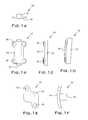
- FIGS. 1A, 1 B, and 1 Care top, front, and side elevation views of a cage plate in accordance with the invention, the plate being shown in a straight configuration;
- FIG. 1Dis a view similar to FIG. 1C in which the plate is curved;
- FIGS. 1E and 1Fare front and side elevations views of an alternate form of cage plate according to the invention.
- FIG. 2is an elevation view of the anterior of a portion of the cervical spine
- FIG. 3is a view similar to FIG. 2 in which a cage plate according to the invention has been installed;
- FIG. 4is a side elevation view of two representative vertebrae in which a cage plate according to the invention has been installed.
- FIG. 5is an illustration showing and describing the sequential steps by which the cage plate according to the invention is installed in a patient.
- a cage plate according to the inventionis indicated by the reference numeral 10 .
- the cage plate 10includes a spacer portion, or cage 12 , in the form of a porous biologically inert block in the form of a rectangular prism.
- the corners of the cage 12may be formed with a small radius if desired.
- the cage 12is sized to fit within an opening or graft bed formed between adjacent vertebrae by the surgical excision of a portion of the intervertebral disc and confronting portions of the adjacent vertebral bodies.
- the particular size of the cage 12will be determined by the particular vertebrae to be fused, and condition of the vertebrae.
- the cage 12is not made of a biological material, it can be easily stored and can be manufactured in a variety of shapes and sizes to accommodate anticipated situations.
- a typical cage 12 for fusing vertebrae of the lumbar spinemay be from 10 to 13 millimeters in width, 8 to 24 millimeters in height, and 25 to 30 millimeters in length.
- the table shown belowillustrates the various dimensions of typically sized cages 12 .
- intervertebral cage 12described herein is with reference to a cage for fusing vertebrae of the cervical spine
- the inventionapplies also to cages 12 for fusing vertebrae of the lumbar or thoracic spine as well.
- the particular shape of the cage 12also is a function of the application. While a generally rectangular cage 12 is well suited to fusing cervical or lumbar vertebrae, in other instances other shapes for the cage 12 , such as cylindrical or wedge-shaped, may be desirable.
- the cages 12 of the inventionmay also be used in other areas of the body to fuse bone together where necessary.
- the cage 12preferably is made of biologically inert beads or pellets having a diameter such as to yield, when fused, a cage 12 with the fused beads or pellets occupying a range of generally 45 to 75 percent of the volume of the cage 12 (voids thereby constituting 25-55% of the volume of the cage 12 ).
- beadsall small solid particles such as beads, pellets, grains, and the like that are suitable for use with the invention will be referred to hereafter as “beads.”
- This porosity described hereinprovides a cage 12 which is sufficiently porous throughout to allow for the flow of bodily fluids through the cage 12 and to promote tissue ingrowth and bony fusion with adjacent vertebrae.
- the beadsalso result in textured, porous surfaces over the cage 12 which when implanted develop a high-friction interface with the vertebral bodies to facilitate maintaining the cage 12 in place.
- the beadspreferably are composed of titanium, titanium alloy, or high strength polymers.
- a particularly desirable polymeris PEEK (polyaryl, ether, ether ketone) resin which is believed to be non-reactive within the body, or other high strength materials that are inert in the body.
- PEEK polymeris a high performance thermoplastic polymer made by Victrex pic of Westchester, Pa.
- PEEK polymeris semi-crystalline and is insoluble in all common solvents and has excellent resistance to a wide range of organic and inorganic liquids. The polymer retains excellent mechanical properties up to 572° F. It also can resist high dose levels of gamma radiation. It is an excellent choice for spinal implants and similar applications because it has a low value of coefficient of linear thermal expansion (2.6 ⁇ 10 ⁇ 5 ° F. by ASTM D696) up to the high glass transition temperature of 289° F. (T g by DSC).
- Suitable small beadswill have a mesh size of ⁇ 45 +60 (0.009 inch to 0.011 inch).
- Suitable medium beadswill have a mesh size of ⁇ 25 +30 (0.016 inch to 0.027 inch).
- Suitable large beadswill have a mesh size of ⁇ 18 +30 (0.032 inch to 0.046 inch).
- the size of the beadsdetermines the porosity of the finished cage 12 . The larger the beads, the greater the porosity. In certain applications, it may be desirable to mix beads of various sizes to obtain a finished cage 12 having a variable porosity.
- a solid metal or polymer cage 12also can be made porous by machining or otherwise forming holes or cavities throughout the cage 12 .
- Other materials suitable for use in making the cage 12include one or more of the following materials: cobalt-chromium alloys, tantalum, tantalum alloys, niobium, niobium alloys, and stainless steel.
- One method of fusing metal or polymer beads to form the cage 12includes placing the beads into a cavity within a mold.
- the moldpreferably is a three-piece mold forming a cavity of the finished dimensions of the cage 12 .
- the mold containing the beadsthen is heated to a temperature high enough to cause sintering to occur.
- Other methods for fusing beads or fibers which provide a sufficiently strong cage 12also may be acceptable.
- the fibersare used to form the cage 12 , the fibers are placed in the mold in a tangled, tortuous mass. Sintering produces strong inter-strand bonds with variably sized openings to form a cage 12 of suitable strength and porosity.
- the cage 12is attached to a plate 14 made of a biologically inert material such as stainless steel or titanium. It also is possible to form the plate from a high strength polymer such as PEEK or metals such as cobalt-chromium alloys, tantalum, tantalum alloys, niobium, niobium alloys, and stainless steel.
- the cage 12 and the plate 14will be made of the same material.
- the cage 12 and the plate 14will be fused to each other during the sintering process that produces the cage 12 . If the cage 12 and the plate 14 are made of metal, the cage 12 can be welded to the plate 14 .
- the particular type of attachment processis not important so long as (1) it utilizes materials that are inert in the body and (2) the cage 12 and the plate 14 cannot be separated from each other after installation in a patient.
- the plate 14has an opening 16 at each corner through which a screw or other fastener can be inserted. It is expected that the cage 12 will be installed vertically in a patient's spine (with the longitudinal axis of the cage 12 oriented vertically as shown in the drawings). When viewed from the end, the plate 14 is curved, with a radius of 40 mm. When viewed from the side, the plate 14 can be straight or curved. If curved, the plate 14 has a radius of approximately 100 mm. Due to the curvature of the plate 14 about its longitudinal axis, the screws inserted through the openings 16 will be inclined toward the longitudinal axis at an angle of about 15 degrees.
- FIGS. 1A-1Dillustrate such an arrangement, as well as the use of a non-rectangular plate 14 .
- the procedure for fusing two or more vertebrae together using the cage plate 10 of the inventionis substantially the same as the procedure for fusing vertebrae using a bone graft, but without many of the complications due to obtaining a suitable bone graft and the possibility of transmitting disease from the bone graft donor.
- One anterior procedure for implanting a bone graft to fuse vertebra of the lumbar spineis discussed in Collis et al., “ Anterior Total Disc Replacement: A Modified Anterior Lumbar Interbody Fusion ,” Lumbar Interbody Fusion, ed. Robert Watkins, Chapter 13, pp. 149-152, Aspen Publications (1989), the disclosure of which is incorporated herein by reference.
- FIGS. 2-4anterior views and a side elevation view of the cervical spine are shown.
- the cage 12 of the cage plate 10is installed in the same manner as is described in U.S. 5,961,554 at columns 4-5.
- the description set forth in FIG. 5describes a step-by-step methodology for installing the complete cage plate 10 in adjacent cervical vertebral bodies. It is to be understood that the length of the plate 14 and the cage 12 can be selected to fuse either two or three vertebrae of any portion of the spine.
Landscapes
- Health & Medical Sciences (AREA)
- Orthopedic Medicine & Surgery (AREA)
- Biomedical Technology (AREA)
- Engineering & Computer Science (AREA)
- Life Sciences & Earth Sciences (AREA)
- Veterinary Medicine (AREA)
- Animal Behavior & Ethology (AREA)
- Neurology (AREA)
- Oral & Maxillofacial Surgery (AREA)
- Heart & Thoracic Surgery (AREA)
- Public Health (AREA)
- General Health & Medical Sciences (AREA)
- Surgery (AREA)
- Molecular Biology (AREA)
- Medical Informatics (AREA)
- Dentistry (AREA)
- Nuclear Medicine, Radiotherapy & Molecular Imaging (AREA)
- Cardiology (AREA)
- Transplantation (AREA)
- Vascular Medicine (AREA)
- Prostheses (AREA)
Abstract
Description
Reference is made to U.S. Pat. No. 5,961,554, issued Oct. 5, 1999 to Frank S. Janson and Albert N. Santilli, the disclosure of which is incorporated herein by reference. Reference also is made to provisional application serial No. 60/117,487, filed Jan. 25, 2000 by Albert N. Santilli, the disclosure of which is incorporated herein by reference and from which priority is claimed.
1. Field of the Invention
The invention relates to spinal fusion and, more particularly, to the fusion of vertebral bodies through the use of a cage plate.
2. Description of the Prior Art
Techniques and devices for fusing two or more vertebrae of the spine together are well known. Such techniques are commonly performed to correct problems, such as chronic back pain, which result from degenerated intervertebral discs. One technique for fusing together two or more vertebrae of the lumbar spine includes excising a portion of the disc extending between adjacent vertebrae and grafting one or more portions of bone of a desired shape, known as an intervertebral spacer, between the adjacent vertebrae. The intervertebral spacer may be inserted by either an anterior or posterior approach to the spinal column depending on a number of factors, including the number of vertebrae to be fused and past operative procedures. Upon healing, the vertebrae are desirably fused together through the intervertebral spacer.
Conventionally, intervertebral spacers have been autogenic bone harvested from other areas of the body, such as the pelvis, allogenic bone taken from cadavers or xenogenic bone, such as bovine bone sections. However, the use of bone grafts can add complications to the fusion procedure. For example, when using an autogenic bone graft, a second incision must be made in the patient to harvest the additional bone to be used in the graft, thus increasing the pain and blood loss to the patient. When allogenic or xenogenic bone grafts are used there is a potential for the transmission of disease or infection from the cadaver or other graft source to the patient, as well as rejection of the graft.
The use of non-biological implants, such as carbon fiber spacers, also has been attempted in the past, but these spacers tend to lack sufficient porosity and tissue ingrowth characteristics to function adequately. However, the spacer disclosed in U.S. Pat. No. 5,961,554 is made of sintered titanium beads which provide excellent porosity and strength.
Apart from spacers per se, spinal fusion has been accomplished by attaching various external devices such as rods that are screwed to adjacent vertebral bodies. Examples of such devices are disclosed in U.S. Pat. Nos. 5,382,248 and 5,611,800. These types of devices are versatile in the sense that both adjacent vertebrae and spaced vertebrae can be fused, depending on the patient's needs. Unfortunately, although such devices have been used successfully, they are complex to manufacture and are difficult to install, thereby prolonging the surgical installation procedure. Furthermore, they do not have the capability to provide bony ingrowth that will occur when porous spacers are used.
It would be desirable to have a non-biological spacer which is non-reactive in the body and which has the strength and tissue ingrowth characteristics of a bone graft spacer. It also would be desirable to have a spinal fusion technique that has the strength and versatility of known rod and screw techniques without the installation difficulties associated therewith.
In response to the foregoing concerns, the present invention provides a porous intervertebral spacer, or cage, that can be used in the same manner as a bone graft spacer to fuse vertebrae together. The present invention also includes a plate to which the cage is attached. The plate is connected to the vertebral bodies that are being fused together, preferably by the use of bone screws. In combination, the cage and the plate provide superior fusion capability and strength, ease of installation, and bony ingrowth characteristics.
The cage according to the invention can be made of a variety of substances that are inert to the body and which will not be rejected by the body. Sintered titanium or titanium alloy beads or wire mesh of titanium or titanium alloys as disclosed in U.S. Pat. No. 5,961,554 are the preferred materials for the cage. Another possibility is pellets of PEEK (polyaryl, ether, ether ketone) polymer or other strong polymers sintered in a mold of a desired shape and size. Other suitable materials include cobalt-chromium alloys, tantalum, tantalum alloys, niobium, niobium alloys, and stainless steel. Provided an appropriate material is chosen, the cage will be non-biologically reactive and will provide for tissue ingrowth to facilitate fusion with adjacent vertebrae. A solid metal or polymer cage also can be made porous by machining or otherwise forming holes or cavities throughout the cage. The cage can be formed in a variety of shapes such as a prism (for example, a rectangular prism), a cylinder, or a plate. Generally, it is expected that the cage will be a vertically oriented strut having a square or rectangular cross-section.
The plate to which the cage is attached preferably is a thin, generally rectangular member that is made of the same material as the cage. The plate includes openings at or near its corners through which bone screws can extend. In top view the plate is curved, with a radius of approximately 40 mm. In side elevation, the plate either can be straight or curved, with a radius of approximately 100 mm when curved. The amount of curvature, if any, is a function of the particular vertebrae to which the plate is to be connected. The plate can be formed in other shapes, if desired.
The foregoing and other features and advantages of the invention are described in more detail in the accompanying specification, claims, and drawings.
FIGS. 1A,1B, and1C are top, front, and side elevation views of a cage plate in accordance with the invention, the plate being shown in a straight configuration;
FIG. 1D is a view similar to FIG. 1C in which the plate is curved;
FIGS. 1E and 1F are front and side elevations views of an alternate form of cage plate according to the invention;
FIG. 2 is an elevation view of the anterior of a portion of the cervical spine;
FIG. 3 is a view similar to FIG. 2 in which a cage plate according to the invention has been installed;
FIG. 4 is a side elevation view of two representative vertebrae in which a cage plate according to the invention has been installed; and
FIG. 5 is an illustration showing and describing the sequential steps by which the cage plate according to the invention is installed in a patient.
With reference to the drawings and initially to FIGS. 1A-1F, a cage plate according to the invention is indicated by thereference numeral 10. Thecage plate 10 includes a spacer portion, orcage 12, in the form of a porous biologically inert block in the form of a rectangular prism. The corners of thecage 12 may be formed with a small radius if desired. Thecage 12 is sized to fit within an opening or graft bed formed between adjacent vertebrae by the surgical excision of a portion of the intervertebral disc and confronting portions of the adjacent vertebral bodies. The particular size of thecage 12 will be determined by the particular vertebrae to be fused, and condition of the vertebrae. Advantageously, because thecage 12 is not made of a biological material, it can be easily stored and can be manufactured in a variety of shapes and sizes to accommodate anticipated situations. Atypical cage 12 for fusing vertebrae of the lumbar spine may be from 10 to 13 millimeters in width, 8 to 24 millimeters in height, and 25 to 30 millimeters in length. The table shown below illustrates the various dimensions of typicallysized cages 12.
| MODEL | HEIGHT (H) | WIDTH (W) | LENGTH (L) | ||
| STRAIGHT | |||||
| 1 | 25 | 5 mm | 6 | ||
| 2 | 32 | 5 mm | 6 | ||
| 3 | 40 | 5 mm, 7 mm | 6 mm, 8 | ||
| 4 | 47 | 5 mm, 7 mm | 6 mm, 8 | ||
| 5 | 58 mm | 6 mm, 8 | 10 mm | ||
| CURVED | |||||
| 1C | 25 | 5 mm | 6 mm | ||
| 2C | 32 | 5 mm | 6 | ||
| 3C | |||||
| 40 | 5 mm, 7 mm | 6 mm, 8 mm | |||
| 4C | 47 | 5 mm, 7 mm | 6 mm, 8 mm | ||
| 5C | 58 mm | 6 mm, 8 | 10 mm | ||
It will be appreciated that while a specific example of theintervertebral cage 12 described herein is with reference to a cage for fusing vertebrae of the cervical spine, the invention applies also tocages 12 for fusing vertebrae of the lumbar or thoracic spine as well. The particular shape of thecage 12 also is a function of the application. While a generallyrectangular cage 12 is well suited to fusing cervical or lumbar vertebrae, in other instances other shapes for thecage 12, such as cylindrical or wedge-shaped, may be desirable. Moreover, it will be recognized that thecages 12 of the invention may also be used in other areas of the body to fuse bone together where necessary.
Thecage 12 preferably is made of biologically inert beads or pellets having a diameter such as to yield, when fused, acage 12 with the fused beads or pellets occupying a range of generally 45 to 75 percent of the volume of the cage12 (voids thereby constituting 25-55% of the volume of the cage12). For convenience of description, all small solid particles such as beads, pellets, grains, and the like that are suitable for use with the invention will be referred to hereafter as “beads.” This porosity described herein provides acage 12 which is sufficiently porous throughout to allow for the flow of bodily fluids through thecage 12 and to promote tissue ingrowth and bony fusion with adjacent vertebrae. The beads also result in textured, porous surfaces over thecage 12 which when implanted develop a high-friction interface with the vertebral bodies to facilitate maintaining thecage 12 in place.
The beads preferably are composed of titanium, titanium alloy, or high strength polymers. A particularly desirable polymer is PEEK (polyaryl, ether, ether ketone) resin which is believed to be non-reactive within the body, or other high strength materials that are inert in the body. PEEK polymer is a high performance thermoplastic polymer made by Victrex pic of Westchester, Pa. PEEK polymer is semi-crystalline and is insoluble in all common solvents and has excellent resistance to a wide range of organic and inorganic liquids. The polymer retains excellent mechanical properties up to 572° F. It also can resist high dose levels of gamma radiation. It is an excellent choice for spinal implants and similar applications because it has a low value of coefficient of linear thermal expansion (2.6×10⁻⁵° F. by ASTM D696) up to the high glass transition temperature of 289° F. (Tgby DSC).
It has been found that beads of a certain size range are preferred. Suitable small beads will have a mesh size of −45 +60 (0.009 inch to 0.011 inch). Suitable medium beads will have a mesh size of −25 +30 (0.016 inch to 0.027 inch). Suitable large beads will have a mesh size of −18 +30 (0.032 inch to 0.046 inch). The size of the beads determines the porosity of thefinished cage 12. The larger the beads, the greater the porosity. In certain applications, it may be desirable to mix beads of various sizes to obtain afinished cage 12 having a variable porosity.
It is possible to intermix fibers of PEEK polymer with the PEEK beads to form acage 12 having variable qualities of strength and porosity. Similarly, titanium fibers can be intermixed with titanium beads. In general, the use of fibers results in a stronger, lessporous cage 12. It also is possible to form thecage 12 entirely of fibers. A solid metal orpolymer cage 12 also can be made porous by machining or otherwise forming holes or cavities throughout thecage 12. Other materials suitable for use in making thecage 12 include one or more of the following materials: cobalt-chromium alloys, tantalum, tantalum alloys, niobium, niobium alloys, and stainless steel.
One method of fusing metal or polymer beads to form thecage 12 includes placing the beads into a cavity within a mold. The mold preferably is a three-piece mold forming a cavity of the finished dimensions of thecage 12. The mold containing the beads then is heated to a temperature high enough to cause sintering to occur. Other methods for fusing beads or fibers which provide a sufficientlystrong cage 12 also may be acceptable. When fibers are used to form thecage 12, the fibers are placed in the mold in a tangled, tortuous mass. Sintering produces strong inter-strand bonds with variably sized openings to form acage 12 of suitable strength and porosity.
In FIG. 1, thecage 12 is attached to aplate 14 made of a biologically inert material such as stainless steel or titanium. It also is possible to form the plate from a high strength polymer such as PEEK or metals such as cobalt-chromium alloys, tantalum, tantalum alloys, niobium, niobium alloys, and stainless steel. Preferably, thecage 12 and theplate 14 will be made of the same material. Typically, thecage 12 and theplate 14 will be fused to each other during the sintering process that produces thecage 12. If thecage 12 and theplate 14 are made of metal, thecage 12 can be welded to theplate 14. The particular type of attachment process is not important so long as (1) it utilizes materials that are inert in the body and (2) thecage 12 and theplate 14 cannot be separated from each other after installation in a patient.
Theplate 14 has anopening 16 at each corner through which a screw or other fastener can be inserted. It is expected that thecage 12 will be installed vertically in a patient's spine (with the longitudinal axis of thecage 12 oriented vertically as shown in the drawings). When viewed from the end, theplate 14 is curved, with a radius of 40 mm. When viewed from the side, theplate 14 can be straight or curved. If curved, theplate 14 has a radius of approximately 100 mm. Due to the curvature of theplate 14 about its longitudinal axis, the screws inserted through theopenings 16 will be inclined toward the longitudinal axis at an angle of about 15 degrees.
As indicated previously, various sizes of thecage 12 are shown in the table set forth above. It is to be understood that the dimensions of thecage 12 can be chosen to suit the needs of the patient. In particular, although thecage 12 is illustrated in FIGS. 1A-1D as having a larger vertical dimension than theplate 14, it is expected that thecage 12 frequently will have a smaller vertical dimension than theplate 14. Indeed, it is entirely possible and desirable that thecage 12 will have a smaller vertical dimension than the distance between theopenings 16 on opposite ends of theplate 14. FIGS. 1E and 1F illustrate such an arrangement, as well as the use of anon-rectangular plate 14.
The procedure for fusing two or more vertebrae together using thecage plate 10 of the invention is substantially the same as the procedure for fusing vertebrae using a bone graft, but without many of the complications due to obtaining a suitable bone graft and the possibility of transmitting disease from the bone graft donor. One anterior procedure for implanting a bone graft to fuse vertebra of the lumbar spine is discussed in Collis et al., “Anterior Total Disc Replacement: A Modified Anterior Lumbar Interbody Fusion,” Lumbar Interbody Fusion, ed. Robert Watkins, Chapter 13, pp. 149-152, Aspen Publications (1989), the disclosure of which is incorporated herein by reference.
Referring to FIGS. 2-4, anterior views and a side elevation view of the cervical spine are shown. Thecage 12 of thecage plate 10 is installed in the same manner as is described in U.S. 5,961,554 at columns 4-5. The description set forth in FIG. 5 describes a step-by-step methodology for installing thecomplete cage plate 10 in adjacent cervical vertebral bodies. It is to be understood that the length of theplate 14 and thecage 12 can be selected to fuse either two or three vertebrae of any portion of the spine.
It is to be understood that the present disclosure of the preferred embodiment has been made only by way of example, and that various changes may be resorted to without departing from the true spirit and scope of the invention as hereinafter claimed. It is intended that the patent shall cover, by suitable expression in the appended claims, whatever degree of patentable novelty exists in the invention disclosed.
Claims (8)
1. A cage plate for fusing selected vertebral bodies of a patient's spinal column in which an opening has been formed, comprising:
a cage made of a biologically inert material, the cage having voids that constitute approximately 25 to 55 percent of the volume of the cage and being sufficiently porous to facilitate bony ingrowth and spinal fusion, the cage adapted to be inserted into the opening in the spinal column; and
a plate to which the cage is attached, the plate being made of a biologically inert material, the plate adapted to be connected to the spinal column.
2. The cage plate ofclaim 1 , wherein the cage is made of one or more materials selected from the group consisting of titanium, titanium alloys, PEEK (polyaryl, ether, ether ketone) polymer, cobalt-chromium alloys, tantalum, tantalum alloys, niobium, niobium alloys, and stainless steel.
3. The cage plate ofclaim 1 , wherein the plate is generally rectangular and has a longitudinal axis that in use is disposed parallel with the longitudinal axis of the spinal column, the plate being curved when viewed from the top, the curvature approximating that of the vertebral bodies to be fused, and the plate being curved when viewed from the side, the curvature approximating that of the vertebral bodies to be fused.
4. The cage plate ofclaim 1 , further comprising means for attaching the plate to the vertebral bodies.
5. The cage plate ofclaim 4 , wherein the means for attaching the plate to the vertebral bodies includes a plurality of openings in the plate and bone screws that can be screwed into the vertebral bodies through the openings in the plate.
6. A cage plate for fusing selected vertebral bodies of a patient's spinal column in which an opening has been formed; comprising:
a cage made of one or more biologically inert materials selected from the group consisting of titanium, titanium alloys, PEEK (polyaryl, ether, ether ketone) polymer, cobalt-chromium alloys, tantalum, tantalum alloys, niobium, niobium alloys, and stainless steel, the cage having voids that form a porosity within the range of about 25 to 55 percent of the volume of the cage and being able to facilitate bony ingrowth and spinal fusion, the cage adapted to be inserted into the opening in the spinal column; and
a plate to which the cage is attached, the plate being made of a biologically inert material selected from the group consisting of titanium, titanium alloys, PEEK (polyaryl, ether, ether ketone) polymer, cobalt-chromium alloys, tantalum, tantalum alloys, niobium, niobium alloys, and stainless steel, the plate adapted to be connected to the spinal column, the plate being generally rectangular and having a longitudinal axis that in use is disposed parallel with the longitudinal axis of the spinal column, the plate being curved when viewed from the top, the curvature approximating that of the vertebral bodies to be fused, and the plate being curved when viewed from the side, the curvature approximating that of the vertebral bodies to be fused, the plate having a plurality of openings adjacent the corners thereof through which bone screws can be inserted and screwed into the vertebral bodies.
7. A method for fusing vertebral bodies of a patient's spinal column, comprising the steps of:
providing a cage made of a biologically inert material, the cage having voids that constitute approximately 25 to 55 percent of the volume of the cage and being sufficiently porous to facilitate bony ingrowth and spinal fusion;
providing a plate, the plate being made of a biologically inert material;
attaching the cage to the plate;
forming an opening in the spinal column;
inserting the cage in the opening; and
connecting the plate to the vertebral bodies to be fused.
8. The method ofclaim 7 , wherein the step of connecting is accomplished by:
forming openings in the plate;
forming openings in the vertebral bodies to be fused;
providing bone screws; and
inserting the bone screws into the vertebral bodies through the openings in the plate.
Priority Applications (2)
| Application Number | Priority Date | Filing Date | Title |
|---|---|---|---|
| US09/792,694US6572619B2 (en) | 2001-02-23 | 2001-02-23 | Cage plate for spinal fusion and method of operation |
| US10/004,916US6673075B2 (en) | 2001-02-23 | 2001-12-03 | Porous intervertebral spacer |
Applications Claiming Priority (1)
| Application Number | Priority Date | Filing Date | Title |
|---|---|---|---|
| US09/792,694US6572619B2 (en) | 2001-02-23 | 2001-02-23 | Cage plate for spinal fusion and method of operation |
Related Child Applications (1)
| Application Number | Title | Priority Date | Filing Date |
|---|---|---|---|
| US10/004,916Continuation-In-PartUS6673075B2 (en) | 2001-02-23 | 2001-12-03 | Porous intervertebral spacer |
Publications (2)
| Publication Number | Publication Date |
|---|---|
| US20020151893A1 US20020151893A1 (en) | 2002-10-17 |
| US6572619B2true US6572619B2 (en) | 2003-06-03 |
Family
ID=25157760
Family Applications (1)
| Application Number | Title | Priority Date | Filing Date |
|---|---|---|---|
| US09/792,694Expired - LifetimeUS6572619B2 (en) | 2001-02-23 | 2001-02-23 | Cage plate for spinal fusion and method of operation |
Country Status (1)
| Country | Link |
|---|---|
| US (1) | US6572619B2 (en) |
Cited By (85)
| Publication number | Priority date | Publication date | Assignee | Title |
|---|---|---|---|---|
| US20050123581A1 (en)* | 2003-12-04 | 2005-06-09 | Ringeisen Timothy A. | Compressed high density fibrous polymers suitable for implant |
| US20060095136A1 (en)* | 2004-11-03 | 2006-05-04 | Mcluen Design, Inc. | Bone fusion device |
| US20060285991A1 (en)* | 2005-04-27 | 2006-12-21 | Mckinley Laurence M | Metal injection moulding for the production of medical implants |
| US7204837B2 (en) | 2001-12-14 | 2007-04-17 | Paul Kamaljit S | Spinal plate assembly |
| US7255699B2 (en) | 2001-12-14 | 2007-08-14 | Paul Kamaljit S | Spinal plate assembly |
| US20070213826A1 (en)* | 2006-03-08 | 2007-09-13 | Seaspine, Inc. | Intervertebral spacer and insertion tool providing multiple angles of insertion |
| US7306605B2 (en) | 2003-10-02 | 2007-12-11 | Zimmer Spine, Inc. | Anterior cervical plate |
| US20070299442A1 (en)* | 2006-06-26 | 2007-12-27 | Sdgi Holdings, Inc. | Vertebral stabilizer |
| US20080021476A1 (en)* | 2003-09-30 | 2008-01-24 | X-Spine Systems, Inc. | Spinal fusion system utilizing an implant plate having at least one integral lock and ratchet lock |
| US20080161927A1 (en)* | 2006-10-18 | 2008-07-03 | Warsaw Orthopedic, Inc. | Intervertebral Implant with Porous Portions |
| US20080249626A1 (en)* | 2007-04-05 | 2008-10-09 | Santilli Albert N | Arthrodesis of Vertebral Bodies |
| US20090054986A1 (en)* | 2005-05-02 | 2009-02-26 | Cordaro Nicholas M | Motion restoring intervertebral device |
| US20090062916A1 (en)* | 2007-08-27 | 2009-03-05 | Biomedical Enterprises, Inc. | Method and apparatus for an osteotomy fixation or arthrodesis cage |
| US20090076555A1 (en)* | 2007-09-13 | 2009-03-19 | David Lowry | Transcorporeal spinal decompression and repair system and related method |
| US20090082868A1 (en)* | 2005-05-02 | 2009-03-26 | Cordaro Nicholas M | Prosthesis for restoring motion in an appendage or spinal joint and an intervertebral spacer |
| US20090306779A1 (en)* | 2008-06-05 | 2009-12-10 | Alphatec Spine, Inc. | Modular anterior locking interbody cage |
| US20100057134A1 (en)* | 2007-08-07 | 2010-03-04 | David Lowry | Implantable bone plate system and related method for spinal repair |
| US7723395B2 (en) | 2004-04-29 | 2010-05-25 | Kensey Nash Corporation | Compressed porous materials suitable for implant |
| US20100145453A1 (en)* | 2003-09-30 | 2010-06-10 | X-Spine Systems, Inc. | Fusion system and method for fusing spinal bones |
| US20100152793A1 (en)* | 2007-09-13 | 2010-06-17 | David Lowry | Transcorporeal spinal decompression and repair systems and related methods |
| US20100152784A1 (en)* | 2007-08-07 | 2010-06-17 | David Lowry | Implantable vertebral frame systems and related methods for spinal repair |
| US7740649B2 (en) | 2004-02-26 | 2010-06-22 | Pioneer Surgical Technology, Inc. | Bone plate system and methods |
| US20100161057A1 (en)* | 2008-12-19 | 2010-06-24 | Amicus, Llc | Interbody Vertebral Prosthetic Device With Self-Deploying Screws |
| US7766947B2 (en) | 2001-10-31 | 2010-08-03 | Ortho Development Corporation | Cervical plate for stabilizing the human spine |
| US7799081B2 (en) | 2004-09-14 | 2010-09-21 | Aeolin, Llc | System and method for spinal fusion |
| WO2010115132A2 (en) | 2009-04-03 | 2010-10-07 | Warsaw Orthopedic, Inc. | Medical implant with bioactive material and method of making the medical implant |
| US20100278891A1 (en)* | 2003-12-04 | 2010-11-04 | Ringeisen Timothy A | Bi-phasic compressed porous reinforcement materials suitable for implant |
| US7887595B1 (en) | 2005-12-05 | 2011-02-15 | Nuvasive, Inc. | Methods and apparatus for spinal fusion |
| US20110054535A1 (en)* | 2009-08-28 | 2011-03-03 | Gephart Matthew P | Size Transition Spinal Rod |
| US20110071570A1 (en)* | 2009-09-24 | 2011-03-24 | Warsaw Orthopedic, Inc. | Composite vertebral rod system and methods of use |
| US20110218574A1 (en)* | 2010-03-03 | 2011-09-08 | Warsaw Orthopedic, Inc. | Dynamic vertebral construct |
| US8114162B1 (en) | 2006-08-09 | 2012-02-14 | Nuvasive, Inc. | Spinal fusion implant and related methods |
| US8172885B2 (en) | 2003-02-05 | 2012-05-08 | Pioneer Surgical Technology, Inc. | Bone plate system |
| US20120303124A1 (en)* | 2004-11-03 | 2012-11-29 | Mcluen Gary R | Bone fusion device |
| WO2013008111A1 (en) | 2011-07-14 | 2013-01-17 | Kamil Bal | Fixation system for spinal cages |
| US8361126B2 (en) | 2007-07-03 | 2013-01-29 | Pioneer Surgical Technology, Inc. | Bone plate system |
| US8409290B2 (en) | 2006-03-08 | 2013-04-02 | Seaspine, Inc. | Interbody device for spinal applications |
| US8425569B2 (en) | 2010-05-19 | 2013-04-23 | Transcorp, Inc. | Implantable vertebral frame systems and related methods for spinal repair |
| US8475533B1 (en) | 2012-09-27 | 2013-07-02 | Igip, Llc | System and stabilizer for spinal implant and methods of assisting stabilization of spinal implant |
| US8623019B2 (en) | 2007-07-03 | 2014-01-07 | Pioneer Surgical Technology, Inc. | Bone plate system |
| US8685104B2 (en) | 2012-03-19 | 2014-04-01 | Amicus Design Group, Llc | Interbody vertebral prosthetic and orthopedic fusion device with self-deploying anchors |
| US8734493B2 (en) | 2003-09-30 | 2014-05-27 | X-Spine Systems, Inc. | Screw locking mechanism and method |
| US8753396B1 (en) | 2010-09-13 | 2014-06-17 | Theken Spine, Llc | Intervertebral implant having back-out prevention feature |
| USD708747S1 (en) | 2006-09-25 | 2014-07-08 | Nuvasive, Inc. | Spinal fusion implant |
| US8808294B2 (en) | 2008-09-09 | 2014-08-19 | William Casey Fox | Method and apparatus for a multiple transition temperature implant |
| US8821553B2 (en) | 2003-09-30 | 2014-09-02 | X-Spine Systems, Inc. | Spinal fusion system utilizing an implant plate having at least one integral lock |
| US8900277B2 (en) | 2004-02-26 | 2014-12-02 | Pioneer Surgical Technology, Inc. | Bone plate system |
| US8926664B1 (en) | 2006-11-07 | 2015-01-06 | Globus Medical, Inc. | Laminoplasty fixaction devices |
| US8956415B2 (en) | 2010-08-15 | 2015-02-17 | Warsaw Orthopedic, Inc. | Vertebral implant |
| US9078706B2 (en) | 2003-09-30 | 2015-07-14 | X-Spine Systems, Inc. | Intervertebral fusion device utilizing multiple mobile uniaxial and bidirectional screw interface plates |
| US9144506B2 (en) | 2011-08-11 | 2015-09-29 | Jeff Phelps | Interbody axis cage |
| US9248028B2 (en) | 2011-09-16 | 2016-02-02 | DePuy Synthes Products, Inc. | Removable, bone-securing cover plate for intervertebral fusion cage |
| US9358123B2 (en) | 2011-08-09 | 2016-06-07 | Neuropro Spinal Jaxx, Inc. | Bone fusion device, apparatus and method |
| US9526525B2 (en) | 2006-08-22 | 2016-12-27 | Neuropro Technologies, Inc. | Percutaneous system for dynamic spinal stabilization |
| US9526620B2 (en) | 2009-03-30 | 2016-12-27 | DePuy Synthes Products, Inc. | Zero profile spinal fusion cage |
| US9532883B2 (en) | 2012-04-13 | 2017-01-03 | Neuropro Technologies, Inc. | Bone fusion device |
| US9566165B2 (en) | 2012-03-19 | 2017-02-14 | Amicus Design Group, Llc | Interbody vertebral prosthetic and orthopedic fusion device with self-deploying anchors |
| WO2017031234A1 (en)* | 2015-08-17 | 2017-02-23 | Spinal Usa, Inc. | Spinal screws and methods of using the same |
| US9662225B2 (en) | 2012-03-06 | 2017-05-30 | DePuy Synthes Products, Inc. | Nubbed plate |
| US9687354B2 (en) | 2008-03-26 | 2017-06-27 | DePuy Synthes Products, Inc. | Posterior intervertebral disc inserter and expansion techniques |
| US9987052B2 (en) | 2015-02-24 | 2018-06-05 | X-Spine Systems, Inc. | Modular interspinous fixation system with threaded component |
| US10058432B2 (en) | 2016-03-03 | 2018-08-28 | Globus Medical, Inc. | Lamina plate assembly |
| US10098757B2 (en) | 2013-03-15 | 2018-10-16 | Neuropro Technologies Inc. | Bodiless bone fusion device, apparatus and method |
| US10111760B2 (en) | 2017-01-18 | 2018-10-30 | Neuropro Technologies, Inc. | Bone fusion system, device and method including a measuring mechanism |
| US10159583B2 (en) | 2012-04-13 | 2018-12-25 | Neuropro Technologies, Inc. | Bone fusion device |
| US10182921B2 (en) | 2012-11-09 | 2019-01-22 | DePuy Synthes Products, Inc. | Interbody device with opening to allow packing graft and other biologics |
| US10206787B2 (en) | 2006-12-22 | 2019-02-19 | Medos International Sarl | Composite vertebral spacers and instrument |
| US10213321B2 (en) | 2017-01-18 | 2019-02-26 | Neuropro Technologies, Inc. | Bone fusion system, device and method including delivery apparatus |
| US10226284B2 (en) | 2011-09-01 | 2019-03-12 | Globus Medical, Inc. | Laminoplasty plates, systems, and devices, and methods relating to the same |
| US10292830B2 (en) | 2011-08-09 | 2019-05-21 | Neuropro Technologies, Inc. | Bone fusion device, system and method |
| US10335289B2 (en) | 2010-09-23 | 2019-07-02 | DePuy Synthes Products, Inc. | Stand alone intervertebral fusion device |
| US10369015B2 (en) | 2010-09-23 | 2019-08-06 | DePuy Synthes Products, Inc. | Implant inserter having a laterally-extending dovetail engagement feature |
| US10376292B2 (en) | 2016-03-03 | 2019-08-13 | Globus Medical, Inc | Lamina plate assembly |
| US10420654B2 (en) | 2011-08-09 | 2019-09-24 | Neuropro Technologies, Inc. | Bone fusion device, system and method |
| US20190290445A1 (en)* | 2007-09-13 | 2019-09-26 | Globus Medical, Inc. | Transcorporeal spinal decompression and repair systems and related methods |
| US10500062B2 (en) | 2009-12-10 | 2019-12-10 | DePuy Synthes Products, Inc. | Bellows-like expandable interbody fusion cage |
| US10667916B2 (en) | 2016-03-03 | 2020-06-02 | Globus Medical, Inc. | Lamina plate assembly |
| US10709482B2 (en) | 2012-05-30 | 2020-07-14 | Globus Medical, Inc. | Laminoplasty system |
| US10729560B2 (en) | 2017-01-18 | 2020-08-04 | Neuropro Technologies, Inc. | Bone fusion system, device and method including an insertion instrument |
| US10932922B2 (en) | 2018-04-20 | 2021-03-02 | JWD Products, LLC | Spinal implant insertion tool |
| US10940016B2 (en) | 2017-07-05 | 2021-03-09 | Medos International Sarl | Expandable intervertebral fusion cage |
| US10973657B2 (en) | 2017-01-18 | 2021-04-13 | Neuropro Technologies, Inc. | Bone fusion surgical system and method |
| US11324609B2 (en) | 2018-04-20 | 2022-05-10 | JWD Products, LLC | Spinal implant insertion tool |
| US11529241B2 (en) | 2010-09-23 | 2022-12-20 | DePuy Synthes Products, Inc. | Fusion cage with in-line single piece fixation |
| US11877779B2 (en) | 2020-03-26 | 2024-01-23 | Xtant Medical Holdings, Inc. | Bone plate system |
Families Citing this family (15)
| Publication number | Priority date | Publication date | Assignee | Title |
|---|---|---|---|---|
| FR2897259B1 (en) | 2006-02-15 | 2008-05-09 | Ldr Medical Soc Par Actions Si | INTERSOMATIC TRANSFORAMINAL CAGE WITH INTERBREBAL FUSION GRAFT AND CAGE IMPLANTATION INSTRUMENT |
| FR2808995B1 (en) | 2000-05-18 | 2003-02-21 | Aesculap Sa | INTERSOMATIC CAGE WITH UNIFIED GRAFT |
| FR2827156B1 (en) | 2001-07-13 | 2003-11-14 | Ldr Medical | VERTEBRAL CAGE DEVICE WITH MODULAR FASTENING |
| DE10253170A1 (en)* | 2002-11-14 | 2004-06-03 | Sepitec Foundation | Implant used in procedures for stiffening the vertebral column consists of a compression-resistant hollow body made from two open receptacles which are pressed apart with insertion of filler material |
| US7326200B2 (en)* | 2003-07-25 | 2008-02-05 | Warsaw Orthopedic, Inc. | Annulus repair systems, instruments and techniques |
| US7621938B2 (en)* | 2004-01-15 | 2009-11-24 | Warsaw Orthopedic, Inc. | Spinal implant construct and method for implantation |
| EP2113227B1 (en) | 2004-02-04 | 2015-07-29 | LDR Medical | Intervertebral disc prosthesis |
| FR2891135B1 (en) | 2005-09-23 | 2008-09-12 | Ldr Medical Sarl | INTERVERTEBRAL DISC PROSTHESIS |
| US7520888B2 (en) | 2006-02-14 | 2009-04-21 | Warsaw Orthopedic, Inc. | Treatment of the vertebral column |
| FR2916956B1 (en) | 2007-06-08 | 2012-12-14 | Ldr Medical | INTERSOMATIC CAGE, INTERVERTEBRAL PROSTHESIS, ANCHORING DEVICE AND IMPLANTATION INSTRUMENTATION |
| US8377136B2 (en)* | 2009-04-20 | 2013-02-19 | Warsaw Orthopedic, Inc. | Method for stabilizing an intervertebral disc device |
| CN105326585B (en) | 2009-09-17 | 2018-12-11 | Ldr控股公司 | Intervertebral implant with extensible bone anchoring element |
| WO2011080535A1 (en) | 2009-12-31 | 2011-07-07 | Lrd Medical | Anchoring device, intervertebral implant and implantation instrument |
| FR2987256B1 (en) | 2012-02-24 | 2014-08-08 | Ldr Medical | ANCHORING DEVICE FOR INTERVERTEBRAL IMPLANT, INTERVERTEBRAL IMPLANT AND IMPLANTATION INSTRUMENTATION |
| CN111281611B (en)* | 2019-12-30 | 2022-05-24 | 雅博尼西医疗科技(苏州)有限公司 | Method for connecting porous structure and substrate |
Citations (9)
| Publication number | Priority date | Publication date | Assignee | Title |
|---|---|---|---|---|
| US4892545A (en)* | 1988-07-14 | 1990-01-09 | Ohio Medical Instrument Company, Inc. | Vertebral lock |
| US5382248A (en) | 1992-09-10 | 1995-01-17 | H. D. Medical, Inc. | System and method for stabilizing bone segments |
| US5611800A (en) | 1994-02-15 | 1997-03-18 | Alphatec Manufacturing, Inc. | Spinal fixation system |
| US5749875A (en)* | 1995-03-24 | 1998-05-12 | Arthrex, Inc. | Bone plate system for proximal tibial osteotomy |
| US5961554A (en)* | 1996-12-31 | 1999-10-05 | Janson; Frank S | Intervertebral spacer |
| US6066175A (en)* | 1993-02-16 | 2000-05-23 | Henderson; Fraser C. | Fusion stabilization chamber |
| US6231610B1 (en)* | 1999-08-25 | 2001-05-15 | Allegiance Corporation | Anterior cervical column support device |
| US6235059B1 (en)* | 1996-04-03 | 2001-05-22 | Scient'x (Societe A Responsabilite Limitee) | Intersomatic setting and fusion system |
| US6395030B1 (en)* | 1998-06-18 | 2002-05-28 | Michigan Technological University | Spinal fixation system |
- 2001
- 2001-02-23USUS09/792,694patent/US6572619B2/ennot_activeExpired - Lifetime
Patent Citations (9)
| Publication number | Priority date | Publication date | Assignee | Title |
|---|---|---|---|---|
| US4892545A (en)* | 1988-07-14 | 1990-01-09 | Ohio Medical Instrument Company, Inc. | Vertebral lock |
| US5382248A (en) | 1992-09-10 | 1995-01-17 | H. D. Medical, Inc. | System and method for stabilizing bone segments |
| US6066175A (en)* | 1993-02-16 | 2000-05-23 | Henderson; Fraser C. | Fusion stabilization chamber |
| US5611800A (en) | 1994-02-15 | 1997-03-18 | Alphatec Manufacturing, Inc. | Spinal fixation system |
| US5749875A (en)* | 1995-03-24 | 1998-05-12 | Arthrex, Inc. | Bone plate system for proximal tibial osteotomy |
| US6235059B1 (en)* | 1996-04-03 | 2001-05-22 | Scient'x (Societe A Responsabilite Limitee) | Intersomatic setting and fusion system |
| US5961554A (en)* | 1996-12-31 | 1999-10-05 | Janson; Frank S | Intervertebral spacer |
| US6395030B1 (en)* | 1998-06-18 | 2002-05-28 | Michigan Technological University | Spinal fixation system |
| US6231610B1 (en)* | 1999-08-25 | 2001-05-15 | Allegiance Corporation | Anterior cervical column support device |
Cited By (177)
| Publication number | Priority date | Publication date | Assignee | Title |
|---|---|---|---|---|
| US7766947B2 (en) | 2001-10-31 | 2010-08-03 | Ortho Development Corporation | Cervical plate for stabilizing the human spine |
| US7255699B2 (en) | 2001-12-14 | 2007-08-14 | Paul Kamaljit S | Spinal plate assembly |
| US8221476B2 (en) | 2001-12-14 | 2012-07-17 | Paul Kamaljit S | Spinal plate assembly |
| US8236033B2 (en) | 2001-12-14 | 2012-08-07 | Paul Kamaljit S | Spinal plate assembly |
| US7204837B2 (en) | 2001-12-14 | 2007-04-17 | Paul Kamaljit S | Spinal plate assembly |
| US8172885B2 (en) | 2003-02-05 | 2012-05-08 | Pioneer Surgical Technology, Inc. | Bone plate system |
| US8282682B2 (en)* | 2003-09-30 | 2012-10-09 | X-Spine Systems, Inc. | Fusion system and method for fusing spinal bones |
| US9078706B2 (en) | 2003-09-30 | 2015-07-14 | X-Spine Systems, Inc. | Intervertebral fusion device utilizing multiple mobile uniaxial and bidirectional screw interface plates |
| US8821553B2 (en) | 2003-09-30 | 2014-09-02 | X-Spine Systems, Inc. | Spinal fusion system utilizing an implant plate having at least one integral lock |
| US20080021476A1 (en)* | 2003-09-30 | 2008-01-24 | X-Spine Systems, Inc. | Spinal fusion system utilizing an implant plate having at least one integral lock and ratchet lock |
| US8795370B2 (en) | 2003-09-30 | 2014-08-05 | X-Spine Systems, Inc. | Fusion system and method for fusing spinal bones |
| US8372152B2 (en) | 2003-09-30 | 2013-02-12 | X-Spine Systems, Inc. | Spinal fusion system utilizing an implant plate having at least one integral lock and ratchet lock |
| US20100145453A1 (en)* | 2003-09-30 | 2010-06-10 | X-Spine Systems, Inc. | Fusion system and method for fusing spinal bones |
| US8734493B2 (en) | 2003-09-30 | 2014-05-27 | X-Spine Systems, Inc. | Screw locking mechanism and method |
| US7306605B2 (en) | 2003-10-02 | 2007-12-11 | Zimmer Spine, Inc. | Anterior cervical plate |
| US8389588B2 (en) | 2003-12-04 | 2013-03-05 | Kensey Nash Corporation | Bi-phasic compressed porous reinforcement materials suitable for implant |
| US20050123581A1 (en)* | 2003-12-04 | 2005-06-09 | Ringeisen Timothy A. | Compressed high density fibrous polymers suitable for implant |
| US8133500B2 (en) | 2003-12-04 | 2012-03-13 | Kensey Nash Bvf Technology, Llc | Compressed high density fibrous polymers suitable for implant |
| US9308076B2 (en) | 2003-12-04 | 2016-04-12 | Kensey Nash Corporation | Bi-phasic compressed porous reinforcement materials suitable for implant |
| US20100278891A1 (en)* | 2003-12-04 | 2010-11-04 | Ringeisen Timothy A | Bi-phasic compressed porous reinforcement materials suitable for implant |
| US8900277B2 (en) | 2004-02-26 | 2014-12-02 | Pioneer Surgical Technology, Inc. | Bone plate system |
| US7909859B2 (en) | 2004-02-26 | 2011-03-22 | Pioneer Surgical Technology, Inc. | Bone plate system and methods |
| US11129653B2 (en) | 2004-02-26 | 2021-09-28 | Pioneer Surgical Technology, Inc. | Bone plate system |
| US10166051B2 (en) | 2004-02-26 | 2019-01-01 | Pioneer Surgical Technology, Inc. | Bone plate system |
| US7740649B2 (en) | 2004-02-26 | 2010-06-22 | Pioneer Surgical Technology, Inc. | Bone plate system and methods |
| US20100305712A1 (en)* | 2004-04-29 | 2010-12-02 | Ringeisen Timothy A | Compressed porous materials suitable for implant |
| US8445554B2 (en) | 2004-04-29 | 2013-05-21 | Kensey Nash Corporation | Compressed porous materials suitable for implant |
| US7723395B2 (en) | 2004-04-29 | 2010-05-25 | Kensey Nash Corporation | Compressed porous materials suitable for implant |
| US7799081B2 (en) | 2004-09-14 | 2010-09-21 | Aeolin, Llc | System and method for spinal fusion |
| US8562683B2 (en) | 2004-09-14 | 2013-10-22 | Aeolin Llc | System and method for spinal fusion |
| US10682240B2 (en) | 2004-11-03 | 2020-06-16 | Neuropro Technologies, Inc. | Bone fusion device |
| US20060142859A1 (en)* | 2004-11-03 | 2006-06-29 | Mcluen Design | Bone fusion device |
| US8597360B2 (en)* | 2004-11-03 | 2013-12-03 | Neuropro Technologies, Inc. | Bone fusion device |
| US11583414B2 (en) | 2004-11-03 | 2023-02-21 | Neuropro Technologies, Inc. | Bone fusion device |
| US9974665B2 (en) | 2004-11-03 | 2018-05-22 | Neuropro Technologies, Inc. | Bone fusion device |
| US20120303124A1 (en)* | 2004-11-03 | 2012-11-29 | Mcluen Gary R | Bone fusion device |
| US7727280B2 (en) | 2004-11-03 | 2010-06-01 | Mcluen Design, Inc. | Bone fusion device |
| US20060253201A1 (en)* | 2004-11-03 | 2006-11-09 | Mcluen Design, Inc. | Bone fusion device |
| US9186262B2 (en) | 2004-11-03 | 2015-11-17 | Neuropro Technologies, Inc. | Bone fusion device |
| US20060095136A1 (en)* | 2004-11-03 | 2006-05-04 | Mcluen Design, Inc. | Bone fusion device |
| US8187332B2 (en) | 2004-11-03 | 2012-05-29 | Mcluen Design, Inc. | Bone fusion device |
| US20060285991A1 (en)* | 2005-04-27 | 2006-12-21 | Mckinley Laurence M | Metal injection moulding for the production of medical implants |
| US8097036B2 (en) | 2005-05-02 | 2012-01-17 | Seaspine, Inc. | Motion restoring intervertebral device |
| US20090054986A1 (en)* | 2005-05-02 | 2009-02-26 | Cordaro Nicholas M | Motion restoring intervertebral device |
| US20090082868A1 (en)* | 2005-05-02 | 2009-03-26 | Cordaro Nicholas M | Prosthesis for restoring motion in an appendage or spinal joint and an intervertebral spacer |
| US7799083B2 (en)* | 2005-05-02 | 2010-09-21 | Seaspine, Inc. | Prosthesis for restoring motion in an appendage or spinal joint and an intervertebral spacer |
| US7887595B1 (en) | 2005-12-05 | 2011-02-15 | Nuvasive, Inc. | Methods and apparatus for spinal fusion |
| US20070213826A1 (en)* | 2006-03-08 | 2007-09-13 | Seaspine, Inc. | Intervertebral spacer and insertion tool providing multiple angles of insertion |
| US8409290B2 (en) | 2006-03-08 | 2013-04-02 | Seaspine, Inc. | Interbody device for spinal applications |
| US8673012B2 (en) | 2006-03-08 | 2014-03-18 | Seaspine, Inc. | Intervertebral spacer and insertion tool providing multiple angles of insertion |
| US20070299442A1 (en)* | 2006-06-26 | 2007-12-27 | Sdgi Holdings, Inc. | Vertebral stabilizer |
| US8114162B1 (en) | 2006-08-09 | 2012-02-14 | Nuvasive, Inc. | Spinal fusion implant and related methods |
| US9526525B2 (en) | 2006-08-22 | 2016-12-27 | Neuropro Technologies, Inc. | Percutaneous system for dynamic spinal stabilization |
| USD708747S1 (en) | 2006-09-25 | 2014-07-08 | Nuvasive, Inc. | Spinal fusion implant |
| US20080161927A1 (en)* | 2006-10-18 | 2008-07-03 | Warsaw Orthopedic, Inc. | Intervertebral Implant with Porous Portions |
| US8926664B1 (en) | 2006-11-07 | 2015-01-06 | Globus Medical, Inc. | Laminoplasty fixaction devices |
| US9486253B2 (en) | 2006-11-07 | 2016-11-08 | Globus Medical, Inc. | Laminoplasty fixation devices |
| US10568665B2 (en) | 2006-11-07 | 2020-02-25 | Globus Medical, Inc. | Laminoplasty fixation devices |
| US11020237B2 (en) | 2006-12-22 | 2021-06-01 | Medos International Sarl | Composite vertebral spacers and instrument |
| US10206787B2 (en) | 2006-12-22 | 2019-02-19 | Medos International Sarl | Composite vertebral spacers and instrument |
| US20080249626A1 (en)* | 2007-04-05 | 2008-10-09 | Santilli Albert N | Arthrodesis of Vertebral Bodies |
| US8491656B2 (en) | 2007-04-05 | 2013-07-23 | George R. Schoedinger, III | Arthrodesis of vertebral bodies |
| US10226291B2 (en) | 2007-07-03 | 2019-03-12 | Pioneer Surgical Technology, Inc. | Bone plate system |
| US10898247B2 (en) | 2007-07-03 | 2021-01-26 | Pioneer Surgical Technology, Inc. | Bone plate system |
| US8623019B2 (en) | 2007-07-03 | 2014-01-07 | Pioneer Surgical Technology, Inc. | Bone plate system |
| US9381046B2 (en) | 2007-07-03 | 2016-07-05 | Pioneer Surgical Technology, Inc. | Bone plate system |
| US9655665B2 (en) | 2007-07-03 | 2017-05-23 | Pioneer Surgical Technology, Inc. | Bone plate systems |
| US8361126B2 (en) | 2007-07-03 | 2013-01-29 | Pioneer Surgical Technology, Inc. | Bone plate system |
| US8709054B2 (en) | 2007-08-07 | 2014-04-29 | Transcorp, Inc. | Implantable vertebral frame systems and related methods for spinal repair |
| US20100057134A1 (en)* | 2007-08-07 | 2010-03-04 | David Lowry | Implantable bone plate system and related method for spinal repair |
| US20100152784A1 (en)* | 2007-08-07 | 2010-06-17 | David Lowry | Implantable vertebral frame systems and related methods for spinal repair |
| US20090062916A1 (en)* | 2007-08-27 | 2009-03-05 | Biomedical Enterprises, Inc. | Method and apparatus for an osteotomy fixation or arthrodesis cage |
| US8808380B2 (en) | 2007-08-27 | 2014-08-19 | William Casey Fox | Method and apparatus for an osteotomy fixation or arthrodesis cage |
| US11185418B2 (en)* | 2007-09-13 | 2021-11-30 | Globus Medical, Inc. | Transcorporeal spinal decompression and repair systems and related methods |
| US8323320B2 (en) | 2007-09-13 | 2012-12-04 | Transcorp, Inc. | Transcorporeal spinal decompression and repair system and related method |
| US20190290445A1 (en)* | 2007-09-13 | 2019-09-26 | Globus Medical, Inc. | Transcorporeal spinal decompression and repair systems and related methods |
| US20130245765A1 (en)* | 2007-09-13 | 2013-09-19 | David Lowry | Transcorporeal spinal decompression and repair systems and related methods |
| US8430882B2 (en)* | 2007-09-13 | 2013-04-30 | Transcorp, Inc. | Transcorporeal spinal decompression and repair systems and related methods |
| US20090076555A1 (en)* | 2007-09-13 | 2009-03-19 | David Lowry | Transcorporeal spinal decompression and repair system and related method |
| US20100152793A1 (en)* | 2007-09-13 | 2010-06-17 | David Lowry | Transcorporeal spinal decompression and repair systems and related methods |
| US9763801B2 (en)* | 2007-09-13 | 2017-09-19 | Globus Medical, Inc. | Transcorporeal spinal decompression and repair systems and related methods |
| US10206784B2 (en) | 2008-03-26 | 2019-02-19 | DePuy Synthes Products, Inc. | Posterior intervertebral disc inserter and expansion techniques |
| US9687354B2 (en) | 2008-03-26 | 2017-06-27 | DePuy Synthes Products, Inc. | Posterior intervertebral disc inserter and expansion techniques |
| US20090306779A1 (en)* | 2008-06-05 | 2009-12-10 | Alphatec Spine, Inc. | Modular anterior locking interbody cage |
| US8808294B2 (en) | 2008-09-09 | 2014-08-19 | William Casey Fox | Method and apparatus for a multiple transition temperature implant |
| US8425528B2 (en) | 2008-12-19 | 2013-04-23 | Amicus Design Group, Llc | Insertion tool for inter-body vertebral prosthetic device with self-deploying screws |
| US10045860B2 (en) | 2008-12-19 | 2018-08-14 | Amicus Design Group, Llc | Interbody vertebral prosthetic device with self-deploying screws |
| US8998920B2 (en) | 2008-12-19 | 2015-04-07 | Amicus Design Group, Llc | Insertion tool for inter-body vertebral prosthetic device with self-deploying screws |
| US20100161057A1 (en)* | 2008-12-19 | 2010-06-24 | Amicus, Llc | Interbody Vertebral Prosthetic Device With Self-Deploying Screws |
| US10624758B2 (en) | 2009-03-30 | 2020-04-21 | DePuy Synthes Products, Inc. | Zero profile spinal fusion cage |
| US9526620B2 (en) | 2009-03-30 | 2016-12-27 | DePuy Synthes Products, Inc. | Zero profile spinal fusion cage |
| US12097124B2 (en) | 2009-03-30 | 2024-09-24 | DePuy Synthes Products, Inc. | Zero profile spinal fusion cage |
| US9592129B2 (en) | 2009-03-30 | 2017-03-14 | DePuy Synthes Products, Inc. | Zero profile spinal fusion cage |
| US11612491B2 (en) | 2009-03-30 | 2023-03-28 | DePuy Synthes Products, Inc. | Zero profile spinal fusion cage |
| WO2010115132A2 (en) | 2009-04-03 | 2010-10-07 | Warsaw Orthopedic, Inc. | Medical implant with bioactive material and method of making the medical implant |
| US8609127B2 (en) | 2009-04-03 | 2013-12-17 | Warsaw Orthopedic, Inc. | Medical implant with bioactive material and method of making the medical implant |
| US8657856B2 (en) | 2009-08-28 | 2014-02-25 | Pioneer Surgical Technology, Inc. | Size transition spinal rod |
| US20110054535A1 (en)* | 2009-08-28 | 2011-03-03 | Gephart Matthew P | Size Transition Spinal Rod |
| US20110071570A1 (en)* | 2009-09-24 | 2011-03-24 | Warsaw Orthopedic, Inc. | Composite vertebral rod system and methods of use |
| US9011494B2 (en) | 2009-09-24 | 2015-04-21 | Warsaw Orthopedic, Inc. | Composite vertebral rod system and methods of use |
| US10548645B2 (en) | 2009-11-11 | 2020-02-04 | Globus Medical, Inc. | Implantable vertebral frame systems and related methods for spinal repair |
| US11607321B2 (en) | 2009-12-10 | 2023-03-21 | DePuy Synthes Products, Inc. | Bellows-like expandable interbody fusion cage |
| US10500062B2 (en) | 2009-12-10 | 2019-12-10 | DePuy Synthes Products, Inc. | Bellows-like expandable interbody fusion cage |
| US20110218574A1 (en)* | 2010-03-03 | 2011-09-08 | Warsaw Orthopedic, Inc. | Dynamic vertebral construct |
| US8425569B2 (en) | 2010-05-19 | 2013-04-23 | Transcorp, Inc. | Implantable vertebral frame systems and related methods for spinal repair |
| US8956415B2 (en) | 2010-08-15 | 2015-02-17 | Warsaw Orthopedic, Inc. | Vertebral implant |
| US8753396B1 (en) | 2010-09-13 | 2014-06-17 | Theken Spine, Llc | Intervertebral implant having back-out prevention feature |
| US11382768B2 (en) | 2010-09-23 | 2022-07-12 | DePuy Synthes Products, Inc. | Implant inserter having a laterally-extending dovetail engagement feature |
| US10335289B2 (en) | 2010-09-23 | 2019-07-02 | DePuy Synthes Products, Inc. | Stand alone intervertebral fusion device |
| US12109127B2 (en) | 2010-09-23 | 2024-10-08 | DePuy Synthes Products, Inc. | Implant inserter having a laterally-extending dovetail engagement feature |
| US10369015B2 (en) | 2010-09-23 | 2019-08-06 | DePuy Synthes Products, Inc. | Implant inserter having a laterally-extending dovetail engagement feature |
| US11678996B2 (en) | 2010-09-23 | 2023-06-20 | DePuy Synthes Products, Inc. | Stand alone intervertebral fusion device |
| US11529241B2 (en) | 2010-09-23 | 2022-12-20 | DePuy Synthes Products, Inc. | Fusion cage with in-line single piece fixation |
| US9421112B2 (en) | 2011-07-14 | 2016-08-23 | Tria Spine Meikal Ltd. Sti. | Fixation system for spinal cages |
| WO2013008111A1 (en) | 2011-07-14 | 2013-01-17 | Kamil Bal | Fixation system for spinal cages |
| US11452616B2 (en) | 2011-08-09 | 2022-09-27 | Neuropro Spinal Jaxx, Inc. | Bone fusion device, apparatus and method |
| US11432940B2 (en) | 2011-08-09 | 2022-09-06 | Neuropro Technologies, Inc. | Bone fusion device, system and method |
| US10420654B2 (en) | 2011-08-09 | 2019-09-24 | Neuropro Technologies, Inc. | Bone fusion device, system and method |
| US10736754B2 (en) | 2011-08-09 | 2020-08-11 | Neuropro Spinal Jaxx, Inc. | Bone fusion device, apparatus and method |
| US10292830B2 (en) | 2011-08-09 | 2019-05-21 | Neuropro Technologies, Inc. | Bone fusion device, system and method |
| US10092422B2 (en) | 2011-08-09 | 2018-10-09 | Neuropro Spinal Jaxx, Inc. | Bone fusion device, apparatus and method |
| US9358123B2 (en) | 2011-08-09 | 2016-06-07 | Neuropro Spinal Jaxx, Inc. | Bone fusion device, apparatus and method |
| US9144506B2 (en) | 2011-08-11 | 2015-09-29 | Jeff Phelps | Interbody axis cage |
| US10226284B2 (en) | 2011-09-01 | 2019-03-12 | Globus Medical, Inc. | Laminoplasty plates, systems, and devices, and methods relating to the same |
| US10813773B2 (en) | 2011-09-16 | 2020-10-27 | DePuy Synthes Products, Inc. | Removable, bone-securing cover plate for intervertebral fusion cage |
| US10159582B2 (en) | 2011-09-16 | 2018-12-25 | DePuy Synthes Products, Inc. | Removable, bone-securing cover plate for intervertebral fusion cage |
| US9248028B2 (en) | 2011-09-16 | 2016-02-02 | DePuy Synthes Products, Inc. | Removable, bone-securing cover plate for intervertebral fusion cage |
| US10327915B2 (en) | 2012-03-06 | 2019-06-25 | DePuy Synthes Products, Inc. | Nubbed plate |
| US9872781B2 (en) | 2012-03-06 | 2018-01-23 | DePuy Synthes Products, Inc. | Nubbed plate |
| US9668877B2 (en) | 2012-03-06 | 2017-06-06 | DePuy Synthes Products, Inc. | Nubbed plate |
| US9662225B2 (en) | 2012-03-06 | 2017-05-30 | DePuy Synthes Products, Inc. | Nubbed plate |
| US11071634B2 (en) | 2012-03-06 | 2021-07-27 | DePuy Synthes Products, Inc. | Nubbed plate |
| US11844702B2 (en) | 2012-03-06 | 2023-12-19 | DePuy Synthes Products, Inc. | Nubbed plate |
| US8906101B2 (en) | 2012-03-19 | 2014-12-09 | Amicus Design Group, Llc | Interbody vertebral prosthetic and orthopedic fusion device with self-deploying anchors |
| US9757252B2 (en) | 2012-03-19 | 2017-09-12 | Amicus Design Group, Llc | Interbody vertebral prosthetic and orthopedic fusion device with self-deploying anchors |
| US9566165B2 (en) | 2012-03-19 | 2017-02-14 | Amicus Design Group, Llc | Interbody vertebral prosthetic and orthopedic fusion device with self-deploying anchors |
| US10058435B2 (en) | 2012-03-19 | 2018-08-28 | Amicus Design Group, Llc | Interbody vertebral prosthetic and orthopedic fusion device with self-deploying anchors |
| US9107761B2 (en) | 2012-03-19 | 2015-08-18 | Amicus Design Group, Llc | Interbody vertebral prosthetic and orthopedic fusion device with self-deploying anchors |
| US8685104B2 (en) | 2012-03-19 | 2014-04-01 | Amicus Design Group, Llc | Interbody vertebral prosthetic and orthopedic fusion device with self-deploying anchors |
| US9283087B2 (en) | 2012-03-19 | 2016-03-15 | Amicus Design Group, Llc | Interbody vertebral prosthetic and orthopedic fusion device with self-deploying anchors |
| US10709574B2 (en) | 2012-04-13 | 2020-07-14 | Neuropro Technologies, Inc. | Bone fusion device |
| US10016283B2 (en) | 2012-04-13 | 2018-07-10 | Neuropro Technologies, Inc. | Bone fusion device |
| US11439517B2 (en) | 2012-04-13 | 2022-09-13 | Neuropro Technologies, Inc. | Bone fusion device |
| US9532883B2 (en) | 2012-04-13 | 2017-01-03 | Neuropro Technologies, Inc. | Bone fusion device |
| US10159583B2 (en) | 2012-04-13 | 2018-12-25 | Neuropro Technologies, Inc. | Bone fusion device |
| US10709482B2 (en) | 2012-05-30 | 2020-07-14 | Globus Medical, Inc. | Laminoplasty system |
| US8475533B1 (en) | 2012-09-27 | 2013-07-02 | Igip, Llc | System and stabilizer for spinal implant and methods of assisting stabilization of spinal implant |
| US11497616B2 (en) | 2012-11-09 | 2022-11-15 | DePuy Synthes Products, Inc. | Interbody device with opening to allow packing graft and other biologics |
| US10182921B2 (en) | 2012-11-09 | 2019-01-22 | DePuy Synthes Products, Inc. | Interbody device with opening to allow packing graft and other biologics |
| US10098757B2 (en) | 2013-03-15 | 2018-10-16 | Neuropro Technologies Inc. | Bodiless bone fusion device, apparatus and method |
| US11963884B2 (en) | 2013-03-15 | 2024-04-23 | Neuropro Technologies, Inc. | Bodiless bone fusion device, apparatus and method |
| US12409050B2 (en) | 2013-03-15 | 2025-09-09 | Neuropro Technologies, Inc. | Bone fusion device, apparatus and method |
| US10575966B2 (en) | 2013-03-15 | 2020-03-03 | Neuropro Technologies, Inc. | Bodiless bone fusion device, apparatus and method |
| US11399956B2 (en) | 2013-03-15 | 2022-08-02 | Neuropro Technologies, Inc. | Bodiless bone fusion device, apparatus and method |
| US9987052B2 (en) | 2015-02-24 | 2018-06-05 | X-Spine Systems, Inc. | Modular interspinous fixation system with threaded component |
| WO2017031234A1 (en)* | 2015-08-17 | 2017-02-23 | Spinal Usa, Inc. | Spinal screws and methods of using the same |
| US12127947B2 (en) | 2016-03-03 | 2024-10-29 | Globus Medical Inc. | Lamina plate assembly |
| US11090166B2 (en) | 2016-03-03 | 2021-08-17 | Globus Medical, Inc. | Lamina plate assembly |
| US11896489B2 (en) | 2016-03-03 | 2024-02-13 | Globus Medical Inc. | Lamina plate assembly |
| US11471197B2 (en) | 2016-03-03 | 2022-10-18 | Globus Medical, Inc. | Lamina plate assembly |
| US10058432B2 (en) | 2016-03-03 | 2018-08-28 | Globus Medical, Inc. | Lamina plate assembly |
| US10376292B2 (en) | 2016-03-03 | 2019-08-13 | Globus Medical, Inc | Lamina plate assembly |
| US10667916B2 (en) | 2016-03-03 | 2020-06-02 | Globus Medical, Inc. | Lamina plate assembly |
| US11141289B2 (en) | 2017-01-18 | 2021-10-12 | Neuropro Technologies, Inc. | Bone fusion system, device and method including delivery apparatus |
| US11497623B2 (en) | 2017-01-18 | 2022-11-15 | Neuropro Technologies, Inc. | Bone fusion system, device and method including an insertion instrument |
| US10213321B2 (en) | 2017-01-18 | 2019-02-26 | Neuropro Technologies, Inc. | Bone fusion system, device and method including delivery apparatus |
| US10111760B2 (en) | 2017-01-18 | 2018-10-30 | Neuropro Technologies, Inc. | Bone fusion system, device and method including a measuring mechanism |
| US10729562B2 (en) | 2017-01-18 | 2020-08-04 | Neuropro Technologies, Inc. | Bone fusion system, device and method including a measuring mechanism |
| US12357472B2 (en) | 2017-01-18 | 2025-07-15 | Neuropro Technologies, Inc. | Bone fusion system, device and method including an insertion instrument |
| US11458029B2 (en) | 2017-01-18 | 2022-10-04 | Neuropro Technologies, Inc. | Bone fusion system, device and method including a measuring mechanism |
| US10729560B2 (en) | 2017-01-18 | 2020-08-04 | Neuropro Technologies, Inc. | Bone fusion system, device and method including an insertion instrument |
| US12350173B2 (en) | 2017-01-18 | 2025-07-08 | Neuropro Technologies, Inc. | Bone fusion surgical system and method |
| US10973657B2 (en) | 2017-01-18 | 2021-04-13 | Neuropro Technologies, Inc. | Bone fusion surgical system and method |
| US10940016B2 (en) | 2017-07-05 | 2021-03-09 | Medos International Sarl | Expandable intervertebral fusion cage |
| US10932922B2 (en) | 2018-04-20 | 2021-03-02 | JWD Products, LLC | Spinal implant insertion tool |
| US11324609B2 (en) | 2018-04-20 | 2022-05-10 | JWD Products, LLC | Spinal implant insertion tool |
| US11877779B2 (en) | 2020-03-26 | 2024-01-23 | Xtant Medical Holdings, Inc. | Bone plate system |
Also Published As
| Publication number | Publication date |
|---|---|
| US20020151893A1 (en) | 2002-10-17 |
Similar Documents
| Publication | Publication Date | Title |
|---|---|---|
| US6572619B2 (en) | Cage plate for spinal fusion and method of operation | |
| US6572654B1 (en) | Intervertebral spacer | |
| US6673075B2 (en) | Porous intervertebral spacer | |
| US5961554A (en) | Intervertebral spacer | |
| US12263091B2 (en) | Interbody implants and optimization features thereof | |
| US20230172728A1 (en) | Intervertebral Cage with Porosity Gradient | |
| US7875075B2 (en) | Hybrid intervertebral spinal fusion implant | |
| US8728166B2 (en) | Hybrid intervertebral spinal fusion implant | |
| US9636234B2 (en) | Hybrid intervertebral disc spacer device and method of manufacturing the same | |
| US7044972B2 (en) | Bone implant, in particular, an inter-vertebral implant | |
| CA2324104C (en) | Intervertebral implant with reduced contact area and method | |
| US6368350B1 (en) | Intervertebral disc prosthesis and method | |
| US20110098818A1 (en) | Radiolucent spinal fusion cage | |
| US20040093085A1 (en) | Method for installation of artificial hemi-lumbar interbody spinal fusion implant having an asymmetrical leading end | |
| US20020052655A1 (en) | Bone hemi-lumbar interbody spinal implant having an asymmetrical leading end and method of installation thereof | |
| US20080208342A1 (en) | Spinal implant | |
| US20030023308A1 (en) | Spherical spinal implant | |
| US20060173543A1 (en) | Support device for vertebral fusion | |
| NZ530383A (en) | Novel banana cage | |
| US20150282947A1 (en) | Vertebral body replacement | |
| US8491656B2 (en) | Arthrodesis of vertebral bodies | |
| WO2002013731A1 (en) | Improved disc prosthesis | |
| WO2001080784A1 (en) | Hemi-lumbar interbody spinal implant having an asymmetrical leading end and method for installation thereof | |
| US20250049993A1 (en) | Dual material implant | |
| Ido et al. | A new‐type titanium intervertebral spacer and its insertion device used in posterior lumbar interbody fusion |
Legal Events
| Date | Code | Title | Description |
|---|---|---|---|
| STCF | Information on status: patent grant | Free format text:PATENTED CASE | |
| FPAY | Fee payment | Year of fee payment:4 | |
| AS | Assignment | Owner name:WARSAW ORTHOPEDIC, INC., INDIANA Free format text:ASSIGNMENT OF ASSIGNORS INTEREST;ASSIGNOR:SANTILLI, PH.D., ALBERT N.;REEL/FRAME:018875/0382 Effective date:20070110 | |
| FPAY | Fee payment | Year of fee payment:8 | |
| FEPP | Fee payment procedure | Free format text:PAT HOLDER NO LONGER CLAIMS SMALL ENTITY STATUS, ENTITY STATUS SET TO UNDISCOUNTED (ORIGINAL EVENT CODE: STOL); ENTITY STATUS OF PATENT OWNER: LARGE ENTITY | |
| FPAY | Fee payment | Year of fee payment:12 |