US6572576B2 - Method and apparatus for leak detection in a fluid line - Google Patents
Method and apparatus for leak detection in a fluid lineDownload PDFInfo
- Publication number
- US6572576B2 US6572576B2US09/900,362US90036201AUS6572576B2US 6572576 B2US6572576 B2US 6572576B2US 90036201 AUS90036201 AUS 90036201AUS 6572576 B2US6572576 B2US 6572576B2
- Authority
- US
- United States
- Prior art keywords
- blood
- circuit
- fluid
- detector
- air
- Prior art date
- Legal status (The legal status is an assumption and is not a legal conclusion. Google has not performed a legal analysis and makes no representation as to the accuracy of the status listed.)
- Expired - Lifetime
Links
- 238000001514detection methodMethods0.000titleclaimsabstractdescription45
- 239000012530fluidSubstances0.000titleclaimsdescription124
- 238000000034methodMethods0.000titleclaimsdescription39
- 239000008280bloodSubstances0.000claimsabstractdescription272
- 210000004369bloodAnatomy0.000claimsabstractdescription272
- 238000011282treatmentMethods0.000claimsabstractdescription28
- 230000002441reversible effectEffects0.000claimsdescription74
- 238000012545processingMethods0.000claimsdescription51
- 230000007246mechanismEffects0.000claimsdescription23
- 230000008595infiltrationEffects0.000claimsdescription17
- 238000001764infiltrationMethods0.000claimsdescription17
- 239000007788liquidSubstances0.000claimsdescription17
- 230000008569processEffects0.000claimsdescription17
- 238000001802infusionMethods0.000claimsdescription14
- 238000005304joiningMethods0.000claimsdescription8
- 238000006073displacement reactionMethods0.000claimsdescription3
- 230000006378damageEffects0.000claimsdescription2
- 238000002560therapeutic procedureMethods0.000claimsdescription2
- 238000009434installationMethods0.000claims2
- 208000027418Wounds and injuryDiseases0.000claims1
- 230000036770blood supplyEffects0.000claims1
- 208000014674injuryDiseases0.000claims1
- 238000000502dialysisMethods0.000abstractdescription7
- 238000002615hemofiltrationMethods0.000description12
- 238000012360testing methodMethods0.000description12
- 239000000306componentSubstances0.000description9
- 230000017531blood circulationEffects0.000description7
- 238000013459approachMethods0.000description5
- 230000001939inductive effectEffects0.000description5
- 230000002572peristaltic effectEffects0.000description5
- 230000034994deathEffects0.000description4
- 231100000517deathToxicity0.000description4
- 230000000694effectsEffects0.000description4
- 238000005516engineering processMethods0.000description4
- 238000001631haemodialysisMethods0.000description4
- 230000000322hemodialysisEffects0.000description4
- 206010016717FistulaDiseases0.000description3
- 239000012503blood componentSubstances0.000description3
- 230000003890fistulaEffects0.000description3
- 238000012544monitoring processMethods0.000description3
- 238000006213oxygenation reactionMethods0.000description3
- 230000000737periodic effectEffects0.000description3
- 230000035945sensitivityEffects0.000description3
- 230000001960triggered effectEffects0.000description3
- 239000002699waste materialSubstances0.000description3
- 208000003443UnconsciousnessDiseases0.000description2
- 230000008901benefitEffects0.000description2
- 238000013461designMethods0.000description2
- 238000010586diagramMethods0.000description2
- 238000000605extractionMethods0.000description2
- 238000002347injectionMethods0.000description2
- 239000007924injectionSubstances0.000description2
- 230000007257malfunctionEffects0.000description2
- 238000004519manufacturing processMethods0.000description2
- 238000005259measurementMethods0.000description2
- 230000003287optical effectEffects0.000description2
- 230000001314paroxysmal effectEffects0.000description2
- 230000004044responseEffects0.000description2
- 239000000243solutionSubstances0.000description2
- 238000011144upstream manufacturingMethods0.000description2
- 206010053567CoagulopathiesDiseases0.000description1
- 230000009471actionEffects0.000description1
- 230000009118appropriate responseEffects0.000description1
- 230000004888barrier functionEffects0.000description1
- 239000003054catalystSubstances0.000description1
- 230000008859changeEffects0.000description1
- 238000006243chemical reactionMethods0.000description1
- 230000035602clottingEffects0.000description1
- 230000001010compromised effectEffects0.000description1
- 230000002939deleterious effectEffects0.000description1
- 239000003814drugSubstances0.000description1
- 229940079593drugDrugs0.000description1
- 230000036512infertilityEffects0.000description1
- 238000007689inspectionMethods0.000description1
- 238000003909pattern recognitionMethods0.000description1
- 229920000642polymerPolymers0.000description1
- 238000002203pretreatmentMethods0.000description1
- 230000001681protective effectEffects0.000description1
- 230000001012protectorEffects0.000description1
- 230000005236sound signalEffects0.000description1
- 230000002269spontaneous effectEffects0.000description1
- 238000003860storageMethods0.000description1
- 238000007920subcutaneous administrationMethods0.000description1
- 239000000126substanceSubstances0.000description1
- 238000012546transferMethods0.000description1
- 210000003462veinAnatomy0.000description1
- 238000000827velocimetryMethods0.000description1
- 230000000007visual effectEffects0.000description1
Images


Classifications
- A—HUMAN NECESSITIES
- A61—MEDICAL OR VETERINARY SCIENCE; HYGIENE
- A61M—DEVICES FOR INTRODUCING MEDIA INTO, OR ONTO, THE BODY; DEVICES FOR TRANSDUCING BODY MEDIA OR FOR TAKING MEDIA FROM THE BODY; DEVICES FOR PRODUCING OR ENDING SLEEP OR STUPOR
- A61M1/00—Suction or pumping devices for medical purposes; Devices for carrying-off, for treatment of, or for carrying-over, body-liquids; Drainage systems
- A61M1/36—Other treatment of blood in a by-pass of the natural circulatory system, e.g. temperature adaptation, irradiation ; Extra-corporeal blood circuits
- A61M1/3621—Extra-corporeal blood circuits
- A61M1/3626—Gas bubble detectors
- A—HUMAN NECESSITIES
- A61—MEDICAL OR VETERINARY SCIENCE; HYGIENE
- A61M—DEVICES FOR INTRODUCING MEDIA INTO, OR ONTO, THE BODY; DEVICES FOR TRANSDUCING BODY MEDIA OR FOR TAKING MEDIA FROM THE BODY; DEVICES FOR PRODUCING OR ENDING SLEEP OR STUPOR
- A61M1/00—Suction or pumping devices for medical purposes; Devices for carrying-off, for treatment of, or for carrying-over, body-liquids; Drainage systems
- A61M1/36—Other treatment of blood in a by-pass of the natural circulatory system, e.g. temperature adaptation, irradiation ; Extra-corporeal blood circuits
- A61M1/3621—Extra-corporeal blood circuits
- A61M1/3653—Interfaces between patient blood circulation and extra-corporal blood circuit
- A61M1/3656—Monitoring patency or flow at connection sites; Detecting disconnections
- A—HUMAN NECESSITIES
- A61—MEDICAL OR VETERINARY SCIENCE; HYGIENE
- A61M—DEVICES FOR INTRODUCING MEDIA INTO, OR ONTO, THE BODY; DEVICES FOR TRANSDUCING BODY MEDIA OR FOR TAKING MEDIA FROM THE BODY; DEVICES FOR PRODUCING OR ENDING SLEEP OR STUPOR
- A61M2205/00—General characteristics of the apparatus
- A61M2205/13—General characteristics of the apparatus with means for the detection of operative contact with patient, e.g. lip sensor
Definitions
- the present inventionrelates to the detection of leaks (including needle-disconnects and other causes of loss of integrity) in extracorporeal blood circuits and more particularly to the application of air infiltration detection techniques to the detection of leaks in positive pressure return lines.
- One technique for extracorporeal blood processingemploys a single “access,” for example a single needle in the vein of the patient or a fistula.
- a volume of bloodis cyclically drawn through the access at one time, processed, and then returned through the same access at another time.
- Single access systemsare uncommon because they limit the rate of processing to half the capacity permitted by the access.
- two-access systemsin which blood is drawn from a first access, called an arterial access, and returned through a second access, called a venous access, are much faster and more common.
- These accessesinclude catheters, catheters with subcutaneous ports, fistulas, and grafts.
- extraction of a needledisconnection of a luer
- poor manufacture of componentscuts in tubing, and leaks in a catheter.
- the most reliable solution to this riskthat of direct and constant trained supervision in a safe environment, has an enormous negative impact on the lifestyles of patients who require frequent treatment and on labor requirements of the institutions performing such therapies.
- ultra-safe systemsthat can be used in a non-clinical setting and/or without the need for highly trained and expensive staff.
- One of the risks for such systemsis the danger of leaks.
- a number of companieshave dedicated resources to the solution of the problem of leak detection.
- loss of blood through the patient access and blood circuitcan be indirectly detected by detecting the infiltration of air during the draw cycle.
- Airis typically detected using an ultrasonic air detector on the tubing line, which detects air bubbles in the blood. The detection of air bubbles triggers the system to halt the pump and clamp the line to prevent air bubbles from being injected into the patient. Examples of such systems are described in U.S. Pat. Nos. 3,985,134, 4,614,590, and 5,120,303.
- the first level of protection against return line blood lossis the use of locking luers on all connections, as described in International Standard ISO 594-2 which help to minimize the possibility of spontaneous disconnection during treatment. Care in the connection and taping of lines to the patient's bodies is also a known strategy for minimizing this risk.
- a higher level of protectionis the provision of venous pressure monitoring, which detects a precipitous decrease in the venous line pressure.
- This techniqueis outlined in International Standard IEC 60601-2-16.
- This approachalthough providing some additional protection, is not very robust, because most of the pressure loss in the venous line is in the needle used to access the patient.
- the pressure signalis very weak. The signal is no stronger for small leaks in the return line, where the pressure changes are too small to be detected with any reliability.
- One way to compensate for the low pressure signalis to make the system more sensitive, as described in U.S. Pat. No.
- U.S. Pat. No. 6,090,048Yet another device for checking for leaks in return lines is described in U.S. Pat. No. 6,090,048.
- a pressure signalis sensed at the access and used to infer its integrity.
- the pressure wavemay be the patient's pulse or it may be artificially generated by the pump. This approach cannot detect small leaks and is not very sensitive unless powerful pressure waves are used, in which case the effect can produce considerable discomfort in the patient.
- U.S. Pat. No. 6,177,049 B1suggests the idea of reversing the direction of blood flow for purposes of patency testing and access-clearing.
- the patency tests alluded to by the '049 patentrefer simply to the conventional idea of forcing blood through each access to clear occlusions and to ascertain the flow inside a fistula.
- Leaks in the arterial portion of a two-access extracorporeal blood circuitcan be very reliably detected because the arterial access line is generally under negative pressure.
- the air bubble detectoris so reliable that, since its introduction in the 1970's no deaths have been attributed to the failure of this technology to detect a leak.
- the same techniquecan be applied to the physical parts of the circuit that are ordinarily under positive pressure by intermittently subjecting them to negative pressure throughout treatment.
- the venous side of the circuitis subjected to a negative pressure thereby causing air to infiltrate through any openings in the circuit such as caused by a leak, a loose needle, or a disconnected luer.
- a conventional air detectorsuch as an ultrasonic detector, may then be relied upon to detect the loss of integrity and an appropriate response generated.
- Other technologies, such as radio frequency detection technology, direct audio detection of infiltration using a hydrophone, and othersmay also be used.
- the flow of blood from the arterial access to the venous accessis periodically reversed.
- Thiscauses a negative pressure in the venous part of the circuit which, if compromised by a loose or extracted needle or leak, will result in detectable air infiltration.
- the air infiltrationmay be detected by the same means used for detecting leaks in the arterial part of the circuit.
- the flow reversal techniquecan allow the same leak detection device to be used for detecting both venous circuit leaks and arterial circuit leaks, as long as the flow of blood is controlled in such a way as to insure that any resulting bubbles arrive at the air detector.
- the period of the flow reversal cyclesmay be made no greater than a ratio of the maximum allowable blood volume loss to the volume flow rate of the blood. Note that in determining this quantity, due consideration should be given to the fact that some of the patient's blood is already outside of his/her body in the circuit of the machine. Thus, if the maximum blood loss a patient can tolerate is 500 ml. and the rate of flow of blood is 500 ml./min., the period of the flow reversal cycles may be made no greater than one minute to insure a high level of security.
- One technique for reversing the flow in a two-access circuitis to reverse the pump.
- Another techniqueis to provide separate pumps, one for each flow direction. At each moment only one pump would run, while the idle pump would either block flow if plumbed as a parallel circuit, or permit flow (e.g., a bypass), if plumbed as a series circuit.
- Another technique for providing flow reversalis to employ a four-way valve, which is a four-port valve that transposes the interconnections between the inputs and outputs of the pump and those of the venous and arterial circuits, respectively.
- four-way valvesthat may be used to accomplish this are described in U.S. Pat. Nos. 5,894,011, 5,605,630, 6,177,049, 4,885,087, 5,830,365, and 6,189,388.
- These prior art valveseither suffer from being non-hermetic so that they have seals; are intended to be reused; have stagnant zones, or are simply too expensive.
- a preferred configuration of a four-way valvedefines an H-shaped bridge that is alternately pinched by respective perpendicular anvil-edges to form alternate flow configurations.
- a first anvil-edgepinches the H-shaped bridge at the center of the crossing line of the “H” to form mirror image U-shaped channels.
- a second anvil edgeperpendicular to the first, pinches the bridge to bisect it and form two parallel channels.
- Various other hermetic configurationsare possible, preferably each provides a four-way valve function and no dead (i.e., no-flow) spaces, which could cause clotting or other deleterious effects, within the valve.
- negative pressure in the venous lineis generated in just the return circuit. This may be done by periodic paroxysmal expansion of a bladder plumbed inline in the venous circuit. The sudden expansion generates a negative pressure in the venous circuit, drawing air into the blood and exposing any loss of integrity via an appropriately-located air infiltration detector.
- FIG. 1is a figurative illustration of a blood circuit leak detector during a return operation according to an embodiment of the invention.
- FIG. 2is an example of an optional type of a drive/negative pressure-inducing device that may be used in the system of FIG. 1, in which flow is reversed by reversing a pump.
- FIG. 3is an example of another optional type of a drive/negative pressure-inducing device that may be used in the system of FIG. 1, in which flow is reversed by alternately actuating separate forward and reverse pumps connected in parallel.
- FIG. 4is an example of still another optional type of a drive/negative pressure-inducing device that may be used in the system of FIG. 1, in which flow is reversed by alternately actuating separate forward and reverse pumps connected in series.
- FIG. 5illustrates yet another optional type of a drive/negative pressure-inducing device that may be used in the system of FIG. 1, in which flow is reversed by alternately switching a four-way valve.
- FIG. 6Ais an example of yet another optional type of a drive/negative pressure-inducing device that may be used in the system of FIG. 1, in which flow is reversed by paroxysmal expansion of a bladder in the return circuit.
- FIG. 6Billustrates an alternative device for creating a drive/negative pressure that may also be used in the system of FIG. 1, in which a negative pressure is generated by a syringe-type device.
- FIG. 7Ais generalized diagram of a blood treatment device with a leak detector device add-on for treating the blood of a patient according to an embodiment of the invention.
- FIG. 7Bis an illustration of an embodiment falling within the scope of the generalized embodiment of FIG. 7A in which a four-way valve is used to generate a negative pressure for leak detection.
- FIG. 7Cis an illustration of an embodiment falling within the scope of the generalized embodiment of FIG. 7A in which a syringe device is used to generate a negative pressure for leak detection.
- FIG. 7Dis an illustration of an infusion device in which a reversible pump is used to generate a negative pressure for leak detection.
- FIG. 7Eis an embodiment falling within the scope of the generalized embodiment of FIG. 7A in which a four-way valve is used to generate a negative pressure and showing particular ways of responding to the detection of a leak.
- FIG. 7Fis an embodiment of a blood treatment device with devices for leak detection according to an embodiment of the invention.
- FIG. 7Gis an infusion pump, with leak detection, employing a four-way valve to generate a negative pressure according to an embodiment of the invention.
- FIGS. 8A and 8Bare more detailed diagrams of a two-access embodiment of a return circuit leak detector formed as a separate device from the hemofiltration or dialysis machine, shown in forward (FIG. 8A) and reverse (FIG. 8B) flow configurations, respectively, according to a preferred embodiment of the invention.
- FIG. 8Cillustrates a complete blood processing system with leak detection according to an embodiment of the invention.
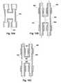
- FIGS. 9A-9Cillustrate a four-way valve that may be used to implement certain embodiments of the present invention.
- FIGS. 10A-10Cillustrate another four-way valve that may be used to implement certain embodiments of the present invention.
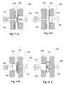
- FIG. 11Ais a side view of a mechanism for actuating the valves of FIGS. 9A-9C and 10 A- 10 C in a first position.
- FIG. 11Bis a top view of the mechanism for actuating the valves of FIGS. 9A-9C and 10 A- 10 C in the first position of FIG. 11 A.
- FIG. 11Cis a side view of the mechanism for actuating the valves of FIGS. 9A-9C and 10 A- 10 C in a second position.
- FIG. 11Dis a top view of the mechanism for actuating the valves of FIGS. 9A-9C and 10 A- 10 C in the second position of FIG. 11 C.
- FIG. 12Ais an illustration of functional components of a control system that may be used to control certain embodiments of the invention.
- FIG. 12Bis an illustration of the use of a sound sensor to sense air infiltration without requiring the direct sensing of a presence of air, such as is required by an ultrasonic air sensor.
- FIG. 13is an illustration of a portion of a blood circuit in which some other fluid is added for testing purposes and either subsequently rejected or subsequently supplied to the patient.
- FIG. 14is an illustration of how additional air sensors can be added to a blood circuit to reduce the quantity of blood that must be displaced for a test.
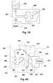
- FIG. 15is an illustration of a blood line for use with certain embodiments of the invention.
- FIG. 16is an illustration of an infusion system with leak detection according to an embodiment of the invention.
- a source of fluid 120supplies fluid to a drive/negative pressure device 100 that does at least two things: it moves the fluid to the patient and it selectively generates negative pressure. It may also incorporate, or be connected with, a treatment process 130 , for example a hemofiltration, hemodialysis, hemodiafiltration, or other blood treatment process.
- a fluid circuitconnects the drive/negative pressure device 100 to an air sensor 105 , which is in turn connected to a tested fluid circuit 110 whose leak-integrity must be assured. Finally, fluid is introduced into a patient 115 .
- the drive/negative pressure device 100may be transposed with the air sensor 105 , as long as it is assured that any leaks in the tested circuit 110 will arrive at at least one air sensor. Air sensors may be arranged in the tested circuit as well.
- the source of fluid 120is most likely blood from the patient 115 , as would be the case for an extracorporeal blood treatment process such as hemofiltration or dialysis. That is, the circuit 120 , 100 , 105 , 110 , may be a two-access draw/return circuit with some sort of treatment process 130 connected with it. However, the source of fluid could also be a storage vessel in a single access circuit or a quantity of blood being transfused or infused.
- the essential feature of the circuit of FIG. 1is that it is a supply circuit generally introducing fluid to the patient 115 .
- the air sensor 105detects air bubbles in the tested circuit when the flow of fluid is reversed in at least a portion of the tested circuit 110 by the inducement of negative pressure in the tested circuit 110 by the drive/negative pressure device 100 .
- the tested circuit 110may include any part of an extracorporeal treatment circuit where there is ordinarily a positive pressure applied to the fluid (blood, in that case) such that a leak in the tested circuit 110 would result in a loss of blood.
- the drive/negative pressure device 100generates a negative pressure on some intermittent schedule such that, at most times, fluid flows from the source 120 to the patient 115 .
- the negative pressureis temporarily generated in the tested circuit 110 .
- the negative pressurewill draw air through any leaks in the tested circuit 110 , which will appear as detectable air bubbles, triggering the air sensor 105 .
- one possible embodiment of the drive/negative pressure device 100is simply a reversible pump 200 .
- the pump 200could be, for example, a peristaltic pump whose direction of rotation can be reversed. It could be any type of pump that can be reconfigured, such as by rotating a drive in a reverse direction, to reverse flow.
- the flow-reversal effect of this embodimentproduces a negative pressure in the tested circuit 110 thereby drawing air into it and permitting detection of loss of integrity by the air sensor 105 .
- FIGS. 3 and 4another possible embodiment of the drive/negative pressure device 100 is a pair of pumps 230 , 235 and 240 , 245 .
- a parallel configuration 232only one pump 230 , 235 is actuated at a time, while the other 230 , 235 blocks flow while it is idle to prevent short-circuiting.
- a series configuration 242only one pump 240 , 245 is active at a time while the idle pump 240 , 245 permits blood to flow through it.
- the flow reversal caused by both embodimentshas the same effect as the embodiment of FIG. 2 .
- FIG. 5still another possible embodiment of the drive/negative pressure device 100 employs a single pump 255 that pumps in a single direction.
- a four-way valve 260transposes the input 256 and output 257 between the source of fluid 120 and the patient 115 such that a flow reversal results, as in the embodiments of FIGS. 2-4.
- a treatment process 130is arranged in series with the pump 255 .
- FIG. 6Astill another possible embodiment of the drive/negative pressure device 100 employs a single pump 270 that pumps in a single direction. Downstream of the pump 270 , a bladder 280 forms part of the continuous exiting blood circuit.
- the bladder 280may be expanded by a vacuum applied to a rigid casing 275 , for example by a suction device such as a vacuum pump 285 .
- the vacuum pump 285may incorporate ballast because of the less-than-unity duty cycle of the negative pressure inducement cycle. Rapid expansion of the bladder 280 causes a negative pressure in the tested circuit with an effect that is generally similar to that of the foregoing embodiments.
- the pump 270may or may not be deactivated.
- an alternative device for creating a negative pressureis a syringe 279 with a cylinder 278 and piston 276 driven by an automatic actuator 277 .
- a valvenot shown
- a blood processing machine 700processes blood supplied to it from a patient 710 via a leak detection device 705 .
- the blood processing machine 700may be any type of device including hemodialysis, hemofiltration, hemodiafiltration, blood and blood component collection, plasmaphresis, aphresis, and blood oxygenation.
- the leak detection device 705is configured such that blood flows as indicated by the arrows 706 and 707 .
- the leak detection device 705repeatedly generates a negative pressure in a return side 708 of the blood circuit thereby drawing air into that part of the circuit. This air can then be detected in various ways according to the way the blood processing machine 700 and/or leak detector device 705 are constructed.
- the leak detection device 705can be added to any type of conventional or as yet unknown type of blood processing machine to provide return side leak detection.
- the leak detection device 705is shown at 720 .
- the latterincludes a circuit with a four-way valve 722 and an air sensor 724 .
- a circuitis formed joining draw 707 and return 708 lines from the patient with the corresponding lines 702 and 703 of the blood processing machine through the four-way valve 722 .
- the four-way valve 722reverses the blood flow on the patient-side of the circuit without affecting the direction of blood flow through the blood processing machine 700 .
- An air sensor 724detects air in either the draw line 707 during forward operation and in the return line 708 during reverse operation.
- an alarmmay be actuated or the circuit may be clamped to halt blood flow, thereby triggering a malfunction response in the blood processing machine 700 as illustrated in detail in the particular embodiment of FIG. 7 E.
- the air sensor 724is not essential for practicing the invention if an air sensor is located in the blood processing machine 700 . In that case, control of the leak detection device 720 would have to insure that enough fluid is displaced to permit detection by the air sensor in the blood processing machine 700 .
- a leak detection device 730which can be added to an infusion pump 725 , includes an automatic syringe or reverse pump 735 and an air sensor 740 .
- a controller(not shown) causes the syringe or reverse pump 735 to reverse the flow through a circuit 737 leading to the patient 710 automatically.
- the air sensor 740detects any air drawn into the circuit 737 caused by any leaks.
- the same air sensor 740can detect any leaks upstream of it at times when the syringe, or reverse pump 735 , is not actuated.
- the syringe or reverse pump 735may be replaced by any suitable device such as that of FIG. 6A or 6 B, a diaphragm pump, or any other suitable mechanism for creating a negative flow in a tested circuit.
- the infusion pump 725itself may provide a mechanism for line testing if the pump within is made reversible as illustrated the embodiment of FIG. 7 D.
- an infusion pump 744draws fluid from a reservoir 743 via a pump 742 .
- An air sensor 746detects any bubbles in the fluid stream.
- a controller 741periodically reverses direction drawing air into the circuit 747 , which can be detected during the reverse operation and responded to by an alarm, shutdown, or other appropriate action.
- a blood processing machine 745 and leak detection device 750are interconnected as discussed with reference to FIG. 7 A.
- the blood processing machine 745contains a pump 775 and a filter or dialyzer 780 .
- the leak detection devicecontains a four-way valve 782 , which transposably interconnects the draw and return lines 751 of the blood processing machine 745 and the draw and return lines 752 of the patient 710 access.
- a controller 778periodically and automatically switches the four-way valve 782 , thereby causing air to enter any leaks in a return line and to be detected by an air sensor 776 .
- the controllermonitors the air sensor and may respond by actuating a clamp 777 and/or triggering an alarm 779 . Actuating the clamp 777 can be used to trigger a malfunction response by the blood processing machine 745 , which may have, for example, a pressure switch that would be activated by a clamped line.
- leak detection featuresare built combined with those of a blood processing machine to form an integrated leak detecting blood processing machine 783 .
- the lattercontains air sensors 760 and 770 , a filter 780 , and a reversible pump 775 , the latter being one mechanism for reversing flow to test the return circuit as discussed above in connection with other embodiments.
- two air sensors 760 and 770may quickly detect any leaks in draw and return accesses 762 and 763 when the pump is driven in forward and reverse directions, respectively.
- FIG. 7Fcontains air sensors 760 and 770 , a filter 780 , and a reversible pump 775 , the latter being one mechanism for reversing flow to test the return circuit as discussed above in connection with other embodiments.
- two air sensors 760 and 770may quickly detect any leaks in draw and return accesses 762 and 763 when the pump is driven in forward and reverse directions, respectively.
- the 7Falso contains an additional leak detection feature by defining a funnel 790 at the bottom of an enclosure housing a housed portion 784 of a blood circuit 764 with a fluid detector 785 at the bottom of the funnel 790 . Any leaks occurring in the housed portion 784 will be directed by the funnel 790 toward the fluid detector 785 .
- the fluid detector 785may be any suitable device for detecting blood, for example, a continuity tester.
- the fluid detector 785may be linked to the same alarm system as the air sensors 760 and 770 and be responded to in the same manner as discussed in connection with any of the embodiments described herein.
- a reservoir 805 of fluid to be infusedis pumped through an infusion pump 800 .
- the infusion pumphas a pump 830 , a four-way valve 810 , and one or more air sensors 803 .
- the four-way valve 810is set to infuse fluid from the reservoir 805 to the patient 840 .
- the four-way valve 810is controlled to reverse periodically to check for leaks.
- the four-way valve 810is connected such that fluid (which may include blood) flows back toward the one or more air sensors 803 indicating a leak.
- an example of a two-access blood processing system 300(illustrated as one for performing a hemofiltration or dialysis) combines a conventional blood processing machine (shown as a hemofiltration or dialysis machine) 301 with a venous disconnect sensor device 303 .
- the blood processing machine 301may be of standard design with a separate venous disconnect sensor device 303 connected to it to provide the functionality of the embodiment of FIG. 1 .
- the separate venous disconnect device 303allows retrofit of conventional blood processing machine 301 to provide the safety benefits of the invention.
- the blood processing machine 301contains a dialyzer or hemofilter 305 , which filters the blood passing through it.
- the dialyzer or hemofilter 305contains connections 355 and 356 to a waste fluid or dialysate circuit and arterial 361 and venous 362 connections of a treatment circuit 302 .
- a pump 310which is illustrated by a peristaltic pump, pumps blood through the dialyzer or hemofilter 305 , draws blood from the patient 335 , and returns blood to the patient 335 .
- Bloodpasses through the dialyzer or hemofilter 305 in one direction through a four-way valve 315 and then into a venous access 341 into the patient 335 . Blood is drawn from an arterial access 340 , passes through the four-way valve 315 , and is supplied to the pump 310 .
- the blood processing machine 301includes a venous return air sensor 320 located near the outlet of the dialyzer or hemofilter 305 in the treatment circuit 302 .
- the latterdetects any air in the blood prior to the blood being returned to the patient.
- the venous return air sensor 320is standard on blood processing machines such as the hemofiltration and dialysis machine 301 and may be any type of air detector. For example, it may be an ultrasonic bubble detector as commonly used for detecting leaks in blood processing equipment.
- a venous line clamp 325selectively cuts off flow downstream of the venous return air sensor 320 as standard on blood processing equipment.
- the draw line air sensor 345detects air in the arterial line downstream of the four-way valve 315 and upstream of the pump 310 .
- the four-way valve 315is switched to a reverse-flow position to cause blood to be drawn through venous access 341 and returned through the arterial access 340 .
- the configuration of FIGS. 8A and 8Bis instated only temporarily to cause air to infiltrate the venous circuit 342 through any leaks or disconnections in the venous circuit 342 .
- the air infiltrationmay then be detected by the air sensor 345 .
- the disclosed embodimentneed not have the air sensor 345 , but could rely for testing the venous circuit 342 on the air sensor 320 if the blood processing machine 301 has one. The only requirement would be that the flow be reversed long enough to displace any air bubbles from the leak to a point beyond the four-way valve 315 so that the pump will convey the air bubbles to the air sensor 320 .
- the line clamp 322is actuated shutting down flow through it and triggering a safety shutdown in the blood processing machine 301 .
- a safety mechanismthat when flow through the blood processing machine 301 is halted, because of a fault like a crushed line for example, a venous pressure monitor 350 is triggered due to a resulting rise in venous pressure. This causes the blood processing machine 301 to stop the pump 310 , set off an alarm, and clamp venous line clamp 325 .
- the venous disconnect sensor device 303is provided with an alarm 330 , such as an audio and/or visual signal to alert an operator to the shutdown.
- the venous disconnect sensor device 303may be connected to and used with a variety of different blood processing machines. Alternatively, its functionality may be integrated in any such machine. Also note that although the alarm event was described in the above embodiments as being triggered by a venous pressure monitor in the blood processing machine 301 , it could be configured such that the air sensor 345 triggers an alarm directly.
- the entire tested blood circuit 110 of FIG. 1 and an entire blood circuit 311 (FIG. 8A) of the two-access hemofiltration system 300may form a disposable unit.
- Another desirable attribute of the components of a blood circuitis that it be hydraulically continuous, that is, that it provide no dead spaces that could cause stagnation of some of the blood flow.
- Another sometimes-beneficial feature of the componentsis that they be free from surfaces that rub together or have potentially stagnant capillary spaces such as seals. Together, these cost and hydraulic continuity requirements can impose significant constraints on the design of the four-way valve 315 .
- a complete blood processing system with leak detection 1001may conform to the details of the embodiment of FIGS. 8A and 8B.
- the line clamp 322 of FIGS. 8A and 8Bmay be omitted.
- the air sensor 345may be omitted, if desired, although it may provide an advantage of making it possible to detect leaks earlier.
- Components of FIG. 8Cperform essentially the same functions as the identically-labeled components of FIGS. 8A and 8B and are therefore not discussed further.
- a four-way valve body 405is formed of a compliant injection moldable polymer.
- the valve body 405has four ports 411 , 412 , 413 , and 414 .
- Each porthas a flanged portion, for example as indicated at 410 , permitting tubing to be inserted and bonded to the valve body 405 .
- Each port 411 , 412 , 413 , and 414may be selectively joined to either of two adjacent ports by forcing an anvil-edge 415 against the center of the valve body 405 in one of two orthogonal directions as shown in FIGS. 9B and 9C.
- FIG. 9B and 9CIn FIG.
- the anvil-edgeis pressed in a first direction joining ports 411 and 412 and simultaneously joining ports 413 and 414 .
- the anvil-edgeis pressed in a second direction joining ports 411 and 414 and simultaneously joining ports 412 and 413 .
- the flow passages form by pinching the valve body 405are free of dead flow zones in both configurations.
- a valve body 430is formed in the shape of an “H.”
- an anvil-edgeis perpendicular to the first orientation and pinches the bridge to bisect it and form two parallel channels 460 .
- the anvil-edge 450pinches the H-shaped bridge 455 longitudinally along the centerline of the crossing line 455 of the “H” to form mirror image U-shaped channels 457 .
- the anvil edges 415 , 450may be actuated by solenoids.
- solenoidsReferring now to FIGS. 11A-11D, one way to activate both orientations of the anvil edge 405 / 415 , 450 with a single solenoid is by disposing two perpendicular anvils 510 and 515 on opposite sides of the valve body 540 .
- One anvil 515may be urged toward the valve body 540 by a spring 550 while the other is forced by the solenoid 560 .
- the solenoid 560is retracted, only the spring-urged anvil 515 deforms the valve body 540 .
- FIG. 11Ashows the spring urged anvil 515 is pressed along the bridge (parallel to the length of the bridge of the “H”) as viewed from the side and FIG. 11B shows the same configuration as viewed from the top.
- FIG. 11Cshows the solenoid urged anvil 510 pressed across and bisecting the bridge of the “H” as viewed from the side and FIG. 11D shows the same configuration as viewed from the top.
- Support tables 520 and 525provide support for parts of the valve body 540 that are not otherwise supported by the anvils 510 and 515 .
- FIG. 1may be provided in a fully integrated system rather than as an add-on to a conventional blood processing machine 301 as illustrated in the embodiment of FIGS. 8A and 8B. That is, the components of the venous disconnect sensor device 304 may be integrated in the blood processing machine 301 as is readily apparent from the figure.
- the air sensors 320 and 345may be combined with other sensing mechanisms in a fuzzy logic circuit or network classifier to enhance the robustness and sensitivity of leak detection.
- the inventive techniquemay be combined, for example, with fluid sensing as described in PCT application US98/19266, combined with venous pressure monitoring as outlined in International Standard IEC 60601-2-16.
- a control mechanism for an embodiment of the inventionincludes a controller 601 , which could be a programmable microprocessor, mechanical, or electromechanical controller.
- the controller 601is connected to receive inputs from an air sensor 604 and, optionally, other sensors 607 .
- the controller 601is also connected to control an alarm output 606 , a pump 602 , and a four-way valve 603 .
- the controller 601may control other types of drive/negative pressure devices 100 as should be clear from the present disclosure.
- the other sensors 607may include any (or none) of the fluid detectors and pressure sensors or any other sensors including those of the prior art.
- any, or all, of the sensor inputsmay be used in combination or alone to trigger an alarm state, preferably one accompanied by shutdown of the pump 602 .
- the air sensor 604may be any kind of sensor capable of detecting either the intrusion of air into a circuit or the presence of air in the circuit. Air infiltrating a line may create sound for example, as bubbles 683 are generated by the infiltration. Such a sound may be detected with, for example, an audio sensor such as a hydrophone 684 . A signal from a hydrophone 684 could be classified by an audio pattern recognition engine programmed into the controller 601 to screen out other sounds. In such a case, in the embodiments discussed above, air does not need to be drawn all the way to the air sensor 604 for infiltration to be detected; rather the audio signals may travel through the lines 682 in the fluid media to the sensor 684 .
- a hydrophonemay be detect sounds without being immersed in the fluid itself, as long as appropriate acoustic measures are taken to minimize attenuation through any barriers.
- Other types of disturbances or machine-recognizable featuresmay form a basis for detecting air infiltration such as optical, vibrational, chemical, etc.
- controller 601need not be the ultimate originator of command signals for the reversing (or negative pressure) cycles. So, for example, a signal for triggering the reversing (negative pressure) cycles could originate from a different source, for example a conventional blood processing system and be converted into a control signal by a final control (e.g. 601 ) to govern the reversing (negative pressure) cycle. Such an embodiment would be well within the scope of the invention as claimed below.
- the controller 601may also be responsible for controlling the timing of the periodic flow reversals.
- the pump 602may be configured to output encoder pulses to the controller 601 to allow the controller 601 to cumulate the volume of blood displaced in a given direction.
- the system of FIGS. 8A and 8Bpumps blood from the arterial access 340 processes it, and returns treated blood to the patient through a venous access 341 .
- the peristaltic pump, 310it is possible by counting the number of rotations of the pump to determine accurately the volume of blood displaced.
- a maximum tolerable blood lossmay be determined and used to control the periodic negative pressure cycles, for example in the hemofiltration system 300 . Note that in determining maximum limits, due consideration must be given to the fact that some of the patient's blood is already outside of his/her body in the circuit of the machine.
- the period of the flow reversal cyclescan be set to a value that is no greater than a ratio of the maximum allowable blood volume loss to the volume flow rate of the blood.
- the period of the flow reversal cyclesshould be no greater than one minute.
- the period between cyclescan be determined by calibrated timing, by direct measurement of mass or volume flow, or by other means effective to insure the amount of blood does not go beyond some safe limit.
- each negative pressure cycleis best determined by how long it takes to draw the entire quantity of blood in the circuit between the terminal end of the patient's venous access and a point where it is inevitable that the infiltrated air will reach an air detector (e.g., 345 ). In a system with a four-way valve, this may be the point where the air is just beyond the four-way valve, where the blood runs through the circuit in the same direction irrespective of the position of the four-way valve. For example, in the embodiment of FIGS.
- the pumpwill insure that it gets to the air sensor 345 once it is on the treatment circuit 302 side of the four-way valve 315 , which only runs in direction.
- the duration of the negative pressure cycleneed only insure that a leak at the most remote end would cause air bubbles to be drawn all the way to an air sensor.
- control protocolsalthough not required, are desirable. These protocols may be implemented by suitably calibrated timing of control signals, by counting pump revolutions, by direct measurement of blood flow volume, or any other suitable technique.
- the maximum allowable blood losswhich may be used to determine the maximum time between leak test cycles, may be made a programmable value that can be entered in the controller 601 .
- Each patientmay be evaluated and a maximum threshold established specifically for him/her.
- the controllercould be connected to an electronic scale, which generates a maximum tolerable blood loss value based on the patient's weight.
- a peristaltic pumpwas disclosed, this is only an example and it is clear that a variety of different types of pumps may be used with the invention.
- a diaphragm or turbine pumpmay also be used in place of any of the pumps disclosed.
- a four-way valve, a reversible pump, an expanding bladder, and connected pairs of pumpswere described as mechanisms for reversing flow, it is clear that other mechanisms can also be employed.
- Each of the examples of a pump and a valve or reversible pump, or pump combinationsamounts to a different reversible conveyance. Note also that it is possible to practice the invention, as indicated in the discussion of FIGS.
- hemofiltration or dialysis application of the inventionwas described, it is clear the invention is applicable to many different systems in which blood is circulated outside the body.
- the systemmay be used to avoid waste of blood or insure the satisfaction of a critical need, during transfusion.
- Some other examples of applicationsare hemodialysis, hemofiltration, hemodiafiltration, blood and blood component collection, plasmaphresis, aphresis, and blood oxygenation.
- a fluid other than bloodmay be drawn or injected for line-testing purposes rather than relying solely on blood drawn from the return line. This may be useful in instances where the venous access cannot supply a great deal of blood.
- sterile fluid from a reservoir 601may be allowed to flow into a junction 605 through a cutoff valve 610 when the flow is reversed or a negative pressure generated. Any leaks would be detectable in the fluid, as they are detected, as discussed above.
- the only blood that need be drawn through a draw access 615is the volume necessary to fill the circuit 620 between the remote terminus 625 of the access and the junction 605 .
- a control system 630may open the cutoff valve 610 permitting fluid from the reservoir 601 to enter the junction 605 only after at least a sufficient volume of blood had been drawn from the remote terminus 625 to fill the circuit between the remote terminus 625 and the junction 605 .
- a volume of fluid, possibly along with blood,would then be drawn at least sufficient to fill the circuit between the point where it is inevitable that the air will arrive at an air sensor 640 .
- the volumemight be the volume of the circuit from the remote terminus 625 right up to (or sufficiently near) the air sensor 640 to be detected.
- the fluidmay be drained to a waste collection container 635 or returned to the patient.
- the former optionmay be implemented through a suitable flow diverter mechanism 637 such as used to let fluid in.
- a single air sensoris shown. It is clear that multiple air sensors may be used in a single line and spaced apart by an equal volume of displaced fluid/blood so that the volume of blood/fluid that must be pumped in reverse can be reduced. Thus, referring to FIG. 14, if a two air sensors 650 are used in a given circuit portion 655 rather than only one, the amount of fluid/blood that has to be displaced in the circuit in order to test it fully for leaks can be reduced substantially by half.
- a blood line 655has two access ends 660 and 665 adapted to be connected to a patient for draw and return of blood.
- Two filter ends 670 and 675are connected by a valve portion 680 to the access ends 660 and 665 and adapted to be connected to a filter or other treatment device (not shown).
- the filter ends 670 and 675may be connected to a filter (not shown) at the point of manufacture and sealed and sterilized with the entire blood line shown.
- the valve portion 680preferably, is a blood contact portion of a complete flow diverting device that may be, for example, the valve body parts 405 , 430 , 540 of the four-way valves illustrated in FIGS.
- the valve portion 680switches the direction of the flow of blood between the access ends 660 and 665 .
- the bloodline 655also has a portion 656 adapted to be driven by a pump, such as a peristaltic pump (not shown).
- the bloodline of FIG. 15may be a replaceable device that is packaged with instructions 667 explaining how it may be used with a blood processing machine such as any of the embodiment discussed above. It may be configured to provide the fluid conveyance line for both the blood processing machine and leak detection device portions of any of the above embodiments, such as embodiments configured along the lines of FIG. 7A or complete systems like.
- the blood line 655has only the basic elements, and in a practical implementation would be expected to include one or more of the following: injection sites, luer connectors, drip chambers, transducer protectors, manual line clamps, access lines, access needles, dialyzers, filters, protective caps, etc.
- the entire blood lineis manufactured and then sterilized, for example, by gamma rays, steam, or other means.
- inventive leak detection method and deviceare applied to extracorporeal blood circuits
- the inventionhas other applications as well.
- circuits used for infusion of costly (or time-critical) drugsmay be monitored using the invention.
- the negative pressuredraws air into the liquid in the line if there are any leaks in the line.
- the airis detected by the air detector 920 and the leak is revealed.
- Any liquid conveyance systemmay be tested in this way, as long as a negative pressure can be generated selectively using any of the techniques (or any others) as discussed above.
- the source and sinkmay be identical.
- the systemmight circulate liquid through a processing system such as a heat exchanger or a reaction processor with a catalyst or other such processing system.
- leaksare betrayed by the detection of a presence of air into the tested line
- other techniquesare possible in other embodiments of the invention. For example, rather than detect a presence of air, it is possible to detect the infiltration of the air as it occurs.
- an acoustic signalmay be generated by bubbles as they are drawn into the tested circuit. This signal may be detected by an acoustic sensor.
- air bubbles flowing through the linemay be detected by other means such as an acoustic signal of bubbles passing by an acoustic sensor.
- Various velocimetry techniquesare affected by air, for example vortex shedding velocimeter, orifice plates, and other such devices.
- the presence of airmay be detected by optical means as well.
Landscapes
- Health & Medical Sciences (AREA)
- Heart & Thoracic Surgery (AREA)
- Vascular Medicine (AREA)
- Biomedical Technology (AREA)
- Engineering & Computer Science (AREA)
- Anesthesiology (AREA)
- Cardiology (AREA)
- Hematology (AREA)
- Life Sciences & Earth Sciences (AREA)
- Animal Behavior & Ethology (AREA)
- General Health & Medical Sciences (AREA)
- Public Health (AREA)
- Veterinary Medicine (AREA)
- External Artificial Organs (AREA)
- Examining Or Testing Airtightness (AREA)
Abstract
Description
Claims (89)
Priority Applications (8)
| Application Number | Priority Date | Filing Date | Title |
|---|---|---|---|
| US09/900,362US6572576B2 (en) | 2001-07-07 | 2001-07-07 | Method and apparatus for leak detection in a fluid line |
| DE60237621TDE60237621D1 (en) | 2001-07-07 | 2002-07-08 | SYSTEM FOR THE DETECTION OF LEAKAGE POINTS IN A LIQUID CHANNEL |
| AU2002326340AAU2002326340A1 (en) | 2001-07-07 | 2002-07-08 | Method and apparatus for leak detection in a fluid line |
| PCT/US2002/021372WO2003006944A2 (en) | 2001-07-07 | 2002-07-08 | Method and apparatus for leak detection in a fluid line |
| US10/483,142US7087033B2 (en) | 2001-07-07 | 2002-07-08 | Method and apparatus for leak detection in a fluid line |
| AT02761044TATE480275T1 (en) | 2001-07-07 | 2002-07-08 | SYSTEM FOR DETECTING LEAKS IN A LIQUID LINE |
| JP2003512663AJP4118233B2 (en) | 2001-07-07 | 2002-07-08 | Method and apparatus for detecting fluid line leaks |
| EP02761044.3AEP1425063B2 (en) | 2001-07-07 | 2002-07-08 | System for leak detection in a fluid line |
Applications Claiming Priority (1)
| Application Number | Priority Date | Filing Date | Title |
|---|---|---|---|
| US09/900,362US6572576B2 (en) | 2001-07-07 | 2001-07-07 | Method and apparatus for leak detection in a fluid line |
Related Child Applications (2)
| Application Number | Title | Priority Date | Filing Date |
|---|---|---|---|
| US10/483,142Continuation-In-PartUS7087033B2 (en) | 2001-07-07 | 2002-07-08 | Method and apparatus for leak detection in a fluid line |
| US10483142Continuation-In-Part | 2002-07-08 |
Publications (2)
| Publication Number | Publication Date |
|---|---|
| US20030009123A1 US20030009123A1 (en) | 2003-01-09 |
| US6572576B2true US6572576B2 (en) | 2003-06-03 |
Family
ID=25412386
Family Applications (2)
| Application Number | Title | Priority Date | Filing Date |
|---|---|---|---|
| US09/900,362Expired - LifetimeUS6572576B2 (en) | 2001-07-07 | 2001-07-07 | Method and apparatus for leak detection in a fluid line |
| US10/483,142Expired - LifetimeUS7087033B2 (en) | 2001-07-07 | 2002-07-08 | Method and apparatus for leak detection in a fluid line |
Family Applications After (1)
| Application Number | Title | Priority Date | Filing Date |
|---|---|---|---|
| US10/483,142Expired - LifetimeUS7087033B2 (en) | 2001-07-07 | 2002-07-08 | Method and apparatus for leak detection in a fluid line |
Country Status (7)
| Country | Link |
|---|---|
| US (2) | US6572576B2 (en) |
| EP (1) | EP1425063B2 (en) |
| JP (1) | JP4118233B2 (en) |
| AT (1) | ATE480275T1 (en) |
| AU (1) | AU2002326340A1 (en) |
| DE (1) | DE60237621D1 (en) |
| WO (1) | WO2003006944A2 (en) |
Cited By (114)
| Publication number | Priority date | Publication date | Assignee | Title |
|---|---|---|---|---|
| US20030018290A1 (en)* | 2001-07-17 | 2003-01-23 | Brugger James M. | Hermetic flow selector valve |
| US20030126910A1 (en)* | 2002-01-04 | 2003-07-10 | Burbank Jeffrey H. | Method and apparatus for leak detection in blood circuits combining external fluid detection and air infiltration detection |
| US20030136181A1 (en)* | 2002-01-15 | 2003-07-24 | Fresenius Medical Care Deutschland Gmbh. | Method and device for detecting a leakage in a fluid system of a blood treatment apparatus |
| US20040030277A1 (en)* | 2000-11-02 | 2004-02-12 | Chf Solutions, Inc. | Method and apparatus for blood withdrawal and infusion using a pressure controller |
| US6695807B2 (en) | 2002-01-18 | 2004-02-24 | Dsu Medical, Inc. | Blood flow reversing system |
| US20040133145A1 (en)* | 2002-12-20 | 2004-07-08 | Hospal International Marketing Management Snc | Device and process for extracorporeal treatment by citrate anticoagulant |
| US20040243046A1 (en)* | 2001-07-07 | 2004-12-02 | Brugger James M. | Method and apparatus for leak detection in a fluid line |
| US20050131332A1 (en)* | 2003-11-05 | 2005-06-16 | Thomas Kelly | High convection home hemodialysis/hemofiltration and sorbent system |
| WO2005019416A3 (en)* | 2003-08-13 | 2005-11-10 | Moll Family Trust | Method and device for monitoring loss of body fluid and dislodgment of medical instrument from body |
| US7052480B2 (en)* | 2002-04-10 | 2006-05-30 | Baxter International Inc. | Access disconnection systems and methods |
| US20060130591A1 (en)* | 2004-12-21 | 2006-06-22 | Perkins, Corban Enterprises | Venous needle dislodgement sensor |
| US20060161094A1 (en)* | 2005-01-14 | 2006-07-20 | Utterberg David S | 3D clampable valve flow reversing system |
| US20070004996A1 (en)* | 2005-06-20 | 2007-01-04 | Lovejoy David A | Needle disengagement sensing mechanism |
| US20070010779A1 (en)* | 2005-07-07 | 2007-01-11 | Utterberg David S | Blood leak monitoring method and apparatus |
| US20070119508A1 (en)* | 2005-11-29 | 2007-05-31 | West Richard L | Fluid Flow Diversion Valve and Blood Collection System Employing Same |
| US20080108954A1 (en)* | 2006-11-02 | 2008-05-08 | Jean-Marie Mathias | Flow Controllers |
| US20080108955A1 (en)* | 2006-11-02 | 2008-05-08 | Blickhan Bryan J | Flow Controllers |
| US20080195060A1 (en)* | 2007-02-09 | 2008-08-14 | Baxter International Inc. | Optical access disconnection systems and methods |
| US20080195021A1 (en)* | 2007-02-09 | 2008-08-14 | Baxter International Inc. | Acoustic access disconnection systems and methods |
| US20080203023A1 (en)* | 2002-06-06 | 2008-08-28 | Nxstage Medical, Inc. | Last-chance quality check and/or air/pathogen filtger for infusion systems |
| US20080214979A1 (en)* | 2003-11-07 | 2008-09-04 | Nxstage Medical, Inc. | Methods and Apparatus For Leak Detection in Blood Processing Systems |
| US20080230450A1 (en)* | 2005-01-07 | 2008-09-25 | Burbank Jeffrey H | Filtration System for Preparation of Fluids for Medical Applications |
| US20090012456A1 (en)* | 2007-07-05 | 2009-01-08 | Baxter International Inc. | Dialysis system having disposable cassette |
| US20090076434A1 (en)* | 2007-09-13 | 2009-03-19 | Mischelevich David J | Method and System for Achieving Volumetric Accuracy in Hemodialysis Systems |
| US20090082676A1 (en)* | 2007-09-21 | 2009-03-26 | Baxter International Inc. | Acoustic access disconnect detection system |
| US20090088675A1 (en)* | 2007-10-01 | 2009-04-02 | Baxter International Inc. | Fluid and air handling in blood and dialysis circuits |
| US20090101577A1 (en)* | 2007-09-28 | 2009-04-23 | Fulkerson Barry N | Methods and Systems for Controlling Ultrafiltration Using Central Venous Pressure Measurements |
| US20090101576A1 (en)* | 2007-10-22 | 2009-04-23 | Baxter International Inc. | Priming and air removal systems and methods for dialysis |
| US20090101552A1 (en)* | 2007-09-25 | 2009-04-23 | Fulkerson Barry N | Manifolds for Use in Conducting Dialysis |
| US20090107902A1 (en)* | 2007-10-24 | 2009-04-30 | Baxter International Inc. | Personal hemodialysis system |
| US20090124963A1 (en)* | 2007-11-09 | 2009-05-14 | Baxter International Inc. | Balanced flow dialysis machine |
| US20090182263A1 (en)* | 2006-04-07 | 2009-07-16 | Burbank Jeffrey H | Filtration system for preparation of fluids for medical applications |
| US20090211975A1 (en)* | 2003-01-07 | 2009-08-27 | Brugger James M | Batch Filtration System for Preparation of Sterile Fluid for Renal Replacement Therapy |
| US20090218535A1 (en)* | 2008-02-27 | 2009-09-03 | Andres Pasko | Flow controllers for fluid circuits |
| US20100022934A1 (en)* | 2008-07-25 | 2010-01-28 | Baxter International Inc. | System and method for detecting access disconnection |
| WO2010044801A1 (en)* | 2008-10-17 | 2010-04-22 | Emory University | Systems and methods for preventing mistransfusion |
| US20100116740A1 (en)* | 2007-11-29 | 2010-05-13 | Barry Neil Fulkerson | Priming System and Method for Dialysis Systems |
| US7744553B2 (en) | 2003-12-16 | 2010-06-29 | Baxter International Inc. | Medical fluid therapy flow control systems and methods |
| US20100184198A1 (en)* | 2009-01-16 | 2010-07-22 | Joseph Russell T | Systems and Methods of Urea Processing to Reduce Sorbent Load |
| US20100280430A1 (en)* | 2007-10-04 | 2010-11-04 | Gambro Lundia Ab | Infusion apparatus |
| US20110034850A1 (en)* | 2008-04-15 | 2011-02-10 | Joensson Lennart | Blood treatment apparatus and method |
| EP1872813B1 (en)* | 2006-06-30 | 2011-08-17 | Shibuya Kogyo Co., Ltd | Dialysis device |
| US8033157B2 (en) | 2007-10-01 | 2011-10-11 | Baxter International Inc. | Medical fluid air bubble detection apparatus and method |
| US8038639B2 (en) | 2004-11-04 | 2011-10-18 | Baxter International Inc. | Medical fluid system with flexible sheeting disposable unit |
| US8040493B2 (en) | 2007-10-11 | 2011-10-18 | Fresenius Medical Care Holdings, Inc. | Thermal flow meter |
| US8114288B2 (en) | 2007-11-29 | 2012-02-14 | Fresenlus Medical Care Holdings, Inc. | System and method for conducting hemodialysis and hemofiltration |
| US8114043B2 (en) | 2008-07-25 | 2012-02-14 | Baxter International Inc. | Electromagnetic induction access disconnect sensor |
| US8240636B2 (en) | 2009-01-12 | 2012-08-14 | Fresenius Medical Care Holdings, Inc. | Valve system |
| US8475399B2 (en) | 2009-02-26 | 2013-07-02 | Fresenius Medical Care Holdings, Inc. | Methods and systems for measuring and verifying additives for use in a dialysis machine |
| US8529490B2 (en) | 2002-04-10 | 2013-09-10 | Baxter International Inc. | Systems and methods for dialysis access disconnection |
| US8535522B2 (en) | 2009-02-12 | 2013-09-17 | Fresenius Medical Care Holdings, Inc. | System and method for detection of disconnection in an extracorporeal blood circuit |
| US20130261529A1 (en)* | 2004-12-03 | 2013-10-03 | Gambro Uf Solutions, Inc. | Extracorporeal blood treatment and system having reversible blood pumps |
| US8597505B2 (en) | 2007-09-13 | 2013-12-03 | Fresenius Medical Care Holdings, Inc. | Portable dialysis machine |
| US8608658B2 (en) | 2002-01-04 | 2013-12-17 | Nxstage Medical, Inc. | Method and apparatus for machine error detection by combining multiple sensor inputs |
| US20140088482A1 (en)* | 2012-09-25 | 2014-03-27 | Fresenius Medical Care Holdings, Inc. | Blood Flow Reversal Valves and Related Systems and Methods |
| US8920356B2 (en) | 2002-04-10 | 2014-12-30 | Baxter International Inc. | Conductive polymer materials and applications thereof including monitoring and providing effective therapy |
| US9114217B2 (en) | 2011-08-19 | 2015-08-25 | Hospira, Inc. | Pattern recognition system and method for the detection of stuck fluid droplets in a fluid delivery line of an infusion system |
| US9138536B2 (en) | 2008-04-01 | 2015-09-22 | Gambro Lundia Ab | Apparatus and a method for monitoring a vascular access |
| US9157786B2 (en) | 2012-12-24 | 2015-10-13 | Fresenius Medical Care Holdings, Inc. | Load suspension and weighing system for a dialysis machine reservoir |
| US9199022B2 (en) | 2008-09-12 | 2015-12-01 | Fresenius Medical Care Holdings, Inc. | Modular reservoir assembly for a hemodialysis and hemofiltration system |
| US9308307B2 (en) | 2007-09-13 | 2016-04-12 | Fresenius Medical Care Holdings, Inc. | Manifold diaphragms |
| US9328969B2 (en) | 2011-10-07 | 2016-05-03 | Outset Medical, Inc. | Heat exchange fluid purification for dialysis system |
| US9354640B2 (en) | 2013-11-11 | 2016-05-31 | Fresenius Medical Care Holdings, Inc. | Smart actuator for valve |
| US9358331B2 (en) | 2007-09-13 | 2016-06-07 | Fresenius Medical Care Holdings, Inc. | Portable dialysis machine with improved reservoir heating system |
| US9383288B2 (en) | 2008-06-26 | 2016-07-05 | Gambro Lundia Ab | Method and device for processing a time-dependent measurement signal |
| US9402945B2 (en) | 2014-04-29 | 2016-08-02 | Outset Medical, Inc. | Dialysis system and methods |
| US9433720B2 (en) | 2013-03-14 | 2016-09-06 | Fresenius Medical Care Holdings, Inc. | Universal portable artificial kidney for hemodialysis and peritoneal dialysis |
| US9433356B2 (en) | 2009-06-26 | 2016-09-06 | Gambro Lundia Ab | Devices, a computer program product and a method for data extraction |
| US9486590B2 (en) | 2014-09-29 | 2016-11-08 | Fenwal, Inc. | Automatic purging of air from a fluid processing system |
| US9545469B2 (en) | 2009-12-05 | 2017-01-17 | Outset Medical, Inc. | Dialysis system with ultrafiltration control |
| US9649420B2 (en) | 2014-09-12 | 2017-05-16 | Easydial, Inc. | Portable hemodialysis machine and disposable cartridge with flow sensor |
| US9717840B2 (en) | 2002-01-04 | 2017-08-01 | Nxstage Medical, Inc. | Method and apparatus for machine error detection by combining multiple sensor inputs |
| US9724459B2 (en) | 2011-08-15 | 2017-08-08 | Nxstage Medical, Inc. | Medical device leak sensing devices, methods, and systems |
| US9764074B1 (en) | 2002-07-19 | 2017-09-19 | Baxter International Inc. | Systems and methods for performing dialysis |
| US9895109B2 (en) | 2013-03-20 | 2018-02-20 | Gambro Lundia Ab | Monitoring of cardiac arrest in a patient connected to an extracorporeal blood processing apparatus |
| US9995611B2 (en) | 2012-03-30 | 2018-06-12 | Icu Medical, Inc. | Air detection system and method for detecting air in a pump of an infusion system |
| US10022498B2 (en) | 2011-12-16 | 2018-07-17 | Icu Medical, Inc. | System for monitoring and delivering medication to a patient and method of using the same to minimize the risks associated with automated therapy |
| US10035103B2 (en) | 2008-10-30 | 2018-07-31 | Fresenius Medical Care Holdings, Inc. | Modular, portable dialysis system |
| US10046112B2 (en) | 2013-05-24 | 2018-08-14 | Icu Medical, Inc. | Multi-sensor infusion system for detecting air or an occlusion in the infusion system |
| US10130746B2 (en) | 2003-01-07 | 2018-11-20 | Nxstage Medical, Inc. | Filtration system for preparation of fluids for medical applications |
| US10155082B2 (en) | 2002-04-10 | 2018-12-18 | Baxter International Inc. | Enhanced signal detection for access disconnection systems |
| US10166328B2 (en) | 2013-05-29 | 2019-01-01 | Icu Medical, Inc. | Infusion system which utilizes one or more sensors and additional information to make an air determination regarding the infusion system |
| US10189727B2 (en) | 2011-12-13 | 2019-01-29 | Nxstage Medical, Inc. | Fluid purification methods, devices, and systems |
| US10232103B1 (en) | 2001-11-13 | 2019-03-19 | Baxter International Inc. | System, method, and composition for removing uremic toxins in dialysis processes |
| US10342917B2 (en) | 2014-02-28 | 2019-07-09 | Icu Medical, Inc. | Infusion system and method which utilizes dual wavelength optical air-in-line detection |
| US10413654B2 (en) | 2015-12-22 | 2019-09-17 | Baxter International Inc. | Access disconnection system and method using signal metrics |
| US10430761B2 (en) | 2011-08-19 | 2019-10-01 | Icu Medical, Inc. | Systems and methods for a graphical interface including a graphical representation of medical data |
| US10463778B2 (en) | 2007-02-09 | 2019-11-05 | Baxter International Inc. | Blood treatment machine having electrical heartbeat analysis |
| US10463788B2 (en) | 2012-07-31 | 2019-11-05 | Icu Medical, Inc. | Patient care system for critical medications |
| US10596316B2 (en) | 2013-05-29 | 2020-03-24 | Icu Medical, Inc. | Infusion system and method of use which prevents over-saturation of an analog-to-digital converter |
| US10635784B2 (en) | 2007-12-18 | 2020-04-28 | Icu Medical, Inc. | User interface improvements for medical devices |
| US10656894B2 (en) | 2017-12-27 | 2020-05-19 | Icu Medical, Inc. | Synchronized display of screen content on networked devices |
| US10792414B2 (en) | 2013-03-14 | 2020-10-06 | Fresenius Medical Care Holdings, Inc. | Universal portable machine for online hemodiafiltration using regenerated dialysate |
| US10850024B2 (en) | 2015-03-02 | 2020-12-01 | Icu Medical, Inc. | Infusion system, device, and method having advanced infusion features |
| US10980929B2 (en) | 2014-09-12 | 2021-04-20 | Diality Inc. | Hemodialysis system with ultrafiltration controller |
| US10980431B2 (en) | 2009-12-28 | 2021-04-20 | Gambro Lundia Ab | Apparatus and method for prediction of rapid symptomatic blood pressure decrease |
| US11135360B1 (en) | 2020-12-07 | 2021-10-05 | Icu Medical, Inc. | Concurrent infusion with common line auto flush |
| US11246985B2 (en) | 2016-05-13 | 2022-02-15 | Icu Medical, Inc. | Infusion pump system and method with common line auto flush |
| US11278671B2 (en) | 2019-12-04 | 2022-03-22 | Icu Medical, Inc. | Infusion pump with safety sequence keypad |
| US11324888B2 (en) | 2016-06-10 | 2022-05-10 | Icu Medical, Inc. | Acoustic flow sensor for continuous medication flow measurements and feedback control of infusion |
| US11344668B2 (en) | 2014-12-19 | 2022-05-31 | Icu Medical, Inc. | Infusion system with concurrent TPN/insulin infusion |
| US11344673B2 (en) | 2014-05-29 | 2022-05-31 | Icu Medical, Inc. | Infusion system and pump with configurable closed loop delivery rate catch-up |
| US11454766B2 (en) | 2017-11-17 | 2022-09-27 | Senko Advanced Components, Inc. | Ultra-small form factor optical connector having dual alignment keys |
| US11525798B2 (en) | 2012-12-21 | 2022-12-13 | Fresenius Medical Care Holdings, Inc. | Method and system of monitoring electrolyte levels and composition using capacitance or induction |
| US11534537B2 (en) | 2016-08-19 | 2022-12-27 | Outset Medical, Inc. | Peritoneal dialysis system and methods |
| US11724013B2 (en) | 2010-06-07 | 2023-08-15 | Outset Medical, Inc. | Fluid purification system |
| US11826545B2 (en) | 2016-09-08 | 2023-11-28 | Fresenius Medical Care Holdings, Inc. | Optical blood detection system |
| US11883361B2 (en) | 2020-07-21 | 2024-01-30 | Icu Medical, Inc. | Fluid transfer devices and methods of use |
| US12201762B2 (en) | 2018-08-23 | 2025-01-21 | Outset Medical, Inc. | Dialysis system and methods |
| US12318528B2 (en) | 2020-10-30 | 2025-06-03 | Mozarc Medical Us Llc | Variable orifice fistula graft |
| US12350233B2 (en) | 2021-12-10 | 2025-07-08 | Icu Medical, Inc. | Medical fluid compounding systems with coordinated flow control |
| US12390565B2 (en) | 2019-04-30 | 2025-08-19 | Outset Medical, Inc. | Dialysis systems and methods |
| US12390567B2 (en) | 2005-01-07 | 2025-08-19 | Nxstage Medical, Inc. | Filtration system for preparation of fluids for medical applications |
| USD1091564S1 (en) | 2021-10-13 | 2025-09-02 | Icu Medical, Inc. | Display screen or portion thereof with graphical user interface for a medical device |
Families Citing this family (59)
| Publication number | Priority date | Publication date | Assignee | Title |
|---|---|---|---|---|
| US6890315B1 (en) | 2000-05-23 | 2005-05-10 | Chf Solutions, Inc. | Method and apparatus for vein fluid removal in heart failure |
| US6689083B1 (en)* | 2000-11-27 | 2004-02-10 | Chf Solutions, Inc. | Controller for ultrafiltration blood circuit which prevents hypotension by monitoring osmotic pressure in blood |
| US6773412B2 (en)* | 2001-04-13 | 2004-08-10 | Chf Solutions, Inc. | User interface for blood treatment device |
| US6796955B2 (en)* | 2002-02-14 | 2004-09-28 | Chf Solutions, Inc. | Method to control blood and filtrate flowing through an extracorporeal device |
| US6947131B2 (en)* | 2002-05-07 | 2005-09-20 | Chf Solutions, Inc. | Blood leak detector for extracorporeal treatment system |
| US7901419B2 (en)* | 2002-09-04 | 2011-03-08 | Allergan, Inc. | Telemetrically controlled band for regulating functioning of a body organ or duct, and methods of making, implantation and use |
| US7297270B2 (en)* | 2003-04-04 | 2007-11-20 | Chf Solutions, Inc. | Hollow fiber filter for extracorporeal blood circuit |
| JP4137751B2 (en)* | 2003-09-19 | 2008-08-20 | 日機装株式会社 | Blood purification equipment |
| US7671974B2 (en)* | 2003-10-29 | 2010-03-02 | Chf Solutions Inc. | Cuvette apparatus and system for measuring optical properties of a liquid such as blood |
| US7303540B2 (en) | 2004-04-26 | 2007-12-04 | Chf Solutions, Inc. | User interface for blood treatment device |
| JP4248463B2 (en)* | 2004-08-23 | 2009-04-02 | 日機装株式会社 | Blood purification equipment |
| JP4094600B2 (en)* | 2004-10-06 | 2008-06-04 | 日機装株式会社 | Blood purification equipment |
| EP1802363A1 (en)* | 2004-10-22 | 2007-07-04 | Cobe Cardiovascular, Inc. | Convertible extracorporeal blood perfusion systems |
| US20080161723A1 (en)* | 2006-09-06 | 2008-07-03 | Optiscan Biomedical Corporation | Infusion flow interruption method and apparatus |
| WO2007051118A2 (en) | 2005-10-25 | 2007-05-03 | Nxstage Medical, Inc | Safety features for medical devices requiring assistance and supervision |
| JP4798653B2 (en)* | 2005-11-18 | 2011-10-19 | 日機装株式会社 | Blood purification equipment |
| US8043206B2 (en) | 2006-01-04 | 2011-10-25 | Allergan, Inc. | Self-regulating gastric band with pressure data processing |
| US7798954B2 (en) | 2006-01-04 | 2010-09-21 | Allergan, Inc. | Hydraulic gastric band with collapsible reservoir |
| US7815588B2 (en)* | 2006-06-07 | 2010-10-19 | Paul Sakiewicz | Method and device for reversing lines in the procedure of hemodialysis |
| US7442575B2 (en)* | 2006-09-29 | 2008-10-28 | Texas Christian University | Method of manufacturing semiconductor nanowires |
| US9333293B2 (en)* | 2007-05-09 | 2016-05-10 | Acist Medical Systems, Inc. | Injector device, method, and computer program product for detecting a vacuum within a syringe |
| WO2008152810A1 (en)* | 2007-06-13 | 2008-12-18 | Kuraray Medical Inc. | Blood purification apparatus and method of confirming circuit continuity failure thereof |
| DE102007039581A1 (en)* | 2007-08-22 | 2009-02-26 | Fresenius Medical Care Deutschland Gmbh | Apparatus and method for monitoring access to a patient |
| US8221320B2 (en) | 2007-09-21 | 2012-07-17 | Baxter International Inc. | Access disconnect detection system |
| CN102006896B (en)* | 2008-04-15 | 2014-02-19 | 甘布罗伦迪亚股份公司 | blood processing device |
| US20100100026A1 (en)* | 2008-10-16 | 2010-04-22 | Fresenius Medical Care Holdings, Inc. | Wetness sensor utilizing passive resonant circuits |
| US20100185049A1 (en)* | 2008-10-22 | 2010-07-22 | Allergan, Inc. | Dome and screw valves for remotely adjustable gastric banding systems |
| US9370324B2 (en) | 2008-11-05 | 2016-06-21 | Fresenius Medical Care Holdings, Inc. | Hemodialysis patient data acquisition, management and analysis system |
| US8840541B2 (en) | 2010-02-25 | 2014-09-23 | Apollo Endosurgery, Inc. | Pressure sensing gastric banding system |
| US8939888B2 (en) | 2010-04-28 | 2015-01-27 | Apollo Endosurgery, Inc. | Method and system for determining the pressure of a fluid in a syringe, an access port, a catheter, and a gastric band |
| US20110270025A1 (en) | 2010-04-30 | 2011-11-03 | Allergan, Inc. | Remotely powered remotely adjustable gastric band system |
| EP2601985A4 (en)* | 2010-08-05 | 2015-10-07 | Nikkiso Co Ltd | BLOOD PURIFYING DEVICE, AND METHOD FOR FLUID LEAK INSPECTION IN SUCH A DEVICE |
| US8743354B2 (en) | 2010-09-07 | 2014-06-03 | Fresenius Medical Care Holdings, Inc. | Shrouded sensor clip assembly and blood chamber for an optical blood monitoring system |
| US9194792B2 (en) | 2010-09-07 | 2015-11-24 | Fresenius Medical Care Holdings, Inc. | Blood chamber for an optical blood monitoring system |
| US8517968B2 (en) | 2011-02-25 | 2013-08-27 | Fresenius Medical Care Holdings, Inc. | Shrouded sensor clip assembly and blood chamber for an optical blood monitoring system |
| GB201019228D0 (en)* | 2010-11-15 | 2010-12-29 | Corp | Dialysis device and method of dialysis |
| US9173988B2 (en) | 2010-11-17 | 2015-11-03 | Fresenius Medical Care Holdings, Inc. | Sensor clip assembly for an optical monitoring system |
| CN107307871B (en) | 2010-11-17 | 2020-04-28 | 弗雷泽纽斯医疗保健控股公司 | Sensor clip assembly for optical monitoring system |
| US8725435B2 (en) | 2011-04-13 | 2014-05-13 | Apollo Endosurgery, Inc. | Syringe-based leak detection system |
| USD725261S1 (en) | 2012-02-24 | 2015-03-24 | Fresenius Medical Care Holdings, Inc. | Blood flow chamber |
| US9574716B2 (en) | 2012-03-16 | 2017-02-21 | 1589549 Alberta Ltd. | Method of reducing leaks from a pipeline |
| US10328193B2 (en)* | 2012-03-21 | 2019-06-25 | Gambro Lundia Ab | Extracorporeal blood treatment apparatus with multiple treatment solution reservoirs |
| EP2737918B1 (en)* | 2012-11-29 | 2016-06-01 | Gambro Lundia AB | Hemodialysis on-line port leak detection |
| DE102012024341B3 (en)* | 2012-12-13 | 2014-02-13 | Fresenius Medical Care Deutschland Gmbh | Device for monitoring extracorporeal blood circuit of hemodialysis device for detecting air bubbles in blood of patient, has evaluation unit closed in incorrect condition when detection device detects occurrence of bubbles in blood circuit |
| WO2014106008A1 (en) | 2012-12-28 | 2014-07-03 | Gambro Renal Products, Inc. | Syringe pump engagement detection apparatus and methods |
| CN104394900A (en)* | 2012-12-31 | 2015-03-04 | 甘布罗伦迪亚肾脏产品公司 | Pressure-Based Leak Detection in Extracorporeal Blood Processing Devices |
| US9623164B2 (en)* | 2013-02-01 | 2017-04-18 | Medtronic, Inc. | Systems and methods for multifunctional volumetric fluid control |
| DE102013012366B3 (en)* | 2013-07-25 | 2014-12-31 | Fresenius Medical Care Deutschland Gmbh | Extracorporeal blood treatment device |
| DE102013016469A1 (en) | 2013-10-04 | 2015-04-09 | Fresenius Medical Care Deutschland Gmbh | A blood treatment device and method for monitoring the condition of a portion of extracorporeal blood circulation |
| WO2015095239A1 (en) | 2013-12-18 | 2015-06-25 | Optiscan Biomedical Corporation | Systems and methods for detecting leaks |
| DE102014102731A1 (en)* | 2014-02-28 | 2015-09-03 | B. Braun Avitum Ag | Apparatus and method for detecting a venous needle disconnection |
| US9498567B2 (en)* | 2014-09-29 | 2016-11-22 | Fenwal, Inc. | Systems and methods for controlling the return phase of a blood separation procedure |
| USD799031S1 (en) | 2015-09-09 | 2017-10-03 | Fresenius Medical Care Holdings, Inc. | Blood flow chamber with directional arrow |
| JP6762772B2 (en)* | 2016-06-08 | 2020-09-30 | 日機装株式会社 | Blood purification device and its connection confirmation method |
| JP7354839B2 (en)* | 2017-10-06 | 2023-10-03 | ニプロ株式会社 | Flow path switching device |
| EP3834861B1 (en)* | 2019-12-13 | 2024-03-06 | Gambro Lundia AB | Add-on module for an apparatus for extracorporeal treatment of blood and blood set provided with said add-on module |
| JP7463764B2 (en)* | 2020-02-27 | 2024-04-09 | ニプロ株式会社 | Liquid leakage prevention device and liquid introduction circuit blocking device |
| US12054924B2 (en) | 2020-05-28 | 2024-08-06 | Zurn Water, Llc | Smart and connected backflow preventer assembly |
| CN114993581B (en)* | 2022-08-02 | 2022-10-25 | 深圳赛桥生物创新技术有限公司 | Pipeline air tightness detection device, method and system |
Citations (3)
| Publication number | Priority date | Publication date | Assignee | Title |
|---|---|---|---|---|
| US3648694A (en)* | 1968-09-25 | 1972-03-14 | Inst Oncologic Bucharest | Automatic system with perfusion protection against malfunction |
| US5690831A (en)* | 1995-02-13 | 1997-11-25 | Aksys, Ltd. | Method of rinsing back blood to hemodialysis patient |
| US6284142B1 (en)* | 1999-09-03 | 2001-09-04 | Baxter International Inc. | Sensing systems and methods for differentiating between different cellular blood species during extracorporeal blood separation or processing |
Family Cites Families (43)
| Publication number | Priority date | Publication date | Assignee | Title |
|---|---|---|---|---|
| NL158390B (en)* | 1973-11-26 | 1978-11-15 | Rhone Poulenc Sa | DEVICE FOR EXTERNAL CIRCULAR DIALYSIS. |
| US3935876A (en)* | 1974-11-15 | 1976-02-03 | Renal Systems, Inc. | Air leak detector |
| JPS5911864B2 (en)* | 1975-07-14 | 1984-03-19 | 武田薬品工業株式会社 | Blood leak detection device |
| DE2613281C2 (en) | 1976-03-29 | 1984-12-20 | Günter van Dr.med. 4000 Düsseldorf Endert | Double lumen catheter |
| DE2703087C2 (en) | 1977-01-26 | 1984-11-29 | Günter van Dr.med. 4000 Düsseldorf Endert | Double lumen catheter |
| JPS5814223B2 (en)* | 1979-02-24 | 1983-03-17 | 株式会社メデクス | Dialysis “filtration” device |
| US4324662A (en)* | 1979-12-28 | 1982-04-13 | Baxter Travenol Laboratories, Inc. | Flow reversal in a dialyzer |
| US4364261A (en) | 1981-03-25 | 1982-12-21 | N.E.R.G. Enterprises, Inc. | Multi-media leak test apparatus |
| DE3209845A1 (en)* | 1982-03-18 | 1983-09-29 | Küppersbusch AG, 4650 Gelsenkirchen | Liquid-delivery device with a sensor |
| US4490135A (en)† | 1982-09-24 | 1984-12-25 | Extracorporeal Medical Specialties, Inc. | Single needle alternating blood flow system |
| FR2548541B1 (en)* | 1983-07-07 | 1986-09-12 | Rhone Poulenc Sa | PLASMAPHERESE PROCESS AND APPARATUS FOR USE IN PARTICULAR FOR THIS PROCESS |
| US4828543A (en)† | 1986-04-03 | 1989-05-09 | Weiss Paul I | Extracorporeal circulation apparatus |
| BE905615R (en)* | 1986-09-10 | 1987-04-17 | Hombrouckx Remi O J | METHOD AND EQUIPMENT FOR SINGLE NEEDLE MODIALYSIS. |
| US4885087A (en)* | 1986-11-26 | 1989-12-05 | Kopf Henry B | Apparatus for mass transfer involving biological/pharmaceutical media |
| FR2660866B1 (en)* | 1990-04-13 | 1992-06-12 | Hogamed | PROCESS AND DEVICE FOR PREPARING A SUBSTITUTION LIQUID. |
| US5336165A (en)* | 1991-08-21 | 1994-08-09 | Twardowski Zbylut J | Artificial kidney for frequent (daily) Hemodialysis |
| JPH06261938A (en)† | 1992-07-07 | 1994-09-20 | Senko Ika Kogyo Kk | Dialytic device and blood returning method |
| US5468390A (en)* | 1992-11-23 | 1995-11-21 | Rensselaer Polytechnic Institute | Low fouling ultrafiltration and microfiltration aryl polysulfone |
| US5368555A (en)* | 1992-12-29 | 1994-11-29 | Hepatix, Inc. | Organ support system |
| GB2276566A (en)* | 1993-03-24 | 1994-10-05 | Saitekku Kabushiki Kaisha | Haemodialyser unit |
| US5624551A (en) | 1993-04-28 | 1997-04-29 | Fresenius Ag | Hydraulic safety circuit for a hemodialysis apparatus |
| US5394732A (en)* | 1993-09-10 | 1995-03-07 | Cobe Laboratories, Inc. | Method and apparatus for ultrasonic detection of air bubbles |
| FR2710538B1 (en) | 1993-09-30 | 1995-12-01 | Becton Dickinson Co | Method and device for detecting bubbles in an infusion line. |
| US5643190A (en)* | 1995-01-17 | 1997-07-01 | Medisystems Technology Corporation | Flow-through treatment device |
| DE19528907C1 (en)† | 1995-08-05 | 1996-11-07 | Fresenius Ag | Haemodynamic parameter measurement equipment for extracorporeal blood circulation appts. |
| SE508374C2 (en)* | 1995-09-12 | 1998-09-28 | Gambro Med Tech Ab | Method and apparatus for detecting the condition of a blood vessel access |
| FR2749190B1 (en) | 1996-05-28 | 1998-09-18 | Omnium Traitement Valorisa | METHOD AND INSTALLATION FOR IN SITU TESTING THE INTEGRITY OF THE FILTRATION MEMBRANES |
| DE19700466A1 (en)* | 1997-01-09 | 1998-07-16 | Polaschegg Hans Dietrich Dr | Hemodiafiltration device and method |
| SE512266C2 (en) | 1997-07-09 | 2000-02-21 | Gambro Med Tech Ab | Method and Device for Integrity Testing of a Hose Kit Intended for Use in a Peritoneal Dialysis Cycler |
| AU1090799A (en) | 1997-10-17 | 1999-05-10 | Regents Of The University Of California, The | System and method to characterize gas transport properties |
| US6189388B1 (en)* | 1997-11-12 | 2001-02-20 | Gambro, Inc. | Access flow monitoring using reversal of normal blood flow |
| ATE283712T1 (en) | 1998-01-23 | 2004-12-15 | Viacirq Inc | DEVICE AND METHOD FOR WHOLE BODY HYPERTHERMIA TREATMENT |
| US6177049B1 (en)* | 1998-06-10 | 2001-01-23 | Dsu Medical Corporation | Reversing flow blood processing system |
| US5894011A (en)* | 1998-06-24 | 1999-04-13 | Prosl; Frank R. | Flow reversing device for hemodialysis |
| SE513838C2 (en)* | 1998-06-25 | 2000-11-13 | Gambro Lundia Ab | Method and apparatus for calibrating sensing means in a system with a flowing fluid |
| DE19832451C1 (en) | 1998-07-18 | 1999-08-26 | Fresenius Medical Care De Gmbh | Method of checking the orderly exchange of a used filter in an arrangement for extracorporal blood treatment |
| US6044691A (en)* | 1998-08-26 | 2000-04-04 | Aksys, Ltd. | Blood tubing set integrity tests for extracorporeal circuits |
| DE19848235C1 (en)* | 1998-10-20 | 2000-03-16 | Fresenius Medical Care De Gmbh | Method for monitoring supply to vessel and extra-corporeal blood treatment device for monitoring supply to vessel; inputs blood circulation pressure to computer to calculate values to identify errors in supply during dialysis |
| US6319465B1 (en)† | 1999-06-03 | 2001-11-20 | Dsu Medical Corporation | Reversing flow blood processing system having reduced clotting potential |
| US6401518B1 (en)* | 1999-07-29 | 2002-06-11 | General Electric Company | Fluid filled electrical device with diagnostic sensor located in fluid circulation flow path |
| US20020085952A1 (en)* | 2000-09-27 | 2002-07-04 | Ellingboe Bruce S. | Blood perfusion system |
| US6585675B1 (en)* | 2000-11-02 | 2003-07-01 | Chf Solutions, Inc. | Method and apparatus for blood withdrawal and infusion using a pressure controller |
| US6572576B2 (en)* | 2001-07-07 | 2003-06-03 | Nxstage Medical, Inc. | Method and apparatus for leak detection in a fluid line |
- 2001
- 2001-07-07USUS09/900,362patent/US6572576B2/ennot_activeExpired - Lifetime
- 2002
- 2002-07-08AUAU2002326340Apatent/AU2002326340A1/ennot_activeAbandoned
- 2002-07-08WOPCT/US2002/021372patent/WO2003006944A2/enactiveApplication Filing
- 2002-07-08ATAT02761044Tpatent/ATE480275T1/ennot_activeIP Right Cessation
- 2002-07-08DEDE60237621Tpatent/DE60237621D1/ennot_activeExpired - Lifetime
- 2002-07-08JPJP2003512663Apatent/JP4118233B2/ennot_activeExpired - Lifetime
- 2002-07-08USUS10/483,142patent/US7087033B2/ennot_activeExpired - Lifetime
- 2002-07-08EPEP02761044.3Apatent/EP1425063B2/ennot_activeExpired - Lifetime
Patent Citations (3)
| Publication number | Priority date | Publication date | Assignee | Title |
|---|---|---|---|---|
| US3648694A (en)* | 1968-09-25 | 1972-03-14 | Inst Oncologic Bucharest | Automatic system with perfusion protection against malfunction |
| US5690831A (en)* | 1995-02-13 | 1997-11-25 | Aksys, Ltd. | Method of rinsing back blood to hemodialysis patient |
| US6284142B1 (en)* | 1999-09-03 | 2001-09-04 | Baxter International Inc. | Sensing systems and methods for differentiating between different cellular blood species during extracorporeal blood separation or processing |
Non-Patent Citations (2)
| Title |
|---|
| Burbank et al., Systems and Methods for Performing Blood Processing and/or Fluid Exchange Procedures, Oct. 10, 2002.* |
| Ellingboe et al., Blood Perfusion System, Jul. 4, 2002.** |
Cited By (326)
| Publication number | Priority date | Publication date | Assignee | Title |
|---|---|---|---|---|
| US7674237B2 (en)* | 2000-11-02 | 2010-03-09 | Chf Solutions, Inc. | Method and apparatus for blood withdrawal and infusion using a pressure controller |
| US20040030277A1 (en)* | 2000-11-02 | 2004-02-12 | Chf Solutions, Inc. | Method and apparatus for blood withdrawal and infusion using a pressure controller |
| US8702638B2 (en) | 2000-11-02 | 2014-04-22 | Gambro Uf Solutions, Inc. | Method for blood withdrawal and infusion using a pressure controller |
| US7087033B2 (en)* | 2001-07-07 | 2006-08-08 | Nxstage Medical, Inc. | Method and apparatus for leak detection in a fluid line |
| US20040243046A1 (en)* | 2001-07-07 | 2004-12-02 | Brugger James M. | Method and apparatus for leak detection in a fluid line |
| US20030018290A1 (en)* | 2001-07-17 | 2003-01-23 | Brugger James M. | Hermetic flow selector valve |
| US6743193B2 (en)* | 2001-07-17 | 2004-06-01 | Nx Stage Medical, Inc. | Hermetic flow selector valve |
| US10980931B2 (en) | 2001-11-13 | 2021-04-20 | Baxter International Inc. | System, method, and composition for removing uremic toxins in dialysis processes |
| US10232103B1 (en) | 2001-11-13 | 2019-03-19 | Baxter International Inc. | System, method, and composition for removing uremic toxins in dialysis processes |
| US10213540B2 (en) | 2002-01-04 | 2019-02-26 | Nxstage Medical, Inc. | Method and apparatus for machine error detection by combining multiple sensor inputs |
| US8608658B2 (en) | 2002-01-04 | 2013-12-17 | Nxstage Medical, Inc. | Method and apparatus for machine error detection by combining multiple sensor inputs |
| US9717840B2 (en) | 2002-01-04 | 2017-08-01 | Nxstage Medical, Inc. | Method and apparatus for machine error detection by combining multiple sensor inputs |
| US7040142B2 (en)* | 2002-01-04 | 2006-05-09 | Nxstage Medical, Inc. | Method and apparatus for leak detection in blood circuits combining external fluid detection and air infiltration detection |
| US10994067B2 (en) | 2002-01-04 | 2021-05-04 | Nxstage Medical, Inc. | Method and apparatus for machine error detection by combining multiple sensor inputs |
| US8641615B2 (en) | 2002-01-04 | 2014-02-04 | Nxstage Medical, Inc. | Method and apparatus for machine error detection by combining multiple sensor inputs |
| US20030126910A1 (en)* | 2002-01-04 | 2003-07-10 | Burbank Jeffrey H. | Method and apparatus for leak detection in blood circuits combining external fluid detection and air infiltration detection |
| US6804991B2 (en)* | 2002-01-15 | 2004-10-19 | Fresenius Medical Care Deutschland Gmbh | Method and device for detecting a leakage in a fluid system of a blood treatment apparatus |
| US20030136181A1 (en)* | 2002-01-15 | 2003-07-24 | Fresenius Medical Care Deutschland Gmbh. | Method and device for detecting a leakage in a fluid system of a blood treatment apparatus |
| US6695807B2 (en) | 2002-01-18 | 2004-02-24 | Dsu Medical, Inc. | Blood flow reversing system |
| US8529490B2 (en) | 2002-04-10 | 2013-09-10 | Baxter International Inc. | Systems and methods for dialysis access disconnection |
| US20060116623A1 (en)* | 2002-04-10 | 2006-06-01 | James Han | Access disconnection systems and methods |
| US8801646B2 (en) | 2002-04-10 | 2014-08-12 | Baxter International Inc. | Access disconnection systems with arterial and venous line conductive pathway |
| US8920356B2 (en) | 2002-04-10 | 2014-12-30 | Baxter International Inc. | Conductive polymer materials and applications thereof including monitoring and providing effective therapy |
| US8708946B2 (en) | 2002-04-10 | 2014-04-29 | Baxter International Inc. | Access disconnection systems using conductive contacts |
| US8137300B2 (en) | 2002-04-10 | 2012-03-20 | Baxter International Inc. | Access disconnection systems and methods using conductive contacts |
| US10155082B2 (en) | 2002-04-10 | 2018-12-18 | Baxter International Inc. | Enhanced signal detection for access disconnection systems |
| US20100185132A1 (en)* | 2002-04-10 | 2010-07-22 | Baxter International Inc. | Access disconnection systems and methods using conductive contacts |
| US7682328B2 (en) | 2002-04-10 | 2010-03-23 | Baxter International Inc. | Access disconnection systems and methods |
| US7052480B2 (en)* | 2002-04-10 | 2006-05-30 | Baxter International Inc. | Access disconnection systems and methods |
| US8192387B2 (en) | 2002-06-06 | 2012-06-05 | Nxstage Medical, Inc. | Last-chance quality check and/or air/pathogen filter for infusion systems |
| US20080203023A1 (en)* | 2002-06-06 | 2008-08-28 | Nxstage Medical, Inc. | Last-chance quality check and/or air/pathogen filtger for infusion systems |
| US9764074B1 (en) | 2002-07-19 | 2017-09-19 | Baxter International Inc. | Systems and methods for performing dialysis |
| US7351218B2 (en)* | 2002-12-20 | 2008-04-01 | Gambro Lundia Ab | Device and process for extracorporeal treatment by citrate anticoagulant |
| US20040133145A1 (en)* | 2002-12-20 | 2004-07-08 | Hospal International Marketing Management Snc | Device and process for extracorporeal treatment by citrate anticoagulant |
| US9388059B2 (en) | 2003-01-07 | 2016-07-12 | Nxstage Medical, Inc. | Filtration system for preparation of fluids for medical applications |
| US20090211975A1 (en)* | 2003-01-07 | 2009-08-27 | Brugger James M | Batch Filtration System for Preparation of Sterile Fluid for Renal Replacement Therapy |
| US20100228177A1 (en)* | 2003-01-07 | 2010-09-09 | Brugger James M | Batch filtration system for preparation of sterile fluid for renal replacement therapy |
| US8679348B2 (en) | 2003-01-07 | 2014-03-25 | Nxstage Medical, Inc. | Filtration system for preparation of fluids for medical applications |
| US8545428B2 (en) | 2003-01-07 | 2013-10-01 | Nxstage Medical, Inc. | Filtration system for preparation of fluids for medical applications |
| US10130746B2 (en) | 2003-01-07 | 2018-11-20 | Nxstage Medical, Inc. | Filtration system for preparation of fluids for medical applications |
| US7749393B2 (en) | 2003-01-07 | 2010-07-06 | Nxstage Medical, Inc. | Batch filtration system for preparation of sterile fluid for renal replacement therapy |
| US7976711B2 (en) | 2003-01-07 | 2011-07-12 | Nxstage Medical, Inc. | Batch filtration system for preparation of sterile fluid for renal replacement therapy |
| US8460558B2 (en) | 2003-01-07 | 2013-06-11 | Nxstage Medical, Inc. | Batch filtration system for preparation of sterile fluid for renal replacement therapy |
| US20110186521A1 (en)* | 2003-01-07 | 2011-08-04 | Nxstage Medical, Inc. | Filtration system for preparation of fluids for medical applications |
| US10420871B2 (en) | 2003-01-07 | 2019-09-24 | Nxstage Medical, Inc. | Filtration system for preparation of fluids for medical applications |
| US8202420B2 (en) | 2003-01-07 | 2012-06-19 | Nxstage Medical, Inc. | Batch filtration system for preparation of sterile fluid for renal replacement therapy |
| US11446417B2 (en) | 2003-01-07 | 2022-09-20 | Nxstage Medical, Inc. | Filtration system for preparation of fluids for medical applications |
| US7276041B2 (en) | 2003-08-13 | 2007-10-02 | Bradley Jon Moll, Rodney L. Moll And Ann E. Moll Family Trust | Method and device for monitoring loss of body fluid and dislodgment of medical instrument from body |
| WO2005019416A3 (en)* | 2003-08-13 | 2005-11-10 | Moll Family Trust | Method and device for monitoring loss of body fluid and dislodgment of medical instrument from body |
| US20060069339A1 (en)* | 2003-08-13 | 2006-03-30 | Moll Bradley J | Method and device for monitoring loss of body fluid and dislodgment of medical instrument from body |
| US20050131332A1 (en)* | 2003-11-05 | 2005-06-16 | Thomas Kelly | High convection home hemodialysis/hemofiltration and sorbent system |
| US10293096B2 (en) | 2003-11-05 | 2019-05-21 | Baxter International Inc. | Dialysis system including cassette with pumping tubes |
| US9155825B2 (en) | 2003-11-05 | 2015-10-13 | Baxter International Inc. | Hemodialysis system using sorbent and reservoir |
| US9144641B2 (en) | 2003-11-05 | 2015-09-29 | Baxter International Inc. | Dialysis system with balance chamber prime and rinseback |
| US9216246B2 (en) | 2003-11-05 | 2015-12-22 | Baxter International Inc. | Renal failure therapy machines and methods including conductive and convective clearance |
| US9572919B2 (en) | 2003-11-05 | 2017-02-21 | Baxter International Inc. | Dialysis system with cassette based balance chambers and volumetric pumps |
| US20110009797A1 (en)* | 2003-11-05 | 2011-01-13 | Baxter International Inc. | Dialysis system including blood and dialysate cassette |
| US20110009798A1 (en)* | 2003-11-05 | 2011-01-13 | Baxter International Inc. | Renal therapy system having pump reversing fluid control |
| US20110005986A1 (en)* | 2003-11-05 | 2011-01-13 | Baxter International Inc. | Dialysis system with cassette based balance chambers and volumetric pumps |
| US9072830B2 (en) | 2003-11-05 | 2015-07-07 | Baxter International Inc. | Systems and methods for priming sorbent-based hemodialysis |
| US20110105983A1 (en)* | 2003-11-05 | 2011-05-05 | Baxter International Inc. | Hemodialysis system including on-line dialysate generation |
| US9072831B2 (en) | 2003-11-05 | 2015-07-07 | Baxter International Inc. | Medical fluid pump valve integrity test methods and systems |
| US9642961B2 (en) | 2003-11-05 | 2017-05-09 | Baxter International Inc. | Renal failure therapy machines and methods including convective and diffusive clearance |
| US9072843B2 (en) | 2003-11-05 | 2015-07-07 | Baxter International Inc. | Renal therapy system having pump reversing fluid control |
| US9050411B2 (en) | 2003-11-05 | 2015-06-09 | Baxter International Inc. | Dialysis system including downloaded prescription entry |
| US9039648B2 (en) | 2003-11-05 | 2015-05-26 | Baxter International Inc. | Dialysis system with enhanced features |
| US8029454B2 (en) | 2003-11-05 | 2011-10-04 | Baxter International Inc. | High convection home hemodialysis/hemofiltration and sorbent system |
| US9550020B2 (en) | 2003-11-05 | 2017-01-24 | Baxter International Inc. | Dialysis system with a varying rate ultrafiltration profile |
| US9028436B2 (en) | 2003-11-05 | 2015-05-12 | Baxter International Inc. | Hemodialysis system with cassette-based blood and dialyste pumping |
| US9005152B2 (en) | 2003-11-05 | 2015-04-14 | Baxter International Inc. | Dialysis system with cassette based balance chambers and volumetric pumps |
| US10426883B2 (en) | 2003-11-05 | 2019-10-01 | Baxter International Inc. | Systems and methods for priming hemodialysis using multiple fluid sources |
| US9302039B2 (en) | 2003-11-05 | 2016-04-05 | Baxter International Inc. | Hemodialysis system including a disposable cassette |
| US10183109B2 (en) | 2003-11-05 | 2019-01-22 | Baxter International Inc. | Hemodialysis system including a disposable cassette |
| US8926540B2 (en) | 2003-11-05 | 2015-01-06 | Baxter Healthcare Inc. | Hemodialysis system with separate dialysate cassette |
| US9889243B2 (en) | 2003-11-05 | 2018-02-13 | Baxter International Inc. | Dialysis system including automatic priming |
| US8894600B2 (en) | 2003-11-05 | 2014-11-25 | Baxter International Inc. | Hemodialysis system including on-line dialysate generation |
| US8882692B2 (en) | 2003-11-05 | 2014-11-11 | Baxter International Inc. | Hemodialysis system with multiple cassette interference |
| US8858488B2 (en) | 2003-11-05 | 2014-10-14 | Baxter International Inc. | Dialysis system including blood and dialysate cassette |
| US9168333B2 (en) | 2003-11-05 | 2015-10-27 | Baxter International Inc. | Dialysis system including disposable cassette |
| US9872950B2 (en) | 2003-11-05 | 2018-01-23 | Baxter International Inc. | Renal therapy system having pump reversing fluid control |
| US9364602B2 (en) | 2003-11-05 | 2016-06-14 | Baxter International Inc. | Systems and methods for priming sorbent-based hemodialysis using dialysis fluid |
| US9480784B2 (en) | 2003-11-05 | 2016-11-01 | Baxter International Inc. | Dialysis system with balance chamber prime and rinseback |
| US9387286B2 (en) | 2003-11-05 | 2016-07-12 | Baxter International Inc. | Dialysis system including peristaltic tubing pumping cassette |
| US9675745B2 (en) | 2003-11-05 | 2017-06-13 | Baxter International Inc. | Dialysis systems including therapy prescription entries |
| US10245370B2 (en) | 2003-11-05 | 2019-04-02 | Baxter International Inc. | Renal failure therapy machines and methods including convective and diffusive clearance |
| US10245369B2 (en) | 2003-11-05 | 2019-04-02 | Baxter International Inc. | Systems and methods for priming hemodialysis using dialysis fluid |
| US10155080B2 (en) | 2003-11-05 | 2018-12-18 | Baxter International Inc. | Renal therapy system with cassette-based blood and dialysate pumping |
| US9884144B2 (en) | 2003-11-05 | 2018-02-06 | Baxter International Inc. | Hemodialysis system with cassette-based blood and dialysate pumping |
| US9421313B2 (en) | 2003-11-05 | 2016-08-23 | Baxter International Inc. | Hemodialysis system with horizontal cassette roller pumps |
| US8480608B2 (en) | 2003-11-07 | 2013-07-09 | Nxstage Medical, Inc. | Methods and apparatus for leak detection in blood processing systems |
| US20080214979A1 (en)* | 2003-11-07 | 2008-09-04 | Nxstage Medical, Inc. | Methods and Apparatus For Leak Detection in Blood Processing Systems |
| EP1691882A4 (en)* | 2003-11-07 | 2009-09-02 | Nxstage Medical Inc | IMPROVED METHODS AND APPARATUS FOR DETECTING LEAKS IN BLOOD TREATMENT SYSTEMS |
| US9533088B2 (en) | 2003-11-07 | 2017-01-03 | Nxstage Medical, Inc. | Methods and apparatus for leak detection in blood processing systems |
| US20110218475A1 (en)* | 2003-11-07 | 2011-09-08 | Nxstage Medical, Inc. | Methods and Apparatus for Leak Detection in Blood Processing Systems |
| US8002727B2 (en) | 2003-11-07 | 2011-08-23 | Nxstage Medical, Inc. | Methods and apparatus for leak detection in blood processing systems |
| US10195332B2 (en) | 2003-12-16 | 2019-02-05 | Baxter International Inc. | Renal therapy blood cleansing system with selective valve feature |
| US9211370B2 (en) | 2003-12-16 | 2015-12-15 | Baxter International Inc. | Renal therapy blood cleansing system with isolation feature |
| US11672897B2 (en) | 2003-12-16 | 2023-06-13 | Baxter International Inc. | Blood rinseback system and method |
| US7744553B2 (en) | 2003-12-16 | 2010-06-29 | Baxter International Inc. | Medical fluid therapy flow control systems and methods |
| US20100241045A1 (en)* | 2003-12-16 | 2010-09-23 | Baxter International Inc. | Renal therapy blood cleansing system with balance chamber and bolus, rinseback or prime volume feature |
| US8430835B2 (en) | 2003-12-16 | 2013-04-30 | Baxter International Inc. | Renal therapy blood cleansing system with balance chamber and bolus, rinseback or prime volume feature |
| US10426882B2 (en) | 2003-12-16 | 2019-10-01 | Baxter International Inc. | Blood rinseback system and method |
| US8038639B2 (en) | 2004-11-04 | 2011-10-18 | Baxter International Inc. | Medical fluid system with flexible sheeting disposable unit |
| US20130261529A1 (en)* | 2004-12-03 | 2013-10-03 | Gambro Uf Solutions, Inc. | Extracorporeal blood treatment and system having reversible blood pumps |
| US9089653B2 (en)* | 2004-12-03 | 2015-07-28 | Gambro Uf Solutions, Inc. | Extracorporeal blood treatment and system having reversible blood pumps |
| US20060130591A1 (en)* | 2004-12-21 | 2006-06-22 | Perkins, Corban Enterprises | Venous needle dislodgement sensor |
| US20080230450A1 (en)* | 2005-01-07 | 2008-09-25 | Burbank Jeffrey H | Filtration System for Preparation of Fluids for Medical Applications |
| US9700663B2 (en) | 2005-01-07 | 2017-07-11 | Nxstage Medical, Inc. | Filtration system for preparation of fluids for medical applications |
| US11896750B2 (en) | 2005-01-07 | 2024-02-13 | Nxstage Medical, Inc. | Filtration system for preparation of fluids for medical applications |
| US10973969B2 (en) | 2005-01-07 | 2021-04-13 | Nxstage Medical, Inc. | Filtration system for preparation of fluids for medical applications |
| US12390567B2 (en) | 2005-01-07 | 2025-08-19 | Nxstage Medical, Inc. | Filtration system for preparation of fluids for medical applications |
| US20060161094A1 (en)* | 2005-01-14 | 2006-07-20 | Utterberg David S | 3D clampable valve flow reversing system |
| US20070004996A1 (en)* | 2005-06-20 | 2007-01-04 | Lovejoy David A | Needle disengagement sensing mechanism |
| US20070010779A1 (en)* | 2005-07-07 | 2007-01-11 | Utterberg David S | Blood leak monitoring method and apparatus |
| US20080183120A1 (en)* | 2005-07-07 | 2008-07-31 | Utterberg David S | Blood leak monitoring method and apparatus |
| US20070119508A1 (en)* | 2005-11-29 | 2007-05-31 | West Richard L | Fluid Flow Diversion Valve and Blood Collection System Employing Same |
| US12364795B2 (en) | 2006-04-07 | 2025-07-22 | Nxstage Medical, Inc. | Filtration system for preparation of fluids for medical applications |
| US10926016B2 (en) | 2006-04-07 | 2021-02-23 | Nxstage Medical, Inc. | Filtration system for preparation of fluids for medical applications |
| US9636444B2 (en) | 2006-04-07 | 2017-05-02 | Nxstage Medical, Inc. | Filtration system for preparation of fluids for medical applications |
| US11633527B2 (en) | 2006-04-07 | 2023-04-25 | Nxstage Medical, Inc. | Filtration system for preparation of fluids for medical applications |
| US20090182263A1 (en)* | 2006-04-07 | 2009-07-16 | Burbank Jeffrey H | Filtration system for preparation of fluids for medical applications |
| US8469331B2 (en) | 2006-04-07 | 2013-06-25 | Nxstage Medical, Inc. | Filtration system for preparation of fluids for medical applications |
| EP1872813B1 (en)* | 2006-06-30 | 2011-08-17 | Shibuya Kogyo Co., Ltd | Dialysis device |
| US20080108955A1 (en)* | 2006-11-02 | 2008-05-08 | Blickhan Bryan J | Flow Controllers |
| US20080108954A1 (en)* | 2006-11-02 | 2008-05-08 | Jean-Marie Mathias | Flow Controllers |
| US9352078B2 (en) | 2007-02-09 | 2016-05-31 | Baxter International Inc. | Electrical heartbeat access disconnection systems |
| US8603020B2 (en) | 2007-02-09 | 2013-12-10 | Baxter International Inc. | Ultrasound access disconnection systems and methods |
| US20080195021A1 (en)* | 2007-02-09 | 2008-08-14 | Baxter International Inc. | Acoustic access disconnection systems and methods |
| US8920355B2 (en) | 2007-02-09 | 2014-12-30 | Baxter International Inc. | Acoustic access disconnection systems and methods |
| US10463778B2 (en) | 2007-02-09 | 2019-11-05 | Baxter International Inc. | Blood treatment machine having electrical heartbeat analysis |
| US8152751B2 (en) | 2007-02-09 | 2012-04-10 | Baxter International Inc. | Acoustic access disconnection systems and methods |
| US8795217B2 (en) | 2007-02-09 | 2014-08-05 | Baxter International Inc. | Acoustic access disconnection systems and methods |
| US9950105B2 (en) | 2007-02-09 | 2018-04-24 | Baxter International Inc. | Blood treatment and electrical blood leak detection device therefore |
| US9089654B2 (en) | 2007-02-09 | 2015-07-28 | Baxter International Inc. | Acoustic access disconnection systems and methods |
| US8376978B2 (en) | 2007-02-09 | 2013-02-19 | Baxter International Inc. | Optical access disconnection systems and methods |
| US20080195060A1 (en)* | 2007-02-09 | 2008-08-14 | Baxter International Inc. | Optical access disconnection systems and methods |
| US9138528B2 (en) | 2007-02-09 | 2015-09-22 | Baxter International Inc. | Acoustic access disconnection systems and methods |
| US8337449B2 (en) | 2007-07-05 | 2012-12-25 | Baxter International Inc. | Dialysis system having disposable cassette |
| US20090012456A1 (en)* | 2007-07-05 | 2009-01-08 | Baxter International Inc. | Dialysis system having disposable cassette |
| US8920362B2 (en) | 2007-07-05 | 2014-12-30 | Baxter International Inc. | Dialysis system having disposable cassette |
| US8057423B2 (en) | 2007-07-05 | 2011-11-15 | Baxter International Inc. | Dialysis system having disposable cassette |
| US11071811B2 (en) | 2007-09-13 | 2021-07-27 | Fresenius Medical Care Holdings, Inc. | Portable dialysis machine |
| US10596310B2 (en) | 2007-09-13 | 2020-03-24 | Fresenius Medical Care Holdings, Inc. | Portable dialysis machine |
| US11318248B2 (en) | 2007-09-13 | 2022-05-03 | Fresenius Medical Care Holdings, Inc. | Methods for heating a reservoir unit in a dialysis system |
| US20090076434A1 (en)* | 2007-09-13 | 2009-03-19 | Mischelevich David J | Method and System for Achieving Volumetric Accuracy in Hemodialysis Systems |
| US10258731B2 (en) | 2007-09-13 | 2019-04-16 | Fresenius Medical Care Holdings, Inc. | Manifold diaphragms |
| US8597505B2 (en) | 2007-09-13 | 2013-12-03 | Fresenius Medical Care Holdings, Inc. | Portable dialysis machine |
| US9308307B2 (en) | 2007-09-13 | 2016-04-12 | Fresenius Medical Care Holdings, Inc. | Manifold diaphragms |
| US10857281B2 (en) | 2007-09-13 | 2020-12-08 | Fresenius Medical Care Holdings, Inc. | Disposable kits adapted for use in a dialysis machine |
| US10383993B2 (en) | 2007-09-13 | 2019-08-20 | Fresenius Medical Care Holdings, Inc. | Pump shoe for use in a pumping system of a dialysis machine |
| US9517296B2 (en) | 2007-09-13 | 2016-12-13 | Fresenius Medical Care Holdings, Inc. | Portable dialysis machine |
| US9358331B2 (en) | 2007-09-13 | 2016-06-07 | Fresenius Medical Care Holdings, Inc. | Portable dialysis machine with improved reservoir heating system |
| EP3175873A1 (en) | 2007-09-21 | 2017-06-07 | Baxter International Inc. | Acoustic access disconnect detection system |
| US8197431B2 (en) | 2007-09-21 | 2012-06-12 | Baxter International Inc. | Acoustic access disconnect detection system |
| US20090082676A1 (en)* | 2007-09-21 | 2009-03-26 | Baxter International Inc. | Acoustic access disconnect detection system |
| US8105487B2 (en) | 2007-09-25 | 2012-01-31 | Fresenius Medical Care Holdings, Inc. | Manifolds for use in conducting dialysis |
| US9352282B2 (en) | 2007-09-25 | 2016-05-31 | Fresenius Medical Care Holdings, Inc. | Manifolds for use in conducting dialysis |
| US10022673B2 (en) | 2007-09-25 | 2018-07-17 | Fresenius Medical Care Holdings, Inc. | Manifolds for use in conducting dialysis |
| US11224841B2 (en) | 2007-09-25 | 2022-01-18 | Fresenius Medical Care Holdings, Inc. | Integrated disposable component system for use in dialysis systems |
| US20090101552A1 (en)* | 2007-09-25 | 2009-04-23 | Fulkerson Barry N | Manifolds for Use in Conducting Dialysis |
| US20090101577A1 (en)* | 2007-09-28 | 2009-04-23 | Fulkerson Barry N | Methods and Systems for Controlling Ultrafiltration Using Central Venous Pressure Measurements |
| US9795731B2 (en) | 2007-10-01 | 2017-10-24 | Baxter International Inc. | Blood treatment air purging methods |
| US8444587B2 (en) | 2007-10-01 | 2013-05-21 | Baxter International Inc. | Fluid and air handling in blood and dialysis circuits |
| US8834403B2 (en) | 2007-10-01 | 2014-09-16 | Baxter International Inc. | Fluid and air handling in blood and dialysis circuits |
| US12023428B2 (en) | 2007-10-01 | 2024-07-02 | Baxter International Inc. | Blood treatment air purging system and method |
| US8033157B2 (en) | 2007-10-01 | 2011-10-11 | Baxter International Inc. | Medical fluid air bubble detection apparatus and method |
| US20090088675A1 (en)* | 2007-10-01 | 2009-04-02 | Baxter International Inc. | Fluid and air handling in blood and dialysis circuits |
| US10653826B2 (en) | 2007-10-01 | 2020-05-19 | Baxter International Inc. | Blood treatment air purging systems |
| US10391228B2 (en) | 2007-10-01 | 2019-08-27 | Baxter International Inc. | Air purging systems for blood treatments |
| US8728020B2 (en)* | 2007-10-04 | 2014-05-20 | Gambro Lundia Ab | Infusion apparatus |
| US20100280430A1 (en)* | 2007-10-04 | 2010-11-04 | Gambro Lundia Ab | Infusion apparatus |
| US8395761B2 (en) | 2007-10-11 | 2013-03-12 | Fresenius Medical Care Holdings, Inc. | Thermal flow meter |
| US8040493B2 (en) | 2007-10-11 | 2011-10-18 | Fresenius Medical Care Holdings, Inc. | Thermal flow meter |
| US8123947B2 (en) | 2007-10-22 | 2012-02-28 | Baxter International Inc. | Priming and air removal systems and methods for dialysis |
| US20090101576A1 (en)* | 2007-10-22 | 2009-04-23 | Baxter International Inc. | Priming and air removal systems and methods for dialysis |
| US9925320B2 (en) | 2007-10-24 | 2018-03-27 | Baxter International Inc. | Renal therapy machine and system including a priming sequence |
| US8114276B2 (en) | 2007-10-24 | 2012-02-14 | Baxter International Inc. | Personal hemodialysis system |
| US8323492B2 (en) | 2007-10-24 | 2012-12-04 | Baxter International Inc. | Hemodialysis system having clamping mechanism for peristaltic pumping |
| US10695479B2 (en) | 2007-10-24 | 2020-06-30 | Baxter International Inc. | Renal therapy machine and method including a priming sequence |
| US8329030B2 (en) | 2007-10-24 | 2012-12-11 | Baxter International Inc. | Hemodialysis system with cassette and pinch clamp |
| US9855377B2 (en) | 2007-10-24 | 2018-01-02 | Baxter International Inc. | Dialysis system including heparin injection |
| US20090107902A1 (en)* | 2007-10-24 | 2009-04-30 | Baxter International Inc. | Personal hemodialysis system |
| US8932469B2 (en) | 2007-10-24 | 2015-01-13 | Baxter International Inc. | Personal hemodialysis system including priming sequence and methods of same |
| US11291752B2 (en) | 2007-10-24 | 2022-04-05 | Baxter International Inc. | Hemodialysis system including a disposable set and a dialysis instrument |
| US8834719B2 (en) | 2007-10-24 | 2014-09-16 | Baxter International Inc. | Personal hemodialysis system |
| US11975129B2 (en) | 2007-10-24 | 2024-05-07 | Baxter International Inc. | Hemodialysis system including a disposable set and a dialysis instrument |
| US11052180B2 (en) | 2007-11-09 | 2021-07-06 | Baxter International Inc. | Balanced flow dialysis machine |
| US9415150B2 (en) | 2007-11-09 | 2016-08-16 | Baxter Healthcare S.A. | Balanced flow dialysis machine |
| US8992463B2 (en) | 2007-11-09 | 2015-03-31 | Baxter International Inc. | Balanced flow dialysis machine |
| US11931492B2 (en) | 2007-11-09 | 2024-03-19 | Baxter International Inc. | Balanced flow dialysis machine |
| US20090124963A1 (en)* | 2007-11-09 | 2009-05-14 | Baxter International Inc. | Balanced flow dialysis machine |
| US9415152B2 (en) | 2007-11-29 | 2016-08-16 | Fresenius Medical Care Holdings, Inc. | Disposable apparatus and kit for conducting dialysis |
| US8137553B2 (en) | 2007-11-29 | 2012-03-20 | Fresenius Medical Care Holdings, Inc. | Priming system and method for dialysis systems |
| US8114288B2 (en) | 2007-11-29 | 2012-02-14 | Fresenlus Medical Care Holdings, Inc. | System and method for conducting hemodialysis and hemofiltration |
| US8771511B2 (en) | 2007-11-29 | 2014-07-08 | Fresenius Medical Care Holdings, Inc. | Disposable apparatus and kit for conducting dialysis |
| US10758661B2 (en) | 2007-11-29 | 2020-09-01 | Fresenius Medical Care Holdings, Inc. | Disposable apparatus and kit for conducting dialysis |
| US10758662B2 (en) | 2007-11-29 | 2020-09-01 | Fresenius Medical Care Holdings, Inc. | Priming system and method for dialysis systems |
| US10034973B2 (en) | 2007-11-29 | 2018-07-31 | Fresenius Medical Care Holdings, Inc. | Disposable apparatus and kit for conducting dialysis |
| US20100116740A1 (en)* | 2007-11-29 | 2010-05-13 | Barry Neil Fulkerson | Priming System and Method for Dialysis Systems |
| US9295772B2 (en) | 2007-11-29 | 2016-03-29 | Fresenius Medical Care Holdings, Inc. | Priming system and method for dialysis systems |
| US11439738B2 (en) | 2007-11-29 | 2022-09-13 | Fresenius Medical Care Holdings, Inc. | Methods and Systems for fluid balancing in a dialysis system |
| US10635784B2 (en) | 2007-12-18 | 2020-04-28 | Icu Medical, Inc. | User interface improvements for medical devices |
| US20090218535A1 (en)* | 2008-02-27 | 2009-09-03 | Andres Pasko | Flow controllers for fluid circuits |
| US9138536B2 (en) | 2008-04-01 | 2015-09-22 | Gambro Lundia Ab | Apparatus and a method for monitoring a vascular access |
| US8870804B2 (en)* | 2008-04-15 | 2014-10-28 | Gambro Lundia Ab | Blood treatment apparatus and method |
| US20110034850A1 (en)* | 2008-04-15 | 2011-02-10 | Joensson Lennart | Blood treatment apparatus and method |
| US9383288B2 (en) | 2008-06-26 | 2016-07-05 | Gambro Lundia Ab | Method and device for processing a time-dependent measurement signal |
| US9442036B2 (en) | 2008-06-26 | 2016-09-13 | Gambro Lundia Ab | Methods and devices for monitoring the integrity of a fluid connection |
| US11300474B2 (en) | 2008-06-26 | 2022-04-12 | Gambro Lundia Ab | Methods and devices for monitoring the integrity of a fluid connection |
| US8192388B2 (en)* | 2008-07-25 | 2012-06-05 | Baxter International Inc. | System and method for detecting access disconnection |
| US8926544B2 (en) | 2008-07-25 | 2015-01-06 | Baxter International Inc. | System and method for detecting access disconnection |
| US20100022934A1 (en)* | 2008-07-25 | 2010-01-28 | Baxter International Inc. | System and method for detecting access disconnection |
| AU2009274430B2 (en)* | 2008-07-25 | 2013-07-04 | Baxter Healthcare S.A. | System and method for detecting access disconnection |
| US8114043B2 (en) | 2008-07-25 | 2012-02-14 | Baxter International Inc. | Electromagnetic induction access disconnect sensor |
| US8632486B2 (en) | 2008-07-25 | 2014-01-21 | Baxter International Inc. | Electromagnetic induction access disconnect systems |
| US9199022B2 (en) | 2008-09-12 | 2015-12-01 | Fresenius Medical Care Holdings, Inc. | Modular reservoir assembly for a hemodialysis and hemofiltration system |
| US9759710B2 (en) | 2008-09-12 | 2017-09-12 | Fresenius Medical Care Holdings, Inc. | Modular reservoir assembly for a hemodialysis and hemofiltration system |
| WO2010044801A1 (en)* | 2008-10-17 | 2010-04-22 | Emory University | Systems and methods for preventing mistransfusion |
| US10670577B2 (en) | 2008-10-30 | 2020-06-02 | Fresenius Medical Care Holdings, Inc. | Modular reservoir assembly for a hemodialysis and hemofiltration system |
| US11169137B2 (en) | 2008-10-30 | 2021-11-09 | Fresenius Medical Care Holdings, Inc. | Modular reservoir assembly for a hemodialysis and hemofiltration system |
| US10758868B2 (en) | 2008-10-30 | 2020-09-01 | Fresenius Medical Care Holdings, Inc. | Methods and systems for leak detection in a dialysis system |
| US10035103B2 (en) | 2008-10-30 | 2018-07-31 | Fresenius Medical Care Holdings, Inc. | Modular, portable dialysis system |
| US10808861B2 (en) | 2009-01-12 | 2020-10-20 | Fresenius Medical Care Holdings, Inc. | Valve system |
| US10197180B2 (en) | 2009-01-12 | 2019-02-05 | Fresenius Medical Care Holdings, Inc. | Valve system |
| US9360129B2 (en) | 2009-01-12 | 2016-06-07 | Fresenius Medical Care Holdings, Inc. | Valve system |
| US8240636B2 (en) | 2009-01-12 | 2012-08-14 | Fresenius Medical Care Holdings, Inc. | Valve system |
| US20100184198A1 (en)* | 2009-01-16 | 2010-07-22 | Joseph Russell T | Systems and Methods of Urea Processing to Reduce Sorbent Load |
| US8535522B2 (en) | 2009-02-12 | 2013-09-17 | Fresenius Medical Care Holdings, Inc. | System and method for detection of disconnection in an extracorporeal blood circuit |
| US8475399B2 (en) | 2009-02-26 | 2013-07-02 | Fresenius Medical Care Holdings, Inc. | Methods and systems for measuring and verifying additives for use in a dialysis machine |
| US9433356B2 (en) | 2009-06-26 | 2016-09-06 | Gambro Lundia Ab | Devices, a computer program product and a method for data extraction |
| US9545469B2 (en) | 2009-12-05 | 2017-01-17 | Outset Medical, Inc. | Dialysis system with ultrafiltration control |
| US10980431B2 (en) | 2009-12-28 | 2021-04-20 | Gambro Lundia Ab | Apparatus and method for prediction of rapid symptomatic blood pressure decrease |
| US11724013B2 (en) | 2010-06-07 | 2023-08-15 | Outset Medical, Inc. | Fluid purification system |
| US10525190B2 (en) | 2011-08-15 | 2020-01-07 | Nxstage Medical, Inc. | Medical device leak sensing devices, methods and systems |
| US11738133B2 (en) | 2011-08-15 | 2023-08-29 | Nxstage Medical, Inc. | Medical device leak sensing devices, methods, and systems |
| US12233191B2 (en) | 2011-08-15 | 2025-02-25 | Nxstage Medical, Inc. | Medical device leak sensing devices, methods, and systems |
| US9724459B2 (en) | 2011-08-15 | 2017-08-08 | Nxstage Medical, Inc. | Medical device leak sensing devices, methods, and systems |
| US11004035B2 (en) | 2011-08-19 | 2021-05-11 | Icu Medical, Inc. | Systems and methods for a graphical interface including a graphical representation of medical data |
| US11972395B2 (en) | 2011-08-19 | 2024-04-30 | Icu Medical, Inc. | Systems and methods for a graphical interface including a graphical representation of medical data |
| US9114217B2 (en) | 2011-08-19 | 2015-08-25 | Hospira, Inc. | Pattern recognition system and method for the detection of stuck fluid droplets in a fluid delivery line of an infusion system |
| US12346879B2 (en) | 2011-08-19 | 2025-07-01 | Icu Medical, Inc. | Systems and methods for a graphical interface including a graphical representation of medical data |
| US10430761B2 (en) | 2011-08-19 | 2019-10-01 | Icu Medical, Inc. | Systems and methods for a graphical interface including a graphical representation of medical data |
| US11599854B2 (en) | 2011-08-19 | 2023-03-07 | Icu Medical, Inc. | Systems and methods for a graphical interface including a graphical representation of medical data |
| US9328969B2 (en) | 2011-10-07 | 2016-05-03 | Outset Medical, Inc. | Heat exchange fluid purification for dialysis system |
| US12180096B2 (en) | 2011-12-13 | 2024-12-31 | Nxstage Medical, Inc. | Fluid purification methods, devices, and systems |
| US10189728B2 (en) | 2011-12-13 | 2019-01-29 | Nxstage Medical, Inc. | Fluid purification methods, devices, and systems |
| US10189727B2 (en) | 2011-12-13 | 2019-01-29 | Nxstage Medical, Inc. | Fluid purification methods, devices, and systems |
| US10947135B2 (en) | 2011-12-13 | 2021-03-16 | Nxstage Medical, Inc. | Fluid purification methods, devices, and systems |
| US11376361B2 (en) | 2011-12-16 | 2022-07-05 | Icu Medical, Inc. | System for monitoring and delivering medication to a patient and method of using the same to minimize the risks associated with automated therapy |
| US10022498B2 (en) | 2011-12-16 | 2018-07-17 | Icu Medical, Inc. | System for monitoring and delivering medication to a patient and method of using the same to minimize the risks associated with automated therapy |
| US9995611B2 (en) | 2012-03-30 | 2018-06-12 | Icu Medical, Inc. | Air detection system and method for detecting air in a pump of an infusion system |
| US10578474B2 (en) | 2012-03-30 | 2020-03-03 | Icu Medical, Inc. | Air detection system and method for detecting air in a pump of an infusion system |
| US11933650B2 (en) | 2012-03-30 | 2024-03-19 | Icu Medical, Inc. | Air detection system and method for detecting air in a pump of an infusion system |
| US10463788B2 (en) | 2012-07-31 | 2019-11-05 | Icu Medical, Inc. | Patient care system for critical medications |
| US12280239B2 (en) | 2012-07-31 | 2025-04-22 | Icu Medical, Inc. | Patient care system for critical medications |
| US11623042B2 (en) | 2012-07-31 | 2023-04-11 | Icu Medical, Inc. | Patient care system for critical medications |
| US20140088482A1 (en)* | 2012-09-25 | 2014-03-27 | Fresenius Medical Care Holdings, Inc. | Blood Flow Reversal Valves and Related Systems and Methods |
| US12017036B2 (en) | 2012-09-25 | 2024-06-25 | Fresenius Medical Care Holdings, Inc. | Blood flow reversal valves and related systems and methods |
| US20160354597A1 (en)* | 2012-09-25 | 2016-12-08 | Fresenius Medical Care Holdings, Inc. | Blood Flow Reversal Valves and Related Systems and Methods |
| US9415151B2 (en)* | 2012-09-25 | 2016-08-16 | Fresenius Medical Care Holdings, Inc. | Blood flow reversal valves and related systems and methods |
| US10543353B2 (en)* | 2012-09-25 | 2020-01-28 | Fresenius Medical Care Holdings, Inc. | Blood flow reversal valves and related systems and methods |
| US11525798B2 (en) | 2012-12-21 | 2022-12-13 | Fresenius Medical Care Holdings, Inc. | Method and system of monitoring electrolyte levels and composition using capacitance or induction |
| US11187572B2 (en) | 2012-12-24 | 2021-11-30 | Fresenius Medical Care Holdings, Inc. | Dialysis systems with a suspended reservoir |
| US10539450B2 (en) | 2012-12-24 | 2020-01-21 | Fresenius Medical Care Holdings, Inc. | Load suspension and weighing system for a dialysis machine reservoir |
| US9157786B2 (en) | 2012-12-24 | 2015-10-13 | Fresenius Medical Care Holdings, Inc. | Load suspension and weighing system for a dialysis machine reservoir |
| US11701459B2 (en) | 2013-03-14 | 2023-07-18 | Fresenius Medical Care Holdings, Inc. | Universal portable artificial kidney for hemodialysis and peritoneal dialysis |
| US10792414B2 (en) | 2013-03-14 | 2020-10-06 | Fresenius Medical Care Holdings, Inc. | Universal portable machine for online hemodiafiltration using regenerated dialysate |
| US9433720B2 (en) | 2013-03-14 | 2016-09-06 | Fresenius Medical Care Holdings, Inc. | Universal portable artificial kidney for hemodialysis and peritoneal dialysis |
| US10549023B2 (en) | 2013-03-14 | 2020-02-04 | Fresenius Medical Care Holdings, Inc. | Universal portable artificial kidney for hemodialysis and peritoneal dialysis |
| US11246972B2 (en) | 2013-03-14 | 2022-02-15 | Fresenius Medical Care Holdings, Inc. | Universal portable machine for online hemodiafiltration using regenerated dialysate |
| US9895109B2 (en) | 2013-03-20 | 2018-02-20 | Gambro Lundia Ab | Monitoring of cardiac arrest in a patient connected to an extracorporeal blood processing apparatus |
| US10874793B2 (en) | 2013-05-24 | 2020-12-29 | Icu Medical, Inc. | Multi-sensor infusion system for detecting air or an occlusion in the infusion system |
| US12048831B2 (en) | 2013-05-24 | 2024-07-30 | Icu Medical, Inc. | Multi-sensor infusion system for detecting air or an occlusion in the infusion system |
| US10046112B2 (en) | 2013-05-24 | 2018-08-14 | Icu Medical, Inc. | Multi-sensor infusion system for detecting air or an occlusion in the infusion system |
| US10166328B2 (en) | 2013-05-29 | 2019-01-01 | Icu Medical, Inc. | Infusion system which utilizes one or more sensors and additional information to make an air determination regarding the infusion system |
| US10596316B2 (en) | 2013-05-29 | 2020-03-24 | Icu Medical, Inc. | Infusion system and method of use which prevents over-saturation of an analog-to-digital converter |
| US12059551B2 (en) | 2013-05-29 | 2024-08-13 | Icu Medical, Inc. | Infusion system and method of use which prevents over-saturation of an analog-to-digital converter |
| US11433177B2 (en) | 2013-05-29 | 2022-09-06 | Icu Medical, Inc. | Infusion system which utilizes one or more sensors and additional information to make an air determination regarding the infusion system |
| US11596737B2 (en) | 2013-05-29 | 2023-03-07 | Icu Medical, Inc. | Infusion system and method of use which prevents over-saturation of an analog-to-digital converter |
| US10817004B2 (en)* | 2013-11-11 | 2020-10-27 | Fresenius Medical Care Holdings, Inc. | Valve system with a pressure sensing displacement member |
| US9354640B2 (en) | 2013-11-11 | 2016-05-31 | Fresenius Medical Care Holdings, Inc. | Smart actuator for valve |
| US10019020B2 (en) | 2013-11-11 | 2018-07-10 | Fresenius Medical Care Holdings, Inc. | Smart actuator for valve |
| US20190138037A1 (en)* | 2013-11-11 | 2019-05-09 | Fresenius Medical Care Holdings, Inc. | Smart Actuator For Valve |
| US10342917B2 (en) | 2014-02-28 | 2019-07-09 | Icu Medical, Inc. | Infusion system and method which utilizes dual wavelength optical air-in-line detection |
| US12083310B2 (en) | 2014-02-28 | 2024-09-10 | Icu Medical, Inc. | Infusion system and method which utilizes dual wavelength optical air-in-line detection |
| US11305040B2 (en) | 2014-04-29 | 2022-04-19 | Outset Medical, Inc. | Dialysis system and methods |
| US9579440B2 (en) | 2014-04-29 | 2017-02-28 | Outset Medical, Inc. | Dialysis system and methods |
| US9504777B2 (en) | 2014-04-29 | 2016-11-29 | Outset Medical, Inc. | Dialysis system and methods |
| US9402945B2 (en) | 2014-04-29 | 2016-08-02 | Outset Medical, Inc. | Dialysis system and methods |
| US11344673B2 (en) | 2014-05-29 | 2022-05-31 | Icu Medical, Inc. | Infusion system and pump with configurable closed loop delivery rate catch-up |
| US9801992B2 (en) | 2014-09-12 | 2017-10-31 | Easydial, Inc. | Portable hemodialysis machine and disposable cartridge |
| US10980929B2 (en) | 2014-09-12 | 2021-04-20 | Diality Inc. | Hemodialysis system with ultrafiltration controller |
| US10155078B2 (en) | 2014-09-12 | 2018-12-18 | Easydial Inc. | Portable hemodialysis machine and disposable cartridge |
| US9649420B2 (en) | 2014-09-12 | 2017-05-16 | Easydial, Inc. | Portable hemodialysis machine and disposable cartridge with flow sensor |
| US9649419B2 (en) | 2014-09-12 | 2017-05-16 | Easydial, Inc. | Portable hemodialysis machine and disposable cartridge with dialysis reservoir level sensor |
| US10625008B2 (en) | 2014-09-12 | 2020-04-21 | Diality Inc. | Portable hemodialysis machine and disposable cartridge |
| US10016550B2 (en) | 2014-09-12 | 2018-07-10 | Easydial, Inc. | Portable hemodialysis assembly with ammonia sensor |
| US10172989B2 (en) | 2014-09-12 | 2019-01-08 | Easydial Inc. | Portable hemodialysis machine and disposable cartridge with blood leak sensor |
| US9486590B2 (en) | 2014-09-29 | 2016-11-08 | Fenwal, Inc. | Automatic purging of air from a fluid processing system |
| US11344668B2 (en) | 2014-12-19 | 2022-05-31 | Icu Medical, Inc. | Infusion system with concurrent TPN/insulin infusion |
| US12115337B2 (en) | 2015-03-02 | 2024-10-15 | Icu Medical, Inc. | Infusion system, device, and method having advanced infusion features |
| US10850024B2 (en) | 2015-03-02 | 2020-12-01 | Icu Medical, Inc. | Infusion system, device, and method having advanced infusion features |
| US10413654B2 (en) | 2015-12-22 | 2019-09-17 | Baxter International Inc. | Access disconnection system and method using signal metrics |
| US12201811B2 (en) | 2016-05-13 | 2025-01-21 | Icu Medical, Inc. | Infusion pump system and method with common line auto flush |
| US11246985B2 (en) | 2016-05-13 | 2022-02-15 | Icu Medical, Inc. | Infusion pump system and method with common line auto flush |
| US11324888B2 (en) | 2016-06-10 | 2022-05-10 | Icu Medical, Inc. | Acoustic flow sensor for continuous medication flow measurements and feedback control of infusion |
| US12076531B2 (en) | 2016-06-10 | 2024-09-03 | Icu Medical, Inc. | Acoustic flow sensor for continuous medication flow measurements and feedback control of infusion |
| US11534537B2 (en) | 2016-08-19 | 2022-12-27 | Outset Medical, Inc. | Peritoneal dialysis system and methods |
| US11951241B2 (en) | 2016-08-19 | 2024-04-09 | Outset Medical, Inc. | Peritoneal dialysis system and methods |
| US11826545B2 (en) | 2016-09-08 | 2023-11-28 | Fresenius Medical Care Holdings, Inc. | Optical blood detection system |
| US11454766B2 (en) | 2017-11-17 | 2022-09-27 | Senko Advanced Components, Inc. | Ultra-small form factor optical connector having dual alignment keys |
| US11868161B2 (en) | 2017-12-27 | 2024-01-09 | Icu Medical, Inc. | Synchronized display of screen content on networked devices |
| US11029911B2 (en) | 2017-12-27 | 2021-06-08 | Icu Medical, Inc. | Synchronized display of screen content on networked devices |
| US12333201B2 (en) | 2017-12-27 | 2025-06-17 | Icu Medical, Inc. | Synchronized display of screen content on networked devices |
| US10656894B2 (en) | 2017-12-27 | 2020-05-19 | Icu Medical, Inc. | Synchronized display of screen content on networked devices |
| US12201762B2 (en) | 2018-08-23 | 2025-01-21 | Outset Medical, Inc. | Dialysis system and methods |
| US12390565B2 (en) | 2019-04-30 | 2025-08-19 | Outset Medical, Inc. | Dialysis systems and methods |
| US12268843B2 (en) | 2019-12-04 | 2025-04-08 | Icu Medical, Inc. | Infusion pump with safety sequence keypad |
| US11278671B2 (en) | 2019-12-04 | 2022-03-22 | Icu Medical, Inc. | Infusion pump with safety sequence keypad |
| US12310921B2 (en) | 2020-07-21 | 2025-05-27 | Icu Medical, Inc. | Fluid transfer devices and methods of use |
| US11883361B2 (en) | 2020-07-21 | 2024-01-30 | Icu Medical, Inc. | Fluid transfer devices and methods of use |
| US12318528B2 (en) | 2020-10-30 | 2025-06-03 | Mozarc Medical Us Llc | Variable orifice fistula graft |
| US12390586B2 (en) | 2020-12-07 | 2025-08-19 | Icu Medical, Inc. | Concurrent infusion with common line auto flush |
| US11135360B1 (en) | 2020-12-07 | 2021-10-05 | Icu Medical, Inc. | Concurrent infusion with common line auto flush |
| USD1091564S1 (en) | 2021-10-13 | 2025-09-02 | Icu Medical, Inc. | Display screen or portion thereof with graphical user interface for a medical device |
| US12350233B2 (en) | 2021-12-10 | 2025-07-08 | Icu Medical, Inc. | Medical fluid compounding systems with coordinated flow control |
Also Published As
| Publication number | Publication date |
|---|---|
| EP1425063A2 (en) | 2004-06-09 |
| ATE480275T1 (en) | 2010-09-15 |
| US20030009123A1 (en) | 2003-01-09 |
| US7087033B2 (en) | 2006-08-08 |
| AU2002326340A1 (en) | 2003-01-29 |
| JP2005525129A (en) | 2005-08-25 |
| EP1425063B2 (en) | 2018-10-31 |
| US20040243046A1 (en) | 2004-12-02 |
| WO2003006944A2 (en) | 2003-01-23 |
| JP4118233B2 (en) | 2008-07-16 |
| DE60237621D1 (en) | 2010-10-21 |
| EP1425063B1 (en) | 2010-09-08 |
| EP1425063A4 (en) | 2009-01-07 |
| WO2003006944A3 (en) | 2003-10-09 |
Similar Documents
| Publication | Publication Date | Title |
|---|---|---|
| US6572576B2 (en) | Method and apparatus for leak detection in a fluid line | |
| EP1691882B1 (en) | Apparatus for leak detection in blood processing systems | |
| US7040142B2 (en) | Method and apparatus for leak detection in blood circuits combining external fluid detection and air infiltration detection | |
| AU730338B2 (en) | Method and device for monitoring vessel access during extracorporeal blood treatment | |
| JP6111299B2 (en) | Extracorporeal blood treatment monitoring apparatus and method and extracorporeal blood treatment apparatus | |
| US7004924B1 (en) | Methods, systems, and kits for the extracorporeal processing of blood | |
| US6077443A (en) | Method and device for monitoring a vascular access during a dialysis treatment | |
| EP2529771B1 (en) | Detecting blood flow degradation | |
| JP2009500108A (en) | Blood leak monitoring method and apparatus | |
| KR20110042189A (en) | System and method for detecting disconnection | |
| JPH11253550A (en) | Method for monitoring functional property of individual device of blood treatment device, and blood treatment device equipment with device for monitoring functional property of individual device of blood treatment device | |
| US20040186415A1 (en) | Blood circuit with leak-safe features | |
| CA2913091A1 (en) | Method and device for monitoring extracorporeal blood flow | |
| JPH0675504U (en) | Circuit clamp drive controller | |
| US11324868B2 (en) | Device for extracorporeal blood treatment and device for collecting blood clots, and method for determining a hemodynamic parameter during an extracorporeal blood treatment | |
| CN108136101A (en) | For identifying the equipment, system and method for clot in a manner of based on pressure | |
| JPWO2023009606A5 (en) |
Legal Events
| Date | Code | Title | Description |
|---|---|---|---|
| STCF | Information on status: patent grant | Free format text:PATENTED CASE | |
| AS | Assignment | Owner name:NXSTAGE MEDICAL INC., MASSACHUSETTS Free format text:ASSIGNMENT OF ASSIGNORS INTEREST;ASSIGNORS:BURBANK, JEFFREY;BRUGGER, JAMES;TREU, DENNIS;REEL/FRAME:013771/0374 Effective date:20030228 | |
| CC | Certificate of correction | ||
| FPAY | Fee payment | Year of fee payment:4 | |
| AS | Assignment | Owner name:GE BUSINESS FINANCIAL SERVICES INC., CONNECTICUT Free format text:SECURITY AGREEMENT;ASSIGNORS:NXSTAGE MEDICAL, INC.;EIR MEDICAL, INC.;MEDISYSTEMS CORPORATION;AND OTHERS;REEL/FRAME:022610/0602 Effective date:20090316 Owner name:GE BUSINESS FINANCIAL SERVICES INC.,CONNECTICUT Free format text:SECURITY AGREEMENT;ASSIGNORS:NXSTAGE MEDICAL, INC.;EIR MEDICAL, INC.;MEDISYSTEMS CORPORATION;AND OTHERS;REEL/FRAME:022610/0602 Effective date:20090316 | |
| AS | Assignment | Owner name:NXSTAGE MEDICAL, INC., MASSACHUSETTS Free format text:RELEASE BY SECURED PARTY;ASSIGNOR:GE BUSINESS FINANCIAL SERVICES INC.;REEL/FRAME:022804/0150 Effective date:20090605 Owner name:EIR MEDICAL, INC., MASSACHUSETTS Free format text:RELEASE BY SECURED PARTY;ASSIGNOR:GE BUSINESS FINANCIAL SERVICES INC.;REEL/FRAME:022804/0150 Effective date:20090605 Owner name:MEDISYSTEMS CORPORATION, MASSACHUSETTS Free format text:RELEASE BY SECURED PARTY;ASSIGNOR:GE BUSINESS FINANCIAL SERVICES INC.;REEL/FRAME:022804/0150 Effective date:20090605 Owner name:MEDISYSTEMS SERVICES CORPORATION, MASSACHUSETTS Free format text:RELEASE BY SECURED PARTY;ASSIGNOR:GE BUSINESS FINANCIAL SERVICES INC.;REEL/FRAME:022804/0150 Effective date:20090605 Owner name:ASAHI KASEI KURARAY MEDICAL CO., LTD., JAPAN Free format text:INTELLECTUAL PROPERTY SECURITY AGREEMENT;ASSIGNORS:NXSTAGE MEDICAL, INC.;EIR MEDICAL, INC.;MEDISYSTEMS CORPORATION;AND OTHERS;REEL/FRAME:022804/0496 Effective date:20090605 Owner name:NXSTAGE MEDICAL, INC.,MASSACHUSETTS Free format text:RELEASE BY SECURED PARTY;ASSIGNOR:GE BUSINESS FINANCIAL SERVICES INC.;REEL/FRAME:022804/0150 Effective date:20090605 Owner name:EIR MEDICAL, INC.,MASSACHUSETTS Free format text:RELEASE BY SECURED PARTY;ASSIGNOR:GE BUSINESS FINANCIAL SERVICES INC.;REEL/FRAME:022804/0150 Effective date:20090605 Owner name:MEDISYSTEMS CORPORATION,MASSACHUSETTS Free format text:RELEASE BY SECURED PARTY;ASSIGNOR:GE BUSINESS FINANCIAL SERVICES INC.;REEL/FRAME:022804/0150 Effective date:20090605 Owner name:MEDISYSTEMS SERVICES CORPORATION,MASSACHUSETTS Free format text:RELEASE BY SECURED PARTY;ASSIGNOR:GE BUSINESS FINANCIAL SERVICES INC.;REEL/FRAME:022804/0150 Effective date:20090605 Owner name:ASAHI KASEI KURARAY MEDICAL CO., LTD.,JAPAN Free format text:INTELLECTUAL PROPERTY SECURITY AGREEMENT;ASSIGNORS:NXSTAGE MEDICAL, INC.;EIR MEDICAL, INC.;MEDISYSTEMS CORPORATION;AND OTHERS;REEL/FRAME:022804/0496 Effective date:20090605 | |
| AS | Assignment | Owner name:SILICON VALLEY BANK,MASSACHUSETTS Free format text:SECURITY AGREEMENT;ASSIGNOR:NXSTAGE MEDICAL, INC.;REEL/FRAME:024114/0789 Effective date:20100310 Owner name:SILICON VALLEY BANK, MASSACHUSETTS Free format text:SECURITY AGREEMENT;ASSIGNOR:NXSTAGE MEDICAL, INC.;REEL/FRAME:024114/0789 Effective date:20100310 | |
| FPAY | Fee payment | Year of fee payment:8 | |
| FEPP | Fee payment procedure | Free format text:PAYOR NUMBER ASSIGNED (ORIGINAL EVENT CODE: ASPN); ENTITY STATUS OF PATENT OWNER: LARGE ENTITY | |
| AS | Assignment | Owner name:GENERAL ELECTRIC CAPITAL CORPORATION, AS ADMINISTR Free format text:SECURITY INTEREST;ASSIGNOR:NXSTAGE MEDICAL, INC.;REEL/FRAME:033123/0836 Effective date:20140609 | |
| AS | Assignment | Owner name:NXSTAGE MEDICAL, INC., MASSACHUSETTS Free format text:RELEASE OF SECURITY INTEREST;ASSIGNOR:SILICON VALLEY BANK;REEL/FRAME:033133/0902 Effective date:20140609 | |
| FPAY | Fee payment | Year of fee payment:12 | |
| AS | Assignment | Owner name:HEALTHCARE FINANCIAL SOLUTIONS, LLC, AS SUCCESSOR Free format text:ASSIGNMENT OF INTELLECTUAL PROPERTY SECURITY AGREEMENT;ASSIGNOR:GENERAL ELECTRIC CAPITAL CORPORATION, AS RETIRING AGENT;REEL/FRAME:037112/0376 Effective date:20151113 | |
| AS | Assignment | Owner name:NXSTAGE MEDICAL, INC., MASSACHUSETTS Free format text:RELEASE BY SECURED PARTY;ASSIGNOR:ASAHI KASEI MEDICAL CO., LTD. F/K/A ASAHI KASEI KURARAY MEDICAL CO., LTD.;REEL/FRAME:043364/0936 Effective date:20120504 Owner name:MEDISYSTEMS CORPORATION, MASSACHUSETTS Free format text:RELEASE BY SECURED PARTY;ASSIGNOR:ASAHI KASEI MEDICAL CO., LTD. F/K/A ASAHI KASEI KURARAY MEDICAL CO., LTD.;REEL/FRAME:043364/0936 Effective date:20120504 Owner name:MEDISYSTEMS SERVICES CORPORATION, MASSACHUSETTS Free format text:RELEASE BY SECURED PARTY;ASSIGNOR:ASAHI KASEI MEDICAL CO., LTD. F/K/A ASAHI KASEI KURARAY MEDICAL CO., LTD.;REEL/FRAME:043364/0936 Effective date:20120504 | |
| AS | Assignment | Owner name:NXSTAGE MEDICAL, INC., MASSACHUSETTS Free format text:CORRECTIVE ASSIGNMENT TO CORRECT THE APPLICATION NUMBER AND FILING DATE INSIDE THE ASSIGNMENT DOCUMENT PREVIOUSLY RECORDED AT REEL: 013771 FRAME: 0374. ASSIGNOR(S) HEREBY CONFIRMS THE ASSIGNMENT;ASSIGNORS:BRUGGER, JAMES M.;BURBANK, JEFFREY H.;TREU, DENNIS M.;REEL/FRAME:043562/0103 Effective date:20170802 | |
| AS | Assignment | Owner name:NXSTAGE MEDICAL, INC., MASSACHUSETTS Free format text:RELEASE BY SECURED PARTY;ASSIGNOR:CAPITAL ONE, NATIONAL ASSOCIATION (AS SUCCESSOR BY MERGER TO HEALTHCARE FINANCIAL SOLUTIONS, LLC);REEL/FRAME:048407/0865 Effective date:20190221 |