US6571852B2 - Colapsable, self-supporting, rigid laser containment barrier - Google Patents
Colapsable, self-supporting, rigid laser containment barrierDownload PDFInfo
- Publication number
- US6571852B2 US6571852B2US09/940,559US94055901AUS6571852B2US 6571852 B2US6571852 B2US 6571852B2US 94055901 AUS94055901 AUS 94055901AUS 6571852 B2US6571852 B2US 6571852B2
- Authority
- US
- United States
- Prior art keywords
- rigid
- laser
- self
- laser beam
- standing
- Prior art date
- Legal status (The legal status is an assumption and is not a legal conclusion. Google has not performed a legal analysis and makes no representation as to the accuracy of the status listed.)
- Expired - Fee Related
Links
Images


Classifications
- G—PHYSICS
- G21—NUCLEAR PHYSICS; NUCLEAR ENGINEERING
- G21F—PROTECTION AGAINST X-RADIATION, GAMMA RADIATION, CORPUSCULAR RADIATION OR PARTICLE BOMBARDMENT; TREATING RADIOACTIVELY CONTAMINATED MATERIAL; DECONTAMINATION ARRANGEMENTS THEREFOR
- G21F3/00—Shielding characterised by its physical form, e.g. granules, or shape of the material
- G21F3/04—Bricks; Shields made up therefrom
- A—HUMAN NECESSITIES
- A61—MEDICAL OR VETERINARY SCIENCE; HYGIENE
- A61B—DIAGNOSIS; SURGERY; IDENTIFICATION
- A61B90/00—Instruments, implements or accessories specially adapted for surgery or diagnosis and not covered by any of the groups A61B1/00 - A61B50/00, e.g. for luxation treatment or for protecting wound edges
- A61B90/04—Protection of tissue around surgical sites against effects of non-mechanical surgery, e.g. laser surgery
- F—MECHANICAL ENGINEERING; LIGHTING; HEATING; WEAPONS; BLASTING
- F16—ENGINEERING ELEMENTS AND UNITS; GENERAL MEASURES FOR PRODUCING AND MAINTAINING EFFECTIVE FUNCTIONING OF MACHINES OR INSTALLATIONS; THERMAL INSULATION IN GENERAL
- F16P—SAFETY DEVICES IN GENERAL; SAFETY DEVICES FOR PRESSES
- F16P1/00—Safety devices independent of the control and operation of any machine
- F16P1/06—Safety devices independent of the control and operation of any machine specially designed for welding
- G—PHYSICS
- G21—NUCLEAR PHYSICS; NUCLEAR ENGINEERING
- G21F—PROTECTION AGAINST X-RADIATION, GAMMA RADIATION, CORPUSCULAR RADIATION OR PARTICLE BOMBARDMENT; TREATING RADIOACTIVELY CONTAMINATED MATERIAL; DECONTAMINATION ARRANGEMENTS THEREFOR
- G21F1/00—Shielding characterised by the composition of the materials
- G21F1/12—Laminated shielding materials
- G21F1/125—Laminated shielding materials comprising metals
- A—HUMAN NECESSITIES
- A61—MEDICAL OR VETERINARY SCIENCE; HYGIENE
- A61B—DIAGNOSIS; SURGERY; IDENTIFICATION
- A61B90/00—Instruments, implements or accessories specially adapted for surgery or diagnosis and not covered by any of the groups A61B1/00 - A61B50/00, e.g. for luxation treatment or for protecting wound edges
- A61B90/04—Protection of tissue around surgical sites against effects of non-mechanical surgery, e.g. laser surgery
- A61B2090/0409—Specification of type of protection measures
- A61B2090/0436—Shielding
- A61B2090/0445—Shielding by absorption
- A—HUMAN NECESSITIES
- A61—MEDICAL OR VETERINARY SCIENCE; HYGIENE
- A61B—DIAGNOSIS; SURGERY; IDENTIFICATION
- A61B90/00—Instruments, implements or accessories specially adapted for surgery or diagnosis and not covered by any of the groups A61B1/00 - A61B50/00, e.g. for luxation treatment or for protecting wound edges
- A61B90/04—Protection of tissue around surgical sites against effects of non-mechanical surgery, e.g. laser surgery
- A61B2090/049—Protection of tissue around surgical sites against effects of non-mechanical surgery, e.g. laser surgery against light, e.g. laser
Definitions
- the present inventionrelates to a laser containment barrier and, in particular, to a collapsible, self-supporting, rigid barrier, including a rigid frame and substantially rigid, high power laser beam absorption panels affixed to the frame, a base section upon which the barrier stands, and rigid light strips, which hingably attach adjacent absorption panels.
- Personnelmay be injured by direct exposure to a laser beam on the skin. Also, if a person's eyes were to become accidentally exposed to a laser beam, severe injury or loss of vision can occur. Since severe or even catastrophic injuries can occur due to exposure to errant laser radiation, many laser shields have been developed.
- laser radiation barriers or shieldsconsist of flexible, fabric-based materials, which are used to protect personnel from scattered and diffuse laser light. These, flexible shield materials can be used to construct protective clothing and/or drapes to be worn by or placed over personnel. Flexible materials can also be used to create curtains, which may be hung from any number of support devices in order to effectively contain an area within which a laser device is to be operated. However, due to their flexibility, these laser shield materials depends upon another structure to provide support.
- EVER-GUARDTMwhich has been sold by the Kentek Corporation of Pittsfield, N.H. the assignee of the present application for more than one year prior to the filing of the instant application.
- EVER-GUARD high power laser absorption panelscomprise a textured surface, including a plurality of convexed dimples, which is directed toward a source of laser radiation. While EVER-GUARD panels have proven to be effective at containing high power laser radiation, they have, to date, simply been supported by existing flexible laser hanging systems, such as roller curtain tracks in areas susceptible to direct hits from high power radiation.
- the Kentek Corporationhas also developed a portable, self-supporting, rigid laser containment barrier, which is the subject of U.S. Pat. No. 5,992,417, the disclosure of which is incorporated herein by reference.
- a collapsable, self-supporting laser containment barrierwhich is made up of a plurality of substantially rigid, high power laser beam absorption, which are hingable attached to each other using a rigid light strip, which simultaneously serves as the hinged connection intermediate adjacent panels and blocks errant laser radiation intermediate the plurality of laser beam absorption panels.
- One or more panelsmay further include a base section to support the panel in a substantially vertical arrangement. Rollers or casters may also be included to facilitate the positioning and movement of the panels.
- the present inventionprovides personnel and equipment shields which comprise a plurality of collapsible, substantially rigid, high power laser beam absorption panels.
- the substantially rigid panelsinclude substantially rigid frames to which may be attached a base section upon which each panel stands.
- the rigid laser beam absorption panelis a textured material, such as EVER-GUARD laser barrier material.
- the collapsible, self-supporting rigid laser containment barrier disclosed hereincomprises at least two adjacent rigid laser beam absorption panels. The adjacent panels are hingable attached to each other using a rigid light strip, which blocks errant radiation intermediate the adjacent panels and which allows the adjacent panels to be angularly positioned with respect to each other once they are attached.
- each laser absorption panelincludes first and second pairs of aligned and spaced hinge pins disposed at each vertical edge of each panel.
- One hinge pin of each pair of hinge pinsis positioned near a top edge of the panel.
- a second hinge pin of each pair of hinge pinsis positioned near a bottom edge of the panel.
- Each rigid light stripincludes two pairs of aligned, laterally extending brackets, each having a hole disposed therethrough, which corresponds to one hinge pin of each hinge pin pair included on each laser beam absorption panel.
- Two adjacent panelsare hingably attached to each other by affixing a light strip intermediate the two panels with each bracket connected to an absorption panel hinge pin. Since the pins are oriented in a vertical arrangement, the brackets are rotationally positionable with respect to each hinge pin. Thus, once assembled, a pair of panels may be rotationally positioned with respect to each other and their connecting light strip.
- a locking devicesuch as a locking pin, may be inserted through a hole in one or more hinge pin above a hinge bracket attached thereto to effectively lock the adjacent laser absorption panels together in their hingable arrangement.
- more than two panelsmay be attached in the same manner to provide large laser containment barriers.
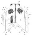
- FIG. 1is a partially cut-away, perspective view of two adjacent rigid, laser absorption panels joined by a rigid light strip and having optional base sections including casters;
- FIG. 2Ais a back view of one rigid, laser absorption panel showing the two pairs of hinge pins
- FIG. 2Bis a top sectional view of the laser absorption panel of FIG. 2A taken along section BB;
- FIG. 2Cis a top sectional view of the laser absorption panel of FIG. 2A taken along section CC;
- FIG. 3Ais a top view of a straight hinge pin of FIG. 2A;
- FIG. 3Bis a side view of a straight hinge pin of FIG. 2A;
- FIG. 4Ais a top view of an angled hinge pin of FIG. 2 A.
- FIG. 4Bis a side view of an angled hinge pin of FIG. 2A;
- FIG. 5Ais a top view of one rigid light strip with laterally extending hinge brackets to correspond to the pairs of hinge pins on adjacent laser absorption panels;
- FIG. 5Bis a front view of one rigid light strip with laterally extending hinge brackets
- FIG. 6Ais a top view of one laterally extending hinge bracket
- FIG. 6Bis a side sectional view of the laterally extending hinge bracket of FIG. 6A, taken along section BB;
- FIG. 6Cis a front sectional view of the laterally extending hinge bracket of FIG. 6A, taken along section CC;
- FIG. 7is a partial perspective view of the back side of one laser absorption panel with a rigid light strip hingably attached thereto.
- each laser absorption panel 12includes a frame 14 having a substantially rigid laser beam absorption panel 16 affixed thereto to form a front face of each panel 12 .
- Each frame 14may have an optional base section 18 upon which the laser containment barrier stands. Such a base section would allow a single panel to be self-standing.
- Base section 18may further include caster or rollers 20 , which would facilitate the movement and positioning of a laser beam absorption panel by itself or the positioning and movement of a laser containment barrier system made up of more than one hingably attached laser beam absorption panels.
- the substantially rigid, high power laser beam absorption sheet 16which is affixed to the frame 14 of each panel 12 is preferably a metallic sheet material and, in one preferred embodiment, is made out of aluminum, due to weight considerations.
- the metallic laser beam absorption panelmay further be textured and/or coated with a substantially black coating in order to aid in the diffusion and/or absorption of high power laser radiation.
- Each laser beam absorption sheet 16is attached to its frame 14 using a plurality of any type of suitable fasteners 22 , such as screws, rivets or the like.
- the laser beam absorption sheet 16may also be chemically bonded to the frame 14 or even welded thereto.
- the substantially rigid laser beam absorption sheets 16are EVER-GUARD sheets, which are sold by the Kentek Corporation of Pittsfield, N.H.
- EVER-GUARD sheetsare specially designed, textured aluminum barriers which feature an absorbing, substantially black matte finish.
- the EVER-GUARD sheetshave a front face, which includes a plurality of convex dimples. The front side of the EVER-GUARD sheet material is oriented toward a source of laser radiation. Thus, an unfocused, direct laser beam will be blocked by an EVER-GUARD sheet for extended time periods with minimal effects to the laser containment barrier.
- adjacent panels 12are hingably attached to each other using a novel arrangement of hinge pins and brackets, which are included on the back side of panels 12 and on the front side of rigid light strips 30 , respectively. While the following description will refer to an embodiment including two adjacent panels 12 and one intermediate, connecting light strip 30 , any number of partitions may be hingably attached to each other in a like manner in order to create portable, self-supporting laser containment barriers of differing sizes and configurations.
- the use of the combination of hinge pins 46 and 48 affixed to each panel 12 and corresponding hinge brackets 32 attached to an intermediate, rigid light strip 30will allow adjacent panels 12 to be hingably positioned with respect to each other. Accordingly, a multi-partition barrier system will be able to be self-standing and configured and oriented to provide a simple or elaborate laser containment system.
- each laser beam absorption panel 12includes a peripheral frame 14 to which is mounted a sheet 16 of a rigid, laser beam absorption material, such as an Ever-Guard sheet.
- the laser beam absorption sheet 16is mounted to a front side of each panel and extends to the peripheral edges of the frame 14 .
- the front side or face of each panel 12is substantially flat, with the exception of a texture, which is preferably a convex texture, which may be provided on the front face of each sheet of laser beam absorption material affixed thereto.
- each of the hinge pinsis aligned along a vertical axis V of each laser beam absorption panel.
- Vvertical axis
- the axis of rotation about the hinge pinsallows adjacent panels to be rotated in a book-like fashion to vary an angle intermediate two adjacent panels. Having angles between adjacent panels allows a barrier made from a combination of a plurality of hingably attached panels to be self-standing.
- a first hinge pin 46 of each hinge pin pairis simply a straight pin extending upwardly from a bottom member 54 of the peripheral frame 14 .
- each hinge pinpreferably includes a chamfered top end 64 .
- a second hinge pin 48 of each pin pairis provided as an “l-shaped”, angled hinge pin, which extends laterally from one of two panel frame side members 56 , proximate the top edge of the panel 12 , and then bends upwardly at and angle 9 , which is preferably a 90 degree angle so that an active hinge pin portion 58 is upwardly extending and is aligned with the first hinge pin of each hinge pin pair.
- the hinge pinsare secured to the frame side and bottom members, 56 and 54 , respectively, using techniques well known to those skilled in the art of metal manufacturing, such as welding or other mechanical fastening means. More detailed views of the hinge pins 46 and 48 are shown in FIGS. 3A, 3 B, 4 A and 4 B.
- one or more active hinge pin portions 58is provided with a locking hole 60 , through which a locking device, such as locking pin 62 , may be inserted to lock a bracket 32 onto the hinge pin 48 .
- FIGS. 5A and 5Bshow top and front views, respectively, of a rigid light strip 30 , which hingably attaches adjacent laser beam absorption panels 12 using adjacent hinge pin pairs of the adjacent panel sections 12 .
- Each light strip 30is made from a rigid laser beam absorption sheet and, in the preferred embodiment is made from the same Ever-Guard sheet material that is used as the laser beam absorption sheet 16 on each laser beam absorption panel 12 .
- Each light strip 30has a front face 34 to which two pairs of spaced and aligned, laterally extending brackets 32 are affixed using fasteners 33 . However, alternative means of fixing the brackets 32 to the light strip 30 , such as welding or chemical bonding are considered equivalent.
- Each laterally extending bracket 32has a hole 36 disposed therethrough, which corresponds to one of the vertically aligned hinge pins attached to adjacent laser beam absorption panels.
- each light stripmay be the convex textured side of the Ever-Guard material to diffuse any errant laser radiation directed upon the light strip when it is used to hingably attach adjacent laser beam absorption panels 12 .
- the light strip 30includes at least one angled wing section 38 , which is angled at an angle ⁇ towards the laterally extending hinge brackets 32 .
- the angled wing section(s) 38further assist in containing any errant radiation directed intermediate adjacent panels.
- Each laterally extending light strip hinge bracket 32has a first section 70 , which, when attached to a light strip, is parallel to the front face 34 of the light strip 30 to which it is attached.
- the first section 70may have one or more holes 72 disposed therethrough, which, when combined with corresponding holes passing through the light strip 30 to which it is attached and suitable fasteners 33 (FIG. 5B) mechanically attach the bracket 32 to the light strip 30 .
- Each bracketfurther includes a laterally extending section 74 , which includes a hinge pin hole 76 through which a corresponding panel hinge pin is passed to create the hinged joint between adjacent panels.
- the hinge pin hole 76includes an insert 78 , such as a plastic, Teflon or other friction reducing insert to facilitate the rotation of the bracket 32 about a corresponding hinge pin.
- the insert 38is replaceable and is replaced if it becomes excessively worn.
- FIG. 7shows a portion of the back side of one laser absorption panel 12 , to which a light strip 30 is attached using bracket 32 .
- bracket 32through which hole 76 passes, is inserted onto the upwardly extending, active hinge pin portion 58 of hinge pin 48 .
- a light strip 30having a total of four hinge brackets 32 is used to hingably attach adjacent laser absorption panels 12 using the two pairs of hinge pins 50 and 52 (FIG. 2A) provided on the adjacent panels 12 .
- Locking pin 62may be inserted through locking pin hole 30 provided in the hinge pin 48 to lock the light strip 30 onto the hinge pin 48 while still allowing the panel 12 and light strip 30 to rotate with respect to each other around vertical axis V.
- the beam absorption panels 14have a substantial range of angular motion relative to each other and to the light strip 30 .
- the panelsare movable to confront each other in a most closed position wherein their relative angular position about their hinge pin pivot axes may be relatively small, almost meeting as limited by the interference of the elements, e.g., 32 and 56 .
- the panelsmay be opened relative about their respective hinge pin pivot axes to each other to be co-planar (180°), until the other, most open extreme is reached, as illustrated by FIG. 7 .
- the most open positionis limited by the width of the light strip 30 , which strikes the panel element 42 .
- the relative motion of the absorption panelsis considerably greater and lesser than a co-planar disposition, and permits further contiguous connection to additional light strips and associated laser absorption panels.
- the panels 14sufficiently overlap the light strip 30 so as to present contiguously disposed laser absorption surfaces when viewed from the front of the laser absorption panels, which prevents the escape of laser beam containment.
Landscapes
- Engineering & Computer Science (AREA)
- General Engineering & Computer Science (AREA)
- Health & Medical Sciences (AREA)
- Life Sciences & Earth Sciences (AREA)
- Surgery (AREA)
- High Energy & Nuclear Physics (AREA)
- Physics & Mathematics (AREA)
- Heart & Thoracic Surgery (AREA)
- Pathology (AREA)
- Oral & Maxillofacial Surgery (AREA)
- Nuclear Medicine, Radiotherapy & Molecular Imaging (AREA)
- Biomedical Technology (AREA)
- Mechanical Engineering (AREA)
- Medical Informatics (AREA)
- Molecular Biology (AREA)
- Animal Behavior & Ethology (AREA)
- General Health & Medical Sciences (AREA)
- Public Health (AREA)
- Veterinary Medicine (AREA)
- Road Signs Or Road Markings (AREA)
Abstract
Description
Claims (12)
Priority Applications (1)
| Application Number | Priority Date | Filing Date | Title |
|---|---|---|---|
| US09/940,559US6571852B2 (en) | 2001-08-28 | 2001-08-28 | Colapsable, self-supporting, rigid laser containment barrier |
Applications Claiming Priority (1)
| Application Number | Priority Date | Filing Date | Title |
|---|---|---|---|
| US09/940,559US6571852B2 (en) | 2001-08-28 | 2001-08-28 | Colapsable, self-supporting, rigid laser containment barrier |
Publications (2)
| Publication Number | Publication Date |
|---|---|
| US20030051825A1 US20030051825A1 (en) | 2003-03-20 |
| US6571852B2true US6571852B2 (en) | 2003-06-03 |
Family
ID=25475048
Family Applications (1)
| Application Number | Title | Priority Date | Filing Date |
|---|---|---|---|
| US09/940,559Expired - Fee RelatedUS6571852B2 (en) | 2001-08-28 | 2001-08-28 | Colapsable, self-supporting, rigid laser containment barrier |
Country Status (1)
| Country | Link |
|---|---|
| US (1) | US6571852B2 (en) |
Cited By (6)
| Publication number | Priority date | Publication date | Assignee | Title |
|---|---|---|---|---|
| US20070258502A1 (en)* | 2006-05-02 | 2007-11-08 | Michael Harrison | Flexible laser safety curtain |
| US20070277940A1 (en)* | 2006-01-03 | 2007-12-06 | Chin-Fu Chen | Blind Slat Having Sealed Openings and Mimic Wooden Traces |
| US20080086964A1 (en)* | 2006-10-12 | 2008-04-17 | Mooreco Lp | Portable wall-partition |
| US20080173830A1 (en)* | 2006-10-05 | 2008-07-24 | Trumpf Laser- Und Systemtechnik Gmbh | Workroom partition |
| US20100084586A1 (en)* | 2008-07-15 | 2010-04-08 | Horia Mihail Teodorescu | Reconfigurable radiation shield |
| US8683928B2 (en) | 2012-01-23 | 2014-04-01 | Honeywell International Inc. | Laser barrier system for optical tables |
Families Citing this family (6)
| Publication number | Priority date | Publication date | Assignee | Title |
|---|---|---|---|---|
| DE102010042564B3 (en)* | 2010-10-18 | 2012-03-22 | Trumpf Laser- Und Systemtechnik Gmbh | Laser protection cabin and laser processing system with it |
| DE202017100227U1 (en) | 2017-01-17 | 2017-02-16 | JUTEC Hitzeschutz und Isoliertechnik GmbH | Laser protection device for shielding at least one laser light source with flat, flexible wall elements |
| DE102018210869B4 (en)* | 2018-07-02 | 2020-03-05 | Laservision Gmbh & Co. Kg | Swiveling corner element for a radiation protection wall and radiation protection wall |
| US11142903B1 (en)* | 2020-06-15 | 2021-10-12 | Nettalon Security Systems, Inc. | Protective enclosure for interior and exterior spaces |
| DE102020132983B3 (en)* | 2020-08-27 | 2022-02-10 | Alotec Dresden Gmbh | Mobile laser protection wall |
| CN112113129B (en)* | 2020-08-27 | 2024-05-31 | 欣润新材料科技(江苏)有限公司 | Special eye protection barrier for electric welding area for filtering harmful light |
Citations (17)
| Publication number | Priority date | Publication date | Assignee | Title |
|---|---|---|---|---|
| US543906A (en)* | 1895-08-06 | Algenon s | ||
| US696199A (en)* | 1901-11-04 | 1902-03-25 | August Volkmann | Sidewalk covering or protector. |
| US1300722A (en)* | 1918-08-06 | 1919-04-15 | Askowetz Brothers | Hospital-screen. |
| US2317708A (en)* | 1941-02-10 | 1943-04-27 | Doris Zareko | Assembled picture frame or the like |
| US2380206A (en)* | 1942-06-24 | 1945-07-10 | Wiser Guy Brown | Bookbinding |
| US2406729A (en)* | 1944-02-28 | 1946-08-27 | Avis K White | Handy two-part folding screen |
| US3092870A (en)* | 1960-07-15 | 1963-06-11 | Austin R Baer | Hinge |
| US3921225A (en)* | 1972-08-09 | 1975-11-25 | Stanley Works | Long life hinge |
| US4608495A (en)* | 1983-11-21 | 1986-08-26 | Jacobson Earl Bruce | Collapsible radiation attenuation system |
| US4838525A (en) | 1987-11-27 | 1989-06-13 | Snow Claud R | Portable barrier means |
| US5058863A (en) | 1988-09-15 | 1991-10-22 | Maffet Harold C | Panel apparatus and elements for securing a plurality of panels together |
| US5199478A (en)* | 1991-10-12 | 1993-04-06 | Nichimen Corporation | Air-tightening devices in folding doors and windows |
| US5544436A (en)* | 1994-01-25 | 1996-08-13 | Lefkowitz; Jay | Multi-photo display apparatus |
| US5584330A (en) | 1995-10-30 | 1996-12-17 | Muller; Peter J. | Flexible partition |
| US5992417A (en) | 1998-03-02 | 1999-11-30 | Kentek Corporation | Portable, self-supporting, rigid laser containment barrier |
| US6095226A (en)* | 1999-01-11 | 2000-08-01 | Chen; Hong-Jen | Structure multipurpose partition |
| US6123321A (en) | 1998-02-12 | 2000-09-26 | Miller; David | Modular resilient child or pet safety fence system |
- 2001
- 2001-08-28USUS09/940,559patent/US6571852B2/ennot_activeExpired - Fee Related
Patent Citations (17)
| Publication number | Priority date | Publication date | Assignee | Title |
|---|---|---|---|---|
| US543906A (en)* | 1895-08-06 | Algenon s | ||
| US696199A (en)* | 1901-11-04 | 1902-03-25 | August Volkmann | Sidewalk covering or protector. |
| US1300722A (en)* | 1918-08-06 | 1919-04-15 | Askowetz Brothers | Hospital-screen. |
| US2317708A (en)* | 1941-02-10 | 1943-04-27 | Doris Zareko | Assembled picture frame or the like |
| US2380206A (en)* | 1942-06-24 | 1945-07-10 | Wiser Guy Brown | Bookbinding |
| US2406729A (en)* | 1944-02-28 | 1946-08-27 | Avis K White | Handy two-part folding screen |
| US3092870A (en)* | 1960-07-15 | 1963-06-11 | Austin R Baer | Hinge |
| US3921225A (en)* | 1972-08-09 | 1975-11-25 | Stanley Works | Long life hinge |
| US4608495A (en)* | 1983-11-21 | 1986-08-26 | Jacobson Earl Bruce | Collapsible radiation attenuation system |
| US4838525A (en) | 1987-11-27 | 1989-06-13 | Snow Claud R | Portable barrier means |
| US5058863A (en) | 1988-09-15 | 1991-10-22 | Maffet Harold C | Panel apparatus and elements for securing a plurality of panels together |
| US5199478A (en)* | 1991-10-12 | 1993-04-06 | Nichimen Corporation | Air-tightening devices in folding doors and windows |
| US5544436A (en)* | 1994-01-25 | 1996-08-13 | Lefkowitz; Jay | Multi-photo display apparatus |
| US5584330A (en) | 1995-10-30 | 1996-12-17 | Muller; Peter J. | Flexible partition |
| US6123321A (en) | 1998-02-12 | 2000-09-26 | Miller; David | Modular resilient child or pet safety fence system |
| US5992417A (en) | 1998-03-02 | 1999-11-30 | Kentek Corporation | Portable, self-supporting, rigid laser containment barrier |
| US6095226A (en)* | 1999-01-11 | 2000-08-01 | Chen; Hong-Jen | Structure multipurpose partition |
Cited By (12)
| Publication number | Priority date | Publication date | Assignee | Title |
|---|---|---|---|---|
| US20070277940A1 (en)* | 2006-01-03 | 2007-12-06 | Chin-Fu Chen | Blind Slat Having Sealed Openings and Mimic Wooden Traces |
| US20070258502A1 (en)* | 2006-05-02 | 2007-11-08 | Michael Harrison | Flexible laser safety curtain |
| WO2007130314A3 (en)* | 2006-05-02 | 2009-04-02 | Telesis Tech Inc | Flexible laser safety curtain |
| US7626763B2 (en)* | 2006-05-02 | 2009-12-01 | Telesis Technologies, Inc. | Flexible laser safety curtain |
| US20080173830A1 (en)* | 2006-10-05 | 2008-07-24 | Trumpf Laser- Und Systemtechnik Gmbh | Workroom partition |
| US7800087B2 (en)* | 2006-10-05 | 2010-09-21 | Trumpf Laser- Und Systemtechnik Gmbh | Workroom partition |
| US20080086964A1 (en)* | 2006-10-12 | 2008-04-17 | Mooreco Lp | Portable wall-partition |
| US7584776B2 (en)* | 2006-10-12 | 2009-09-08 | Mooreco, Inc. | Portable wall-partition |
| US20090255638A1 (en)* | 2006-10-12 | 2009-10-15 | Mooreco., Inc. | Portable wall-partition |
| US20100084586A1 (en)* | 2008-07-15 | 2010-04-08 | Horia Mihail Teodorescu | Reconfigurable radiation shield |
| US8143607B2 (en)* | 2008-07-15 | 2012-03-27 | Horia Mihail Teodorescu | Reconfigurable radiation shield |
| US8683928B2 (en) | 2012-01-23 | 2014-04-01 | Honeywell International Inc. | Laser barrier system for optical tables |
Also Published As
| Publication number | Publication date |
|---|---|
| US20030051825A1 (en) | 2003-03-20 |
Similar Documents
| Publication | Publication Date | Title |
|---|---|---|
| US6571852B2 (en) | Colapsable, self-supporting, rigid laser containment barrier | |
| US5992417A (en) | Portable, self-supporting, rigid laser containment barrier | |
| AU2005232592B2 (en) | Radiation barrier | |
| RU2756817C2 (en) | Mobile radiation protection screen | |
| US5006718A (en) | X-ray shield for X-ray examination table | |
| JP6942362B2 (en) | Radiation shielding device and its applications | |
| US5673431A (en) | Face mask safety shield | |
| US6325538B1 (en) | Radiation field isolator apparatus | |
| RU2166600C1 (en) | Device for door guiding system with flexible blind | |
| US5306065A (en) | Supplemental visor assembly | |
| ES2476090T3 (en) | High speed roller door with roller blade | |
| SI20082B (en) | Garage door construction | |
| PT2144565E (en) | Sterile cover for a screen made of radioprotective material | |
| TW200803088A (en) | Flexible laser safety curtain | |
| DE102017113995A1 (en) | Laser protection device for shielding at least one laser light source with flat, flexible wall elements | |
| US4158779A (en) | X-ray shield | |
| CA1210531A (en) | X-ray filter for chest x-rays | |
| US20220262533A1 (en) | Radiation shield for operating table | |
| CN207892411U (en) | A kind of hardware system and fire window | |
| CN110141265A (en) | Mobile medical radiation protection device in lying position | |
| KR20210002413U (en) | Barricade with foldable identification panel | |
| CN210541604U (en) | Medical ray protective cover | |
| US3433957A (en) | Prefabricated radiation safe window adjustable for mounting in biological shields of different thicknesses | |
| EP0372206B1 (en) | Glass door construction with a hinge for glass partition walls in gymnasiums | |
| NL1001051C2 (en) | Shielding wall. |
Legal Events
| Date | Code | Title | Description |
|---|---|---|---|
| AS | Assignment | Owner name:KENTEK CORPORATION, NEW HAMPSHIRE Free format text:ASSIGNMENT OF ASSIGNORS INTEREST;ASSIGNOR:TOEPEL, MICHAEL P.;REEL/FRAME:012126/0953 Effective date:20010828 | |
| FEPP | Fee payment procedure | Free format text:PETITION RELATED TO MAINTENANCE FEES FILED (ORIGINAL EVENT CODE: PMFP); ENTITY STATUS OF PATENT OWNER: LARGE ENTITY | |
| REMI | Maintenance fee reminder mailed | ||
| REIN | Reinstatement after maintenance fee payment confirmed | ||
| FP | Lapsed due to failure to pay maintenance fee | Effective date:20070603 | |
| FPAY | Fee payment | Year of fee payment:4 | |
| SULP | Surcharge for late payment | ||
| FEPP | Fee payment procedure | Free format text:PETITION RELATED TO MAINTENANCE FEES GRANTED (ORIGINAL EVENT CODE: PMFG); ENTITY STATUS OF PATENT OWNER: LARGE ENTITY | |
| PRDP | Patent reinstated due to the acceptance of a late maintenance fee | Effective date:20080311 | |
| FEPP | Fee payment procedure | Free format text:PETITION RELATED TO MAINTENANCE FEES FILED (ORIGINAL EVENT CODE: PMFP); ENTITY STATUS OF PATENT OWNER: LARGE ENTITY | |
| FEPP | Fee payment procedure | Free format text:PETITION RELATED TO MAINTENANCE FEES GRANTED (ORIGINAL EVENT CODE: PMFG); ENTITY STATUS OF PATENT OWNER: LARGE ENTITY | |
| REMI | Maintenance fee reminder mailed | ||
| LAPS | Lapse for failure to pay maintenance fees | ||
| REIN | Reinstatement after maintenance fee payment confirmed | ||
| FP | Lapsed due to failure to pay maintenance fee | Effective date:20110603 | |
| FPAY | Fee payment | Year of fee payment:8 | |
| PRDP | Patent reinstated due to the acceptance of a late maintenance fee | Effective date:20111220 | |
| REMI | Maintenance fee reminder mailed | ||
| LAPS | Lapse for failure to pay maintenance fees | ||
| STCH | Information on status: patent discontinuation | Free format text:PATENT EXPIRED DUE TO NONPAYMENT OF MAINTENANCE FEES UNDER 37 CFR 1.362 | |
| FP | Lapsed due to failure to pay maintenance fee | Effective date:20150603 |