US6571639B1 - Fiber optic system - Google Patents
Fiber optic systemDownload PDFInfo
- Publication number
- US6571639B1 US6571639B1US09/259,972US25997299AUS6571639B1US 6571639 B1US6571639 B1US 6571639B1US 25997299 AUS25997299 AUS 25997299AUS 6571639 B1US6571639 B1US 6571639B1
- Authority
- US
- United States
- Prior art keywords
- fiber optic
- fiber
- optic system
- strain gage
- stressed
- Prior art date
- Legal status (The legal status is an assumption and is not a legal conclusion. Google has not performed a legal analysis and makes no representation as to the accuracy of the status listed.)
- Expired - Lifetime
Links
- 239000000835fiberSubstances0.000titleclaimsabstractdescription106
- 238000000034methodMethods0.000claimsabstractdescription11
- 238000004458analytical methodMethods0.000claimsabstractdescription7
- 238000012545processingMethods0.000claimsdescription15
- 238000000576coating methodMethods0.000claimsdescription13
- 239000013307optical fiberSubstances0.000claimsdescription12
- 239000011248coating agentSubstances0.000claimsdescription11
- 230000008859changeEffects0.000claimsdescription10
- XUIMIQQOPSSXEZ-UHFFFAOYSA-NSiliconChemical compound[Si]XUIMIQQOPSSXEZ-UHFFFAOYSA-N0.000claimsdescription8
- 229910052710siliconInorganic materials0.000claimsdescription8
- 239000010703siliconSubstances0.000claimsdescription8
- 239000011347resinSubstances0.000description11
- 229920005989resinPolymers0.000description11
- 238000004519manufacturing processMethods0.000description9
- 239000002131composite materialSubstances0.000description8
- 238000012360testing methodMethods0.000description7
- 229910052451lead zirconate titanateInorganic materials0.000description6
- 229910052751metalInorganic materials0.000description6
- 239000002184metalSubstances0.000description6
- 230000008569processEffects0.000description5
- 239000000919ceramicSubstances0.000description4
- 239000011888foilSubstances0.000description4
- 239000010410layerSubstances0.000description4
- 239000004593EpoxySubstances0.000description3
- 239000000853adhesiveSubstances0.000description3
- 230000001070adhesive effectEffects0.000description3
- 239000000463materialSubstances0.000description3
- 239000011159matrix materialSubstances0.000description3
- 238000012544monitoring processMethods0.000description3
- 229920001721polyimidePolymers0.000description3
- 229920001187thermosetting polymerPolymers0.000description3
- 239000004634thermosetting polymerSubstances0.000description3
- 238000013459approachMethods0.000description2
- 238000012512characterization methodMethods0.000description2
- 239000011247coating layerSubstances0.000description2
- 238000007596consolidation processMethods0.000description2
- 230000003247decreasing effectEffects0.000description2
- 230000005284excitationEffects0.000description2
- 238000001879gelationMethods0.000description2
- 239000012212insulatorSubstances0.000description2
- 238000005259measurementMethods0.000description2
- 230000035945sensitivityEffects0.000description2
- 125000006850spacer groupChemical group0.000description2
- 239000004642PolyimideSubstances0.000description1
- RTAQQCXQSZGOHL-UHFFFAOYSA-NTitaniumChemical compound[Ti]RTAQQCXQSZGOHL-UHFFFAOYSA-N0.000description1
- 239000004020conductorSubstances0.000description1
- 230000008878couplingEffects0.000description1
- 238000010168coupling processMethods0.000description1
- 238000005859coupling reactionMethods0.000description1
- 238000011161developmentMethods0.000description1
- 238000006073displacement reactionMethods0.000description1
- 230000008030eliminationEffects0.000description1
- 238000003379elimination reactionMethods0.000description1
- 239000003365glass fiberSubstances0.000description1
- 238000007731hot pressingMethods0.000description1
- 238000011065in-situ storageMethods0.000description1
- HFGPZNIAWCZYJU-UHFFFAOYSA-Nlead zirconate titanateChemical compound[O-2].[O-2].[O-2].[O-2].[O-2].[Ti+4].[Zr+4].[Pb+2]HFGPZNIAWCZYJU-UHFFFAOYSA-N0.000description1
- 238000012986modificationMethods0.000description1
- 230000004048modificationEffects0.000description1
- 230000003287optical effectEffects0.000description1
- 230000010363phase shiftEffects0.000description1
- 229920013657polymer matrix compositePolymers0.000description1
- 239000011160polymer matrix compositeSubstances0.000description1
- 239000002952polymeric resinSubstances0.000description1
- 238000003825pressingMethods0.000description1
- 239000012783reinforcing fiberSubstances0.000description1
- 238000011160researchMethods0.000description1
- 238000000926separation methodMethods0.000description1
- 229920003002synthetic resinPolymers0.000description1
- 239000010936titaniumSubstances0.000description1
- 229910052719titaniumInorganic materials0.000description1
Images


Classifications
- G—PHYSICS
- G01—MEASURING; TESTING
- G01L—MEASURING FORCE, STRESS, TORQUE, WORK, MECHANICAL POWER, MECHANICAL EFFICIENCY, OR FLUID PRESSURE
- G01L1/00—Measuring force or stress, in general
- G01L1/24—Measuring force or stress, in general by measuring variations of optical properties of material when it is stressed, e.g. by photoelastic stress analysis using infrared, visible light, ultraviolet
- G01L1/242—Measuring force or stress, in general by measuring variations of optical properties of material when it is stressed, e.g. by photoelastic stress analysis using infrared, visible light, ultraviolet the material being an optical fibre
Definitions
- the present inventionrelates to instrumentation used to conduct dynamic mechanical analysis on a sample during and after a cure cycle.
- itrelates to a fiber optic system capable of performing dynamic mechanical analysis.
- thermosetting polymersit is often difficult to determine the extent of cure of thermosetting polymers during the manufacturing of polymer matrix composites.
- a compositeis cured using a manufacturer-recommended time-temperature schedule instead of directly monitoring the resin properties as the sample cures. Once the schedule is complete, the resulting part is inspected and tested to insure that the mechanical properties are acceptable.
- thermosetting polymer matrix compositeis fully cured prior to use.
- approachesinclude measuring the refractive index of the resin; measuring the dielectric properties of the resin; or monitoring the acoustic attenuation of the material. More recently, investigators (Russell G. May et al., “ In-Situ Fiber Optic Sensor for Composite Cure Monitoring Through Characterization of Resin Viscoelasticity ,” Proc. Of SPIE, Vol. 2948, pp 24-34, December 1996; and Russell G. May et al., “ Multifunctional Fiber Optic Sensor for Manufacturing of Thermoset Matrix Composite Materials ,” Proc. Of SPIE, Vol.
- the piezoelectric actuators typically used for constructing the sensor assemblyare brittle or fracture easily during typical composite manufacturing processes, such as hot pressing.
- absolute measurements of the complex modulus of the resindepends on the distance separating the vibrating actuator from any adjacent unmoving boundaries. Since this distance cannot generally be fixed in composite manufacturing, the complex modulus cannot be measured in an absolute sense. Only relative changes in modulus can be determined.
- the determination of the vibration amplitude by the use of fiber optic strain gagesis sensitive to optical losses that may result in the optical fiber or the optical fiber connector.
- An object of the present inventionis to provide a fiber optic system that uses a robust piezoelectric actuator which is capable of withstanding the application of pressure.
- Another object of the present inventionis to establish fixed boundary conditions for the sensor assembly.
- Another object of the present inventionis to render the determination of the vibration amplitude insensitive to fiber optic losses.
- a fiber optic systemwhich comprises a laminated, pre-stressed, piezoelectric actuator; and a fiber optic strain gage having an input/output fiber.
- the fiber optic strain gageis attached to a surface of the laminated, pre-stressed, piezoelectric actuator.
- the fiber optic systemcomprises a high voltage amplifier and frequency generator attached to fine gauge wires that are attached to an electrode pair on the laminated, pre-stressed, piezoelectric actuator.
- a signal processing unitis positioned in an operable relationship to the input/output optical fiber and the fine gage wires.
- a micromachined silicon housingsurrounds the actuator and the fiber optic strain gage.
- the fiber optic system of the present inventionis useful for performing dynamic mechanical analysis on a sample.
- the fiber optic systemis provided and a sample is exposed to the system.
- a stressis applied to the sample through the actuator and a change in the strain amplitude signal of the sample is measured using the signal processing unit.
- FIG. 1is a perspective view of the fiber optic system of the present invention.
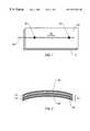
- FIG. 2is a side view of a laminated, pre-stressed, piezoelectric actuator.
- FIG. 3is a side view of the fiber optic system having a micromachined silicon housing surrounding the fiber optic strain gage and the piezoelectric actuator.
- FIG. 4is a perspective view of the fiber optic system wherein the piezoelectric actuator has an electrode pair and fine gauge wires attached thereto.
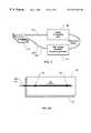
- FIG. 5depicts an arrangement of the fiber optic system including a high voltage amplifier and frequency generator and a signal processing unit.
- FIG. 6Ais a perspective view of the fiber optic system where a metallic coating is disposed on a portion of the input/output fiber and the fiber optic strain gage.
- FIG. 6Bshows an arrangement of the fiber optic system when a metallic coating is disposed on a portion of the input/output fiber and the fiber optic strain gage.
- FIG. 1depicts the simplest embodiment of the fiber optic system.
- the systemcomprises a laminated, pre-stressed, piezoelectric actuator 10 and a fiber optic strain gage 20 attached to a surface 30 of the laminated, pre-stressed, piezoelectric actuator 10 .
- the fiber optic strain gagemay be attached to any surface of the actuator but preferably, it is attached to a convex side of the actuator.
- the fiber optic strain gageis attached to the actuator with an adhesive 25 and, in particular, an epoxy is used.
- the fiber optic strain gage 20has an input/output fiber 40 for directing and reflecting light through the device.
- the novelty of the inventionrests in the laminated, pre-stressed, piezoelectric actuator used in the invention.
- This actuatorshown in FIG. 2, differs from that used previously.
- the piezoelectric actuator of the present inventionis laminated and pre-stressed. It was discovered that the laminated structure allows the actuator to undergo the application of pressure without fracturing. As a result, it is now possible to collect data during the pressure application step during a prepreg fabrication process. This was not previously accomplished by May et al. In the work of May et al., the ceramic piezoelectric actuators fractured when pressure was applied to the prepreg lay-Up. Thus, the arrangement of May et al. was ineffective for applications involving prepreg material or reinforcing fibers that have been impregnated with a resin and must undergo the application of pressure during the fabrication process.
- the laminated, pre-stressed, piezoelectric actuators of the present inventionare constructed in a method similar to that disclosed in U.S. Pat. No. 5,632,841 to Helibaum et al., which is hereby incorporated by reference.
- the method of fabricationemploys a sheet of lead-zirconate-titanate (PZT) ceramic 50 which is sandwiched between a pre-stressed metal foil sheet 60 and a polyimide film 70 .
- PZTlead-zirconate-titanate
- a laminateis formed by laying-up the metal foil, a layer of polyimide film, the PZT, another layer of polyimide film and another layer of metal foil. It was discovered that this particular fabrication method allowed the actuator to have either a planar or 3-D shape which allows for the application of pressure to the device without damaging it.
- the fiber optic strain gage 20is depicted as a region of the optical fiber 40 and is any fiber optic strain gage known to those skilled in the art.
- the fiber optic strain gageis an extrinsic Fabry-Perot interferometer. These types of strain gages are well-known in the art and are disclosed in U.S. Pat. No. 5,301,001 to Murphy et al., the disclosure of which is hereby incorporated by reference.
- the fiber optic strain gagecomprises an optical fiber having a long period grating disposed therein.
- the fiber optic strain gagecomprises an optical fiber having a Bragg (or short period) grating disposed therein.
- FIG. 3depicts a further embodiment of the invention wherein the fiber optic strain gage 20 is attached to the piezoelectric actuator 10 with an adhesive 25 and the assembly is housed in a micromachined silicon housing 80 .
- the housing 80comprises a top plate 90 , a lower plate 100 and two identical sides or spacers 110 , 120 that clamp onto the piezoelectric actuator 10 to complete the assembly.
- the top plate 90 and the lower plate 100have a plurality of ports 130 that permit the resin to flow to the sensor.
- the spacers 110 , 120have clamps 140 that clamp onto the actuator 10 .
- FIG. 4depicts an electrode pair 150 located on the piezoelectric actuator 10 along with the fiber optic strain gage 20 which is attached by an adhesive 25 .
- the piezoelectric actuator 10has an electrode pair 150 (shown in a preferred location but may be located anywhere on the actuator).
- Fine gauge wires 160serve as positive and negative leads and are attached to each of the electrodes 150 . By fine it is meant that the gauge ranges from about 22 to about 30 gauge.
- FIG. 5depicts a further embodiment where a high voltage amplifier and frequency generator 170 are attached to the fine gauge wires 160 at an end opposite from that attached to the electrodes (not shown).
- the voltage amplifier and frequency generator 170causes the actuator 10 to move throughout the test.
- a signal processing unit 180positioned in an operable relationship to the input/output optical fiber 40 and the fine gauge wires 160 .
- the signal processing unit 180is comprised of a source/detector, digital signal processed (DSP)-based absolute strain measurement system, a lock-in amplifier, and a computer.
- DSPdigital signal processed
- FIG. 6Ashows an alternate embodiment of the invention where at least one metallic coating 190 is disposed on a portion of the input/output fiber 40 and the fiber optic strain gage 20 .
- the metallic coatingis a conductor and allows elimination of one or both throughputs by replacing one or both of the electrodes on the piezoelectric actuator.
- the metallic coating(s)may be applied to the fiber using several different configurations.
- the metallic coatingmay be prepared from the same material and applied to the fiber. In this configuration, an insulator or a physical boundary is placed at two separate places to form separate positive and negative contacts. It is also possible to have two separate conductive metal coatings disposed on the input/output fiber.
- the fiber optic strain gage 20comprises an optical fiber having a Bragg grating disposed therein.
- a high voltage amplifier and frequency generator 170are attached to the actuator 10 by fine gauge wires 160 that are attached to the metallic coated portion of the input/output fiber 190 .
- a signal processing unit 180is positioned in an operable relationship to the input/output fiber 40 and the fine gauge wires 160 .
- the device of this inventionpermits dynamic mechanical analysis to be performed on a sample either as it cures or after it has cured.
- samplesinclude but are not limited to polymeric resins or ceramic, titanium or polymeric matrix composites.
- a fiber optic systemcomprising a laminated, pre-stressed, piezoelectric actuator having an electrode pair and fine gauge wires attached to the electrodes is provided.
- a fiber optic strain gageis attached to a surface of the laminated, pre-stressed, piezoelectric actuator.
- a micromachined silicon housingsurrounds the actuator and the fiber optic strain gage.
- a high voltage amplifier and frequency generatorare attached to the fine gauge wires.
- An input/output fiberis attached to the fiber optic strain gage.
- a signal processing unit for measuring a strain amplitude signalis positioned in an operable relationship to the input/output fiber and the fine gauge wires.
- the sampleis exposed to the fiber optic system.
- exposedit is meant that the fiber optic system is either embedded or attached to the test sample.
- a stressis applied to the sample through the actuator.
- a change in the strain amplitude signal for the sampleis measured using the signal processing unit.
- the absolute shear modulus and loss tangentare derived from the strain amplitude signal and a change in the exposed sample is determined.
- a pre-stressed, laminated, piezoelectric actuatorwas constructed following the process described in U.S. Pat. No. 5,632,841 to Hellbaum et al.
- An extrinsic Fabry-Perot interferometer(EFPI) strain sensorwas attached to the upperside or pre-stressed side of the actuator using an epoxy.
- the sensitivity of the sensor outputswas tested by suspending the sensor in air in a small oven and recording the sensor outputs as the temperature was increased to 180° C. and then cooled to room temperature.
- a plot of the phase as a function of frequency, an average value of 0.03 degrees (phase) per degree Celsiuswas estimated for the temperature dependence. The change in the strain amplitude signal was also recorded during this test.
- the voltage output by the lock-in amplifierwas recorded, which is the root-mean-square (RMS) value of the sinusoidally varying signal output by the absolute fiber sensor system, which in turn monitors the fiber optic strain gage.
- RMSroot-mean-square
- the output signalAs the temperature increased from 21° C. to 180° C., the output signal also increased from 239 mV to 347mV.
- the strain amplitudedecreased from 347 mV to 248 mV.
- the temperature-induced change in signal amplitudewas found to be 0.4%° C. ⁇ 1 .
- the sensorwas embedded in the midplane of a twelve-ply ( 0 2 / 90 2 / 0 2 ) 5 Gr/Ep lay-up, together with a thermocouple to measure the temperature.
- the lay-upwas placed in a Carver brand hydraulically-operated press and pressure applied to allow for contact between the layers.
- the temperaturewas increased to 100° C. and the pressure was maintained for approximately 40 minutes.
- a nominal pressuresufficient to permit contact of upper and lower plates to the prepreg was applied, and the temperature was ramped to the final temperature of 180° C.
- the phase output of the lock-in amplifier at 0.5 Hzshowed a trend that appears to follow the increase in temperature.
- the strain amplitude signal at 0.5 Hzshowed a somewhat stronger correlation with the temperature changes.
- the factor (0.4%/° C). derived for the temperature-induced change in signalwas multiplied by the change in temperature, and then the result was multiplied by the uncorrected signal. This result, which yielded the variation due to temperature, was subtracted from the uncorrected signal to give the final temperature-corrected signal. It was observed that the trend indicated that the strain amplitude is relatively constant up to 100 minutes into the test, and decreased over the next fifty minutes.
- Example 2Another sensor was constructed in a similar manner to that of Example 1.
- a 32-ply glass fiber in thermoplastic-toughened epoxy prepreg cross-ply lay-upwas constructed with the sensor embedded in it and cured in a vacuum bag in an oven. The sensor survived the lay-up process, including pressing the sensor into the prepreg with a roller, followed by application of 15 psi consolidation pressure through a vacuum bag.
- a second sensor, employing a standard PZT (ceramic) actuator(similar to that of May et al.), did not survive the lay-up and consolidation process.
- the sensorswere put in the laminate midplane, surrounded by two plies with 0° orientation (that is, parallel to the optical fiber leads) on both sides.
- three thermocouplestop, bottom and midplane
- a dc conductivity sensorwere added for logging by the data acquisition system.
- the dc conductivity sensormeasured the ionic conductivity of the resin, which is proportional to the steady shear viscosity.
- a vacuum bagwas added, and vacuum was applied. The lay-up was then cured under vacuum in the oven.
- the cure cycle for the prepregused a 6 hour cycle, with a final soak at 176° C. and a couple of intermediate soaks at lower temperatures.
- the sensorcontinued to work throughout the cure cycle.
- the sensor strain amplitudeincreased at the beginning of the test, and leveled off at the first temperature soak (200° F.).
- the strain amplitudedropped by about 90% over a period of approximately 15 minutes, starting at a time coincident with a dramatic rise in viscosity, as measured by the conductivity sensor. This drop in strain amplitude was consistent with the increase in absolute shear modulus expected during gelation.
Landscapes
- Physics & Mathematics (AREA)
- General Physics & Mathematics (AREA)
- Length Measuring Devices By Optical Means (AREA)
Abstract
Description
Claims (18)
Priority Applications (1)
| Application Number | Priority Date | Filing Date | Title |
|---|---|---|---|
| US09/259,972US6571639B1 (en) | 1999-03-01 | 1999-03-01 | Fiber optic system |
Applications Claiming Priority (1)
| Application Number | Priority Date | Filing Date | Title |
|---|---|---|---|
| US09/259,972US6571639B1 (en) | 1999-03-01 | 1999-03-01 | Fiber optic system |
Publications (1)
| Publication Number | Publication Date |
|---|---|
| US6571639B1true US6571639B1 (en) | 2003-06-03 |
Family
ID=22987262
Family Applications (1)
| Application Number | Title | Priority Date | Filing Date |
|---|---|---|---|
| US09/259,972Expired - LifetimeUS6571639B1 (en) | 1999-03-01 | 1999-03-01 | Fiber optic system |
Country Status (1)
| Country | Link |
|---|---|
| US (1) | US6571639B1 (en) |
Cited By (36)
| Publication number | Priority date | Publication date | Assignee | Title |
|---|---|---|---|---|
| US20030219191A1 (en)* | 2002-04-04 | 2003-11-27 | Michael Kehlenbach | Actuator and sensor system for composite structures |
| US20040174542A1 (en)* | 2003-03-07 | 2004-09-09 | Boxboro Systems Llc | Optical measurement device and method |
| US20050254062A1 (en)* | 2003-11-06 | 2005-11-17 | Fortebio, Inc. | Fiber-optic assay apparatus based on phase-shift interferometry |
| US20060154320A1 (en)* | 2005-01-07 | 2006-07-13 | Fortebio, Inc. | Enzyme activity measurement using bio-layer interferometry |
| US20070156019A1 (en)* | 2005-12-30 | 2007-07-05 | Larkin David Q | Robotic surgery system including position sensors using fiber bragg gratings |
| US20070151943A1 (en)* | 2002-03-13 | 2007-07-05 | Samsung Electro-Mechanics Co., Ltd. | Fluxgate sensor integrated in printed circuit board and method for manufacturing the same |
| US20070265503A1 (en)* | 2006-03-22 | 2007-11-15 | Hansen Medical, Inc. | Fiber optic instrument sensing system |
| US20080141780A1 (en)* | 2006-12-01 | 2008-06-19 | Wavering Thomas A | Sensors, methods and systems for determining physical effects of a fluid |
| US20080144039A1 (en)* | 2003-11-06 | 2008-06-19 | Fortebio, Inc. | Fiber-Optic Assay Apparatus Based on Phase-Shift Interferometry |
| US20080218770A1 (en)* | 2007-02-02 | 2008-09-11 | Hansen Medical, Inc. | Robotic surgical instrument and methods using bragg fiber sensors |
| US20080285909A1 (en)* | 2007-04-20 | 2008-11-20 | Hansen Medical, Inc. | Optical fiber shape sensing systems |
| US20090059209A1 (en)* | 2007-09-05 | 2009-03-05 | An-Dien Nguyen | Lock-in demodulation technique for optical interrogation of a grating sensor |
| US20090137952A1 (en)* | 2007-08-14 | 2009-05-28 | Ramamurthy Bhaskar S | Robotic instrument systems and methods utilizing optical fiber sensor |
| US20090196543A1 (en)* | 2008-02-05 | 2009-08-06 | The Government Of The Us, As Represented By The Secretary Of The Navy | Fiber Optic Acceleration and Displacement Sensors |
| US20090324161A1 (en)* | 2008-06-30 | 2009-12-31 | Intuitive Surgical, Inc. | Fiber optic shape sensor |
| US20100093106A1 (en)* | 2006-09-14 | 2010-04-15 | Fortebio, Inc. | Amine-Reactive Biosensor |
| US20130091956A1 (en)* | 2011-10-13 | 2013-04-18 | Baker Hughes Incorporated | Sensing assembly |
| US8647588B2 (en) | 2005-06-13 | 2014-02-11 | Pall Corporation | Tip tray assembly for optical sensors |
| US8780339B2 (en) | 2009-07-15 | 2014-07-15 | Koninklijke Philips N.V. | Fiber shape sensing systems and methods |
| US8989528B2 (en) | 2006-02-22 | 2015-03-24 | Hansen Medical, Inc. | Optical fiber grating sensors and methods of manufacture |
| US9060678B2 (en) | 2006-06-13 | 2015-06-23 | Intuitive Surgical Operations, Inc. | Minimally invasive surgical system |
| US9358076B2 (en) | 2011-01-20 | 2016-06-07 | Hansen Medical, Inc. | System and method for endoluminal and translumenal therapy |
| US9387048B2 (en) | 2011-10-14 | 2016-07-12 | Intuitive Surgical Operations, Inc. | Catheter sensor systems |
| US9452276B2 (en) | 2011-10-14 | 2016-09-27 | Intuitive Surgical Operations, Inc. | Catheter with removable vision probe |
| US20160282507A1 (en)* | 2014-01-20 | 2016-09-29 | Halliburton Energy Services, Inc. | Hydraulic fracture geometry monitoring with downhole distributed strain measurements |
| US9757149B2 (en) | 2006-06-13 | 2017-09-12 | Intuitive Surgical Operations, Inc. | Surgical system entry guide |
| US9891161B2 (en) | 2014-03-14 | 2018-02-13 | Rosemount Inc. | Corrosion rate measurement |
| US9962066B2 (en) | 2005-12-30 | 2018-05-08 | Intuitive Surgical Operations, Inc. | Methods and apparatus to shape flexible entry guides for minimally invasive surgery |
| US10130427B2 (en) | 2010-09-17 | 2018-11-20 | Auris Health, Inc. | Systems and methods for positioning an elongate member inside a body |
| US10161924B2 (en) | 2014-03-24 | 2018-12-25 | National Technology & Engineering Solutions Of Sandia, Llc | Sensor system that uses embedded optical fibers |
| US10190968B2 (en) | 2015-06-26 | 2019-01-29 | Rosemount Inc. | Corrosion rate measurement with multivariable sensor |
| US10238837B2 (en) | 2011-10-14 | 2019-03-26 | Intuitive Surgical Operations, Inc. | Catheters with control modes for interchangeable probes |
| WO2019179079A1 (en)* | 2018-03-23 | 2019-09-26 | 京东方科技集团股份有限公司 | Pressure visualization device and manufacturing method therefor, and detection apparatus |
| US10667720B2 (en) | 2011-07-29 | 2020-06-02 | Auris Health, Inc. | Apparatus and methods for fiber integration and registration |
| US10682070B2 (en) | 2011-10-14 | 2020-06-16 | Intuitive Surgical Operations, Inc. | Electromagnetic sensor with probe and guide sensing elements |
| US10830689B2 (en) | 2014-09-30 | 2020-11-10 | Rosemount Inc. | Corrosion rate measurement using sacrificial probe |
Citations (17)
| Publication number | Priority date | Publication date | Assignee | Title |
|---|---|---|---|---|
| US4525626A (en) | 1982-03-24 | 1985-06-25 | Sperry Corporation | Fiber optic vibration modal sensor |
| US4862384A (en) | 1987-08-03 | 1989-08-29 | Rockwell International Corporation | Method of measuring the dynamic viscosity of a viscous fluid utilizing acoustic transducer |
| US5023845A (en) | 1988-10-31 | 1991-06-11 | The United States Of America As Represented By The Secretary Of The Navy | Embedded fiber optic beam displacement sensor |
| US5211054A (en) | 1987-08-19 | 1993-05-18 | Seiko Instruments Inc. | Method and system for analyzing a gelation reaction by utilizing a piezoelectric resonator |
| US5301001A (en)* | 1992-02-12 | 1994-04-05 | Center For Innovative Technology | Extrinsic fiber optic displacement sensors and displacement sensing systems |
| US5367583A (en)* | 1994-02-09 | 1994-11-22 | University Of Maryland | Fiber optic stress-corrosion sensor and system |
| US5381005A (en)* | 1992-04-02 | 1995-01-10 | Thomson-Csf | Optical fiber stress detector using amplitude modulation |
| US5513913A (en)* | 1993-01-29 | 1996-05-07 | United Technologies Corporation | Active multipoint fiber laser sensor |
| US5594819A (en)* | 1995-07-26 | 1997-01-14 | Electric Power Research Institute | Field-mountable fiber optic sensors for long term strain monitoring in hostile environments |
| US5632841A (en)* | 1995-04-04 | 1997-05-27 | The United States Of America As Represented By The Administrator Of The National Aeronautics And Space Administration | Thin layer composite unimorph ferroelectric driver and sensor |
| US5649035A (en) | 1995-11-03 | 1997-07-15 | Simula Inc. | Fiber optic strain gauge patch |
| US5682237A (en) | 1995-05-26 | 1997-10-28 | McDonnell Douglas | Fiber strain sensor and system including one intrinsic and one extrinsic fabry-perot interferometer |
| US5682445A (en)* | 1995-01-09 | 1997-10-28 | Optelecom, Inc. | Strain based optical fiber devices |
| US5781646A (en) | 1997-05-09 | 1998-07-14 | Face; Samuel A. | Multi-segmented high deformation piezoelectric array |
| US5812251A (en) | 1994-06-13 | 1998-09-22 | Manesh; Ali | Electro-optic strain gages and transducer |
| US5814729A (en)* | 1996-09-09 | 1998-09-29 | Mcdonnell Douglas Corporation | System for in-situ delamination detection in composites |
| US6293635B1 (en)* | 1997-02-27 | 2001-09-25 | Knapp Logistik Automation Gesellschaft M.B.H. | Items changing magazine |
- 1999
- 1999-03-01USUS09/259,972patent/US6571639B1/ennot_activeExpired - Lifetime
Patent Citations (17)
| Publication number | Priority date | Publication date | Assignee | Title |
|---|---|---|---|---|
| US4525626A (en) | 1982-03-24 | 1985-06-25 | Sperry Corporation | Fiber optic vibration modal sensor |
| US4862384A (en) | 1987-08-03 | 1989-08-29 | Rockwell International Corporation | Method of measuring the dynamic viscosity of a viscous fluid utilizing acoustic transducer |
| US5211054A (en) | 1987-08-19 | 1993-05-18 | Seiko Instruments Inc. | Method and system for analyzing a gelation reaction by utilizing a piezoelectric resonator |
| US5023845A (en) | 1988-10-31 | 1991-06-11 | The United States Of America As Represented By The Secretary Of The Navy | Embedded fiber optic beam displacement sensor |
| US5301001A (en)* | 1992-02-12 | 1994-04-05 | Center For Innovative Technology | Extrinsic fiber optic displacement sensors and displacement sensing systems |
| US5381005A (en)* | 1992-04-02 | 1995-01-10 | Thomson-Csf | Optical fiber stress detector using amplitude modulation |
| US5513913A (en)* | 1993-01-29 | 1996-05-07 | United Technologies Corporation | Active multipoint fiber laser sensor |
| US5367583A (en)* | 1994-02-09 | 1994-11-22 | University Of Maryland | Fiber optic stress-corrosion sensor and system |
| US5812251A (en) | 1994-06-13 | 1998-09-22 | Manesh; Ali | Electro-optic strain gages and transducer |
| US5682445A (en)* | 1995-01-09 | 1997-10-28 | Optelecom, Inc. | Strain based optical fiber devices |
| US5632841A (en)* | 1995-04-04 | 1997-05-27 | The United States Of America As Represented By The Administrator Of The National Aeronautics And Space Administration | Thin layer composite unimorph ferroelectric driver and sensor |
| US5682237A (en) | 1995-05-26 | 1997-10-28 | McDonnell Douglas | Fiber strain sensor and system including one intrinsic and one extrinsic fabry-perot interferometer |
| US5594819A (en)* | 1995-07-26 | 1997-01-14 | Electric Power Research Institute | Field-mountable fiber optic sensors for long term strain monitoring in hostile environments |
| US5649035A (en) | 1995-11-03 | 1997-07-15 | Simula Inc. | Fiber optic strain gauge patch |
| US5814729A (en)* | 1996-09-09 | 1998-09-29 | Mcdonnell Douglas Corporation | System for in-situ delamination detection in composites |
| US6293635B1 (en)* | 1997-02-27 | 2001-09-25 | Knapp Logistik Automation Gesellschaft M.B.H. | Items changing magazine |
| US5781646A (en) | 1997-05-09 | 1998-07-14 | Face; Samuel A. | Multi-segmented high deformation piezoelectric array |
Non-Patent Citations (2)
| Title |
|---|
| Russell G. May et al., "In-Situ Fiber Optic Sensor for Composite Cure Monitoring Through Characterization of Resin Viscoelasticity," SPIE, Dec. 1996, pp. 24-34, vol. 2948. |
| Russell G. May et al., "Multifunctional Fiber Optic Sensor for Manufacturing of Thermoset Matrix Composite Materials," SPIE, Mar. 1997, pp. 244-251, vol. 3044. |
Cited By (111)
| Publication number | Priority date | Publication date | Assignee | Title |
|---|---|---|---|---|
| US20070151943A1 (en)* | 2002-03-13 | 2007-07-05 | Samsung Electro-Mechanics Co., Ltd. | Fluxgate sensor integrated in printed circuit board and method for manufacturing the same |
| US7407596B2 (en)* | 2002-03-13 | 2008-08-05 | Samsung Electro-Mechanics Co., Ltd. | Fluxgate sensor integrated in printed circuit board and method for manufacturing the same |
| US7017421B2 (en)* | 2002-04-04 | 2006-03-28 | Eads Deutschland Gmbh | Actuator and sensor system for composite structures |
| US20030219191A1 (en)* | 2002-04-04 | 2003-11-27 | Michael Kehlenbach | Actuator and sensor system for composite structures |
| US7403294B2 (en) | 2003-03-07 | 2008-07-22 | Boxboro Systems, Llc | Optical measurement device and method |
| US20040174542A1 (en)* | 2003-03-07 | 2004-09-09 | Boxboro Systems Llc | Optical measurement device and method |
| US7728982B2 (en) | 2003-11-06 | 2010-06-01 | Fortebio, Inc. | Fiber-optic assay apparatus based on phase-shift interferometry |
| US20050254062A1 (en)* | 2003-11-06 | 2005-11-17 | Fortebio, Inc. | Fiber-optic assay apparatus based on phase-shift interferometry |
| US7656536B2 (en) | 2003-11-06 | 2010-02-02 | Fortebio, Inc. | Fiber-optic assay apparatus based on phase-shift interferometry |
| US20080144039A1 (en)* | 2003-11-06 | 2008-06-19 | Fortebio, Inc. | Fiber-Optic Assay Apparatus Based on Phase-Shift Interferometry |
| US7394547B2 (en) | 2003-11-06 | 2008-07-01 | Fortebio, Inc. | Fiber-optic assay apparatus based on phase-shift interferometry |
| US20080186505A1 (en)* | 2003-11-06 | 2008-08-07 | Fortebio, Inc. | Fiber-optic assay apparatus based on phase-shift interferometry |
| US7445887B2 (en) | 2005-01-07 | 2008-11-04 | Fortebio, Inc. | Enzyme activity measurements using bio-layer interferometry |
| US20060154320A1 (en)* | 2005-01-07 | 2006-07-13 | Fortebio, Inc. | Enzyme activity measurement using bio-layer interferometry |
| US8647588B2 (en) | 2005-06-13 | 2014-02-11 | Pall Corporation | Tip tray assembly for optical sensors |
| US9962066B2 (en) | 2005-12-30 | 2018-05-08 | Intuitive Surgical Operations, Inc. | Methods and apparatus to shape flexible entry guides for minimally invasive surgery |
| US20110224685A1 (en)* | 2005-12-30 | 2011-09-15 | Intuitive Surgical Operations, Inc. | Robotic surgery system including position sensors using fiber bragg gratings |
| US11135023B2 (en) | 2005-12-30 | 2021-10-05 | Intuitive Surgical Operations, Inc. | Robotic surgery system including position sensors using fiber bragg gratings |
| US10959607B2 (en) | 2005-12-30 | 2021-03-30 | Intuitive Surgical Operations, Inc. | Methods and apparatus to shape flexible entry guides for minimally invasive surgery |
| US12042120B2 (en) | 2005-12-30 | 2024-07-23 | Intuitive Surgical Operations, Inc. | Methods and apparatus to shape flexible entry guides for minimally invasive surgery |
| US12251181B2 (en) | 2005-12-30 | 2025-03-18 | Intuitive Surgical Operations, Inc. | Robotic surgery system including position sensors using fiber Bragg gratings |
| US9883914B2 (en) | 2005-12-30 | 2018-02-06 | Intuitive Surgical Operations, Inc. | Robotic surgery system including position sensors using fiber bragg gratings |
| US9039685B2 (en) | 2005-12-30 | 2015-05-26 | Intuitive Surgical Operations, Inc. | Robotic surgery system including position sensors using fiber bragg gratings |
| US9526583B2 (en) | 2005-12-30 | 2016-12-27 | Intuitive Surgical Operations, Inc. | Robotic surgery system including position sensors using fiber Bragg gratings |
| US9241769B2 (en) | 2005-12-30 | 2016-01-26 | Intuitive Surgical Operations, Inc. | Robotic surgery system including position sensors using fiber bragg gratings |
| US20070156019A1 (en)* | 2005-12-30 | 2007-07-05 | Larkin David Q | Robotic surgery system including position sensors using fiber bragg gratings |
| US9125679B2 (en) | 2005-12-30 | 2015-09-08 | Intuitive Surgical Operations, Inc. | Robotic surgery system including position sensors using fiber bragg gratings |
| US9101380B2 (en) | 2005-12-30 | 2015-08-11 | Intuitive Surgical Operations, Inc. | Robotic surgery system including position sensors using fiber Bragg gratings |
| US7930065B2 (en) | 2005-12-30 | 2011-04-19 | Intuitive Surgical Operations, Inc. | Robotic surgery system including position sensors using fiber bragg gratings |
| US9084624B2 (en) | 2005-12-30 | 2015-07-21 | Intuitive Surgical Operations, Inc. | Robotic surgery system including position sensors using fiber bragg gratings |
| US20110224686A1 (en)* | 2005-12-30 | 2011-09-15 | Intuitive Surgical Operations, Inc. | Robotic surgery system including position sensors using fiber bragg gratings |
| US20110224689A1 (en)* | 2005-12-30 | 2011-09-15 | Intuitive Surgical Operations, Inc. | Robotic surgery system including position sensors using fiber bragg gratings |
| US20110224825A1 (en)* | 2005-12-30 | 2011-09-15 | Intuitive Surgical Operations, Inc. | Robotic surgery system including position sensors using fiber bragg gratings |
| US20110224688A1 (en)* | 2005-12-30 | 2011-09-15 | Intuitive Surgical Operations, Inc. | Robotic surgery system including position sensors using fiber bragg gratings |
| US11712312B2 (en) | 2005-12-30 | 2023-08-01 | Intuitive Surgical Operations, Inc. | Robotic surgery system including position sensors using Fiber Bragg Gratings |
| US20110224687A1 (en)* | 2005-12-30 | 2011-09-15 | Intuitive Surgical Operations, Inc. | Robotic surgery system including position sensors using fiber bragg gratings |
| US20110224684A1 (en)* | 2005-12-30 | 2011-09-15 | Intuitive Surgical Operations, Inc. | Robotic surgery system including position sensors using fiber bragg gratings |
| US9066739B2 (en) | 2005-12-30 | 2015-06-30 | Intuitive Surgical Operations, Inc. | Robotic surgery system including position sensors using fiber bragg gratings |
| US9060793B2 (en) | 2005-12-30 | 2015-06-23 | Intuitive Surgical Operations, Inc. | Robotic surgery system including position sensor using fiber bragg gratings |
| US8989528B2 (en) | 2006-02-22 | 2015-03-24 | Hansen Medical, Inc. | Optical fiber grating sensors and methods of manufacture |
| US20070265503A1 (en)* | 2006-03-22 | 2007-11-15 | Hansen Medical, Inc. | Fiber optic instrument sensing system |
| US10456166B2 (en) | 2006-06-13 | 2019-10-29 | Intuitive Surgical Operations, Inc. | Surgical system entry guide |
| US9060678B2 (en) | 2006-06-13 | 2015-06-23 | Intuitive Surgical Operations, Inc. | Minimally invasive surgical system |
| US11957304B2 (en) | 2006-06-13 | 2024-04-16 | Intuitive Surgical Operations, Inc. | Minimally invasive surgical system |
| US12310552B2 (en) | 2006-06-13 | 2025-05-27 | Intuitive Surgical Operations, Inc. | Minimally invasive surgical system |
| US9980630B2 (en) | 2006-06-13 | 2018-05-29 | Intuitive Surgical Operations, Inc. | Minimally invasive surgical system |
| US9757149B2 (en) | 2006-06-13 | 2017-09-12 | Intuitive Surgical Operations, Inc. | Surgical system entry guide |
| US11666204B2 (en) | 2006-06-13 | 2023-06-06 | Intuitive Surgical Operations, Inc. | Minimally invasive surgical system |
| US11659978B2 (en) | 2006-06-13 | 2023-05-30 | Intuitive Surgical Operations, Inc. | Minimally invasive surgical system |
| US12207895B2 (en) | 2006-06-13 | 2025-01-28 | Intuitive Surgical Operations, Inc. | Surgical system entry guide |
| US12089809B2 (en) | 2006-06-13 | 2024-09-17 | Intuitive Surgical Operations, Inc. | Minimally invasive surgical system |
| US10398520B2 (en) | 2006-06-13 | 2019-09-03 | Intuitive Surgical Operations, Inc. | Minimally invasive surgical system |
| US11278364B2 (en) | 2006-06-13 | 2022-03-22 | Intuitive Surgical Operations, Inc. | Surgical system entry guide |
| US20100093106A1 (en)* | 2006-09-14 | 2010-04-15 | Fortebio, Inc. | Amine-Reactive Biosensor |
| US20080141780A1 (en)* | 2006-12-01 | 2008-06-19 | Wavering Thomas A | Sensors, methods and systems for determining physical effects of a fluid |
| US7540197B2 (en) | 2006-12-01 | 2009-06-02 | Luna Innovations Incorporated | Sensors, methods and systems for determining physical effects of a fluid |
| US20080218770A1 (en)* | 2007-02-02 | 2008-09-11 | Hansen Medical, Inc. | Robotic surgical instrument and methods using bragg fiber sensors |
| US20080285909A1 (en)* | 2007-04-20 | 2008-11-20 | Hansen Medical, Inc. | Optical fiber shape sensing systems |
| US20110172680A1 (en)* | 2007-04-20 | 2011-07-14 | Koninklijke Philips Electronics N.V. | Optical fiber shape sensing systems |
| US8515215B2 (en) | 2007-04-20 | 2013-08-20 | Koninklijke Philips Electronics N.V. | Optical fiber shape sensing systems |
| US8705903B2 (en) | 2007-04-20 | 2014-04-22 | Koninklijke Philips N.V. | Optical fiber instrument system for detecting and decoupling twist effects |
| US8811777B2 (en) | 2007-04-20 | 2014-08-19 | Koninklijke Philips Electronics N.V. | Optical fiber shape sensing systems |
| US8818143B2 (en) | 2007-04-20 | 2014-08-26 | Koninklijke Philips Electronics N.V. | Optical fiber instrument system for detecting twist of elongated instruments |
| US8050523B2 (en) | 2007-04-20 | 2011-11-01 | Koninklijke Philips Electronics N.V. | Optical fiber shape sensing systems |
| US8864655B2 (en) | 2007-08-14 | 2014-10-21 | Koninklijke Philips Electronics N.V. | Fiber optic instrument shape sensing system and method |
| US20090137952A1 (en)* | 2007-08-14 | 2009-05-28 | Ramamurthy Bhaskar S | Robotic instrument systems and methods utilizing optical fiber sensor |
| US9500472B2 (en) | 2007-08-14 | 2016-11-22 | Koninklijke Philips Electronics N.V. | System and method for sensing shape of elongated instrument |
| US9500473B2 (en) | 2007-08-14 | 2016-11-22 | Koninklijke Philips Electronics N.V. | Optical fiber instrument system and method with motion-based adjustment |
| US9186046B2 (en) | 2007-08-14 | 2015-11-17 | Koninklijke Philips Electronics N.V. | Robotic instrument systems and methods utilizing optical fiber sensor |
| US9726476B2 (en) | 2007-08-14 | 2017-08-08 | Koninklijke Philips Electronics N.V. | Fiber optic instrument orientation sensing system and method |
| US9404734B2 (en) | 2007-08-14 | 2016-08-02 | Koninklijke Philips Electronics N.V. | System and method for sensing shape of elongated instrument |
| US9441954B2 (en) | 2007-08-14 | 2016-09-13 | Koninklijke Philips Electronics N.V. | System and method for calibration of optical fiber instrument |
| US11067386B2 (en) | 2007-08-14 | 2021-07-20 | Koninklijke Philips N.V. | Instrument systems and methods utilizing optical fiber sensor |
| US9186047B2 (en) | 2007-08-14 | 2015-11-17 | Koninklijke Philips Electronics N.V. | Instrument systems and methods utilizing optical fiber sensor |
| US10907956B2 (en) | 2007-08-14 | 2021-02-02 | Koninklijke Philips Electronics Nv | Instrument systems and methods utilizing optical fiber sensor |
| US20090059209A1 (en)* | 2007-09-05 | 2009-03-05 | An-Dien Nguyen | Lock-in demodulation technique for optical interrogation of a grating sensor |
| US7792395B2 (en) | 2008-02-05 | 2010-09-07 | The United States Of America As Represented By The Secretary Of The Navy | Fiber optic acceleration and displacement sensors |
| US20090196543A1 (en)* | 2008-02-05 | 2009-08-06 | The Government Of The Us, As Represented By The Secretary Of The Navy | Fiber Optic Acceleration and Displacement Sensors |
| US7720322B2 (en) | 2008-06-30 | 2010-05-18 | Intuitive Surgical, Inc. | Fiber optic shape sensor |
| US8116601B2 (en) | 2008-06-30 | 2012-02-14 | Intuitive Surgical Operations, Inc. | Fiber optic shape sensing |
| US20090324161A1 (en)* | 2008-06-30 | 2009-12-31 | Intuitive Surgical, Inc. | Fiber optic shape sensor |
| US20100202727A1 (en)* | 2008-06-30 | 2010-08-12 | Intuitive Surgical Operations, Inc. | Fiber optic shape sensor |
| US8358883B2 (en) | 2008-06-30 | 2013-01-22 | Intuitive Surgical Operations, Inc. | Fiber optic shape sensor |
| US8780339B2 (en) | 2009-07-15 | 2014-07-15 | Koninklijke Philips N.V. | Fiber shape sensing systems and methods |
| US10555780B2 (en) | 2010-09-17 | 2020-02-11 | Auris Health, Inc. | Systems and methods for positioning an elongate member inside a body |
| US11213356B2 (en) | 2010-09-17 | 2022-01-04 | Auris Health, Inc. | Systems and methods for positioning an elongate member inside a body |
| US10130427B2 (en) | 2010-09-17 | 2018-11-20 | Auris Health, Inc. | Systems and methods for positioning an elongate member inside a body |
| US12310669B2 (en) | 2010-09-17 | 2025-05-27 | Auris Health, Inc. | Systems and methods for positioning an elongate member inside a body |
| US10350390B2 (en) | 2011-01-20 | 2019-07-16 | Auris Health, Inc. | System and method for endoluminal and translumenal therapy |
| US9358076B2 (en) | 2011-01-20 | 2016-06-07 | Hansen Medical, Inc. | System and method for endoluminal and translumenal therapy |
| US10667720B2 (en) | 2011-07-29 | 2020-06-02 | Auris Health, Inc. | Apparatus and methods for fiber integration and registration |
| US11419518B2 (en) | 2011-07-29 | 2022-08-23 | Auris Health, Inc. | Apparatus and methods for fiber integration and registration |
| US8984956B2 (en)* | 2011-10-13 | 2015-03-24 | Baker Huges Incorporated | Sensing assembly |
| US20130091956A1 (en)* | 2011-10-13 | 2013-04-18 | Baker Hughes Incorporated | Sensing assembly |
| US10682070B2 (en) | 2011-10-14 | 2020-06-16 | Intuitive Surgical Operations, Inc. | Electromagnetic sensor with probe and guide sensing elements |
| US10744303B2 (en) | 2011-10-14 | 2020-08-18 | Intuitive Surgical Operations, Inc. | Catheters with control modes for interchangeable probes |
| US12390618B2 (en) | 2011-10-14 | 2025-08-19 | Intuitive Surgical Operations, Inc. | Catheters with control modes for interchangeable probes |
| US9452276B2 (en) | 2011-10-14 | 2016-09-27 | Intuitive Surgical Operations, Inc. | Catheter with removable vision probe |
| US9387048B2 (en) | 2011-10-14 | 2016-07-12 | Intuitive Surgical Operations, Inc. | Catheter sensor systems |
| US11684758B2 (en) | 2011-10-14 | 2023-06-27 | Intuitive Surgical Operations, Inc. | Catheter with removable vision probe |
| US10238837B2 (en) | 2011-10-14 | 2019-03-26 | Intuitive Surgical Operations, Inc. | Catheters with control modes for interchangeable probes |
| US11918340B2 (en) | 2011-10-14 | 2024-03-05 | Intuitive Surgical Opeartions, Inc. | Electromagnetic sensor with probe and guide sensing elements |
| US10568700B2 (en) | 2011-10-14 | 2020-02-25 | Intuitive Surgical Operations, Inc. | Catheter sensor systems |
| US12127797B2 (en) | 2011-10-14 | 2024-10-29 | Intuitive Surgical Operations, Inc. | Catheter sensor systems |
| US10653866B2 (en) | 2011-10-14 | 2020-05-19 | Intuitive Surgical Operations, Inc. | Catheter with removable vision probe |
| US20160282507A1 (en)* | 2014-01-20 | 2016-09-29 | Halliburton Energy Services, Inc. | Hydraulic fracture geometry monitoring with downhole distributed strain measurements |
| US9891161B2 (en) | 2014-03-14 | 2018-02-13 | Rosemount Inc. | Corrosion rate measurement |
| US10161924B2 (en) | 2014-03-24 | 2018-12-25 | National Technology & Engineering Solutions Of Sandia, Llc | Sensor system that uses embedded optical fibers |
| US10830689B2 (en) | 2014-09-30 | 2020-11-10 | Rosemount Inc. | Corrosion rate measurement using sacrificial probe |
| US10190968B2 (en) | 2015-06-26 | 2019-01-29 | Rosemount Inc. | Corrosion rate measurement with multivariable sensor |
| WO2019179079A1 (en)* | 2018-03-23 | 2019-09-26 | 京东方科技集团股份有限公司 | Pressure visualization device and manufacturing method therefor, and detection apparatus |
Similar Documents
| Publication | Publication Date | Title |
|---|---|---|
| US6571639B1 (en) | Fiber optic system | |
| Matveenko et al. | Measurement of strains by optical fiber Bragg grating sensors embedded into polymer composite material | |
| Okabe et al. | Detection of transverse cracks in CFRP composites using embeddedfiber Bragg grating sensors | |
| US8525979B2 (en) | Monitoring device for detecting stress strain and method for using same | |
| Dewynter-Marty et al. | Embedded fiber Bragg grating sensors for industrial composite cure monitoring | |
| Lee et al. | A novel fiber Bragg grating acoustic emission sensor head for mechanical tests | |
| Kim et al. | Damage detection of composite structures using a stabilized extrinsic Fabry–Perotinterferometric sensor system | |
| CN1202964A (en) | Monitoring of Resin Curing in Composite Structures Using a Fiber Optic Grating Sensor | |
| De Baere et al. | On the feasibility of optical fibre sensors for strain monitoring in thermoplastic composites under fatigue loading conditions | |
| Tjin et al. | A pressure sensor using fiber Bragg grating | |
| Propst et al. | Assessment of damage in composite laminates through dynamic, full-spectral interrogationof fiber Bragg grating sensors | |
| US5675089A (en) | Passive strain gauge | |
| Jothibasu et al. | Spatially continuous strain monitoring using distributed fiber optic sensors embedded in carbon fiber composites | |
| Jakobsen et al. | In-situ curing strain monitoring of a flat plate residual stress specimen using a chopped stand mat glass/epoxy composite as test material | |
| CN208076080U (en) | A kind of hot-press solidifying composite product and mold interface stress monitoring system | |
| Montanini et al. | Simultaneous measurement of temperature and strain in glass fiber/epoxy composites byembedded fiber optic sensors: II. Post-cure testing | |
| Park et al. | Peak wavelength interrogation of fiber Bragg grating sensors during impact events | |
| Schultz et al. | Full-spectrum interrogation of fiber Bragg grating sensors for dynamic measurements incomposite laminates | |
| CN109000837B (en) | Method for monitoring interface stress between hot-press curing composite material part and mould | |
| Lai et al. | Processing monitoring of carbon/phenolic composites using smart sensors | |
| Hwang | Effect of strain rate on piezoelectric characteristics of unidirectional glass fiber epoxy composites | |
| Kang et al. | Monitoring of fabrication strain and temperature during composite cure using fiber optic sensor | |
| Van Roosbroeck et al. | O2. 3-A New Methodology for Fiber Optic Strain Gage Measurements and its Characterization | |
| Collombet et al. | Cure monitoring of an autoclave manufactured industrial part: added value of complementary instrumentation | |
| Richards et al. | Characterization of embedded fiber optic sensors in advanced composite materials for structural health monitoring |
Legal Events
| Date | Code | Title | Description |
|---|---|---|---|
| AS | Assignment | Owner name:LUNA INNOVATIVES, INC., VIRGINIA Free format text:ASSIGNMENT OF ASSIGNORS INTEREST;ASSIGNOR:WAVERING, THOMAS A.;REEL/FRAME:010649/0235 Effective date:20000218 | |
| STCF | Information on status: patent grant | Free format text:PATENTED CASE | |
| FEPP | Fee payment procedure | Free format text:PAYOR NUMBER ASSIGNED (ORIGINAL EVENT CODE: ASPN); ENTITY STATUS OF PATENT OWNER: LARGE ENTITY | |
| FEPP | Fee payment procedure | Free format text:PAT HOLDER NO LONGER CLAIMS SMALL ENTITY STATUS, ENTITY STATUS SET TO UNDISCOUNTED (ORIGINAL EVENT CODE: STOL); ENTITY STATUS OF PATENT OWNER: LARGE ENTITY | |
| FPAY | Fee payment | Year of fee payment:4 | |
| AS | Assignment | Owner name:LUNA INNOVATIONS INCORPORATED, VIRGINIA Free format text:ASSIGNMENT OF ASSIGNORS INTEREST;ASSIGNOR:WAVERING, THOMAS A;REEL/FRAME:017971/0811 Effective date:20060713 | |
| AS | Assignment | Owner name:HANSEN MEDICAL, INC., CALIFORNIA Free format text:SECURITY AGREEMENT;ASSIGNOR:LUNA INNOVATIONS INCORPORATED;REEL/FRAME:023792/0388 Effective date:20100112 Owner name:HANSEN MEDICAL, INC.,CALIFORNIA Free format text:SECURITY AGREEMENT;ASSIGNOR:LUNA INNOVATIONS INCORPORATED;REEL/FRAME:023792/0388 Effective date:20100112 | |
| AS | Assignment | Owner name:SILICON VALLEY BANK,MASSACHUSETTS Free format text:SECURITY AGREEMENT;ASSIGNOR:LUNA INNOVATIONS INCORPORATED;REEL/FRAME:023985/0718 Effective date:20100218 Owner name:SILICON VALLEY BANK, MASSACHUSETTS Free format text:SECURITY AGREEMENT;ASSIGNOR:LUNA INNOVATIONS INCORPORATED;REEL/FRAME:023985/0718 Effective date:20100218 | |
| FPAY | Fee payment | Year of fee payment:8 | |
| SULP | Surcharge for late payment | Year of fee payment:7 | |
| AS | Assignment | Owner name:LUNA INNOVATIONS INCORPORATED, VIRGINIA Free format text:RELEASE BY SECURED PARTY;ASSIGNOR:HANSEN MEDICAL, INC.;REEL/FRAME:031784/0755 Effective date:20110518 | |
| FPAY | Fee payment | Year of fee payment:12 |