US6571355B1 - Fibre channel data storage system fail-over mechanism - Google Patents
Fibre channel data storage system fail-over mechanismDownload PDFInfo
- Publication number
- US6571355B1 US6571355B1US09/474,112US47411299AUS6571355B1US 6571355 B1US6571355 B1US 6571355B1US 47411299 AUS47411299 AUS 47411299AUS 6571355 B1US6571355 B1US 6571355B1
- Authority
- US
- United States
- Prior art keywords
- port
- pair
- pass
- disk drives
- coupled
- Prior art date
- Legal status (The legal status is an assumption and is not a legal conclusion. Google has not performed a legal analysis and makes no representation as to the accuracy of the status listed.)
- Expired - Lifetime
Links
Images


Classifications
- G—PHYSICS
- G06—COMPUTING OR CALCULATING; COUNTING
- G06F—ELECTRIC DIGITAL DATA PROCESSING
- G06F11/00—Error detection; Error correction; Monitoring
- G06F11/07—Responding to the occurrence of a fault, e.g. fault tolerance
- G06F11/16—Error detection or correction of the data by redundancy in hardware
- G06F11/20—Error detection or correction of the data by redundancy in hardware using active fault-masking, e.g. by switching out faulty elements or by switching in spare elements
- G06F11/2053—Error detection or correction of the data by redundancy in hardware using active fault-masking, e.g. by switching out faulty elements or by switching in spare elements where persistent mass storage functionality or persistent mass storage control functionality is redundant
- G06F11/2094—Redundant storage or storage space
- G—PHYSICS
- G06—COMPUTING OR CALCULATING; COUNTING
- G06F—ELECTRIC DIGITAL DATA PROCESSING
- G06F11/00—Error detection; Error correction; Monitoring
- G06F11/07—Responding to the occurrence of a fault, e.g. fault tolerance
- G06F11/16—Error detection or correction of the data by redundancy in hardware
- G06F11/20—Error detection or correction of the data by redundancy in hardware using active fault-masking, e.g. by switching out faulty elements or by switching in spare elements
- G06F11/2002—Error detection or correction of the data by redundancy in hardware using active fault-masking, e.g. by switching out faulty elements or by switching in spare elements where interconnections or communication control functionality are redundant
- G06F11/2005—Error detection or correction of the data by redundancy in hardware using active fault-masking, e.g. by switching out faulty elements or by switching in spare elements where interconnections or communication control functionality are redundant using redundant communication controllers
- G—PHYSICS
- G06—COMPUTING OR CALCULATING; COUNTING
- G06F—ELECTRIC DIGITAL DATA PROCESSING
- G06F11/00—Error detection; Error correction; Monitoring
- G06F11/07—Responding to the occurrence of a fault, e.g. fault tolerance
- G06F11/16—Error detection or correction of the data by redundancy in hardware
- G06F11/20—Error detection or correction of the data by redundancy in hardware using active fault-masking, e.g. by switching out faulty elements or by switching in spare elements
- G06F11/2002—Error detection or correction of the data by redundancy in hardware using active fault-masking, e.g. by switching out faulty elements or by switching in spare elements where interconnections or communication control functionality are redundant
- G06F11/2007—Error detection or correction of the data by redundancy in hardware using active fault-masking, e.g. by switching out faulty elements or by switching in spare elements where interconnections or communication control functionality are redundant using redundant communication media
- G06F11/201—Error detection or correction of the data by redundancy in hardware using active fault-masking, e.g. by switching out faulty elements or by switching in spare elements where interconnections or communication control functionality are redundant using redundant communication media between storage system components
- H—ELECTRICITY
- H04—ELECTRIC COMMUNICATION TECHNIQUE
- H04L—TRANSMISSION OF DIGITAL INFORMATION, e.g. TELEGRAPHIC COMMUNICATION
- H04L12/00—Data switching networks
- H04L12/28—Data switching networks characterised by path configuration, e.g. LAN [Local Area Networks] or WAN [Wide Area Networks]
- H04L12/42—Loop networks
- H04L12/437—Ring fault isolation or reconfiguration
Definitions
- This inventionrelates generally to data storage systems and more particularly to data storage systems having a plurality of magnetic storage disk drives in a redundancy arrangement whereby the disk drives are controllable by first disk controllers and second disk controllers. Still more particularly, the invention also relates to systems of such type wherein the disk drives are coupled to the disk controllers through a series, unidirectional, “ring” or, fiber channel protocol, communication system.
- each setis controlled by a first disk controller and a second disk controller. More particularly, in order to enable the set of disk drives to operate in the event that there is a failure of the first disk controller, each set is also coupled to a second, or redundant disk controller. Therefore, if either the first or second disk controller fails, the set of disk drives is accessible by the other one of the disk controllers.
- FCfibre channel
- ringa separate, independent, “ring”, or fibre channel communication protocol.
- two fibre channelsare provided for each set of disk drives and their disk interfaces; a first fibre channel and a second fibre channel.
- the first fibre channelwhen using the fibre channel communication protocol, if any element in the channel becomes inoperative, the entire channel becomes inoperative. That is, if the first disk controller becomes inoperative, or if any one of the disk drives in the set coupled to the first channel becomes inoperative (i.e., as where the disk interface fails, the disk interface is inoperative, or removed with its coupled disk drive, or where the disk drive coupled thereto fails, or is removed), the first fibre channel, is “broken”, or open, and becomes inoperative. The data stored in the entire portion of the set of disk drives coupled to the first disk channel is therefore unavailable until the inoperative first disk controller or inoperative disk drive is replaced. This is true with either the first channel or the second channel.
- a switchsometimes referred to as an LRC (i.e., a loop resiliency circuit) switch. Such LRC switch is used to remove an inoperative disk drive from its channel.
- a printed circuit boardis provided for each disk drive.
- the printed circuit boardhas a pair of LRCs, one for the first channel and one for the second channel.
- the open channelmay be “closed” in the event of an inoperative disk drive by placing the LRC thereof in a by-pass condition. While such suggested technique solves the inoperative disk drive, or open channel problem, if one of the pair of LRCs fails, the entire printed circuit board having the pair of LRCs must be replaced thereby disrupting both the first and second channels; and, hence, disrupting the operation of the entire data storage system.
- n LRC switches(where n is the number of disk drives in the set) in the first channel, i.e., one LRC for each one the n disk drives in the set and another n LRC switches in the second channel for each one of the n disk drives in the second channel.
- the first channel set of n LRCsis mounted on one printed circuit board and the second channel set of n LRCs is mounted on a different printed circuit board.
- a backplaneis used to interconnect the two LRC printed circuit boards, the associated selectors, or multiplexers, and the disk drives.
- an elaborate, complex, fan-out wiring arrangementhas been suggested for the backplane.
- the slots provided for the two LRC boardseliminates two disk drives, and the disk interfaces which would otherwise be plugged into these two slots of the backplane.
- a fibre channel systemhaving a plurality of disk drives. Each one of the disk drives has a pair of redundant ports. A pair of sources of data is provided.
- the systemincludes a pair of fibre channel port by-pass cards. Each one of the cards has an input/output port connected to a corresponding one of the sources of data.
- Each one of the port by-pass cardsprovides a fibre channel loop between the input/output port thereof and a corresponding one of the pair of ports of a one, or ones, of the disk drives selectively in accordance with a control signal fed to such port by-pass card by the one of the pair of sources coupled to the input/output port thereof.
- Each one of the port by-pass cardshas a fail-over controller and a switch, such switch being coupled to the input/output port of such one of the port by-pass cards.
- Each one of the fail-over controllersproduces a control signal from the source coupled thereto indicating a fault in the other one of the sources. The control signal activates the switch in the port by-pass card coupled to said other one of the sources to de-coupled such other one of the sources from the disk drives.
- the fail-over controlleris configured to receive a control sequence from the source coupled thereto to detect hardware failures in a control bus between the source coupled thereto and the fail-over controller by forcing the bus state from an idle state to Command Verify state to start the control sequence.
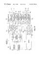
- FIG. 1is a block diagram of a data storage system according to the invention.
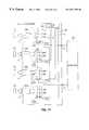
- FIG. 2is a block diagram of a redundant fibre channel network used in the system of FIG. 1 according to the invention
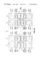
- FIG. 3is a block diagram of a port by-pass section used in the redundant fibre channel network of FIG. 3 coupled to a one of a plurality of disk drive sections in the bank of disk drives used in the system of FIG. 1 according to the invention;
- FIG. 4is a sketch showing the interconnection input/output (I/O) adapters used in the system of FIG. 1 to disk drives and a pair of port-by pass cards used in the redundant fibre channel network of FIG. 2;
- I/Oinput/output
- FIG. 5is a diagram of a cable adapted to transmit both fibre channel signals and non-fibre channel signals
- FIG. 5Ais a cross-sectional sketch of the cable of FIG. 5, such cross-section being taken along line 5 A— 5 A in FIG. 5;
- FIG. 5Bis a diagrammatical sketch showing connections between conductors in the cable of FIG. 5 to pins in one of a pair of connectors of such cable;
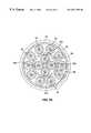
- FIG. 6is a diagrammatical sketch of an elevation view of a disk backplane having plugged therein the disk drives and the pair of port-by pass cards of FIG. 4;
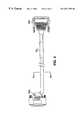
- FIG. 7is an isometric view of a cabinet used to store the disk backplane having plugged therein the disk drives and the pair of port-by pass cards of FIG. 4;
- FIG. 7Ais an exploded view of a portion of the cabinet of FIG. 7, such portion being enclosed by arrow 7 A— 7 A in FIG. 7;
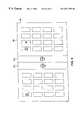
- FIG. 8is a plan view of a portion of the disk backplane of FIG. 6, such disk backplane having a disk drive plugged into one of a plurality of connectors of such disk backplane;
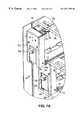
- FIG. 9is an isometric view of housing, or chassis, used for an exemplary one of the disk drives adapted for being plugged into the connector of the disk backplane of FIG. 8;
- FIG. 10is a top view of the housing of FIG. 9, a disk drive being shown in phantom in the chassis;
- FIG. 11is a side view of the housing of FIG. 9, is an enlarged view of the rear portion of the FIG. 10;
- FIG. 12is an enlarged view of the rear portion of the FIG. 10;
- FIG. 12Ais a cross-sectional sketch of a portion of the chassis of FIG. 12, such portion being enclosed with an arrow 12 A— 12 A in FIG. 12;
- FIG. 13is an enlarged view of the rear portion of the FIG. 10, and a disk drive being shown plugged into a cable of the chassis of FIG. 12;
- FIG. 14is a block diagram of a port by-pass section used in the redundant fibre channel network of FIG. 3 coupled to a one of a plurality of disk drive sections in the bank of disk drives used in the system of FIG. 1 according to an alternative embodiment of the invention, such port by-pass section having a pair of port by-pass cards with fail-over control systems according to the invention;
- FIG. 15is a diagram useful in understanding the operation of the port by-pass cards of FIG. 14 with the fail-over control systems according to the invention.
- FIG. 16is a block diagram of a redundant fibre channel network used in the system of FIG. 1, such network having a rear-end I/O adapter with a fibre channel hub according to the invention;
- FIG. 17is a diagram of an exemplary one of a plurality of front-end directors of the system of FIG. 1 coupled to host computer sections through a fibre channel I/O adapter according to the invention;
- FIG. 18is a test printed circuit board adapted to test signal integrity in the system of FIG.1;
- FIG. 19is a diagram showing the relationship between FIGS. 19A and 19B, such FIGS. 19, 19 A and 19 B together showing a system interface of the system of FIG. 1;
- FIG. 20shows slots used in a system backplane of the interface of FIG. 19, each one of such slots having a plurality of pins, the test printed circuit board of FIG. 18 being adapted to test the integrity of the signal at each one of the pins.
- a data storage system 10is shown wherein a host computer 12 is coupled to a bank 14 of disk drives through a system interface 16 .
- the system interface 16includes a cache memory 18 , having a high memory address section 18 H and a low address memory section 18 L.
- a plurality of directors 20 0 - 20 15is provided for controlling data transfer between the host computer 12 and the bank 14 of disk drives as such data passes through the cache memory 18 .
- a pair of high address busses TH, BHis electrically connected to the high address memory section 18 H.
- a pair of low address busses TL, BLis electrically connected to the low address memory section 18 L.
- the cache memory 18has a plurality of storage location addresses.
- each one of the directors 20 0 - 20 15is electrically connected to one of the pair of high address busses TH, BH and one of the pair of low address busses TL, BL.
- each one of the directors 20 0 14 20 15is able to address all locations in the entire cache memory 18 (i.e., to both the high address memory sections 18 H and the low address memory sections 18 L) and is therefore able to store data in and retrieve data from any storage location in the entire cache memory 18 .
- a rear-end portion of the directorshere directors 20 0 - 20 3 and 20 12 - 20 15 , is electrically connected to the bank 14 of disk drives through I/O adapter cards 22 0 - 22 3 and 22 12 B 22 15 , respectively and fibre channel (FC) port by-pass sections 23 1 - 23 8 (described in more detail in connection with FIG. 2 ), respectively.
- a front-end portion of the directors, here directors 20 4 - 20 11is electrically connected to the host computer 12 through I/O adapter cards 22 1 - 22 8 , respectively, as indicated.
- each end of the busses TH, TL, BH, BLterminates in a pair of master and slave arbiters bus arbiters, not shown, as described in co-pending patent application Ser. No. 09/224,194 filed Dec. 30, 1998, entitled DATA STORAGE SYSTEM, inventor Mark Zani, assigned to the same assignee as the present invention, the entire subject matter thereof being incorporated herein by reference.
- the host computer 12issues a write request to one of the front-end directors 20 4 - 20 11 to perform a write command.
- One of the front-end directors 20 4-20 11replies to the request and asks the host computer 12 for the data.
- the directordetermines the size of the data and reserves space in the cache memory 18 to store the request.
- the front-end directorthen produces control signals on either a high address memory bus (TH or BH) or a low memory address bus (TL, BL) connected to such front-end director depending on the location in the cache memory 18 allocated to store the data and enable the transfer to the cache memory 18 .
- TH or BHhigh address memory bus
- TL, BLlow memory address bus
- the host computer 12then transfers the data to the front-end director.
- the front-end directorthen advises the host computer 12 that the transfer is complete.
- the front-end directorlooks up in a Table, not shown, stored in the cache memory 18 to determine which one of the rear-end directors 20 0 - 20 3 and 20 12 - 20 15 is to handle this request.
- the Tablemaps the host computer 12 address into an address in the bank 14 of disk drives.
- the front-end directorthen puts a notification in a “mail box” (not shown and stored in the cache memory 18 ) for the rear-end director which is to handle the request, the amount of the data and the disk address for the data.
- Other rear-end directorspoll the cache memory 18 when they are idle to check their “mail boxes”.
- the rear-end directorprocesses the request, addresses the disk drive in the bank, reads the data from the cache memory and writes it into the addresses of a disk drive in the bank 14 .
- the systemoperates in a reciprocal manner.
- Each one of the rear-end portion of the directors 20 0 - 20 3 and 20 12 - 20 15is identical in construction and are described in detail in the above-referenced co-pending patent application Ser. No. 09/224,194 to include a pair of central processing sections, CPU X and CPU Y, a dual port random access memory (RAM), and shared resources (Flash memories, etc,) coupled to the bank 14 of disk drives (FIG. 1) through the I/O adapter cards 20 0 - 20 3 and 20 12 - 20 15 and the fibre channel (FC) port by-pass sections 23 1 - 23 8 as indicated and to a high memory address bus, here TH, and low memory address bus, here BL.
- THhigh memory address bus
- BLlow memory address bus
- each one of the directors 20 0 - 20 3 and 20 12 - 20 15has a first output port, A, and a second output port, B. Further, it should be noted that different pairs of the rear-end directors 20 0 , 20 1 ; 20 2 , 20 3 ; 20 12 , 20 13 (not shown); and, 20 14 , 20 15 are arranged in redundant fibre channel (FC) networks 25 1 - 25 4 , respectively, as indicated.
- FCfibre channel
- each one of the redundant fibre channel (FC) networks 25 1 - 25 4also includes: pairs of the I/O adapter cards 22 0, 22 1; 22 2, 22 3; 22 4, 22 12 ; 22 13, (not shown); and 22 14 , 22 15 ; fibre channel (FC) port by-pass sections 23 1 , 23 2 ; 23 3 , 23 4 ; 23 5 (not shown), 23 6 (not shown); and, 23 7 , 23 8 , respectively, as indicated and disk drive sets 14 1 , 14 2 ; 14 3 , 14 4 ; 14 5 (not shown), 14 6 (not shown); and, 14 7 , 14 8 , respectively, as indicated.
- Each one of the pairs of the redundant fibre channel (FC) networks 25 1 - 25 4is identical in construction, an exemplary one thereof, here redundant fibre channel (FC) networks 25 1 is shown in detail in FIG. 2 .
- director 20 0is connected to busses TH and BL and that director 20 1 is connected to busses TL and BH.
- the redundant FC network 25 1(FIG. 1) is also coupled, via directors 20 0 and 20 1 to all four busses TH, BH, TL, and BL.
- redundant FC network 25 1For an exemplary one of the redundant FC networks 25 1 - 25 4 , here redundant FC network 25 1 , it is noted that the first port A and second port B of director 20 0 , are connected, through I/O adapter 22 0 , to FC port by-pass section 23 1 and to FC port by-pass section 23 2 , respectively. Likewise, the first port A and second port B of director 20 1 are connected, through I/O adapter 22 1 , to FC port by-pass section 23 1 and to FC port by-pass section 23 2 , respectively.
- Each one of the FC port by-pass sections 23 1 , 23 2includes a pair of FC port by-pass cards 34 1 and 34 2 ; here, an A port by-pass card 34 1 and a B port by-pass card 34 2 .
- Each one of the disk drive sections 14 1 - 14 8(FIG. 1) includes a plurality of, here eight, disk drives, 36 1 - 36 8 , as indicated for disk drive sections 14 1 and 14 2 in FIG. 2, it being understood that the number of disk drives in a section can be selected in accordance with the requisite storage requirements.
- Each one of the disk drives 36 1 - 36 8has a pair of redundant ports, i.e., a Port A and a Port B, as shown. Further, the A port by-pass card 34 1 , of each one of the port by-pass sections 23 1 , 23 2 is connected to the A ports of the disk drives 36 1 - 36 8 in a corresponding one of the disk drive sections 14 1 , 14 2 , respectively, as shown.
- the port A by-pass card 34 1 of port by-pass section 23 1is connected to the A port of the disk drives 36 1 - 36 8 in disk drive section 14 1 and the port A by-pass card 34 1 of port by-pass section 23 2 is connected to the A port of the disk drives 36 1 - 36 8 in disk drive section 14 2 , as shown.
- the B port by-pass card 34 2 ,of each one of the port by-pass sections 23 1 23 2is connected to the B ports of the disk drives 36 1 - 36 8 in a corresponding one of the disk drive sections 14 1 , 14 2 , respectively, as shown.
- the port B by-pass card 34 2 of port by-pass section 23 1is connected to the B port of the disk drives 36 1 - 36 8 in disk drive section 14 1 and the port B by-pass card 34 2 of port by-pass section 23 2 is connected to the B port of the disk drives 36 1 - 36 8 in disk drive section 14 2 , as shown.
- Each one of the FC port by-pass cards 34 1 , 34 2and is identical in construction, an exemplary one thereof, here FC port by-pass 34 1 being shown in detail in FIG. 3 connected between the A ports of the disk drives 36 1 - 36 8 in the set 14 1 of the disk drives and to the I/O adapters 20 0 -directors 20 0 .
- port B by-pass card 34 2 of port by-pass section 23 1is also shown in FIG. 3 connected between the B ports of the disk drives 36 1 - 36 8 in set 14 1 of disk drives and the I/O adapter 22 1 -director 20 1 .
- director 20 0is able to access the disk drives 36 1 - 36 8 in set 14 2 through its port B and, likewise, in the event of a failure in director 20 0, director 20 1 is able to access disk drives 36 1 - 36 8 in set 14 1 through its A port. It is also noted that in the event of a failure of, or removal of, any one of the port A or port B by-pass cards 34 1 , 34 2 , both sets of disk drives 14 1 and 14 2 are still accessible from one of the directors 20 0 and 20 1 .
- the set 14 1 of disk drivesis accessible from director 20 1 , via the path between port A of director 20 1 , the port B by-pass card 34 2 of fibre channel by-pass section 23 1 , and the port B of the disk drives in set 14 1 .
- the set 14 1 of disk drivesis accessible from director 20 0 , via the path between port A of director 20 0 , the port A by-pass 34 1 of fibre channel by-pass section 23 1 , and the port A of the disk drives in set 14 2 .
- the set 14 2 of disk drivesis accessible from director 20 1 , via the path between port B of director 20 1 , the port B by-pass card 34 2 of fibre channel by-pass section 23 2 , and the port B of the disk drives in set 14 2 .
- the set 14 2 of disk drivesis accessible from director 20 0 , via the path between port B of director 20 0 , the port A by-pass 34 1 of fibre channel by-pass section 23 2 , and the port A of the disk drives in set 14 2 .
- Port A by-pass card 34 1 and port B by-pass card 34 2are the same in structure.
- Port A by-pass selector, or multiplexer, card 34 1is adapted to couple the port A of director 20 0 (via I/O adapter 22 0 ) serially to a selected one, or ones, of port A of the plurality of disk drives 36 1 - 36 8 in set 14 1 through a first fibre channel comprising one, or more, of the plurality of fibre channel links 29 A1 - 29 A8
- the fibre channel port by-pass multiplexer card 34 2is adapted to couple the A port of director 20 1 (via the I/O adapter 22 1 ) serially to a selected one, or ones, of the plurality of disk drives 36 1 - 36 8 through fibre channel links 29 B1 - 29 B8 , as indicated, in a manner to be described briefly below and described in detail in copending patent application Ser. No. 09/343,344, filed Jun. 30, 1999.
- the exemplary FC port by-pass card 34 1includes multiplexers 39 1 - 39 11 and a control section 40 .
- Each one of the multiplexers 39 1 - 39 11has a pair of input ports (i.e., an A input and a B input) and an output port, one of the input ports A or B being coupled to the output port selectively in accordance with a control signal C 1 -C 11 , respectively, fed thereto, as indicated, by the control section 40 .
- the operation of the control section 40is described in detail in the above referenced copending patent application Ser. No. 09/343,344 filed Jun.
- port A of director 20 0is coupled serially through disk drives 36 1 - 36 4 of set 14 1 via ports A of such disk drives 36 1 - 36 4 and port B of director 20 1 is coupled serially through disk drives 36 5 - 36 8 of set 14 1 via ports B of such disk drives 36 5 - 36 8 .
- Suchis accomplished by the control signals C 1 -C 11 from director 20 0 on bus 45 0 equivalent control signals from director 20 1 on bus 45 1 to port B by-pass card 34 2 , which couple one of the A and B ports of the multiplexers coupled to the outputs of such multiplexers as described fully in the above referenced patent application Ser. No. 09/343,344
- Port B by-pass card 34 2operates, as noted above to couple the A port of director 20 1 -I
- control sections 40are advised of such failure by the directors 20 0 and 20 1 via control lines 45 0 , 45 1 , respectively.
- control section 40changes the logic state on control line C 4 to thereby de-couple input port A of multiplexer 36 4 from its output and couples input port B of multiplexer 36 4 to its output; thereby by-passing disk drive 36 3 from the fibre channel transmission line segments 41 1 , 41 0 .
- control section 40in port B by-pass card 34 2 changes the logic state on a control line therein to thereby de-couple disk drive 36 7 from the I/O adapter 22 1 -director 20 1
- director 20 0is coupled to the A ports of disk drives 36 1 - 36 4 and director 20 1 is coupled to the B ports of disk drives 36 5 - 36 8 .
- director 20 0is de-coupled from disk drives 36 1 - 36 4 and director 20 1 is coupled to the B ports of disk drives 36 1 - 36 4 in addition to remaining coupled to the B ports of disk drives 36 6 - 36 8 .
- director 20 1is de-coupled from disk drives 36 5 - 36 8 and director 20 0 is coupled to the A ports of disk drives 36 5 - 36 8 in addition to remaining coupled to the A ports of disk drives 36 1 - 36 4 .
- the I/O adapters 22 0 - 22 15are shown plugged into the front side of a system backplane 50 and the directors 22 0 - 22 15 and high and low memories 18 H, 18 L are plugged into rear side of the system backplane 50 .
- the arrangementis shown, and described, in more detail in the above referenced copending patent application Ser. No. 09/224,194.
- the I/O adapters 22 0 - 22 3 and 22 12 - 22 15are connected to the port A by-pass card 34 1 and port B by-pass cards 34 2 of the port by-pass sections 23 1 through 23 8 as discussed above in connection with FIG. 2 .
- the port by-pass section 23 1 through 23 8are arranged in pairs, each pair being a corresponding one of the redundant fibre channel networks 25 1 - 25 4 .
- the I/O adapters 22 0 , 22 1 of such redundant fibre channel network 25 1is connected to the rear side of a disk backplane printed circuit board 54 through cables 52 0 , 52 1 , respectively.
- These cables 52 0 , 52 1will be described in detail in connection with FIG. 5 . Suffice it to say here, however, that each one of the cables 52 0 , 52 1 is adapted to carry both fibre channel signals and non-fibre channel signals.
- FIG. 7shows only two disk drives 36 1 and 36 2 , disk drive 36 2 being shown in a fully inserted position and disk drive 36 1 being shown in a partially inserted position.
- the disk backplane 54is mounted to the rear of the rack 54 , as shown.
- the disk backplane 54has eight electrical connectors 62 (FIG. 8) each in registration with a corresponding one of the slots 36 .
- the connectorsare thus arranged to enable the disk drives 36 1 to here 36 8 to be plugged into the electrical connectors 62 , it being understood that while here eight disk drives 36 1 to 36 8 have been used for illustration, the system is here adapted for use with up to twenty four disk drives.
- the disk drivesare electrically interconnected through conductors, not shown, in the disk backplane 54 .
- FIGS. 9-11an exemplary one of the housings 66 for disk drive 36 1 , the disk drive being shown in phantom in FIGS. 10 and 11, FIG. 9 showing the housing 66 without the disk drive.
- the disk drive chassishas a lock-handle 68 on the front panel thereof and screws 70 mounted on the opposing sides thereof for engagement with the sides of the disk drive, in a conventional manner.
- the disk drive housing 66includes features according to the invention which reduce vibration occurring in the disk drive, from coupling to the rack 56 and thereby coupling through the rack 56 to the other disk drives in the rack 56 . It has been found that when there are many disk drives in the rack 56 , during operation of the disk drives, the vibration through the rack 56 can cause excessive vibration on the disk drives resulting in their malfunction.
- the housing 66is formed with a plurality of, here four, legs 72 , each of which has the resilient material 74 disposed around it, as shown.
- portions of the resilient material 74project beyond the sides of the housing 66 .
- the rack 56(FIGS. 7 and 7 A). has a plurality of horizontal members 76 . Upper and lower pairs of the horizontal members 76 have vertically opposing pairs of slots 78 therein.
- Each opposing pair of slots 78is configured to engage the upper pair and lower pair of legs 72 with the resilient material 74 around such legs 72 . This is more clearly illustrated in FIG. 7 A.
- the resilient memberpresses firmly against the walls of the slots 78 to thereby cushion, and thus suppress, any vibrations produced during operation of the disk drive which may coupled to its housing 66 from coupling to the rack 56 . That is, the vibrations coupled to the housing are dampened by the resilient, shock absorbing material 74 around the legs 72 and such vibrations are thereby de-coupled from the rack 56 .
- a second technique used to decouple vibration produced during operation of the disk drive from the rack 56is through the electrical interconnect arrangement used to connect the disk drive to the connector 62 (FIG. 8) on the disk backplane 54 .
- a flexible ribbon-type, or strap-type, electrical connector 57(FIGS. 9 , 12 , and 13 ) having a mounting member 59 (FIGS.12 and 12A) attached thereto to the rear of the ribbon-type connector 77 is used.
- the mounting member 59has oval-shaped holes 61 (FIG. 12A) for receiving mounting screws 63 .
- the rear of the housing 66is provided with a mounting plate 65 .
- the mounting plate 65has a pair of screw receiving fixtures 67 attached thereto for receiving the mounting screws 63 after the holes 61 are aligned with fixtures 67 .
- the screws 63have a shoulder 69 which spaces the head of the screw 63 from the mounting member 59 when the screw is tightly threaded into the fixture 67 .
- the shoulder 69thus causes a gapG 1 between the mounting member and the head of the screw 63 .
- the oval-shaped hole 61allows for lateral back-and-forth movement of the screw 63 in the hole 61 even after the screw is threaded into the fixture 67 , such back-and-forth movement being indicated by the arrows A in FIG. 12 A.
- the arrangementis designed such that when the mounting member 59 is screwed to the mounting plate 65 with the screws 63 , the mounting member 59 is prevented from being rigidly secured to the mounting plate 65 . This is accomplished by constructing the screws 63 so that when fully inserted into their mating threaded holes, the shoulder 69 and oval-shaped holes 61 Referring to FIG. 13, the plug 71 of the flexible ribbon-type, or strap-type, electrical connector 57 is shown engaged with the plug 73 at the rear of the disk drive 36 1 . With such an arrangement as vibrations in the drive couple to the chassis and thus to the ribbon mounting member, such vibration will not could to the mounting plate because the two are not rigidly attached one to the other because of the mechanism described above.
- the exemplary cable 52 0is adapted to carry both fibre channel signals and non-fibre channel signals.
- the fibre channel signalsinclude the data for storage in the disk drives and the non-fibre channel signals include the control signals described above for controlling the multiplexers in the port by-pass cards as well as other control signals for controlling the operation of the disk drives. It is noted that both the fibre channel signals and the non-fibre channel signals pass through the same cable. Thus, a single connector is used at each end of the cable for both the fibre channel signals and the non-fibre channel signals.
- the cable 52 0is shown to have a central dielectric core 80 .
- the corehas around it the conventional quadrature-pair of electrically insulated conductors 82 a - 82 d arranged for transmission of two pair of differential fibre channel signals.
- One pair of signalsi.e., the signals of conductors 82 a and 82 b are the data from the I/O adapter to the port by-pass card, e.g., the data on 41 1 in FIG.
- the signals of conductors 82 c and 82 dare the data from the port by-pass card to the I/O adapter, e.g., the data on 41 0 in FIG. 3 ).
- Disposed around the quadrature-pair of electrically insulated conductors 82 a - 82 dis an inner conductive shield 86 .
- Disposed around the inner conductive shield 86are a plurality, here ten regularly spaced electrically insulated electrical conductors 88 which carry the non-fibre channel signals. e.g., for control signals.
- Disposed round the electrically insulated conductors 88is an outer conductive shield 92 .
- Disposed around the outer conductive shield 92is a rubber-like sheath 94 .
- the ends of the conductors 82 a - 82 d and the ends of the ten conductors 86are connected to lugs, or pins 85 , at each of a pair of plugs 94 a, 94 b, as shown more clearly in FIG. 5B for plug 94 a.
- the inner conductive shield 86is connected to one of the lugs and the outer conductive shield 92 is connected to the conductive outer housing 93 of the plugs 94 a, 94 b. It is noted that each of the plugs is here a conventional 25-pin plug, thus here not all of the 25 pins are used.
- the fibre channel datapasses through an inner, electro-statically shielded region of the transmission media provided by the cable and the control signals pass through an outer, electro-statically shielded region of the transmission media provided by the cable. Further is noted that only one plug is required at each end of the cable transmission of both the fiber channel signals and the non-fibre channel signals.
- FIG. 14an alternative embodiment of the port by-pass card 34 , here exemplary port A by-pass card 34 1 ′, is shown in detail together with a B port by-pass card 34 ′ 2 , and the disk drive section 14 1 coupled to the port A and port B by pass cards 34 ′ 1 and 34 ′ 2 , as indicated.
- Each one of the port by-pass cards 34 ′ 1 and 34 ′ 2is identical in construction.
- a fail-over controller 100is provided together with a fail-over switch 102 .
- the fail-over controller 100 of the port A by-pass card 34 ′ 1is used to detect a signal from the director 20 0 via the I/O adapter 22 0 indicating that there is some “software” type error, as distinguished from a “hardware” type error, in the operation of the director 20 1 .
- a signal from the director 20 0 via the I/O adapter 22 0indicating that there is some “software” type error, as distinguished from a “hardware” type error, in the operation of the director 20 1 .
- one type of “software” error in director 20 1may cause director 20 1 to continue to request access to the disk drives in section 14 1 ; and such excessive “busy” is detected by director 20 0 .
- the director 20 0issues a fail-over command to the fail-over controller 100 in the A port by-pass card 34 ′ 1 .
- the fail-over controller 100 of the A port by-pass card 34 1produces a switching signal on line 104 for the fail-over switch 102 in the port B by-pass card 34 2 .
- the switch 102 in the port B by-pass card 34 ′ 2opens in response to the switching signal on line 104 thereby de-coupling the director 20 1 from the disk drives 36 1 through 36 8 in the disk drive section 14 1 .
- the switch 102is in series with bus 41 1 described above in connection with FIG. 3 .
- bus 41 1is, when switch 102 is normally (i.e., during the normal, non-fail-over mode when switch 102 is closed) coupled to the A input of multiplexer 39 1 as described above in connection with FIG. 3 .
- the switch 102 in the port B by-pass card 34 ′ 2opens in response to the switching signal on line 104 to de-couple the director 20 1 from the B ports of the disk drives 36 1 - 36 8 in the disk drive section 14 1 .
- the fail-over controller 100 of the port B by-pass card 34 ′ 2is used to detect a signal from the director 20 1 via the I/O adapter 22 1 indicating that there is some “software” type error, as distinguished from a “hardware” type error, in the operation of the director 20 0 .
- the director 20 1issues a fail-over command to the fail-over controller 100 in the port B by-pass card 34 ′ 2 .
- the fail-over controller 100 of the port B by-pass card 34 2produces a switching signal on line 106 for the fail-over switch 102 in the port A by-pass card 34 ′ 1 .
- the switch 102 in the port A by-pass card 34 ′ 1opens in response to the switching signal on line 106 thereby de-coupling the director 20 1 from the disk drives 36 1 through 36 8 in the disk drive section 14 1 .
- line 104 and 106are disposed in the disk backplane 54 (FIG. 4 ).
- the fail-over controllers 100provide port by-pass control via fail-over commands (e.g., reset and power control). This function is provided to effect a smooth and reliable transition in the case of as director fail-over when one director has to be taken out of the fibre channel “loop”.
- the fail-over controllers 100are able to process three commands:Card Reset, Card Power Off, and Card Power On. The sequence of these commands is as follows, considering exemplary the fail-over controller 100 of the port A by-pass card 34 1 : The command bus 108 to the fail-over controller 100 of the port A by-pass card 34 ′ 1 , from its associated (i.e., coupled) director 20 0 must start at Idle.
- a Command Verify commandis issued by the associated director 20 0 .
- one of the action commands(Reset, Card Power On, Card Power Off) is issued, followed by an Execute_ ⁇ type>command where ⁇ type> is the desired action. If this sequence is followed, then when the Execute command is issued, the action will be performed by the remote port by-pass card, here the port B port by-pass card 34 ′ 2 .
- the bus 108then returns to Idle.
- the command bus 108 that carries these commandshas three data bits plus a parity bit. Theses four bits form sixteen codes, as described below:
- the control sequenceis designed to detect hardware failures in the control bus 108 by forcing the bus state from idle (000) to Command Verify (111) to start the command sequence.
- the actual command of the combination code and the binary inversee.g., Card Reset ⁇ 001> and Execute Reset ⁇ 110>
- This sequence controlprovides protection from code faults or execution errors that inadvertently write data to the fail-cover controller 100 .
- the sequence state diagramis shown in FIG. 15 .
- I/O adapters 22 ′ 0 , 22 ′ 1 and port by-pass sections 23 ′ 1 , 23 ′ 2are shown for use in the redundant fibre channel networks 25 1 - 25 4 (FIG. 1) here, in FIG. 16, being shown for exemplary redundant fibre channel network 25 ′.
- the I/O adapters 22 ′ 0 and 22 ′ 1 of network 25 1each include a pair of fibre channel switching hubs 80 A, 80 B, as shown.
- Each one of the hubs 80 A and 80 Bare identical in construction, an exemplary one thereof, here the hub 80 A of I/O adapter 22 ′ 0 being shown in detail.
- Such hub 80 Ais shown to include a fibre channel input 82 connected to the A port of the director 20 0 . It is noted that the hub 80 B of I/O adapter 22 ′ 0 is coupled to the B port of director 20 0 . In like manner, the hub 80 A of I/O adapter 22 ′ 1 is coupled to the A port of director 20 1 and the hub 80 B of I/O adapter 22 ′ 1 is coupled to the B port of director 20 1 , as indicated. It should be noted that here the number of disk drives in each disk drive section 14 ′ 1 and 14 ′ 2 have doubled from eight to here sixteen (i.e., disk drives 36 1 to 36 16 .
- such hubis shown to include drivers 84 , 86 . 88 , 90 , 92 , and 94 and multiplexers 96 and 98 , all arranged as shown.
- the one of the pair of input ports of the multiplexers 96 , 98 is coupled to its outputis selected by the control signal fed to lines 100 and 102 , respectively, as indicated.
- the control signal on line 100is fed to multiplexer 96 and the control signal on line 102 is fed to multiplexer 102 .
- the control signals on lines 100 and 102are produced by the director 20 1 for the hubs 80 A and 80 B in I/O adapter 22 ′ 0 and the equivalent control signals for the hubs 80 A and 80 B of I/O adapters 22 ′ 0 are produced by the director 20 1 .
- each oneis identical in construction, an exemplary one thereof, here section 23 ′ 1 being shown in detail to include a port A by-pass card 34 ′ 1 and a port B by-pass card 34 ′ 2 .
- each port by-pass card 34 ′ 1 and 34 ′ 2includes two redundant ones of the port by-pass cards described above in connection with FIG. 3 .
- the upper port A by-pass card 34 1services eight disk drives in disk drive section 14 1
- the lower port A by-pass card 34 1services another set of here eight disk drives in disk drive section 14 ′ 1 .
- the hub 80 Aenables many different coupling configurations with the disk drive sections 14 1 and 14 ′ 1 depending on the logic state of the signals provided by the director 20 0 to control lines 100 and 102 of the multiplexers 96 , 98 .
- the data from the A port of director 20 0is passed through driver 84 , then through driver 88 then to the upper port A by-pass card 34 1 , then to driver 90 then through multiplexer 100 and back to the A port of the director 20 0 through driver 86 , thus by-passing the lower port A by-pass card 34 1 .
- the data from the A port of director 20 0is passed through driver 84 , then through multiplexer 102 , then through driver 94 , then through the lower port A by-pass card 34 1 , then to driver 92 then through multiplexer 100 and back to the A port of the director 20 0 through driver 86 , thus by-passing the upper port A by-pass card 34 1 .
- the data from the A port of director 20 0is passed through driver 84 , then driver 88 then through the upper port A by-pass card 34 1 , then through driver 90 , then through multiplexer 102 , then through driver 94 , then to the lower A port by-pass card 34 1 , then through driver 92 , then through multiplexer 100 , then back to the A port of director 20 0 through driver 86 .
- I/O adapter 22 4having a pair of ports P 1 , P 2 adapted for coupling to director 20 4 and a plurality of, here four, ports P 3 -P 6 adapted for communication with the host computer, here four host computer sections 12 1 - 12 4 of the host computer 12 (FIG. 1) through a fiber channel hub 201 .
- the hub 201 of I/O adapter 22 4includes a plurality of electro-optical transceivers 200 1 - 200 4 , each one including a laser for transmitting data to the host computer section coupled thereto and a laser receiver for receiving data from such coupled host computer section.
- transceivers 200 1 - 200 4are coupled to host computer sections 12 1 - 12 4 , respectively, as indicated. Each one of the transceivers 200 1 - 200 4 is coupled to a corresponding one of a plurality of, here four, switching sections 202 1 - 202 4 respectively as indicated. Each one of the switching sections includes a receiver re-timer 204 , a transmit retimer 206 and a multiplexer 208 , arranged as shown. Each one of the multiplexers 208 in section 202 1 - 202 4 is controlled by control signals on lines L 1 -L 4 , respectively as indicated. The control signals on lines L 1 -L 4 are supplied by a multiplexer controller 210 . The control signals supplied by the multiplexer controller 210 are produced in accordance with a control signal supplied by the director 204 coupled to the I/O adapter 22 4 .
- the arrangementcontrols the distribution between director 20 4 and a selected one, or ones of the host computer sections 200 1 - 200 4 . More particularly, and considering data from the director 20 4 to the data from the director 20 4 , such data passes to an input of multiplexer section 202 4 . The data is able to pass to the transceiver 200 4 or pass to multiplexer section 202 3 selectively in accordance with the control signal on line L 4 . Thus, if it is desired to communicate with host computer section 12 4 , the control signal on line L 1 selects port A of multiplexer 208 in section 202 4 .
- control signal on line L 4causes the data at the B port of the multiplexer 208 of such multiplexer section 202 4 to pass directly to the output of such section 202 4 .
- port Awhen port A is selected to enable communication with the host computer section 12 4 , the data passes to the host computer section 12 4 via the transmit re-timer 206 and data from the host computer section 12 4 via the receive re-timer 204 .
- each one of the front-end directorshas a pair of ports and therefore the I/O adapter connected to such director has a pair hubs 201 each one being coupled to a corresponding one of the ports of the front-end director.
- FIG. 18a method for testing the signal integrity of the signals on the system backplane 50 (FIG. 4) will be described.
- the directors 20 0 - 20 15 and I/O adapters 22 0 - 22 15are plugged into an array of slots on opposite sides in the system backplane 50 .
- the arrangementis described in more detail in the above-referenced copending patent application Ser. No. 09/224,194 filed Dec. 30, 1998, entitled DATA STORAGE SYSTEM, inventor Mark Zani.
- the system backplane 50 nhas a plurality of slots 32 0 - 32 19 , the slots in the front surface thereof being adapted to receive the front-end and the rear-end directors and the memories and the slots in the back surface thereof being adapted to receive the front-end and the rear-end I/O adapters.
- Each slothas a large plurality of pins for receiving the directors, I/O adapters and memories, as shown in FIGS. 18A and 19B.
- the buses TH, TL, BH, and BLappear to the high-speed data thereon as transmission lines.
- the system backplane 50has typically several hundred pins for each director slot.
- the following test procedureis used to test the signal integrity at each one of the slots. It should be understood that because of different loading effects at various slots along the busses, the waveform of the signals on a bus would appear slightly different from slot to slot.
- a test board, or card 300is provided, such test board 300 being shown in FIG. 18 .
- the test board 300is adapted to replace, during a test mode, each one of the directors and memories and thereby enable the signal waveforms at the pins in the slot occupied by such one of the directors and memories to be examined.
- the test board 300is shown to include a plurality of transceivers 302 coupled to each one of the pins of the board 300 .
- the transceivers 302are coupled to a multiplexer section 304 .
- the multiplexer sectionhas seven multiplexers 303 1 - 307 7 , it being understood that for several hundred pins there would be a significantly larger number of multiplexers.
- the board 300has a multiplexer control section 306 which produces control signal on line N 1 -N 7 for each one of the multiplexers in the multiplexer section 304 . In response to the control signals a selected one of the pins is thereby coupled to an output port P O of the test card 300 .
- the signal at each one of the pinscan be selectively coupled to the output port P O .
- the output port P 0is coupled to a scope 310 .
- a personal computer PC 312is used to control the multiplexer control section 306 and scope 310 .
- the signal at each one of the pinsis sequentially examined with the scope 310 and recorded in the PC 312 .
- the test board 300is placed in one of the slots 32 0 - 32 15 . After testing the signal waveform at each of the pins at that slot, the test board is plugged into a different one of the slots and the process is repeated for the newly positioned test board.
- the processis repeated until the signal waveform at each one of the pins in at slot and at each one of the slots is individually analyzed with the backplane 50 under fully loaded conditions (i.e., with the directors and memories, other than the director or memory normally in the slot being tested) and the I/O adapters plugged into the system backplane.
Landscapes
- Engineering & Computer Science (AREA)
- Theoretical Computer Science (AREA)
- Quality & Reliability (AREA)
- Physics & Mathematics (AREA)
- General Engineering & Computer Science (AREA)
- General Physics & Mathematics (AREA)
- Computer Networks & Wireless Communication (AREA)
- Signal Processing (AREA)
- Debugging And Monitoring (AREA)
- Hardware Redundancy (AREA)
Abstract
Description
| C2 | C1 | Parity | Description | |||
| 0 | 0 | 0 | 0 | Parity Error (PE) | ||
| 0 | 0 | 0 | 1 | Idle | ||
| 0 | 0 | 1 | 0 | |||
| 0 | 0 | 1 | 1 | |||
| 0 | 1 | 0 | 0 | |||
| 0 | 1 | 0 | 1 | |||
| 0 | 1 | 1 | 0 | |||
| 0 | 1 | 1 | 1 | Execute Power On | ||
| 9 | 0 | 0 | 0 | |||
| 1 | 0 | 0 | 1 | |||
| 1 | 0 | 1 | 0 | |||
| 1 | 0 | 1 | 1 | Execute | ||
| 1 | 1 | 0 | 0 | |||
| 1 | 1 | 0 | 1 | Execute | ||
| 1 | 1 | 1 | 0 | Command Verify | ||
| 1 | 1 | 1 | 1 | PE | ||
Claims (4)
Priority Applications (2)
| Application Number | Priority Date | Filing Date | Title |
|---|---|---|---|
| US09/474,112US6571355B1 (en) | 1999-12-29 | 1999-12-29 | Fibre channel data storage system fail-over mechanism |
| EP00311737AEP1113363B1 (en) | 1999-12-29 | 2000-12-28 | Fibre channel data storage system fail-over mechanism |
Applications Claiming Priority (1)
| Application Number | Priority Date | Filing Date | Title |
|---|---|---|---|
| US09/474,112US6571355B1 (en) | 1999-12-29 | 1999-12-29 | Fibre channel data storage system fail-over mechanism |
Publications (1)
| Publication Number | Publication Date |
|---|---|
| US6571355B1true US6571355B1 (en) | 2003-05-27 |
Family
ID=23882226
Family Applications (1)
| Application Number | Title | Priority Date | Filing Date |
|---|---|---|---|
| US09/474,112Expired - LifetimeUS6571355B1 (en) | 1999-12-29 | 1999-12-29 | Fibre channel data storage system fail-over mechanism |
Country Status (2)
| Country | Link |
|---|---|
| US (1) | US6571355B1 (en) |
| EP (1) | EP1113363B1 (en) |
Cited By (68)
| Publication number | Priority date | Publication date | Assignee | Title |
|---|---|---|---|---|
| US20010014956A1 (en)* | 2000-02-10 | 2001-08-16 | Hitachi, Ltd. | Storage subsystem and information processing system |
| US20010056304A1 (en)* | 2000-04-19 | 2001-12-27 | Kabushiki Kaisha Toshiba | Field apparatus control system and computer-readable storage medium |
| US20030101369A1 (en)* | 2001-11-29 | 2003-05-29 | International Business Machines Corporation | Method, system, and program for error handling in a dual adaptor system |
| US20030101371A1 (en)* | 2001-11-29 | 2003-05-29 | International Business Machines Corporation | Method, system, and program for error handling in a dual adaptor system where one adaptor is a master |
| US20030140277A1 (en)* | 2002-01-19 | 2003-07-24 | International Business Machines Corporation | Method and apparatus for relating device name to physical location of device on a network |
| US20040081087A1 (en)* | 2002-09-09 | 2004-04-29 | Shea Michael John | Method, apparatus and program storage device for verifying existence of a redundant fibre channel path |
| US6766482B1 (en) | 2001-10-31 | 2004-07-20 | Extreme Networks | Ethernet automatic protection switching |
| US20040153914A1 (en)* | 2003-01-17 | 2004-08-05 | El-Batal Mohamad H. | System and method for isolating a faulty switch, storage device or SFP in a daisy-chained configuration |
| US20040153702A1 (en)* | 2002-08-09 | 2004-08-05 | Bayus Mark Steven | Taking a resource offline in a storage network |
| US6775230B1 (en)* | 2000-07-18 | 2004-08-10 | Hitachi, Ltd. | Apparatus and method for transmitting frames via a switch in a storage area network |
| US20040184721A1 (en)* | 2003-03-18 | 2004-09-23 | Birmingham Irving M. | Providing reconditioned signals at a plurality of ports |
| US20040193973A1 (en)* | 2003-03-31 | 2004-09-30 | Ofer Porat | Data storage system |
| US20040250181A1 (en)* | 2003-06-05 | 2004-12-09 | Intel Corporation | Memory channel with bit lane fail-over |
| US20050010843A1 (en)* | 2003-07-11 | 2005-01-13 | Koji Iwamitsu | Storage system and a method for diagnosing failure of the storage system |
| US20050025045A1 (en)* | 2003-07-30 | 2005-02-03 | Norio Shimozono | Switch provided with capability of switching a path |
| US20050086426A1 (en)* | 2003-10-16 | 2005-04-21 | International Business Machines Corporation | Load balancing to support tape and disk subsystems on shared fibre channel adapters |
| US6898730B1 (en)* | 2001-11-30 | 2005-05-24 | Western Digital Technologies, Inc. | System and method for fail-over switching in a disk storage medium |
| US20050188239A1 (en)* | 2004-01-30 | 2005-08-25 | Dell Products L.P. | Method, software and system for multi-path fail-over recovery in sequential storage systems |
| US20050188257A1 (en)* | 2004-02-04 | 2005-08-25 | Seiki Morita | Anomaly notification control in disk array |
| US20050278581A1 (en)* | 2004-05-27 | 2005-12-15 | Xiaoming Jiang | Storage control system and operating method for storage control system |
| US6990530B1 (en) | 2001-06-29 | 2006-01-24 | Sun Microsystems, Inc. | Method and apparatus for fault isolation on network loops |
| US7324500B1 (en)* | 2000-10-31 | 2008-01-29 | Jeremy Benjamin As Receiver For Chiaro Networks Ltd. | Router network protection using multiple facility interfaces |
| US20080074998A1 (en)* | 2003-01-09 | 2008-03-27 | Becker Wiren D | Self-healing chip-to-chip interface |
| US20080126698A1 (en)* | 2006-09-13 | 2008-05-29 | Hitachi, Ltd. | Storage system effectively using free ports |
| US20100011176A1 (en)* | 2008-07-11 | 2010-01-14 | Burkey Todd R | Performance of binary bulk IO operations on virtual disks by interleaving |
| US7702757B2 (en) | 2004-04-07 | 2010-04-20 | Xiotech Corporation | Method, apparatus and program storage device for providing control to a networked storage architecture |
| US20130315586A1 (en)* | 2012-05-23 | 2013-11-28 | Brocade Communications Systems, Inc. | Terabit top-of-rack switch |
| US8694825B2 (en) | 2011-07-20 | 2014-04-08 | International Business Machines Corporation | Protecting storage fabrics from errant device causing single point of failure |
| US9116807B2 (en) | 2012-08-15 | 2015-08-25 | International Business Machines Corporation | Handling intermittent recurring errors in a network |
| US9548873B2 (en) | 2014-02-10 | 2017-01-17 | Brocade Communications Systems, Inc. | Virtual extensible LAN tunnel keepalives |
| US9565099B2 (en) | 2013-03-01 | 2017-02-07 | Brocade Communications Systems, Inc. | Spanning tree in fabric switches |
| US9608833B2 (en) | 2010-06-08 | 2017-03-28 | Brocade Communications Systems, Inc. | Supporting multiple multicast trees in trill networks |
| US9628336B2 (en) | 2010-05-03 | 2017-04-18 | Brocade Communications Systems, Inc. | Virtual cluster switching |
| US9626255B2 (en) | 2014-12-31 | 2017-04-18 | Brocade Communications Systems, Inc. | Online restoration of a switch snapshot |
| US9628293B2 (en) | 2010-06-08 | 2017-04-18 | Brocade Communications Systems, Inc. | Network layer multicasting in trill networks |
| US9628407B2 (en) | 2014-12-31 | 2017-04-18 | Brocade Communications Systems, Inc. | Multiple software versions in a switch group |
| US9678680B1 (en)* | 2015-03-30 | 2017-06-13 | EMC IP Holding Company LLC | Forming a protection domain in a storage architecture |
| US9699117B2 (en) | 2011-11-08 | 2017-07-04 | Brocade Communications Systems, Inc. | Integrated fibre channel support in an ethernet fabric switch |
| US9699029B2 (en) | 2014-10-10 | 2017-07-04 | Brocade Communications Systems, Inc. | Distributed configuration management in a switch group |
| US9716672B2 (en) | 2010-05-28 | 2017-07-25 | Brocade Communications Systems, Inc. | Distributed configuration management for virtual cluster switching |
| US9736085B2 (en) | 2011-08-29 | 2017-08-15 | Brocade Communications Systems, Inc. | End-to end lossless Ethernet in Ethernet fabric |
| US9742693B2 (en) | 2012-02-27 | 2017-08-22 | Brocade Communications Systems, Inc. | Dynamic service insertion in a fabric switch |
| US9769016B2 (en) | 2010-06-07 | 2017-09-19 | Brocade Communications Systems, Inc. | Advanced link tracking for virtual cluster switching |
| US9774543B2 (en) | 2013-01-11 | 2017-09-26 | Brocade Communications Systems, Inc. | MAC address synchronization in a fabric switch |
| US9800471B2 (en) | 2014-05-13 | 2017-10-24 | Brocade Communications Systems, Inc. | Network extension groups of global VLANs in a fabric switch |
| US9807031B2 (en) | 2010-07-16 | 2017-10-31 | Brocade Communications Systems, Inc. | System and method for network configuration |
| US9807007B2 (en) | 2014-08-11 | 2017-10-31 | Brocade Communications Systems, Inc. | Progressive MAC address learning |
| US9807005B2 (en) | 2015-03-17 | 2017-10-31 | Brocade Communications Systems, Inc. | Multi-fabric manager |
| US9806906B2 (en) | 2010-06-08 | 2017-10-31 | Brocade Communications Systems, Inc. | Flooding packets on a per-virtual-network basis |
| US9807017B2 (en) | 2013-01-11 | 2017-10-31 | Brocade Communications Systems, Inc. | Multicast traffic load balancing over virtual link aggregation |
| US9848040B2 (en) | 2010-06-07 | 2017-12-19 | Brocade Communications Systems, Inc. | Name services for virtual cluster switching |
| US9887916B2 (en) | 2012-03-22 | 2018-02-06 | Brocade Communications Systems LLC | Overlay tunnel in a fabric switch |
| US9912612B2 (en) | 2013-10-28 | 2018-03-06 | Brocade Communications Systems LLC | Extended ethernet fabric switches |
| US9912614B2 (en) | 2015-12-07 | 2018-03-06 | Brocade Communications Systems LLC | Interconnection of switches based on hierarchical overlay tunneling |
| US9942097B2 (en) | 2015-01-05 | 2018-04-10 | Brocade Communications Systems LLC | Power management in a network of interconnected switches |
| US10003552B2 (en) | 2015-01-05 | 2018-06-19 | Brocade Communications Systems, Llc. | Distributed bidirectional forwarding detection protocol (D-BFD) for cluster of interconnected switches |
| US10038592B2 (en) | 2015-03-17 | 2018-07-31 | Brocade Communications Systems LLC | Identifier assignment to a new switch in a switch group |
| US10063473B2 (en) | 2014-04-30 | 2018-08-28 | Brocade Communications Systems LLC | Method and system for facilitating switch virtualization in a network of interconnected switches |
| US10164883B2 (en) | 2011-11-10 | 2018-12-25 | Avago Technologies International Sales Pte. Limited | System and method for flow management in software-defined networks |
| US10171303B2 (en) | 2015-09-16 | 2019-01-01 | Avago Technologies International Sales Pte. Limited | IP-based interconnection of switches with a logical chassis |
| US10237090B2 (en) | 2016-10-28 | 2019-03-19 | Avago Technologies International Sales Pte. Limited | Rule-based network identifier mapping |
| US10277464B2 (en) | 2012-05-22 | 2019-04-30 | Arris Enterprises Llc | Client auto-configuration in a multi-switch link aggregation |
| US10439929B2 (en) | 2015-07-31 | 2019-10-08 | Avago Technologies International Sales Pte. Limited | Graceful recovery of a multicast-enabled switch |
| US10476698B2 (en) | 2014-03-20 | 2019-11-12 | Avago Technologies International Sales Pte. Limited | Redundent virtual link aggregation group |
| US10579406B2 (en) | 2015-04-08 | 2020-03-03 | Avago Technologies International Sales Pte. Limited | Dynamic orchestration of overlay tunnels |
| US10581758B2 (en) | 2014-03-19 | 2020-03-03 | Avago Technologies International Sales Pte. Limited | Distributed hot standby links for vLAG |
| US10616108B2 (en) | 2014-07-29 | 2020-04-07 | Avago Technologies International Sales Pte. Limited | Scalable MAC address virtualization |
| US11347520B2 (en)* | 2020-02-13 | 2022-05-31 | Dell Products L.P. | Unavailable memory device initialization system |
Families Citing this family (3)
| Publication number | Priority date | Publication date | Assignee | Title |
|---|---|---|---|---|
| US7383399B2 (en) | 2004-06-30 | 2008-06-03 | Intel Corporation | Method and apparatus for memory compression |
| DE102005057122A1 (en)* | 2005-11-30 | 2007-05-31 | Siemens Ag | Ethernet network, has switches which are formed in network start-up phase by distribution of special telegrams to configure active and inactive coupling channels in distortion free operation |
| US20130279769A1 (en) | 2012-04-10 | 2013-10-24 | Picofield Technologies Inc. | Biometric Sensing |
Citations (25)
| Publication number | Priority date | Publication date | Assignee | Title |
|---|---|---|---|---|
| US5206939A (en) | 1990-09-24 | 1993-04-27 | Emc Corporation | System and method for disk mapping and data retrieval |
| US5212785A (en)* | 1990-04-06 | 1993-05-18 | Micro Technology, Inc. | Apparatus and method for controlling data flow between a computer and memory devices |
| EP0550853A2 (en) | 1992-01-07 | 1993-07-14 | Mitsubishi Denki Kabushiki Kaisha | Array of disk drives with redundant channels |
| EP0751464A1 (en) | 1995-06-26 | 1997-01-02 | Hewlett-Packard Company | Storage system |
| WO1997007458A1 (en) | 1995-08-15 | 1997-02-27 | Emc Corporation | Data storage system |
| WO1998028882A1 (en) | 1996-12-23 | 1998-07-02 | Symbios, Inc. | Dynamic topology configuration in a daisy-chained communication environment |
| EP0889410A2 (en) | 1997-06-26 | 1999-01-07 | Sun Microsystems, Inc. | Method and apparatus for high availability and caching data storage devices |
| US5890214A (en) | 1996-02-27 | 1999-03-30 | Data General Corporation | Dynamically upgradeable disk array chassis and method for dynamically upgrading a data storage system utilizing a selectively switchable shunt |
| US5898828A (en) | 1995-12-29 | 1999-04-27 | Emc Corporation | Reduction of power used by transceivers in a data transmission loop |
| WO1999026146A1 (en) | 1997-11-14 | 1999-05-27 | Sun Microsystems, Inc. | Partitioning of storage channels using programmable switches |
| US5922077A (en)* | 1996-11-14 | 1999-07-13 | Data General Corporation | Fail-over switching system |
| US5991891A (en)* | 1996-12-23 | 1999-11-23 | Lsi Logic Corporation | Method and apparatus for providing loop coherency |
| US6038618A (en)* | 1996-10-08 | 2000-03-14 | International Business Machines Corporation | Bypass circuit for bypassing host computer which are connected to plurality of devices via two individual ports upon detecting lack of communication at both ports |
| US6061753A (en) | 1998-01-27 | 2000-05-09 | Emc Corporation | Apparatus and method of accessing target devices across a bus utilizing initiator identifiers |
| US6118776A (en) | 1997-02-18 | 2000-09-12 | Vixel Corporation | Methods and apparatus for fiber channel interconnection of private loop devices |
| US6138199A (en) | 1997-01-23 | 2000-10-24 | Sun Microsystems, Inc. | System for data transfer in a ring topology comprising selectors to selectively bypass external devices or a downstream device based upon presence indications |
| US6154791A (en) | 1997-06-10 | 2000-11-28 | International Business Machines Corporation | Communication system for an array of direct access storage devices (DASD) that provides for bypassing one or multiple DASD |
| US6185203B1 (en) | 1997-02-18 | 2001-02-06 | Vixel Corporation | Fibre channel switching fabric |
| US6192027B1 (en) | 1998-09-04 | 2001-02-20 | International Business Machines Corporation | Apparatus, system, and method for dual-active fibre channel loop resiliency during controller failure |
| US6195703B1 (en) | 1998-06-24 | 2001-02-27 | Emc Corporation | Dynamic routing for performance partitioning in a data processing network |
| US6219753B1 (en) | 1999-06-04 | 2001-04-17 | International Business Machines Corporation | Fiber channel topological structure and method including structure and method for raid devices and controllers |
| US6260079B1 (en) | 1998-11-15 | 2001-07-10 | Hewlett-Packard Company | Method and system for enhancing fibre channel loop resiliency for a mass storage enclosure by increasing component redundancy and using shunt elements and intelligent bypass management |
| US6282169B1 (en) | 1999-06-11 | 2001-08-28 | Amplify.Net Inc. | Serial redundant bypass control mechanism for maintaining network bandwidth management service |
| US20020012342A1 (en) | 1997-03-31 | 2002-01-31 | Barry J. Oldfield | Fibre channel arbitrated loop dynamic loop sizing |
| US6389494B1 (en) | 1998-12-30 | 2002-05-14 | Emc Corporation | System for interfacing a data storage system to a host utilizing a plurality of busses for carrying end-user data and a separate bus for carrying interface state data |
- 1999
- 1999-12-29USUS09/474,112patent/US6571355B1/ennot_activeExpired - Lifetime
- 2000
- 2000-12-28EPEP00311737Apatent/EP1113363B1/ennot_activeExpired - Lifetime
Patent Citations (27)
| Publication number | Priority date | Publication date | Assignee | Title |
|---|---|---|---|---|
| US5212785A (en)* | 1990-04-06 | 1993-05-18 | Micro Technology, Inc. | Apparatus and method for controlling data flow between a computer and memory devices |
| US5206939A (en) | 1990-09-24 | 1993-04-27 | Emc Corporation | System and method for disk mapping and data retrieval |
| EP0550853A2 (en) | 1992-01-07 | 1993-07-14 | Mitsubishi Denki Kabushiki Kaisha | Array of disk drives with redundant channels |
| EP0751464A1 (en) | 1995-06-26 | 1997-01-02 | Hewlett-Packard Company | Storage system |
| WO1997007458A1 (en) | 1995-08-15 | 1997-02-27 | Emc Corporation | Data storage system |
| US5729763A (en) | 1995-08-15 | 1998-03-17 | Emc Corporation | Data storage system |
| US5898828A (en) | 1995-12-29 | 1999-04-27 | Emc Corporation | Reduction of power used by transceivers in a data transmission loop |
| US5890214A (en) | 1996-02-27 | 1999-03-30 | Data General Corporation | Dynamically upgradeable disk array chassis and method for dynamically upgrading a data storage system utilizing a selectively switchable shunt |
| US6038618A (en)* | 1996-10-08 | 2000-03-14 | International Business Machines Corporation | Bypass circuit for bypassing host computer which are connected to plurality of devices via two individual ports upon detecting lack of communication at both ports |
| US5922077A (en)* | 1996-11-14 | 1999-07-13 | Data General Corporation | Fail-over switching system |
| US5991891A (en)* | 1996-12-23 | 1999-11-23 | Lsi Logic Corporation | Method and apparatus for providing loop coherency |
| WO1998028882A1 (en) | 1996-12-23 | 1998-07-02 | Symbios, Inc. | Dynamic topology configuration in a daisy-chained communication environment |
| US6138199A (en) | 1997-01-23 | 2000-10-24 | Sun Microsystems, Inc. | System for data transfer in a ring topology comprising selectors to selectively bypass external devices or a downstream device based upon presence indications |
| US6118776A (en) | 1997-02-18 | 2000-09-12 | Vixel Corporation | Methods and apparatus for fiber channel interconnection of private loop devices |
| US6185203B1 (en) | 1997-02-18 | 2001-02-06 | Vixel Corporation | Fibre channel switching fabric |
| US20020012342A1 (en) | 1997-03-31 | 2002-01-31 | Barry J. Oldfield | Fibre channel arbitrated loop dynamic loop sizing |
| US6154791A (en) | 1997-06-10 | 2000-11-28 | International Business Machines Corporation | Communication system for an array of direct access storage devices (DASD) that provides for bypassing one or multiple DASD |
| EP0889410A2 (en) | 1997-06-26 | 1999-01-07 | Sun Microsystems, Inc. | Method and apparatus for high availability and caching data storage devices |
| US6338110B1 (en)* | 1997-11-14 | 2002-01-08 | Sun Microsystems, Inc. | Partitioning of storage channels using programmable switches |
| WO1999026146A1 (en) | 1997-11-14 | 1999-05-27 | Sun Microsystems, Inc. | Partitioning of storage channels using programmable switches |
| US6061753A (en) | 1998-01-27 | 2000-05-09 | Emc Corporation | Apparatus and method of accessing target devices across a bus utilizing initiator identifiers |
| US6195703B1 (en) | 1998-06-24 | 2001-02-27 | Emc Corporation | Dynamic routing for performance partitioning in a data processing network |
| US6192027B1 (en) | 1998-09-04 | 2001-02-20 | International Business Machines Corporation | Apparatus, system, and method for dual-active fibre channel loop resiliency during controller failure |
| US6260079B1 (en) | 1998-11-15 | 2001-07-10 | Hewlett-Packard Company | Method and system for enhancing fibre channel loop resiliency for a mass storage enclosure by increasing component redundancy and using shunt elements and intelligent bypass management |
| US6389494B1 (en) | 1998-12-30 | 2002-05-14 | Emc Corporation | System for interfacing a data storage system to a host utilizing a plurality of busses for carrying end-user data and a separate bus for carrying interface state data |
| US6219753B1 (en) | 1999-06-04 | 2001-04-17 | International Business Machines Corporation | Fiber channel topological structure and method including structure and method for raid devices and controllers |
| US6282169B1 (en) | 1999-06-11 | 2001-08-28 | Amplify.Net Inc. | Serial redundant bypass control mechanism for maintaining network bandwidth management service |
Non-Patent Citations (2)
| Title |
|---|
| "Bypass Bus Mechanism for Direct Memory Access Controllers", IBM Technical Disclosure Bulletin, vol. 33, No. 11, Apr. 1991. |
| Kumar Malavalli, "High Speed Fibre Channel Switching Fabric Services"; Proceedings of the SPIE, vol. 1577, pp. 216-225, Sep. 4, 1991. |
Cited By (140)
| Publication number | Priority date | Publication date | Assignee | Title |
|---|---|---|---|---|
| US20050022050A1 (en)* | 2000-02-10 | 2005-01-27 | Hitachi, Ltd. | Storage subsystem and information processing system |
| US20070240014A1 (en)* | 2000-02-10 | 2007-10-11 | Hitachi, Ltd. | Storage subsystem and information processing system |
| US7246262B2 (en)* | 2000-02-10 | 2007-07-17 | Hitachi, Ltd. | Storage subsystem and information processing system |
| US7464291B2 (en)* | 2000-02-10 | 2008-12-09 | Hitachi, Ltd. | Storage subsystem and information processing system |
| US6795934B2 (en)* | 2000-02-10 | 2004-09-21 | Hitachi, Ltd. | Storage subsystem and information processing system |
| US20010014956A1 (en)* | 2000-02-10 | 2001-08-16 | Hitachi, Ltd. | Storage subsystem and information processing system |
| US20010056304A1 (en)* | 2000-04-19 | 2001-12-27 | Kabushiki Kaisha Toshiba | Field apparatus control system and computer-readable storage medium |
| US7055061B2 (en)* | 2000-04-19 | 2006-05-30 | Kabushiki Kaisha Toshiba | Normal and standby modes for duplicated field apparatus control system |
| US6775230B1 (en)* | 2000-07-18 | 2004-08-10 | Hitachi, Ltd. | Apparatus and method for transmitting frames via a switch in a storage area network |
| US7324500B1 (en)* | 2000-10-31 | 2008-01-29 | Jeremy Benjamin As Receiver For Chiaro Networks Ltd. | Router network protection using multiple facility interfaces |
| US6990530B1 (en) | 2001-06-29 | 2006-01-24 | Sun Microsystems, Inc. | Method and apparatus for fault isolation on network loops |
| US6766482B1 (en) | 2001-10-31 | 2004-07-20 | Extreme Networks | Ethernet automatic protection switching |
| US7490264B2 (en)* | 2001-11-29 | 2009-02-10 | International Business Machines Corporation | Method for error handling in a dual adaptor system where one adaptor is a master |
| US6983397B2 (en)* | 2001-11-29 | 2006-01-03 | International Business Machines Corporation | Method, system, and program for error handling in a dual adaptor system where one adaptor is a master |
| US20080052557A1 (en)* | 2001-11-29 | 2008-02-28 | International Business Machines Corporation | Method, system, and program for error handling in a dual adaptor system where one adaptor is a master |
| US7337355B2 (en)* | 2001-11-29 | 2008-02-26 | International Business Machines Corporation | Method, system, and program for error handling in a dual adaptor system where one adaptor is a master |
| US20030101369A1 (en)* | 2001-11-29 | 2003-05-29 | International Business Machines Corporation | Method, system, and program for error handling in a dual adaptor system |
| US20030101371A1 (en)* | 2001-11-29 | 2003-05-29 | International Business Machines Corporation | Method, system, and program for error handling in a dual adaptor system where one adaptor is a master |
| US7386760B2 (en)* | 2001-11-29 | 2008-06-10 | International Business Machines Corporation | Method, system, and program for error handling in a dual adaptor system where one adaptor is a master |
| US20090119539A1 (en)* | 2001-11-29 | 2009-05-07 | International Business Machines Corporation | System and program for error handling in a dual adaptor system where one adaptor is a master |
| US6957361B2 (en)* | 2001-11-29 | 2005-10-18 | International Business Machines Corporation | Method, system, and program for error handling in a dual adaptor system |
| US20050246580A1 (en)* | 2001-11-29 | 2005-11-03 | International Business Machines Corporation | Method, system, and program for error handling in a dual adaptor system where one adaptor is a master |
| US20050257084A1 (en)* | 2001-11-29 | 2005-11-17 | International Business Machines Corporation | Method, system, and program for error handling in a dual adaptor system where one adaptor is a master |
| US7774644B2 (en) | 2001-11-29 | 2010-08-10 | International Business Machines Corporation | System and program for error handling in a dual adaptor system where one adaptor is a master |
| US6898730B1 (en)* | 2001-11-30 | 2005-05-24 | Western Digital Technologies, Inc. | System and method for fail-over switching in a disk storage medium |
| US20030140277A1 (en)* | 2002-01-19 | 2003-07-24 | International Business Machines Corporation | Method and apparatus for relating device name to physical location of device on a network |
| US7788523B2 (en) | 2002-01-19 | 2010-08-31 | International Business Machines Corporation | Method and apparatus for relating device name to physical location of device on a network |
| US20080155096A1 (en)* | 2002-01-19 | 2008-06-26 | International Business Machines Corporation | Method and Apparatus for Relating Device Name to Physical Location of Device on a Network |
| US7398415B2 (en)* | 2002-01-19 | 2008-07-08 | International Business Machines Corporation | Method and apparatus for relating device name to physical location of device on a network |
| US7702786B2 (en)* | 2002-08-09 | 2010-04-20 | International Business Machines Corporation | Taking a resource offline in a storage network |
| US20040153702A1 (en)* | 2002-08-09 | 2004-08-05 | Bayus Mark Steven | Taking a resource offline in a storage network |
| US7672226B2 (en) | 2002-09-09 | 2010-03-02 | Xiotech Corporation | Method, apparatus and program storage device for verifying existence of a redundant fibre channel path |
| US20040081087A1 (en)* | 2002-09-09 | 2004-04-29 | Shea Michael John | Method, apparatus and program storage device for verifying existence of a redundant fibre channel path |
| US7813266B2 (en) | 2003-01-09 | 2010-10-12 | International Business Machines Corporation | Self-healing chip-to-chip interface |
| US20080074998A1 (en)* | 2003-01-09 | 2008-03-27 | Becker Wiren D | Self-healing chip-to-chip interface |
| US8018837B2 (en) | 2003-01-09 | 2011-09-13 | International Business Machines Corporation | Self-healing chip-to-chip interface |
| US8050174B2 (en) | 2003-01-09 | 2011-11-01 | International Business Machines Corporation | Self-healing chip-to-chip interface |
| US20100085872A1 (en)* | 2003-01-09 | 2010-04-08 | International Business Machines Corporation | Self-Healing Chip-to-Chip Interface |
| US20110010482A1 (en)* | 2003-01-09 | 2011-01-13 | International Business Machines Corporation | Self-Healing Chip-to-Chip Interface |
| US7085958B2 (en)* | 2003-01-17 | 2006-08-01 | International Business Machines Corporation | System and method for isolating a faulty switch, storage device or SFP in a daisy-chained configuration |
| US20040153914A1 (en)* | 2003-01-17 | 2004-08-05 | El-Batal Mohamad H. | System and method for isolating a faulty switch, storage device or SFP in a daisy-chained configuration |
| US20040184721A1 (en)* | 2003-03-18 | 2004-09-23 | Birmingham Irving M. | Providing reconditioned signals at a plurality of ports |
| US7184395B2 (en)* | 2003-03-18 | 2007-02-27 | Hewlett-Packard Development Company, L.P. | Providing reconditioned signals at a plurality of ports |
| US20040193973A1 (en)* | 2003-03-31 | 2004-09-30 | Ofer Porat | Data storage system |
| US7143306B2 (en)* | 2003-03-31 | 2006-11-28 | Emc Corporation | Data storage system |
| US20110131370A1 (en)* | 2003-06-05 | 2011-06-02 | Vogt Pete D | Disabling outbound drivers for a last memory buffer on a memory channel |
| US8286039B2 (en) | 2003-06-05 | 2012-10-09 | Intel Corporation | Disabling outbound drivers for a last memory buffer on a memory channel |
| US7386768B2 (en)* | 2003-06-05 | 2008-06-10 | Intel Corporation | Memory channel with bit lane fail-over |
| US8510612B2 (en) | 2003-06-05 | 2013-08-13 | Intel Corporation | Disabling outbound drivers for a last memory buffer on a memory channel |
| US8489944B2 (en)* | 2003-06-05 | 2013-07-16 | Intel Corporation | Disabling outbound drivers for a last memory buffer on a memory channel |
| US8135999B2 (en) | 2003-06-05 | 2012-03-13 | Intel Corporation | Disabling outbound drivers for a last memory buffer on a memory channel |
| US20040250181A1 (en)* | 2003-06-05 | 2004-12-09 | Intel Corporation | Memory channel with bit lane fail-over |
| US8020056B2 (en)* | 2003-06-05 | 2011-09-13 | Intel Corporation | Memory channel with bit lane fail-over |
| US20090013211A1 (en)* | 2003-06-05 | 2009-01-08 | Vogt Pete D | Memory channel with bit lane fail-over |
| US20100281315A1 (en)* | 2003-06-05 | 2010-11-04 | Vogt Pete D | Memory channel with bit lane fail-over |
| US7761753B2 (en) | 2003-06-05 | 2010-07-20 | Intel Corporation | Memory channel with bit lane fail-over |
| US20050010843A1 (en)* | 2003-07-11 | 2005-01-13 | Koji Iwamitsu | Storage system and a method for diagnosing failure of the storage system |
| US7047450B2 (en)* | 2003-07-11 | 2006-05-16 | Hitachi, Ltd. | Storage system and a method for diagnosing failure of the storage system |
| US7054266B2 (en) | 2003-07-30 | 2006-05-30 | Hitachi, Ltd. | Switch provided with capability of switching a path |
| US20050025045A1 (en)* | 2003-07-30 | 2005-02-03 | Norio Shimozono | Switch provided with capability of switching a path |
| US20050086426A1 (en)* | 2003-10-16 | 2005-04-21 | International Business Machines Corporation | Load balancing to support tape and disk subsystems on shared fibre channel adapters |
| US7058758B2 (en) | 2003-10-16 | 2006-06-06 | International Business Machines Corporation | Load balancing to support tape and disk subsystems on shared fibre channel adapters |
| US20050188239A1 (en)* | 2004-01-30 | 2005-08-25 | Dell Products L.P. | Method, software and system for multi-path fail-over recovery in sequential storage systems |
| US7281169B2 (en) | 2004-01-30 | 2007-10-09 | Dell Products L.P. | Method, software and system for multi-path fail-over recovery in sequential storage systems |
| US20070168709A1 (en)* | 2004-02-04 | 2007-07-19 | Seiki Morita | Anomaly notification control in disk array |
| US20060255409A1 (en)* | 2004-02-04 | 2006-11-16 | Seiki Morita | Anomaly notification control in disk array |
| US20050188257A1 (en)* | 2004-02-04 | 2005-08-25 | Seiki Morita | Anomaly notification control in disk array |
| US7823010B2 (en)* | 2004-02-04 | 2010-10-26 | Hitachi, Ltd. | Anomaly notification control in disk array |
| US20110289348A1 (en)* | 2004-02-04 | 2011-11-24 | Hitachi, Ltd. | Anomaly notification control in disk array |
| US7457981B2 (en)* | 2004-02-04 | 2008-11-25 | Hitachi, Ltd. | Anomaly notification control in disk array |
| US20090043962A1 (en)* | 2004-02-04 | 2009-02-12 | Hitachi, Ltd. | Anomaly notification control in disk array |
| US7103798B2 (en)* | 2004-02-04 | 2006-09-05 | Hitachi, Ltd. | Anomaly notification control in disk array |
| US8015442B2 (en) | 2004-02-04 | 2011-09-06 | Hitachi, Ltd. | Anomaly notification control in disk array |
| US7475283B2 (en)* | 2004-02-04 | 2009-01-06 | Hitachi, Ltd. | Anomaly notification control in disk array |
| US8365013B2 (en)* | 2004-02-04 | 2013-01-29 | Hitachi, Ltd. | Anomaly notification control in disk array |
| US7702757B2 (en) | 2004-04-07 | 2010-04-20 | Xiotech Corporation | Method, apparatus and program storage device for providing control to a networked storage architecture |
| US7111087B2 (en) | 2004-05-27 | 2006-09-19 | Hitachi, Ltd. | Storage control system and operating method for storage control system |
| US20050278581A1 (en)* | 2004-05-27 | 2005-12-15 | Xiaoming Jiang | Storage control system and operating method for storage control system |
| US8086775B2 (en) | 2006-09-13 | 2011-12-27 | Hitachi, Ltd. | Storage system effectively using free ports |
| US20110004712A1 (en)* | 2006-09-13 | 2011-01-06 | Hitachi, Ltd. | Storage system effectively using free ports |
| US7814241B2 (en)* | 2006-09-13 | 2010-10-12 | Hitachi Ltd. | Storage system with free ports where logical connections via physical paths connecting free ports are controlled |
| US20080126698A1 (en)* | 2006-09-13 | 2008-05-29 | Hitachi, Ltd. | Storage system effectively using free ports |
| US20100011176A1 (en)* | 2008-07-11 | 2010-01-14 | Burkey Todd R | Performance of binary bulk IO operations on virtual disks by interleaving |
| US10673703B2 (en) | 2010-05-03 | 2020-06-02 | Avago Technologies International Sales Pte. Limited | Fabric switching |
| US9628336B2 (en) | 2010-05-03 | 2017-04-18 | Brocade Communications Systems, Inc. | Virtual cluster switching |
| US9942173B2 (en) | 2010-05-28 | 2018-04-10 | Brocade Communications System Llc | Distributed configuration management for virtual cluster switching |
| US9716672B2 (en) | 2010-05-28 | 2017-07-25 | Brocade Communications Systems, Inc. | Distributed configuration management for virtual cluster switching |
| US10924333B2 (en) | 2010-06-07 | 2021-02-16 | Avago Technologies International Sales Pte. Limited | Advanced link tracking for virtual cluster switching |
| US10419276B2 (en) | 2010-06-07 | 2019-09-17 | Avago Technologies International Sales Pte. Limited | Advanced link tracking for virtual cluster switching |
| US11438219B2 (en) | 2010-06-07 | 2022-09-06 | Avago Technologies International Sales Pte. Limited | Advanced link tracking for virtual cluster switching |
| US9848040B2 (en) | 2010-06-07 | 2017-12-19 | Brocade Communications Systems, Inc. | Name services for virtual cluster switching |
| US9769016B2 (en) | 2010-06-07 | 2017-09-19 | Brocade Communications Systems, Inc. | Advanced link tracking for virtual cluster switching |
| US11757705B2 (en) | 2010-06-07 | 2023-09-12 | Avago Technologies International Sales Pte. Limited | Advanced link tracking for virtual cluster switching |
| US9628293B2 (en) | 2010-06-08 | 2017-04-18 | Brocade Communications Systems, Inc. | Network layer multicasting in trill networks |
| US9806906B2 (en) | 2010-06-08 | 2017-10-31 | Brocade Communications Systems, Inc. | Flooding packets on a per-virtual-network basis |
| US9608833B2 (en) | 2010-06-08 | 2017-03-28 | Brocade Communications Systems, Inc. | Supporting multiple multicast trees in trill networks |
| US10348643B2 (en) | 2010-07-16 | 2019-07-09 | Avago Technologies International Sales Pte. Limited | System and method for network configuration |
| US9807031B2 (en) | 2010-07-16 | 2017-10-31 | Brocade Communications Systems, Inc. | System and method for network configuration |
| US8694825B2 (en) | 2011-07-20 | 2014-04-08 | International Business Machines Corporation | Protecting storage fabrics from errant device causing single point of failure |
| US9736085B2 (en) | 2011-08-29 | 2017-08-15 | Brocade Communications Systems, Inc. | End-to end lossless Ethernet in Ethernet fabric |
| US9699117B2 (en) | 2011-11-08 | 2017-07-04 | Brocade Communications Systems, Inc. | Integrated fibre channel support in an ethernet fabric switch |
| US10164883B2 (en) | 2011-11-10 | 2018-12-25 | Avago Technologies International Sales Pte. Limited | System and method for flow management in software-defined networks |
| US9742693B2 (en) | 2012-02-27 | 2017-08-22 | Brocade Communications Systems, Inc. | Dynamic service insertion in a fabric switch |
| US9887916B2 (en) | 2012-03-22 | 2018-02-06 | Brocade Communications Systems LLC | Overlay tunnel in a fabric switch |
| US10277464B2 (en) | 2012-05-22 | 2019-04-30 | Arris Enterprises Llc | Client auto-configuration in a multi-switch link aggregation |
| US9461768B2 (en)* | 2012-05-23 | 2016-10-04 | Brocade Communications Systems, Inc. | Terabit top-of-rack switch |
| US20130315586A1 (en)* | 2012-05-23 | 2013-11-28 | Brocade Communications Systems, Inc. | Terabit top-of-rack switch |
| US9189320B2 (en) | 2012-08-15 | 2015-11-17 | International Business Machines Corporation | Handling intermittent recurring errors in a network |
| US9116807B2 (en) | 2012-08-15 | 2015-08-25 | International Business Machines Corporation | Handling intermittent recurring errors in a network |
| US9774543B2 (en) | 2013-01-11 | 2017-09-26 | Brocade Communications Systems, Inc. | MAC address synchronization in a fabric switch |
| US9807017B2 (en) | 2013-01-11 | 2017-10-31 | Brocade Communications Systems, Inc. | Multicast traffic load balancing over virtual link aggregation |
| US9565099B2 (en) | 2013-03-01 | 2017-02-07 | Brocade Communications Systems, Inc. | Spanning tree in fabric switches |
| US10462049B2 (en) | 2013-03-01 | 2019-10-29 | Avago Technologies International Sales Pte. Limited | Spanning tree in fabric switches |
| US9912612B2 (en) | 2013-10-28 | 2018-03-06 | Brocade Communications Systems LLC | Extended ethernet fabric switches |
| US9548873B2 (en) | 2014-02-10 | 2017-01-17 | Brocade Communications Systems, Inc. | Virtual extensible LAN tunnel keepalives |
| US10355879B2 (en) | 2014-02-10 | 2019-07-16 | Avago Technologies International Sales Pte. Limited | Virtual extensible LAN tunnel keepalives |
| US10581758B2 (en) | 2014-03-19 | 2020-03-03 | Avago Technologies International Sales Pte. Limited | Distributed hot standby links for vLAG |
| US10476698B2 (en) | 2014-03-20 | 2019-11-12 | Avago Technologies International Sales Pte. Limited | Redundent virtual link aggregation group |
| US10063473B2 (en) | 2014-04-30 | 2018-08-28 | Brocade Communications Systems LLC | Method and system for facilitating switch virtualization in a network of interconnected switches |
| US9800471B2 (en) | 2014-05-13 | 2017-10-24 | Brocade Communications Systems, Inc. | Network extension groups of global VLANs in a fabric switch |
| US10044568B2 (en) | 2014-05-13 | 2018-08-07 | Brocade Communications Systems LLC | Network extension groups of global VLANs in a fabric switch |
| US10616108B2 (en) | 2014-07-29 | 2020-04-07 | Avago Technologies International Sales Pte. Limited | Scalable MAC address virtualization |
| US9807007B2 (en) | 2014-08-11 | 2017-10-31 | Brocade Communications Systems, Inc. | Progressive MAC address learning |
| US10284469B2 (en) | 2014-08-11 | 2019-05-07 | Avago Technologies International Sales Pte. Limited | Progressive MAC address learning |
| US9699029B2 (en) | 2014-10-10 | 2017-07-04 | Brocade Communications Systems, Inc. | Distributed configuration management in a switch group |
| US9626255B2 (en) | 2014-12-31 | 2017-04-18 | Brocade Communications Systems, Inc. | Online restoration of a switch snapshot |
| US9628407B2 (en) | 2014-12-31 | 2017-04-18 | Brocade Communications Systems, Inc. | Multiple software versions in a switch group |
| US10003552B2 (en) | 2015-01-05 | 2018-06-19 | Brocade Communications Systems, Llc. | Distributed bidirectional forwarding detection protocol (D-BFD) for cluster of interconnected switches |
| US9942097B2 (en) | 2015-01-05 | 2018-04-10 | Brocade Communications Systems LLC | Power management in a network of interconnected switches |
| US10038592B2 (en) | 2015-03-17 | 2018-07-31 | Brocade Communications Systems LLC | Identifier assignment to a new switch in a switch group |
| US9807005B2 (en) | 2015-03-17 | 2017-10-31 | Brocade Communications Systems, Inc. | Multi-fabric manager |
| US9678680B1 (en)* | 2015-03-30 | 2017-06-13 | EMC IP Holding Company LLC | Forming a protection domain in a storage architecture |
| US10579406B2 (en) | 2015-04-08 | 2020-03-03 | Avago Technologies International Sales Pte. Limited | Dynamic orchestration of overlay tunnels |
| US10439929B2 (en) | 2015-07-31 | 2019-10-08 | Avago Technologies International Sales Pte. Limited | Graceful recovery of a multicast-enabled switch |
| US10171303B2 (en) | 2015-09-16 | 2019-01-01 | Avago Technologies International Sales Pte. Limited | IP-based interconnection of switches with a logical chassis |
| US9912614B2 (en) | 2015-12-07 | 2018-03-06 | Brocade Communications Systems LLC | Interconnection of switches based on hierarchical overlay tunneling |
| US10237090B2 (en) | 2016-10-28 | 2019-03-19 | Avago Technologies International Sales Pte. Limited | Rule-based network identifier mapping |
| US11347520B2 (en)* | 2020-02-13 | 2022-05-31 | Dell Products L.P. | Unavailable memory device initialization system |
| US20220276873A1 (en)* | 2020-02-13 | 2022-09-01 | Dell Products L.P. | Unavailable memory device initialization system |
| US11663018B2 (en)* | 2020-02-13 | 2023-05-30 | Dell Products L.P. | Unavailable memory device initialization system |
Also Published As
| Publication number | Publication date |
|---|---|
| EP1113363A2 (en) | 2001-07-04 |
| EP1113363B1 (en) | 2012-08-08 |
| EP1113363A3 (en) | 2004-01-21 |
Similar Documents
| Publication | Publication Date | Title |
|---|---|---|
| US6571355B1 (en) | Fibre channel data storage system fail-over mechanism | |
| US6826337B2 (en) | Method and apparatus for transmitting fiber-channel and non-fiber channel signals through a common cable | |
| US6574687B1 (en) | Fibre channel data storage system | |
| US6889345B2 (en) | System and method for locating a failed storage device in a data storage system | |
| US5812754A (en) | Raid system with fibre channel arbitrated loop | |
| US6658504B1 (en) | Storage apparatus | |
| US6408343B1 (en) | Apparatus and method for failover detection | |
| US5099137A (en) | Loopback termination in a SCSI bus | |
| US5495584A (en) | SCSI bus concatenator/splitter | |
| EP2517110B1 (en) | Configurable interconnection system | |
| US5455911A (en) | Communications protocol for use in transferring data over a serial bus | |
| US6615315B1 (en) | Fibre channel data storage system having improved fro-end I/O adapted hub | |
| US6006341A (en) | Bus arrangement related to a magazine | |
| US6378084B1 (en) | Enclosure processor with failover capability | |
| EP1194852B1 (en) | Data storage system | |
| KR100883005B1 (en) | High Availability Mass Storage Systems and How to Create Them | |
| US6230221B1 (en) | Data storage system having a host computer coupled to bank of disk drives through interface comprising plurality of directors, busses, and reference voltage generators | |
| US6560683B1 (en) | Fibre channel data storage system having improved rear-end I/O adapted hub | |
| US6496951B1 (en) | Method for testing signal integrity in a data storage system | |
| US5577096A (en) | Transmission system having stand-by line switching facility | |
| US6430686B1 (en) | Disk subsystem with multiple configurable interfaces | |
| US6567890B1 (en) | Fibre channel port by-pass selector section for dual ported disk drives | |
| US6539451B1 (en) | Data storage system having master-slave arbiters | |
| US5881249A (en) | I/O bus | |
| US6629216B1 (en) | Fibre channel by-pass |
Legal Events
| Date | Code | Title | Description |
|---|---|---|---|
| AS | Assignment | Owner name:EMC CORPORATION, MASSACHUSETTS Free format text:ASSIGNMENT OF ASSIGNORS INTEREST;ASSIGNOR:LINNELL, THOMAS;REEL/FRAME:010496/0004 Effective date:19991228 | |
| STCF | Information on status: patent grant | Free format text:PATENTED CASE | |
| FPAY | Fee payment | Year of fee payment:4 | |
| FPAY | Fee payment | Year of fee payment:8 | |
| FEPP | Fee payment procedure | Free format text:PAYOR NUMBER ASSIGNED (ORIGINAL EVENT CODE: ASPN); ENTITY STATUS OF PATENT OWNER: LARGE ENTITY | |
| FPAY | Fee payment | Year of fee payment:12 | |
| AS | Assignment | Owner name:THE BANK OF NEW YORK MELLON TRUST COMPANY, N.A., AS NOTES COLLATERAL AGENT, TEXAS Free format text:SECURITY AGREEMENT;ASSIGNORS:ASAP SOFTWARE EXPRESS, INC.;AVENTAIL LLC;CREDANT TECHNOLOGIES, INC.;AND OTHERS;REEL/FRAME:040136/0001 Effective date:20160907 Owner name:CREDIT SUISSE AG, CAYMAN ISLANDS BRANCH, AS COLLATERAL AGENT, NORTH CAROLINA Free format text:SECURITY AGREEMENT;ASSIGNORS:ASAP SOFTWARE EXPRESS, INC.;AVENTAIL LLC;CREDANT TECHNOLOGIES, INC.;AND OTHERS;REEL/FRAME:040134/0001 Effective date:20160907 Owner name:CREDIT SUISSE AG, CAYMAN ISLANDS BRANCH, AS COLLAT Free format text:SECURITY AGREEMENT;ASSIGNORS:ASAP SOFTWARE EXPRESS, INC.;AVENTAIL LLC;CREDANT TECHNOLOGIES, INC.;AND OTHERS;REEL/FRAME:040134/0001 Effective date:20160907 Owner name:THE BANK OF NEW YORK MELLON TRUST COMPANY, N.A., A Free format text:SECURITY AGREEMENT;ASSIGNORS:ASAP SOFTWARE EXPRESS, INC.;AVENTAIL LLC;CREDANT TECHNOLOGIES, INC.;AND OTHERS;REEL/FRAME:040136/0001 Effective date:20160907 | |
| AS | Assignment | Owner name:EMC IP HOLDING COMPANY LLC, MASSACHUSETTS Free format text:ASSIGNMENT OF ASSIGNORS INTEREST;ASSIGNOR:EMC CORPORATION;REEL/FRAME:040203/0001 Effective date:20160906 | |
| AS | Assignment | Owner name:THE BANK OF NEW YORK MELLON TRUST COMPANY, N.A., T Free format text:SECURITY AGREEMENT;ASSIGNORS:CREDANT TECHNOLOGIES, INC.;DELL INTERNATIONAL L.L.C.;DELL MARKETING L.P.;AND OTHERS;REEL/FRAME:049452/0223 Effective date:20190320 Owner name:THE BANK OF NEW YORK MELLON TRUST COMPANY, N.A., TEXAS Free format text:SECURITY AGREEMENT;ASSIGNORS:CREDANT TECHNOLOGIES, INC.;DELL INTERNATIONAL L.L.C.;DELL MARKETING L.P.;AND OTHERS;REEL/FRAME:049452/0223 Effective date:20190320 | |
| AS | Assignment | Owner name:WYSE TECHNOLOGY L.L.C., CALIFORNIA Free format text:RELEASE BY SECURED PARTY;ASSIGNOR:CREDIT SUISSE AG, CAYMAN ISLANDS BRANCH;REEL/FRAME:058216/0001 Effective date:20211101 Owner name:SCALEIO LLC, MASSACHUSETTS Free format text:RELEASE BY SECURED PARTY;ASSIGNOR:CREDIT SUISSE AG, CAYMAN ISLANDS BRANCH;REEL/FRAME:058216/0001 Effective date:20211101 Owner name:MOZY, INC., WASHINGTON Free format text:RELEASE BY SECURED PARTY;ASSIGNOR:CREDIT SUISSE AG, CAYMAN ISLANDS BRANCH;REEL/FRAME:058216/0001 Effective date:20211101 Owner name:MAGINATICS LLC, CALIFORNIA Free format text:RELEASE BY SECURED PARTY;ASSIGNOR:CREDIT SUISSE AG, CAYMAN ISLANDS BRANCH;REEL/FRAME:058216/0001 Effective date:20211101 Owner name:FORCE10 NETWORKS, INC., CALIFORNIA Free format text:RELEASE BY SECURED PARTY;ASSIGNOR:CREDIT SUISSE AG, CAYMAN ISLANDS BRANCH;REEL/FRAME:058216/0001 Effective date:20211101 Owner name:EMC IP HOLDING COMPANY LLC, TEXAS Free format text:RELEASE BY SECURED PARTY;ASSIGNOR:CREDIT SUISSE AG, CAYMAN ISLANDS BRANCH;REEL/FRAME:058216/0001 Effective date:20211101 Owner name:EMC CORPORATION, MASSACHUSETTS Free format text:RELEASE BY SECURED PARTY;ASSIGNOR:CREDIT SUISSE AG, CAYMAN ISLANDS BRANCH;REEL/FRAME:058216/0001 Effective date:20211101 Owner name:DELL SYSTEMS CORPORATION, TEXAS Free format text:RELEASE BY SECURED PARTY;ASSIGNOR:CREDIT SUISSE AG, CAYMAN ISLANDS BRANCH;REEL/FRAME:058216/0001 Effective date:20211101 Owner name:DELL SOFTWARE INC., CALIFORNIA Free format text:RELEASE BY SECURED PARTY;ASSIGNOR:CREDIT SUISSE AG, CAYMAN ISLANDS BRANCH;REEL/FRAME:058216/0001 Effective date:20211101 Owner name:DELL PRODUCTS L.P., TEXAS Free format text:RELEASE BY SECURED PARTY;ASSIGNOR:CREDIT SUISSE AG, CAYMAN ISLANDS BRANCH;REEL/FRAME:058216/0001 Effective date:20211101 Owner name:DELL MARKETING L.P., TEXAS Free format text:RELEASE BY SECURED PARTY;ASSIGNOR:CREDIT SUISSE AG, CAYMAN ISLANDS BRANCH;REEL/FRAME:058216/0001 Effective date:20211101 Owner name:DELL INTERNATIONAL, L.L.C., TEXAS Free format text:RELEASE BY SECURED PARTY;ASSIGNOR:CREDIT SUISSE AG, CAYMAN ISLANDS BRANCH;REEL/FRAME:058216/0001 Effective date:20211101 Owner name:DELL USA L.P., TEXAS Free format text:RELEASE BY SECURED PARTY;ASSIGNOR:CREDIT SUISSE AG, CAYMAN ISLANDS BRANCH;REEL/FRAME:058216/0001 Effective date:20211101 Owner name:CREDANT TECHNOLOGIES, INC., TEXAS Free format text:RELEASE BY SECURED PARTY;ASSIGNOR:CREDIT SUISSE AG, CAYMAN ISLANDS BRANCH;REEL/FRAME:058216/0001 Effective date:20211101 Owner name:AVENTAIL LLC, CALIFORNIA Free format text:RELEASE BY SECURED PARTY;ASSIGNOR:CREDIT SUISSE AG, CAYMAN ISLANDS BRANCH;REEL/FRAME:058216/0001 Effective date:20211101 Owner name:ASAP SOFTWARE EXPRESS, INC., ILLINOIS Free format text:RELEASE BY SECURED PARTY;ASSIGNOR:CREDIT SUISSE AG, CAYMAN ISLANDS BRANCH;REEL/FRAME:058216/0001 Effective date:20211101 | |
| AS | Assignment | Owner name:SCALEIO LLC, MASSACHUSETTS Free format text:RELEASE OF SECURITY INTEREST IN PATENTS PREVIOUSLY RECORDED AT REEL/FRAME (040136/0001);ASSIGNOR:THE BANK OF NEW YORK MELLON TRUST COMPANY, N.A., AS NOTES COLLATERAL AGENT;REEL/FRAME:061324/0001 Effective date:20220329 Owner name:EMC IP HOLDING COMPANY LLC (ON BEHALF OF ITSELF AND AS SUCCESSOR-IN-INTEREST TO MOZY, INC.), TEXAS Free format text:RELEASE OF SECURITY INTEREST IN PATENTS PREVIOUSLY RECORDED AT REEL/FRAME (040136/0001);ASSIGNOR:THE BANK OF NEW YORK MELLON TRUST COMPANY, N.A., AS NOTES COLLATERAL AGENT;REEL/FRAME:061324/0001 Effective date:20220329 Owner name:EMC CORPORATION (ON BEHALF OF ITSELF AND AS SUCCESSOR-IN-INTEREST TO MAGINATICS LLC), MASSACHUSETTS Free format text:RELEASE OF SECURITY INTEREST IN PATENTS PREVIOUSLY RECORDED AT REEL/FRAME (040136/0001);ASSIGNOR:THE BANK OF NEW YORK MELLON TRUST COMPANY, N.A., AS NOTES COLLATERAL AGENT;REEL/FRAME:061324/0001 Effective date:20220329 Owner name:DELL MARKETING CORPORATION (SUCCESSOR-IN-INTEREST TO FORCE10 NETWORKS, INC. AND WYSE TECHNOLOGY L.L.C.), TEXAS Free format text:RELEASE OF SECURITY INTEREST IN PATENTS PREVIOUSLY RECORDED AT REEL/FRAME (040136/0001);ASSIGNOR:THE BANK OF NEW YORK MELLON TRUST COMPANY, N.A., AS NOTES COLLATERAL AGENT;REEL/FRAME:061324/0001 Effective date:20220329 Owner name:DELL PRODUCTS L.P., TEXAS Free format text:RELEASE OF SECURITY INTEREST IN PATENTS PREVIOUSLY RECORDED AT REEL/FRAME (040136/0001);ASSIGNOR:THE BANK OF NEW YORK MELLON TRUST COMPANY, N.A., AS NOTES COLLATERAL AGENT;REEL/FRAME:061324/0001 Effective date:20220329 Owner name:DELL INTERNATIONAL L.L.C., TEXAS Free format text:RELEASE OF SECURITY INTEREST IN PATENTS PREVIOUSLY RECORDED AT REEL/FRAME (040136/0001);ASSIGNOR:THE BANK OF NEW YORK MELLON TRUST COMPANY, N.A., AS NOTES COLLATERAL AGENT;REEL/FRAME:061324/0001 Effective date:20220329 Owner name:DELL USA L.P., TEXAS Free format text:RELEASE OF SECURITY INTEREST IN PATENTS PREVIOUSLY RECORDED AT REEL/FRAME (040136/0001);ASSIGNOR:THE BANK OF NEW YORK MELLON TRUST COMPANY, N.A., AS NOTES COLLATERAL AGENT;REEL/FRAME:061324/0001 Effective date:20220329 Owner name:DELL MARKETING L.P. (ON BEHALF OF ITSELF AND AS SUCCESSOR-IN-INTEREST TO CREDANT TECHNOLOGIES, INC.), TEXAS Free format text:RELEASE OF SECURITY INTEREST IN PATENTS PREVIOUSLY RECORDED AT REEL/FRAME (040136/0001);ASSIGNOR:THE BANK OF NEW YORK MELLON TRUST COMPANY, N.A., AS NOTES COLLATERAL AGENT;REEL/FRAME:061324/0001 Effective date:20220329 Owner name:DELL MARKETING CORPORATION (SUCCESSOR-IN-INTEREST TO ASAP SOFTWARE EXPRESS, INC.), TEXAS Free format text:RELEASE OF SECURITY INTEREST IN PATENTS PREVIOUSLY RECORDED AT REEL/FRAME (040136/0001);ASSIGNOR:THE BANK OF NEW YORK MELLON TRUST COMPANY, N.A., AS NOTES COLLATERAL AGENT;REEL/FRAME:061324/0001 Effective date:20220329 | |
| AS | Assignment | Owner name:SCALEIO LLC, MASSACHUSETTS Free format text:RELEASE OF SECURITY INTEREST IN PATENTS PREVIOUSLY RECORDED AT REEL/FRAME (045455/0001);ASSIGNOR:THE BANK OF NEW YORK MELLON TRUST COMPANY, N.A., AS NOTES COLLATERAL AGENT;REEL/FRAME:061753/0001 Effective date:20220329 Owner name:EMC IP HOLDING COMPANY LLC (ON BEHALF OF ITSELF AND AS SUCCESSOR-IN-INTEREST TO MOZY, INC.), TEXAS Free format text:RELEASE OF SECURITY INTEREST IN PATENTS PREVIOUSLY RECORDED AT REEL/FRAME (045455/0001);ASSIGNOR:THE BANK OF NEW YORK MELLON TRUST COMPANY, N.A., AS NOTES COLLATERAL AGENT;REEL/FRAME:061753/0001 Effective date:20220329 Owner name:EMC CORPORATION (ON BEHALF OF ITSELF AND AS SUCCESSOR-IN-INTEREST TO MAGINATICS LLC), MASSACHUSETTS Free format text:RELEASE OF SECURITY INTEREST IN PATENTS PREVIOUSLY RECORDED AT REEL/FRAME (045455/0001);ASSIGNOR:THE BANK OF NEW YORK MELLON TRUST COMPANY, N.A., AS NOTES COLLATERAL AGENT;REEL/FRAME:061753/0001 Effective date:20220329 Owner name:DELL MARKETING CORPORATION (SUCCESSOR-IN-INTEREST TO FORCE10 NETWORKS, INC. AND WYSE TECHNOLOGY L.L.C.), TEXAS Free format text:RELEASE OF SECURITY INTEREST IN PATENTS PREVIOUSLY RECORDED AT REEL/FRAME (045455/0001);ASSIGNOR:THE BANK OF NEW YORK MELLON TRUST COMPANY, N.A., AS NOTES COLLATERAL AGENT;REEL/FRAME:061753/0001 Effective date:20220329 Owner name:DELL PRODUCTS L.P., TEXAS Free format text:RELEASE OF SECURITY INTEREST IN PATENTS PREVIOUSLY RECORDED AT REEL/FRAME (045455/0001);ASSIGNOR:THE BANK OF NEW YORK MELLON TRUST COMPANY, N.A., AS NOTES COLLATERAL AGENT;REEL/FRAME:061753/0001 Effective date:20220329 Owner name:DELL INTERNATIONAL L.L.C., TEXAS Free format text:RELEASE OF SECURITY INTEREST IN PATENTS PREVIOUSLY RECORDED AT REEL/FRAME (045455/0001);ASSIGNOR:THE BANK OF NEW YORK MELLON TRUST COMPANY, N.A., AS NOTES COLLATERAL AGENT;REEL/FRAME:061753/0001 Effective date:20220329 Owner name:DELL USA L.P., TEXAS Free format text:RELEASE OF SECURITY INTEREST IN PATENTS PREVIOUSLY RECORDED AT REEL/FRAME (045455/0001);ASSIGNOR:THE BANK OF NEW YORK MELLON TRUST COMPANY, N.A., AS NOTES COLLATERAL AGENT;REEL/FRAME:061753/0001 Effective date:20220329 Owner name:DELL MARKETING L.P. (ON BEHALF OF ITSELF AND AS SUCCESSOR-IN-INTEREST TO CREDANT TECHNOLOGIES, INC.), TEXAS Free format text:RELEASE OF SECURITY INTEREST IN PATENTS PREVIOUSLY RECORDED AT REEL/FRAME (045455/0001);ASSIGNOR:THE BANK OF NEW YORK MELLON TRUST COMPANY, N.A., AS NOTES COLLATERAL AGENT;REEL/FRAME:061753/0001 Effective date:20220329 Owner name:DELL MARKETING CORPORATION (SUCCESSOR-IN-INTEREST TO ASAP SOFTWARE EXPRESS, INC.), TEXAS Free format text:RELEASE OF SECURITY INTEREST IN PATENTS PREVIOUSLY RECORDED AT REEL/FRAME (045455/0001);ASSIGNOR:THE BANK OF NEW YORK MELLON TRUST COMPANY, N.A., AS NOTES COLLATERAL AGENT;REEL/FRAME:061753/0001 Effective date:20220329 |