US6571294B2 - Bar-code-driven data acquisition and management system - Google Patents
Bar-code-driven data acquisition and management systemDownload PDFInfo
- Publication number
- US6571294B2 US6571294B2US09/821,731US82173101AUS6571294B2US 6571294 B2US6571294 B2US 6571294B2US 82173101 AUS82173101 AUS 82173101AUS 6571294 B2US6571294 B2US 6571294B2
- Authority
- US
- United States
- Prior art keywords
- data
- bar
- code
- management system
- message
- Prior art date
- Legal status (The legal status is an assumption and is not a legal conclusion. Google has not performed a legal analysis and makes no representation as to the accuracy of the status listed.)
- Expired - Fee Related
Links
Images


Classifications
- G—PHYSICS
- G06—COMPUTING OR CALCULATING; COUNTING
- G06F—ELECTRIC DIGITAL DATA PROCESSING
- G06F13/00—Interconnection of, or transfer of information or other signals between, memories, input/output devices or central processing units
- G06F13/38—Information transfer, e.g. on bus
- G06F13/382—Information transfer, e.g. on bus using universal interface adapter
- G06F13/387—Information transfer, e.g. on bus using universal interface adapter for adaptation of different data processing systems to different peripheral devices, e.g. protocol converters for incompatible systems, open system
- G—PHYSICS
- G16—INFORMATION AND COMMUNICATION TECHNOLOGY [ICT] SPECIALLY ADAPTED FOR SPECIFIC APPLICATION FIELDS
- G16H—HEALTHCARE INFORMATICS, i.e. INFORMATION AND COMMUNICATION TECHNOLOGY [ICT] SPECIALLY ADAPTED FOR THE HANDLING OR PROCESSING OF MEDICAL OR HEALTHCARE DATA
- G16H10/00—ICT specially adapted for the handling or processing of patient-related medical or healthcare data
- G16H10/20—ICT specially adapted for the handling or processing of patient-related medical or healthcare data for electronic clinical trials or questionnaires
- G—PHYSICS
- G16—INFORMATION AND COMMUNICATION TECHNOLOGY [ICT] SPECIALLY ADAPTED FOR SPECIFIC APPLICATION FIELDS
- G16H—HEALTHCARE INFORMATICS, i.e. INFORMATION AND COMMUNICATION TECHNOLOGY [ICT] SPECIALLY ADAPTED FOR THE HANDLING OR PROCESSING OF MEDICAL OR HEALTHCARE DATA
- G16H10/00—ICT specially adapted for the handling or processing of patient-related medical or healthcare data
- G16H10/60—ICT specially adapted for the handling or processing of patient-related medical or healthcare data for patient-specific data, e.g. for electronic patient records
- G—PHYSICS
- G06—COMPUTING OR CALCULATING; COUNTING
- G06F—ELECTRIC DIGITAL DATA PROCESSING
- G06F2213/00—Indexing scheme relating to interconnection of, or transfer of information or other signals between, memories, input/output devices or central processing units
- G06F2213/38—Universal adapter
- G06F2213/3814—Wireless link with a computer system port
Definitions
- the present inventionrelates in general to a system for data acquisition and retrieval through the use of a user interface remotely located from the control system.
- hospitalsutilize a significant amount of data retrieval and acquisition, with respect to patient information.
- patient informationdata field
- patient namea data set, header
- date of birtha data set, header
- phone numbersa data set, phone numbers
- languagea data set, billing account number
- social security numbera data set, social security number
- drivers license numbera common database
- patient informationwas supplemented with information pertaining to their health condition, such as vital signs, fluid intake, fluid output and the like, which were written on different paper forms by a nurse and later keyed into this common database.
- the test resultswere manually keyed into the common database and/or written on forms stored in the patient's paper file.
- one office within a businesswill typically require information from another office which must be hand carried or which is unavailable after the closing hours of the second office. For instance, hospitals require lab testing results be hand-carried to doctors who may be waiting for such results during the course of surgery. Also, typically doctors require clinical data after the clinics have closed.
- the needremains in this field for an improved data acquisition and retrieval system to address the problems and drawbacks heretofore experienced.
- the primary objective of this inventionis to meet this need.
- FIG. 1is a block diagram of an overview of a data acquisition and retrieval system according to the present invention
- FIG. 2illustrates a block diagram of a handheld interface according to the present
- FIGS. 3 ( a ), 3 ( b ), 3 ( c ), and 3 ( d )illustrate exemplary display screens shown on the handheld interface according to the present invention
- FIG. 4illustrates the main processing loop by which the handheld interface monitors and responds to events selected by the user
- FIG. 5illustrates the processing:sequence of the handheld interface while displaying a patient information screen
- FIG. 6illustrates the processing sequence of the handheld interface to initiate the patient information screen
- FIGS. 7 ( a ) and 7 ( b )illustrate the processing sequence of the handheld interface while displaying a patient input screen
- FIG. 8illustrates the processing sequence of the handheld interface to initiate the patient input screen
- FIG. 9illustrates the data structure of the packets transmitted between the handheld interface and the communications server
- FIG. 10illustrates the processing sequence undergone by the handheld interface to write data packets to the communications server
- FIG. 11illustrates the processing sequence by which the communication server reads packets transmitted from the handheld interface
- FIG. 12illustrates the processing sequence by which the communication server parses through a short header structure within an incoming packet to build the input buffer
- FIG. 13illustrates the processing sequence by which the communication server parses through a long header structure within an incoming packet to build the input buffer
- FIG. 14illustrates the processing QUEUE sequence to move completed messages to the processing QUEUE
- FIG. 15illustrates the processing sequence by which the communication server generates the processing queue
- FIG. 16illustrates a block diagram of the RAM section of the handheld interface
- FIG. 17illustrates a block diagram of the communications server
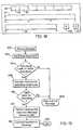
- FIG. 18illustrates an alternative data entry display for the handheld interface
- FIG. 19illustrates the processing sequence of the command server to process and transmit message lists.
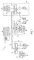
- FIG. 1illustrates a data retrieval/acquisition system according to the present invention generally illustrated by the reference numeral 1 .
- the instant system 1includes a master server 2 which communicates with multiple remote input units 4 through a communications bus 6 .
- Each input unit 4includes a communications server 12 directly connected to a command server 14 and data bases 16 .
- Each remote communications server 12interactively communicates with one or more handheld user interfaces 8 while located within a predefined region 5 proximate thereto. This interactive communication is conducted through a wireless dedicated communication channel, such as upon an infrared carrier signal.
- the communications server 12controls all interaction between the handheld interfaces 8 , the command servers 14 , and the communications bus 6 .
- the command servers 14control direct access to the databases 16 .
- the command servers 14may implement any conventionally known IO management system, such as Pro-Tree (version 2.0), SQL or Paradox.
- the communications server 12communicates with each handheld interface 8 through a unique communications protocol (hereafter referred to as the Handheld-Server Protocol).
- the communications server 12communicates with the command servers 14 through a unique protocol (hereafter referred to as the Message List Protocol).
- the communications server 12synchronizes its operations with those of the handheld interfaces 8 to minimize the excess data necessary for each transmission therebetween.
- the communications server 12 and interface 8also utilize shorthand code values to identify constantly transmitted information, such as commands, user IDs, database IDs, and the like.
- the instant systemis able to avoid the need to transmit the user ID, time, date, authorization code, and the like during every transmission.
- the userenters data at the handheld interface 8 , the data is transmitted to the communications server 12 and stored internally within the database 16 . Data may also be entered directly into the communications server 12 . Similarly, the user may request data previously submitted, in which case the communications server 12 accesses the corresponding database 16 , through the command server 14 , and transmits the necessary desired information to the requesting handheld interface 8 . Throughout operation, a backup copy may be maintained within the master server 2 for every remote database 16 . Additionally, the user may request, via the handheld interface 8 , data stored within a remote input unit 4 other than the data in the databases directly connected to the receiving communications server 12 .
- the corresponding communications server 12would accept the request from the handheld interface 8 , determine that the desired information is stored within a remote database and request such information through the communications bus 6 from the communications server 12 containing the corresponding database.
- the communications bus 6also allows data to be transmitted between communications servers 12 and between handheld interfaces 8 (such as when one doctor is requesting information from another doctor).
- the instant acquisition/retrieval system 1may be utilized within a healthcare facility wherein doctors, nurses, and staff utilize the handheld interfaces 8 to record and obtain patient information. These persons may be assigned different privileges which would allow varying levels of access to data.
- each communications servermay be located within a different ward or testing laboratory.
- a doctor in a general wardmay need to send a message to, or obtain information from, a doctor or nurse in radiology. To do so, the doctor would transmit a request through the handheld interface 8 , with the request being received and decoded in the general ward's communications server 12 .
- the source/receiving communications serverdetermines the appropriate destination communications server that corresponds to the destination handheld interface, into which the destination doctor or nurse has signed on.
- the desired messageis transmitted to the radiology server, and to the corresponding handheld interface which queries the user through audio, video, or vibrating means.
- the user within radiologymay transmit a response through the corresponding radiology and general ward communications servers 12 to the requesting doctor's handheld interface 8 .
- lab datamay be quickly transmitted to a surgeon during an operation.
- the instant acquisition/retrieval system 1also allows doctors, nurses, and staff members immediate access to clinical data, even after clinic hours are closed. To do so, the user merely enters a request through his/her handheld interface 8 , which is transmitted through the corresponding communications server 12 to the clinical communications server 12 . The necessary clinical data is obtained from the clinical database and returned along the communications bus 6 .
- the data acquisition/retrieval system 1 of the healthcare facilitymay be connected to similar systems via an ethernet connected between the master servers 2 .
- the handheld interfaces 8are used to enter all patient information such as personal information upon admittance, past medical histories, vital statistics throughout their stay in the hospital, and the like. For instance, these vital statistics may include systolic, diastolic, pulse, temperature, and respiratory information. Similarly, the handheld interface 8 may be used to enter information concerning the patient's fluid intake and output.
- the instant data acquisition/retrieval system 1also allows a user to carry a handheld interface 8 between regions (see the dashed line 5 in FIG. 1) dedicated to each communications server 12 .
- the handheld interface 23is considered to have signed off with the old communications server (as illustrated by the dashed line 22 ). Thereafter, the handheld interface 23 must be signed onto the new communications server (as illustrated by the line 24 ) before it may be used for data entry.
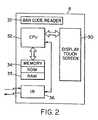
- FIG. 2generally illustrates a block diagram of a handheld interface 8 having a display screen 30 which may be back-illuminated and which is controlled by a CPU 32 to display desired information thereon.
- the display screen 30also functions as a touch pad and is sensitive to user contact. When contacted, the display screen 30 outputs a signal to the CPU 32 identifying the exact location of the contact therewith.
- the handheld interface 8further includes a memory module 34 which stores software to control processing of the CPU 32 and which temporarily stores data received from, and transmitted to, the corresponding communications server 12 .
- the CPU 32controls an IR interface 36 to control data transmissions to and from the communications server 12 .
- a bar code reader 37is included to allow the user to enter customer or product information from a bar code, such as customer/patient ID and the like.
- the handheld interface 8operates as an “event driven” device wherein the touch screen 30 is drawn to display a desired arrangement of virtual regions. Each region is assigned a unique identifier.
- the handheld interface 8recognizes each contact by a user as an event.
- the contact/eventis recognized with respect to the correspondingly defined region and the region identifier is returned. Thereafter, the CPU 32 identifies the necessary course of action based upon this identifier.
- the CPU 32may display a variety of menus, graphs, and the like upon the touch screen 30 .
- the CPU 32defines virtual regions which correspond to predefined processing sequences.
- the userinitiates a desired event sequence by contacting the preferred region corresponding to the event.
- the CPU 32provides multiple manners in which the user may enter and retrieve data.
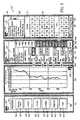
- FIG. 3 ( a )the CPU 32 draws a main menu 38 on the screen 30 and defines multiple menu selections 40 therein (see the flowchart of FIG. 10 ).
- Each menu selection 40overlays and corresponds to a virtual event region 42 corresponding to a different event/case. Every screen 30 is displayed with an escape key 43 which allows the user to escape back to a previous function/screen or back to the main menu.
- FIGS. 3 a - 3 dWhen implemented in a healthcare application, as illustrated in FIGS. 3 a - 3 d , when the user selects a vitals event region 44 , the CPU 32 recognizes it as such and processes a corresponding event sequence (see FIG. 13 ).
- the vitals input screen 60(also referred to as the data I/O screen) displays current patient information in the patient field 62 , such as the patient's name, social security number, status, and the date upon which the vitals were last updated.
- the vitals input screen 60illustrates the last current vitals (data sets) as shown in the systolic field 46 , diastolic field 48 , pulse field 50 , temperature field 52 , and respiratory field 54 (collectively referred to as data fields).
- the touch screen 30allows the user to activate a desired vital sign field by selecting a corresponding icon 46 , 48 , 50 , 52 , and 54 , respectively. Located immediately above each icon is the current value for the corresponding vitals field.
- This current valueis also displayed within three rolling keys along side of the icon (the rolling keys are designated by the reference numeral 56 ).
- the patient's systolic vital sign fieldis active in FIG. 3 c , as evidenced by the inverted rolling keys 56 .
- Proximate the rolling keys 56is a scroll bar 58 for illustrating in a bar format the current value of the active vital sign field (i.e., systolic) which is inverted to the current level ( 130 ).
- the usermay do so in multiple ways.
- the usermay update the patient's systolic vitals by consecutively contacting each rolling key 56 to be incremented. Each rolling key continuously increments, such as from 0 to 9 and then back to 0.
- the usermay enter patient vitals information by contacting the scroll bar 58 at the desired position.
- the scroll bar 58when the user contacts the scroll bar 58 , the bar is updated to reflect the newly entered value. If the user drags his/her finger along the scroll bar 58 , the CPU 32 will continuously update the level thereof to reflect this movement of the finger.
- the CPU 32updates the corresponding rolling keys 56 for the active field (i.e., the systolic field as illustrated in FIG. 3 ( c )).
- the usermay drag his/her finger across the scroll bar 58 until the desired value is displayed in the rolling keys 56 , at which time the user releases the scroll bar.
- the usermay activate a different vital sign field (i.e., change the mode) by selecting the corresponding icon ( 46 , 48 , 50 , 52 , and 54 ).
- the vitals input screen 60further includes change function keys 64 which afford the user's direct access to displays, graphs, screens and the transmit function. More specifically, the vitals input screen 60 allows the user direct access to the fluids input screen (not shown) for the current patient by pressing the fluids function button 66 . Alternatively, the user may view the selected vital sign field (e.g., systolic field) in a graph format by selecting the view graph button 68 .
- the vitals input screen 60further includes a transmit information button 70 which the user selects once a patient's new vital information has been entered. When the transmit button 70 has been pressed, the CPU 32 transmits the updated patient information to the communications server 12 in a format described below.
- FIG. 3 ( b )illustrates a graph corresponding to the present patient's systolic vitals which is displayed when the view graph button 68 is selected.
- FIG. 3 ( d )illustrates a patient inquiry screen 74 selected from the main menu 38 (also referred to as the data set inquiry screen).
- the patient inquiry screen 74displays a scrolling text window 78 which exhibits the currently selected patient's name (data set header) and those names alphabetically proximate thereto.
- a scrolling bar 80which includes an identifier 82 designating the position of the currently selected patient's name within a master alphabetical list.
- the usermay scroll through the patient list by contacting the scrolling bar 80 at a desired location therealong.
- the top and bottom of the scrolling bar 80corresponds to the beginning and end, respectively, of the list of patient names stored within the handheld interface 8 .
- the patient inquiry screen 74also includes a virtual keypad 76 which allows the user to enter the name of a desired patient. As the user selects each letter of the desired patient's name, the CPU 34 automatically performs a search upon the entered letters and updates the scroll text window 78 correspondingly. As the user enters additional letters, the CPU 32 concatenates these letters to the end of the search string it uses and again updates the scrolling text window 78 .
- the patient inquiry screen 74also includes function buttons 64 along a bottom thereof to allow the user to automatically jump to an alternative screen.
- a scan button 77is included to allow the user to read bar code data from a patient's wrist band, such as patient ID.
- FIG. 18illustrates an alternative scroll bar implementation which may be used to allow the user to enter alphanumeric information.
- the CPU 32may control the display screen 30 to illustrate a display field 90 and one or more scroll bars 92 .
- the scroll bar 92may be defined such that one end corresponds to the letter A while the opposite end corresponds to the letter Z.
- the CPU 32would define multiple regions along the length of the scroll bar 92 , each region corresponding to one letter of the alphabet.
- a letter corresponding to the touched regionsis displayed in a first location 94 of the display field 90 .
- the letter displayed within the first location 94will vary corresponding to the currently selected region.
- the last identified regionis designated as the correct letter and entered in the first location 94 of the display.
- the CPU 32operates to display a corresponding letter in the second field location 96 of the display field 90 .
- the CPU 32may also draw a second scroll bar 98 upon the display screen 30 .
- the first end of the second scroll barwould represent a 0 while the second end of the scroll bar 98 would represent a 9.
- the userwould enter numerals in the display fields 90 in the same manner as discussed above with respect to letters.
- a single scroll barmay be provided for letters and numerals with function buttons 100 and 101 being used to assign letters or numerals to the scroll bar.
- FIG. 15illustrates the RAM section 35 of the memory within the handheld interface 8 .
- the RAM memory 35includes a patient information section 200 for storing a list of patient names (data set headers) and patient identifiers (data set identifiers) associated with the present user of the handheld interface 8 .
- the RAM memory 35also includes a working space 202 for storing all other information entered by the user and transmitted between the handheld interface 8 and the communications server 12 . Each time the CPU 32 transmits a request to the communications server 12 for patient information, the CPU 32 redefines the current data structure within the working space 102 to correspond to the expected format of the return data from the communications server 12 .
- the CPU 32when the CPU 32 requests patient vitals, it expects the returned data to include, in a preset order, the patient's social security number, date on which the patient vitals were last updated, and the most recent systolic, diastolic, pulse, temperature and respiratory values.
- the CPU 32sets up fields within the working space 202 for each of these values.
- the CPU 32parses through the returned packet and assigns bytes therefrom to the desired field in the working space 202 .
- the RAM 35further includes a temporary buffer for storing incoming and outgoing packets of information which are to be transmitted to and which are received from the communication server 12 .
- the CPU 32moves data from the RAM 35 into the temporary buffer 204 immediately before transmitting this information and adds a packet header 206 thereto.
- FIGS. 4-8illustrate the processing sequence by which the CPU 32 controls the main menu, vital sign patient/data set input screen and the patient information screen (FIGS. 3 a - 3 d ).
- the CPU 32loops through one of two primary case/event handling loops (FIG. 4 ).
- the first case/event loopoperates to draw the main menu (FIG. 3 a ) and to handle events chosen from the main menu.
- a corresponding event identifieris returned as the calling identifier.
- a return codeis set equal to this calling identifier and the return code is checked against a predefined value (0). If the return code is non-zero, processing flow enters the second primary loop to call the corresponding event handling function.
- the second primary loopcorresponds to processing in which a menu other than the main menu is displayed (FIGS. 3 b - 3 d ).
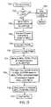
- FIG. 4generally illustrates the processing undergone by the handheld interface 8 when the user initiates the first session (i.e., when the user first logs in).
- the handheld unitprompts the user for the user's ID and password (step 1602 ).
- a packetis constructed in the temporary buffer 204 which contains a long header 206 structure and has a data section including the user ID and password (step 1604 ).
- This packetis transmitted (step 1606 ) and a validation code therefor is waited upon. If the validation code is not received (step 1608 ) processing returns to step 1602 in which the user is reprompted for the ID and password.
- step 1610a return code is set to indicate that processing should move to the patient inquiry module. Thereafter, the return code is tested to determine whether it equals zero (step 1623 ). If the return code equals zero, processing returns to step 1614 in which the main menu is redrawn.
- step 1616a main menu is drawn and key regions therein are defined in steps 1612 and 1614 , after which the system waits for an event to occur (step 1616 ). Once an event occurs, it is determined whether the event is within a defined menu regions 42 (step 1618 ) (i.e., whether the user has touched the display screen 30 at a location corresponding to a menu selection 40 ). If not, processing loops back to wait for the next event. If so, an event identifier is obtained for the key region in which the event occurred (step 1620 ). Next, an event handling function corresponding to the event identifier is called (step 1622 ).
- processingwaits for a call identifier returned from the called event handling function.
- a return codeis set equal to the call identifier (step 1623 ) and the return code is tested in step 1624 and if zero, processing returns to the initial step 1612 to redefine and redraw the main menu. If the return code does not equal zero, the process determines that the user has selected another function besides displaying the main menu. Thus, the event handling function corresponding to the non-zero return code is called (step 1626 ). Thereafter, the main event handling loop waits for the called function to return a call identifier which is tested in step 1624 .
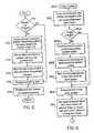
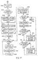
- FIGS. 5 and 6illustrate the process undergone when the patient information screen 74 is selected to be displayed (such as during the wake up function or when called by the user).
- an initialization routineis called in step 1700 (steps 1710 - 1720 in FIG. 6 ).
- This initializing processbegins by determining whether the handheld interface 8 includes a list of patient names (data set headers) and IDs (step 1710 ). If this list does not exist (such as when the handheld interface has initially been woken up), the unit constructs and transmits a packet to the communications server 12 requesting the patient list associated with the currently signed-in user (step 1712 ). The communications server 12 receives this packet, identifies the user ID, and requests the appropriate information from the command server 14 .
- the appropriate database 16is read and the patient list for the user is transmitted back to the handheld interface 8 .
- the interface 8sets up the data structure in the patient memory 200 for the patient list (step 1714 ), it waits for the returned patient list (step 1716 ). Once the patient list (name and ID) is received, it is stored in the patient memory 200 .
- the handheld interface 8may not include sufficient display space in the scrolling text window 78 to show an entire patient's name.
- the patient memory section 200will only include sufficient memory to store the maximum number of characters which may be displayed for a single patient name upon the screen.
- the patient screen formatis displayed (step 1718 ) as illustrated in FIG. 3 d .
- the patient namesare displayed in the scrolling text window 78 (step 1720 ) (FIG. 3 d ).
- a default portion thereofis displayed.
- the systemwaits for an event (step 1722 , in FIG. 6) and when one occurs, an event identifier is assigned thereto.
- the event identifieris passed to a case/event statement which includes every possible valid value for the event identifier.
- processingwill continue along one of six possible processing paths to blocks 1724 , 1726 , 1728 , 1730 , 1750 or 1756 , depending upon which event occurred.
- event 1724occurs (i.e., the user presses. the escape icon)
- the systemreturns a zero calling identifier to the main loop (thereby indicating that no new event handling function has been selected). If the event indicates that the user has touched the scrolling bar 80 , processing flows to box 1726 in which the system determines the exact location of the event (step 1732 ).
- This locationis correlated with a pointer that is used as an index into the patient list to identify the new patient to be displayed in the scrolling text window 78 .
- the pointer into the patient listis updated and the scrolling text window 78 is redrawn to display the name of the selected patient and a limited number of patient names surrounding the selected name (step 1734 ).
- the scrolling bar 80is updated to move the identifier 82 to a new position identifying the relative location of the indexed patient within the overall patient list (step 1736 ).
- the identifier 82is redrawn at the top of the scrolling bar 80 , and if the last patient is selected, the identifier 82 is drawn at the bottom of the scrolling bar 80 .
- the eventis identified as occurring within the scrolling text window 78 .
- processingflows to step 1728 .
- the location of the eventis again identified (step 1738 ) relative to the names currently displayed.
- the name closest to the eventis identified as the selected patient.
- the pointer into the patient listis updated to index the newly selected patient name (step 1740 ).
- This nameis displayed in the center of the scrolling text window and, optionally, may be inverted in color (step 1740 ).
- the identifier 82 within the scrolling bar 80is also redrawn to properly identify the new position of the selected patient within the patient list (step 1740 ).
- This selected letteris added to a temporary patient searching string within the work space memory 102 (step 1744 ).
- This letteris added to a search string (which is empty until the first letter is selected).
- the processorconducts a search based- upon the search string into the patient list to identify the name most closely corresponding to the letter(s) selected from the virtual keypad 76 (step 1746 ).
- a search stringexists (i.e., the user has already entered some letters) the newly selected letter is concatenated onto the search string and a new search is conducted upon the text strings within the patient list to find the first text string which is greater in alphabetic value than (i.e., closest to) the search string.
- the pointeris set to the closest patient name and the scrolling text window 78 and the scrolling bar 80 are updated (steps 1746 and 1748 ). If the user wishes to delete a letter from the search string, he/she simply pressing the delete region key.
- processing flowmoves to block 1750 .
- the bar code scanneris read to obtain the bar code scanned by the user (step 1752 ) (this bar code may appear on a patient's wrist band and the like).
- the bar codeincludes the patient ID, which is used to find the patient name within the patient list (step 1754 ).
- the pointer into the patient listis updated (step 1756 ) and the scrolling text window 78 and scrolling bar 80 are redrawn (step 1758 ).
- the usermay escape from the patient inquiry screen by pressing the escape icon 43 in the upper left corner or by selecting one of the function 64 buttons at the bottom of the screen (step 1760 ). As illustrated in FIG. 3 d , the user may escape to the main menu, review a patient's information complete record or review the patient's vitals. If the user presses one of the change function buttons 64 at the bottom of the screen, the corresponding event identifier is evaluated to determine which function key the user has selected (step 1762 ) and the corresponding return code is returned to the main processing loop in FIG. 16 (step 1764 ).
- FIGS. 7 a , 7 b and 8illustrate the processing sequence undergone by the handheld interface 8 when the vitals/data input/output handling function is chosen (i.e., when a user desires to enter patient vitals).
- the display screenis cleared (step 1800 ) and the vitals (data I/O) format is drawn upon the screen (step 1802 ).
- the key regionsare defined which correspond to each even identifier.
- it is determined whether the workspace memory contains vitals for a selected patientstep 1804 ). If not, the processor constructs and transmits a packet (step 1806 ) requesting patient vitals. Thereafter, the workspace memory 202 is set up in the data structure corresponding to patient vitals (step 1808 ).
- the handheld interfacewaits for the returned patient vitals, receives these vitals in one or more packets and disassembles the packets and stores the patient vitals in the workspace (step 1810 ).
- the processordraws the patient vitals onto the screen (step 1812 ) and sets the default mode to a predetermined field (e.g., systolic field).
- the vitals for the default fieldare drawn into the scroll bar (step 1814 ) and the default rolling keys 56 corresponding to the default field are inverted.
- the handheld interfacewaits for an event to occur (step 1816 in FIG. 7 a ) and when it occurs, identifies the event number corresponding thereto.
- the event numberis identified as corresponding to a rolling key 56 , it is determined whether the touched rolling keys are active (step 1819 ). If not active, processing returns to step 1816 . If active, a pointer is determined which identifies the field within the workspace memory 202 which corresponds to the specific roll key/vital sign selected (step 1820 ).
- the data value identified by the pointer into the workspaceis incremented by a 1, 10, 100, etc. depending upon the rolling key which was touched (step 1822 ).
- the systolic data value within the workspace memorywill be incremented by 10.
- the processorwill increment the diastolic data value within the workspace memory by 100.
- the processorwill update the pulse value within the workspace memory to “80”. Thereafter, the new vital sign is drawn into the rolling keys 56 which have been updated and the new vital sign is stored in the corresponding field in the workspace memory (step 1824 ). Finally, the processor updates the scroll bar 58 to reflect the change in the current data value (step 1826 ).
- step 1830processing proceeds to step 1830 .
- the rolling keysare deactivated for the previously active vital sign field (step 1832 ) and the rolling keys for the newly chosen vital sign are activated (step 1834 ).
- the rolling keys for the deactivated and newly activated vital sign fieldsare inverted to display the newly active field to the user (step 1836 ).
- the scroll bar 80is redrawn with parameters, ranges and current vital signs corresponding to the newly selected vital sign field (step 1838 ).
- step 1840When the identified event corresponds to touching the scroll bar 80 , process flows to step 1840 . Once the scroll bar is touched, the exact location of the event is determined therein and used to identify the corresponding vital sign value (step 1842 ). Then, a pointer is determined which identifies the vital sign data value within the workspace memory which corresponds to the active vital sign field (step 1844 ). This vital sign data value is updated to the new vital sign value selected within the scroll bar (step 1846 ). Thereafter, the active scroll keys are updated with the new data value (step 1848 ) and the scroll bar is inverted to reflect the new data value (step 1850 ). When the event occurs within the patient information region, processing flows to step 1852 . In such a case, the patient information screen is redrawn. To do so, a calling identifier is set to correspond to the patient information screen (step 1854 ) and control is returned to the main loop (step 1856 ).
- a pop-up windowmay appear and query the user as to whether it is desirable to go to the patient information screen or enter a patient identifier through the bar code reader. In either case, if the user touches the patient information region, before new patient vital signs have been transmitted to the communication server, the user is prompted as to whether or not these vital signs should be transmitted.
- the escape iconis touched, processing flows to step 1858 , after which the calling identifier is set to zero (step 1860 ). Processing is returned to the main loop (step 1862 ).
- step 1864processing flows then to step 1864 , after which the selected button is determined (step 1866 ).
- step 1867it is determined whether the event corresponds to the transmit button. If the selected button corresponds to the transmit button, the current patient vitals are constructed into a packet format and transmitted to the communication server 12 (step 1868 ). If the selected button does not correspond to the transmit button, the calling identifier is set equal to the newly selected screen (step 1870 ). Thereafter, control is returned to the main loop (step 1872 ).
- the processordetermines the active vital sign field (e.g., systolic field), and obtains the corresponding default parameters for the graph. Thereafter, the screen is cleared and a graph having the parameters for the active vital sign field is drawn. Next, the vital sign data values for the active vital sign field are read from the workspace memory and used to draw the graph.
- the active vital sign fielde.g., systolic field
- buttonsmay be displayed along the bottom thereof. These buttons would allow the user to automatically select another vital sign to view in a graph format without intermediately returning to the vital input screen.
- the handheld interface 8allows for user inputs and displays patient information to the user.
- FIG. 4illustrates the process by which the CPU 32 transmits data to the communications server 12 .
- each transmissioncomprises an information packet 300 of IR signals corresponding to a packet of data, wherein every packet is constructed with the same predetermined length (e.g., 128 bytes) and in one of two formats.
- This lengthis software and operative system definable and may vary.
- Certain messages transmitted between the handheld interfaces 8 and the corresponding communication servers 12comprise an amount of data which is unable to be assembled into a single packet.
- the transmitting devicesegments the data into a plurality of equal length packets 300 (referred to as frames).
- the series of framesform a message 302 .
- the first packet/first frame thereofis constructed with a header section 304 formed in a long header structure followed by a data field 306 .
- the long header 304includes a 4 byte command field 308 , a 6 byte user identifying field 310 , and a 4 byte message total field 312 .
- the command field 308identifies the process to be performed upon the subsequent data
- the user IDidentifies the user signed into the handheld interface 8 transmitting or receiving the packet 308
- the message total 312identifies the total length of the message which will follow. This total length includes all bytes within subsequent packets 300 corresponding to this specific message 302 .
- a data field 314(having 114 bytes in a packet with a 128 byte structure) follows.
- subsequent packets/framesare transmitted. These subsequent packets/frames are constructed with a short header structure 316 preceding the data segment 318 .
- the short header 316includes a 4 byte command 320 and a 4 byte positioning packet 322 identifying number to enable the receiving device to determine the position of the packet within the overall message.
- Packets containing a short header 316includes a 120 byte data field for a packet formed with 128 bytes.
- the first packet of each messageincludes a long header 304 structure followed by a data field, with each subsequent packet within the message including a short header 316 structure followed by a data field.
- the deviceis able to increase the amount of data transmitted within each packet for long messages.
- the transmitting deviceneed not send the user ID and the message total more than once for a given message since the receiving device is able to associate corresponding packets with a single message 302 based on the packet number 322 and communication channel.
- the CPU 32To transmit a message (FIG. 10 ), the CPU 32 reads the current data from the workspace memory 200 in the RAM 35 (step 400 ). Next, the CPU 32 determines the length of the message and the ID of the user signed in to that handheld interface 8 (step 402 ). The CPU 34 constructs a packet header formed with the long header structure (step 404 ). The CPU 34 clears the packet number (step 406 ) and writes the data to the transmit buffer (step 408 ). If the packet is full (step 410 ), the CPU 32 transmits the packet and clears the buffer (step 412 ). If the packet is not full, it determines if more data exists to write to the buffer (step 414 ). If no more data exists, it transmits the packet.
- step 416it is determined if more data exists, and if not it exits. If so, the packet number is incremented (step 418 ).
- the CPU 34constructs a partial short header for the second frame to be transmitted in this message (step 420 ).
- the partial headerincludes the code for the corresponding command and the current packet number.
- steps 410 through 420are repeated.
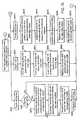
- FIG. 16illustrates a block diagram of the communication server 12 .
- the communication server 12includes an IR receiver/transmitter 100 which receives and transmits IR communication packets from and to the handheld interface 8 .
- the IR receiver transmitter 100operates in conjunction with an I/O card 102 to store a packet of information from each communication channel in the corresponding address within a temporary buffer 104 .
- Each communication channelcorresponds to a unique handheld interface 8 .
- the communication server 12may provide for 128 IR channels and thus, the temporary buffer 104 will include 128 buffer locations, with each buffer location having sufficient memory to store a complete IR packet 300 (FIG. 9 ).
- the number of channelsis locally definable and may be any desired number.
- the array locations within the temporary buffer 104store the IR packets in the format transmitted from the handheld interface 8 as described above.
- the communications server 12further includes an input buffer 108 which represents a storage space used by the CPU 106 when converting packets from the format stored in the temporary buffer 104 to message lists with a different format to be transmitted to the command servers 14 .
- the input buffer 108represents an array, each element of which includes the COM_INFO structure (explained below).
- Each element of the input buffer 108 arrayis accessed based on the device number. Thus, if 128 handheld interfaces 8 are being used, the input buffer 8 will include 128 elements.
- the communications server 12further includes a message buffer 110 which is utilized to store the actual data for each complete message sent from the hand held interface once all of the necessary packets have been transmitted by the handheld interface 8 and reassimilated by the CPU 106 into a single message.
- the COM_INFO stored in the input buffer 108includes a pointer MSG_From_HH into the message buffer to the beginning of the corresponding data string.
- the message listincludes a pointer to the corresponding data string in the message buffer 110 .
- Each message list received from the command server 14is initially stored in a transmit queue 116 prior to being converted back into packets 300 and transmitted to the handheld interface 8 .
- the message listincludes a pointer to a corresponding data string which is stored in the message buffer 110 when it is received from the command server 14 .
- the process and transmit queuesare operated in a first-in-first-out sequence such that each message is processed or transmitted in the order in which it is placed in the queue.
- the transmit and process queues 112 and 114constitute dynamic queuing systems which attach message lists in a linked list structure. Each message list includes the data structure illustrated below:
- the message list data structureincludes a first section COM_INFO dedicated to, and containing information concerning, messages received from the handheld interface 8 .
- the next four fieldsrepresent fields which are created immediately before transmitting a message list to the command server 14 and another communications servers 12 .
- the final field(Previous MSG_LST) is used as a pointer to the subsequent message list within the queue to be processed.
- the first section COM_INFOincludes a device number uniquely identifying the handheld interface transmitting the message. The device number is generated by the I/O card 102 when the CPU 32 requests a packet 300 from the temporary buffer 104 . The device number is produced depending upon the communications channel being accessed.
- the commandincludes the structure of the CMD field transmitted in the header of each packet 300 (i.e., the 2 byte database ID, 1 byte command ID, and 1 byte reserved).
- the commandrepresents the command to be processed in accordance with the corresponding message being transmitted to or from the handheld interface 8 .
- the 4 bytes within the commandare separated such that the first two bytes identify the database to be processed when performing the command, the third byte stores a number corresponding to the specific command to be performed, and the fourth byte is reserved.
- numerals 1 - 127represent commands to be processed by the command server, while numerals 128 - 255 represent a command from the handheld interface 8 .
- the use of shorthand code numbers for specific commandsreduces the amount of data to be transmitted to and from the handheld interface 8 .
- the Packet Numberis a long integer which is incremented each time a packet is appended to a message on the input buffer 108 .
- the User_ID_Tois a 6 byte value added by the handheld interface 8 to identify a destination user. If set to zero, the destination is the communications server. The communications and command servers determine which server to send the command to. This value if non-zero will identify the user of a handheld interface 8 desiring to communicate therewith.
- the User_ID_Fromis a 6 byte value added once at login time. This user ID is assigned to the channel to identify who is logged in at that channel. This value is maintained until the person signs out. Thus, the user ID will only be transmitted once during a login session.
- the communications server 12keeps track of each User ID signed onto handheld interfaces served by that communications server 12 .
- the message total length(MSG_Total) is a value assigned by the handheld interface 8 or by the command server 14 when a message is transmitted.
- the message length(MSG_LEN) is a value updated by the short and long header parsing functions to keep track of the length of a message in the message buffer 110 as the packets for the message are added thereto.
- the message length fieldis initially tested by the communications server 12 when processing each packet in the temporary buffer 104 to determine if the packet is in a long or short header form.
- the message pointer field(MSG_From_HH) is a pointer into the message buffer to the location of the actual data message. The MSG_From_HH pointer is updated each time a new packet is appended to a message.
- the message list structureincludes the above COM_INFO structure as an addition to a Data_File field that represents an integer identifying the database, written from the COM_INFO structure, to be processed in connection with the corresponding command.
- the command (CMD) fieldrepresents a one byte command, written from the COM_INFO structure, to be processed.
- the MSG_To_HH fieldrepresents a message pointer used to point to the data compiled by the command server in connection with this message which will ultimately be sent to the handheld interface 8 .
- the MSG_LEN fieldrepresents a long integer identifying the current length of the data corresponding to the message and stored in the message buffer.
- the Previous_MSG_LSTrepresents a pointer pointing to the next message to be processed. The previous message pointer enables the system to accomplish dynamic queuing for the process and transmit queues.
- FIG. 11illustrates the processing sequence by which the communication server 12 receives messages from the handheld interface 8 , processes these messages and transmits these messages to the command server 14 .
- the I/O card 102is initialized, along with the communication channels, buffers and queues (step 700 ).
- the data structures for the message list, COM_INFO, CMD, and short and long headersare set up (step 702 ).
- a current channel to be read by the I/O card 102is initialized to the first channel (step 704 ).
- the current channelis tested to determine whether data is being transmitted thereon from the corresponding handheld interface 8 (step 706 ). If data is present, the packet of transmitted data is read and stored in the temporary buffer 104 (step 708 ). The packet of data is stored within the temporary buffer 104 at the array address corresponding to the current channel.
- a channel identifying number corresponding to the transmitting handheld interface 8is also assigned thereto by the I/O card 102 .
- a check sum field within the-data packetis tested to determine whether the transmitted data is valid (step 710 ). If the data is invalid, the communication server takes the necessary corrective actions (step 712 ). If the data is valid, the CPU 106 requests the channel number (step 714 ) and the packet 300 from the I/O card 102 and utilizes the channel number to index the correct corresponding element within the input buffer 108 . Next, it is determined whether a packet is an initial frame or a subsequent frame of a message (step 716 ). To effect this test, the message total field, within the element of the input buffer 108 corresponding to the current channel, is read and compared to zero.
- the packet being readis identified as an initial packet which will include the long header structure. Otherwise, the packet is identified as one containing the short header structure. In either case, the packet number is incremented within the currently indexed element of the input buffer 108 .
- step 718If the packet contains the long header structure, processing moves to step 718 in which the parse long header function is invoked. If the packet includes the short header structure, processing moves to step 720 where the parse short header function is invoked.
- FIG. 12 and FIG. 13illustrate the parse long and short header functions.
- the first four bytes of the data packet within the temporary queueis read as the command (step 722 ). This command is compared with a list of valid commands and if the command is invalid the processor takes the necessary corrective action (step 724 ). If the command is valid, the command is written to the command field within the element of the input buffer 108 indexed by the corresponding channel number (step 726 ).
- the subsequent six bytes of the packet within the temp bufferis read as the User ID, if present, of the destination user for the attached message/data. This six byte ID is stored in the UserID_To field of the element within the input buffer 108 indexed by the current channel number (step 728 ). The User ID, corresponding to the signed on user, is added to the UserID_From field of the indexed element.
- the subsequent four bytesare read from the packet within the temporary buffer 104 as the total length of the following message (e.g., the total number of bytes to follow within one or more packets corresponding to the present message) (step 730 ).
- the four byte value representing the message totalis converted to a long integer (step 732 ) and assigned to the message total field within the element of the input buffer 108 indexed by the current channel number (step 734 ).
- the data section within the packetis written to the message buffer as a data string and the length thereof is stored within the message length field within the presently indexed element of the input buffer 108 (step 736 ).
- a message pointer pointing to the data string within the message buffer 110is stored within the message pointer field of the indexed element within the input buffer 108 (step 738 ). Finally, the element of the temporary buffer 110 is cleared (step 740 ). In this manner, steps 718 - 740 parse through a packet having a long header structure, create the COM_INFO structure within the input buffer 8 and store the message 302 from the handheld interface 8 within the message buffer 110 .
- step 716if in step 716 it is determined that the packet is not an initial packet, then the short header function is invoked (see FIG. 13 ). First, the first four bytes of the packet are pulled (step 742 ) and compared with the value in the command field of the currently indexed element within the input buffer 108 (this command is indexed based on the channel number) to determine if these commands are the same (step 744 ). If not, the system takes the necessary corrective actions (step 746 ). If the commands correspond, the packet number within the short header is pulled (step 746 ), converted to a long integer (step 748 ) and compared to the packet number (plus one) within the indexed element of the input buffer 108 (step 750 ).
- packet numbersmust correspond to ensure that the received packet is the next packet to be added to the input buffer 108 . If the packet numbers correspond, the present packet is identified as part of the message corresponding to the presently indexed element within the input buffer 108 and processing flows to step 752 , else it returns. If the packet is not matched based on above criteria, then a corrective action is taken.
- the data within the temporary buffer 110is pulled (step 752 ) and the portion of the message already stored in the message buffer 110 is read (step 754 ).
- the new datais added to the end of the stored message and the new total string is rewritten to the message buffer 110 (step 756 ).
- the message pointer (MSG_From_HH) and the message length (MSG_LEN)are updated within the corresponding fields of the COM_INFO of the indexed element of the input buffer 108 (step 758 ). Thereafter, the control returns to the main process (step 760 ).
- controlis returned to the main program, the current channel is incremented (step 760 ).
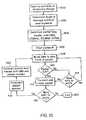
- processingmoves to the processing queue sequence (FIG. 14) to move completed messages 302 to the processing queue 112 .
- the current element pointer into the input buffer 108is set to the first input buffer element (step 800 ). Then, it compares the message total length (MSG_Total) with the message length (MSG_LEN) to determine whether a complete message corresponding to the current element within the input buffer 108 has been received and stored in the message buffer (step 802 ). If not, the incomplete message remains on the input buffer 108 and the current element pointer is incremented (step 804 ) and the process returns to step 802 .
- MSG_Totalmessage total length
- MSG_LENmessage length
- the messageis placed on the processing queue (step 806 ) by creating a message list therefor.
- the command information (COM_INFO) of the current element of the input buffer 108is written to the processing queue 112 and stored in the command information (COM_INFO) section therefor.
- the command information (COM_INFO)As the corresponding message represents a transmission from the handheld interface 8 to the command server 14 , the next four fields of the indexed message list element in the processing queue remain undefined.
- This message listis “pushed onto the back” of the processing queue by storing, in the preceding message list in the processing queue, a pointer to the current message list. This pointer is stored in the final field (Previous_MSG_LST) within the previous, most recent message list added to the processing queue (step 806 ).
- the corresponding element of the input buffer 108is cleared (step 808 ). Thereafter, the current element pointer into the input buffer 108 is incremented (step 810 ) and it is determined whether or not every element of the input buffer 108 has been tested (step 812 ). If not, processing returns to step 802 and the next element within the input buffer 108 is processed. If processing is done on the input buffer 108 , control moves to process the message lists on the processing queue.
- the first element of the processing queueis tested to determine whether a command is stored therein (steps 900 and 902 ). If a command exists on the processing queue, this command is “dequeued” (step 904 ) by reading the message information from the processing queue (which is stored in the message list structure).
- the command field (CMD) within the COM_INFO section of the message listis read.
- the messageis parsed into specific components (step 906 ), by reading the first two bytes of the command field, converting these bytes to a long integer form and storing the data base identifier in the Data_File field of the message list (step 908 ).
- the third byte of the command (CMD) field in the COM_INFO structureis read and stored in the Command field of the message list (step 910 ). Then the actual data message is appended to the message list structure based on the message pointer (MSG_TO_HH) and the message length (MSG_LEN) are reset (step 912 ).
- the communications server 12sends the message to the appropriate command server 14 based upon the database and command code (step 912 ).
- Previous_MSG_LSTPrevious message pointer
- Step 914the previous message pointer
- controlis returned to step 902 .
- each message upon the processing queue 112is parsed through and transmitted to the appropriate command server 14 .
- controlis moved to the create transmit queue module (step 916 ) (FIG. 15 ).
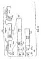
- FIG. 17illustrates the process by which the communication server 12 processes messages upon the transmit queue which are to be sent to the handheld interface 8 .
- the first message upon the transmit queueis tested (step 1000 ) to determine whether data is contained therein (step 1002 ). If data exists, the message is dequeued by taking the message off the transmit queue (step 1004 ).
- the command information from the message listis read and a long header constructed for the first packet to be transmitted to the handheld interface 8 for the message (steps 1008 and 1009 ).
- the data from the messageis written to the packet and transmitted (step 1010 and 1012 ). Thereafter, it is determined whether additional data remains to be transmitted to the handheld interface 8 (step 1014 ). If yes, a short header is constructed (step 1015 ) and additional data from the message is written to the packet containing the short header (step 1016 ).
- step 1018the packet containing the short header is transmitted (step 1018 ) and processing returns to step 1012 at which it is determined if more data remains. This loop is repeated until the entire message has been transformed from the message list structure into data packets and transmitted to the handheld interface 8 . Once the entire message has been transmitted, control passes to the next module (step 1020 ).
- the communications server 12tests the communication bus 6 and determines if messages have been sent from other communication servers. First, the communications bus is tested to see if a message exists (step 1100 ). If a message exists, the message is read (step 1104 ) and the command therefor is decoded (step 1106 ). Thereafter, the command is tested to determine whether the message should be transmitted to a corresponding handheld interface 8 or whether the message should be transmitted to a command server connected to the communication server 12 (steps 1108 and 1110 ). Thereafter, the message is placed on the transmit or processing queue depending upon the destination of the message (steps 1112 and 1114 ). Thereafter, control is returned to the main program (step 1116 ). This process is continuously repeated until the communication server 12 is turned off. Once turned off, the communications channels are closed and the system is turned off.
- the command serveroperates to update the corresponding databases based upon messages received from the communications server.
- the command serverutilizes a conventional software package for managing these databases, such as Pro-tree (version 2.0).
- Other database managing systemsmay be used to access the data base, such as DBase, CodeBase, B-Trieve, Cisam and the like.
- Particular commands within the conventional management systemare called depending upon the command code and database codes transmitted within the message list.
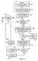
- FIG. 19illustrates the process by which the command server 14 invokes the database management functions.
- the command server 14receives a message (step 900 ), including the complete message list structure followed by the data message.
- the command server 14reads the data base file field (step 902 ) and determines whether that data base code is valid for the present command server 14 (step 904 ). If not, it returns an error message (step 906 ). If so, control is transferred to the database routine corresponding to the command code (CMD) in the Command field of the message list (step 908 ).
- CMDcommand code
- it is determined whether the command code is correct for the addressed databasestep 910 ). If not, it returns an error code (step 906 ).
- step 912accesses the message data within the message list and performs the appropriate operation upon the data base (step 912 ). Thereafter, it constructs a return message using the data returned from the database into the structure of the message list (step 914 ) and quits (step 916 ).
- command number 7may represent an add command, and thus, case “7” would direct the command server to read the data from the message and write this data to the next address within the database.
- command number within the messagemay represent a read or request operation, in response to which, the corresponding case would direct the command server to read the desired information from the database corresponding to the user ID transmitted within the message. The command server thereafter adds this data to the message and retransmits it to the communications server.
- scrolling text windowa key where scrolling text will reside.
- scrollera key associated with the scrolling text window, the scroller has a bar in it to indicate where the text within the text window is in relationship to the rest of the text.
- scrollbarthe tool used for entering vitals (darkened from the very bottom of the key to the value chosen by the user).
- rolling keya key with a digit in it, when the key is touched, that digit is incremented. If the digits value is 9 and it is incremented, it will contain the value 0 with no carry performed.
- init_scroll_barinit_scroll_bar—initializes all necessary variables and draws all of the detail.
- set_scroll_bar_valuethe user can set the value anytime.
- vital_inputcontains all the functions used to perform the vital input
- the Mode valueindicates what is being input at the moment, if the user has chosen systolic, then the systolic rolling keys are inverted and activated, and the scroll bar will have the systolic data in it.
- write_Keys_Datathis routine redraws the rolling keys associated with a certain mode, (example, if the mode is pulse and the user somehow changes the value, this routine draws the 100s value in the leftmost key, the 10s value in the middle key, and the 1s value in the rightmost key):
- ChangeModechanges the mode of the screen, this involves (1) turning off the old mode (example—pulse); (2) turning on the rolling keys of the new mode (example—systolic) so now an event may occur—also invert the keys so that they are white on black; and (3) calling Init_scroll_bar to redraw the scroll bar with the new modes details.
- make_graphreceiveives x, y values, x axis label, y axis label, the type of data that the x and y values are (time, short int, int, long int, float, etc.) and draws the graph, depending upon the type of data in x and y, it calls a simple routine that turns the x, y values into x, y plotting points on the screen.
- patinput.ccontains all of the functions used to pick a patient.
- DoPatientlnputdoes the entire screens functionality within this one routine.
- vital_ 1 .cthe starting point of the program contains all function calls.
- init_scrollerinitializes all necessary variables and draws of all the detail.
- get_scroll_text_valueupon an event in the scroll text window, this routine is called and it handles that event, then it returns the same value as does the get_scroller_value function.
- draw_scrollerDraws the bar inside of the scroller, then calls draw_scroll_text.
- draw_scroll-textdraws all of the text that appears in the scrolling text window.
- invert_picked_textinverts the text that is being pointed to by the user.
- open_irused to initial the IR communication with the AndroDat Card and setup the communication channels with each device.
- close_irused to close all communication channels with the hand held.
- init_com_infoused to reset and clear all data contained for one specified com)info buffer. This routine is called initially to initialize each buffer and ready to receive data. After a message has been received and put on the process queue, this routine is used to clear the old data and ready the input buffer for the next command.
- collect_messagesthis routine will read through each input channel to see if a message exists. If one exists, then the message will be read into a temporary buffer and passed to the routine place_message for placement on the input buffer.
- place_messagethis routine will determine if the message being read is the first or subsequent message. If the message is the first packet, then the routine parse_long_hdr is called. If the packet is the second or subsequent message, the routine parse short_hdr is called.
- parse_short_hdrthis routine is used to parse the structure tmp_buffer, validate the command being sent along with the correct packet number, then place the data in the appropriate in_buffer message structure. This routine is called after the initial command packet is sent.
- parse_long_hdrthis routine is used to parse the structure tmp-buffer, validate the command being sent. This routine then initializes the in_buffer structure and finally places the data in the in buffer messages structure. This routine is called when a handheld device sends its initial packet for requesting a command.
- this routineis the main routine which controls the logic flow of the entry communication server system.
- process_cmdthis routine is used to take the next message off the command queue then send it to the correct server for processing. This routine calls the dequeue function to physically dequeue the item off the command queue.
- process_transmitthis routine is used to take the next message off the transmit queue then send it to the correct server for processing. This routine calls the dequeue function to physically dequeue the item off the transmit queue.
- packet_msgthis routine is used to physically send the message from the communication server to the handheld computer via the AndroDat Card. It is responsible for all packets of the data and verify of successful transmission.
- this routinetakes completed messages and places them on the queue.
- a parameteris passed to which queue to place the message along with the data to queue.
- dequeuethis routine will take messages off the queue and place them in a temporary buffer to be processed by the communication server.
- a parameteris passed to which queue to process along with the temporary space to put message.
- nulqueuethis routine is used to initialize a queue and prepare it to start receiving data. Call to this routine will destroy any data existing in the queue.
- com_infothis structure is used to store the incoming message from the handheld
- in_bufferthis is an array of the structure com_info. This structure is used to hold the individual messages being received from the handheld computers.
- message_listthis structure is used to serve as the queuing functions for the command processing and data transmission.
- long_hdrthis is the structure of the header for initial communication to the server.
- short_hdrthis is the structure for second and subsequent communications of the second command.
Landscapes
- Engineering & Computer Science (AREA)
- Public Health (AREA)
- Epidemiology (AREA)
- General Health & Medical Sciences (AREA)
- Medical Informatics (AREA)
- Primary Health Care (AREA)
- Health & Medical Sciences (AREA)
- Theoretical Computer Science (AREA)
- Physics & Mathematics (AREA)
- General Engineering & Computer Science (AREA)
- General Physics & Mathematics (AREA)
- Measuring And Recording Apparatus For Diagnosis (AREA)
- User Interface Of Digital Computer (AREA)
- Mobile Radio Communication Systems (AREA)
Abstract
Description
| MESSAGE LIST |
| COM— | Data File | Com- | MSG_TO— | MSG_LEN | Prev |
| INFO | (Integer) | mand | HH | (Long | MSG_LST |
| 10 | (1) | (Pointer) | Integer) | (Pointer) | |
| COM_INFO |
| Device | CMD | Packet | User ID | User | MSG | MSG | MSG |
| Number | (4) | Number | To | ID | Total | Length | From |
| (Inte- | (Long | (6) | From | (Long | (Long | HH | |
| ger) | Integer) | (6) | Integer) | Integer) | (Pointer) | ||
Claims (25)
Priority Applications (1)
| Application Number | Priority Date | Filing Date | Title |
|---|---|---|---|
| US09/821,731US6571294B2 (en) | 1994-02-14 | 2001-03-29 | Bar-code-driven data acquisition and management system |
Applications Claiming Priority (3)
| Application Number | Priority Date | Filing Date | Title |
|---|---|---|---|
| US08/196,452US5867688A (en) | 1994-02-14 | 1994-02-14 | Data acquisition and retrieval system with wireless handheld user interface |
| US09/241,214US6389477B1 (en) | 1994-02-14 | 1999-02-01 | Communication protocol for use with a data acquisition and retrieval system with handheld user interface |
| US09/821,731US6571294B2 (en) | 1994-02-14 | 2001-03-29 | Bar-code-driven data acquisition and management system |
Related Parent Applications (1)
| Application Number | Title | Priority Date | Filing Date |
|---|---|---|---|
| US09/241,214ContinuationUS6389477B1 (en) | 1994-02-14 | 1999-02-01 | Communication protocol for use with a data acquisition and retrieval system with handheld user interface |
Publications (2)
| Publication Number | Publication Date |
|---|---|
| US20020040406A1 US20020040406A1 (en) | 2002-04-04 |
| US6571294B2true US6571294B2 (en) | 2003-05-27 |
Family
ID=22725481
Family Applications (10)
| Application Number | Title | Priority Date | Filing Date |
|---|---|---|---|
| US08/196,452Expired - LifetimeUS5867688A (en) | 1994-02-14 | 1994-02-14 | Data acquisition and retrieval system with wireless handheld user interface |
| US09/241,214Expired - Fee RelatedUS6389477B1 (en) | 1994-02-14 | 1999-02-01 | Communication protocol for use with a data acquisition and retrieval system with handheld user interface |
| US09/821,759Expired - Fee RelatedUS6772201B2 (en) | 1994-02-14 | 2001-03-29 | Multi-tiered computing system having at least one portable computer with a touch sensitive display device and graphical user interface for touch input in communication with an input computer coupled to a database |
| US09/821,731Expired - Fee RelatedUS6571294B2 (en) | 1994-02-14 | 2001-03-29 | Bar-code-driven data acquisition and management system |
| US09/821,760Expired - Fee RelatedUS6820050B2 (en) | 1994-02-14 | 2001-03-29 | Event-driven graphical user interface for use in a touch-screen enabled handheld portable data terminal |
| US09/821,761AbandonedUS20020035637A1 (en) | 1994-02-14 | 2001-03-29 | Handheld portable data terminal having an integrated code reader for data entry and an event-driven touch-screen enabled graphical user interface |
| US09/821,747AbandonedUS20020036619A1 (en) | 1994-02-14 | 2001-03-29 | Portable wireless data terminal having an event-driven touch-screen enabled graphical user interface and operably coupled to a computer and database via a wireless communication channel |
| US09/823,326Expired - Fee RelatedUS6493747B2 (en) | 1994-02-14 | 2001-03-30 | Multi-tier data acquisition and management system comprising at least one touch-screen enabled portable computing device operably coupled to computers via wireless communication for accessing data records stored in local databases coupled to the computers |
| US09/823,247Expired - Fee RelatedUS6507868B2 (en) | 1994-02-14 | 2001-03-30 | Bar code driven data communication network |
| US10/084,242AbandonedUS20020184384A1 (en) | 1994-02-14 | 2002-02-27 | Communication protocol for use with a data acquisition and retrieval system with handheld user interface |
Family Applications Before (3)
| Application Number | Title | Priority Date | Filing Date |
|---|---|---|---|
| US08/196,452Expired - LifetimeUS5867688A (en) | 1994-02-14 | 1994-02-14 | Data acquisition and retrieval system with wireless handheld user interface |
| US09/241,214Expired - Fee RelatedUS6389477B1 (en) | 1994-02-14 | 1999-02-01 | Communication protocol for use with a data acquisition and retrieval system with handheld user interface |
| US09/821,759Expired - Fee RelatedUS6772201B2 (en) | 1994-02-14 | 2001-03-29 | Multi-tiered computing system having at least one portable computer with a touch sensitive display device and graphical user interface for touch input in communication with an input computer coupled to a database |
Family Applications After (6)
| Application Number | Title | Priority Date | Filing Date |
|---|---|---|---|
| US09/821,760Expired - Fee RelatedUS6820050B2 (en) | 1994-02-14 | 2001-03-29 | Event-driven graphical user interface for use in a touch-screen enabled handheld portable data terminal |
| US09/821,761AbandonedUS20020035637A1 (en) | 1994-02-14 | 2001-03-29 | Handheld portable data terminal having an integrated code reader for data entry and an event-driven touch-screen enabled graphical user interface |
| US09/821,747AbandonedUS20020036619A1 (en) | 1994-02-14 | 2001-03-29 | Portable wireless data terminal having an event-driven touch-screen enabled graphical user interface and operably coupled to a computer and database via a wireless communication channel |
| US09/823,326Expired - Fee RelatedUS6493747B2 (en) | 1994-02-14 | 2001-03-30 | Multi-tier data acquisition and management system comprising at least one touch-screen enabled portable computing device operably coupled to computers via wireless communication for accessing data records stored in local databases coupled to the computers |
| US09/823,247Expired - Fee RelatedUS6507868B2 (en) | 1994-02-14 | 2001-03-30 | Bar code driven data communication network |
| US10/084,242AbandonedUS20020184384A1 (en) | 1994-02-14 | 2002-02-27 | Communication protocol for use with a data acquisition and retrieval system with handheld user interface |
Country Status (1)
| Country | Link |
|---|---|
| US (10) | US5867688A (en) |
Cited By (37)
| Publication number | Priority date | Publication date | Assignee | Title |
|---|---|---|---|---|
| US20030023580A1 (en)* | 2001-04-03 | 2003-01-30 | Braud Kristopher P. | Method and system for assimilating data from ancillary preumbra systems onto an enterprise system |
| US6732933B2 (en)* | 2001-10-15 | 2004-05-11 | Symbol Technologies, Inc. | Coupling of bar code data readers to mobile terminals operable in wireless networks |
| US20070233050A1 (en)* | 2006-03-28 | 2007-10-04 | Hospira, Inc. | Medication administration and management system and method |
| CN100342703C (en)* | 2005-08-08 | 2007-10-10 | 珠海格力电器股份有限公司 | Electronic bar code recognition method |
| US7293030B2 (en)* | 2001-11-29 | 2007-11-06 | Symantec Operating Corporation | Methods, functional data, and systems to represent a storage environment |
| US20090021347A1 (en)* | 2007-07-18 | 2009-01-22 | U.S. Security Associates, Inc. | Systems and methods for monitoring and actuating a vehicle gate |
| WO2012104879A1 (en)* | 2011-02-02 | 2012-08-09 | Trizero S.R.L. | Method and system for management of data in electronic format |
| US8251904B2 (en) | 2005-06-09 | 2012-08-28 | Roche Diagnostics Operations, Inc. | Device and method for insulin dosing |
| US9407665B2 (en) | 2014-10-07 | 2016-08-02 | Demandware Inc. | Contract broker for secure ad-hoc personal data sharing |
| US20170185732A1 (en)* | 2015-12-29 | 2017-06-29 | Ethicon Endo-Surgery, Inc. | Patient monitoring system with network of treatment equipment |
| US9727693B2 (en) | 2015-07-20 | 2017-08-08 | General Electric Company | Automated tracking of a medical procedure using macros |
| US9971871B2 (en) | 2011-10-21 | 2018-05-15 | Icu Medical, Inc. | Medical device update system |
| US10042986B2 (en) | 2013-11-19 | 2018-08-07 | Icu Medical, Inc. | Infusion pump automation system and method |
| US10238801B2 (en) | 2009-04-17 | 2019-03-26 | Icu Medical, Inc. | System and method for configuring a rule set for medical event management and responses |
| US10242060B2 (en) | 2006-10-16 | 2019-03-26 | Icu Medical, Inc. | System and method for comparing and utilizing activity information and configuration information from multiple medical device management systems |
| US10238799B2 (en) | 2014-09-15 | 2019-03-26 | Icu Medical, Inc. | Matching delayed infusion auto-programs with manually entered infusion programs |
| US10311972B2 (en) | 2013-11-11 | 2019-06-04 | Icu Medical, Inc. | Medical device system performance index |
| US10314974B2 (en) | 2014-06-16 | 2019-06-11 | Icu Medical, Inc. | System for monitoring and delivering medication to a patient and method of using the same to minimize the risks associated with automated therapy |
| US10333843B2 (en) | 2013-03-06 | 2019-06-25 | Icu Medical, Inc. | Medical device communication method |
| US10434246B2 (en) | 2003-10-07 | 2019-10-08 | Icu Medical, Inc. | Medication management system |
| US10692595B2 (en) | 2018-07-26 | 2020-06-23 | Icu Medical, Inc. | Drug library dynamic version management |
| US10741280B2 (en) | 2018-07-17 | 2020-08-11 | Icu Medical, Inc. | Tagging pump messages with identifiers that facilitate restructuring |
| US10765799B2 (en) | 2013-09-20 | 2020-09-08 | Icu Medical, Inc. | Fail-safe drug infusion therapy system |
| US10861592B2 (en) | 2018-07-17 | 2020-12-08 | Icu Medical, Inc. | Reducing infusion pump network congestion by staggering updates |
| US10898641B2 (en) | 2014-04-30 | 2021-01-26 | Icu Medical, Inc. | Patient care system with conditional alarm forwarding |
| US20220018666A1 (en)* | 2016-12-22 | 2022-01-20 | Nissan North America, Inc. | Autonomous vehicle service system |
| US11235100B2 (en) | 2003-11-13 | 2022-02-01 | Icu Medical, Inc. | System for maintaining drug information and communicating with medication delivery devices |
| US11294407B2 (en) | 2001-04-27 | 2022-04-05 | Roche Diabetes Care, Inc. | Device and method for insulin dosing |
| US11309070B2 (en) | 2018-07-26 | 2022-04-19 | Icu Medical, Inc. | Drug library manager with customized worksheets |
| US11328805B2 (en) | 2018-07-17 | 2022-05-10 | Icu Medical, Inc. | Reducing infusion pump network congestion by staggering updates |
| US11571508B2 (en) | 2013-08-30 | 2023-02-07 | Icu Medical, Inc. | System and method of monitoring and managing a remote infusion regimen |
| US11574737B2 (en) | 2016-07-14 | 2023-02-07 | Icu Medical, Inc. | Multi-communication path selection and security system for a medical device |
| US11587669B2 (en) | 2018-07-17 | 2023-02-21 | Icu Medical, Inc. | Passing authentication token to authorize access to rest calls via web sockets |
| US11605468B2 (en) | 2015-05-26 | 2023-03-14 | Icu Medical, Inc. | Infusion pump system and method with multiple drug library editor source capability |
| US12130910B2 (en) | 2019-05-08 | 2024-10-29 | Icu Medical, Inc. | Threshold signature based medical device management |
| US12303464B2 (en) | 2020-04-03 | 2025-05-20 | Icu Medical, Inc. | Systems, methods, and components for transferring medical fluids |
| US12431238B2 (en) | 2020-09-05 | 2025-09-30 | Icu Medical, Inc. | Identity-based secure medical device communications |
Families Citing this family (282)
| Publication number | Priority date | Publication date | Assignee | Title |
|---|---|---|---|---|
| US9286294B2 (en) | 1992-12-09 | 2016-03-15 | Comcast Ip Holdings I, Llc | Video and digital multimedia aggregator content suggestion engine |
| US7168084B1 (en) | 1992-12-09 | 2007-01-23 | Sedna Patent Services, Llc | Method and apparatus for targeting virtual objects |
| US5867688A (en)* | 1994-02-14 | 1999-02-02 | Reliable Transaction Processing, Inc. | Data acquisition and retrieval system with wireless handheld user interface |
| US6292181B1 (en)* | 1994-09-02 | 2001-09-18 | Nec Corporation | Structure and method for controlling a host computer using a remote hand-held interface device |
| US5818438A (en)* | 1995-04-25 | 1998-10-06 | Bellsouth Corporation | System and method for providing television services |
| US7054271B2 (en) | 1996-12-06 | 2006-05-30 | Ipco, Llc | Wireless network system and method for providing same |
| US8982856B2 (en) | 1996-12-06 | 2015-03-17 | Ipco, Llc | Systems and methods for facilitating wireless network communication, satellite-based wireless network systems, and aircraft-based wireless network systems, and related methods |
| US6233327B1 (en)* | 1997-02-14 | 2001-05-15 | Statsignal Systems, Inc. | Multi-function general purpose transceiver |
| US6253228B1 (en)* | 1997-03-31 | 2001-06-26 | Apple Computer, Inc. | Method and apparatus for updating and synchronizing information between a client and a server |
| US6073141A (en)* | 1997-11-25 | 2000-06-06 | International Business Machine Corporation | System and method for synchronizing local versions of database |
| US6065120A (en) | 1997-12-09 | 2000-05-16 | Phone.Com, Inc. | Method and system for self-provisioning a rendezvous to ensure secure access to information in a database from multiple devices |
| US6105016A (en)* | 1998-03-06 | 2000-08-15 | Jodfrey Associates, Inc. | Data acquisition system |
| US7181501B2 (en)* | 1998-03-19 | 2007-02-20 | Isochron, Inc. | Remote data acquisition, transmission and analysis system including handheld wireless equipment |
| US7167892B2 (en)* | 1998-03-19 | 2007-01-23 | Isochron, Inc. | System, method and apparatus for vending machine wireless audit and cashless transaction transport |
| US20060161473A1 (en)* | 1998-03-19 | 2006-07-20 | Defosse Erin M | Remote data acquisition, transmission and analysis system including handheld wireless equipment |
| US7020680B2 (en)* | 1998-03-19 | 2006-03-28 | Isochron, Llc | System and method for monitoring and control of beverage dispensing equipment |
| US20070050465A1 (en)* | 1998-03-19 | 2007-03-01 | Canter James M | Packet capture agent for use in field assets employing shared bus architecture |
| US6457038B1 (en) | 1998-03-19 | 2002-09-24 | Isochron Data Corporation | Wide area network operation's center that sends and receives data from vending machines |
| US8631093B2 (en) | 1998-03-19 | 2014-01-14 | Crane Merchandising Systems, Inc. | Remote data acquisition, transmission and analysis system including handheld wireless equipment |
| US5996894A (en)* | 1998-03-24 | 1999-12-07 | Compeye Corporation | Virtual key pad for optical scanning apparatus |
| US6182220B1 (en)* | 1998-03-30 | 2001-01-30 | International Business Machines Corporation | System and method for building and exchanging encrypted passwords between a client and server |
| US6243738B1 (en)* | 1998-04-06 | 2001-06-05 | National Instruments Corporation | Data acquisition system which includes remote access to data acquisition devices |
| US6343318B1 (en) | 1998-05-29 | 2002-01-29 | Palm, Inc. | Method and apparatus for communicating information over low bandwidth communications networks |
| US7349557B2 (en)* | 1998-06-19 | 2008-03-25 | Solidus Networks, Inc. | Electronic transaction verification system |
| US8410931B2 (en) | 1998-06-22 | 2013-04-02 | Sipco, Llc | Mobile inventory unit monitoring systems and methods |
| US6914893B2 (en) | 1998-06-22 | 2005-07-05 | Statsignal Ipc, Llc | System and method for monitoring and controlling remote devices |
| US6437692B1 (en) | 1998-06-22 | 2002-08-20 | Statsignal Systems, Inc. | System and method for monitoring and controlling remote devices |
| US7110955B1 (en) | 1998-07-20 | 2006-09-19 | Patientkeeper, Inc. | Device for automating billing reimbursement |
| US7091968B1 (en)* | 1998-07-23 | 2006-08-15 | Sedna Patent Services, Llc | Method and apparatus for encoding a user interface |
| EP1097587A1 (en) | 1998-07-23 | 2001-05-09 | Diva Systems Corporation | Interactive user interface |
| US6754905B2 (en) | 1998-07-23 | 2004-06-22 | Diva Systems Corporation | Data structure and methods for providing an interactive program guide |
| US9924234B2 (en) | 1998-07-23 | 2018-03-20 | Comcast Ip Holdings I, Llc | Data structure and methods for providing an interactive program |
| US6324571B1 (en)* | 1998-09-21 | 2001-11-27 | Microsoft Corporation | Floating single master operation |
| JP2000165364A (en)* | 1998-11-30 | 2000-06-16 | Sony Corp | Radio network and method for time synchronization establishment among a plurality of buses |
| US6516327B1 (en)* | 1998-12-24 | 2003-02-04 | International Business Machines Corporation | System and method for synchronizing data in multiple databases |
| US7650425B2 (en) | 1999-03-18 | 2010-01-19 | Sipco, Llc | System and method for controlling communication between a host computer and communication devices associated with remote devices in an automated monitoring system |
| US6904610B1 (en) | 1999-04-15 | 2005-06-07 | Sedna Patent Services, Llc | Server-centric customized interactive program guide in an interactive television environment |
| US7096487B1 (en) | 1999-10-27 | 2006-08-22 | Sedna Patent Services, Llc | Apparatus and method for combining realtime and non-realtime encoded content |
| US6754271B1 (en) | 1999-04-15 | 2004-06-22 | Diva Systems Corporation | Temporal slice persistence method and apparatus for delivery of interactive program guide |
| JP4207323B2 (en)* | 1999-08-26 | 2009-01-14 | 富士通株式会社 | Data transfer apparatus and data transfer method |
| WO2001020476A1 (en)* | 1999-09-16 | 2001-03-22 | General Electric Company | A virtual modular relay device |
| DE60034364D1 (en) | 1999-10-27 | 2007-05-24 | Sedna Patent Services Llc | MULTIPLE VIDEO DRIVES USING SLICE BASED CODING |
| AU3269301A (en) | 1999-11-15 | 2001-05-30 | Lance A. Liotta | Real-time delivery of medical test data to portable communications devices |
| US6519569B1 (en)* | 1999-12-01 | 2003-02-11 | B. Braun Medical, Inc. | Security infusion pump with bar code reader |
| US7645258B2 (en) | 1999-12-01 | 2010-01-12 | B. Braun Medical, Inc. | Patient medication IV delivery pump with wireless communication to a hospital information management system |
| US6790198B1 (en) | 1999-12-01 | 2004-09-14 | B-Braun Medical, Inc. | Patient medication IV delivery pump with wireless communication to a hospital information management system |
| US20020059368A1 (en)* | 2000-01-07 | 2002-05-16 | Soneticom, Inc. | Wireless remote computer interface system |
| AU4322101A (en)* | 2000-02-28 | 2001-09-12 | Gregory Demopulos | Use of internet site as a registry for results of medical tests |
| US8577697B2 (en)* | 2000-02-28 | 2013-11-05 | Gregory A. Demopulos | Use of internet site as a registry for results of medical tests |
| US6707942B1 (en)* | 2000-03-01 | 2004-03-16 | Palm Source, Inc. | Method and apparatus for using pressure information for improved computer controlled handwriting recognition, data entry and user authentication |
| US7054443B1 (en)* | 2000-03-27 | 2006-05-30 | Microsoft Corporation | System and method for protecting digital goods using random and automatic code obfuscation |
| US7080257B1 (en) | 2000-03-27 | 2006-07-18 | Microsoft Corporation | Protecting digital goods using oblivious checking |
| US20010047426A1 (en)* | 2000-03-31 | 2001-11-29 | Hunter Kevin D. | Device-based routing for web content retrieval |
| EP1290652A2 (en) | 2000-05-05 | 2003-03-12 | Hill-Rom Services, Inc. | Hospital monitoring and control system and method |
| BR0110596A (en) | 2000-05-05 | 2005-08-02 | Hill Rom Services Inc | Patient monitoring system, computer system, patient information monitoring system, patient care device, walker device, patient care device, and computer display |
| US20030097474A1 (en)* | 2000-05-12 | 2003-05-22 | Isochron Data Corporation | Method and system for the efficient communication of data with and between remote computing devices |
| US7013337B2 (en)* | 2000-05-12 | 2006-03-14 | Isochron, Llc | Method and system for the optimal formatting, reduction and compression of DEX/UCS data |
| US10353856B2 (en) | 2011-03-17 | 2019-07-16 | Carefusion 303, Inc. | Scalable communication system |
| US7860583B2 (en) | 2004-08-25 | 2010-12-28 | Carefusion 303, Inc. | System and method for dynamically adjusting patient therapy |
| US11087873B2 (en) | 2000-05-18 | 2021-08-10 | Carefusion 303, Inc. | Context-aware healthcare notification system |
| US9600633B2 (en) | 2000-05-18 | 2017-03-21 | Carefusion 303, Inc. | Distributed remote asset and medication management drug delivery system |
| US9741001B2 (en) | 2000-05-18 | 2017-08-22 | Carefusion 303, Inc. | Predictive medication safety |
| US9427520B2 (en) | 2005-02-11 | 2016-08-30 | Carefusion 303, Inc. | Management of pending medication orders |
| US10062457B2 (en) | 2012-07-26 | 2018-08-28 | Carefusion 303, Inc. | Predictive notifications for adverse patient events |
| US7010594B2 (en)* | 2000-05-26 | 2006-03-07 | Isochron, Llc | System using environmental sensor and intelligent management and control transceiver for monitoring and controlling remote computing resources |
| FR2809901B1 (en)* | 2000-06-05 | 2002-11-22 | Sekoya | METHOD FOR TRANSMITTING A MESSAGE BETWEEN TWO CONNECTED COMPUTERS AND CORRESPONDING MESSAGING SYSTEMS |
| US6874037B1 (en) | 2000-06-19 | 2005-03-29 | Sony Corporation | Method and apparatus for synchronizing device information |
| US7216145B2 (en)* | 2000-06-23 | 2007-05-08 | Mission Communications, Llc | Event notification system |
| US8688474B2 (en)* | 2000-06-26 | 2014-04-01 | Epic Systems Corporation | Patient health record access system |
| US20020128872A1 (en)* | 2000-08-07 | 2002-09-12 | Giammattei Charles P. | Medical data recordation system |
| US7139564B2 (en) | 2000-08-08 | 2006-11-21 | Hebert Thomas H | Wireless communication device for field personnel |
| US6950994B2 (en)* | 2000-08-31 | 2005-09-27 | Yahoo! Inc. | Data list transmutation and input mapping |
| US7251610B2 (en)* | 2000-09-20 | 2007-07-31 | Epic Systems Corporation | Clinical documentation system for use by multiple caregivers |
| US8050944B2 (en)* | 2000-09-20 | 2011-11-01 | Epic Systems Corporation | Intelligent patient visit information management and navigation system |
| US7076275B1 (en)* | 2000-10-13 | 2006-07-11 | Palmsource, Inc. | Method and system for single-step enablement of telephony functionality for a portable computer system |
| WO2002033593A1 (en)* | 2000-10-16 | 2002-04-25 | Aether Systems, Inc. | Run-time engine implemented on a computing device allowing synchronization of records during application execution |
| US6804707B1 (en)* | 2000-10-20 | 2004-10-12 | Eric Ronning | Method and system for delivering wireless messages and information to personal computing devices |
| US6595430B1 (en)* | 2000-10-26 | 2003-07-22 | Honeywell International Inc. | Graphical user interface system for a thermal comfort controller |
| US7673241B2 (en)* | 2002-06-26 | 2010-03-02 | Siebel Systems, Inc. | User interface for multi-media communication for the visually disabled |
| US20020056075A1 (en)* | 2000-11-06 | 2002-05-09 | Andrew Hamilton | System for a run-time engine capable for pager capable remote device |
| US20020055939A1 (en)* | 2000-11-06 | 2002-05-09 | Joseph Nardone | System for a configurable open database connectivity conduit |
| US20020055918A1 (en)* | 2000-11-08 | 2002-05-09 | Patrick Hlathein | Operating room resource management system incorporating an interactive, visual method for coordinating multiple, interdependent |
| US6618683B1 (en) | 2000-12-12 | 2003-09-09 | International Business Machines Corporation | Method and apparatus for calibrating an accelerometer-based navigation system |
| US7275220B2 (en)* | 2000-12-22 | 2007-09-25 | Epic Systems Corporation | System and method for a seamless user interface for an integrated electronic health care information system |
| US6983423B2 (en)* | 2000-12-22 | 2006-01-03 | Epic Systems Corporation | Electronic system for collecting and communicating clinical order information in an acute care setting |
| US20020095487A1 (en)* | 2001-01-18 | 2002-07-18 | Robert Day | System for registering, locating, and identifying network equipment |
| US20020143582A1 (en)* | 2001-02-01 | 2002-10-03 | Neuman Sherry L. | System and method for creating prescriptions |
| US7831449B2 (en)* | 2001-02-02 | 2010-11-09 | Thompson Reuters (Healthcare) Inc. | Method and system for extracting medical information for presentation to medical providers on mobile terminals |
| US7505577B2 (en)* | 2001-03-31 | 2009-03-17 | Siebel Systems, Inc. | System and method for multi-channel communication queuing |
| US7581230B2 (en)* | 2001-02-06 | 2009-08-25 | Siebel Systems, Inc. | Adaptive communication application programming interface |
| US20030158755A1 (en)* | 2001-03-01 | 2003-08-21 | Neuman Sherry L. | System and method for conducting drug use evaluation |
| GB2372904B (en)* | 2001-03-02 | 2004-09-08 | Nokia Mobile Phones Ltd | Electronic transactions |
| US20020138636A1 (en)* | 2001-03-23 | 2002-09-26 | Mark Buttner | Method for automatically mass generating personalized data report outputs |
| US7363388B2 (en)* | 2001-03-28 | 2008-04-22 | Siebel Systems, Inc. | Method and system for direct server synchronization with a computing device |
| US6829655B1 (en) | 2001-03-28 | 2004-12-07 | Siebel Systems, Inc. | Method and system for server synchronization with a computing device via a companion device |
| EP1374194A2 (en) | 2001-03-30 | 2004-01-02 | Hill-Rom Services, Inc. | Hospital bed and network system |
| US7315616B2 (en)* | 2001-03-31 | 2008-01-01 | Siebel Systems, Inc. | System and method for maintaining real-time agent information for multi-channel communication queuing |
| US8601492B2 (en)* | 2001-03-31 | 2013-12-03 | Siebel Systems, Inc. | User interface for multi-channel communication |
| US7730204B2 (en)* | 2001-03-31 | 2010-06-01 | Siebel Systems, Inc. | Extensible interface for inter-module communication |
| US20030018705A1 (en)* | 2001-03-31 | 2003-01-23 | Mingte Chen | Media-independent communication server |
| US20030206192A1 (en)* | 2001-03-31 | 2003-11-06 | Mingte Chen | Asynchronous message push to web browser |
| US20070203797A1 (en)* | 2001-03-31 | 2007-08-30 | Annadata Anil K | Configurable media-independent server |
| US20020165898A1 (en)* | 2001-05-03 | 2002-11-07 | Joe Duffy | Recipient-determined method for sharing tasks in an advanced electronic messaging/workflow system |
| US6882239B2 (en)* | 2001-05-08 | 2005-04-19 | Formfactor, Inc. | Electromagnetically coupled interconnect system |
| US7272232B1 (en)* | 2001-05-30 | 2007-09-18 | Palmsource, Inc. | System and method for prioritizing and balancing simultaneous audio outputs in a handheld device |
| US7164884B2 (en)* | 2001-06-29 | 2007-01-16 | Isochron, Llc | Method and system for interfacing a machine controller and a wireless network |
| US7778600B2 (en)* | 2001-06-29 | 2010-08-17 | Crane Merchandising Systems, Inc. | Apparatus and method to provide multiple wireless communication paths to and from remotely located equipment |
| US7103171B1 (en)* | 2001-06-29 | 2006-09-05 | Siebel Systems, Inc. | System and method for multi-channel communication queuing using routing and escalation rules |
| US20020077801A1 (en)* | 2001-06-29 | 2002-06-20 | Superwings, Inc. | Facilited remote console and terminal emulator |
| US20030208382A1 (en)* | 2001-07-05 | 2003-11-06 | Westfall Mark D | Electronic medical record system and method |
| US6925335B2 (en)* | 2001-07-05 | 2005-08-02 | Isochron, Llc | Real-time alert mechanism for monitoring and controlling field assets via wireless and internet technologies |
| US7774307B2 (en)* | 2001-07-24 | 2010-08-10 | Siebel Systems, Inc. | Method and apparatus for synchronizing a database with a third party database |
| US20030061073A1 (en)* | 2001-08-01 | 2003-03-27 | Khiang Seow | Method and system for displaying patient information |
| US7793326B2 (en) | 2001-08-03 | 2010-09-07 | Comcast Ip Holdings I, Llc | Video and digital multimedia aggregator |
| US7908628B2 (en) | 2001-08-03 | 2011-03-15 | Comcast Ip Holdings I, Llc | Video and digital multimedia aggregator content coding and formatting |
| TW522326B (en)* | 2001-08-03 | 2003-03-01 | Inventec Corp | Real-time data customer service system and method thereof |
| US6658260B2 (en)* | 2001-09-05 | 2003-12-02 | Telecommunication Systems, Inc. | Inter-carrier short messaging service providing phone number only experience |
| US7761535B2 (en) | 2001-09-28 | 2010-07-20 | Siebel Systems, Inc. | Method and system for server synchronization with a computing device |
| US7526575B2 (en)* | 2001-09-28 | 2009-04-28 | Siebel Systems, Inc. | Method and system for client-based operations in server synchronization with a computing device |
| US7225260B2 (en)* | 2001-09-28 | 2007-05-29 | Symbol Technologies, Inc. | Software method for maintaining connectivity between applications during communications by mobile computer terminals operable in wireless networks |
| US7257649B2 (en)* | 2001-09-28 | 2007-08-14 | Siebel Systems, Inc. | Method and system for transferring information during server synchronization with a computing device |
| US7415539B2 (en)* | 2001-09-28 | 2008-08-19 | Siebel Systems, Inc. | Method and apparatus for detecting insufficient memory for data extraction processes |
| US20030069071A1 (en)* | 2001-09-28 | 2003-04-10 | Tim Britt | Entertainment monitoring system and method |
| US7424527B2 (en) | 2001-10-30 | 2008-09-09 | Sipco, Llc | System and method for transmitting pollution information over an integrated wireless network |
| US8091042B2 (en) | 2001-11-15 | 2012-01-03 | Siebel Systems, Inc. | Apparatus and method for displaying selectable icons in a toolbar for a user interface |
| US20030154110A1 (en)* | 2001-11-20 | 2003-08-14 | Ervin Walter | Method and apparatus for wireless access to a health care information system |
| US20030101262A1 (en)* | 2001-11-27 | 2003-05-29 | Isochron Data Corporation | Method and system for scheduling the maintenance of remotely monitored devices |
| US7523182B2 (en)* | 2001-11-27 | 2009-04-21 | Isochron, Inc. | Method and system for predicting the services needs of remote point of sale devices |
| US20030130872A1 (en)* | 2001-11-27 | 2003-07-10 | Carl Dvorak | Methods and apparatus for managing and using inpatient healthcare information |
| US6961779B2 (en)* | 2001-12-31 | 2005-11-01 | Globespanvirata, Incorporated | System and method for robust parsing of multiple-frame protocol messages |
| US20030157959A1 (en)* | 2002-01-11 | 2003-08-21 | Jakke Makela | Method, system, apparatus and computer program product for portable networking of multi-user applications |
| US6985870B2 (en)* | 2002-01-11 | 2006-01-10 | Baxter International Inc. | Medication delivery system |
| US7136048B2 (en) | 2002-02-19 | 2006-11-14 | Nokia Corporation | Electrically erasable writing surface |
| US20030216945A1 (en)* | 2002-03-25 | 2003-11-20 | Dvorak Carl D. | Method for analyzing orders and automatically reacting to them with appropriate responses |
| US20030229614A1 (en)* | 2002-04-09 | 2003-12-11 | Kotler Howard S. | Hand-held data entry system and method for medical procedures |
| US7464067B2 (en)* | 2002-04-10 | 2008-12-09 | Hotbutton Solutions Inc. | Object monitoring and management system |
| US20030220816A1 (en)* | 2002-04-30 | 2003-11-27 | Andy Giesler | System and method for managing interactions between machine-generated and user-defined patient lists |
| US20030220821A1 (en)* | 2002-04-30 | 2003-11-27 | Ervin Walter | System and method for managing and reconciling asynchronous patient data |
| US20030204391A1 (en)* | 2002-04-30 | 2003-10-30 | Isochron Data Corporation | Method and system for interpreting information communicated in disparate dialects |
| CA2386060A1 (en)* | 2002-05-13 | 2003-11-13 | London Health Sciences Centre | Method and apparatus for capturing medical information |
| US20030220817A1 (en)* | 2002-05-15 | 2003-11-27 | Steve Larsen | System and method of formulating appropriate subsets of information from a patient's computer-based medical record for release to various requesting entities |
| US7899687B2 (en)* | 2002-05-15 | 2011-03-01 | The United States Of America As Represented By The Secretary Of The Army | System and method for handling medical information |
| US20050131738A1 (en)* | 2002-05-15 | 2005-06-16 | Morris Tommy J. | System and method for handling medical information |
| US20040010465A1 (en)* | 2002-05-20 | 2004-01-15 | Cliff Michalski | Method and apparatus for exception based payment posting |
| US20040010422A1 (en)* | 2002-05-20 | 2004-01-15 | Cliff Michalski | Method and apparatus for batch-processed invoicing |
| AU2003231873A1 (en)* | 2002-06-04 | 2003-12-22 | Philip Morris Products Inc. | Automatic price display control |
| US7979294B2 (en)* | 2002-07-31 | 2011-07-12 | Epic Systems Corporation | System and method for providing decision support to appointment schedulers in a healthcare setting |
| US7203303B1 (en)* | 2002-09-23 | 2007-04-10 | Bellsouth Intellectual Property Corporation | Methods and devices for identifying telecommunications equipment |
| US20110208534A1 (en)* | 2002-10-17 | 2011-08-25 | Liotta Lance A | Real-time delivery of medical test data to portable communications devices |
| DE10253057A1 (en)* | 2002-11-14 | 2004-05-27 | Philips Intellectual Property & Standards Gmbh | Diagnostic system used with mobile X-ray apparatus incorporates data processing module and mobile data terminal with user interface, microcontroller and bar-code reader |
| US7386889B2 (en)* | 2002-11-18 | 2008-06-10 | Trusted Network Technologies, Inc. | System and method for intrusion prevention in a communications network |
| US20040103000A1 (en)* | 2002-11-26 | 2004-05-27 | Fori Owurowa | Portable system and method for health information storage, retrieval, and management |
| US7454785B2 (en)* | 2002-12-19 | 2008-11-18 | Avocent Huntsville Corporation | Proxy method and system for secure wireless administration of managed entities |
| US7363059B1 (en)* | 2003-01-16 | 2008-04-22 | Sprint Spectrum L.P. | Method and system for presenting a graphical representation of telephone keys on a wireless terminal |
| US20040153443A1 (en)* | 2003-02-05 | 2004-08-05 | Mcdonald John S. | Retrospective learning system for generating and retrieving patient records containing physiological data |
| US20040172284A1 (en)* | 2003-02-13 | 2004-09-02 | Roche Diagnostics Corporation | Information management system |
| US7346525B1 (en)* | 2003-03-27 | 2008-03-18 | Philip John Milanovich | Method and system for providing insurance to consumers against unfavorable outcomes resulting from services, and method of rating risks associated with the services |
| US7394761B2 (en)* | 2003-04-29 | 2008-07-01 | Avocent Huntsville Corporation | System and method for delivering messages using alternate modes of communication |
| US20050021522A1 (en)* | 2003-05-16 | 2005-01-27 | Mark Herman | Apparatus, method and computer readable medium for evaluating a network of entities and assets |
| US7398422B2 (en)* | 2003-06-26 | 2008-07-08 | Hitachi, Ltd. | Method and apparatus for data recovery system using storage based journaling |
| US7047339B2 (en)* | 2003-06-27 | 2006-05-16 | Intel Corporation | Computer system with detachable always-on portable device |
| US8635643B2 (en)* | 2003-06-30 | 2014-01-21 | At&T Intellectual Property I, L.P. | System and method for providing interactive media content over a network |
| KR100522940B1 (en)* | 2003-07-25 | 2005-10-24 | 삼성전자주식회사 | Touch screen system having active area setting function and control method thereof |
| WO2005022692A2 (en) | 2003-08-21 | 2005-03-10 | Hill-Rom Services, Inc. | Plug and receptacle having wired and wireless coupling |
| US7380705B2 (en)* | 2003-08-28 | 2008-06-03 | Symbol Technologies, Inc. | Multi-interface data acquisition system and method thereof |
| US8825502B2 (en)* | 2003-09-30 | 2014-09-02 | Epic Systems Corporation | System and method for providing patient record synchronization in a healthcare setting |
| US20050071195A1 (en)* | 2003-09-30 | 2005-03-31 | Cassel David A. | System and method of synchronizing data sets across distributed systems |
| US7620679B2 (en)* | 2003-10-23 | 2009-11-17 | Microsoft Corporation | System and method for generating aggregated data views in a computer network |
| US8286203B2 (en) | 2003-12-19 | 2012-10-09 | At&T Intellectual Property I, L.P. | System and method for enhanced hot key delivery |
| US7917376B2 (en)* | 2003-12-29 | 2011-03-29 | Montefiore Medical Center | System and method for monitoring patient care |
| US7734477B2 (en) | 2003-12-29 | 2010-06-08 | Montefiore Medical Center | System and method for monitoring patient care |
| US7466157B2 (en)* | 2004-02-05 | 2008-12-16 | Formfactor, Inc. | Contactless interfacing of test signals with a device under test |
| US20060080140A1 (en)* | 2004-02-09 | 2006-04-13 | Epic Systems Corporation | System and method for providing a clinical summary of patient information in various health care settings |
| US7289825B2 (en)* | 2004-03-15 | 2007-10-30 | General Electric Company | Method and system for utilizing wireless voice technology within a radiology workflow |
| US7676814B2 (en)* | 2004-03-25 | 2010-03-09 | Globalfoundries Inc. | Four layer architecture for network device drivers |
| WO2005096206A1 (en)* | 2004-03-31 | 2005-10-13 | Neptec Design Group Ltd. | Medical patient monitoring and data input systems, methods and user interfaces |
| US20050234741A1 (en)* | 2004-04-16 | 2005-10-20 | Sumit Rana | Electronic appointment scheduling for medical resources |
| US8428968B2 (en)* | 2004-05-10 | 2013-04-23 | Epic Systems Corporation | Interactive system for patient access to electronic medical records |
| US20050261559A1 (en)* | 2004-05-18 | 2005-11-24 | Mumford John R | Wireless physiological monitoring system |
| US20050261940A1 (en)* | 2004-05-19 | 2005-11-24 | Gay James A | Method and apparatus for managing drug inventory at point of care |
| US7029136B2 (en)* | 2004-05-26 | 2006-04-18 | Ming Kun Hsu | Light shield for welding |
| US20060004605A1 (en)* | 2004-06-21 | 2006-01-05 | Epic Systems Corporation | System and method for a comprehensive interactive graphical representation of a health care facility for managing patient care and health care facility resources |
| US20050283387A1 (en)* | 2004-06-21 | 2005-12-22 | Epic Systems Corporation | System for providing an interactive anatomical graphical representation of a body for use in a health care environment |
| US7319386B2 (en) | 2004-08-02 | 2008-01-15 | Hill-Rom Services, Inc. | Configurable system for alerting caregivers |
| US7765225B2 (en) | 2004-08-03 | 2010-07-27 | The Hong Kong Polytechnic University | Search system |
| US20060047554A1 (en)* | 2004-08-24 | 2006-03-02 | Steven Larsen | Rules based resource scheduling |
| US8725547B2 (en) | 2004-08-24 | 2014-05-13 | Epic Systems Corporation | Utilization indicating schedule scanner |
| US20060053034A1 (en)* | 2004-09-08 | 2006-03-09 | Epic Systems Corporation | System and method for providing a real-time status for managing encounters in health care settings |
| US20060059021A1 (en)* | 2004-09-15 | 2006-03-16 | Jim Yulman | Independent adjuster advisor |
| US20060085381A1 (en)* | 2004-10-20 | 2006-04-20 | Epic Systems Corporation | Remote deployment access system and method |
| EP3432181B1 (en)* | 2004-11-12 | 2019-10-02 | Koninklijke Philips N.V. | Distinctive user identification and authentication for multiple user access to display devices |
| WO2006054190A1 (en)* | 2004-11-16 | 2006-05-26 | Koninklijke Philips Electronics N.V. | Time synchronization in wireless ad hoc networks of medical devices and sensors |
| US20060117021A1 (en)* | 2004-11-29 | 2006-06-01 | Epic Systems Corporation | Shared account information method and apparatus |
| US7818755B1 (en)* | 2004-12-22 | 2010-10-19 | Apple Inc. | Window server event taps |
| AU2006204886B2 (en) | 2005-01-13 | 2011-08-04 | Welch Allyn, Inc. | Vital signs monitor |
| US20070021193A1 (en)* | 2005-06-24 | 2007-01-25 | Konami Corporation | Data protection system and game machine |
| US8140370B2 (en)* | 2005-01-20 | 2012-03-20 | Epic Systems Corporation | System and method for reducing the steps involved in searching for available appointment times and scheduling appointments in a health care environment |
| US8543999B2 (en) | 2005-03-30 | 2013-09-24 | Welch Allyn, Inc. | Communication of information between a plurality of network elements |
| US7430425B2 (en)* | 2005-05-17 | 2008-09-30 | Telecommunication Systems, Inc. | Inter-carrier digital message with user data payload service providing phone number only experience |
| US20070053519A1 (en)* | 2005-08-30 | 2007-03-08 | Godwin Bryan W | Wireless adapter for data exchange and method |
| US20070055550A1 (en)* | 2005-09-06 | 2007-03-08 | Patient Practitioners Llc | Personal transportable healthcare data base |
| KR100736090B1 (en)* | 2005-09-28 | 2007-07-06 | 삼성전자주식회사 | Method and apparatus for outputting UI event of 3rd party device in home network |
| US7801359B2 (en)* | 2005-10-14 | 2010-09-21 | Disney Enterprise, Inc. | Systems and methods for obtaining information associated with an image |
| US7480422B2 (en)* | 2005-10-14 | 2009-01-20 | Disney Enterprises, Inc. | Systems and methods for information content delivery relating to an object |
| US8023746B2 (en)* | 2005-10-14 | 2011-09-20 | Disney Enterprises, Inc. | Systems and methods for decoding an image to determine a digital identifier |
| US20070088713A1 (en)* | 2005-10-14 | 2007-04-19 | Arthur Baxter | Method of secure online targeted marketing |
| US20070090920A1 (en)* | 2005-10-22 | 2007-04-26 | Canter James M | Apparatus and Method for Controlling Access to Remotely Located Equipment |
| EP1942796A4 (en)* | 2005-11-01 | 2009-09-02 | Fresenius Med Care Hldg Inc | Digital data entry methods and devices |
| US8543420B2 (en) | 2007-09-19 | 2013-09-24 | Fresenius Medical Care Holdings, Inc. | Patient-specific content delivery methods and systems |
| KR100801089B1 (en) | 2005-12-13 | 2008-02-05 | 삼성전자주식회사 | Mobile device and its operation method which can be controlled by touch and drag |
| US8484068B2 (en) | 2005-12-14 | 2013-07-09 | Crane Merchandising Systems, Inc. | Method and system for evaluating consumer demand for multiple products and services at remotely located equipment |
| US8402503B2 (en) | 2006-02-08 | 2013-03-19 | At& T Intellectual Property I, L.P. | Interactive program manager and methods for presenting program content |
| US20070195490A1 (en)* | 2006-02-13 | 2007-08-23 | Howell Sean V | Apparatus And Method For Attaching An Electronic Module To A Lock Assembly |
| US8665967B2 (en)* | 2006-02-15 | 2014-03-04 | Samsung Electronics Co., Ltd. | Method and system for bit reorganization and packetization of uncompressed video for transmission over wireless communication channels |
| US20080004818A1 (en)* | 2006-02-27 | 2008-01-03 | Siemens Medical Solutions Health Services Corporation | System for Monitoring and Managing Patient Fluid Input and Output |
| US20070230461A1 (en)* | 2006-03-29 | 2007-10-04 | Samsung Electronics Co., Ltd. | Method and system for video data packetization for transmission over wireless channels |
| US7997484B2 (en)* | 2006-09-13 | 2011-08-16 | Crane Merchandising Systems, Inc. | Rich content management and display for use in remote field assets |
| WO2008045276A2 (en) | 2006-10-04 | 2008-04-17 | Welch Allyn, Inc. | Dynamic medical object information base |
| US8175041B2 (en)* | 2006-12-14 | 2012-05-08 | Samsung Electronics Co., Ltd. | System and method for wireless communication of audiovisual data having data size adaptation |
| US20080181465A1 (en)* | 2007-01-31 | 2008-07-31 | Sauerwein Jim T | Apparatus and methods for identifying patients |
| KR20090001625A (en)* | 2007-05-04 | 2009-01-09 | 주식회사 메디슨 | Patient Information Providing System and Method |
| US8959028B2 (en)* | 2007-07-02 | 2015-02-17 | Crane Merchandising Systems, Inc. | Apparatus and method for monitoring and control of remotely located equipment |
| US8533315B2 (en)* | 2007-10-25 | 2013-09-10 | Crane Merchandising Systems, Inc. | Systems and methods for monitoring performance of field assets |
| US8082160B2 (en) | 2007-10-26 | 2011-12-20 | Hill-Rom Services, Inc. | System and method for collection and communication of data from multiple patient care devices |
| EP2252196A4 (en) | 2008-02-21 | 2013-05-15 | Dexcom Inc | Systems and methods for processing, transmitting and displaying sensor data |
| JP5346479B2 (en)* | 2008-03-12 | 2013-11-20 | シスメックス株式会社 | Maintenance information management system, management apparatus, and maintenance information management method |
| US8176524B2 (en)* | 2008-04-22 | 2012-05-08 | Samsung Electronics Co., Ltd. | System and method for wireless communication of video data having partial data compression |
| WO2010011678A1 (en)* | 2008-07-21 | 2010-01-28 | Seattle Information Systems, Inc. | Person reported outcome report generation |
| US8600761B2 (en)* | 2008-09-09 | 2013-12-03 | The Boeing Company | Hands-free and non-visually occluding object information interaction system |
| US8698741B1 (en) | 2009-01-16 | 2014-04-15 | Fresenius Medical Care Holdings, Inc. | Methods and apparatus for medical device cursor control and touchpad-based navigation |
| US20100188342A1 (en)* | 2009-01-26 | 2010-07-29 | Manufacturing Resources International, Inc. | Method and System for Positioning a Graphical User Interface |
| US20110210170A1 (en)* | 2009-02-18 | 2011-09-01 | Arguello Dj | Digital barcode use, distribution, and redemption system for mobile devices |
| US8856188B2 (en)* | 2009-03-13 | 2014-10-07 | Bruce Reiner | Electronic linkage of associated data within the electronic medical record |
| US20100251114A1 (en)* | 2009-03-31 | 2010-09-30 | Hospira, Inc. | Digital interface for a medical device |
| US8485442B2 (en)* | 2009-07-02 | 2013-07-16 | Biometric Payment Solutions | Electronic transaction verification system with biometric authentication |
| CN202801580U (en) | 2009-07-24 | 2013-03-20 | 韦尔奇阿林公司 | Configurable health-care equipment apparatus |
| US8632485B2 (en)* | 2009-11-05 | 2014-01-21 | Fresenius Medical Care Holdings, Inc. | Patient treatment and monitoring systems and methods |
| US10799117B2 (en) | 2009-11-05 | 2020-10-13 | Fresenius Medical Care Holdings, Inc. | Patient treatment and monitoring systems and methods with cause inferencing |
| US9041730B2 (en) | 2010-02-12 | 2015-05-26 | Dexcom, Inc. | Receivers for analyzing and displaying sensor data |
| US9111280B2 (en)* | 2010-04-16 | 2015-08-18 | Visa International Service Association | General purpose messaging |
| USD635681S1 (en) | 2010-07-22 | 2011-04-05 | Welch Allyn, Inc. | Patient-monitor housing |
| USD671222S1 (en) | 2010-07-22 | 2012-11-20 | Welch Allyn, Inc. | Module for a patient-monitor or the like |
| USD632397S1 (en) | 2010-07-22 | 2011-02-08 | Welch Allyn, Inc. | Portions of a patient-monitor housing |
| US8578082B2 (en) | 2010-07-29 | 2013-11-05 | Covidien LLP | Configurable patient monitoring system |
| US9585810B2 (en) | 2010-10-14 | 2017-03-07 | Fresenius Medical Care Holdings, Inc. | Systems and methods for delivery of peritoneal dialysis (PD) solutions with integrated inter-chamber diffuser |
| US20120256926A1 (en)* | 2011-04-08 | 2012-10-11 | Andres Martin Jimenez | Gesture, text, and shape recognition based data visualization |
| US8671237B2 (en) | 2011-05-31 | 2014-03-11 | Covidien Lp | Patient monitoring platform interface |
| US9154813B2 (en) | 2011-06-09 | 2015-10-06 | Comcast Cable Communications, Llc | Multiple video content in a composite video stream |
| US8899478B2 (en)* | 2011-09-01 | 2014-12-02 | General Electric Company | System and method for medical data transfer |
| US9134561B2 (en) | 2011-11-01 | 2015-09-15 | Kent Displays Incorporated | Writing tablet information recording device |
| US10095839B1 (en) | 2011-11-03 | 2018-10-09 | Fms, Llc | Method and system for monitoring remote services |
| CN102681725A (en)* | 2012-04-05 | 2012-09-19 | 罗勇 | Interference elimination method of handwriting input device |
| CN103514352A (en)* | 2012-06-29 | 2014-01-15 | Ge医疗系统环球技术有限公司 | Method for collecting physical sign data of patients and mobile nursing system |
| TWI484405B (en)* | 2012-08-23 | 2015-05-11 | Egalax Empia Technology Inc | Method for displaying graphical user interface and electronic device using the same |
| US20140068489A1 (en)* | 2012-09-05 | 2014-03-06 | Intelligent Decisions, Inc. | Interactive historical timeline of personal health record |
| USD721084S1 (en) | 2012-10-15 | 2015-01-13 | Square, Inc. | Display with graphic user interface |
| US11182728B2 (en) | 2013-01-30 | 2021-11-23 | Carefusion 303, Inc. | Medication workflow management |
| US10430554B2 (en) | 2013-05-23 | 2019-10-01 | Carefusion 303, Inc. | Medication preparation queue |
| WO2014190200A1 (en) | 2013-05-22 | 2014-11-27 | Carefusion 303, Inc. | Medication workflow management |
| JP6660288B2 (en) | 2013-03-13 | 2020-03-11 | ケアフュージョン 303、インコーポレイテッド | Patient-specific medication management system |
| EP2973370A4 (en) | 2013-03-13 | 2016-08-17 | Carefusion 303 Inc | PREDICTIVE MEDICATION SECURITY |
| US9362233B2 (en) | 2013-06-29 | 2016-06-07 | Intel IP Corporation | Radio frequency shielding within a semiconductor package |
| US10088701B2 (en) | 2013-11-01 | 2018-10-02 | Kent Displays Inc. | Electronic writing device with dot pattern recognition system |
| GB2524717A (en) | 2014-01-30 | 2015-10-07 | Cellnovo Ltd | Managing communications to and from a handset device controlling a therapeutic product delivery device |
| US10441717B2 (en) | 2014-04-15 | 2019-10-15 | Insulet Corporation | Monitoring a physiological parameter associated with tissue of a host to confirm delivery of medication |
| WO2016118330A1 (en)* | 2015-01-21 | 2016-07-28 | Smiths Medical Asd, Inc. | Medical device control |
| US10319408B2 (en) | 2015-03-30 | 2019-06-11 | Manufacturing Resources International, Inc. | Monolithic display with separately controllable sections |
| US10922736B2 (en) | 2015-05-15 | 2021-02-16 | Manufacturing Resources International, Inc. | Smart electronic display for restaurants |
| US10269156B2 (en) | 2015-06-05 | 2019-04-23 | Manufacturing Resources International, Inc. | System and method for blending order confirmation over menu board background |
| US10375074B2 (en)* | 2016-03-11 | 2019-08-06 | Postoak. Today Llc | Methods and apparatus for establishing shared memory spaces for data access and distribution |
| US10319271B2 (en) | 2016-03-22 | 2019-06-11 | Manufacturing Resources International, Inc. | Cyclic redundancy check for electronic displays |
| US10360787B2 (en) | 2016-05-05 | 2019-07-23 | Hill-Rom Services, Inc. | Discriminating patient care communications system |
| CA3024512C (en) | 2016-05-31 | 2020-12-29 | Manufacturing Resources International, Inc. | Electronic display remote image verification system and method |
| WO2018031717A2 (en) | 2016-08-10 | 2018-02-15 | Manufacturing Resources International, Inc. | Dynamic dimming led backlight for lcd array |
| US11241532B2 (en) | 2018-08-29 | 2022-02-08 | Insulet Corporation | Drug delivery system with sensor having optimized communication and infusion site |
| WO2022133218A1 (en) | 2020-12-18 | 2022-06-23 | Insulet Corporation | Adhesive pad with a metallic coil for securing an on-body medical device |
| US12279999B2 (en) | 2021-01-22 | 2025-04-22 | Hill-Rom Services, Inc. | Wireless configuration and authorization of a wall unit that pairs with a medical device |
| US12186241B2 (en) | 2021-01-22 | 2025-01-07 | Hill-Rom Services, Inc. | Time-based wireless pairing between a medical device and a wall unit |
| EP4346945A1 (en) | 2021-05-28 | 2024-04-10 | Insulet Corporation | Spring-based status sensors |
| EP4101482A1 (en) | 2021-06-07 | 2022-12-14 | Insulet Corporation | Exercise safety prediction based on physiological conditions |
| CN113706324B (en)* | 2021-09-22 | 2023-07-07 | 中国联合网络通信集团有限公司 | Screen insurance method and insurance system |
| US11895362B2 (en) | 2021-10-29 | 2024-02-06 | Manufacturing Resources International, Inc. | Proof of play for images displayed at electronic displays |
Citations (38)
| Publication number | Priority date | Publication date | Assignee | Title |
|---|---|---|---|---|
| US3685723A (en) | 1971-05-21 | 1972-08-22 | Robert M Berler | Photoelectric manual reader for printed coded tags |
| US3826900A (en) | 1972-10-13 | 1974-07-30 | Ncr | Cordless scanning probe |
| US4121574A (en) | 1977-04-11 | 1978-10-24 | Medicgraph Systems, Inc. | Method and apparatus for measuring and recording vital signs of a patient |
| US4143417A (en) | 1976-10-21 | 1979-03-06 | The Singer Company | Portable data-gathering apparatus formed by modular components having operate-standby modes |
| US4210802A (en) | 1977-07-26 | 1980-07-01 | Nippondenso Co., Ltd. | Bar code scanner |
| US4224615A (en) | 1978-09-14 | 1980-09-23 | Texas Instruments Incorporated | Method of using a liquid crystal display device as a data input device |
| US4251798A (en) | 1978-05-31 | 1981-02-17 | Symbol Technologies | Portable laser scanning arrangement for and method of evaluating and validating bar code symbols |
| US4279021A (en) | 1979-02-15 | 1981-07-14 | Telxon Corporation | Portable data entry apparatus including plural selectable functional configurations |
| US4408120A (en) | 1981-03-16 | 1983-10-04 | Nippondenso Co., Ltd. | Bar code scanner |
| US4409470A (en) | 1982-01-25 | 1983-10-11 | Symbol Technologies, Inc. | Narrow-bodied, single-and twin-windowed portable laser scanning head for reading bar code symbols |
| US4456793A (en) | 1982-06-09 | 1984-06-26 | Bell Telephone Laboratories, Incorporated | Cordless telephone system |
| US4471165A (en) | 1980-10-28 | 1984-09-11 | Pinetree Systems, Inc. | Portable keyboard operated telecommunications system |
| US4486624A (en) | 1980-09-15 | 1984-12-04 | Motorola, Inc. | Microprocessor controlled radiotelephone transceiver |
| US4491725A (en) | 1982-09-29 | 1985-01-01 | Pritchard Lawrence E | Medical insurance verification and processing system |
| US4503288A (en) | 1981-08-31 | 1985-03-05 | Novation, Inc. | Intelligent telephone |
| US4570057A (en) | 1981-12-28 | 1986-02-11 | Norand Corporation | Instant portable bar code reader |
| US4569421A (en) | 1980-11-17 | 1986-02-11 | Sandstedt Gary O | Restaurant or retail vending facility |
| US4575625A (en) | 1983-09-27 | 1986-03-11 | Knowles Carl H | Integral hand-held laser scanner |
| US4578571A (en) | 1983-11-14 | 1986-03-25 | Numa Corporation | Portable bar code scanning device and method |
| US4593155A (en) | 1983-12-05 | 1986-06-03 | Motorola, Inc. | Portable telephone ID code transfer system |
| US4621189A (en) | 1985-10-08 | 1986-11-04 | Telxon Corporation | Hand held data entry apparatus |
| US4625276A (en) | 1983-08-31 | 1986-11-25 | Vericard Corporation | Data logging and transfer system using portable and resident units |
| US4763356A (en) | 1986-12-11 | 1988-08-09 | AT&T Information Systems, Inc. American Telephone and Telegraph Company | Touch screen form entry system |
| US4773032A (en) | 1984-11-20 | 1988-09-20 | Fujitsu Limited | Terminal input apparatus |
| US4835372A (en) | 1985-07-19 | 1989-05-30 | Clincom Incorporated | Patient care system |
| US4850009A (en) | 1986-05-12 | 1989-07-18 | Clinicom Incorporated | Portable handheld terminal including optical bar code reader and electromagnetic transceiver means for interactive wireless communication with a base communications station |
| US4916441A (en) | 1988-09-19 | 1990-04-10 | Clinicom Incorporated | Portable handheld terminal |
| US5031119A (en) | 1989-06-12 | 1991-07-09 | Tandy Corporation | Split screen keyboard emulator |
| US5038284A (en) | 1988-02-17 | 1991-08-06 | Kramer Robert M | Method and apparatus relating to conducting trading transactions with portable trading stations |
| US5056059A (en) | 1987-09-10 | 1991-10-08 | Hewlett-Packard Company | Medical monitoring system interface |
| US5067103A (en) | 1983-01-21 | 1991-11-19 | The Laitram Corporation | Hand held computers with alpha keystroke |
| US5133076A (en) | 1989-06-12 | 1992-07-21 | Grid Systems Corporation | Hand held computer |
| US5227614A (en) | 1986-08-15 | 1993-07-13 | Norand Corporation | Core computer processor module, and peripheral shell module assembled to form a pocket size data capture unit |
| US5386219A (en) | 1991-10-16 | 1995-01-31 | International Business Machines Corp. | Touch overlay for improved touch sensitivity |
| US5428417A (en) | 1993-08-02 | 1995-06-27 | Lichtenstein; Bernard | Visual lecture aid |
| US20010029534A1 (en) | 2000-01-18 | 2001-10-11 | John Spinks | Network resource location detection probe apparatus and method |
| GB2362059A (en) | 2000-04-12 | 2001-11-07 | 3Com Corp | Discovering network devices using Telnet |
| US20020069269A1 (en) | 2000-12-04 | 2002-06-06 | Simpson Shell S. | Selection of a candidate peripheral device |
Family Cites Families (6)
| Publication number | Priority date | Publication date | Assignee | Title |
|---|---|---|---|---|
| US4503298A (en)* | 1983-10-31 | 1985-03-05 | Garford Andrew M | Wheel motion indicator |
| US4725694A (en)* | 1986-05-13 | 1988-02-16 | American Telephone And Telegraph Company, At&T Bell Laboratories | Computer interface device |
| JPH02198792A (en)* | 1989-01-24 | 1990-08-07 | Mitsubishi Electric Corp | Life prediction device for movable cables of industrial robots |
| JPH0416866A (en)* | 1990-05-10 | 1992-01-21 | Canon Inc | Image forming device |
| US5867688A (en)* | 1994-02-14 | 1999-02-02 | Reliable Transaction Processing, Inc. | Data acquisition and retrieval system with wireless handheld user interface |
| US6292181B1 (en)* | 1994-09-02 | 2001-09-18 | Nec Corporation | Structure and method for controlling a host computer using a remote hand-held interface device |
- 1994
- 1994-02-14USUS08/196,452patent/US5867688A/ennot_activeExpired - Lifetime
- 1999
- 1999-02-01USUS09/241,214patent/US6389477B1/ennot_activeExpired - Fee Related
- 2001
- 2001-03-29USUS09/821,759patent/US6772201B2/ennot_activeExpired - Fee Related
- 2001-03-29USUS09/821,731patent/US6571294B2/ennot_activeExpired - Fee Related
- 2001-03-29USUS09/821,760patent/US6820050B2/ennot_activeExpired - Fee Related
- 2001-03-29USUS09/821,761patent/US20020035637A1/ennot_activeAbandoned
- 2001-03-29USUS09/821,747patent/US20020036619A1/ennot_activeAbandoned
- 2001-03-30USUS09/823,326patent/US6493747B2/ennot_activeExpired - Fee Related
- 2001-03-30USUS09/823,247patent/US6507868B2/ennot_activeExpired - Fee Related
- 2002
- 2002-02-27USUS10/084,242patent/US20020184384A1/ennot_activeAbandoned
Patent Citations (38)
| Publication number | Priority date | Publication date | Assignee | Title |
|---|---|---|---|---|
| US3685723A (en) | 1971-05-21 | 1972-08-22 | Robert M Berler | Photoelectric manual reader for printed coded tags |
| US3826900A (en) | 1972-10-13 | 1974-07-30 | Ncr | Cordless scanning probe |
| US4143417A (en) | 1976-10-21 | 1979-03-06 | The Singer Company | Portable data-gathering apparatus formed by modular components having operate-standby modes |
| US4121574A (en) | 1977-04-11 | 1978-10-24 | Medicgraph Systems, Inc. | Method and apparatus for measuring and recording vital signs of a patient |
| US4210802A (en) | 1977-07-26 | 1980-07-01 | Nippondenso Co., Ltd. | Bar code scanner |
| US4251798A (en) | 1978-05-31 | 1981-02-17 | Symbol Technologies | Portable laser scanning arrangement for and method of evaluating and validating bar code symbols |
| US4224615A (en) | 1978-09-14 | 1980-09-23 | Texas Instruments Incorporated | Method of using a liquid crystal display device as a data input device |
| US4279021A (en) | 1979-02-15 | 1981-07-14 | Telxon Corporation | Portable data entry apparatus including plural selectable functional configurations |
| US4486624A (en) | 1980-09-15 | 1984-12-04 | Motorola, Inc. | Microprocessor controlled radiotelephone transceiver |
| US4471165A (en) | 1980-10-28 | 1984-09-11 | Pinetree Systems, Inc. | Portable keyboard operated telecommunications system |
| US4569421A (en) | 1980-11-17 | 1986-02-11 | Sandstedt Gary O | Restaurant or retail vending facility |
| US4408120A (en) | 1981-03-16 | 1983-10-04 | Nippondenso Co., Ltd. | Bar code scanner |
| US4503288A (en) | 1981-08-31 | 1985-03-05 | Novation, Inc. | Intelligent telephone |
| US4570057A (en) | 1981-12-28 | 1986-02-11 | Norand Corporation | Instant portable bar code reader |
| US4409470A (en) | 1982-01-25 | 1983-10-11 | Symbol Technologies, Inc. | Narrow-bodied, single-and twin-windowed portable laser scanning head for reading bar code symbols |
| US4456793A (en) | 1982-06-09 | 1984-06-26 | Bell Telephone Laboratories, Incorporated | Cordless telephone system |
| US4491725A (en) | 1982-09-29 | 1985-01-01 | Pritchard Lawrence E | Medical insurance verification and processing system |
| US5067103A (en) | 1983-01-21 | 1991-11-19 | The Laitram Corporation | Hand held computers with alpha keystroke |
| US4625276A (en) | 1983-08-31 | 1986-11-25 | Vericard Corporation | Data logging and transfer system using portable and resident units |
| US4575625A (en) | 1983-09-27 | 1986-03-11 | Knowles Carl H | Integral hand-held laser scanner |
| US4578571A (en) | 1983-11-14 | 1986-03-25 | Numa Corporation | Portable bar code scanning device and method |
| US4593155A (en) | 1983-12-05 | 1986-06-03 | Motorola, Inc. | Portable telephone ID code transfer system |
| US4773032A (en) | 1984-11-20 | 1988-09-20 | Fujitsu Limited | Terminal input apparatus |
| US4835372A (en) | 1985-07-19 | 1989-05-30 | Clincom Incorporated | Patient care system |
| US4621189A (en) | 1985-10-08 | 1986-11-04 | Telxon Corporation | Hand held data entry apparatus |
| US4850009A (en) | 1986-05-12 | 1989-07-18 | Clinicom Incorporated | Portable handheld terminal including optical bar code reader and electromagnetic transceiver means for interactive wireless communication with a base communications station |
| US5227614A (en) | 1986-08-15 | 1993-07-13 | Norand Corporation | Core computer processor module, and peripheral shell module assembled to form a pocket size data capture unit |
| US4763356A (en) | 1986-12-11 | 1988-08-09 | AT&T Information Systems, Inc. American Telephone and Telegraph Company | Touch screen form entry system |
| US5056059A (en) | 1987-09-10 | 1991-10-08 | Hewlett-Packard Company | Medical monitoring system interface |
| US5038284A (en) | 1988-02-17 | 1991-08-06 | Kramer Robert M | Method and apparatus relating to conducting trading transactions with portable trading stations |
| US4916441A (en) | 1988-09-19 | 1990-04-10 | Clinicom Incorporated | Portable handheld terminal |
| US5031119A (en) | 1989-06-12 | 1991-07-09 | Tandy Corporation | Split screen keyboard emulator |
| US5133076A (en) | 1989-06-12 | 1992-07-21 | Grid Systems Corporation | Hand held computer |
| US5386219A (en) | 1991-10-16 | 1995-01-31 | International Business Machines Corp. | Touch overlay for improved touch sensitivity |
| US5428417A (en) | 1993-08-02 | 1995-06-27 | Lichtenstein; Bernard | Visual lecture aid |
| US20010029534A1 (en) | 2000-01-18 | 2001-10-11 | John Spinks | Network resource location detection probe apparatus and method |
| GB2362059A (en) | 2000-04-12 | 2001-11-07 | 3Com Corp | Discovering network devices using Telnet |
| US20020069269A1 (en) | 2000-12-04 | 2002-06-06 | Simpson Shell S. | Selection of a candidate peripheral device |
Non-Patent Citations (41)
| Title |
|---|
| A Uniform Labeling System for Blood Services by Richard C. Hubbell, et. al., Medical Instrumentation, vol. 15, No. 1, 1981, 3 pages. |
| A Uniform Labeling System for Blood Services by Richard C. Hubbell, et. al., Medical Instrumentation, vol. 15, No. 1, 1981. |
| An Integrated Hospital Computer System by B.A.W. Stobart, et. al., Systems Technology, No. 30, 1978, 6 pages. |
| An Integrated Hospital Computer System by B.A.W. Stobart, et. al., Systems Technology, No. 30, 1978. |
| Bar Code Finds Identity as User Input Alternative by Ron Schneiderman, News Views, 1985. |
| Bar Coding for Medical Device Labeling by Richard Fard, MG & DI, 1983, 5 pages. |
| Bar Coding For Medical Device Labeling by Richard Fard, MG & DI, 1983. |
| Bedside Data System Aids Pharmacy by Karen Gammon, et. al., Boulder Memorial Hospital, Boulder CO, 2000, p. 35-37. |
| Bedside Matters. by CliniCom Incorporated, Boulder CO, 2000. |
| Bedside Terminals: CliniCom by Shirley Hughes, M.D. Computing, vol. 5, No. 1, 1988. |
| CliniCom (TM Product Information Sheet) entitled Cliniview with Touchscreen by CliniCom Inc., Boulder CO, 1989, 1 page. |
| CliniCom (TM) Newsletter entitled The Bedside Story by CliniCom, Inc., Boulder CO, 1998, pp. 1-6. |
| CliniCom (TM) paper entitled Qualitative & Quantitative Benefits of the Clinicare Bedside System by Ray Uhlorn, et. al., CliniCom, Inc., Boulder CO, 1987, 12 pages. |
| CliniCom (TM) presentation entitled Cost Benefit Analysis of the Clinicare Handheld Terminal System by Shirley Hughes, et. al., CliniCom Incorporated, 1987, 22 pages. |
| CliniCom (TM) Product Brochure entitled Bedside Matters. by CliniCom Incorporated, Boulder CO, 1989, 7 pages. |
| CliniCom (TM) Product Information Sheet entitled Patient Information at the Point-of-Care by CliniCom, Inc., Boulder CO, 1987, 6 pages. |
| CliniCom (TM) Product Information Sheet entitled Point of Care Terminal by CliniCom Inc., Boulder CO, 1988, 1 page. |
| CliniCom (TM) Product Information Sheet entitled Terminal Support Unit (TSU) by CliniCom Inc., Boulder CO, 1998, 1 page. |
| Cliniview by CliniCom Inc., Boulder CO, 1989. |
| Cliniview with Touchscreen by CliniCom Inc., Boulder CO, 2000. |
| Computers in Healthcare article entitled Bedside Data System AIDS Pharmacy by Karen Gammon, et. al., Boulder Memorial Hospital, Boulder CO, 1988, p. 35-37. |
| Cost Benefit Analysis of the Clinicare Handheld Terminal System by Shirley Hughes, et. al., CliniCom Incorporated, 1987. |
| Databar (TM) Product Brochure, by Databar Corporation, 1984, 11 pages. |
| Databar by Databar Corporation, 1984. |
| Keyboard-Based Organizers by Jeff Greenberg, PC Magazine, 1993, p. 166-167. |
| M.D. Computing article entitled Bedside Terminals: CliniCom by Shirley Hughes, M.D. Computing, vol. 5, No. 1, 1988, 7 pages. |
| Mainstream Pen-Based Portables by Don Crabb, PC Magazine, 1993, p. 144-145. |
| Patient Information at the Point-of-Care by CliniCom, Inc., Boulder CO, 1987. |
| PC Magazine article entitled Keyboard-Based Organizers by Jeff Greenberg, PC Magazine, 1993, p. 166-167. |
| PC Magazine article entitled Mainstream Pen-Based Portables by Don Crabb, PC Magazine, 1993, p. 144-145. |
| PC Magazine article entitled Pen Pals by Christopher Barr and Michael Neubarth, PC Magazine, 1993, 16 pages. |
| Pen Operating Systems by Bruce Brown, PC Magazine, 1993, p. 172. |
| Pen Pals by Christopher Barr and Michael Neubarth, PC Magazine, 1993. |
| Point of Care Terminal by CliniCom Inc., Boulder CO, 1988. |
| Qualitative & Quantitative Benefits of the Clinicare Bedside System by CliniCom, by Ray Uhlorn, et. al., CliniCom, Inc., Boulder CO, 1987. |
| Systems of Software article Bar Code Finds Identity as User Input Alternative by Ron Schneiderman, News Views, 1985, 3 pages. |
| Terminal Support Unit (TSU) by CliniCom Inc., Boulder CO, 2000. |
| The Bedside Story by CliniCom, Inc., Boulder CO, 2000. |
| Travenol Laboratories: A Leader in HIBC by Peter C. Doyle, Bar Code News, 1986, 5 pages. |
| Travenol Laboratories: A Leader in HIBC by Peter C. Doyle, Bar Code News, 1986. |
| Vertical-Market Pen Tablets by Don Crabb, PC Magazine, 1993, p. 157. |
Cited By (93)
| Publication number | Priority date | Publication date | Assignee | Title |
|---|---|---|---|---|
| US20030023580A1 (en)* | 2001-04-03 | 2003-01-30 | Braud Kristopher P. | Method and system for assimilating data from ancillary preumbra systems onto an enterprise system |
| US11294407B2 (en) | 2001-04-27 | 2022-04-05 | Roche Diabetes Care, Inc. | Device and method for insulin dosing |
| US6732933B2 (en)* | 2001-10-15 | 2004-05-11 | Symbol Technologies, Inc. | Coupling of bar code data readers to mobile terminals operable in wireless networks |
| US7293030B2 (en)* | 2001-11-29 | 2007-11-06 | Symantec Operating Corporation | Methods, functional data, and systems to represent a storage environment |
| US10434246B2 (en) | 2003-10-07 | 2019-10-08 | Icu Medical, Inc. | Medication management system |
| US11235100B2 (en) | 2003-11-13 | 2022-02-01 | Icu Medical, Inc. | System for maintaining drug information and communicating with medication delivery devices |
| US10311209B2 (en) | 2005-06-09 | 2019-06-04 | Roche Diabetes Care, Inc. | Device and method for insulin dosing |
| US8251904B2 (en) | 2005-06-09 | 2012-08-28 | Roche Diagnostics Operations, Inc. | Device and method for insulin dosing |
| CN100342703C (en)* | 2005-08-08 | 2007-10-10 | 珠海格力电器股份有限公司 | Electronic bar code recognition method |
| US8655676B2 (en) | 2006-03-28 | 2014-02-18 | Hospira, Inc. | Medication administration and management system and method |
| US20070233281A1 (en)* | 2006-03-28 | 2007-10-04 | Hospira, Inc. | Medication administration and management system and method |
| US20070233050A1 (en)* | 2006-03-28 | 2007-10-04 | Hospira, Inc. | Medication administration and management system and method |
| US20070233035A1 (en)* | 2006-03-28 | 2007-10-04 | Hospira, Inc. | Medication administration and management system and method |
| US8560345B2 (en) | 2006-03-28 | 2013-10-15 | Hospira, Inc. | Medication administration and management system and method |
| US20070233520A1 (en)* | 2006-03-28 | 2007-10-04 | Hospira, Inc. | Medication administration and management system and method |
| US8768719B2 (en) | 2006-03-28 | 2014-07-01 | Hospira, Inc. | Medication administration and management system and method |
| US20070233049A1 (en)* | 2006-03-28 | 2007-10-04 | Hospira, Inc. | Medication administration and management system and method |
| US20070233521A1 (en)* | 2006-03-28 | 2007-10-04 | Hospira, Inc. | Medication administration and management system and method |
| US10242060B2 (en) | 2006-10-16 | 2019-03-26 | Icu Medical, Inc. | System and method for comparing and utilizing activity information and configuration information from multiple medical device management systems |
| US11194810B2 (en) | 2006-10-16 | 2021-12-07 | Icu Medical, Inc. | System and method for comparing and utilizing activity information and configuration information from multiple device management systems |
| US20090021347A1 (en)* | 2007-07-18 | 2009-01-22 | U.S. Security Associates, Inc. | Systems and methods for monitoring and actuating a vehicle gate |
| US11654237B2 (en) | 2009-04-17 | 2023-05-23 | Icu Medical, Inc. | System and method for configuring a rule set for medical event management and responses |
| US10238801B2 (en) | 2009-04-17 | 2019-03-26 | Icu Medical, Inc. | System and method for configuring a rule set for medical event management and responses |
| US12337142B2 (en) | 2009-04-17 | 2025-06-24 | Icu Medical, Inc. | System and method for configuring a rule set for medical event management and responses |
| US12036390B2 (en) | 2009-04-17 | 2024-07-16 | Icu Medical, Inc. | System and method for configuring a rule set for medical event management and responses |
| US11013861B2 (en) | 2009-04-17 | 2021-05-25 | Icu Medical, Inc. | System and method for configuring a rule set for medical event management and responses |
| WO2012104879A1 (en)* | 2011-02-02 | 2012-08-09 | Trizero S.R.L. | Method and system for management of data in electronic format |
| US11626205B2 (en) | 2011-10-21 | 2023-04-11 | Icu Medical, Inc. | Medical device update system |
| US9971871B2 (en) | 2011-10-21 | 2018-05-15 | Icu Medical, Inc. | Medical device update system |
| US12380997B2 (en) | 2011-10-21 | 2025-08-05 | Icu Medical, Inc. | Medical device update system |
| US11996188B2 (en) | 2011-10-21 | 2024-05-28 | Icu Medical, Inc. | Medical device update system |
| US10333843B2 (en) | 2013-03-06 | 2019-06-25 | Icu Medical, Inc. | Medical device communication method |
| US12047292B2 (en) | 2013-03-06 | 2024-07-23 | Icu Medical, Inc. | Medical device communication method |
| US12395429B2 (en) | 2013-03-06 | 2025-08-19 | Icu Medical, Inc. | Medical device communication method |
| US11470000B2 (en) | 2013-03-06 | 2022-10-11 | Icu Medical, Inc. | Medical device communication method |
| US11986623B2 (en) | 2013-08-30 | 2024-05-21 | Icu Medical, Inc. | System and method of monitoring and managing a remote infusion regimen |
| US11571508B2 (en) | 2013-08-30 | 2023-02-07 | Icu Medical, Inc. | System and method of monitoring and managing a remote infusion regimen |
| US12097351B2 (en) | 2013-09-20 | 2024-09-24 | Icu Medical, Inc. | Fail-safe drug infusion therapy system |
| US10765799B2 (en) | 2013-09-20 | 2020-09-08 | Icu Medical, Inc. | Fail-safe drug infusion therapy system |
| US10311972B2 (en) | 2013-11-11 | 2019-06-04 | Icu Medical, Inc. | Medical device system performance index |
| US11501877B2 (en) | 2013-11-11 | 2022-11-15 | Icu Medical, Inc. | Medical device system performance index |
| US10042986B2 (en) | 2013-11-19 | 2018-08-07 | Icu Medical, Inc. | Infusion pump automation system and method |
| US11763927B2 (en) | 2013-11-19 | 2023-09-19 | Icu Medical, Inc. | Infusion pump automation system and method |
| US11037668B2 (en) | 2013-11-19 | 2021-06-15 | Icu Medical, Inc. | Infusion pump automation system and method |
| US11628246B2 (en) | 2014-04-30 | 2023-04-18 | Icu Medical, Inc. | Patient care system with conditional alarm forwarding |
| US10898641B2 (en) | 2014-04-30 | 2021-01-26 | Icu Medical, Inc. | Patient care system with conditional alarm forwarding |
| US12420009B2 (en) | 2014-04-30 | 2025-09-23 | Icu Medical, Inc. | Patient care system with conditional alarm forwarding |
| US12042623B2 (en) | 2014-04-30 | 2024-07-23 | Icu Medical, Inc. | Patient care system with conditional alarm forwarding |
| US12042631B2 (en) | 2014-06-16 | 2024-07-23 | Icu Medical, Inc. | System for monitoring and delivering medication to a patient and method of using the same to minimize the risks associated with automated therapy |
| US11628254B2 (en) | 2014-06-16 | 2023-04-18 | Icu Medical, Inc. | System for monitoring and delivering medication to a patient and method of using the same to minimize the risks associated with automated therapy |
| US10314974B2 (en) | 2014-06-16 | 2019-06-11 | Icu Medical, Inc. | System for monitoring and delivering medication to a patient and method of using the same to minimize the risks associated with automated therapy |
| US10646651B2 (en) | 2014-06-16 | 2020-05-12 | Icu Medical, Inc. | System for monitoring and delivering medication to a patient and method of using the same to minimize the risks associated with automated therapy |
| US11289183B2 (en) | 2014-09-15 | 2022-03-29 | Icu Medical, Inc. | Matching delayed infusion auto-programs with manually entered infusion programs |
| US12380982B2 (en) | 2014-09-15 | 2025-08-05 | Icu Medical, Inc. | Matching delayed infusion auto-programs with manually entered infusion programs |
| US10238799B2 (en) | 2014-09-15 | 2019-03-26 | Icu Medical, Inc. | Matching delayed infusion auto-programs with manually entered infusion programs |
| US11574721B2 (en) | 2014-09-15 | 2023-02-07 | Icu Medical, Inc. | Matching delayed infusion auto-programs with manually entered infusion programs |
| US10799632B2 (en) | 2014-09-15 | 2020-10-13 | Icu Medical, Inc. | Matching delayed infusion auto-programs with manually entered infusion programs |
| US12002562B2 (en) | 2014-09-15 | 2024-06-04 | Icu Medical, Inc. | Matching delayed infusion auto-programs with manually entered infusion programs |
| US9407665B2 (en) | 2014-10-07 | 2016-08-02 | Demandware Inc. | Contract broker for secure ad-hoc personal data sharing |
| US11605468B2 (en) | 2015-05-26 | 2023-03-14 | Icu Medical, Inc. | Infusion pump system and method with multiple drug library editor source capability |
| US9727693B2 (en) | 2015-07-20 | 2017-08-08 | General Electric Company | Automated tracking of a medical procedure using macros |
| US20170185732A1 (en)* | 2015-12-29 | 2017-06-29 | Ethicon Endo-Surgery, Inc. | Patient monitoring system with network of treatment equipment |
| US11574737B2 (en) | 2016-07-14 | 2023-02-07 | Icu Medical, Inc. | Multi-communication path selection and security system for a medical device |
| US20220018666A1 (en)* | 2016-12-22 | 2022-01-20 | Nissan North America, Inc. | Autonomous vehicle service system |
| US11139058B2 (en) | 2018-07-17 | 2021-10-05 | Icu Medical, Inc. | Reducing file transfer between cloud environment and infusion pumps |
| US12046361B2 (en) | 2018-07-17 | 2024-07-23 | Icu Medical, Inc. | Tagging pump messages with identifiers that facilitate restructuring |
| US11152109B2 (en) | 2018-07-17 | 2021-10-19 | Icu Medical, Inc. | Detecting missing messages from clinical environment |
| US11152110B2 (en) | 2018-07-17 | 2021-10-19 | Icu Medical, Inc. | Tagging pump messages with identifiers that facilitate restructuring |
| US11670416B2 (en) | 2018-07-17 | 2023-06-06 | Icu Medical, Inc. | Tagging pump messages with identifiers that facilitate restructuring |
| US11152108B2 (en) | 2018-07-17 | 2021-10-19 | Icu Medical, Inc. | Passing authentication token to authorize access to rest calls via web sockets |
| US11783935B2 (en) | 2018-07-17 | 2023-10-10 | Icu Medical, Inc. | Health checks for infusion pump communications systems |
| US11881297B2 (en) | 2018-07-17 | 2024-01-23 | Icu Medical, Inc. | Reducing infusion pump network congestion by staggering updates |
| US11923076B2 (en) | 2018-07-17 | 2024-03-05 | Icu Medical, Inc. | Converting pump messages in new pump protocol to standardized dataset messages |
| US11373753B2 (en) | 2018-07-17 | 2022-06-28 | Icu Medical, Inc. | Converting pump messages in new pump protocol to standardized dataset messages |
| US10964428B2 (en) | 2018-07-17 | 2021-03-30 | Icu Medical, Inc. | Merging messages into cache and generating user interface using the cache |
| US11594326B2 (en) | 2018-07-17 | 2023-02-28 | Icu Medical, Inc. | Detecting missing messages from clinical environment |
| US12040068B2 (en) | 2018-07-17 | 2024-07-16 | Icu Medical, Inc. | Reducing file transfer between cloud environment and infusion pumps |
| US10950339B2 (en) | 2018-07-17 | 2021-03-16 | Icu Medical, Inc. | Converting pump messages in new pump protocol to standardized dataset messages |
| US10861592B2 (en) | 2018-07-17 | 2020-12-08 | Icu Medical, Inc. | Reducing infusion pump network congestion by staggering updates |
| US11483402B2 (en) | 2018-07-17 | 2022-10-25 | Icu Medical, Inc. | Maintaining clinical messaging during an internet outage |
| US11587669B2 (en) | 2018-07-17 | 2023-02-21 | Icu Medical, Inc. | Passing authentication token to authorize access to rest calls via web sockets |
| US10741280B2 (en) | 2018-07-17 | 2020-08-11 | Icu Medical, Inc. | Tagging pump messages with identifiers that facilitate restructuring |
| US11483403B2 (en) | 2018-07-17 | 2022-10-25 | Icu Medical, Inc. | Maintaining clinical messaging during network instability |
| US11328804B2 (en) | 2018-07-17 | 2022-05-10 | Icu Medical, Inc. | Health checks for infusion pump communications systems |
| US12142370B2 (en) | 2018-07-17 | 2024-11-12 | Icu Medical, Inc. | Passing authentication token to authorize access to rest calls via web sockets |
| US12205702B2 (en) | 2018-07-17 | 2025-01-21 | Icu Medical, Inc. | Health checks for infusion pump communications systems |
| US11328805B2 (en) | 2018-07-17 | 2022-05-10 | Icu Medical, Inc. | Reducing infusion pump network congestion by staggering updates |
| US10692595B2 (en) | 2018-07-26 | 2020-06-23 | Icu Medical, Inc. | Drug library dynamic version management |
| US11309070B2 (en) | 2018-07-26 | 2022-04-19 | Icu Medical, Inc. | Drug library manager with customized worksheets |
| US11437132B2 (en) | 2018-07-26 | 2022-09-06 | Icu Medical, Inc. | Drug library dynamic version management |
| US12130910B2 (en) | 2019-05-08 | 2024-10-29 | Icu Medical, Inc. | Threshold signature based medical device management |
| US12303464B2 (en) | 2020-04-03 | 2025-05-20 | Icu Medical, Inc. | Systems, methods, and components for transferring medical fluids |
| US12431238B2 (en) | 2020-09-05 | 2025-09-30 | Icu Medical, Inc. | Identity-based secure medical device communications |
Also Published As
| Publication number | Publication date |
|---|---|
| US20020038377A1 (en) | 2002-03-28 |
| US20020097273A1 (en) | 2002-07-25 |
| US6493747B2 (en) | 2002-12-10 |
| US5867688A (en) | 1999-02-02 |
| US6389477B1 (en) | 2002-05-14 |
| US20020184384A1 (en) | 2002-12-05 |
| US20020032560A1 (en) | 2002-03-14 |
| US6820050B2 (en) | 2004-11-16 |
| US20020035637A1 (en) | 2002-03-21 |
| US20020040406A1 (en) | 2002-04-04 |
| US20020036619A1 (en) | 2002-03-28 |
| US6507868B2 (en) | 2003-01-14 |
| US6772201B2 (en) | 2004-08-03 |
| US20020038378A1 (en) | 2002-03-28 |
Similar Documents
| Publication | Publication Date | Title |
|---|---|---|
| US6571294B2 (en) | Bar-code-driven data acquisition and management system | |
| AU732221B2 (en) | Medical record management system and process with improved workflow features | |
| US7165062B2 (en) | System and user interface for accessing and processing patient record information | |
| US7225408B2 (en) | System and user interface for communicating and processing patient record information | |
| US5924074A (en) | Electronic medical records system | |
| US8447629B2 (en) | Method, apparatus and system for communicating heatlhcare information to and from a portable, hand-held device | |
| US7555720B2 (en) | System and user interface for processing and navigating patient record information | |
| EP0130375A2 (en) | Interactive control method for communicating data between incompatible information processing systems | |
| US20090248445A1 (en) | Patient database | |
| JP2007535979A (en) | Medical malpractice monitoring system and medical malpractice monitoring device | |
| WO2003077151A2 (en) | A dynamic dictionary and term repository system | |
| EP3340249A1 (en) | Systems and methods for generating hypermedia-based graphical user interfaces for mobile devices | |
| US20090248444A1 (en) | Patient intake system | |
| JPH07262103A (en) | Code decoding control method | |
| US20050216250A1 (en) | Communication protocol for use with a data acquisition and retrieval system with handheld user interface | |
| WO2003085577A1 (en) | A method and system for providing healthcare information | |
| Hammond et al. | Making the transition from information systems of the 1970s to medical information systems of the 1990s: the role of the physician's workstation | |
| Hammond et al. | The Physician's Workstation: an example of end user integration of information systems | |
| Wang et al. | Architecture Design and Application Analysis of Mobile Nursing System Based on Mobile Terminale | |
| JP2004303087A (en) | Information providing system and information providing program | |
| JP2002304473A (en) | Information management system and information management method for home medical care | |
| Read | The Read Clinical Classification (Read Codes) | |
| JPH10275184A (en) | Hospital information retrieval system | |
| JP2020052617A (en) | Medical institution reception system and medical institution reception method | |
| Grams | Admissions |
Legal Events
| Date | Code | Title | Description |
|---|---|---|---|
| AS | Assignment | Owner name:PNC BANK, PENNSYLVANIA Free format text:SECURITY INTEREST;ASSIGNORS:METROLOGIC INSTRUMENTS, INC.;ADAPTIVE OPTICS ASSOCIATES INC.;REEL/FRAME:013868/0090 Effective date:20030320 | |
| AS | Assignment | Owner name:METROLOGIC INSTRUMENTS, INC., NEW JERSEY Free format text:RELEASE OF SECURITY INTEREST;ASSIGNOR:PNC BANK, NATIONAL ASSOCIATION;REEL/FRAME:016026/0789 Effective date:20041026 | |
| FPAY | Fee payment | Year of fee payment:4 | |
| AS | Assignment | Owner name:METROLOGIC INSTRUMENTS, INC., NEW JERSEY Free format text:ASSIGNMENT OF ASSIGNORS INTEREST;ASSIGNOR:RELIABLE TRANSACTION PROCESSING, INC.;REEL/FRAME:018861/0128 Effective date:20010202 | |
| AS | Assignment | Owner name:MORGAN STANLEY & CO. INCORPORATED, NEW YORK Free format text:FIRST LIEN IP SECURITY AGREEMENT;ASSIGNORS:METROLOGIC INSTRUMENTS, INC.;METEOR HOLDING CORP.;OMNIPLANAR, INC.;REEL/FRAME:018942/0315 Effective date:20061221 Owner name:MORGAN STANLEY & CO. INCORPORATED, NEW YORK Free format text:SECOND LIEN IP SECURITY AGREEMENT;ASSIGNORS:METROLOGIC INSTRUMENTS, INC.;METEOR HOLDING CORP.;OMNIPLANAR, INC.;REEL/FRAME:018942/0671 Effective date:20061221 Owner name:MORGAN STANLEY & CO. INCORPORATED,NEW YORK Free format text:FIRST LIEN IP SECURITY AGREEMENT;ASSIGNORS:METROLOGIC INSTRUMENTS, INC.;METEOR HOLDING CORP.;OMNIPLANAR, INC.;REEL/FRAME:018942/0315 Effective date:20061221 Owner name:MORGAN STANLEY & CO. INCORPORATED,NEW YORK Free format text:SECOND LIEN IP SECURITY AGREEMENT;ASSIGNORS:METROLOGIC INSTRUMENTS, INC.;METEOR HOLDING CORP.;OMNIPLANAR, INC.;REEL/FRAME:018942/0671 Effective date:20061221 | |
| AS | Assignment | Owner name:METROLOGIC INSTRUMENTS, INC., NEW JERSEY Free format text:FIRST LIEN INTELLECTUAL PROPERTY SECURITY AGREEMENT RELEASE;ASSIGNOR:MORGAN STANLEY & CO. INCORPORATED;REEL/FRAME:023085/0754 Effective date:20080701 Owner name:METEOR HOLDING CORPORATION, NEW JERSEY Free format text:FIRST LIEN INTELLECTUAL PROPERTY SECURITY AGREEMENT RELEASE;ASSIGNOR:MORGAN STANLEY & CO. INCORPORATED;REEL/FRAME:023085/0754 Effective date:20080701 Owner name:OMNIPLANAR, INC., NEW JERSEY Free format text:FIRST LIEN INTELLECTUAL PROPERTY SECURITY AGREEMENT RELEASE;ASSIGNOR:MORGAN STANLEY & CO. INCORPORATED;REEL/FRAME:023085/0754 Effective date:20080701 Owner name:METROLOGIC INSTRUMENTS, INC., NEW JERSEY Free format text:SECOND LIEN INTELLECTUAL PROPERTY SECURITY AGREEMENT RELEASE;ASSIGNOR:MORGAN STANLEY & CO. INCORPORATED;REEL/FRAME:023085/0809 Effective date:20080701 Owner name:METEOR HOLDING CORPORATION, NEW JERSEY Free format text:SECOND LIEN INTELLECTUAL PROPERTY SECURITY AGREEMENT RELEASE;ASSIGNOR:MORGAN STANLEY & CO. INCORPORATED;REEL/FRAME:023085/0809 Effective date:20080701 Owner name:OMNIPLANAR, INC., NEW JERSEY Free format text:SECOND LIEN INTELLECTUAL PROPERTY SECURITY AGREEMENT RELEASE;ASSIGNOR:MORGAN STANLEY & CO. INCORPORATED;REEL/FRAME:023085/0809 Effective date:20080701 Owner name:METROLOGIC INSTRUMENTS, INC.,NEW JERSEY Free format text:FIRST LIEN INTELLECTUAL PROPERTY SECURITY AGREEMENT RELEASE;ASSIGNOR:MORGAN STANLEY & CO. INCORPORATED;REEL/FRAME:023085/0754 Effective date:20080701 Owner name:METEOR HOLDING CORPORATION,NEW JERSEY Free format text:FIRST LIEN INTELLECTUAL PROPERTY SECURITY AGREEMENT RELEASE;ASSIGNOR:MORGAN STANLEY & CO. INCORPORATED;REEL/FRAME:023085/0754 Effective date:20080701 Owner name:OMNIPLANAR, INC.,NEW JERSEY Free format text:FIRST LIEN INTELLECTUAL PROPERTY SECURITY AGREEMENT RELEASE;ASSIGNOR:MORGAN STANLEY & CO. INCORPORATED;REEL/FRAME:023085/0754 Effective date:20080701 Owner name:METROLOGIC INSTRUMENTS, INC.,NEW JERSEY Free format text:SECOND LIEN INTELLECTUAL PROPERTY SECURITY AGREEMENT RELEASE;ASSIGNOR:MORGAN STANLEY & CO. INCORPORATED;REEL/FRAME:023085/0809 Effective date:20080701 Owner name:METEOR HOLDING CORPORATION,NEW JERSEY Free format text:SECOND LIEN INTELLECTUAL PROPERTY SECURITY AGREEMENT RELEASE;ASSIGNOR:MORGAN STANLEY & CO. INCORPORATED;REEL/FRAME:023085/0809 Effective date:20080701 Owner name:OMNIPLANAR, INC.,NEW JERSEY Free format text:SECOND LIEN INTELLECTUAL PROPERTY SECURITY AGREEMENT RELEASE;ASSIGNOR:MORGAN STANLEY & CO. INCORPORATED;REEL/FRAME:023085/0809 Effective date:20080701 | |
| FPAY | Fee payment | Year of fee payment:8 | |
| REMI | Maintenance fee reminder mailed | ||
| LAPS | Lapse for failure to pay maintenance fees | ||
| STCH | Information on status: patent discontinuation | Free format text:PATENT EXPIRED DUE TO NONPAYMENT OF MAINTENANCE FEES UNDER 37 CFR 1.362 | |
| FP | Lapsed due to failure to pay maintenance fee | Effective date:20150527 |