US6571181B1 - System and method for detecting a device requiring power - Google Patents
System and method for detecting a device requiring powerDownload PDFInfo
- Publication number
- US6571181B1 US6571181B1US09/487,738US48773800AUS6571181B1US 6571181 B1US6571181 B1US 6571181B1US 48773800 AUS48773800 AUS 48773800AUS 6571181 B1US6571181 B1US 6571181B1
- Authority
- US
- United States
- Prior art keywords
- power
- dte
- transmission line
- auto
- data transmission
- Prior art date
- Legal status (The legal status is an assumption and is not a legal conclusion. Google has not performed a legal analysis and makes no representation as to the accuracy of the status listed.)
- Expired - Lifetime
Links
Images


Classifications
- G—PHYSICS
- G06—COMPUTING OR CALCULATING; COUNTING
- G06F—ELECTRIC DIGITAL DATA PROCESSING
- G06F1/00—Details not covered by groups G06F3/00 - G06F13/00 and G06F21/00
- G06F1/26—Power supply means, e.g. regulation thereof
- G06F1/266—Arrangements to supply power to external peripherals either directly from the computer or under computer control, e.g. supply of power through the communication port, computer controlled power-strips
- H—ELECTRICITY
- H02—GENERATION; CONVERSION OR DISTRIBUTION OF ELECTRIC POWER
- H02J—CIRCUIT ARRANGEMENTS OR SYSTEMS FOR SUPPLYING OR DISTRIBUTING ELECTRIC POWER; SYSTEMS FOR STORING ELECTRIC ENERGY
- H02J13/00—Circuit arrangements for providing remote indication of network conditions, e.g. an instantaneous record of the open or closed condition of each circuitbreaker in the network; Circuit arrangements for providing remote control of switching means in a power distribution network, e.g. switching in and out of current consumers by using a pulse code signal carried by the network
- H02J13/00006—Circuit arrangements for providing remote indication of network conditions, e.g. an instantaneous record of the open or closed condition of each circuitbreaker in the network; Circuit arrangements for providing remote control of switching means in a power distribution network, e.g. switching in and out of current consumers by using a pulse code signal carried by the network characterised by information or instructions transport means between the monitoring, controlling or managing units and monitored, controlled or operated power network element or electrical equipment
- H02J13/00007—Circuit arrangements for providing remote indication of network conditions, e.g. an instantaneous record of the open or closed condition of each circuitbreaker in the network; Circuit arrangements for providing remote control of switching means in a power distribution network, e.g. switching in and out of current consumers by using a pulse code signal carried by the network characterised by information or instructions transport means between the monitoring, controlling or managing units and monitored, controlled or operated power network element or electrical equipment using the power network as support for the transmission
- H02J13/00009—Circuit arrangements for providing remote indication of network conditions, e.g. an instantaneous record of the open or closed condition of each circuitbreaker in the network; Circuit arrangements for providing remote control of switching means in a power distribution network, e.g. switching in and out of current consumers by using a pulse code signal carried by the network characterised by information or instructions transport means between the monitoring, controlling or managing units and monitored, controlled or operated power network element or electrical equipment using the power network as support for the transmission using pulsed signals
- H—ELECTRICITY
- H02—GENERATION; CONVERSION OR DISTRIBUTION OF ELECTRIC POWER
- H02J—CIRCUIT ARRANGEMENTS OR SYSTEMS FOR SUPPLYING OR DISTRIBUTING ELECTRIC POWER; SYSTEMS FOR STORING ELECTRIC ENERGY
- H02J13/00—Circuit arrangements for providing remote indication of network conditions, e.g. an instantaneous record of the open or closed condition of each circuitbreaker in the network; Circuit arrangements for providing remote control of switching means in a power distribution network, e.g. switching in and out of current consumers by using a pulse code signal carried by the network
- H02J13/00006—Circuit arrangements for providing remote indication of network conditions, e.g. an instantaneous record of the open or closed condition of each circuitbreaker in the network; Circuit arrangements for providing remote control of switching means in a power distribution network, e.g. switching in and out of current consumers by using a pulse code signal carried by the network characterised by information or instructions transport means between the monitoring, controlling or managing units and monitored, controlled or operated power network element or electrical equipment
- H02J13/00007—Circuit arrangements for providing remote indication of network conditions, e.g. an instantaneous record of the open or closed condition of each circuitbreaker in the network; Circuit arrangements for providing remote control of switching means in a power distribution network, e.g. switching in and out of current consumers by using a pulse code signal carried by the network characterised by information or instructions transport means between the monitoring, controlling or managing units and monitored, controlled or operated power network element or electrical equipment using the power network as support for the transmission
- H02J13/0001—Circuit arrangements for providing remote indication of network conditions, e.g. an instantaneous record of the open or closed condition of each circuitbreaker in the network; Circuit arrangements for providing remote control of switching means in a power distribution network, e.g. switching in and out of current consumers by using a pulse code signal carried by the network characterised by information or instructions transport means between the monitoring, controlling or managing units and monitored, controlled or operated power network element or electrical equipment using the power network as support for the transmission using modification of a parameter of the network power signal
- H—ELECTRICITY
- H02—GENERATION; CONVERSION OR DISTRIBUTION OF ELECTRIC POWER
- H02J—CIRCUIT ARRANGEMENTS OR SYSTEMS FOR SUPPLYING OR DISTRIBUTING ELECTRIC POWER; SYSTEMS FOR STORING ELECTRIC ENERGY
- H02J13/00—Circuit arrangements for providing remote indication of network conditions, e.g. an instantaneous record of the open or closed condition of each circuitbreaker in the network; Circuit arrangements for providing remote control of switching means in a power distribution network, e.g. switching in and out of current consumers by using a pulse code signal carried by the network
- H02J13/00006—Circuit arrangements for providing remote indication of network conditions, e.g. an instantaneous record of the open or closed condition of each circuitbreaker in the network; Circuit arrangements for providing remote control of switching means in a power distribution network, e.g. switching in and out of current consumers by using a pulse code signal carried by the network characterised by information or instructions transport means between the monitoring, controlling or managing units and monitored, controlled or operated power network element or electrical equipment
- H02J13/00016—Circuit arrangements for providing remote indication of network conditions, e.g. an instantaneous record of the open or closed condition of each circuitbreaker in the network; Circuit arrangements for providing remote control of switching means in a power distribution network, e.g. switching in and out of current consumers by using a pulse code signal carried by the network characterised by information or instructions transport means between the monitoring, controlling or managing units and monitored, controlled or operated power network element or electrical equipment using a wired telecommunication network or a data transmission bus
- H02J13/00017—Circuit arrangements for providing remote indication of network conditions, e.g. an instantaneous record of the open or closed condition of each circuitbreaker in the network; Circuit arrangements for providing remote control of switching means in a power distribution network, e.g. switching in and out of current consumers by using a pulse code signal carried by the network characterised by information or instructions transport means between the monitoring, controlling or managing units and monitored, controlled or operated power network element or electrical equipment using a wired telecommunication network or a data transmission bus using optical fiber
- H—ELECTRICITY
- H02—GENERATION; CONVERSION OR DISTRIBUTION OF ELECTRIC POWER
- H02J—CIRCUIT ARRANGEMENTS OR SYSTEMS FOR SUPPLYING OR DISTRIBUTING ELECTRIC POWER; SYSTEMS FOR STORING ELECTRIC ENERGY
- H02J13/00—Circuit arrangements for providing remote indication of network conditions, e.g. an instantaneous record of the open or closed condition of each circuitbreaker in the network; Circuit arrangements for providing remote control of switching means in a power distribution network, e.g. switching in and out of current consumers by using a pulse code signal carried by the network
- H02J13/00032—Systems characterised by the controlled or operated power network elements or equipment, the power network elements or equipment not otherwise provided for
- H02J13/0005—Systems characterised by the controlled or operated power network elements or equipment, the power network elements or equipment not otherwise provided for the elements or equipment being or involving power plugs or sockets
- H—ELECTRICITY
- H04—ELECTRIC COMMUNICATION TECHNIQUE
- H04L—TRANSMISSION OF DIGITAL INFORMATION, e.g. TELEGRAPHIC COMMUNICATION
- H04L1/00—Arrangements for detecting or preventing errors in the information received
- H04L1/24—Testing correct operation
- H04L1/242—Testing correct operation by comparing a transmitted test signal with a locally generated replica
- H—ELECTRICITY
- H04—ELECTRIC COMMUNICATION TECHNIQUE
- H04L—TRANSMISSION OF DIGITAL INFORMATION, e.g. TELEGRAPHIC COMMUNICATION
- H04L12/00—Data switching networks
- H04L12/02—Details
- H04L12/10—Current supply arrangements
- H—ELECTRICITY
- H04—ELECTRIC COMMUNICATION TECHNIQUE
- H04L—TRANSMISSION OF DIGITAL INFORMATION, e.g. TELEGRAPHIC COMMUNICATION
- H04L25/00—Baseband systems
- H04L25/02—Details ; arrangements for supplying electrical power along data transmission lines
- H—ELECTRICITY
- H04—ELECTRIC COMMUNICATION TECHNIQUE
- H04L—TRANSMISSION OF DIGITAL INFORMATION, e.g. TELEGRAPHIC COMMUNICATION
- H04L43/00—Arrangements for monitoring or testing data switching networks
- H04L43/50—Testing arrangements
- H—ELECTRICITY
- H04—ELECTRIC COMMUNICATION TECHNIQUE
- H04L—TRANSMISSION OF DIGITAL INFORMATION, e.g. TELEGRAPHIC COMMUNICATION
- H04L43/00—Arrangements for monitoring or testing data switching networks
- H04L43/08—Monitoring or testing based on specific metrics, e.g. QoS, energy consumption or environmental parameters
- H04L43/0805—Monitoring or testing based on specific metrics, e.g. QoS, energy consumption or environmental parameters by checking availability
- H04L43/0817—Monitoring or testing based on specific metrics, e.g. QoS, energy consumption or environmental parameters by checking availability by checking functioning
- Y—GENERAL TAGGING OF NEW TECHNOLOGICAL DEVELOPMENTS; GENERAL TAGGING OF CROSS-SECTIONAL TECHNOLOGIES SPANNING OVER SEVERAL SECTIONS OF THE IPC; TECHNICAL SUBJECTS COVERED BY FORMER USPC CROSS-REFERENCE ART COLLECTIONS [XRACs] AND DIGESTS
- Y02—TECHNOLOGIES OR APPLICATIONS FOR MITIGATION OR ADAPTATION AGAINST CLIMATE CHANGE
- Y02B—CLIMATE CHANGE MITIGATION TECHNOLOGIES RELATED TO BUILDINGS, e.g. HOUSING, HOUSE APPLIANCES OR RELATED END-USER APPLICATIONS
- Y02B90/00—Enabling technologies or technologies with a potential or indirect contribution to GHG emissions mitigation
- Y02B90/20—Smart grids as enabling technology in buildings sector
- Y—GENERAL TAGGING OF NEW TECHNOLOGICAL DEVELOPMENTS; GENERAL TAGGING OF CROSS-SECTIONAL TECHNOLOGIES SPANNING OVER SEVERAL SECTIONS OF THE IPC; TECHNICAL SUBJECTS COVERED BY FORMER USPC CROSS-REFERENCE ART COLLECTIONS [XRACs] AND DIGESTS
- Y04—INFORMATION OR COMMUNICATION TECHNOLOGIES HAVING AN IMPACT ON OTHER TECHNOLOGY AREAS
- Y04S—SYSTEMS INTEGRATING TECHNOLOGIES RELATED TO POWER NETWORK OPERATION, COMMUNICATION OR INFORMATION TECHNOLOGIES FOR IMPROVING THE ELECTRICAL POWER GENERATION, TRANSMISSION, DISTRIBUTION, MANAGEMENT OR USAGE, i.e. SMART GRIDS
- Y04S20/00—Management or operation of end-user stationary applications or the last stages of power distribution; Controlling, monitoring or operating thereof
- Y—GENERAL TAGGING OF NEW TECHNOLOGICAL DEVELOPMENTS; GENERAL TAGGING OF CROSS-SECTIONAL TECHNOLOGIES SPANNING OVER SEVERAL SECTIONS OF THE IPC; TECHNICAL SUBJECTS COVERED BY FORMER USPC CROSS-REFERENCE ART COLLECTIONS [XRACs] AND DIGESTS
- Y04—INFORMATION OR COMMUNICATION TECHNOLOGIES HAVING AN IMPACT ON OTHER TECHNOLOGY AREAS
- Y04S—SYSTEMS INTEGRATING TECHNOLOGIES RELATED TO POWER NETWORK OPERATION, COMMUNICATION OR INFORMATION TECHNOLOGIES FOR IMPROVING THE ELECTRICAL POWER GENERATION, TRANSMISSION, DISTRIBUTION, MANAGEMENT OR USAGE, i.e. SMART GRIDS
- Y04S40/00—Systems for electrical power generation, transmission, distribution or end-user application management characterised by the use of communication or information technologies, or communication or information technology specific aspects supporting them
Definitions
- the present inventionrelates generally to telecommunications systems, and more particularly, to systems and techniques for detecting a device that requires power.
- DTE devicesare well known. Examples of DTE devices include any kind of computer, such as notebooks, servers, and laptops; smart VCRs, refrigerators, or any household equipment that could become a smart device; IP telephones, fax machines, modems, televisions, stereos, hand-held devices, or any other conventional equipment requiring power.
- DTE deviceshave generally required external power from an AC power source. This methodology suffers from a number of drawbacks including interoperability during power shortages or failure of the external power source. Accordingly, it would be desirable to implement a system where the DTE power is drawn directly from the transmission line. This approach, however, would require a technique for detecting whether a DTE is connected to the transmission line and whether the DTE requires power.
- a power detection systemincludes a detector having an output and a return, and a device to selectively couple the detector output to the detector return when the device requires power.
- a detector having an output and a returnincludes a word generator coupled to the detector output, and a comparator to compare the detector output with the detector return.
- a method for detecting a device requiring powerincludes transmitting a pulse to the device, receiving the pulse from the device, and detecting whether the device requires power in response to the received pulse.
- a transmission systemin yet still another aspect of the present invention, includes a transmission line interface having at least one port, a two-way transmission line coupled to one of the ports, and a device coupled to the differential transmission line, the device selectively coupling the two-way transmission line together when the device requires power.
- FIG. 1shows an exemplary embodiment of the present invention with a detecting station connected to a DTE via a two-way transmission line.
- FIG. 2shows an exemplary embodiment of this application with a Fast Ethernet switch having eight detecting stations.
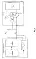
- FIG. 3shows a detecting station connected to a DTE, the DTE being modified to include a low-pass filter.
- FIG. 5shows the logic that generates the test pulses and compares the test pulses with the received pulses.
- FIG. 4shows a detecting station subsection and DTE requiring power.
- FIG. 6shows an exemplary embodiment of the low-pass filter.
- FIG. 7shows the sequence for DPM detection combined with Auto-Negotiation in a basic embodiment of the invention.
- FIG. 8is a flowchart that shows the sequence for DPM detection combined with Auto-Negotiation in a preferred embodiment of the invention.
- a detectoris utilized to detect the presence of device on a transmission line and whether the device requires power.
- the devicecan be data terminal equipment (DTE) or any other device that may require power.
- DTE equipmentincludes any kind of computer, such as notebooks, servers, and laptops; smart VCRs, refrigerators, or any household equipment that could become a smart device; IP telephones, fax machines, modems, televisions, stereos, hand-held devices, or any other conventional equipment requiring power. If the presence of a DTE requiring power is detected, then the detector can supply power to the DTE.
- the described embodimenthas broad applications. For example, a number of areas can benefit from power delivery over a transmission line including IP Telephony, Web Cameras, Wireless Access Points, Industrial Automation, Home Automation, Security Access Control and Monitoring Systems, Point of Sale Terminals, Lighting Control, Gaming and Entertainment Equipment, Building Management, and any other area where power is required.
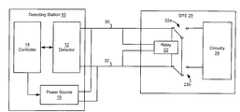
- FIG. 1An exemplary embodiment of the present invention is shown in FIG. 1 with a detecting station 10 connected to a DTE 20 via a two-way transmission line (detector output 30 and detector return 32 ).
- the detecting stationincludes a detector 12 , a controller 14 , and a power source 16 .
- the detector 12provides a direct interface to the DTE.
- the controller 14initiates control and the detection process.
- the detectoris a physical layer transceiver (PHY) with detecting capability.
- PHYphysical layer transceiver
- the controller 14causes the detector 12 to detect whether the DTE 20 is connected to the transmission line and whether the DTE 20 requires power. If the Detector 12 determines that a DTE 20 requiring power is connected to the transmission line, it signals the controller 14 . In response, the controller 14 activates the power source 16 , thereby providing power to the DTE 20 .
- the DTEincludes a relay 22 connected across the two-way transmission line 30 , 32 .
- the switches 22 a , 22 bare used to selectively connect the detector output 30 to the detector return 32 in the power requirement detection mode, and to connect the two-way transmission line 30 , 32 to DTE circuitry 28 once power is applied to the DTE 20 .
- Other devicescan be used to selectively connect the detector output 30 to the detector return 32 such as electronic switches and other conventional devices.
- the detector 12determines whether the connected DTE 20 requires power by sending test pulses to the DTE 20 .
- the relay 22In the default mode (power requirement detection mode), the relay 22 is de-energize causing the detector output 30 to be connected to the detector return 32 through the relay switches 22 a , 22 b .
- any test pulses sent from the detector 10 to the DTE 20are looped back to the detector 12 .
- the detector 12determines that the DTE requires power if the test pulses are looped back from the DTE 20 to the detector 10 .
- the controller 14activates the power source 16 , thereby delivering power over the two-way transmission line 30 , 32 .
- the relay 22is energized causing the relay switches 22 a , 22 b to connect the two-way transmission line 30 , 32 to the DTE circuitry 28 .
- the detectorhas a wide range of application.
- the detectorcould be integrated into a transmission line interface, such as a switch or hub, which links various DTEs onto a local area network (LAN).
- This applicationwould provide a technique for detecting which DTEs, if any, connected to LAN require power, and providing power over the LAN to those DTE's that require it.
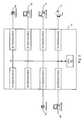
- FIG. 2shows an exemplary embodiment of this with a Fast Ethernet switch 51 having eight detecting stations 40 , 42 , 44 , 46 , 48 , 50 , 52 , 54 .
- Each detecting stationincludes a full-duplex 10/100BASE-TX/FX transceiver (not shown).
- Each transceiverperforms all of the Physical layer interface functions for 10BASE-T Ethernet on CAT 3 , 4 or 5 unshielded twisted pair (UTP) cable and 100BASE-TX Fast Ethernet on CAT 5 UTP cable.
- 100BASE-FXcan be supported at the output of each detecting station through the use of external fiber-optic transceivers.
- the detecting stations 40 , 42 , 44 , 46 , 48 , 50 , 52 , 54are connected to a data bus 58 .
- a CPU 60controls the communication between detecting stations by controlling which detecting stations have access to the data bus 58 .
- Each detecting stationhas a detector that can be connected to a DTE. In the described embodiment, the detecting stations 40 , 42 are not connected to any device.
- the detecting stations 44 , 48are connected to IP telephones 62 , 64 .
- the detecting stations 46 , 50 , 52are connected to computers 66 , 68 , 70 .
- the detecting station 54is connected to a fax machine 72 .
- each detector of each detecting stationsends test pulses to its respective device. Each detector would then wait to see if the test pulses from its respective DTE device is looped back.
- the test pulseswill only be looped back to the detecting stations 44 , 48 .
- the detecting stations 44 , 48will then deliver power to their respective IP telephones over the transmission line.
- the computers 66 , 68 , 70 and the fax machine 72do not require power, and therefore, will not loop back the test pulses to their respective detectors. As a result, the detecting stations 46 , 50 , 52 , 54 will not deliver power over the transmission line.
- the detectoris described in the context of a Fast Ethernet switch, those skilled in the art will appreciate that the detector is likewise suitable for various other applications. Accordingly, the described exemplary application of the detector is by way of example only and not by way of limitation.
- the detectorsIn the context of a Fast Ethernet switch, it is desirable to configure the detectors to prevent failures of DTE devices in the event that the system is wired incorrectly.
- the computer 68which does not require power, could be inadvertently wired directly to the IP telephone 64 . If the IP telephone 64 required power, a switch (see FIG. 1) would connect the two-way transmission line together in the default mode. As a result, the computer 68 would attempt to negotiate data rates with the IP telephone 64 on power up.
- the data rate negotiation in the described exemplary applicationis governed by IEEE 802.3u Clause-28 rules, the contents of which are expressly incorporated herein by reference as though set forth in full.
- an exemplary embodiment of the present inventionutilizes a filter in the front end of the DTE.
- a detecting station 10is shown connected to a DTE 20 ′.
- the detecting station 10is identical to that described with reference to FIG. 1 .
- the DTE 20 ′has been modified to include a low-pass filter 34 connected between the detector output 30 and the detector return 32 through the relay switches 22 a , 22 b when the relay 22 is de-energize.
- the cutoff frequency of the low-pass filter 34is set to filter out the 100 ns FLPs.
- the detectoruses test pulses having pulse widths greater than 100 ns which will pass through the low-pass filter.
- test pulses wide enough to pass the low-pass filter 34would be looped backed through the DTE 20 ′ to the detecting station 10 indicating a requirement for power.
- the detector 10determines whether the connected DTE 20 ′ requires power by sending test pulses to the DTE 20 ′.
- a 150 ns wide pulsecan be used, although those skilled in the art will readily appreciate that the filter can be designed to pass test pulses of any width.
- the pulse width of the test pulsesis programmable. The skilled artisan will also recognize that either a single test pulse or a series of test pulses can be used to detect DTEs requiring power. In the context of a Fast Ethernet switch, economy dictates that a 16 bit word conforming to the IEEE 802.3 standards is used. This standard is already supported in the detector 12 and controller 14 , and therefore, lends way to easy integration of the tests pulses into the detector 10 without any significant increase in complexity.
- the relay 22In the default mode (power requirement detection mode), the relay 22 is de-energize causing the detector output 30 to be connected to the detector return 32 through the relay switches 22 a , 22 b . Thus, any test pulses sent from the detector 10 to the DTE 20 ′ are looped back to the detector 10 through the filter 34 .
- the detector 12determines that the DTE requires power if the test pulses are looped back from the DTE 20 ′ to the detector 10 .
- the controller 12determines that the DTE 20 ′ requires power, it signals the controller 12 .
- the controller 12activates the power source 16 , thereby delivering power over the two-way transmission line 30 , 32 .
- the relay 22Once power is applied to the two-way transmission line 30 , 32 , the relay 22 is energized causing the relay switches 22 a , 22 b to connect the two-way transmission line 30 , 32 to the DTE circuitry 28 .
- the 16-bit word generated by the test pulsescan be a pseudo random word in the described exemplary embodiment. This approach will significantly reduce the risk that two detectors in the Fast Ethernet switch inadvertently wired together will attempt to power one another. If this inadvertent miswiring were to occur, the chances that the detectors would generate the same 16 bit word such that it would appear at each detector as if their respective test pulses were being looped back is 1 ⁇ 2 16 .
- the 16 bit wordcould be an identifier such as a controller address. In other words, the address would be embedded into the 16 bit word. As a result, if two detectors were inadvertently wired together, the exchange of test pulses between them would not be mistaken as a looped back condition because the controller address of each detecting station is different.
- the detectorcould generate a narrow window in time when it expects to receive test pulsed back after transmission. Thus, unless the two detectors are sending test pulses at or near the same time, a looped back condition would not be detected. For example, using the IEEE 802.3 standard, a 16 bit word is transmitted every 8 ms minimum. If the window is set for the worst case round trip delay of each test pulse say 4 us, then the probability that the other detector would transmit its test pulses in the window is 1/2000.
- the first group of test pulseswill have sufficiently wide pulse widths such that they pass through the filter of the DTE.
- the second group of test pulseswill be FLPs of 100 ns width as specified in the IEEE 802.3u Clause-28 rules.
- the detectordetects the first group of pulses and signals the controller. In response, the controller enables the power source which delivers power to the two-way transmission line.
- This approachis useful for detecting a short in the two-way transmission line. For example, if the detector output was shorted to the detector return, both the first and the second group of test pulses would be detected by the detector. This information would be signaled to the controller. The controller would process the results concluding that a short in the two-way transmission line has occurred since both the first and second group of test pulses were received. In response, the controller would not enable the power source.
- FIG. 4shows a detecting station 10 subsection and a DTE requiring power 20 ′.
- the detecting stationincludes logic 100 , transmitter 102 , receiver 104 , a detector transmit transformer 106 , a detector receive transformer 108 , and a power source 110 .
- the DTEincludes DTE circuitry 120 , a receiver 126 , a transmitter 124 , a DTE receive transformer 116 , a DTE transmit transformer 118 , a relay 112 , and a filter 34 .
- the test pulsesare generated by the logic 100 and coupled to the transmitter 102 .
- the output of the transmitteris coupled to the primary winding of the transmit transformer causing the test pulses to be induced into the secondary winding.
- the secondary winding of the transmit transformeris coupled to a DTE power source.
- the power sourceis isolated from the transmitter and receiver to protect their circuitry.
- the test pulses from the secondary winding of the transmitterare transmitted to the DTE.
- the wires between the detecting station and the DTE requiring powerare shown in FIG. 5 between the dashed lines 122 .
- the test pulsesdo not energize the relay 112 because the test pulses are AC.
- the test pulses transmitted to the secondary windings of the DTE transformerare indirect to the primary side of the DTE receive transformer 116 .
- test pulses on transformers 116 , 112are directed through the low-pass filter 84 .
- the primary winding of the DTE receive transformer 116is coupled to the primary winding of the DTE transmit transformer 118 through a low-pass filter 34 .
- the test pulses from the DTE receive transformer 116are directed through filter 34 to the primary winding of the DTE transmit transformer 118 .
- the test pulsesare from the primary winding of the DTE transmit transformer are induced into the secondary winding of the DTE transmit transformer 118 .
- the condition of the absence of the power on the DTE, the receive signal passing through the filter to the transmitter side of the DTEis referred to as the loopback condition.
- the induced test pulses from the secondary winding of the DTE transmit transformersends pulses on the detector return line.
- the test pulses on the detector returnare coupled to the secondary winding of the detector receive transformer 108 , thereby inducing the test pulses into the primary winding of the receiver 104 .
- the logic 100compares the test pulses sent with the test pulses received. If the test pulses match, then a DTE requiring power has been detected. Once the DTE requiring power is detected, the detector supplies power via the transmission line to the DTE requiring power. The power is directed from a power supply 110 of the detector to the detector output onto the transmission wires. The DTE power sink absorbs the power and the DC power activates the relay 112 , thereby closing the switches from the transformers 116 , 118 and connecting the detector with the DTE. The power connection to the DTE requiring power 20 ′ is coming from the detector output of the transformer as opposed to the detector side of the DTE requiring power.
- the power sourcemay have a current limitation in order to prevent hazards in case of a cable short while the detector is powered.
- the transformers 106 , 108 , 116 , 118provide isolation between the detector 10 and the DTE requiring power 20 ′.
- FIG. 5shows the logic 100 that generates the test pulses and compares the test pulses with the received pulses.
- a word generator 84is coupled to a register 82 .
- the word generator 84generates the test pulses which in the prescribed exemplary embodiment is a 16-bit word. In the preferred embodiment, the word generator 84 generates a pseudo-random code word. Alternatively, the word generator 84 is designed to generate a unique identifier, which can be a controller identifier.
- the uniqueness of the word generator outputalso referred to as the unique code word, increases the probability of correctly detecting a DTE requiring power through the loopback connection.
- the controllerinitiates the detection mode by generating an Initiate Detection trigger 80 , which causes the register 82 to latch the output of the word generator 84 .
- the register 82is coupled to a pulse shaping device such as a digital-to-analog converter (DAC) 86 .
- the DACis used to shape the pulse.
- the DACgenerates a link pulse shape in accordance with IEEE 802.3u and IEEE 8802.3
- the digital-to-analog converter (DAC) 86converts the test pulses into analog signals for output to the DTE.
- the controllerindicates the length of the test pulses by writing to register 90 .
- Register 90determines the length of the test pulses by being coupled to the DAC.
- the typical test pulseis 100 ns wide. By programming register 90 , the test pulse width can be widened, such as 20 us or more.
- a signal detecting devicesuch as an analog-to-digital converter (ADC) converts the DTE output analog signals to digital signals.
- the ADCis coupled to a register 93 .
- the register 93is coupled to a comparator 94 and latches the ADC output for use by the comparator 94 .
- the window time periodis programmable.
- the controllerprograms the time window by writing to the programmable register 91 .
- Register 91determines the length of the time window by being coupled to timer 92 .
- the timer 92enables comparing 94 the sent test pulses with the received test pulses for the window time period. If the sent test pulses are the same as the received pulses and the received pulses within the window time, then the comparator indicates a match 95 . If the received pulses are not the same as the sent pulses or are not received within the window time, then the comparator indicates a mismatch 97 .
- the purpose of the window time periodis to improve the probability of correctly matching sent test pulses with received test pulses and reduce the probability of mis-detecting another detector sending the same unique code word.
- the logic 100is controlled via the flow/state diagram in FIGS. 7 and 8 for the basic and preferred embodiments, respectively.
- flow/state diagramis embedded within the IEEE standard 802.3u clause 28 auto-negotiation definition and inter-operates with all the devices designed to that standard.
- the detectorIn addition to configuring the detector to transmit two groups of test pulses, it is also desirable in certain embodiments of the present invention to implement the power source with current limiting capability in the event of a short circuit in the two-way transmission line.
- the low-pass filteris a 3-pole filter with a cutoff frequency of 880 kHz.
- the low pass filtercomprises a 7.0 uH inductor 128 , two 2 nF capacitors connected in parallel 130 , 132 , and a zero ohm resistor 134 .
- the zero ohm resistoris a placeholder to show that the values of the inductor, capacitors, and resistor can have different values, such that the cutoff frequency is 880 kHz.
- the low pass filtercan have any cutoff frequency that passes low frequencies.
- the detectorprovides support for identifying data terminal equipment capable of accepting power via media dependent interface.
- a DTEis typically connected to a Ethernet switch capable of detecting its presence and able to establish signaling with it.
- the process of identifying DTE power via MDI capableis termed DPM.
- the detectorprovides support for an internet-protocol based telephone, known as IP PHONE.
- IP PHONEis one type of DTE.
- the detectoris capable of normal Auto-Negotiation, which is its default state, or a modified Auto-Negotiation when its DPM detection mode is enabled.
- the Auto-Negotiation schemeis embedded within the IEEE 802.3u Clause-28 rules. Therefore, the detector can be connected to either an IP PHONE or a non-IP PHONE without detriment to the detector operation.
- the detectorWhen the detector starts Auto-Negotiation and DPM detection is enabled, it sends a unique Fast Link Pulse (FLP) word that is different from a formal FLP word. If the Link partner is DPM capable, it returns this unique FLP word. Otherwise, the detector may receive the Link partner's word instead of the unique FLP word sent. The detector updates a register containing relevant status bits that the controller (Control) can read. The detector continues to send the unique FLP word if no response is received from the Link partner. The controller, at any time, can disable DPM detection and restart Auto-Negotiation to establish normal link with the Link partner.
- FLPFast Link Pulse
- the detectorUpon power-up the detector defaults to normal mode, non-DPM detection mode, as per the IEEE 802.3u standard.
- the detectorincludes a shadow register, DPM, containing required ‘enable’ and ‘status’ bits for DPM support.
- the detectorsends a unique Fast Link Pulse (FLP) word that is different from a normal FLP word. If the Link partner is a DPM, this unique FLP word externally loops back to the device. Otherwise, the device may receive the Link partner's word instead of its own unique FLP word.
- FLPFast Link Pulse
- the detectoris capable of robustly determining if its partner is DTE type or not. Upon determination, the detector updates a register containing relevant status bits that the controller can read. The detector continues to send the unique FLP word if no response is received form a partner. The controller, at any time, can disable the DPM detection mode and restart the Auto-Negotiation to establish normal link with a Link partner.
- FIG. 7shows the sequence for DPM detection combined with Auto-Negotiation in a basic embodiment of the invention.
- Table 1 and 2show DPM register bits and their description.
- DPM detectioncan be reset or restarted along with auto-negotiation or link loss 160 .
- the controllercan enable DPM detection by setting the DPMDETEN bit to a “1” and restart Auto-Negotiation by setting ANRSTRT bit to a “1” 162 . If these bits are not set, then normal auto-negotiation proceeds 164 .
- the deviceloads an internally generated unique (random) word into the Auto-Negotiation Advertisement register, also called an FLP register 166 , and begins to transmit this FLP word 168 .
- an FLP register 166also called an FLP register 166
- link pulses′ widthcan be increased from a normal 100 ns to 150 ns if LPXTND bit is set to a “1”.
- the link pulse widthcan be increased from 150 ns to 950 ns, in 100 ns increment per FLPWIDTH register, if LPXTND bit is set to a “1”. If LPXTND bit is a “0” then a default link pulse width of 100 ns is used. The wider link pulse enhances the cable reach for the DTE if the external loopback is over CAT 3 cabling.
- the detectorif the unique FLP word is not received from the Link partner, then the detector continues to send the DPM FLP burst 170 . If the unique FLP word is received from the Link partner 172 , then the detector checks if the sent FLP burst matches the received FLP burst 174 . If they match, then the detector sets its DPMSTAT bit to a “1” 176 . The received unique FLP word indicates a DPM detection. If it receives any other FLP word, the detector sets its MISMTCH bit to a “1” 178 , indicating a non-DPM detection.
- the detectorAfter it sets either the DPMSTAT or MISMTCH bit, the detector stops auto-negotiation and waits in the TX-Disable state of the Auto-Negotiation arbitrator state machine.
- the controllerpolls the mutually exclusive DPMSTAT and MISMTCH bits, to determine if a partner is detected and if the partner is DPM capable. If the partner is a DPM capable, the power to the DTE is supplied through the UTP cable. After the partner has been identified through the DPMSTAT or MISMTCH bit, to establish link with the partner, the DPMDETEN bit should be disabled, and Auto-Negotiation process restarted.
- DPM detectioncan be reset or restarted along with auto-negotiation or link loss 180 .
- the controllercan enable DPM detection by setting the DPMDETEN bit to a “1” and restart Auto-Negotiation by setting ANRSTRT bit to a “1” 182 . If these bits are not set, then normal auto-negotiation proceeds 184 and the MISMTCH bit is set to “1” and the DPMSTAT bit is set to “0” 86 .
- the deviceloads an internally generated unique (random) word into the Auto-Negotiation Advertisement register, also called an FLP register 188 , and begins to transmit this DPM FLP word 190 .
- the detectorcontinues to send out an internally generated unique DPM FLP word, FLP burst, during the DPMDETEN mode, until the detector detects energy from the Link partner 192 .
- the detectorwhen the detector detects energy from the Link partner, the detector takes the checks if an FLP word has been received 194 . If no FLP is received, then the detector starts and completes parallel detection 196 , sets MISMTCH bit to a “1”, sets DPMSTAT to “0” 198 , and enters link phase as per the parallel detection. The detector then check whether the received FLP matches the DPM FLP. 100 . If the received FLP word does not match the DPM FLP burst then the detector sets MISMTCH bit to a “1”, sets DPMSTAT to “0” 198 , and completes Auto-Negotiation and enters link phase.
- the detectorsets DPMSTAT bit to a “1” 202 .
- the detectorchecks if the DPMCONT bit is set to “1” 204 . If DPMCONT bit is a “0” then the sytem stops Auto-Negotiation 206 and waits for the controller before taking further action. If DPMCONT bit is a “1” then the detector sends a DPM FLP burst 208 and monitors the state of receive FLP timer and energy from the Link partner.
- the detectorchecks whether the Max FLP Receive timer expired 210 . If the Receive FLP timer has expired, then the detector sets the DPMSTAT bit to a “0” 212 and starts over the DPM detection.
- the detectorchecks if energy is detected 214 . If energy is not detected, then the detector checks if the FLP receive time expired. If energy is detected, then the detector checks whether the FLP has been received 216 . If energy is detected from the Link partner but no FLP is received then the sytem starts and completes parallel detection, sets MISMTCH bit to a “1”, sets DPMSTAT to “0”, and enters link phase as per the parallel detection 196 . If an FLP is received, then the detector checks whether the received FLP matches the DPM FLP burst 118 .
- the detectorIf energy detected from the Link partner is an FLP word and if it matches the DPM FLP burst then the detector returns to sending a DPM FLP burst 108 . If energy detected from the Link partner is an FLP word but it does not match the DPM FLP burst then the sytem sets MISMTCH bit to a “1”, sets DMPSTAT to “0” 86 and completes Auto-Negotiation and enters link phase.
- Table 1gives a bit summary of the register, 0 Fh (15 decimal), in the basic embodiment of the invention.
- the register, 0 Fh (15 decimal)is considered a shadow register, and is referred to as a DPM register.
- the “Spare Control Enable”, bit 7of register 1 Fh must be set.
- Table 2shows a detailed description of the DPM register bits in the basic embodiment of the invention.
- LPXTNDExtend Link Pulse width. When this bit is set to a “1”, the system increases the FLP width from a normal 100 ns to 150 ns.
- MISMTCHis Word Mismatch.
- the Link partner's FLP wordis compared to the unique FLP word sent.
- MISMTCH bitis set to a “1” if the comparison fails indicating that the Link Partner is not DPM capable.
- MISMTCH bitis set to “1” for detecting any legacy Ethernet device: either Auto-Negotiation or forced to 10 or 100 Mbits speed.
- DPMSTATis DPM Status
- the Link partner's FLP wordis compared to the unique FLP word sent. If it matches, the Link Partner is DPM capable and TAT bit is set to a “1”
- ANRSTRTis Restart. This bit, when set to a “1”, restarts the Auto-Negotiation.
- the detectorafter power up, is in a non-DPM detection mode. If DPM detection is needed DPMDETEN bit should be set to a “1” and restart the Auto-Negotiation. Auto-Negotiation can also be restarted by setting bit 9 of reg. 0 (Control Register) to a “1”.
- DPMDETENis DPM detection mode. When this bit is set to a “1”, the detector enables DPM detection when Auto-Negotiation is re-started. Otherwise, the system Auto-Negotiates in a non-DPM detection mode as per the IEEE 802.3u standard. When in DPMDETEN mode, if a legacy Ethernet device is detected through either normal Auto-Negotiation Ability Detect or Parallel Detect paths, the Negotiation process continues to a completion, where link between the two stations is established.
- Table 3shows a detailed description of the MII register, 0 Fh (15 decimal), referred to as a DPM register and its bits definition in the preferred embodiment of the invention.
- Table 4shows a detailed description of the MII register, 0 Fh (15 decimal), referred to as a DPM register and its bits definition.
- FLPWIDTH[ 4 : 0 ] is the FLP width in DPMDETEN mode.
- LPEXTNDis set for a “1” then the FLP pulse width can be changed from a default 100 ns to 150 ns.
- the widthcan be further increased to a maximum of 950 ns in 100 ns increments as specified by the FLPWIDTH, a 5 bits register.
- DPMCONTis Continuous DPM Detect Enable. While in DPMDETEN mode if this bit is set to a “1”, after initially detecting a DPM capable Link partner, the detector continues to monitor the presence of a DPM capable Link Partner. While in this continuous DPM detection mode, if it detects a non DPM Link partner, the detector establishes a link with the Link partner if possible.
- FIG. 7shows the details of the DPM detection procedure combined with Auto-Negotiation.
- LPXTNDis Extend Link Pulse width.
- the detectorincreases the link pulse width from a normal 100 ns to 150 ns. Additionally, the link pulse width can be increased to a maximum of 950 ns to 100 ns increments per register FLPWIDTH.
- MISMTCHis Word Mismatch.
- DPM detectionis enabled, the Link partner's FLP word is compared to the unique FLP word sent.
- MISMTCH bitis set for a “1” if the comparison fails indicating that the Link Partner is not DPM capable.
- DPMSTATis DPM Status.
- the Link partner's FLP wordis compared to the unique FLP word sent. If it matches, the Link Partner is DPM capable and DPMSTAT bit is set to a “1”.
- ANRSTRTis Restart. This bit, when set to a “1”, restarts the Auto-Negotiation.
- the detectorafter power up, is in a non-DPM detection mode. If DPM detection is needed DPMDETEN bit should be set to a “1” and restart the Auto-Negotiation. Auto-Negotiation can also be restarted by setting bit 9 of reg. 0 (Control Register) to a “1”.
- DPMDETENis DPM detection enable. When this bit is set to a “1”, the detector enables DPM detection when Auto-Negotiation is restarted Otherwise, the detector Auto-Negotiates in a non-DPM detection mode as per the IEEE 802 3u standard.
- the detectoris capable of generating interrupts to indicate DPMSTAT bit change if interrupt mode is enabled.
- the detectorhas a maskable interrupt bit in the MII register 1 Ah.
- Bit 12DPMMASK of register 1 Ah, when set to a “1” disables generation of DPMSTST change interrupt.
- Bit 5DPMINT, of register 1 Ah indicates that there has been a change in DPMSTAT bit.
- DPMINTis:DPM Interrupt.
- Bit 5 of MII register 1 Aha read only bit, if read as a “1”, indicates that there has been a DPMSTAT bit change in the DPM detection process. The change indicated could be from a “0” to a “1” or from a “1” to a “0”. Additionally, if interrupt has been enabled and DPMMASK is a “0”, then the detector generates an interrupt. Reading of register 1 Ah clears DPMINT bit and interrupt that was caused by DPMSTAT bit change.
- DPMMASKis DPM Mask.
- bit 12 of MII register 1 Ahwhen set to a “1” disables any interrupt generated by the DPMSTAT change if interrupt is enabled.
- bit 5DPMINT, provides a DPMSTAT change regardless of DPMMASK bit
- FIG. 7flowchart shows the sequence for DPM detection combined with Auto-Negotiation in a basic embodiment of the invention.
- FIG. 8flowchart shows the sequence for DPM detection combined with Auto-Negotiation in a preferred embodiment of the invention.
- Link pulse widthIn DPMDETEN mode if LPXTND bit is set to a “1”, the FLP width is changed from a normal 100 ns to 150 ns. In addition to this, the detector can increase this width in 100 ns increments, as specified by the FLPWIDTH register. A value of “00000”b (default) in the FLPWIDTH register would be equivalent to the basic embodiment of the invention.
- the link pulse widthremains at 150 ns during normal Auto-Negotiation phase. In the preferred embodiment of the invention, the link pulse width is switched back to 100 ns during normal Auto-Negotiation phase.
- the preferred embodiment of the inventionincorporates an additional bit DPMCONT. While in DPMDETEN mode if this bit is set to a “1”, after initially detecting a DPM capable Link partner, the detector continues to monitor the presence of a DPM capable Link partner. While in this continuous DPM detection mode, if it detects a non-DPM Link partner, the detector establishes a Link partner if possible.
- FIG. 8shows the details.
- the DPM detection functionis identical to the basic embodiment if DPMCONT bit is a “0” (default).
- the preferred embodimentprovides a maskable interrupt for the DPMSTAT bit change. This is enabled by setting DPMMASK, bit 12 of MII register 1 Ah, to a “0” if the detector's interrupt bit 14 of MII register 1 Ah is set for a “1”. In the preferred embodiment, if DPMMASK is set to a “1” (default) then the detector does not provide DPMSTAT bit change interrupt as is the case in the basic embodiment.
- the DPM detection processprevents the detector from supplying power to a legacy DTE not equipped to handle power through the MDI.
- the far-end deviceis not a DTE requiring power
- the far-end unit's link detectionis unaffected by the DPM detection mechanism.
- the standard Auto-Negotiation processoccurs in parallel to the DPM detection process, enabling detection of non-DTE requiring power devices while DPM detection is enabled. Randomization in the DPM detection algorithm prevents two detection-enabled stations from simultaneously applying power.
- the DPM detection schemeworks over CAT-3, CAT-5, or better cabling
- the detectoris set to a mode to search for a DTE requiring power.
- the DTE requiring power's RD pairis effectively connected to the TD pair through a low pass filter.
- the detector of the detecting stationtransmits a random code of sufficient uniqueness.
- the DTE requiring poweris detected through the detector of the detecting station receiving its unique random code through the DTE requiring power loopback. Once the detecting station detects the presence of the DTE requiring power, it supplies detector power to the DTE requiring power via an MDI connection
- the detecting stationthen performs an Auto-Negotiation with the now-powered DTE requiring power. During the detection process, if the detecting station receives valid 10Base-T NLPs, 100Base-TX idles, or Auto-Negotiation FLP code-words, it Auto-Negotiates normally.
- the DTE requiring power receive pairis effectively connected to its transmit pair (TD) through a low pass filter.
- This low pass filtercuts-off the legacy link partner's valid data, avoiding network activity.
- the random code signal used for DTE requiring power detectionmust be of sufficiently low frequency content to pass through the filter, as well as two worst-case CAT- 3 cables.
- DPMDETENDPM Detection Mode
- firmwaremust set the DPM Detection Enable bit, DPMDETEN (DPMFON reg, bit 0 ) to a ‘1’, and then set the Auto-Negotiation Restart bit, ANRSTRT (DPM reg, bit 1 ) to a ‘1’.
- setting the ANRSTRT bitcauses a random sequence to be loaded into the Auto-Negotiation Advertisement Transmit register, and the first FLP word transmitted contains this sequence. While this sequence is transmitted, the link pulses are extended to 1.5 times normal pulse width.
- the deviceWhile in the DPMDETEN mode, as long as nothing is received from a link partner, the device continues to transmit the above FLP word. Once a link partner FLP burst is received, if it does not match the FLP word from the device, then the link partner is not DPM capable. In this case, the device sets the DPM Mismatched bit, MISMTCH, (DPM reg, bit 3 ) to a ‘1’.
- the deviceIf the link partner FLP burst received matches the FLP word the device transmitted, it indicates that the device at the other end is a DPM and its relay is closed to loopback the devices transmit data to its receive port. In this case, the device sets the DPM Status bit, DPMSTAT, (DPM reg, bit 2 ).
- the devicestops the Auto-Negotiation process and waits in the TX-Disable state of the Auto-Negotiation Arbitrator State Machine.
- the firmwaremust take the necessary actions, e.g. power up the DPM, and then in either case, disable the DPMDETEN bit and Restart Auto-Negotiation to establish link with the partner.
- the DPM registercontains both the DPMSTAT and MISMTCH bits. Therefore, polling this register alone provides the necessary status information to indicate either a DPM or a normal link partner.
- the detectoris in normal Auto-Negotiation mode upon startup.
- the Firmwareenables the DPMDETEN mode (DPMDETEN bit) and sets the ANRSTRT bit.
- the detectorsends out the DPM random sequence FLP word. While searching for a DPM, if the received FLP burst matches what the detector transmitted, then the remote partner is a DPM.
- the DPMSTAT bitis set and the Auto-Negotiation process is stopped.
- the remote devicewhile searching for a DPM, if a mismatch between the transmitted and received FLP words occurs, then the remote device is not a DPM.
- the MISMTCH bitis set and the Auto-Negotiation process is stopped.
- the firmwaremonitors the DPMSTAT and MISMTCH bits. Once either of these mutually exclusive status bit is set, the firmware clears the DPMDETEN bit and sets the ANRSTRT bit to complete the normal Auto-Negotiation process in order to link up with either the remote DPM or normal link partner.
- the device at the other endalso attempts to search of an DPM device using the same DPM Phone Detection procedure. If the link partner is another embodiment of the invention (another system detector), then the chances of both devices sending out an identical FLP word is 1 in 2 14 .
- the detectorincludes a time windowing scheme. If a matching FLP burst is received within the maximum time allowed for the FLP burst to make a round trip back to its receive port, the DPMSTAT bit is set. In the preferred embodiment, this maximum time is set to 16 us, which is more than the actual maximum round trip time for the longest cable length. The maximum time is programable. Since a device can send out an FLP burst at any time within a 16 ms window, the probability of it sending out the FLP burst in any 16 us span is 1 in 1000. Therefore, the mis-detection probability is 1 in (2 14 multiplied by 1000), or 1 in 16 million events.
- mis-detectionWhen mis-detection does happen, one or both devices erroneously sets the IPSTAT bit. It's then up to the firmware to monitor this mis-detection event and take the appropriate actions.
Landscapes
- Engineering & Computer Science (AREA)
- Computer Networks & Wireless Communication (AREA)
- Signal Processing (AREA)
- Power Engineering (AREA)
- Theoretical Computer Science (AREA)
- General Engineering & Computer Science (AREA)
- Physics & Mathematics (AREA)
- General Physics & Mathematics (AREA)
- Computer Hardware Design (AREA)
- Small-Scale Networks (AREA)
- Remote Monitoring And Control Of Power-Distribution Networks (AREA)
- Communication Control (AREA)
- Burglar Alarm Systems (AREA)
- Analysing Materials By The Use Of Radiation (AREA)
Abstract
Description
| TABLE 1 |
| DPM Register summary |
| ADDR | NAME | 15-5 | 4 | 3 | 2 | 1 | 0 | DEFAULT |
| OFh | DPM | Reserved | LPXTND | MISMTCH | DPMSTAT | ANRSTR | DPMDETEN | 0000h |
| (15d) | ||||||||
| TABLE 2 |
| DPM REGISTER (ADDRESS OFH, 15D) |
| BIT | NAME | R/W | DESCRIPTION | DEFAULT | |
| 15-6 | Reserved | RO | Write as “0”, Ignore when read | 0 | |
| 5 | DPMWINEN | R/ | 0 | Windowing | |
| scheme | |||||
| enable to | |||||
| reduce ip | |||||
| mis- | |||||
| detection | |||||
| probability | |||||
| 4 | LPXTND: Extend Link Pulse width | R/ | 0 = Normal link pulse width (100 ns) | 4 | |
| 1 = Set Link pulse width to 150 ns | |||||
| 3 | MISMTCH: Word | RO | 1 = Fast Link Pulse Word miss match occurred | 0 | |
| during DPM detection | |||||
| 2 | DPMSTAT: | RO | 1 = Link partner is DPM capable | 0 | |
| 1 | ANRSTRT: Restart | R/ | 1 = Restart Auto-Negotiation (identical to Reg. 0 | 0 | |
| bit 9) but used for | |||||
| 0 | DPMDETEN: DPM enable | R/ | 1 = Enable | 0 | |
| TABLE 3 |
| DPM Register Summary (Address OFh, 15d) |
| ADDR | NAME | 15-11 | 10-7 | 6 | 5 | 4 | 3 | 2 | 1 | 0 | DEFAULT |
| OFh | DPM | FLPWIDTH | Reserved | DPMCONT | Reserved | LPXTND | MISMTCH | DPMSTAT | ANRSTR | DPMDETEN | 0000h |
| (15d) | |||||||||||
| TABLE 4 |
| DPM Register (Address OFh, 15d) |
| DE- | |||||
| BIT | NAME | R/W | DESCRIPTION | FAULT | |
| 15- | FLPWIDTH[4:0} | R/W | FLP | 0 | |
| 11 | |||||
| 10-7 | Reserved | RO | Write as “0”, Ignore when | 0 | |
| read | |||||
| 6 | DPMCONT | R/ | 0 = Stop after detecting a | 0 | |
| DPM capable | |||||
| 5 | Reserved | RO | Write as “0”, Ignore when read | 0 | |
| 4 | LPXTND: Extend | R/ | 0 = Normal | 0 | |
| Link Pulse width | (100 ns) | ||||
| 1 = Set Link pulse width to | |||||
| 150 ns | |||||
| 3 | MISMTCH: | RO | 1 = Fast | 0 | |
| mismatch | mismatch | ||||
| occurred during DPM detection | |||||
| indicating that the link partner | |||||
| is a legacy | |||||
| device | |||||
| 2 | DPMSTAT: | RO | 1 = Link partner is | 0 | |
| capable | |||||
| 1 | ANRSTRT: | R/ | 1 = Restart Auto- | 0 | |
| Restart | (identical to Reg. 0 bit 9) but | ||||
| used for | |||||
| 0 | DPMDETEN: | R/W | 1 - | 0 | |
| DPM enable | mode | ||||
| TABLE 5 |
| Interrupt Register (Address 1Ah, 26d) |
| ADDRESS | NAME | 15-13 | 12 | 11-6 | 5 | 4-6 | DEFAULT |
| 1Ah | INTERRUPT | Reserved | DPMMASK | Reserved | DPMINT | Reserved | 9F0Xh |
Claims (62)
Priority Applications (14)
| Application Number | Priority Date | Filing Date | Title |
|---|---|---|---|
| US09/487,738US6571181B1 (en) | 1999-08-11 | 2000-01-19 | System and method for detecting a device requiring power |
| AU66335/00AAU6633500A (en) | 1999-08-11 | 2000-08-11 | System and method for detecting a device requiring power |
| EP00953975AEP1203282B1 (en) | 1999-08-11 | 2000-08-11 | System and method for detecting a device requiring power |
| PCT/US2000/022012WO2001011861A2 (en) | 1999-08-11 | 2000-08-11 | System and method for detecting a device requiring power |
| AT00953975TATE378628T1 (en) | 1999-08-11 | 2000-08-11 | SYSTEM AND METHOD FOR DETECTING A POWER-REQUIRING DEVICE |
| DE60037120TDE60037120T2 (en) | 1999-08-11 | 2000-08-11 | SYSTEM AND METHOD FOR DETECTING A POWERFUL DEVICE |
| US10/124,676US6954708B2 (en) | 1999-08-11 | 2002-04-17 | System and method for detecting a device requiring power |
| US10/124,770US6643595B2 (en) | 1999-08-11 | 2002-04-17 | System and method for detecting a device requiring power |
| US10/446,530US7054779B2 (en) | 1999-08-11 | 2003-05-27 | System and method for detecting a device requiring power |
| US10/669,842US7082372B2 (en) | 1999-08-11 | 2003-09-24 | System and method for detecting a device requiring power |
| US11/125,912US7174259B2 (en) | 1999-08-11 | 2005-05-10 | System and method for detecting a device requiring power |
| US11/204,529US7254495B2 (en) | 1999-08-11 | 2005-08-16 | System and method for detecting a device requiring power |
| US11/459,815US8949049B2 (en) | 1999-08-11 | 2006-07-25 | System and method for detecting a device requiring power |
| US11/835,155US20080033670A1 (en) | 1999-08-11 | 2007-08-07 | System and method for detecting a device requiring power |
Applications Claiming Priority (2)
| Application Number | Priority Date | Filing Date | Title |
|---|---|---|---|
| US14836399P | 1999-08-11 | 1999-08-11 | |
| US09/487,738US6571181B1 (en) | 1999-08-11 | 2000-01-19 | System and method for detecting a device requiring power |
Related Child Applications (3)
| Application Number | Title | Priority Date | Filing Date |
|---|---|---|---|
| US10/124,770DivisionUS6643595B2 (en) | 1999-08-11 | 2002-04-17 | System and method for detecting a device requiring power |
| US10/124,676DivisionUS6954708B2 (en) | 1999-08-11 | 2002-04-17 | System and method for detecting a device requiring power |
| US10/446,530ContinuationUS7054779B2 (en) | 1999-08-11 | 2003-05-27 | System and method for detecting a device requiring power |
Publications (1)
| Publication Number | Publication Date |
|---|---|
| US6571181B1true US6571181B1 (en) | 2003-05-27 |
Family
ID=26845782
Family Applications (9)
| Application Number | Title | Priority Date | Filing Date |
|---|---|---|---|
| US09/487,738Expired - LifetimeUS6571181B1 (en) | 1999-08-11 | 2000-01-19 | System and method for detecting a device requiring power |
| US10/124,770Expired - Fee RelatedUS6643595B2 (en) | 1999-08-11 | 2002-04-17 | System and method for detecting a device requiring power |
| US10/124,676Expired - LifetimeUS6954708B2 (en) | 1999-08-11 | 2002-04-17 | System and method for detecting a device requiring power |
| US10/446,530Expired - LifetimeUS7054779B2 (en) | 1999-08-11 | 2003-05-27 | System and method for detecting a device requiring power |
| US10/669,842Expired - LifetimeUS7082372B2 (en) | 1999-08-11 | 2003-09-24 | System and method for detecting a device requiring power |
| US11/125,912Expired - LifetimeUS7174259B2 (en) | 1999-08-11 | 2005-05-10 | System and method for detecting a device requiring power |
| US11/204,529Expired - LifetimeUS7254495B2 (en) | 1999-08-11 | 2005-08-16 | System and method for detecting a device requiring power |
| US11/459,815Expired - Fee RelatedUS8949049B2 (en) | 1999-08-11 | 2006-07-25 | System and method for detecting a device requiring power |
| US11/835,155AbandonedUS20080033670A1 (en) | 1999-08-11 | 2007-08-07 | System and method for detecting a device requiring power |
Family Applications After (8)
| Application Number | Title | Priority Date | Filing Date |
|---|---|---|---|
| US10/124,770Expired - Fee RelatedUS6643595B2 (en) | 1999-08-11 | 2002-04-17 | System and method for detecting a device requiring power |
| US10/124,676Expired - LifetimeUS6954708B2 (en) | 1999-08-11 | 2002-04-17 | System and method for detecting a device requiring power |
| US10/446,530Expired - LifetimeUS7054779B2 (en) | 1999-08-11 | 2003-05-27 | System and method for detecting a device requiring power |
| US10/669,842Expired - LifetimeUS7082372B2 (en) | 1999-08-11 | 2003-09-24 | System and method for detecting a device requiring power |
| US11/125,912Expired - LifetimeUS7174259B2 (en) | 1999-08-11 | 2005-05-10 | System and method for detecting a device requiring power |
| US11/204,529Expired - LifetimeUS7254495B2 (en) | 1999-08-11 | 2005-08-16 | System and method for detecting a device requiring power |
| US11/459,815Expired - Fee RelatedUS8949049B2 (en) | 1999-08-11 | 2006-07-25 | System and method for detecting a device requiring power |
| US11/835,155AbandonedUS20080033670A1 (en) | 1999-08-11 | 2007-08-07 | System and method for detecting a device requiring power |
Country Status (6)
| Country | Link |
|---|---|
| US (9) | US6571181B1 (en) |
| EP (1) | EP1203282B1 (en) |
| AT (1) | ATE378628T1 (en) |
| AU (1) | AU6633500A (en) |
| DE (1) | DE60037120T2 (en) |
| WO (1) | WO2001011861A2 (en) |
Cited By (30)
| Publication number | Priority date | Publication date | Assignee | Title |
|---|---|---|---|---|
| US20030061522A1 (en)* | 2001-09-26 | 2003-03-27 | D-Link Corporation | Network switching apparatus for supplying power to network communication equipment through twisted pair line |
| US20030084154A1 (en)* | 2001-10-31 | 2003-05-01 | International Business Machines Corporation | Energy-induced process migration |
| US6646546B1 (en)* | 2002-03-05 | 2003-11-11 | Omninet Capital, Llc | Multiple-port gigabit ethernet distribution switch |
| US6651177B1 (en)* | 2000-02-10 | 2003-11-18 | Ncr Corporation | Circuit and method of providing power to an external peripheral |
| US20040049359A1 (en)* | 1999-08-11 | 2004-03-11 | Vafa Rakshani | System and method for detecting a device requiring power |
| US20040146061A1 (en)* | 2003-01-29 | 2004-07-29 | Brian Bisceglia | Method and apparatus for dynamic termination of unused wired connection |
| US20050097369A1 (en)* | 2003-10-23 | 2005-05-05 | Robert Bowser | System and method for power injection and out of band communications on shared medium |
| US20050245127A1 (en)* | 2004-05-03 | 2005-11-03 | Nordin Ronald A | Powered patch panel |
| US20050245254A1 (en)* | 2004-04-29 | 2005-11-03 | Hall Lawrence A | Wireless access point (WAP) |
| US20050254494A1 (en)* | 2000-09-21 | 2005-11-17 | Serconet, Ltd. | Telephone communication system and method over local area network wiring |
| US20050258895A1 (en)* | 2004-05-19 | 2005-11-24 | Dove Daniel J | System for controlling current flow to electronic attachment device |
| US20050264981A1 (en)* | 2004-05-11 | 2005-12-01 | John Anderson | Power sourcing unit for power over ethernet system |
| US20060018668A1 (en)* | 2004-05-10 | 2006-01-26 | Chris Xu | Multi-wavelength pulse generator using time-lens compression |
| US7073077B1 (en)* | 2003-05-09 | 2006-07-04 | National Semiconductor Corporation | Apparatus for cutting power to processing circuitry in a network interface |
| US20060217847A1 (en)* | 2005-03-28 | 2006-09-28 | Adc Telecommunications, Inc. | Power sourcing unit for power over ethernet system |
| US20070222562A1 (en)* | 1999-09-27 | 2007-09-27 | Cisco Technology, Inc. | Method and apparatus for remote powering of device connected to network |
| US20080069014A1 (en)* | 2006-09-19 | 2008-03-20 | Scott Powell | Method and system for an extended range ethernet link discovery signaling |
| US20080069004A1 (en)* | 2002-03-21 | 2008-03-20 | Broadcom Corporation | Auto detection of copper and fiber mode |
| US7366164B1 (en)* | 2001-04-19 | 2008-04-29 | Cisco Technology, Inc. | Method for regulating power for voice over Internet Protocol telephones |
| US20080214140A1 (en)* | 2005-09-28 | 2008-09-04 | Panduit Corp. | Powered patch panel |
| US20080309313A1 (en)* | 2007-06-15 | 2008-12-18 | Apple Inc. | Systems and methods for providing device-to-device handshaking through a power supply signal |
| US7522615B2 (en) | 2002-11-13 | 2009-04-21 | Serconet, Ltd. | Addressable outlet, and a network using same |
| US7552348B1 (en)* | 2001-04-03 | 2009-06-23 | Marvell International Ltd. | Method and apparatus for detecting and supplying power by a first network device to a second network device |
| US7729367B1 (en) | 2001-04-19 | 2010-06-01 | Cisco Technology, Inc. | Method for bring-up of voice over internet protocol telephones |
| US7830858B2 (en) | 1998-07-28 | 2010-11-09 | Mosaid Technologies Incorporated | Local area network of serial intelligent cells |
| US7835386B2 (en) | 1999-07-07 | 2010-11-16 | Mosaid Technologies Incorporated | Local area network for distributing data communication, sensing and control signals |
| US8363797B2 (en) | 2000-03-20 | 2013-01-29 | Mosaid Technologies Incorporated | Telephone outlet for implementing a local area network over telephone lines and a local area network using such outlets |
| US8873586B2 (en) | 2000-04-19 | 2014-10-28 | Conversant Intellectual Property Management Incorporated | Network combining wired and non-wired segments |
| US8902760B2 (en) | 1998-04-10 | 2014-12-02 | Chrimar Systems, Inc. | Network system and optional tethers |
| US11032353B2 (en) | 2004-01-13 | 2021-06-08 | May Patents Ltd. | Information device |
Families Citing this family (64)
| Publication number | Priority date | Publication date | Assignee | Title |
|---|---|---|---|---|
| US6701443B1 (en)* | 2000-06-19 | 2004-03-02 | Cisco Technology, Inc. | Methods and apparatus for discovering a powerability condition of a computer network |
| US7065143B1 (en)* | 2001-02-26 | 2006-06-20 | Nortel Networks Limited | Method and design for increasing signal to noise ratio in xDSL modems |
| US7161911B1 (en) | 2001-04-03 | 2007-01-09 | Marvell International, Ltd | Method and apparatus for autonegotiation between network devices |
| US7519000B2 (en)* | 2002-01-30 | 2009-04-14 | Panduit Corp. | Systems and methods for managing a network |
| US7375532B1 (en) | 2002-06-07 | 2008-05-20 | Marvell International Ltd. | Cable tester |
| US7075283B1 (en) | 2002-06-07 | 2006-07-11 | Marvell International Ltd. | Cable tester |
| US6825672B1 (en) | 2002-06-07 | 2004-11-30 | Marvell International Ltd. | Cable tester |
| US7173431B1 (en) | 2002-06-07 | 2007-02-06 | Marvell International Ltd. | Cable tester |
| US7019533B1 (en) | 2002-06-07 | 2006-03-28 | Marvell International Ltd. | Cable tester |
| US7358745B1 (en) | 2002-06-07 | 2008-04-15 | Marvell International Ltd. | Cable tester |
| US7002353B1 (en) | 2002-06-07 | 2006-02-21 | Marvell International, Ltd. | Cable tester |
| US6980007B1 (en) | 2002-06-07 | 2005-12-27 | Marvell International Ltd. | Cable tester with insertion loss and return loss estimators |
| US7005861B1 (en) | 2002-06-07 | 2006-02-28 | Marvell International Ltd. | Cable tester |
| US6832168B2 (en)* | 2003-04-04 | 2004-12-14 | Hewlett-Packard Development Company, L.P. | Method and system for verifying network device power cabling configuration |
| US20040213161A1 (en)* | 2003-04-22 | 2004-10-28 | Nack David S. | Integrated circuit powered with link pulse energy |
| US7849343B2 (en)* | 2003-06-10 | 2010-12-07 | Microsemi Corp. - Analog Mixed Signal Group Ltd. | Pre-detection of powered devices |
| US7106071B2 (en)* | 2003-06-11 | 2006-09-12 | Broadcom Corporation | Cable diagnostics using time domain reflectometry and applications using the same |
| US7164274B2 (en)* | 2003-06-11 | 2007-01-16 | Broadcom Corporation | Cable diagnostics using time domain reflectometry and applications using the same |
| US7145439B2 (en)* | 2003-10-16 | 2006-12-05 | Powerdsine, Ltd. | Powered device interface circuit |
| US7898406B2 (en)* | 2003-10-16 | 2011-03-01 | Microsemi Corp. - Analoged Mixed Signal Group Ltd | Powered device with priority indicator |
| DE102004046401B4 (en)* | 2004-09-24 | 2006-07-13 | Siemens Ag | Communication system, distribution element and network device |
| US7545057B1 (en) | 2005-01-04 | 2009-06-09 | Marvell International Ltd, | Relay circuitry and switching circuitry for power-over-network devices |
| US7613936B2 (en)* | 2005-01-25 | 2009-11-03 | Linear Technology Corporation | Dual-mode detection of powered device in power over ethernet system |
| US20060164998A1 (en)* | 2005-01-26 | 2006-07-27 | Broadcom Corporation | System and method for detecting added network connections including wiretaps |
| US7564904B2 (en)* | 2005-05-03 | 2009-07-21 | Texas Instruments Incorporated | Apparatus for and method of detection of powered devices over a network |
| US7679371B1 (en) | 2005-05-27 | 2010-03-16 | Marvell International Ltd. | Advanced time domain reflection cable testing |
| US7701862B2 (en)* | 2005-11-25 | 2010-04-20 | Cisco Technology, Inc. | Method and system for PHY loop detection |
| US8725905B2 (en)* | 2006-01-11 | 2014-05-13 | Dell Products L.P. | Power over ethernet powered management and diagnoses of information handling systems |
| JP4705496B2 (en)* | 2006-03-24 | 2011-06-22 | 富士通株式会社 | Feed line monitoring device |
| US8488474B2 (en)* | 2006-03-24 | 2013-07-16 | Fujitsu Limited | Feed line monitor apparatus |
| US7688749B1 (en) | 2006-04-03 | 2010-03-30 | Marvell International Ltd. | Network interface with autonegotiation and cable length measurement |
| US8553720B2 (en) | 2006-04-19 | 2013-10-08 | Marvell World Trade Ltd. | Adaptive speed control for MAC-PHY interfaces |
| US7906973B1 (en) | 2006-06-09 | 2011-03-15 | Marvell International Ltd. | Cable tester |
| US7804784B1 (en) | 2006-08-28 | 2010-09-28 | Marvell International Ltd. | Cable tester |
| US7471014B2 (en)* | 2006-09-01 | 2008-12-30 | Cisco Technology, Inc. | Method and apparatus distributing power to a load in a powered device |
| US9065657B2 (en)* | 2006-12-21 | 2015-06-23 | Silicon Laboratories Inc. | Powered device including a detection signature circuit |
| US7808247B1 (en) | 2007-02-22 | 2010-10-05 | Marvel International Ltd. | Fast cable tester |
| US7808249B1 (en) | 2007-02-22 | 2010-10-05 | Marvell International Ltd. | Methods and apparatus for measuring a length of a cable |
| US8243752B2 (en) | 2007-04-04 | 2012-08-14 | Marvell World Trade Ltd. | Long-reach ethernet for 1000BASE-T and 10GBASE-T |
| US8369782B1 (en) | 2007-08-13 | 2013-02-05 | Marvell International Ltd. | Bluetooth wideband scan mode |
| US8577305B1 (en) | 2007-09-21 | 2013-11-05 | Marvell International Ltd. | Circuits and methods for generating oscillating signals |
| US7974939B2 (en)* | 2007-10-26 | 2011-07-05 | Microsoft Corporation | Processing model-based commands for distributed applications |
| CN101453092B (en)* | 2007-11-29 | 2012-09-19 | 鸿富锦精密工业(深圳)有限公司 | Composite Audio and Power Adapter |
| US8588705B1 (en) | 2007-12-11 | 2013-11-19 | Marvell International Ltd. | System and method of determining Power over Ethernet impairment |
| US8037331B2 (en) | 2008-04-28 | 2011-10-11 | Dell Products L.P. | Energy efficient method to wake host system for charging battery powered portable devices via bus powered external i/o ports |
| US8315564B2 (en)* | 2008-06-16 | 2012-11-20 | Marvell World Trade Ltd. | Short-range wireless communication |
| US8600324B1 (en) | 2008-06-27 | 2013-12-03 | Marvell International Ltd | Circuit and method for adjusting a digitally controlled oscillator |
| US8472968B1 (en) | 2008-08-11 | 2013-06-25 | Marvell International Ltd. | Location-based detection of interference in cellular communications systems |
| US8212376B2 (en)* | 2008-11-14 | 2012-07-03 | Radioshack Corporation | Apparatus and method for providing operative power to powerline-network device |
| US9288764B1 (en) | 2008-12-31 | 2016-03-15 | Marvell International Ltd. | Discovery-phase power conservation |
| US8472427B1 (en) | 2009-04-06 | 2013-06-25 | Marvell International Ltd. | Packet exchange arbitration for coexisting radios |
| US8532041B1 (en) | 2009-04-24 | 2013-09-10 | Marvell International Ltd. | Method for transmitting information in a regulated spectrum and network configured to operate in the regulated spectrum |
| US9066369B1 (en) | 2009-09-16 | 2015-06-23 | Marvell International Ltd. | Coexisting radio communication |
| US8767771B1 (en) | 2010-05-11 | 2014-07-01 | Marvell International Ltd. | Wakeup beacons for mesh networks |
| KR101616491B1 (en) | 2010-10-20 | 2016-04-28 | 마벨 월드 트레이드 리미티드 | Pre-association discovery |
| US9130746B1 (en) | 2011-01-27 | 2015-09-08 | Marvell International Ltd. | Single pair PHY with auto-negotiation |
| US8750278B1 (en) | 2011-05-26 | 2014-06-10 | Marvell International Ltd. | Method and apparatus for off-channel device invitation |
| US8983557B1 (en) | 2011-06-30 | 2015-03-17 | Marvell International Ltd. | Reducing power consumption of a multi-antenna transceiver |
| US9125216B1 (en) | 2011-09-28 | 2015-09-01 | Marvell International Ltd. | Method and apparatus for avoiding interference among multiple radios |
| WO2013119810A1 (en) | 2012-02-07 | 2013-08-15 | Marvell World Trade Ltd. | Method and apparatus for multi-network communication |
| US9450649B2 (en) | 2012-07-02 | 2016-09-20 | Marvell World Trade Ltd. | Shaping near-field transmission signals |
| US10135626B2 (en)* | 2015-04-14 | 2018-11-20 | Avago Technologies General Ip (Singapore) Pte. Ltd. | Power coupling circuits for single-pair ethernet with automotive applications |
| US9942172B2 (en)* | 2016-02-18 | 2018-04-10 | Dell Products Lp | Auto-negotiate extension for network connections |
| WO2019044782A1 (en)* | 2017-09-01 | 2019-03-07 | ソニー株式会社 | Cable and connection device |
Citations (11)
| Publication number | Priority date | Publication date | Assignee | Title |
|---|---|---|---|---|
| US4686696A (en)* | 1985-12-02 | 1987-08-11 | Keptel, Inc. | Transmission line signal sensing circuit employing means for conserving power, especially for use with a telephone disconnect circuit, and associated method |
| US5406260A (en) | 1992-12-18 | 1995-04-11 | Chrimar Systems, Inc. | Network security system for detecting removal of electronic equipment |
| US5432946A (en)* | 1991-04-11 | 1995-07-11 | International Business Machines Corp. | LAN server personal computer with unattended activation capability |
| JPH07302141A (en) | 1994-05-02 | 1995-11-14 | Wacom Co Ltd | Interface device and its power control method |
| US5657257A (en)* | 1994-09-28 | 1997-08-12 | Samsung Electronics Co., Ltd. | Power-supply controller of computer |
| US5796965A (en) | 1996-06-14 | 1998-08-18 | Texas Instruments Incorporated | Intelligent power circuit for external data drive |
| GB2325119A (en) | 1997-03-24 | 1998-11-11 | Nec Corp | External power supply for a mobile communications device |
| US6049885A (en)* | 1994-10-20 | 2000-04-11 | Advanced Micro Devices, Inc. | Method and apparatus for allowing a remote node to awaken a sleeping node of a network |
| US6085328A (en)* | 1998-01-20 | 2000-07-04 | Compaq Computer Corporation | Wake up of a sleeping computer using I/O snooping and imperfect packet filtering |
| US6272645B1 (en)* | 1998-08-12 | 2001-08-07 | Windbond Electronics Corp. | Method and control circuit for waking up a computer system from standby mode |
| US6339792B1 (en)* | 1998-02-27 | 2002-01-15 | International Business Machines Corporation | Dual two byte process for fast wake-up-on LAN frame detection |
Family Cites Families (58)
| Publication number | Priority date | Publication date | Assignee | Title |
|---|---|---|---|---|
| US4218592A (en)* | 1967-03-14 | 1980-08-19 | Gte Products Corporation | Telephone analyzer for detection of clandestine devices |
| US3715707A (en)* | 1971-03-16 | 1973-02-06 | Westinghouse Electric Corp | Terminal block with snap-in components |
| US3833888A (en)* | 1973-02-05 | 1974-09-03 | Honeywell Inf Systems | General purpose digital processor for terminal devices |
| US3920894A (en)* | 1974-03-11 | 1975-11-18 | Bell Telephone Labor Inc | Pseudo-random parallel word generator |
| US4041381A (en)* | 1974-10-09 | 1977-08-09 | Lim Ching Hwa | Methods and equipment for testing reflection points of transmission lines |
| US4023103A (en)* | 1976-01-26 | 1977-05-10 | The United States Of America As Represented By The Secretary Of The Army | Synchronizer for frequency hopping receiver |
| US4160884A (en)* | 1978-02-06 | 1979-07-10 | Wescom, Inc. | Power regulation system for repeatered telephone transmission lines |
| JPH0340401B2 (en)* | 1980-09-30 | 1991-06-18 | ||
| DE3412317A1 (en)* | 1984-04-03 | 1985-10-03 | C.A. Weidmüller GmbH & Co, 4930 Detmold | LADDER CONNECTION FOR LAMINATED PCB |
| EP0271594B1 (en)* | 1986-12-16 | 1992-04-22 | Weidmüller Interface GmbH & Co. | Clamping device |
| JPH0264261U (en)* | 1988-11-04 | 1990-05-15 | ||
| NO303200B1 (en)* | 1988-11-04 | 1998-06-08 | Merlin Gerin | Building engineering control unit with two-wire data and power supply line |
| GB2235119A (en) | 1989-08-25 | 1991-02-27 | Challis Hircock Peter | Protective devices for the legs of horses |
| JPH0388542A (en)* | 1989-08-31 | 1991-04-12 | Toshiba Corp | Telephone terminal device |
| US5381472A (en)* | 1990-08-10 | 1995-01-10 | Tamura Electric Works, Ltd. | Power source control apparatus for telephone set |
| US5535238A (en)* | 1990-11-16 | 1996-07-09 | Interdigital Technology Corporation | Spread spectrum adaptive power control communications system and method |
| GB9027716D0 (en)* | 1990-12-20 | 1991-02-13 | British Telecomm | Optical communications system |
| US5216704A (en)* | 1991-06-12 | 1993-06-01 | Coherent Communications Systems Corp. | Method for remote power fail detection and maintaining continuous operation for data and voice devices operating over local loops |
| EP0596648A1 (en)* | 1992-11-02 | 1994-05-11 | National Semiconductor Corporation | Network link endpoint capability detection |
| US5390197A (en)* | 1992-12-04 | 1995-02-14 | Hughes Aircraft Company | Vestigial identification for co-channel interference in cellular communications |
| US5410754A (en)* | 1993-07-22 | 1995-04-25 | Minute Makers, Inc. | Bi-directional wire-line to local area network interface and method |
| US5343514A (en)* | 1993-12-10 | 1994-08-30 | Snyder Gary K | Telephone line powered system |
| US5451865A (en)* | 1994-02-25 | 1995-09-19 | General Electric Company | Method and apparatus for sensing an input current with a bridge circuit |
| US5608792A (en)* | 1994-04-13 | 1997-03-04 | British Telecommunications Public Limited Company | Apparatus for drawing and processing electrical power from a communications line |
| US5553138A (en)* | 1994-05-13 | 1996-09-03 | Compaq Computer Corporation | Telephone line sourced power supply |
| US5517172A (en)* | 1994-09-19 | 1996-05-14 | Chiu; Manfred F. | Method and apparatus for powering and signaling over a single wire pair |
| JPH08102775A (en)* | 1994-09-29 | 1996-04-16 | Sony Corp | Cordless telephone set |
| US5717306A (en)* | 1994-11-18 | 1998-02-10 | Shipp; John I. | Battery identification and power interrupt system |
| US5445543A (en)* | 1995-01-30 | 1995-08-29 | Williams; Paul R. | Slip lug adaptor apparatus |
| US5958056A (en)* | 1995-05-26 | 1999-09-28 | Intel Corporation | Method and apparatus for selecting operating voltages in a backplane bus |
| US5674079A (en)* | 1995-05-31 | 1997-10-07 | Electric Motion Company, Inc. | Ground lug |
| US5742602A (en)* | 1995-07-12 | 1998-04-21 | Compaq Computer Corporation | Adaptive repeater system |
| JP3458026B2 (en)* | 1995-09-14 | 2003-10-20 | Nke株式会社 | Control and monitoring system |
| AUPN547695A0 (en)* | 1995-09-15 | 1995-10-12 | H.P.M. Industries Pty Limited | Electrical control system |
| US5764694A (en)* | 1996-01-25 | 1998-06-09 | Rockwell International Corporation | Self-testing and evaluation system |
| US5754870A (en)* | 1996-02-16 | 1998-05-19 | New Media Corp. | Power management of a computer plug-in card having a remote data link |
| US5802169A (en)* | 1996-04-11 | 1998-09-01 | Intervoice Limited Partnership | System and method for transmission system automatic impedance matching |
| JPH10164668A (en)* | 1996-11-29 | 1998-06-19 | Canon Inc | Data communication system, data communication device, and recording medium storing data communication control program |
| US5923363A (en)* | 1997-03-06 | 1999-07-13 | Elbex Video Ltd. | Apparatus for powering a television interphone monitor via a signal transmission line |
| US5923663A (en)* | 1997-03-24 | 1999-07-13 | Compaq Computer Corporation | Method and apparatus for automatically detecting media connected to a network port |
| US6449348B1 (en)* | 1997-05-29 | 2002-09-10 | 3Com Corporation | Power transfer apparatus for use by network devices including telephone equipment |
| US5994998A (en)* | 1997-05-29 | 1999-11-30 | 3Com Corporation | Power transfer apparatus for concurrently transmitting data and power over data wires |
| US5991885A (en)* | 1997-06-11 | 1999-11-23 | Clarinet Systems, Inc. | Method and apparatus for detecting the presence of a remote device and providing power thereto |
| KR100238581B1 (en)* | 1997-07-02 | 2000-01-15 | 윤종용 | Apparatus and method for controlling power of display device using tact switch |
| US6310953B1 (en)* | 1997-07-24 | 2001-10-30 | Fujitsu Limited | Subscriber circuit |
| US6256518B1 (en)* | 1997-10-10 | 2001-07-03 | At&T Corp. | System for providing power to a wireless system |
| US6031431A (en)* | 1997-11-07 | 2000-02-29 | Hitachi America, Ltd. | Methods and apparatus for implementing modulators and programmable filters |
| US6366143B1 (en)* | 1998-05-01 | 2002-04-02 | Kye Systems Corp. | Power shut-off and recovery circuit for data communication devices |
| JP3539879B2 (en)* | 1998-12-15 | 2004-07-07 | アルプス電気株式会社 | Computer power-up device |
| US6473608B1 (en)* | 1999-01-12 | 2002-10-29 | Powerdsine Ltd. | Structure cabling system |
| US6643566B1 (en)* | 1999-01-12 | 2003-11-04 | Powerdsine Ltd. | System for power delivery over data communication cabling infrastructure |
| US6218930B1 (en)* | 1999-03-10 | 2001-04-17 | Merlot Communications | Apparatus and method for remotely powering access equipment over a 10/100 switched ethernet network |
| US6606383B1 (en)* | 1999-04-19 | 2003-08-12 | Adtran Inc. | Automatic remote termination sensing and line powering scheme |
| US6571181B1 (en)* | 1999-08-11 | 2003-05-27 | Broadcom Corporation | System and method for detecting a device requiring power |
| US6762675B1 (en)* | 1999-09-27 | 2004-07-13 | Cisco Technology, Inc. | Method and apparatus for remote powering of device connected to network |
| DE19951789A1 (en)* | 1999-10-27 | 2001-05-03 | Patent Treuhand Ges Fuer Elektrische Gluehlampen Mbh | Connection terminal |
| US6535983B1 (en)* | 1999-11-08 | 2003-03-18 | 3Com Corporation | System and method for signaling and detecting request for power over ethernet |
| DE19963962C1 (en)* | 1999-12-31 | 2001-03-22 | Bosch Gmbh Robert | Pseudo-random generator for radio transmitter or receiver uses registers coupled to arithmetic-logic unit providing pseudo-random words and processor controlling pseudo-random generator sequence |
- 2000
- 2000-01-19USUS09/487,738patent/US6571181B1/ennot_activeExpired - Lifetime
- 2000-08-11EPEP00953975Apatent/EP1203282B1/ennot_activeExpired - Lifetime
- 2000-08-11WOPCT/US2000/022012patent/WO2001011861A2/enactiveIP Right Grant
- 2000-08-11ATAT00953975Tpatent/ATE378628T1/ennot_activeIP Right Cessation
- 2000-08-11AUAU66335/00Apatent/AU6633500A/ennot_activeAbandoned
- 2000-08-11DEDE60037120Tpatent/DE60037120T2/ennot_activeExpired - Lifetime
- 2002
- 2002-04-17USUS10/124,770patent/US6643595B2/ennot_activeExpired - Fee Related
- 2002-04-17USUS10/124,676patent/US6954708B2/ennot_activeExpired - Lifetime
- 2003
- 2003-05-27USUS10/446,530patent/US7054779B2/ennot_activeExpired - Lifetime
- 2003-09-24USUS10/669,842patent/US7082372B2/ennot_activeExpired - Lifetime
- 2005
- 2005-05-10USUS11/125,912patent/US7174259B2/ennot_activeExpired - Lifetime
- 2005-08-16USUS11/204,529patent/US7254495B2/ennot_activeExpired - Lifetime
- 2006
- 2006-07-25USUS11/459,815patent/US8949049B2/ennot_activeExpired - Fee Related
- 2007
- 2007-08-07USUS11/835,155patent/US20080033670A1/ennot_activeAbandoned
Patent Citations (11)
| Publication number | Priority date | Publication date | Assignee | Title |
|---|---|---|---|---|
| US4686696A (en)* | 1985-12-02 | 1987-08-11 | Keptel, Inc. | Transmission line signal sensing circuit employing means for conserving power, especially for use with a telephone disconnect circuit, and associated method |
| US5432946A (en)* | 1991-04-11 | 1995-07-11 | International Business Machines Corp. | LAN server personal computer with unattended activation capability |
| US5406260A (en) | 1992-12-18 | 1995-04-11 | Chrimar Systems, Inc. | Network security system for detecting removal of electronic equipment |
| JPH07302141A (en) | 1994-05-02 | 1995-11-14 | Wacom Co Ltd | Interface device and its power control method |
| US5657257A (en)* | 1994-09-28 | 1997-08-12 | Samsung Electronics Co., Ltd. | Power-supply controller of computer |
| US6049885A (en)* | 1994-10-20 | 2000-04-11 | Advanced Micro Devices, Inc. | Method and apparatus for allowing a remote node to awaken a sleeping node of a network |
| US5796965A (en) | 1996-06-14 | 1998-08-18 | Texas Instruments Incorporated | Intelligent power circuit for external data drive |
| GB2325119A (en) | 1997-03-24 | 1998-11-11 | Nec Corp | External power supply for a mobile communications device |
| US6085328A (en)* | 1998-01-20 | 2000-07-04 | Compaq Computer Corporation | Wake up of a sleeping computer using I/O snooping and imperfect packet filtering |
| US6339792B1 (en)* | 1998-02-27 | 2002-01-15 | International Business Machines Corporation | Dual two byte process for fast wake-up-on LAN frame detection |
| US6272645B1 (en)* | 1998-08-12 | 2001-08-07 | Windbond Electronics Corp. | Method and control circuit for waking up a computer system from standby mode |
Non-Patent Citations (2)
| Title |
|---|
| Fausti et al., "Remote Powered Data Transmission System," Firenze, IEEE, US, vol. Conf. 11, pp. 16.3 1-05 (Oct. 15, 1989). |
| Media Access Control (MAC) Parameters, Physical Layer, Medium Attachment Units, and Repeater for 100 Mb/s Operation, Type 100BASE-T (Clauses 21-30), pp. 1-393, IEEE Std 802-3u-1995 (Supplement to ISO/IEC 8802-3: 1993 [ANSI/IEEE Std 802.3, 1993 Edition]), Published 1995 U.S.A. |
Cited By (77)
| Publication number | Priority date | Publication date | Assignee | Title |
|---|---|---|---|---|
| US8942107B2 (en) | 1998-04-10 | 2015-01-27 | Chrimar Systems, Inc. | Piece of ethernet terminal equipment |
| US9812825B2 (en) | 1998-04-10 | 2017-11-07 | Chrimar Systems, Inc. | Ethernet device |
| US9049019B2 (en) | 1998-04-10 | 2015-06-02 | Chrimar Systems, Inc. | Network equipment and optional tether |
| US9019838B2 (en) | 1998-04-10 | 2015-04-28 | Chrimar Systems, Inc. | Central piece of network equipment |
| US8902760B2 (en) | 1998-04-10 | 2014-12-02 | Chrimar Systems, Inc. | Network system and optional tethers |
| US8867523B2 (en) | 1998-07-28 | 2014-10-21 | Conversant Intellectual Property Management Incorporated | Local area network of serial intelligent cells |
| US8325636B2 (en) | 1998-07-28 | 2012-12-04 | Mosaid Technologies Incorporated | Local area network of serial intelligent cells |
| US7852874B2 (en) | 1998-07-28 | 2010-12-14 | Mosaid Technologies Incorporated | Local area network of serial intelligent cells |
| US8885659B2 (en) | 1998-07-28 | 2014-11-11 | Conversant Intellectual Property Management Incorporated | Local area network of serial intelligent cells |
| US8885660B2 (en) | 1998-07-28 | 2014-11-11 | Conversant Intellectual Property Management Incorporated | Local area network of serial intelligent cells |
| US7830858B2 (en) | 1998-07-28 | 2010-11-09 | Mosaid Technologies Incorporated | Local area network of serial intelligent cells |
| US7969917B2 (en) | 1998-07-28 | 2011-06-28 | Mosaid Technologies Incorporated | Local area network of serial intelligent cells |
| US8908673B2 (en) | 1998-07-28 | 2014-12-09 | Conversant Intellectual Property Management Incorporated | Local area network of serial intelligent cells |
| US7986708B2 (en) | 1998-07-28 | 2011-07-26 | Mosaid Technologies Incorporated | Local area network of serial intelligent cells |
| US8121132B2 (en) | 1999-07-07 | 2012-02-21 | Mosaid Technologies Incorporated | Local area network for distributing data communication, sensing and control signals |
| US8582598B2 (en) | 1999-07-07 | 2013-11-12 | Mosaid Technologies Incorporated | Local area network for distributing data communication, sensing and control signals |
| US7835386B2 (en) | 1999-07-07 | 2010-11-16 | Mosaid Technologies Incorporated | Local area network for distributing data communication, sensing and control signals |
| US7054779B2 (en)* | 1999-08-11 | 2006-05-30 | Broadcom Corporation | System and method for detecting a device requiring power |
| US20040049359A1 (en)* | 1999-08-11 | 2004-03-11 | Vafa Rakshani | System and method for detecting a device requiring power |
| US7174259B2 (en) | 1999-08-11 | 2007-02-06 | Broadcom Corporation | System and method for detecting a device requiring power |
| US20070222562A1 (en)* | 1999-09-27 | 2007-09-27 | Cisco Technology, Inc. | Method and apparatus for remote powering of device connected to network |
| US7821379B2 (en)* | 1999-09-27 | 2010-10-26 | Cisco Technology, Inc. | Method and apparatus for remote powering of device connected to network |
| US6651177B1 (en)* | 2000-02-10 | 2003-11-18 | Ncr Corporation | Circuit and method of providing power to an external peripheral |
| US8363797B2 (en) | 2000-03-20 | 2013-01-29 | Mosaid Technologies Incorporated | Telephone outlet for implementing a local area network over telephone lines and a local area network using such outlets |
| US8855277B2 (en) | 2000-03-20 | 2014-10-07 | Conversant Intellectual Property Managment Incorporated | Telephone outlet for implementing a local area network over telephone lines and a local area network using such outlets |
| US8873586B2 (en) | 2000-04-19 | 2014-10-28 | Conversant Intellectual Property Management Incorporated | Network combining wired and non-wired segments |
| US8982904B2 (en) | 2000-04-19 | 2015-03-17 | Conversant Intellectual Property Management Inc. | Network combining wired and non-wired segments |
| US8817779B2 (en) | 2000-09-21 | 2014-08-26 | Conversant Intellectual Property Management Incorporated | Telephone communication system and method over local area network wiring |
| US20110038368A1 (en)* | 2000-09-21 | 2011-02-17 | Mosaid Technologies Incorporated | Telephone communication system and method over local area network wiring |
| US7480233B2 (en) | 2000-09-21 | 2009-01-20 | Serconet Ltd. | Telephone communication system and method over local area network wiring |
| US7489709B2 (en) | 2000-09-21 | 2009-02-10 | Serconet Ltd. | Telephone communication system and method over local area network wiring |
| US7843799B2 (en) | 2000-09-21 | 2010-11-30 | Mosaid Technologies Incorporated | Telephone communication system and method over local area network wiring |
| US7447144B2 (en) | 2000-09-21 | 2008-11-04 | Serconet, Ltd. | Telephone communication system and method over local area network wiring |
| US20050254494A1 (en)* | 2000-09-21 | 2005-11-17 | Serconet, Ltd. | Telephone communication system and method over local area network wiring |
| US8619538B2 (en) | 2000-09-21 | 2013-12-31 | Mosaid Technologies Incorporated | Communication system and method over local area network wiring |
| US7552348B1 (en)* | 2001-04-03 | 2009-06-23 | Marvell International Ltd. | Method and apparatus for detecting and supplying power by a first network device to a second network device |
| US7729367B1 (en) | 2001-04-19 | 2010-06-01 | Cisco Technology, Inc. | Method for bring-up of voice over internet protocol telephones |
| US8194689B2 (en) | 2001-04-19 | 2012-06-05 | Cisco Technology, Inc. | Method for bring-up of voice over internet protocol telephones |
| US20100220631A1 (en)* | 2001-04-19 | 2010-09-02 | Cisco Technology, Inc. | Method for Bring-Up of Voice Over Internet Protocol Telephones |
| US7366164B1 (en)* | 2001-04-19 | 2008-04-29 | Cisco Technology, Inc. | Method for regulating power for voice over Internet Protocol telephones |
| US20030061522A1 (en)* | 2001-09-26 | 2003-03-27 | D-Link Corporation | Network switching apparatus for supplying power to network communication equipment through twisted pair line |
| US7162650B2 (en)* | 2001-09-26 | 2007-01-09 | D-Link Corporation | Network switching apparatus for supplying power to network communication equipment through twisted pair line |
| US6985952B2 (en)* | 2001-10-31 | 2006-01-10 | International Business Machines Corporation | Energy-induced process migration |
| US20030084154A1 (en)* | 2001-10-31 | 2003-05-01 | International Business Machines Corporation | Energy-induced process migration |
| US6646546B1 (en)* | 2002-03-05 | 2003-11-11 | Omninet Capital, Llc | Multiple-port gigabit ethernet distribution switch |
| US20080069004A1 (en)* | 2002-03-21 | 2008-03-20 | Broadcom Corporation | Auto detection of copper and fiber mode |
| US9014014B2 (en)* | 2002-03-21 | 2015-04-21 | Broadcom Corporation | Auto detection of copper and fiber mode |
| US7522615B2 (en) | 2002-11-13 | 2009-04-21 | Serconet, Ltd. | Addressable outlet, and a network using same |
| US7990908B2 (en) | 2002-11-13 | 2011-08-02 | Mosaid Technologies Incorporated | Addressable outlet, and a network using the same |
| US7911992B2 (en) | 2002-11-13 | 2011-03-22 | Mosaid Technologies Incorporated | Addressable outlet, and a network using the same |
| US8295185B2 (en) | 2002-11-13 | 2012-10-23 | Mosaid Technologies Inc. | Addressable outlet for use in wired local area network |
| US8098681B2 (en)* | 2003-01-29 | 2012-01-17 | Avaya Inc. | Method and apparatus for dynamic termination of unused wired connection |
| US20040146061A1 (en)* | 2003-01-29 | 2004-07-29 | Brian Bisceglia | Method and apparatus for dynamic termination of unused wired connection |
| US7073077B1 (en)* | 2003-05-09 | 2006-07-04 | National Semiconductor Corporation | Apparatus for cutting power to processing circuitry in a network interface |
| US20050097369A1 (en)* | 2003-10-23 | 2005-05-05 | Robert Bowser | System and method for power injection and out of band communications on shared medium |
| US7583703B2 (en)* | 2003-10-23 | 2009-09-01 | Cisco Technology Inc. | System and method for power injection and out of band communications on shared medium |
| US11032353B2 (en) | 2004-01-13 | 2021-06-08 | May Patents Ltd. | Information device |
| US20050245254A1 (en)* | 2004-04-29 | 2005-11-03 | Hall Lawrence A | Wireless access point (WAP) |
| US7455527B2 (en) | 2004-05-03 | 2008-11-25 | Panduit Corp. | Powered patch panel |
| US20050245127A1 (en)* | 2004-05-03 | 2005-11-03 | Nordin Ronald A | Powered patch panel |
| US20060018668A1 (en)* | 2004-05-10 | 2006-01-26 | Chris Xu | Multi-wavelength pulse generator using time-lens compression |
| US7942701B2 (en) | 2004-05-11 | 2011-05-17 | Adc Telecommunications, Inc. | Power sourcing unit for power over ethernet system |
| US20050264981A1 (en)* | 2004-05-11 | 2005-12-01 | John Anderson | Power sourcing unit for power over ethernet system |
| US20080178014A1 (en)* | 2004-05-11 | 2008-07-24 | Adc Telecommunications, Inc. | Power Sourcing Unit for Power Over Ethernet System |
| US7316586B2 (en) | 2004-05-11 | 2008-01-08 | Adc Telecommunications, Inc. | Power sourcing unit for power over ethernet system |
| US7577855B2 (en)* | 2004-05-19 | 2009-08-18 | Hewlett-Packard Development Company, L.P. | System for controlling current flow to electronic attachment device |
| US20050258895A1 (en)* | 2004-05-19 | 2005-11-24 | Dove Daniel J | System for controlling current flow to electronic attachment device |
| US20060217847A1 (en)* | 2005-03-28 | 2006-09-28 | Adc Telecommunications, Inc. | Power sourcing unit for power over ethernet system |
| US7978845B2 (en) | 2005-09-28 | 2011-07-12 | Panduit Corp. | Powered patch panel |
| US20080214140A1 (en)* | 2005-09-28 | 2008-09-04 | Panduit Corp. | Powered patch panel |
| US8867564B2 (en)* | 2006-09-19 | 2014-10-21 | Broadcom Corporation | Method and system for an extended range ethernet link discovery signaling |
| US9461809B2 (en) | 2006-09-19 | 2016-10-04 | Broadcom Corporation | Method and system for an extended range ethernet link discovery signaling |
| US20080069014A1 (en)* | 2006-09-19 | 2008-03-20 | Scott Powell | Method and system for an extended range ethernet link discovery signaling |
| US8812883B2 (en)* | 2007-06-15 | 2014-08-19 | Apple Inc. | Systems and methods for providing device-to-device handshaking through a power supply signal |
| US20080309313A1 (en)* | 2007-06-15 | 2008-12-18 | Apple Inc. | Systems and methods for providing device-to-device handshaking through a power supply signal |
| US20130013940A1 (en)* | 2007-06-15 | 2013-01-10 | Apple Inc. | Systems and methods for providing device-to-device handshaking through a power supply signal |
| US8332664B2 (en)* | 2007-06-15 | 2012-12-11 | Apple Inc. | Systems and methods for providing device-to-device handshaking through a power supply signal |
Also Published As
| Publication number | Publication date |
|---|---|
| US20060034376A1 (en) | 2006-02-16 |
| AU6633500A (en) | 2001-03-05 |
| US20080033670A1 (en) | 2008-02-07 |
| US20050213637A1 (en) | 2005-09-29 |
| EP1203282A2 (en) | 2002-05-08 |
| US7174259B2 (en) | 2007-02-06 |
| US20030033098A1 (en) | 2003-02-13 |
| US6643595B2 (en) | 2003-11-04 |
| US20060258290A1 (en) | 2006-11-16 |
| US8949049B2 (en) | 2015-02-03 |
| WO2001011861A3 (en) | 2001-11-15 |
| US7054779B2 (en) | 2006-05-30 |
| WO2001011861A2 (en) | 2001-02-15 |
| ATE378628T1 (en) | 2007-11-15 |
| US20040049359A1 (en) | 2004-03-11 |
| US20030154038A1 (en) | 2003-08-14 |
| DE60037120T2 (en) | 2008-09-04 |
| US6954708B2 (en) | 2005-10-11 |
| US7082372B2 (en) | 2006-07-25 |
| EP1203282B1 (en) | 2007-11-14 |
| DE60037120D1 (en) | 2007-12-27 |
| US7254495B2 (en) | 2007-08-07 |
| US20040064275A1 (en) | 2004-04-01 |
Similar Documents
| Publication | Publication Date | Title |
|---|---|---|
| US6571181B1 (en) | System and method for detecting a device requiring power | |
| US7849351B2 (en) | Power and data redundancy in a single wiring closet | |
| JP2909084B2 (en) | Run communication device and media adapter used for it | |
| US8549331B2 (en) | Redundant power and data in a wired data telecommunications network | |
| US7724650B2 (en) | Multi-station physical layer communication over TP cable | |
| US5991885A (en) | Method and apparatus for detecting the presence of a remote device and providing power thereto | |
| US6640308B1 (en) | System and method of powering and communicating field ethernet device for an instrumentation and control using a single pair of powered ethernet wire | |
| US8042006B2 (en) | Automatic system for power and data redundancy in a wired data telecommunications network | |
| US5353353A (en) | Repeater security system | |
| US7724692B1 (en) | Method and apparatus for autonegotiation between network devices | |
| RU2639957C2 (en) | Equipment, method and software computer tool for data transfer with reduced power consumption during connection inactivity time | |
| US7564904B2 (en) | Apparatus for and method of detection of powered devices over a network | |
| Crayford | " Fast Ethernet" gets plug-and-play | |
| JPH0236635A (en) | Transmission control method for token bus network with reception-only stations |
Legal Events
| Date | Code | Title | Description |
|---|---|---|---|
| AS | Assignment | Owner name:BROADCOM CORPORATION, CALIFORNIA Free format text:ASSIGNMENT OF ASSIGNORS INTEREST;ASSIGNORS:RAKSHANI, VAFA;YOUSEFI, NARIMAN;REEL/FRAME:010868/0866 Effective date:20000424 | |
| STCF | Information on status: patent grant | Free format text:PATENTED CASE | |
| FPAY | Fee payment | Year of fee payment:4 | |
| FPAY | Fee payment | Year of fee payment:8 | |
| FPAY | Fee payment | Year of fee payment:12 | |
| SULP | Surcharge for late payment | Year of fee payment:11 | |
| AS | Assignment | Owner name:BANK OF AMERICA, N.A., AS COLLATERAL AGENT, NORTH CAROLINA Free format text:PATENT SECURITY AGREEMENT;ASSIGNOR:BROADCOM CORPORATION;REEL/FRAME:037806/0001 Effective date:20160201 Owner name:BANK OF AMERICA, N.A., AS COLLATERAL AGENT, NORTH Free format text:PATENT SECURITY AGREEMENT;ASSIGNOR:BROADCOM CORPORATION;REEL/FRAME:037806/0001 Effective date:20160201 | |
| AS | Assignment | Owner name:AVAGO TECHNOLOGIES GENERAL IP (SINGAPORE) PTE. LTD., SINGAPORE Free format text:ASSIGNMENT OF ASSIGNORS INTEREST;ASSIGNOR:BROADCOM CORPORATION;REEL/FRAME:041706/0001 Effective date:20170120 Owner name:AVAGO TECHNOLOGIES GENERAL IP (SINGAPORE) PTE. LTD Free format text:ASSIGNMENT OF ASSIGNORS INTEREST;ASSIGNOR:BROADCOM CORPORATION;REEL/FRAME:041706/0001 Effective date:20170120 | |
| AS | Assignment | Owner name:BROADCOM CORPORATION, CALIFORNIA Free format text:TERMINATION AND RELEASE OF SECURITY INTEREST IN PATENTS;ASSIGNOR:BANK OF AMERICA, N.A., AS COLLATERAL AGENT;REEL/FRAME:041712/0001 Effective date:20170119 | |
| AS | Assignment | Owner name:AVAGO TECHNOLOGIES INTERNATIONAL SALES PTE. LIMITE Free format text:MERGER;ASSIGNOR:AVAGO TECHNOLOGIES GENERAL IP (SINGAPORE) PTE. LTD.;REEL/FRAME:047195/0026 Effective date:20180509 | |
| AS | Assignment | Owner name:AVAGO TECHNOLOGIES INTERNATIONAL SALES PTE. LIMITE Free format text:CORRECTIVE ASSIGNMENT TO CORRECT THE EFFECTIVE DATE OF MERGER PREVIOUSLY RECORDED ON REEL 047195 FRAME 0026. ASSIGNOR(S) HEREBY CONFIRMS THE MERGER;ASSIGNOR:AVAGO TECHNOLOGIES GENERAL IP (SINGAPORE) PTE. LTD.;REEL/FRAME:047477/0423 Effective date:20180905 |