US6571042B1 - Multi-body modular repeater system and articulated housing for use therewith - Google Patents
Multi-body modular repeater system and articulated housing for use therewithDownload PDFInfo
- Publication number
- US6571042B1 US6571042B1US09/669,638US66963800AUS6571042B1US 6571042 B1US6571042 B1US 6571042B1US 66963800 AUS66963800 AUS 66963800AUS 6571042 B1US6571042 B1US 6571042B1
- Authority
- US
- United States
- Prior art keywords
- repeater
- connecting member
- end portions
- bodies
- housing
- Prior art date
- Legal status (The legal status is an assumption and is not a legal conclusion. Google has not performed a legal analysis and makes no representation as to the accuracy of the status listed.)
- Expired - Fee Related, expires
Links
Images


Classifications
- G—PHYSICS
- G02—OPTICS
- G02B—OPTICAL ELEMENTS, SYSTEMS OR APPARATUS
- G02B6/00—Light guides; Structural details of arrangements comprising light guides and other optical elements, e.g. couplings
- G02B6/44—Mechanical structures for providing tensile strength and external protection for fibres, e.g. optical transmission cables
- G02B6/4439—Auxiliary devices
- G02B6/4459—Ducts; Conduits; Hollow tubes for air blown fibres
- G02B6/4461—Articulated
- G—PHYSICS
- G02—OPTICS
- G02B—OPTICAL ELEMENTS, SYSTEMS OR APPARATUS
- G02B6/00—Light guides; Structural details of arrangements comprising light guides and other optical elements, e.g. couplings
- G02B6/24—Coupling light guides
- G02B6/42—Coupling light guides with opto-electronic elements
- G02B6/4201—Packages, e.g. shape, construction, internal or external details
- G02B6/4246—Bidirectionally operating package structures
- Y—GENERAL TAGGING OF NEW TECHNOLOGICAL DEVELOPMENTS; GENERAL TAGGING OF CROSS-SECTIONAL TECHNOLOGIES SPANNING OVER SEVERAL SECTIONS OF THE IPC; TECHNICAL SUBJECTS COVERED BY FORMER USPC CROSS-REFERENCE ART COLLECTIONS [XRACs] AND DIGESTS
- Y10—TECHNICAL SUBJECTS COVERED BY FORMER USPC
- Y10T—TECHNICAL SUBJECTS COVERED BY FORMER US CLASSIFICATION
- Y10T403/00—Joints and connections
- Y10T403/32—Articulated members
- Y10T403/32254—Lockable at fixed position
- Y10T403/32262—At selected angle
Definitions
- the present inventionrelates to electronic equipment housings and, more particularly, to an articulated housing used in a multi-body modular repeater system in an undersea environment.
- Repeatersare commonly used in undersea fiber optic systems to amplify optical signals being transmitted over long distances.
- a repeater bodyhouses the electronic and optical equipment used to amplify the optical signals and is coupled to a fiber optic cable at each end.
- Repeaters currently used in undersea fiber optic systemstypically accommodate four fiber pairs (i.e., four fibers in each direction of transmission), requiring four amplifier pairs to amplify the optical signals in each of the fibers.
- the use of the fiber optic systems in an undersea environmentpresents some unique challenges when designing a new repeater body to accommodate the increased number of fibers and related equipment.
- the existing repeater bodiesare designed to be readily manufactured in a repeater factory, shipped to a cable factory, integrated with cables, transported and stored on a cable ship, deployed from the cable ship, and possibly recovered from the undersea environment. These existing procedures need to be considered when implementing a new repeater design.
- a size increasewould require procedural modifications for handling, integrating, and testing the larger repeater bodies and would result in multiple repeater housing inventory at the factory.
- the increase in mass and volume of the larger repeater bodieswould also present problems with transporting, storing and deploying the repeater bodies.
- An increase in the length of the repeater body, for example,would result in the longer repeater body not properly contacting the surface of existing cable drums used to deploy the cable from a cable ship.
- the larger repeater bodywould not accommodate additional expansion (e.g., beyond sixteen fibers) without a costly and time consuming redesign effort.
- a multi-body modular repeater systemcapable of accommodating an increased number of fibers in a fiber optic system.
- the multi-body modular repeater systemcomprises at least first and second repeater bodies connected in tandem. Each of the repeater bodies includes at least repeater circuitry.
- a fiber optic cable coupled to the first repeater bodyincludes at least a first plurality of optical signal paths and a second plurality of optical signal paths.
- the first plurality of optical signal pathsare preferably processed by the repeater circuitry in the first repeater body and the second plurality of optical signal paths preferably pass through the first repeater body.
- the second plurality of optical signal pathsare preferably processed by the repeater circuitry in the second repeater body and the first plurality of optical signal paths preferably pass through the second repeater body.
- the repeater bodiesare connected in tandem with a jumper cable. In another embodiment, the repeater bodies are connected in tandem with an articulating joint.
- an articulated equipment housing systemcomprising first and second housings for housing electronic equipment.
- An articulating jointpreferably connects the first and second housings to allow angular deflection of the housings while substantially preventing circumferential rotation of the housings with respect to one another.
- the articulating jointincludes a passageway for allowing signal paths to pass through between the first and second housings.
- a first cable coupling at one end of the first housingis used to couple the first housing to a cable
- a second cable coupling at one end of the second housingis used to couple the second housing to a cable.
- a connecting memberis connected to at least one of the first and second housings using a gimbal connection.
- One variation of the connecting member in this embodimenthas a neck extending between two wider end portions.
- Another variation of this connecting memberhas a wider central portion between the end portions.
- a connecting memberincludes a first end portion pivotally connected to the first repeater body such that the connecting member pivots with respect to the first repeater body about a first axis.
- the connecting memberincludes a second end portion pivotally connected to the second repeater body such that the connecting member pivots with respect to the second repeater body about a second axis substantially perpendicular to a plane containing the first axis.
- first and second connecting membersare pivotally coupled to respective first and second repeater bodies such that the first and second connecting members pivot about respective first and second axes with respect to the respective repeater bodies.
- the first and second connecting membersare pivotally coupled and pivot with respect to one another about a third axis substantially perpendicular to a plane containing the first and second axes.
- a method of processing a plurality of optical signals carried on optical signal paths within a fiber optic cable connected, in tandem, to first and second processing locationscomprises processing optical signals carried on a first plurality of optical signal paths at the first processing location.
- the optical signals on a second plurality of optical signal pathspass through the first processing location.
- the optical signals carried on the second plurality of optical signal pathsare processed at the second processing location.
- the optical signals on the first plurality of optical signal pathspass through the first processing location.
- FIG. 1a detailed cross-sectional schematic diagram of a multi-body modular repeater system, according to one embodiment of the present invention highlighting the fiber;
- FIG. 2is a schematic diagram of a multi-body modular repeater system, according to another embodiment of the present invention.
- FIG. 3is a schematic diagram of a multi-body modular repeater system, according to yet another embodiment of the present invention.
- FIG. 4is a partially cross-sectional view of electronic equipment housings connected by an articulating joint, according to one embodiment of the present invention
- FIG. 5is a perspective view of a connecting member used in the articulating joint shown in FIG. 4;
- FIG. 6is perspective view of another embodiment of a connecting member that can be used in the articulating joint shown in FIG. 4;
- FIG. 7is a partially cross-sectional view of electronic equipment housings connected by an articulating joint, according to another embodiment
- FIG. 8is a perspective view of a connecting member used in the articulating joint shown in FIG. 7;
- FIG. 9is a perspective view of another embodiment of a connecting member that can be used in the articulating joint shown in FIG. 7;
- FIG. 10is a partially cross-sectional view of electronic equipment housings connected by an articulating joint, according to a further embodiment.
- FIG. 11is a perspective view of the connecting members used in the articulating joint shown in FIG. 10 .
- a multi-body modular repeater system 10shown in FIG. 1, is used to accommodate an increased number of fibers in a fiber optic system.
- the multi-body modular. repeater system 10is particularly suited for use in an undersea fiber optic system, it can be used in any type of fiber optic system.
- the repeater system 10includes at least first and second repeater bodies 12 a , 12 b connected in tandem.
- Each of the repeater bodies 12 a , 12 bhouses repeater circuitry 14 a , 14 b , such as amplifier circuitry used to amplify optical signals in a fiber optic system.
- Fiber optic cables 20 a , 20 bare coupled to opposite ends of the series of repeater bodies 12 a , 12 b .
- the repeater circuitry and fiber optic cablesare known to those in the field of fiber optics, and the present invention is not limited to any particular type of circuitry or fiber optic cable structure.
- Optical signal paths 22 a , 22 bpass from the fiber optic cable 20 a into the first repeater body 12 a .
- Optical signals transmitted by the first plurality of optical signal paths 22 aare processed by the repeater circuitry 14 a in the first repeater body 12 a .
- the second plurality of optical signal paths 22 bpass through the first repeater body 12 a without processing.
- the optical signal paths 22 a , 22 bpass into the second repeater body 12 b .
- optical signals transmitted by the second plurality of optical signal paths 22 bare processed by the repeater circuitry 14 b .
- the optical signal paths 22 a , 22 bthen pass into the fiber optic cable 20 b coupled to the second repeater body 12 b .
- the optical signalsare processed by the repeater system 10 in a “leap-frog” manner.
- This multi-body modular repeater system 10having two or more repeater bodies 12 a , 12 b in tandem allows the number of fiber optic signal paths or fibers to be doubled while using repeater bodies of essentially the same size.
- the multi-body modular repeater system 10is used to increase the number of fibers from four fiber pairs to eight fiber pairs using this concept of amplifying in a “leap-frog” manner.
- the signals in half of the cabled fibersi.e., 4 fiber pairs
- the signals in the other half of the cable fibersi.e., 4 fiber pairs
- additional repeater bodiescan be connected in tandem to accommodate additional fibers, for example, more than eight fiber pairs and still be within the scope of the present invention.
- multiple repeater bodies 12 a - 12 care connected in tandem using a short cable length or jumper cable 26 , which holds the fibers passing between the repeater bodies 12 a - 12 c .
- the jumper cable 26can have a length of about 100 meters.
- Both the fiber optic cables 20 a , 20 b and jumper cables 26are coupled to the repeater bodies 12 a - 12 c using repeater couplings 28 .
- Such couplings 28are known to those in the field of fiber optics, and the present invention is not limited to any particular type of coupling.
- the concept of amplifying in a “leap-frog” manneris applied to a fiber optic system having repeater bodies connected using standard fiber optic cables.
- Each set of optical signal fibersis amplified at distant alternate repeater body sites in the fiber optic system.
- the successive repeater bodiesare spaced at about one-half the normal section length. If the prescribed nominal spacing between amplifiers is about 50 km, for example, the successive repeaters in this alternative embodiment are spaced at about 25 km.
- an articulating joint 30is used to connect the repeater bodies 12 a , 12 b in tandem.
- the articulating joint 30includes one or more connecting members 32 having a passageway 34 extending therethrough for allowing the optical fibers to pass from one repeater body 12 a to the connected repeater body 12 b .
- the connecting member 32is hinged to each of the repeater bodies 12 a , 12 b such that the articulating joint 30 allows angular deflection of the repeater bodies 12 a , 12 b , while substantially preventing circumferential rotation of the repeater bodies 12 a , 12 b with respect to one another.
- each of the repeater bodies 12 a , 12 bincludes a housing 42 a , 42 b for housing the circuitry (not shown) and cones 44 connected to each end of the housings 42 a , 42 b (e.g., threaded onto the housings 42 a , 42 b ).
- the optical fibers extending between the housings 42 a , 42 bpass through a pigtail connection 40 , such as a conventional polyethylene-clad metallic pigtail, which provides the optical signal transmission and electrical powering connections from one repeater body to the other.
- the pigtail connections 40are housed within the cones 44 and are connected to the housings 42 by way of a seal 46 .
- the pigtail connection 40passes through the passageway 34 in the connecting member(s) 32 and the prevention of circumferential rotation preserves the integrity of the pigtail connection 40 . Because the fibers pass through the pigtail connection 40 directly from one repeater body to the other, no splicing is required in the articulating joint 30 .
- the repeater bodies 12 a , 12 bare coupled to the fiber optic cables 20 a , 20 b using a coupling 28 .
- This embodimentusing the articulating joint 30 , has an advantage over the embodiment shown in FIG. 2 in that only two couplings 28 are required at the end of the series or chain of repeater bodies. In contrast, the embodiment shown in FIG. 2 requires couplings 28 at each end of each repeater body. As shown in the exemplary embodiment, a pigtail connection 48 a , 48 b is also used at these ends to connect the fibers to the respective fiber optic cables 20 a , 20 b .
- the structure of the repeater bodiese.g., the housings, cones, and pigtail connections His known to those in the field of fiber optics, and repeater bodies having other structures can also be used in the present invention.
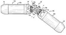
- the articulating joint 30includes a connecting member 60 connected to each of the repeater bodies 12 a , 12 b using gimbal connections 70 a , 70 b to allow angular deflection of the housings 42 a , 42 b in at least two directions.
- a first ring 71 a , 71 bis secured to each cone 44 at the end of the respective housings 42 a , 42 b and a second ring 73 a , 73 b is secured to the first ring 71 a , 71 b .
- Gimbal connection members 72 a , 72 bare pivotally coupled within the respective second rings 73 a , 73 b using coaxial pins 74 .
- the gimbal connection members 72 a , 72 bthus pivot with respect to the housings 42 a , 42 b about the axis Y-Y and the axis Y′-Y′ respectively.
- First and second connection end portions 62 a , 62 b of the connecting member 60are pivotally coupled to respective gimbal connection members 72 a , 72 b using pins 75 .
- the connecting member 60thereby pivots with respect to the first gimbal connection member 72 a about the axis X-X and pivots with respect to the second gimbal connection member 72 b about the axis X′-X′.
- FIG. 4depicts the X-X and X′-X′ axes in a direction into the paper (i.e., perpendicular to Y-Y and Y′-Y′ axes respectively).
- Each gimbal connection 70 a , 70 bthus provides two mutually perpendicular and intersecting axes of rotation.
- the gimbal connections 70 a , 70 balso incorporate torque restraints to prevent circumferential rotation, for example, about the longitudinal axes of the housings 42 a , 42 b .
- the flat sides of the connection end portions 62 a , 62 bare received between matching flats inside the gimbal connection members 72 a , 72 b to prevent circumferential rotation.
- connecting member 60can also be coupled using other types of gimbal or universal joint connections or any other type of connection providing the desired angular deflection.
- One embodiment of the connecting member 60has a “bar-bell” shape and includes a wider central portion 64 between the end portions 62 a , 62 b .
- a passageway 66extends through the “bar-bell” shaped connecting member 60 for receiving the pigtail connection, as described above.
- the wider central portion 64includes annular recesses 68 a , 68 b facing the respective connection end portions 62 a , 62 b .
- the wider central portion 64allows the “bar-bell” shaped connecting member 60 to be longer and allows for a greater deflection angle.
- the annular recesses 68 a , 68 breceive the rings 73 a , 73 b such that the central portion 64 acts as a stop block and rides on both of the rings 73 a , 73 b when the repeaters are at a maximum angular deflection.
- a “dog bone” shaped connecting member 80can be used in the articulating joint 30 shown in FIG. 4 .
- the “dog bone” shaped connecting member 80includes first and second connection ends 82 a , 82 b and a narrower neck 84 .
- the “dog bone” shaped connecting member 80also includes a passageway 86 extending therethrough for receiving the pigtail connection.
- the “dog bone” shaped connecting member 80is pivotally coupled to the housings 42 a , 42 b using the gimbal connections 70 a , 70 b in the same manner as the “bar-bell” shaped connecting member 60 described above.
- the “dog bone” shaped connecting member 80is lighter than the “bar bell” shaped connecting member 60 , but is also shorter and does not allow as much angular deflection.
- Connecting members having other shapescan also be used between the gimbal connections 70 a , 70 b in this embodiment of the articulating joint 30 .
- the articulating joint 30 ′includes a connecting member 90 that is pivotally coupled to each of the housings 42 a , 42 b about different perpendicular axes.
- the connecting member 90shown in greater detail in FIG. 8, includes first and second connections ends 92 a , 92 b with different perpendicular axes of rotation.
- the first connection end 92 ais pivotally coupled to the cone 44 on the first housing 42 a using coaxial pins 94 , such that the connecting member 90 pivots with respect to the first housing 42 a about an axis Y-Y.
- the second connection end 92 bis pivotally coupled to the cone 44 of the second housing 42 b such that the connecting member 90 pivots with respect to the second housing 42 b about the axis X-X.
- the axis X-Xis preferably substantially perpendicular to a plane containing the axis Y-Y but does not intersect the axis Y-Y.
- FIG. 9Another variation of the connecting member 90 ′ is shown in FIG. 9 .
- the connecting member 90 ′is pivotally coupled to the cones 44 of the housings 42 a , 42 b in the same manner as the connecting member 90 described above.
- Both of these connecting members 90 , 90 ′include a passageway 95 , 95 ′ for receiving the pigtail connection.
- the connecting members 90 , 90 ′are capable of providing the desired articulation, the “bar bell” shaped connecting member 60 and the “dog bone” shaped connecting member 80 may be preferred for purposes of manufacturing and assembly.
- FIG. 10A further embodiment of the articulating joint 30 ′′ is shown in FIG. 10 .
- the articulating joint 30 ′′includes first and second connecting members 100 , 102 , as shown in FIG. 11 .
- the first connecting member 100is pivotally coupled to the cone 44 of the first housing 42 a using coaxial pins 104 , such that the first connecting member 100 pivots with respect to the first housing 42 a about an axis Y-Y.
- the second connecting member 102is pivotally coupled to the cone 44 of the second housing 42 b such that the second connecting member 102 pivots with respect to the second housing 42 b about an axis Y′-Y′.
- the first and second connecting members 100 , 102are pivotally coupled together such that the first and second connecting members 100 , 102 pivot with respect to one another about an axis X-X.
- the axis X-Xis preferably substantially perpendicular to a plane containing the axis Y-Y and the axis Y′-Y′ but does not intersect the axes Y-Y and Y′-Y . This type of articulating joint thus provides angular deflection in at least two directions.
- Each of the articulating joints 30 , 30 ′, 30 ′′ in the embodiments described abovepreferably provides a deflection angle a that allows both repeater bodies 12 a , 12 b to simultaneously contact the cable drum surface 96 at locations 98 a , 98 b on the housings 42 a , 42 b (see FIG. 7 ).
- the housings 42 a , 42 bpreferably carry the load as opposed to the cones 44 .
- the deflection angle ⁇is about 36°. Based upon the sizes of the cable drums, the deflection angle a is typically less than about 50°, but deflection angles in excess of 50° can also be achieved.
- any number of housingscan be coupled together using any one of these embodiments of the articulating joint or, for that matter, any combination of these embodiments.
- the repeater systemcan be greatly expanded to amplify additional fibers when the capacity of the fiber optic cables is expanded further.
- the present inventioncan accommodate additional fibers using housings having essentially the same size and type as existing repeater housings, thereby avoiding the inconvenience associated with redesigning, manufacturing, testing, qualifying, storing, transporting, deploying and recovering larger repeater bodies in an undersea fiber optic system.
- the exemplary embodimentdescribes a repeater system for use with undersea fiber optic cables, the modular articulated housing system described above can be used to house any type of electronic equipment and with any type of cable.
Landscapes
- Physics & Mathematics (AREA)
- General Physics & Mathematics (AREA)
- Optics & Photonics (AREA)
- Cable Accessories (AREA)
Abstract
Description
Claims (22)
Priority Applications (1)
| Application Number | Priority Date | Filing Date | Title |
|---|---|---|---|
| US09/669,638US6571042B1 (en) | 2000-09-26 | 2000-09-26 | Multi-body modular repeater system and articulated housing for use therewith |
Applications Claiming Priority (1)
| Application Number | Priority Date | Filing Date | Title |
|---|---|---|---|
| US09/669,638US6571042B1 (en) | 2000-09-26 | 2000-09-26 | Multi-body modular repeater system and articulated housing for use therewith |
Publications (1)
| Publication Number | Publication Date |
|---|---|
| US6571042B1true US6571042B1 (en) | 2003-05-27 |
Family
ID=24687110
Family Applications (1)
| Application Number | Title | Priority Date | Filing Date |
|---|---|---|---|
| US09/669,638Expired - Fee RelatedUS6571042B1 (en) | 2000-09-26 | 2000-09-26 | Multi-body modular repeater system and articulated housing for use therewith |
Country Status (1)
| Country | Link |
|---|---|
| US (1) | US6571042B1 (en) |
Cited By (33)
| Publication number | Priority date | Publication date | Assignee | Title |
|---|---|---|---|---|
| US20040160663A1 (en)* | 2002-11-19 | 2004-08-19 | Red Sky Systems, Inc. | Optical amplifier module housed in a universal cable joint for an undersea optical transmission system |
| US20040196529A1 (en)* | 2002-12-13 | 2004-10-07 | Young Mark K. | Method and apparatus for electrically isolating an optical amplifier module housed in a universal cable joint |
| US20050105164A1 (en)* | 2003-11-17 | 2005-05-19 | Young Mark K. | Electrical insulating ring located between an end cap and a tension sleeve of an undersea pressure vessel housing an optical amplifier module |
| US20050179988A1 (en)* | 2002-12-13 | 2005-08-18 | Young Mark K. | Optical amplifier module housed in a factory cable joint |
| US20050185257A1 (en)* | 2003-11-17 | 2005-08-25 | Young Mark K. | Apparatus for concatonating a plurality of undersea pressure vessels each housing an optical amplifier module |
| US20050200943A1 (en)* | 2004-03-12 | 2005-09-15 | Devincentis David S. | Thermal management of an optical amplifier module housed in a universal cable joint |
| US20050251112A1 (en)* | 2003-05-23 | 2005-11-10 | Danitz David J | Articulating mechanism for remote manipulation of a surgical or diagnostic tool |
| US20050273084A1 (en)* | 2004-06-07 | 2005-12-08 | Novare Surgical Systems, Inc. | Link systems and articulation mechanisms for remote manipulation of surgical or diagnostic tools |
| US20050273085A1 (en)* | 2004-06-07 | 2005-12-08 | Novare Surgical Systems, Inc. | Articulating mechanism with flex-hinged links |
| US20060050541A1 (en)* | 2004-09-09 | 2006-03-09 | Terdan Dale R | Controlled inrush current limiter |
| US20060111615A1 (en)* | 2004-11-23 | 2006-05-25 | Novare Surgical Systems, Inc. | Articulating sheath for flexible instruments |
| US20060111209A1 (en)* | 2004-11-23 | 2006-05-25 | Novare Surgical Systems, Inc. | Articulating mechanisms and link systems with torque transmission in remote manipulation of instruments and tools |
| US20060111616A1 (en)* | 2004-11-24 | 2006-05-25 | Novare Surgical Systems, Inc. | Articulating mechanism components and system for easy assembly and disassembly |
| US7062143B1 (en) | 2005-04-28 | 2006-06-13 | International Business Machines Corporation | Modular mechanism for protecting fiber optic cables |
| US20070004241A1 (en)* | 2005-06-30 | 2007-01-04 | Meier Pascal C | High speed active flex cable link |
| US20070053645A1 (en)* | 2005-09-08 | 2007-03-08 | Kordahi Maurice E | Undersea equipment housing with molded terminations |
| US20070250113A1 (en)* | 2003-05-23 | 2007-10-25 | Hegeman David E | Tool with articulation lock |
| US20070287993A1 (en)* | 2006-06-13 | 2007-12-13 | Hinman Cameron D | Tool with rotation lock |
| US20080205823A1 (en)* | 2007-02-27 | 2008-08-28 | James Phillip Luther | Articulated force application for multi-fiber ferrules |
| US20080255421A1 (en)* | 2007-04-16 | 2008-10-16 | David Elias Hegeman | Articulating tool with improved tension member system |
| US20080255608A1 (en)* | 2007-04-16 | 2008-10-16 | Hinman Cameron D | Tool with end effector force limiter |
| US20080255588A1 (en)* | 2007-04-16 | 2008-10-16 | Hinman Cameron D | Tool with multi-state ratcheted end effector |
| US20080262538A1 (en)* | 2003-05-23 | 2008-10-23 | Novare Surgical Systems, Inc. | Articulating instrument |
| US7489438B1 (en) | 2003-11-17 | 2009-02-10 | Red Sky Subsea, Ltd. | Dielectric coating for an optical repeater pressure vessel |
| US20100041945A1 (en)* | 2008-08-18 | 2010-02-18 | Isbell Jr Lewis | Instrument with articulation lock |
| US9161771B2 (en) | 2011-05-13 | 2015-10-20 | Intuitive Surgical Operations Inc. | Medical instrument with snake wrist structure |
| US9221179B2 (en) | 2009-07-23 | 2015-12-29 | Intuitive Surgical Operations, Inc. | Articulating mechanism |
| WO2016128451A1 (en)* | 2015-02-10 | 2016-08-18 | Commscope Connectivity Uk Limited | Flexible cable interface device |
| CN110190497A (en)* | 2019-07-08 | 2019-08-30 | 江苏亨通海洋光网系统有限公司 | A Flexible and Scalable Submarine Cable Amplifier Structure |
| US10444438B2 (en)* | 2017-02-02 | 2019-10-15 | Ppc Broadband Fiber Ltd. | Optical fiber connector with articulating linkage that does not rotate |
| US11085798B2 (en) | 2018-08-07 | 2021-08-10 | Caterpillar Global Mining Europe Gmbh | System and method for monitoring fault conditions in a pan line of a longwall mining system |
| US11347004B2 (en)* | 2018-03-06 | 2022-05-31 | Neptune Subsea Ip Limited | Submarine optical system with free space optical add/drop multiplexer |
| US20230141958A1 (en)* | 2020-04-10 | 2023-05-11 | Omnisens Sa | Section and assembly comprising a plurality of such sections |
Citations (6)
| Publication number | Priority date | Publication date | Assignee | Title |
|---|---|---|---|---|
| US4757157A (en)* | 1986-11-14 | 1988-07-12 | Alcatel Cit | Housing for an undersea repeater |
| US4785139A (en) | 1986-05-30 | 1988-11-15 | American Telephone And Telegraph Company, At&T Bell Laboratories | Cable with flexible high pressure equipment enclosure material and method of constructing same |
| US5018980A (en)* | 1989-10-13 | 1991-05-28 | Robb John R | Snap-apart universal jointed electrical device |
| US5110224A (en) | 1989-11-15 | 1992-05-05 | Stc Plc | Flexible cable termination with swivel couplings |
| US5197817A (en)* | 1992-06-16 | 1993-03-30 | The United States Of America As Represented By The Administrator Of The National Aeronautics And Space Administration | Quick acting gimbal joint |
| JPH09258082A (en)* | 1996-03-18 | 1997-10-03 | Fujitsu Ltd | Optical submarine cable transmission system |
- 2000
- 2000-09-26USUS09/669,638patent/US6571042B1/ennot_activeExpired - Fee Related
Patent Citations (6)
| Publication number | Priority date | Publication date | Assignee | Title |
|---|---|---|---|---|
| US4785139A (en) | 1986-05-30 | 1988-11-15 | American Telephone And Telegraph Company, At&T Bell Laboratories | Cable with flexible high pressure equipment enclosure material and method of constructing same |
| US4757157A (en)* | 1986-11-14 | 1988-07-12 | Alcatel Cit | Housing for an undersea repeater |
| US5018980A (en)* | 1989-10-13 | 1991-05-28 | Robb John R | Snap-apart universal jointed electrical device |
| US5110224A (en) | 1989-11-15 | 1992-05-05 | Stc Plc | Flexible cable termination with swivel couplings |
| US5197817A (en)* | 1992-06-16 | 1993-03-30 | The United States Of America As Represented By The Administrator Of The National Aeronautics And Space Administration | Quick acting gimbal joint |
| JPH09258082A (en)* | 1996-03-18 | 1997-10-03 | Fujitsu Ltd | Optical submarine cable transmission system |
Cited By (103)
| Publication number | Priority date | Publication date | Assignee | Title |
|---|---|---|---|---|
| US20040160663A1 (en)* | 2002-11-19 | 2004-08-19 | Red Sky Systems, Inc. | Optical amplifier module housed in a universal cable joint for an undersea optical transmission system |
| US7529020B2 (en)* | 2002-11-19 | 2009-05-05 | Huawei Marine Networks Co., Ltd. | Optical amplifier module housed in a universal cable joint for an undersea optical transmission system |
| US20040196529A1 (en)* | 2002-12-13 | 2004-10-07 | Young Mark K. | Method and apparatus for electrically isolating an optical amplifier module housed in a universal cable joint |
| US6917465B2 (en)* | 2002-12-13 | 2005-07-12 | Red Sky Systems, Inc. | Method and apparatus for electrically isolating an optical amplifier module housed in a universal cable joint |
| US20050179988A1 (en)* | 2002-12-13 | 2005-08-18 | Young Mark K. | Optical amplifier module housed in a factory cable joint |
| US7436584B2 (en) | 2002-12-13 | 2008-10-14 | Red Sky Subsea, Ltd. | Optical amplifier module housed in a factory cable joint |
| US8535347B2 (en) | 2003-05-23 | 2013-09-17 | Intuitive Surgical Operations, Inc. | Articulating mechanisms with bifurcating control |
| US9085085B2 (en) | 2003-05-23 | 2015-07-21 | Intuitive Surgical Operations, Inc. | Articulating mechanisms with actuatable elements |
| US10342626B2 (en) | 2003-05-23 | 2019-07-09 | Intuitive Surgical Operations, Inc. | Surgical instrument |
| US7615066B2 (en) | 2003-05-23 | 2009-11-10 | Novare Surgical Systems, Inc. | Articulating mechanism for remote manipulation of a surgical or diagnostic tool |
| US20050251112A1 (en)* | 2003-05-23 | 2005-11-10 | Danitz David J | Articulating mechanism for remote manipulation of a surgical or diagnostic tool |
| US8100824B2 (en) | 2003-05-23 | 2012-01-24 | Intuitive Surgical Operations, Inc. | Tool with articulation lock |
| US9737365B2 (en) | 2003-05-23 | 2017-08-22 | Intuitive Surgical Operations, Inc. | Tool with articulation lock |
| US20100261971A1 (en)* | 2003-05-23 | 2010-10-14 | Danitz David J | Articulating retractors |
| US20060094931A1 (en)* | 2003-05-23 | 2006-05-04 | Novare Surgical Systems, Inc. | Articulating mechanism for remote manipulation of a surgical or diagnostic tool |
| US9440364B2 (en) | 2003-05-23 | 2016-09-13 | Intuitive Surgical Operations, Inc. | Articulating instrument |
| US9370868B2 (en) | 2003-05-23 | 2016-06-21 | Intuitive Surgical Operations, Inc. | Articulating endoscopes |
| US9434077B2 (en) | 2003-05-23 | 2016-09-06 | Intuitive Surgical Operations, Inc | Articulating catheters |
| US9498888B2 (en) | 2003-05-23 | 2016-11-22 | Intuitive Surgical Operations, Inc. | Articulating instrument |
| US20100262161A1 (en)* | 2003-05-23 | 2010-10-14 | Danitz David J | Articulating instruments with joystick control |
| US20100262180A1 (en)* | 2003-05-23 | 2010-10-14 | Danitz David J | Articulating mechanisms with bifurcating control |
| US7682307B2 (en) | 2003-05-23 | 2010-03-23 | Novare Surgical Systems, Inc. | Articulating mechanism for remote manipulation of a surgical or diagnostic tool |
| US9072427B2 (en) | 2003-05-23 | 2015-07-07 | Intuitive Surgical Operations, Inc. | Tool with articulation lock |
| US20070250113A1 (en)* | 2003-05-23 | 2007-10-25 | Hegeman David E | Tool with articulation lock |
| US10722314B2 (en) | 2003-05-23 | 2020-07-28 | Intuitive Surgical Operations, Inc. | Articulating retractors |
| US9550300B2 (en) | 2003-05-23 | 2017-01-24 | Intuitive Surgical Operations, Inc. | Articulating retractors |
| US20100262075A1 (en)* | 2003-05-23 | 2010-10-14 | Danitz David J | Articulating catheters |
| US20080262538A1 (en)* | 2003-05-23 | 2008-10-23 | Novare Surgical Systems, Inc. | Articulating instrument |
| US11547287B2 (en) | 2003-05-23 | 2023-01-10 | Intuitive Surgical Operations, Inc. | Surgical instrument |
| US20100261964A1 (en)* | 2003-05-23 | 2010-10-14 | Danitz David J | Articulating endoscopes |
| US20050185257A1 (en)* | 2003-11-17 | 2005-08-25 | Young Mark K. | Apparatus for concatonating a plurality of undersea pressure vessels each housing an optical amplifier module |
| US7489438B1 (en) | 2003-11-17 | 2009-02-10 | Red Sky Subsea, Ltd. | Dielectric coating for an optical repeater pressure vessel |
| US20050105164A1 (en)* | 2003-11-17 | 2005-05-19 | Young Mark K. | Electrical insulating ring located between an end cap and a tension sleeve of an undersea pressure vessel housing an optical amplifier module |
| US6950229B2 (en) | 2003-11-17 | 2005-09-27 | Red Sky Systems, Inc. | Electrical insulating ring located between an end cap and a tension sleeve of an undersea pressure vessel housing an optical amplifier module |
| WO2005083852A1 (en)* | 2004-02-23 | 2005-09-09 | Red Sky Systems, Inc. | An apparatus for concatonating a plurality of undersea pressure vessels each housing an optical amplifier module |
| US20050200943A1 (en)* | 2004-03-12 | 2005-09-15 | Devincentis David S. | Thermal management of an optical amplifier module housed in a universal cable joint |
| WO2005091445A1 (en)* | 2004-03-12 | 2005-09-29 | Red Sky Systems, Inc. | Thermal management of an optical amplifier module housed in a universal cable joint |
| US11491310B2 (en) | 2004-06-07 | 2022-11-08 | Intuitive Surgical Operations, Inc. | Articulating mechanism with flex-hinged links |
| US9095253B2 (en) | 2004-06-07 | 2015-08-04 | Intuitive Surgical Operations, Inc. | Articulating mechanism with flex hinged links |
| US8323297B2 (en) | 2004-06-07 | 2012-12-04 | Intuitive Surgical Operations, Inc. | Articulating mechanism with flex-hinged links |
| US20100234831A1 (en)* | 2004-06-07 | 2010-09-16 | Hinman Cameron D | Articulating mechanism with flex-hinged links |
| US20100249759A1 (en)* | 2004-06-07 | 2010-09-30 | Cameron Dale Hinman | Link systems and articulation mechanisms for remote manipulation of surgical of diagnostic tools |
| US10729885B2 (en) | 2004-06-07 | 2020-08-04 | Intuitive Surgical Operations, Inc. | Articulating mechanism with flex-hinged links |
| US8920429B2 (en) | 2004-06-07 | 2014-12-30 | Intuitive Surgical Operations, Inc. | Link systems and articulation mechanisms for remote manipulation of surgical or diagnostic tools |
| US7678117B2 (en) | 2004-06-07 | 2010-03-16 | Novare Surgical Systems, Inc. | Articulating mechanism with flex-hinged links |
| US9517326B2 (en) | 2004-06-07 | 2016-12-13 | Intuitive Surgical Operations, Inc. | Link systems and articulation mechanisms for remote manipulation of surgical or diagnostic tools |
| US9861786B2 (en) | 2004-06-07 | 2018-01-09 | Intuitive Surgical Operations, Inc. | Articulating mechanism with flex hinged links |
| US7828808B2 (en)* | 2004-06-07 | 2010-11-09 | Novare Surgical Systems, Inc. | Link systems and articulation mechanisms for remote manipulation of surgical or diagnostic tools |
| US20050273085A1 (en)* | 2004-06-07 | 2005-12-08 | Novare Surgical Systems, Inc. | Articulating mechanism with flex-hinged links |
| US8419747B2 (en) | 2004-06-07 | 2013-04-16 | Intuitive Surgical Operations, Inc. | Link systems and articulation mechanisms for remote manipulation of surgical or diagnostic tools |
| US20050273084A1 (en)* | 2004-06-07 | 2005-12-08 | Novare Surgical Systems, Inc. | Link systems and articulation mechanisms for remote manipulation of surgical or diagnostic tools |
| US20060050541A1 (en)* | 2004-09-09 | 2006-03-09 | Terdan Dale R | Controlled inrush current limiter |
| US20060111210A1 (en)* | 2004-11-23 | 2006-05-25 | Novare Surgical Systems, Inc. | Articulating mechanisms and link systems with torque transmission in remote manipulation of instruments and tools |
| US9155449B2 (en) | 2004-11-23 | 2015-10-13 | Intuitive Surgical Operations Inc. | Instrument systems and methods of use |
| US20110087071A1 (en)* | 2004-11-23 | 2011-04-14 | Intuitive Surgical Operations, Inc. | Articulation sheath for flexible instruments |
| US10321927B2 (en) | 2004-11-23 | 2019-06-18 | Intuitive Surgical Operations, Inc. | Articulating mechanisms and link systems with torque transmission in remote manipulation of instruments and tools |
| US7785252B2 (en) | 2004-11-23 | 2010-08-31 | Novare Surgical Systems, Inc. | Articulating sheath for flexible instruments |
| US9700334B2 (en) | 2004-11-23 | 2017-07-11 | Intuitive Surgical Operations, Inc. | Articulating mechanisms and link systems with torque transmission in remote manipulation of instruments and tools |
| US11638590B2 (en) | 2004-11-23 | 2023-05-02 | Intuitive Surgical Operations, Inc. | Articulating mechanisms and link systems with torque transmission in remote manipulation of instruments and tools |
| US20060111615A1 (en)* | 2004-11-23 | 2006-05-25 | Novare Surgical Systems, Inc. | Articulating sheath for flexible instruments |
| US20060111209A1 (en)* | 2004-11-23 | 2006-05-25 | Novare Surgical Systems, Inc. | Articulating mechanisms and link systems with torque transmission in remote manipulation of instruments and tools |
| US8277375B2 (en) | 2004-11-23 | 2012-10-02 | Intuitive Surgical Operations, Inc. | Flexible segment system |
| US8182417B2 (en) | 2004-11-24 | 2012-05-22 | Intuitive Surgical Operations, Inc. | Articulating mechanism components and system for easy assembly and disassembly |
| US20060111616A1 (en)* | 2004-11-24 | 2006-05-25 | Novare Surgical Systems, Inc. | Articulating mechanism components and system for easy assembly and disassembly |
| US7062143B1 (en) | 2005-04-28 | 2006-06-13 | International Business Machines Corporation | Modular mechanism for protecting fiber optic cables |
| US20070004241A1 (en)* | 2005-06-30 | 2007-01-04 | Meier Pascal C | High speed active flex cable link |
| US7371966B2 (en)* | 2005-06-30 | 2008-05-13 | Intel Corporation | High speed active flex cable link |
| US20070053645A1 (en)* | 2005-09-08 | 2007-03-08 | Kordahi Maurice E | Undersea equipment housing with molded terminations |
| US7278789B2 (en) | 2005-09-08 | 2007-10-09 | Tyco Telecommunications (Us) Inc. | Undersea equipment housing with molded terminations |
| US20070287993A1 (en)* | 2006-06-13 | 2007-12-13 | Hinman Cameron D | Tool with rotation lock |
| US9561045B2 (en) | 2006-06-13 | 2017-02-07 | Intuitive Surgical Operations, Inc. | Tool with rotation lock |
| US20080205823A1 (en)* | 2007-02-27 | 2008-08-28 | James Phillip Luther | Articulated force application for multi-fiber ferrules |
| US7540666B2 (en)* | 2007-02-27 | 2009-06-02 | Corning Cable Systems Llc | Articulated force application for multi-fiber ferrules |
| US20080255588A1 (en)* | 2007-04-16 | 2008-10-16 | Hinman Cameron D | Tool with multi-state ratcheted end effector |
| US8562640B2 (en) | 2007-04-16 | 2013-10-22 | Intuitive Surgical Operations, Inc. | Tool with multi-state ratcheted end effector |
| US8409244B2 (en) | 2007-04-16 | 2013-04-02 | Intuitive Surgical Operations, Inc. | Tool with end effector force limiter |
| US7862554B2 (en) | 2007-04-16 | 2011-01-04 | Intuitive Surgical Operations, Inc. | Articulating tool with improved tension member system |
| US20080255421A1 (en)* | 2007-04-16 | 2008-10-16 | David Elias Hegeman | Articulating tool with improved tension member system |
| US20080255608A1 (en)* | 2007-04-16 | 2008-10-16 | Hinman Cameron D | Tool with end effector force limiter |
| US9033960B2 (en) | 2008-08-18 | 2015-05-19 | Intuitive Surgical Operations, Inc. | Instrument with multiple articulation locks |
| US9737298B2 (en) | 2008-08-18 | 2017-08-22 | Intuitive Surgical Operations, Inc. | Instrument with articulation lock |
| US8465475B2 (en) | 2008-08-18 | 2013-06-18 | Intuitive Surgical Operations, Inc. | Instrument with multiple articulation locks |
| US11998195B2 (en) | 2008-08-18 | 2024-06-04 | Intuitive Surgical Operations, Inc. | Instrument with multiple articulation locks |
| US20100041945A1 (en)* | 2008-08-18 | 2010-02-18 | Isbell Jr Lewis | Instrument with articulation lock |
| US11234694B2 (en) | 2008-08-18 | 2022-02-01 | Intuitive Surgical Operations, Inc. | Instrument with multiple articulation locks |
| US9221179B2 (en) | 2009-07-23 | 2015-12-29 | Intuitive Surgical Operations, Inc. | Articulating mechanism |
| US11357526B2 (en) | 2011-05-13 | 2022-06-14 | Intuitive Surgical Operations, Inc. | Medical instrument with snake wrist structure |
| US10335177B2 (en) | 2011-05-13 | 2019-07-02 | Intuitive Surgical Operations, Inc. | Medical instrument with snake wrist structure |
| US9161771B2 (en) | 2011-05-13 | 2015-10-20 | Intuitive Surgical Operations Inc. | Medical instrument with snake wrist structure |
| WO2016128451A1 (en)* | 2015-02-10 | 2016-08-18 | Commscope Connectivity Uk Limited | Flexible cable interface device |
| US10302888B2 (en) | 2015-02-10 | 2019-05-28 | Commscope Connectivity Uk Limited | Flexible cable interface device |
| US10830957B2 (en) | 2017-02-02 | 2020-11-10 | Ppc Broadband Fiber Ltd. | Optical fiber connector with gimballed sub-assembly |
| US20220326448A1 (en)* | 2017-02-02 | 2022-10-13 | Ppc Broadband Fiber Ltd. | Optical fiber connector |
| EP3577505B1 (en)* | 2017-02-02 | 2022-05-11 | PPC Broadband Fiber Ltd. | Optical fiber connector |
| US12140805B2 (en)* | 2017-02-02 | 2024-11-12 | Ppc Broadband Fiber Ltd. | Optical fiber connector with articulated relative movement |
| US11372167B2 (en) | 2017-02-02 | 2022-06-28 | Ppc Broadband Fiber Ltd. | Optical fiber connector with articulating sleeve-carrier linkage |
| US10444438B2 (en)* | 2017-02-02 | 2019-10-15 | Ppc Broadband Fiber Ltd. | Optical fiber connector with articulating linkage that does not rotate |
| US11347004B2 (en)* | 2018-03-06 | 2022-05-31 | Neptune Subsea Ip Limited | Submarine optical system with free space optical add/drop multiplexer |
| US11085798B2 (en) | 2018-08-07 | 2021-08-10 | Caterpillar Global Mining Europe Gmbh | System and method for monitoring fault conditions in a pan line of a longwall mining system |
| CN110190497A (en)* | 2019-07-08 | 2019-08-30 | 江苏亨通海洋光网系统有限公司 | A Flexible and Scalable Submarine Cable Amplifier Structure |
| WO2021003804A1 (en)* | 2019-07-08 | 2021-01-14 | 江苏亨通海洋光网系统有限公司 | Flexible and expandable submarine cable amplifier structure |
| US20230141958A1 (en)* | 2020-04-10 | 2023-05-11 | Omnisens Sa | Section and assembly comprising a plurality of such sections |
| US11867954B2 (en)* | 2020-04-10 | 2024-01-09 | Omnisens Sa | Section and assembly comprising a plurality of such sections |
Similar Documents
| Publication | Publication Date | Title |
|---|---|---|
| US6571042B1 (en) | Multi-body modular repeater system and articulated housing for use therewith | |
| JPH03212113A (en) | flexible cable termination | |
| US7572063B2 (en) | Opto-electric connector | |
| US5809187A (en) | Multi-port network using passive optical couplers | |
| CN101107551A (en) | Optical polarity module and system | |
| US4603942A (en) | Flexible, dielectric millimeter waveguide | |
| US6039081A (en) | Articulated bend limiter | |
| US6684005B1 (en) | Connection of an add/drop node | |
| US6424761B1 (en) | Cable repeater connecting joint | |
| US4717229A (en) | Bi-directional optical fiber coupler | |
| US6490066B1 (en) | Laser/microwave dual mode communications system | |
| US6290399B1 (en) | Optical submarine branching unit | |
| US20060064829A1 (en) | Pipeline pig | |
| JP2008516274A (en) | Optical fiber connector | |
| CA2557434C (en) | Undersea equipment housing with molded terminations | |
| US5335304A (en) | Connector distribution assembly for a fiber optic detector system | |
| US4690491A (en) | Building data transmission system | |
| CN201083858Y (en) | Flexible metal optical fiber line movable connector | |
| US11422312B2 (en) | Fiber optic converter | |
| EP4095578A1 (en) | Fiber optic split and quick connecting device for submarine cables | |
| JPS634163Y2 (en) | ||
| JPH11160542A (en) | Optical fiber wiring unit | |
| US5367592A (en) | Connector for optical fibres | |
| US7151867B2 (en) | Optical coupler having protective sheath | |
| JPS6035885B2 (en) | Submarine optical fiber cable retaining device |
Legal Events
| Date | Code | Title | Description |
|---|---|---|---|
| AS | Assignment | Owner name:TYCOM (US) INC., NEW JERSEY Free format text:ASSIGNMENT OF ASSIGNORS INTEREST;ASSIGNOR:KORDAHI, MAURICE;REEL/FRAME:011222/0769 Effective date:20000926 | |
| AS | Assignment | Owner name:TYCO TELECOMMUNICATIONS (US) INC., NEW JERSEY Free format text:ASSIGNMENT OF ASSIGNORS INTEREST;ASSIGNOR:TYCOM (US) INC.;REEL/FRAME:013906/0399 Effective date:20020102 | |
| FEPP | Fee payment procedure | Free format text:PAYOR NUMBER ASSIGNED (ORIGINAL EVENT CODE: ASPN); ENTITY STATUS OF PATENT OWNER: LARGE ENTITY | |
| FPAY | Fee payment | Year of fee payment:4 | |
| AS | Assignment | Owner name:TYCO ELECTRONICS SUBSEA COMMUNICATIONS LLC,NEW JER Free format text:CHANGE OF NAME;ASSIGNOR:TYCO TELECOMMUNICATIONS (US) INC.;REEL/FRAME:024213/0531 Effective date:20091228 Owner name:TYCO ELECTRONICS SUBSEA COMMUNICATIONS LLC, NEW JE Free format text:CHANGE OF NAME;ASSIGNOR:TYCO TELECOMMUNICATIONS (US) INC.;REEL/FRAME:024213/0531 Effective date:20091228 | |
| FPAY | Fee payment | Year of fee payment:8 | |
| REMI | Maintenance fee reminder mailed | ||
| LAPS | Lapse for failure to pay maintenance fees | ||
| STCH | Information on status: patent discontinuation | Free format text:PATENT EXPIRED DUE TO NONPAYMENT OF MAINTENANCE FEES UNDER 37 CFR 1.362 | |
| FP | Lapsed due to failure to pay maintenance fee | Effective date:20150527 |