US6570864B1 - Integrated receiving apparatus of subtractive interference cancellation receiver and adaptive MMSE receiver - Google Patents
Integrated receiving apparatus of subtractive interference cancellation receiver and adaptive MMSE receiverDownload PDFInfo
- Publication number
- US6570864B1 US6570864B1US09/441,611US44161199AUS6570864B1US 6570864 B1US6570864 B1US 6570864B1US 44161199 AUS44161199 AUS 44161199AUS 6570864 B1US6570864 B1US 6570864B1
- Authority
- US
- United States
- Prior art keywords
- signal
- indicates
- receiving
- interference
- tap weight
- Prior art date
- Legal status (The legal status is an assumption and is not a legal conclusion. Google has not performed a legal analysis and makes no representation as to the accuracy of the status listed.)
- Expired - Fee Related
Links
Images


Classifications
- H—ELECTRICITY
- H04—ELECTRIC COMMUNICATION TECHNIQUE
- H04B—TRANSMISSION
- H04B1/00—Details of transmission systems, not covered by a single one of groups H04B3/00 - H04B13/00; Details of transmission systems not characterised by the medium used for transmission
- H04B1/69—Spread spectrum techniques
- H04B1/707—Spread spectrum techniques using direct sequence modulation
- H04B1/7097—Interference-related aspects
- H04B1/7103—Interference-related aspects the interference being multiple access interference
- H04B1/7105—Joint detection techniques, e.g. linear detectors
- H04B1/71055—Joint detection techniques, e.g. linear detectors using minimum mean squared error [MMSE] detector
- H—ELECTRICITY
- H04—ELECTRIC COMMUNICATION TECHNIQUE
- H04B—TRANSMISSION
- H04B15/00—Suppression or limitation of noise or interference
- H—ELECTRICITY
- H04—ELECTRIC COMMUNICATION TECHNIQUE
- H04B—TRANSMISSION
- H04B2201/00—Indexing scheme relating to details of transmission systems not covered by a single group of H04B3/00 - H04B13/00
- H04B2201/69—Orthogonal indexing scheme relating to spread spectrum techniques in general
- H04B2201/707—Orthogonal indexing scheme relating to spread spectrum techniques in general relating to direct sequence modulation
- H04B2201/70701—Orthogonal indexing scheme relating to spread spectrum techniques in general relating to direct sequence modulation featuring pilot assisted reception
Definitions
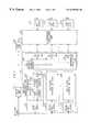
- FIG. 1is a block diagram illustrating an integrated receiver of a parallel multi-stage interference cancellation receiver and an adaptive MMSE receiver in accordance with one embodiment of the present invention
- the interference cancellation device 240includes an adding element 241 and adding elements 261 to 26 N.
- the adding element 241adds the interference signal regenerated by the interference regeneration devices 231 to 23 N to the receiving signal transmitted through the delay unit 211 .
- Adding elements 261 to 26 Nadd the interference signal regenerated by the interference regeneration devices 231 to 23 N to the added value through the adding element 241 .
- bit value determiner 133determines the extracted real value as “1” if the value is larger than “0”, otherwise, determines the extracted real value as “0”, then, restores the transmitted signal from the first user.
- a training data for a tap weightis generally needed in processing a receiving signal of an adaptive apparatus.
- the present inventionuses a pilot symbol transmitted from a sending apparatus as the training data of the tap weight, it need not make and provide another training data like a conventional signal processing apparatus for adaptive receiving system.
- the tap weight controlling part 170controls the tap weight to minimize the size of the error signal ⁇ tilde over (e) ⁇ (m) detected by the error calculating part 160 , provides it to the adaptive filtering part 110 .
- the present inventionemploys the constrained MMSE criterion expressed by equation (2) as adaptive algorithm of the adaptive filtering part 110 .
- the s 1indicates a spreading code vector
- the x (m)indicates an adaptive component of tap weight vector
- two vectorsare orthogonal.
Landscapes
- Engineering & Computer Science (AREA)
- Computer Networks & Wireless Communication (AREA)
- Signal Processing (AREA)
- Noise Elimination (AREA)
- Cable Transmission Systems, Equalization Of Radio And Reduction Of Echo (AREA)
Abstract
Description
Claims (22)
Applications Claiming Priority (2)
| Application Number | Priority Date | Filing Date | Title |
|---|---|---|---|
| KR1019980049110AKR100283379B1 (en) | 1998-11-16 | 1998-11-16 | Parallel Multistage Interference Cancellation |
| KR1998-49110 | 1998-11-16 |
Publications (1)
| Publication Number | Publication Date |
|---|---|
| US6570864B1true US6570864B1 (en) | 2003-05-27 |
Family
ID=19558540
Family Applications (1)
| Application Number | Title | Priority Date | Filing Date |
|---|---|---|---|
| US09/441,611Expired - Fee RelatedUS6570864B1 (en) | 1998-11-16 | 1999-11-16 | Integrated receiving apparatus of subtractive interference cancellation receiver and adaptive MMSE receiver |
Country Status (2)
| Country | Link |
|---|---|
| US (1) | US6570864B1 (en) |
| KR (1) | KR100283379B1 (en) |
Cited By (24)
| Publication number | Priority date | Publication date | Assignee | Title |
|---|---|---|---|---|
| US20020067761A1 (en)* | 2000-12-01 | 2002-06-06 | Ning Kong | Method and system for canceling multiple access interference in CDMA wireless communication system |
| US20020142725A1 (en)* | 2001-04-02 | 2002-10-03 | Motorola, Inc. | Active interference suppressor utilizing recombinant transmultiplexing |
| US20020181629A1 (en)* | 2001-06-01 | 2002-12-05 | Nec Corporation | Adaptive antenna reception apparatus |
| US20030002569A1 (en)* | 2001-03-14 | 2003-01-02 | Oates John H. | Wireless communication systems and methods for long-code communications for regenerative multiple user detection involving implicit waveform subtraction |
| US20030031232A1 (en)* | 2001-03-09 | 2003-02-13 | Qicai Shi | System for code division multi-access communication |
| US20030035469A1 (en)* | 2001-08-20 | 2003-02-20 | Frank Colin D. | Linear minimun mean square error equalization with interference cancellation for mobile communication forward links utilizing orthogonal codes covered by long pseudorandom spreading codes |
| US20030091100A1 (en)* | 2000-06-22 | 2003-05-15 | Hassan El Nahas El Homsi | Method and device for radio signal reception |
| US20030162573A1 (en)* | 2002-02-19 | 2003-08-28 | Jyhchau Horng | Down-link interference cancellation for high-data-rate channels in advanced digital wireless networks |
| US20030231702A1 (en)* | 2001-03-14 | 2003-12-18 | Oates John H. | Wireless communications systems and methods for cache enabled multiple processor based multiple user detection |
| US20040090906A1 (en)* | 2002-11-08 | 2004-05-13 | Shimon Moshavi | Reduced complexity MMSE multiuser detection for a multirate CDMA link |
| US20040151264A1 (en)* | 2003-02-01 | 2004-08-05 | Qualcomm Incorporated | Method and apparatus for automatic gain control of a multi-carrier signal in a communication receiver |
| US20040176051A1 (en)* | 2003-03-06 | 2004-09-09 | Papadimitriou Panayiotis D. | Method and apparatus for receiving a CDMA signal |
| US20040190601A1 (en)* | 2003-03-06 | 2004-09-30 | Papadimitriou Panayiotis D. | Method and apparatus for receiving a CDMA signal |
| US20040229615A1 (en)* | 2003-05-12 | 2004-11-18 | Avneesh Agrawal | Soft handoff with interference cancellation in a wireless frequency hopping communication system |
| US6952589B1 (en)* | 2000-10-11 | 2005-10-04 | Soma Networks, Inc. | Method, system and apparatus for improving reception in multiple access communication systems |
| US20060093019A1 (en)* | 2004-10-15 | 2006-05-04 | Broadcom Corporation | RF band clock spur harmonic canceller |
| US20090233556A1 (en)* | 2008-03-17 | 2009-09-17 | Samsung Electronics Co., Ltd. | Method and system for beamforming communication in high throughput wireless communication systems |
| US20090257393A1 (en)* | 2005-01-21 | 2009-10-15 | Qinghua Li | Techniques to manage channel prediction |
| US20100111141A1 (en)* | 1999-08-31 | 2010-05-06 | Broadcom Corporation | Cancellation of burst noise in a communication system with application to S-CDMA |
| US20100220824A1 (en)* | 2005-11-15 | 2010-09-02 | Tommy Guess | Iterative interference cancellation using mixed feedback weights and stabilizing step sizes |
| US20100323743A1 (en)* | 2009-06-17 | 2010-12-23 | Hong Xin George Huan | Thermal energy control in a mobile transceiver |
| US7876866B1 (en)* | 2005-01-27 | 2011-01-25 | Pmc-Sierra Us, Inc. | Data subset selection algorithm for reducing data-pattern autocorrelations |
| US20110237196A1 (en)* | 2007-08-13 | 2011-09-29 | Samsung Electronics Co., Ltd. | System and method for efficient transmit and receive beamforming protocol with heterogeneous antenna configuration |
| US8478204B2 (en) | 2008-07-14 | 2013-07-02 | Samsung Electronics Co., Ltd. | System and method for antenna training of beamforming vectors having reuse of directional information |
Families Citing this family (3)
| Publication number | Priority date | Publication date | Assignee | Title |
|---|---|---|---|---|
| KR100746070B1 (en)* | 2000-11-16 | 2007-08-06 | 엘지전자 주식회사 | Partial Parallel Interference Cancellation Method |
| KR100722126B1 (en)* | 2000-12-12 | 2007-05-25 | 주식회사 케이티 | Multi-Level Interference Cancellation Method for Multi-User Reception |
| KR100896442B1 (en) | 2005-12-23 | 2009-05-14 | 삼성전자주식회사 | Apparatus and Method for Eliminating Interference of Adjacent Cells in Broadband Wireless Communication Systems |
Citations (6)
| Publication number | Priority date | Publication date | Assignee | Title |
|---|---|---|---|---|
| US5343496A (en) | 1993-09-24 | 1994-08-30 | Bell Communications Research, Inc. | Interference suppression in CDMA systems |
| US5425059A (en) | 1992-07-31 | 1995-06-13 | Nec Corporation | Adaptive receiving apparatus for digital communication system |
| US5644592A (en) | 1995-04-24 | 1997-07-01 | California Institute Of Technology | Parallel interference cancellation for CDMA applications |
| US6002727A (en)* | 1996-10-18 | 1999-12-14 | Matsushita Electric Industrial Co., Ltd. | Interference signal cancellation system |
| US6172969B1 (en)* | 1997-01-31 | 2001-01-09 | Oki Electric Industry Co., Ltd. | CDMA receiver employing successive cancellation of training-signal interference |
| US6259688B1 (en)* | 1993-04-22 | 2001-07-10 | Interdigital Technology Corporation | Spread spectrum CDMA subtractive interference canceler system |
- 1998
- 1998-11-16KRKR1019980049110Apatent/KR100283379B1/ennot_activeExpired - Fee Related
- 1999
- 1999-11-16USUS09/441,611patent/US6570864B1/ennot_activeExpired - Fee Related
Patent Citations (6)
| Publication number | Priority date | Publication date | Assignee | Title |
|---|---|---|---|---|
| US5425059A (en) | 1992-07-31 | 1995-06-13 | Nec Corporation | Adaptive receiving apparatus for digital communication system |
| US6259688B1 (en)* | 1993-04-22 | 2001-07-10 | Interdigital Technology Corporation | Spread spectrum CDMA subtractive interference canceler system |
| US5343496A (en) | 1993-09-24 | 1994-08-30 | Bell Communications Research, Inc. | Interference suppression in CDMA systems |
| US5644592A (en) | 1995-04-24 | 1997-07-01 | California Institute Of Technology | Parallel interference cancellation for CDMA applications |
| US6002727A (en)* | 1996-10-18 | 1999-12-14 | Matsushita Electric Industrial Co., Ltd. | Interference signal cancellation system |
| US6172969B1 (en)* | 1997-01-31 | 2001-01-09 | Oki Electric Industry Co., Ltd. | CDMA receiver employing successive cancellation of training-signal interference |
Non-Patent Citations (3)
| Title |
|---|
| IEEE, A Modified MMSE Receiver for Detection of DS-CDMA Signals in Fading Channels, 1996, pp. 898-902. |
| IEEE, Improved Parallel Interference Cancellation for CDMA, 1998, pp. 258-268. |
| IEEE, Modified Adaptive LMMSE Receiver for DS-CDMA Systems in Fading Channels, 1997, pp. 554-558. |
Cited By (73)
| Publication number | Priority date | Publication date | Assignee | Title |
|---|---|---|---|---|
| US8411769B2 (en)* | 1999-08-31 | 2013-04-02 | Broadcom Corporation | Cancellation of burst noise in a communication system with application to S-CDMA |
| US20100111141A1 (en)* | 1999-08-31 | 2010-05-06 | Broadcom Corporation | Cancellation of burst noise in a communication system with application to S-CDMA |
| US7167529B2 (en)* | 2000-06-22 | 2007-01-23 | Nortel Networks Limited | Method and device for radio signal reception |
| US20030091100A1 (en)* | 2000-06-22 | 2003-05-15 | Hassan El Nahas El Homsi | Method and device for radio signal reception |
| US7421279B2 (en) | 2000-10-11 | 2008-09-02 | Soma Networks, Inc. | Method, system and apparatus for improving reception in multiple access communication systems |
| US20050233698A1 (en)* | 2000-10-11 | 2005-10-20 | Ramesh Mantha | Method, system and apparatus for improving reception in multiple access communication systems |
| US6952589B1 (en)* | 2000-10-11 | 2005-10-04 | Soma Networks, Inc. | Method, system and apparatus for improving reception in multiple access communication systems |
| US20020067761A1 (en)* | 2000-12-01 | 2002-06-06 | Ning Kong | Method and system for canceling multiple access interference in CDMA wireless communication system |
| US6882678B2 (en)* | 2000-12-01 | 2005-04-19 | Ning Kong | Method and system for canceling multiple access interference in CDMA wireless communication system |
| US6876692B2 (en)* | 2001-03-09 | 2005-04-05 | Motorola, Inc. | System for code division multi-access communication |
| US20030031232A1 (en)* | 2001-03-09 | 2003-02-13 | Qicai Shi | System for code division multi-access communication |
| US7110437B2 (en) | 2001-03-14 | 2006-09-19 | Mercury Computer Systems, Inc. | Wireless communications systems and methods for direct memory access and buffering of digital signals for multiple user detection |
| US7210062B2 (en) | 2001-03-14 | 2007-04-24 | Mercury Computer Systems, Inc. | Wireless communications systems and methods for nonvolatile storage of operating parameters for multiple processor based multiple user detection |
| US20030128739A1 (en)* | 2001-03-14 | 2003-07-10 | Oates John H. | Wireless communications systems and methods for multiple operating system multiple user detection |
| US7453922B2 (en)* | 2001-03-14 | 2008-11-18 | Mercury Computer Systems, Inc. | Wireless communication systems and methods for contiguously addressable memory enabled multiple processor based multiple user detection |
| US20030191887A1 (en)* | 2001-03-14 | 2003-10-09 | Oates John H. | Wireless communications systems and methods for direct memory access and buffering of digital signals for multiple user detection |
| US20030198197A1 (en)* | 2001-03-14 | 2003-10-23 | Oates John H. | Wireless communication systems and methods for contiguously addressable memory enabled multiple processor based multiple user detection |
| US20030202559A1 (en)* | 2001-03-14 | 2003-10-30 | Oates John H. | Wireless communications systems and methods for nonvolatile storage of operating parameters for multiple processor based multiple user detection |
| US20030231702A1 (en)* | 2001-03-14 | 2003-12-18 | Oates John H. | Wireless communications systems and methods for cache enabled multiple processor based multiple user detection |
| US20030002569A1 (en)* | 2001-03-14 | 2003-01-02 | Oates John H. | Wireless communication systems and methods for long-code communications for regenerative multiple user detection involving implicit waveform subtraction |
| US7376175B2 (en) | 2001-03-14 | 2008-05-20 | Mercury Computer Systems, Inc. | Wireless communications systems and methods for cache enabled multiple processor based multiple user detection |
| US7327780B2 (en) | 2001-03-14 | 2008-02-05 | Mercury Computer Systems, Inc. | Wireless communications systems and methods for multiple operating system multiple user detection |
| US7248623B2 (en) | 2001-03-14 | 2007-07-24 | Mercury Computer Systems, Inc. | Wireless communications systems and methods for short-code multiple user detection |
| US7218668B2 (en) | 2001-03-14 | 2007-05-15 | Mercury Computer Systems, Inc. | Wireless communications systems and methods for virtual user based multiple user detection utilizing vector processor generated mapped cross-correlation matrices |
| US20030099225A1 (en)* | 2001-03-14 | 2003-05-29 | Oates John H. | Wireless communication systems and methods for long-code communications for regenerative multiple user detection involving pre-maximal combination matched filter outputs |
| US20030099224A1 (en)* | 2001-03-14 | 2003-05-29 | Oates John H. | Wireless communications systems and methods for short-code multiple user detection |
| US20030091058A1 (en)* | 2001-03-14 | 2003-05-15 | Oates John H. | Wireless communications systems and methods for virtual user based multiple user detection utilizing vector processor generated mapped cross-correlation matrices |
| US20030091106A1 (en)* | 2001-03-14 | 2003-05-15 | Oates John H. | Load balancing computational methods in a short-code spread-spectrum communications system |
| US7203221B2 (en) | 2001-03-14 | 2007-04-10 | Mercury Computer Systems, Inc. | Load balancing computational methods in a short-code spread-spectrum communications system |
| US20030091102A1 (en)* | 2001-03-14 | 2003-05-15 | Oates John H. | Computational methods for use in a short-code spread-spectrum communications system |
| US7177344B2 (en)* | 2001-03-14 | 2007-02-13 | Mercury Computer Systems, Inc. | Wireless communication systems and methods for long-code communications for regenerative multiple user detection involving implicit waveform subtraction |
| US7164706B2 (en) | 2001-03-14 | 2007-01-16 | Mercury Computer Systems, Inc. | Computational methods for use in a short-code spread-spectrum communications system |
| US7139306B2 (en)* | 2001-03-14 | 2006-11-21 | Mercury Computer Systems, Inc. | Wireless communication systems and methods for long-code communications for regenerative multiple user detection involving pre-maximal combination matched filter outputs |
| US7099374B2 (en)* | 2001-03-14 | 2006-08-29 | Mercury Computer Systems, Inc. | Wireless communication systems and methods for long-code communications for regenerative multiple user detection involving matched-filter outputs |
| US20030076875A1 (en)* | 2001-03-14 | 2003-04-24 | Oates John H. | Hardware and software for performing computations in a short-code spread-spectrum communications system |
| US7110440B2 (en) | 2001-03-14 | 2006-09-19 | Mercury Computer Systems, Inc. | Wireless communications systems and methods for multiple processor based multiple user detection |
| US20020142725A1 (en)* | 2001-04-02 | 2002-10-03 | Motorola, Inc. | Active interference suppressor utilizing recombinant transmultiplexing |
| US6819911B2 (en)* | 2001-04-02 | 2004-11-16 | General Dynamics Decision Systems, Inc. | Active interference suppressor utilizing recombinant transmultiplexing |
| US7103120B2 (en)* | 2001-06-01 | 2006-09-05 | Nec Corporation | Adaptive antenna reception apparatus |
| US20020181629A1 (en)* | 2001-06-01 | 2002-12-05 | Nec Corporation | Adaptive antenna reception apparatus |
| US20030035469A1 (en)* | 2001-08-20 | 2003-02-20 | Frank Colin D. | Linear minimun mean square error equalization with interference cancellation for mobile communication forward links utilizing orthogonal codes covered by long pseudorandom spreading codes |
| US6956893B2 (en)* | 2001-08-20 | 2005-10-18 | Motorola, Inc. | Linear minimum mean square error equalization with interference cancellation for mobile communication forward links utilizing orthogonal codes covered by long pseudorandom spreading codes |
| US20030162573A1 (en)* | 2002-02-19 | 2003-08-28 | Jyhchau Horng | Down-link interference cancellation for high-data-rate channels in advanced digital wireless networks |
| US7333466B2 (en)* | 2002-11-08 | 2008-02-19 | Intel Corporation | Reduced complexity MMSE multiuser detection for a multirate CDMA link |
| US20040090906A1 (en)* | 2002-11-08 | 2004-05-13 | Shimon Moshavi | Reduced complexity MMSE multiuser detection for a multirate CDMA link |
| US7995684B2 (en)* | 2003-02-01 | 2011-08-09 | Qualcomm, Incorporated | Method and apparatus for automatic gain control of a multi-carrier signal in a communication receiver |
| US20040151264A1 (en)* | 2003-02-01 | 2004-08-05 | Qualcomm Incorporated | Method and apparatus for automatic gain control of a multi-carrier signal in a communication receiver |
| US7333575B2 (en)* | 2003-03-06 | 2008-02-19 | Nokia Corporation | Method and apparatus for receiving a CDMA signal |
| US20040190601A1 (en)* | 2003-03-06 | 2004-09-30 | Papadimitriou Panayiotis D. | Method and apparatus for receiving a CDMA signal |
| US7313168B2 (en)* | 2003-03-06 | 2007-12-25 | Nokia Corporation | Method and apparatus for receiving a CDMA signal |
| WO2004079932A3 (en)* | 2003-03-06 | 2006-08-17 | Nokia Corp | Method and apparatus for receiving a cdma signal |
| US20040176051A1 (en)* | 2003-03-06 | 2004-09-09 | Papadimitriou Panayiotis D. | Method and apparatus for receiving a CDMA signal |
| US20040229615A1 (en)* | 2003-05-12 | 2004-11-18 | Avneesh Agrawal | Soft handoff with interference cancellation in a wireless frequency hopping communication system |
| US20070165696A1 (en)* | 2003-05-12 | 2007-07-19 | Avneesh Agrawal | Soft handoff with interference cancellation in a wireless frequency hopping communication system |
| US8934516B2 (en) | 2003-05-12 | 2015-01-13 | Qualcomm Incorporated | Soft handoff with interference cancellation in a wireless frequency hopping communication system |
| WO2004102815A3 (en)* | 2003-05-12 | 2006-05-11 | Qualcomm Inc | Soft handoff with interference cancellation in a wireless frequency hopping communication system |
| US7254158B2 (en)* | 2003-05-12 | 2007-08-07 | Qualcomm Incorporated | Soft handoff with interference cancellation in a wireless frequency hopping communication system |
| US20060093019A1 (en)* | 2004-10-15 | 2006-05-04 | Broadcom Corporation | RF band clock spur harmonic canceller |
| US7924904B2 (en)* | 2004-10-15 | 2011-04-12 | Broadcom Corporation | RF band clock spur harmonic canceller |
| US8442458B2 (en) | 2005-01-21 | 2013-05-14 | Intel Corporation | Techniques for beamforming using predicted channel state information |
| US20110032893A1 (en)* | 2005-01-21 | 2011-02-10 | Qinghua Li | Techniques to manage channel prediction |
| US20090257393A1 (en)* | 2005-01-21 | 2009-10-15 | Qinghua Li | Techniques to manage channel prediction |
| US8396029B2 (en)* | 2005-01-21 | 2013-03-12 | Intel Corporation | Techniques to manage channel prediction |
| US7876866B1 (en)* | 2005-01-27 | 2011-01-25 | Pmc-Sierra Us, Inc. | Data subset selection algorithm for reducing data-pattern autocorrelations |
| US20100220824A1 (en)* | 2005-11-15 | 2010-09-02 | Tommy Guess | Iterative interference cancellation using mixed feedback weights and stabilizing step sizes |
| US8300745B2 (en)* | 2005-11-15 | 2012-10-30 | Rambus Inc. | Iterative interference cancellation using mixed feedback weights and stabilizing step sizes |
| US20110237196A1 (en)* | 2007-08-13 | 2011-09-29 | Samsung Electronics Co., Ltd. | System and method for efficient transmit and receive beamforming protocol with heterogeneous antenna configuration |
| US8249513B2 (en) | 2007-08-13 | 2012-08-21 | Samsung Electronics Co., Ltd. | System and method for training different types of directional antennas that adapts the training sequence length to the number of antennas |
| US8917208B2 (en) | 2007-08-13 | 2014-12-23 | Samsung Electronics Co., Ltd. | System and method for efficient transmit and receive beamforming protocol with heterogeneous antenna configuration |
| US8417191B2 (en)* | 2008-03-17 | 2013-04-09 | Samsung Electronics Co., Ltd. | Method and system for beamforming communication in high throughput wireless communication systems |
| US20090233556A1 (en)* | 2008-03-17 | 2009-09-17 | Samsung Electronics Co., Ltd. | Method and system for beamforming communication in high throughput wireless communication systems |
| US8478204B2 (en) | 2008-07-14 | 2013-07-02 | Samsung Electronics Co., Ltd. | System and method for antenna training of beamforming vectors having reuse of directional information |
| US20100323743A1 (en)* | 2009-06-17 | 2010-12-23 | Hong Xin George Huan | Thermal energy control in a mobile transceiver |
Also Published As
| Publication number | Publication date |
|---|---|
| KR100283379B1 (en) | 2001-03-02 |
| KR20000032605A (en) | 2000-06-15 |
Similar Documents
| Publication | Publication Date | Title |
|---|---|---|
| US6570864B1 (en) | Integrated receiving apparatus of subtractive interference cancellation receiver and adaptive MMSE receiver | |
| CN100559700C (en) | Group successive interference cancellation with receive diversity block transmission | |
| JP4335911B2 (en) | Method for receiving a signal in a radio communication system and radio transceiver unit | |
| KR100842893B1 (en) | Iterative and turbobased method and apparatus for equalization of spreadspectrum downlink channels | |
| US6240099B1 (en) | Multi-user code division multiple access receiver | |
| JP3210343B2 (en) | Method and apparatus for receiving and decoding communication signals in a CDMA receiver | |
| JP5412657B2 (en) | Receiver with chip level equalization | |
| KR20020038962A (en) | Receiver for multiuser detection of cdma signals | |
| KR20110018143A (en) | Equalizer receiver in communication system and therfore method | |
| KR20080050205A (en) | Iterative reception method and iterative receiver | |
| JP2003152591A (en) | Multiple-user cdma wireless communication system | |
| JP4205761B2 (en) | Interference cancellation method and receiver | |
| EP1304815A2 (en) | A code division multiple access downlink receiver | |
| US6570863B1 (en) | Apparatus and method for adaptive CDMA detection based on constrained minimum mean squared error criterion | |
| Jeon et al. | The blind widely linear minimum output energy algorithm for DS-CDMA systems | |
| CN103139118A (en) | Amplitude estimation method, and interference elimination method and device for data link transmission | |
| KR20130075888A (en) | Equalizer receiver and operating method in wireless communication system | |
| JP4216256B2 (en) | Adaptive multi-user interference canceller and multi-user detector | |
| Kaur et al. | A dynamic successive interference cancellation (Dsic) scheme for latency reduction in Mc-Cdma multiuser detection | |
| KR100843252B1 (en) | Iterative reception method and Iterative receiver | |
| WO2005076831A2 (en) | Wireless communication method and apparatus for performing multi-user detection using reduced length channel impulse responses | |
| Aue | Optimum linear single user detection in direct-sequence spread-spectrum multiple access systems | |
| Sreesudha | Design of Interference cancellation Receiver for CDMA with MIMO system | |
| Bar-Ness | The Bootstrap Decorrelating Algorithm: A Promising Tool for Adaptive Separation of Multi-User CDMA Signals | |
| Karlsson et al. | Improved single-user detector for WCDMA systems based on Griffiths' algorithm |
Legal Events
| Date | Code | Title | Description |
|---|---|---|---|
| AS | Assignment | Owner name:KOREA TELECOM, KOREA, REPUBLIC OF Free format text:ASSIGNMENT OF ASSIGNORS INTEREST;ASSIGNORS:KIM, SEONG-RAG;JEONG, YOUNG-GYUN;PARK, NAM-JIN;AND OTHERS;REEL/FRAME:010407/0608 Effective date:19991112 Owner name:ELECTRONICS AND TELECOMMUNICATIONS RESEARCH INSTIT Free format text:ASSIGNMENT OF ASSIGNORS INTEREST;ASSIGNORS:KIM, SEONG-RAG;JEONG, YOUNG-GYUN;PARK, NAM-JIN;AND OTHERS;REEL/FRAME:010407/0608 Effective date:19991112 | |
| AS | Assignment | Owner name:ELECTRONICS AND TELECOMMUNICATIONS RESEARCH INSTIT Free format text:ASSIGNMENT OF ASSIGNORS INTEREST;ASSIGNORS:KIM, SEONG-RAG;JEONG, YOUNG-GYUN;PARK, NAM-JIN;AND OTHERS;REEL/FRAME:011321/0394 Effective date:20000630 | |
| FEPP | Fee payment procedure | Free format text:PAYOR NUMBER ASSIGNED (ORIGINAL EVENT CODE: ASPN); ENTITY STATUS OF PATENT OWNER: LARGE ENTITY | |
| FEPP | Fee payment procedure | Free format text:PAT HOLDER CLAIMS SMALL ENTITY STATUS, ENTITY STATUS SET TO SMALL (ORIGINAL EVENT CODE: LTOS); ENTITY STATUS OF PATENT OWNER: LARGE ENTITY | |
| REFU | Refund | Free format text:REFUND - PAYMENT OF MAINTENANCE FEE, 4TH YEAR, LARGE ENTITY (ORIGINAL EVENT CODE: R1551); ENTITY STATUS OF PATENT OWNER: LARGE ENTITY | |
| FPAY | Fee payment | Year of fee payment:4 | |
| FEPP | Fee payment procedure | Free format text:PAYOR NUMBER ASSIGNED (ORIGINAL EVENT CODE: ASPN); ENTITY STATUS OF PATENT OWNER: LARGE ENTITY Free format text:PAYER NUMBER DE-ASSIGNED (ORIGINAL EVENT CODE: RMPN); ENTITY STATUS OF PATENT OWNER: LARGE ENTITY | |
| FEPP | Fee payment procedure | Free format text:PAT HOLDER NO LONGER CLAIMS SMALL ENTITY STATUS, ENTITY STATUS SET TO UNDISCOUNTED (ORIGINAL EVENT CODE: STOL); ENTITY STATUS OF PATENT OWNER: LARGE ENTITY | |
| FPAY | Fee payment | Year of fee payment:8 | |
| AS | Assignment | Owner name:INTELLECTUAL DISCOVERY CO., LTD., KOREA, REPUBLIC Free format text:ACKNOWLEDGEMENT OF PATENT EXCLUSIVE LICENSE AGREEMENT;ASSIGNOR:ELECTRONICS AND TELECOMMUNICATIONS RESEARCH INSTITUTE;REEL/FRAME:031615/0770 Effective date:20130716 | |
| REMI | Maintenance fee reminder mailed | ||
| LAPS | Lapse for failure to pay maintenance fees | ||
| STCH | Information on status: patent discontinuation | Free format text:PATENT EXPIRED DUE TO NONPAYMENT OF MAINTENANCE FEES UNDER 37 CFR 1.362 | |
| FP | Lapsed due to failure to pay maintenance fee | Effective date:20150527 |