US6569753B1 - Collar positionable about a periphery of a contact pad and around a conductive structure secured to the contact pads, semiconductor device components including same, and methods for fabricating same - Google Patents
Collar positionable about a periphery of a contact pad and around a conductive structure secured to the contact pads, semiconductor device components including same, and methods for fabricating sameDownload PDFInfo
- Publication number
- US6569753B1 US6569753B1US09/590,418US59041800AUS6569753B1US 6569753 B1US6569753 B1US 6569753B1US 59041800 AUS59041800 AUS 59041800AUS 6569753 B1US6569753 B1US 6569753B1
- Authority
- US
- United States
- Prior art keywords
- collar
- conductive structure
- substrate
- disposing
- contact pad
- Prior art date
- Legal status (The legal status is an assumption and is not a legal conclusion. Google has not performed a legal analysis and makes no representation as to the accuracy of the status listed.)
- Expired - Lifetime, expires
Links
Images


Classifications
- H—ELECTRICITY
- H01—ELECTRIC ELEMENTS
- H01L—SEMICONDUCTOR DEVICES NOT COVERED BY CLASS H10
- H01L21/00—Processes or apparatus adapted for the manufacture or treatment of semiconductor or solid state devices or of parts thereof
- H01L21/02—Manufacture or treatment of semiconductor devices or of parts thereof
- H01L21/04—Manufacture or treatment of semiconductor devices or of parts thereof the devices having potential barriers, e.g. a PN junction, depletion layer or carrier concentration layer
- H01L21/34—Manufacture or treatment of semiconductor devices or of parts thereof the devices having potential barriers, e.g. a PN junction, depletion layer or carrier concentration layer the devices having semiconductor bodies not provided for in groups H01L21/18, H10D48/04 and H10D48/07, with or without impurities, e.g. doping materials
- H01L21/44—Manufacture of electrodes on semiconductor bodies using processes or apparatus not provided for in groups H01L21/38 - H01L21/428
- B—PERFORMING OPERATIONS; TRANSPORTING
- B33—ADDITIVE MANUFACTURING TECHNOLOGY
- B33Y—ADDITIVE MANUFACTURING, i.e. MANUFACTURING OF THREE-DIMENSIONAL [3-D] OBJECTS BY ADDITIVE DEPOSITION, ADDITIVE AGGLOMERATION OR ADDITIVE LAYERING, e.g. BY 3-D PRINTING, STEREOLITHOGRAPHY OR SELECTIVE LASER SINTERING
- B33Y10/00—Processes of additive manufacturing
- B—PERFORMING OPERATIONS; TRANSPORTING
- B33—ADDITIVE MANUFACTURING TECHNOLOGY
- B33Y—ADDITIVE MANUFACTURING, i.e. MANUFACTURING OF THREE-DIMENSIONAL [3-D] OBJECTS BY ADDITIVE DEPOSITION, ADDITIVE AGGLOMERATION OR ADDITIVE LAYERING, e.g. BY 3-D PRINTING, STEREOLITHOGRAPHY OR SELECTIVE LASER SINTERING
- B33Y80/00—Products made by additive manufacturing
- H—ELECTRICITY
- H01—ELECTRIC ELEMENTS
- H01L—SEMICONDUCTOR DEVICES NOT COVERED BY CLASS H10
- H01L24/00—Arrangements for connecting or disconnecting semiconductor or solid-state bodies; Methods or apparatus related thereto
- H01L24/01—Means for bonding being attached to, or being formed on, the surface to be connected, e.g. chip-to-package, die-attach, "first-level" interconnects; Manufacturing methods related thereto
- H01L24/10—Bump connectors ; Manufacturing methods related thereto
- H01L24/11—Manufacturing methods
- H—ELECTRICITY
- H01—ELECTRIC ELEMENTS
- H01L—SEMICONDUCTOR DEVICES NOT COVERED BY CLASS H10
- H01L24/00—Arrangements for connecting or disconnecting semiconductor or solid-state bodies; Methods or apparatus related thereto
- H01L24/01—Means for bonding being attached to, or being formed on, the surface to be connected, e.g. chip-to-package, die-attach, "first-level" interconnects; Manufacturing methods related thereto
- H01L24/10—Bump connectors ; Manufacturing methods related thereto
- H01L24/12—Structure, shape, material or disposition of the bump connectors prior to the connecting process
- H—ELECTRICITY
- H01—ELECTRIC ELEMENTS
- H01L—SEMICONDUCTOR DEVICES NOT COVERED BY CLASS H10
- H01L24/00—Arrangements for connecting or disconnecting semiconductor or solid-state bodies; Methods or apparatus related thereto
- H01L24/01—Means for bonding being attached to, or being formed on, the surface to be connected, e.g. chip-to-package, die-attach, "first-level" interconnects; Manufacturing methods related thereto
- H01L24/10—Bump connectors ; Manufacturing methods related thereto
- H01L24/15—Structure, shape, material or disposition of the bump connectors after the connecting process
- H01L24/16—Structure, shape, material or disposition of the bump connectors after the connecting process of an individual bump connector
- H—ELECTRICITY
- H01—ELECTRIC ELEMENTS
- H01L—SEMICONDUCTOR DEVICES NOT COVERED BY CLASS H10
- H01L24/00—Arrangements for connecting or disconnecting semiconductor or solid-state bodies; Methods or apparatus related thereto
- H01L24/74—Apparatus for manufacturing arrangements for connecting or disconnecting semiconductor or solid-state bodies
- H01L24/741—Apparatus for manufacturing means for bonding, e.g. connectors
- H01L24/742—Apparatus for manufacturing bump connectors
- H—ELECTRICITY
- H01—ELECTRIC ELEMENTS
- H01L—SEMICONDUCTOR DEVICES NOT COVERED BY CLASS H10
- H01L24/00—Arrangements for connecting or disconnecting semiconductor or solid-state bodies; Methods or apparatus related thereto
- H01L24/74—Apparatus for manufacturing arrangements for connecting or disconnecting semiconductor or solid-state bodies
- H01L24/75—Apparatus for connecting with bump connectors or layer connectors
- H—ELECTRICITY
- H01—ELECTRIC ELEMENTS
- H01L—SEMICONDUCTOR DEVICES NOT COVERED BY CLASS H10
- H01L24/00—Arrangements for connecting or disconnecting semiconductor or solid-state bodies; Methods or apparatus related thereto
- H01L24/80—Methods for connecting semiconductor or other solid state bodies using means for bonding being attached to, or being formed on, the surface to be connected
- H01L24/81—Methods for connecting semiconductor or other solid state bodies using means for bonding being attached to, or being formed on, the surface to be connected using a bump connector
- H—ELECTRICITY
- H05—ELECTRIC TECHNIQUES NOT OTHERWISE PROVIDED FOR
- H05K—PRINTED CIRCUITS; CASINGS OR CONSTRUCTIONAL DETAILS OF ELECTRIC APPARATUS; MANUFACTURE OF ASSEMBLAGES OF ELECTRICAL COMPONENTS
- H05K3/00—Apparatus or processes for manufacturing printed circuits
- H05K3/30—Assembling printed circuits with electric components, e.g. with resistor
- H05K3/32—Assembling printed circuits with electric components, e.g. with resistor electrically connecting electric components or wires to printed circuits
- H05K3/34—Assembling printed circuits with electric components, e.g. with resistor electrically connecting electric components or wires to printed circuits by soldering
- H05K3/341—Surface mounted components
- H05K3/3431—Leadless components
- H05K3/3436—Leadless components having an array of bottom contacts, e.g. pad grid array or ball grid array components
- H—ELECTRICITY
- H01—ELECTRIC ELEMENTS
- H01L—SEMICONDUCTOR DEVICES NOT COVERED BY CLASS H10
- H01L2224/00—Indexing scheme for arrangements for connecting or disconnecting semiconductor or solid-state bodies and methods related thereto as covered by H01L24/00
- H01L2224/01—Means for bonding being attached to, or being formed on, the surface to be connected, e.g. chip-to-package, die-attach, "first-level" interconnects; Manufacturing methods related thereto
- H01L2224/02—Bonding areas; Manufacturing methods related thereto
- H01L2224/04—Structure, shape, material or disposition of the bonding areas prior to the connecting process
- H01L2224/0401—Bonding areas specifically adapted for bump connectors, e.g. under bump metallisation [UBM]
- H—ELECTRICITY
- H01—ELECTRIC ELEMENTS
- H01L—SEMICONDUCTOR DEVICES NOT COVERED BY CLASS H10
- H01L2224/00—Indexing scheme for arrangements for connecting or disconnecting semiconductor or solid-state bodies and methods related thereto as covered by H01L24/00
- H01L2224/01—Means for bonding being attached to, or being formed on, the surface to be connected, e.g. chip-to-package, die-attach, "first-level" interconnects; Manufacturing methods related thereto
- H01L2224/02—Bonding areas; Manufacturing methods related thereto
- H01L2224/04—Structure, shape, material or disposition of the bonding areas prior to the connecting process
- H01L2224/05—Structure, shape, material or disposition of the bonding areas prior to the connecting process of an individual bonding area
- H01L2224/0554—External layer
- H01L2224/0556—Disposition
- H01L2224/05571—Disposition the external layer being disposed in a recess of the surface
- H01L2224/05572—Disposition the external layer being disposed in a recess of the surface the external layer extending out of an opening
- H—ELECTRICITY
- H01—ELECTRIC ELEMENTS
- H01L—SEMICONDUCTOR DEVICES NOT COVERED BY CLASS H10
- H01L2224/00—Indexing scheme for arrangements for connecting or disconnecting semiconductor or solid-state bodies and methods related thereto as covered by H01L24/00
- H01L2224/01—Means for bonding being attached to, or being formed on, the surface to be connected, e.g. chip-to-package, die-attach, "first-level" interconnects; Manufacturing methods related thereto
- H01L2224/02—Bonding areas; Manufacturing methods related thereto
- H01L2224/04—Structure, shape, material or disposition of the bonding areas prior to the connecting process
- H01L2224/06—Structure, shape, material or disposition of the bonding areas prior to the connecting process of a plurality of bonding areas
- H01L2224/061—Disposition
- H01L2224/0612—Layout
- H01L2224/0613—Square or rectangular array
- H01L2224/06131—Square or rectangular array being uniform, i.e. having a uniform pitch across the array
- H—ELECTRICITY
- H01—ELECTRIC ELEMENTS
- H01L—SEMICONDUCTOR DEVICES NOT COVERED BY CLASS H10
- H01L2224/00—Indexing scheme for arrangements for connecting or disconnecting semiconductor or solid-state bodies and methods related thereto as covered by H01L24/00
- H01L2224/01—Means for bonding being attached to, or being formed on, the surface to be connected, e.g. chip-to-package, die-attach, "first-level" interconnects; Manufacturing methods related thereto
- H01L2224/02—Bonding areas; Manufacturing methods related thereto
- H01L2224/04—Structure, shape, material or disposition of the bonding areas prior to the connecting process
- H01L2224/06—Structure, shape, material or disposition of the bonding areas prior to the connecting process of a plurality of bonding areas
- H01L2224/061—Disposition
- H01L2224/0612—Layout
- H01L2224/0615—Mirror array, i.e. array having only a reflection symmetry, i.e. bilateral symmetry
- H—ELECTRICITY
- H01—ELECTRIC ELEMENTS
- H01L—SEMICONDUCTOR DEVICES NOT COVERED BY CLASS H10
- H01L2224/00—Indexing scheme for arrangements for connecting or disconnecting semiconductor or solid-state bodies and methods related thereto as covered by H01L24/00
- H01L2224/01—Means for bonding being attached to, or being formed on, the surface to be connected, e.g. chip-to-package, die-attach, "first-level" interconnects; Manufacturing methods related thereto
- H01L2224/10—Bump connectors; Manufacturing methods related thereto
- H01L2224/1012—Auxiliary members for bump connectors, e.g. spacers
- H01L2224/10122—Auxiliary members for bump connectors, e.g. spacers being formed on the semiconductor or solid-state body to be connected
- H01L2224/10125—Reinforcing structures
- H01L2224/10126—Bump collar
- H—ELECTRICITY
- H01—ELECTRIC ELEMENTS
- H01L—SEMICONDUCTOR DEVICES NOT COVERED BY CLASS H10
- H01L2224/00—Indexing scheme for arrangements for connecting or disconnecting semiconductor or solid-state bodies and methods related thereto as covered by H01L24/00
- H01L2224/01—Means for bonding being attached to, or being formed on, the surface to be connected, e.g. chip-to-package, die-attach, "first-level" interconnects; Manufacturing methods related thereto
- H01L2224/10—Bump connectors; Manufacturing methods related thereto
- H01L2224/11—Manufacturing methods
- H01L2224/1147—Manufacturing methods using a lift-off mask
- H01L2224/1148—Permanent masks, i.e. masks left in the finished device, e.g. passivation layers
- H—ELECTRICITY
- H01—ELECTRIC ELEMENTS
- H01L—SEMICONDUCTOR DEVICES NOT COVERED BY CLASS H10
- H01L2224/00—Indexing scheme for arrangements for connecting or disconnecting semiconductor or solid-state bodies and methods related thereto as covered by H01L24/00
- H01L2224/01—Means for bonding being attached to, or being formed on, the surface to be connected, e.g. chip-to-package, die-attach, "first-level" interconnects; Manufacturing methods related thereto
- H01L2224/10—Bump connectors; Manufacturing methods related thereto
- H01L2224/11—Manufacturing methods
- H01L2224/119—Methods of manufacturing bump connectors involving a specific sequence of method steps
- H01L2224/1191—Forming a passivation layer after forming the bump connector
- H—ELECTRICITY
- H01—ELECTRIC ELEMENTS
- H01L—SEMICONDUCTOR DEVICES NOT COVERED BY CLASS H10
- H01L2224/00—Indexing scheme for arrangements for connecting or disconnecting semiconductor or solid-state bodies and methods related thereto as covered by H01L24/00
- H01L2224/01—Means for bonding being attached to, or being formed on, the surface to be connected, e.g. chip-to-package, die-attach, "first-level" interconnects; Manufacturing methods related thereto
- H01L2224/10—Bump connectors; Manufacturing methods related thereto
- H01L2224/12—Structure, shape, material or disposition of the bump connectors prior to the connecting process
- H01L2224/13—Structure, shape, material or disposition of the bump connectors prior to the connecting process of an individual bump connector
- H01L2224/13001—Core members of the bump connector
- H01L2224/1302—Disposition
- H01L2224/13023—Disposition the whole bump connector protruding from the surface
- H—ELECTRICITY
- H01—ELECTRIC ELEMENTS
- H01L—SEMICONDUCTOR DEVICES NOT COVERED BY CLASS H10
- H01L2224/00—Indexing scheme for arrangements for connecting or disconnecting semiconductor or solid-state bodies and methods related thereto as covered by H01L24/00
- H01L2224/01—Means for bonding being attached to, or being formed on, the surface to be connected, e.g. chip-to-package, die-attach, "first-level" interconnects; Manufacturing methods related thereto
- H01L2224/10—Bump connectors; Manufacturing methods related thereto
- H01L2224/12—Structure, shape, material or disposition of the bump connectors prior to the connecting process
- H01L2224/13—Structure, shape, material or disposition of the bump connectors prior to the connecting process of an individual bump connector
- H01L2224/13001—Core members of the bump connector
- H01L2224/13099—Material
- H01L2224/1319—Material with a principal constituent of the material being a polymer, e.g. polyester, phenolic based polymer, epoxy
- H—ELECTRICITY
- H01—ELECTRIC ELEMENTS
- H01L—SEMICONDUCTOR DEVICES NOT COVERED BY CLASS H10
- H01L2224/00—Indexing scheme for arrangements for connecting or disconnecting semiconductor or solid-state bodies and methods related thereto as covered by H01L24/00
- H01L2224/01—Means for bonding being attached to, or being formed on, the surface to be connected, e.g. chip-to-package, die-attach, "first-level" interconnects; Manufacturing methods related thereto
- H01L2224/10—Bump connectors; Manufacturing methods related thereto
- H01L2224/15—Structure, shape, material or disposition of the bump connectors after the connecting process
- H01L2224/16—Structure, shape, material or disposition of the bump connectors after the connecting process of an individual bump connector
- H—ELECTRICITY
- H01—ELECTRIC ELEMENTS
- H01L—SEMICONDUCTOR DEVICES NOT COVERED BY CLASS H10
- H01L2224/00—Indexing scheme for arrangements for connecting or disconnecting semiconductor or solid-state bodies and methods related thereto as covered by H01L24/00
- H01L2224/74—Apparatus for manufacturing arrangements for connecting or disconnecting semiconductor or solid-state bodies and for methods related thereto
- H01L2224/75—Apparatus for connecting with bump connectors or layer connectors
- H—ELECTRICITY
- H01—ELECTRIC ELEMENTS
- H01L—SEMICONDUCTOR DEVICES NOT COVERED BY CLASS H10
- H01L2224/00—Indexing scheme for arrangements for connecting or disconnecting semiconductor or solid-state bodies and methods related thereto as covered by H01L24/00
- H01L2224/80—Methods for connecting semiconductor or other solid state bodies using means for bonding being attached to, or being formed on, the surface to be connected
- H01L2224/81—Methods for connecting semiconductor or other solid state bodies using means for bonding being attached to, or being formed on, the surface to be connected using a bump connector
- H01L2224/8112—Aligning
- H01L2224/81136—Aligning involving guiding structures, e.g. spacers or supporting members
- H—ELECTRICITY
- H01—ELECTRIC ELEMENTS
- H01L—SEMICONDUCTOR DEVICES NOT COVERED BY CLASS H10
- H01L2224/00—Indexing scheme for arrangements for connecting or disconnecting semiconductor or solid-state bodies and methods related thereto as covered by H01L24/00
- H01L2224/80—Methods for connecting semiconductor or other solid state bodies using means for bonding being attached to, or being formed on, the surface to be connected
- H01L2224/81—Methods for connecting semiconductor or other solid state bodies using means for bonding being attached to, or being formed on, the surface to be connected using a bump connector
- H01L2224/818—Bonding techniques
- H01L2224/81801—Soldering or alloying
- H—ELECTRICITY
- H01—ELECTRIC ELEMENTS
- H01L—SEMICONDUCTOR DEVICES NOT COVERED BY CLASS H10
- H01L2924/00—Indexing scheme for arrangements or methods for connecting or disconnecting semiconductor or solid-state bodies as covered by H01L24/00
- H01L2924/0001—Technical content checked by a classifier
- H01L2924/0002—Not covered by any one of groups H01L24/00, H01L24/00 and H01L2224/00
- H—ELECTRICITY
- H01—ELECTRIC ELEMENTS
- H01L—SEMICONDUCTOR DEVICES NOT COVERED BY CLASS H10
- H01L2924/00—Indexing scheme for arrangements or methods for connecting or disconnecting semiconductor or solid-state bodies as covered by H01L24/00
- H01L2924/01—Chemical elements
- H01L2924/01005—Boron [B]
- H—ELECTRICITY
- H01—ELECTRIC ELEMENTS
- H01L—SEMICONDUCTOR DEVICES NOT COVERED BY CLASS H10
- H01L2924/00—Indexing scheme for arrangements or methods for connecting or disconnecting semiconductor or solid-state bodies as covered by H01L24/00
- H01L2924/01—Chemical elements
- H01L2924/01006—Carbon [C]
- H—ELECTRICITY
- H01—ELECTRIC ELEMENTS
- H01L—SEMICONDUCTOR DEVICES NOT COVERED BY CLASS H10
- H01L2924/00—Indexing scheme for arrangements or methods for connecting or disconnecting semiconductor or solid-state bodies as covered by H01L24/00
- H01L2924/01—Chemical elements
- H01L2924/01029—Copper [Cu]
- H—ELECTRICITY
- H01—ELECTRIC ELEMENTS
- H01L—SEMICONDUCTOR DEVICES NOT COVERED BY CLASS H10
- H01L2924/00—Indexing scheme for arrangements or methods for connecting or disconnecting semiconductor or solid-state bodies as covered by H01L24/00
- H01L2924/01—Chemical elements
- H01L2924/01033—Arsenic [As]
- H—ELECTRICITY
- H01—ELECTRIC ELEMENTS
- H01L—SEMICONDUCTOR DEVICES NOT COVERED BY CLASS H10
- H01L2924/00—Indexing scheme for arrangements or methods for connecting or disconnecting semiconductor or solid-state bodies as covered by H01L24/00
- H01L2924/01—Chemical elements
- H01L2924/01039—Yttrium [Y]
- H—ELECTRICITY
- H01—ELECTRIC ELEMENTS
- H01L—SEMICONDUCTOR DEVICES NOT COVERED BY CLASS H10
- H01L2924/00—Indexing scheme for arrangements or methods for connecting or disconnecting semiconductor or solid-state bodies as covered by H01L24/00
- H01L2924/01—Chemical elements
- H01L2924/01047—Silver [Ag]
- H—ELECTRICITY
- H01—ELECTRIC ELEMENTS
- H01L—SEMICONDUCTOR DEVICES NOT COVERED BY CLASS H10
- H01L2924/00—Indexing scheme for arrangements or methods for connecting or disconnecting semiconductor or solid-state bodies as covered by H01L24/00
- H01L2924/01—Chemical elements
- H01L2924/0105—Tin [Sn]
- H—ELECTRICITY
- H01—ELECTRIC ELEMENTS
- H01L—SEMICONDUCTOR DEVICES NOT COVERED BY CLASS H10
- H01L2924/00—Indexing scheme for arrangements or methods for connecting or disconnecting semiconductor or solid-state bodies as covered by H01L24/00
- H01L2924/01—Chemical elements
- H01L2924/01079—Gold [Au]
- H—ELECTRICITY
- H01—ELECTRIC ELEMENTS
- H01L—SEMICONDUCTOR DEVICES NOT COVERED BY CLASS H10
- H01L2924/00—Indexing scheme for arrangements or methods for connecting or disconnecting semiconductor or solid-state bodies as covered by H01L24/00
- H01L2924/01—Chemical elements
- H01L2924/01082—Lead [Pb]
- H—ELECTRICITY
- H01—ELECTRIC ELEMENTS
- H01L—SEMICONDUCTOR DEVICES NOT COVERED BY CLASS H10
- H01L2924/00—Indexing scheme for arrangements or methods for connecting or disconnecting semiconductor or solid-state bodies as covered by H01L24/00
- H01L2924/013—Alloys
- H01L2924/014—Solder alloys
- H—ELECTRICITY
- H01—ELECTRIC ELEMENTS
- H01L—SEMICONDUCTOR DEVICES NOT COVERED BY CLASS H10
- H01L2924/00—Indexing scheme for arrangements or methods for connecting or disconnecting semiconductor or solid-state bodies as covered by H01L24/00
- H01L2924/10—Details of semiconductor or other solid state devices to be connected
- H01L2924/11—Device type
- H01L2924/12—Passive devices, e.g. 2 terminal devices
- H01L2924/1204—Optical Diode
- H01L2924/12042—LASER
- H—ELECTRICITY
- H01—ELECTRIC ELEMENTS
- H01L—SEMICONDUCTOR DEVICES NOT COVERED BY CLASS H10
- H01L2924/00—Indexing scheme for arrangements or methods for connecting or disconnecting semiconductor or solid-state bodies as covered by H01L24/00
- H01L2924/30—Technical effects
- H01L2924/35—Mechanical effects
- H01L2924/351—Thermal stress
- H—ELECTRICITY
- H05—ELECTRIC TECHNIQUES NOT OTHERWISE PROVIDED FOR
- H05K—PRINTED CIRCUITS; CASINGS OR CONSTRUCTIONAL DETAILS OF ELECTRIC APPARATUS; MANUFACTURE OF ASSEMBLAGES OF ELECTRICAL COMPONENTS
- H05K2201/00—Indexing scheme relating to printed circuits covered by H05K1/00
- H05K2201/10—Details of components or other objects attached to or integrated in a printed circuit board
- H05K2201/10613—Details of electrical connections of non-printed components, e.g. special leads
- H05K2201/10954—Other details of electrical connections
- H05K2201/10977—Encapsulated connections
- Y—GENERAL TAGGING OF NEW TECHNOLOGICAL DEVELOPMENTS; GENERAL TAGGING OF CROSS-SECTIONAL TECHNOLOGIES SPANNING OVER SEVERAL SECTIONS OF THE IPC; TECHNICAL SUBJECTS COVERED BY FORMER USPC CROSS-REFERENCE ART COLLECTIONS [XRACs] AND DIGESTS
- Y02—TECHNOLOGIES OR APPLICATIONS FOR MITIGATION OR ADAPTATION AGAINST CLIMATE CHANGE
- Y02P—CLIMATE CHANGE MITIGATION TECHNOLOGIES IN THE PRODUCTION OR PROCESSING OF GOODS
- Y02P70/00—Climate change mitigation technologies in the production process for final industrial or consumer products
- Y02P70/50—Manufacturing or production processes characterised by the final manufactured product
- Y—GENERAL TAGGING OF NEW TECHNOLOGICAL DEVELOPMENTS; GENERAL TAGGING OF CROSS-SECTIONAL TECHNOLOGIES SPANNING OVER SEVERAL SECTIONS OF THE IPC; TECHNICAL SUBJECTS COVERED BY FORMER USPC CROSS-REFERENCE ART COLLECTIONS [XRACs] AND DIGESTS
- Y02—TECHNOLOGIES OR APPLICATIONS FOR MITIGATION OR ADAPTATION AGAINST CLIMATE CHANGE
- Y02P—CLIMATE CHANGE MITIGATION TECHNOLOGIES IN THE PRODUCTION OR PROCESSING OF GOODS
- Y02P80/00—Climate change mitigation technologies for sector-wide applications
- Y02P80/30—Reducing waste in manufacturing processes; Calculations of released waste quantities
Definitions
- the present inventionrelates generally to semiconductor devices having collars disposed about the peripheries of the contact pads thereof and, more specifically, to the use of stereolithography to fabricate such collars around the contact pads prior to securing conductive structures to the contact pads.
- the present inventionpertains to collars disposed about the peripheries of the contact pads of a semiconductor device component for enhancing the reliability of conductive structures secured to the contact pads.
- the present inventionalso relates to semiconductor device components including such collars.
- Some types of semiconductor devicessuch as flip-chip type semiconductor dice, including ball grid array (BGA) packages and chip scale packages (CSPs), can be connected to higher level substrates by orienting these semiconductor devices face-down over the higher level substrate.
- the contact pads of such semiconductor devicesare typically connected directly to corresponding contact pads of the higher level substrate by solder balls or other discrete conductive elements.
- Examples of materials that are known in the art to be useful in connecting semiconductor devices face-down to higher level substratesinclude, but are not limited to, lead-tin (Pb/Sn) solder, tin-silver (Sn/Ag) solder, tin-silver-nickel (Sn/Ag/Ni) solder, copper, gold, and conductive polymers.
- Pb/Sn solder bumpsi.e., solder having about 95% by weight lead and about 5% by weight tin
- solder having about 95% by weight lead and about 5% by weight tinhave been used in flip-chip, ball grid array, and chip-scale packaging type attachments.
- solder pastesuch as 63/37 type Pb/Sn solder
- the 95/5 type Pb/Sn solder and the 63/37 type Pb/Sn solderare heated to bond the solder bump to a contact pad of the higher level substrate, the 95/5 type Pb/Sn solder, which has a higher melting temperature than the 63/37 type Pb/Sn solder, softens when the 63/37 type Pb/Sn solder is reflowed.
- the gravitational or compressive forces holding the semiconductor device in position over the higher level substratecan cause the softened 95/5 type Pb/Sn solder bump to flatten, pushing the solder laterally outward onto portions of the surface of the semiconductor device that surround the contact pad to which the solder bump is secured and, in the case of fine pitch or spacing of balls, into the solder of an adjacent ball.
- Assemblies that include semiconductor devices connected face-down to higher level substrates using solder ballsare subjected to thermal cycling during subsequent processing, burn-in, testing thereof, and in normal use. As these assemblies undergo thermal cycling, the solder balls thereof are also exposed to wide ranges of temperatures, causing the solder balls to expand when heated and contract when cooled. Repeated variations in temperatures can cause solder fatigue, which can reduce the strength of the solder balls, cause the solder balls to fail, and diminish the reliability of the solder balls. The high temperatures to which solder balls are exposed during burn-in and thermal cycling can also soften and alter the conformations of the conductive structures.
- solder ballwill be damaged by thermal cycling is particularly high when the solder ball spreads over and contacts the surface of the semiconductor device or the higher level substrate.
- Flattened solder balls and solder balls that contact regions of the surface of a semiconductor device that surround the contact pads thereofare particularly susceptible to the types of damage that can be caused by thermal cycling of the semiconductor device.
- solder ballsIn an attempt to increase the reliability with which solder balls connect semiconductor devices face-down to higher level substrates, resins have been applied to semiconductor devices to form collars around the bases of the solder balls protruding from the semiconductor devices. These resinous supports laterally contact the bases of the solder balls to enhance the reliability thereof.
- the resinous supportsare applied to a semiconductor device after solder balls have been secured to the contact pads of the semiconductor device and before the semiconductor device is connected face-down to a higher level substrate.
- the shapes of solder ballscan change when bonded to the contact pads of a substrate, particularly after reflow of the solder balls. If the shapes of the solder balls change, the solder balls can fail to maintain contact with the resinous supports, which could thereby fail to protect or enhance the reliability of the solder balls.
- solder ballscan limit the spacing between the adjacent contact pads of a semiconductor device and, thus, the pitch of the contact pads on the semiconductor device.
- solder ballswhen solder balls are reflowed, a phenomenon referred to as “outgassing” occurs, which can damage a semiconductor device proximate to the solder balls.
- peripheral collarsthat may be disposed individually around the contact pads of a semiconductor device so as to, at least in part, define the shapes of conductive structures to be bonded to the contact pads or to facilitate bonding of a conductive structure to a bond pad without completely reflowing the material of the conductive structures.
- the inventorsare not aware of methods that can be used to fabricate collars around either bare contact pads or contact pads having conductive structures protruding therefrom.
- stereolithographyalso known as “layered manufacturing”
- layered manufacturinghas evolved to a degree where it is employed in many industries.
- stereolithographyas conventionally practiced involves utilizing a computer to generate a three-dimensional (3D ) mathematical simulation or model of an object to be fabricated, such generation usually effected with 3D computer-aided design (CAD) software.
- the model or simulationis mathematically separated or “sliced” into a large number of relatively thin, parallel, usually vertically superimposed layers, each layer having defined boundaries and other features associated with the model (and thus the actual object to be fabricated) at the level of that layer within the exterior boundaries of the object.
- a complete assembly or stack of all of the layersdefines the entire object, and surface resolution of the object is, in part, dependent upon the thickness of the layers.
- stereolithographic techniquesusually involve disposition of a layer of unconsolidated or unfixed material corresponding to each layer within the object boundaries, followed by selective consolidation or fixation of the material to at least a partially consolidated, or semi-solid, state in those areas of a given layer corresponding to portions of the object, the consolidated or fixed material also at that time being substantially concurrently bonded to a lower layer of the object to be fabricated.
- the unconsolidated material employed to build an objectmay be supplied in particulate or liquid form, and the material itself may be consolidated or fixed, or a separate binder material may be employed to bond material particles to one another and to those of a previously-formed layer.
- thin sheets of materialmay be superimposed to build an object, each sheet being fixed to a next lower sheet and unwanted portions of each sheet removed, a stack of such sheets defining the completed object.
- resolution and accuracy of object reproduction from the CAD fileis also dependent upon the ability of the apparatus used to fix the material to precisely track the mathematical instructions indicating solid areas and boundaries for each layer of material.
- various fixation approacheshave been employed, including particle bombardment (electron beams), disposing a binder or other fixative (such as by ink-jet printing techniques), or irradiation using heat or specific wavelength ranges.
- stereolithographyAn early application of stereolithography was to enable rapid fabrication of molds and prototypes of objects from CAD files. Thus, either male or female forms on which mold material might be disposed might be rapidly generated. Prototypes of objects might be built to verify the accuracy of the CAD file defining the object and to detect any design deficiencies and possible fabrication problems before a design was committed to large-scale production.
- stereolithographyhas been employed to develop and refine object designs in relatively inexpensive materials, and has also been used to fabricate small quantities of objects where the cost of conventional fabrication techniques is prohibitive for same, such as in the case of plastic objects conventionally formed by injection molding. It is also known to employ stereolithography in the custom fabrication of products generally built in small quantities or where a product design is rendered only once. Finally, it has been appreciated in some industries that stereolithography provides a capability to fabricate products, such as those including closed interior chambers or convoluted passageways, which cannot be fabricated satisfactorily using conventional manufacturing techniques. It has also been recognized in some industries that a stereolithographic object or component may be formed or built around another, pre-existing object or component to create a larger product.
- stereolithographyhas yet to be applied to mass production of articles in volumes of thousands or millions, or employed to produce, augment or enhance products including other, pre-existing components in large quantities, where minute component sizes are involved, and where extremely high resolution and a high degree of reproducibility of results is required.
- the inventoris not aware of the use of stereolithography to fabricate peripheral collars around the contact pads of semiconductor devices, such as flip-chip type semiconductor devices or ball grid array packages.
- conventional stereolithography apparatus and methodsfail to address the difficulties of precisely locating and orienting a number of pre-existing components for stereolithographic application of material thereto without the use of mechanical alignment techniques or to otherwise assuring precise, repeatable placement of components.
- the present inventionincludes a dielectric collar that surrounds the periphery of a contact pad of a semiconductor device, semiconductor device components including such collars, and methods for fabricating the collars.
- the present inventionalso includes forming conductive structures of desired configurations with the collars, as well as other methods for using the collars of the present invention.
- a collar incorporating teachings of the present inventionsurrounds the periphery of a contact pad exposed at the surface of a semiconductor device component, such as a semiconductor die, a chip scale package substrate, or a carrier substrate.
- the collarprotrudes from the surface of the semiconductor device component. If the collar is fabricated before a conductive structure is secured the contact pad, at least a portion of the surrounded contact pad is exposed through an aperture defined by the collar.
- the aperture of the collarmay be configured to impart at least a base portion of a conductive structure to be bonded or otherwise secured to the contact pad with a desired shape and dimensions.
- Conductive structures of any useful configurationcan be used with or defined by the collar of the present invention.
- Exemplary configurations of conductive structures that can be used with or defined by the collarinclude, but are not limited to, balls, bumps, pillars or columns, mushroom shapes, or other shapes.
- These conductive structurescan be fabricated from solders, metals, metal alloys, conductor filled epoxies, conductive epoxies, and other conductive materials that are suitable for use with semiconductor devices.
- the collar of the present inventionfacilitates the use of conductive structures having shapes other than that of a solder ball, alternatively shaped, thinner conductive structures can be spaced more closely, facilitating a decrease in the possible pitch of contact pads on a semiconductor device component.
- some alternatively configured conductive structuressuch as pillars and mushrooms, require less material than balls.
- the collarprotrudes from the surface of the semiconductor device component, when a conductive structure is bonded or otherwise secured to the contact pad exposed through the collar, the collar laterally surrounds at least a portion of the conductive structure. Accordingly, when a conductive structure is formed on or secured to a contact pad, or during bonding of the conductive structure to the contact pad of another device or substrate, the contact pad collar of the present invention laterally contains at least a base portion of a conductive structure extending therethrough and prevents the material of the conductive structure from contacting and wetting portions of the surface of the semiconductor device component adjacent to the contact pad.
- the collaris preferably configured to contact a conductive structure extending therethrough so as to laterally support and protect at least the contacted portion of the conductive structure during thermal cycling of the semiconductor device, such as in the repeated use thereof.
- collars according to the present inventionwhich may be of substantial height or protrusiong from a substrate so as to encompass the conductive structures at or approaching their heights, may eliminate the need for an insulative underfill conventionally applied between a die and a higher level substrate.
- collars of the present inventionis the containment of the conductive material of the conductive structures, in the manner of a dam, during connection of a semiconductor device face-down upon a higher level substrate, thus preventing contamination or wetting of the passivation layer surrounding the contact pads.
- the present inventionincludes a method for fabricating the collar.
- a computer-controlled, 3-D CAD initiated processknown as “stereolithography” or “layered manufacturing” is used to fabricate the collar.
- stereolithographyor “layered manufacturing” is used to fabricate the collar.
- stereolithographic processesare employed, each collar is formed as either a single layer or a series of superimposed, contiguous, mutually adhered layers of material.
- the stereolithographic method of fabricating the collars of the present inventionpreferably includes the use of a machine vision system to locate the semiconductor devices or other substrates on which the collars are to be fabricated, as well as the features or other components on or associated with the semiconductor devices or other substrates (e.g., solder bumps, contact pads, conductor traces, etc.).
- the use of a machine vision systemdirects the alignment of a stereolithography system with each semiconductor device or other substrate for material disposition purposes. Accordingly, the semiconductor devices or other substrates need not be precisely mechanically aligned with any component of the stereolithography system to practice the stereolithographic embodiment of the method of the present invention.
- the collars to be fabricated upon or positioned upon and secured to a semiconductor device component in accordance with the inventionare fabricated using precisely focused electromagnetic radiation in the form of an ultraviolet (UV) wavelength laser under control of a computer and responsive to input from a machine vision system, such as a pattern recognition system, to fix or cure selected regions of a layer of a liquid photopolymer material disposed on the semiconductor device or other substrate.
- a machine vision systemsuch as a pattern recognition system
- the collars of the present inventionmay be fabricated around the contact pads of the semiconductor device component either before or after conductive structures are bonded or otherwise secured to the contact pads, although it is preferred that the collars be fabricated before securing the conductive structures to the contact pads.
- FIG. 1is an enlarged perspective view of a semiconductor device having collars positioned around the exposed contact pads thereof;
- FIG. 2is a cross-section taken along line 2 — 2 of FIG. 1, depicting the apertures of the collars;
- FIG. 3is a cross-sectional view illustrating the face-down connection of the semiconductor device of FIGS. 1 and 2 to a higher level substrate;
- FIG. 4is an enlarged a perspective view of another semiconductor device having collars positioned around the contact pads thereof, each collar laterally surrounding a portion of a conductive structure bonded to the surrounded contact pad;
- FIG. 5is a cross-section taken along line 5 — 5 of FIG. 4, depicting conductive structures extending through and laterally supported by the collars;
- FIG. 6is a cross-sectional view illustrating the face-down connection of the semiconductor device of FIGS. 4 and 5 to a higher level substrate;
- FIG. 7is a cross-sectional view illustrating a collar protruding the substantial distance of a pillar shaped conductive structure extending therethrough;
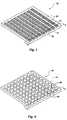
- FIG. 8is a perspective view of a portion of a wafer having a plurality of semiconductor devices thereon, depicting collars being fabricated around each of the contact pads of the semiconductor devices at the wafer level;
- FIG. 9is a schematic representation of an exemplary stereolithography apparatus that can be employed in the method of the present invention to fabricate the collars of the present invention.
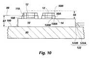
- FIG. 10is a partial cross-sectional side view of a semiconductor device disposed on a platform of a stereolithographic apparatus for the formation of collars around the contact pads of the semiconductor device.
- Semiconductor device 10can be a semiconductor die, a chip scale package, a ball grid array package, a carrier substrate, or any other type of semiconductor device component having contact pads to which conductive structures, such as balls, bumps, or pillars, can be attached.
- a collar 50surrounds the periphery of each contact pad 12 .
- Each collar 50has an aperture 52 , through which at least a portion of the surrounded contact pad 12 is exposed.
- Each collar 50protrudes from surface 14 of semiconductor device 10 so as to laterally surround at least a portion of a conductive structure to be bonded or otherwise secured to bond pad 12 and to prevent the material of a conductive structure from contacting portions of surface 14 adjacent to contact pad 12 .
- semiconductor device 10is shown in a face-down orientation over a higher level substrate 30 .
- Substrate 30has contact pads 32 , or terminals, exposed at a surface 34 thereof.
- Contact pads 32are preferably arranged so as to align with corresponding ones of contact pads 12 upon positioning semiconductor device 10 face-down over substrate 30 .
- Each contact pad 12 of semiconductor device 10is electrically connected to its corresponding contact pad 32 of substrate 30 by way of a conductive structure 20 , such as a bump, ball, or pillar, formed from a conductive material, such as a solder, other metal or metal alloy, a conductor filled epoxy, or a conductive epoxy.
- collars 50are at least partially fabricated prior to connecting conductive structures 20 to contact pads 12 .
- a base portion 22 of each conductive structure 20which is bonded or otherwise secured to the contact pad 12 exposed through aperture 52 of collar 50 , has a shape that is complementary to the configuration of aperture 52 .
- each collar 50contacts the conductive structure 20 that extends through aperture 52 .
- Base portion 22 of each conductive structure 20can have a shape that is defined by aperture 52 or that is configured complementarily to aperture 52 . Accordingly, collars 50 and the apertures 52 thereof can be configured to impart desired shapes and dimensions to conductive structures 20 or at least base portion 22 thereof.
- conductive structures 20can have base portions 22 that are not shaped complementarily to apertures 52 or that extend through apertures 52 without contacting collars 50 .
- semiconductor device 10is connected facedown to a higher level substrate 30 , such as a carrier substrate.
- Conductive structures 20connect contact pads 12 of semiconductor device 10 to corresponding contact pads 32 exposed at surface 34 of substrate 30 .
- collar 50prevents material of conductive structures 20 from contacting regions of surface 14 adjacent to contact pads 12 .
- collars 50contact conductive structures 20 so as to laterally support and protect at least the contacted portions of conductive structures 20 .
- FIGS. 4 and 5illustrate another semiconductor device 10 , which has conductive structures 20 ′, shown as solder bumps, protruding from each of the contact pads 12 on the surface 14 thereof.
- the portion of each conductive structure 20 ′ adjacent surface 14 and the periphery of each bond pad 12is laterally surrounded by another embodiment of collar 50 ′, which protrudes from surface 14 .
- conductive structure 20 ′extends through an aperture 52 ′ of collar 50 ′ to contact pad 12 .
- Collar 50 ′contacts the sides of the portion of conductive structure 20 ′ extending through aperture 52 ′.
- FIG. 5also depicts portions of collar 50 ′ located beneath conductive structure 20 ′. These portions of collar 50 ′ are referred to herein as “shadowed” areas 54 ′.
- semiconductor device 10depicted as being invertedly disposed over and connected to a higher level substrate 30 .
- Conductive structures 20 ′connect each contact pad 12 of semiconductor device 10 to a corresponding contact pad 32 exposed at a surface 34 of substrate 30 .
- collars 50 ′prevent material of conductive structures 20 ′ from contacting surface 14 of semiconductor device 10 .
- a collar 50 ′′can also protrude from surface 14 substantially the same distance as a pillar shaped conductive structure 20 ′′ secured to contact pad 12 .
- conductive structure 20 ′′can be formed by disposing a quantity of conductive material, such as a solder, metal, metal alloy, conductor filled epoxy, or conductive elastomer, into aperture 52 ′′.
- a pre-formed conductive structure 20 ′′can be secured to contact pad 12 and collar 50 ′′ fabricated around conductive structure 20 ′′.
- conductive structures 20are thinner than conductive structures 20 ′ (see FIGS. 4 - 6 ).
- conductive structures 20 , 20 ′′consume less area, or real estate, on semiconductor device 10 than conductive structures 20 ′. Accordingly, conductive structures 20 , 20 ′′ are spaced farther apart than conductive structures 20 ′.
- conductive structures 20 , 20 ′′can be used with semiconductor devices having tighter, or smaller, pitches than the pitches of semiconductor devices with which solder balls or similar conductive structures 20 ′ are used.
- conductive structures 20 , 20 ′′are thinner than solder balls, such as conductive structure 20 ′, conductive structures 20 , 20 ′′ also consume less conductive material than conductive structures 20 ′.
- FIG. 8illustrates collars 50 on semiconductor devices 10 , in this case semiconductor dice, that have yet to be singulated, or diced, from a wafer 72 or from a portion of a wafer 72 .
- semiconductor devices 10in this case semiconductor dice, that have yet to be singulated, or diced, from a wafer 72 or from a portion of a wafer 72 .
- Each semiconductor device 10 on wafer 72is separated from adjacent semiconductor devices 10 by a street 74 .
- collars 50 , 50 ′, 50 ′′are preferably substantially simultaneously fabricated on or secured to a collection of semiconductor devices 10 , such as prior to singulating semiconductor dice from a wafer 72
- collars 50 , 50 ′, 50 ′′can also be fabricated on or secured to collections of individual semiconductor devices 10 or other substrates, or to individual semiconductor devices 10 or other substrates, such as substrate 30 .
- collars 50 , 50 ′, 50 ′′can be substantially simultaneously fabricated on or secured to a collection of more than one type of semiconductor device 10 or other substrate.
- Collars 50 , 50 ′, 50 ′′can be fabricated directly on semiconductor devices 10 .
- collars 50 , 50 ′, 50 ′′can be fabricated separately from semiconductor devices 10 , then secured thereto as known in the art, such as by the use of a suitable adhesive.
- Collars 50 , 50 ′, 50 ′′are preferably fabricated from a photo-curable polymer, or “photopolymer” by stereolithographic processes. When fabricated directly on a semiconductor device 10 , collars 50 , 50 ′, 50 ′′ can be made either before or after conductive structures 20 , 20 ′, 20 ′′ are connected to contact pads 12 of semiconductor device 10 .
- FIG. 9schematically depicts various components, and operation, of an exemplary stereolithography apparatus 80 to facilitate the reader's understanding of the technology employed in implementation of the method of the present invention, although those of ordinary skill in the art will understand and appreciate that apparatus of other designs and manufacture may be employed in practicing the method of the present invention.
- the preferred, basic stereolithography apparatus for implementation of the method of the present invention, as well as operation of such apparatus,are described in great detail in United States Patents assigned to 3D Systems, Inc. of Valencia, Cali., such patents including, without limitation, U.S. Pat. Nos.
- a 3D CAD drawing of an object to be fabricated in the form of a data fileis placed in the memory of a computer 82 controlling the operation of apparatus 80 , if computer 82 is not a CAD computer in which the original object design is effected.
- an object designmay be effected in a first computer in an engineering or research facility and the data files transferred via wide or local area network, tape, disc, CD-ROM, or otherwise as known in the art to computer 82 of apparatus 80 for object fabrication.
- the datais preferably formatted in an STL (for STereoLithography) file, STL being a standardized format employed by a majority of manufacturers of stereolithography equipment. Fortunately, the format has been adopted for use in many solid-modeling CAD programs, so translation from another internal geometric database format is often unnecessary.
- STL filethe boundary surfaces of an object are defined as a mesh of interconnected triangles.
- Apparatus 80also includes a reservoir 84 (which may comprise a removable reservoir interchangeable with others containing different materials) of an unconsolidated material 86 to be employed in fabricating the intended object.
- the unconsolidated material 86is a liquid, photo-curable polymer, or “photopolymer”, that cures in response to light in the UV wavelength range.
- the surface level 88 of material 86is automatically maintained at an extremely precise, constant magnitude by devices known in the art responsive to output of sensors within apparatus 80 and preferably under control of computer 82 .
- a support platform or elevator 90precisely vertically movable in fine, repeatable increments responsive to control of computer 82 , is located for movement downward into and upward out of material 86 in reservoir 84 .
- An objectmay be fabricated directly on platform 90 , or on a substrate disposed on platform 90 .
- the substratemay be positioned on platform 90 and secured thereto by way of one or more base supports 122 .
- Such base supports 122may be fabricated before or simultaneously with the stereolithographic fabrication of one or more objects on platform 90 or a substrate disposed thereon.
- These supports 122may support, or prevent lateral movement of, the substrate relative to a surface 100 of platform 90 .
- Supports 122may also provide a perfectly horizontal reference plane for fabrication of one or more objects thereon, as well as facilitate the removal of a substrate from platform 90 following the stereolithographic fabrication of one or more objects on the substrate.
- supports 122can preclude inadvertent contact of recoater blade 102 , to be described in greater detail below, with surface 100 of platform 90 .
- Apparatus 80has a UV wavelength range laser plus associated optics and galvanometers (collectively identified as laser 92 ) for controlling the scan of laser beam 96 in the X-Y plane across platform 90 .
- Laser 92has associated therewith a mirror 94 to reflect beam 96 downwardly as beam 98 toward surface 100 of platform 90 .
- Beam 98is traversed in a selected pattern in the X-Y plane, that is to say in a plane parallel to surface 100 , by initiation of the galvanometers under control of computer 82 to at least partially cure, by impingement thereon, selected portions of material 86 disposed over surface 100 to at least a partially consolidated (e.g., semisolid) state.
- the use of mirror 94lengthens the path of the laser beam, effectively doubling same, and provides a more vertical beam 98 than would be possible if the laser 92 itself were mounted directly above platform surface 100 , thus enhancing resolution.
- data from the STL files resident in computer 82is manipulated to build an object, such as collar 50 , illustrated in FIGS. 1-3 and 8 , or base supports 122 , one layer at a time.
- the data mathematically representing one or more of the objects to be fabricatedare divided into subsets, each subset representing a slice or layer of the object.
- the division of datais effected by mathematically sectioning the 3D CAD model into at least one layer, a single layer or a “stack” of such layers representing the object.
- Each slicemay be from about 0.0001 to about 0.0300 inch thick. As mentioned previously, a thinner slice promotes higher resolution by enabling better reproduction of fine vertical surface features of the object or objects to be fabricated.
- supports 122may be programmed as a separate STL file from the other objects to be fabricated.
- the primary STL file for the object or objects to be fabricated and the STL file for base support(s) 122are merged.
- the operational parameters for apparatus 80are set to adjust the size (diameter if circular) of the laser light beam used to cure material 86 .
- computer 82automatically checks and, if necessary, adjusts by means known in the art the surface level 88 of material 86 in reservoir 84 to maintain same at an appropriate focal length for laser beam 98 .
- U.S. Pat. No. 5,174,931referenced above and previously incorporated herein by reference, discloses one suitable level control system.
- the height of mirror 94may be adjusted responsive to a detected surface level 88 to cause the focal point of laser beam 98 to be located precisely at the surface of material 86 at surface level 88 if level 88 is permitted to vary, although this approach is more complex.
- Platform 90may then be submerged in material 86 in reservoir 84 to a depth equal to the thickness of one layer or slice of the object to be formed, and the liquid surface level 88 is readjusted as required to accommodate material 86 displaced by submergence of platform 90 .
- Laser 92is then activated so laser beam 98 will scan unconsolidated (e.g., liquid or powdered) material 86 disposed over surface 100 of platform 90 to at least partially consolidate (e.g., polymerize to at least a semisolid state) material 86 at selected locations, defining the boundaries of a first layer 122 A of base support 122 and filling in solid portions thereof.
- Platform 90is then lowered by a distance equal to thickness of second layer 122 B, and laser beam 98 scanned over selected regions of the surface of material 86 to define and fill in the second layer while simultaneously bonding the second layer to the first. The process may be then repeated, as often as necessary, layer by layer, until base support 122 is completed.
- Platform 90is then moved relative to mirror 94 to form any additional base supports 122 on platform 90 or a substrate disposed thereon or to fabricate objects upon platform 90 , base support 122 , or a substrate, as provided in the control software.
- the number of layers required to erect support 122 or one or more other objects to be formeddepends upon the height of the object or objects to be formed and the desired layer thickness 108 , 110 .
- the layers of a stereolithographically fabricated structure with a plurality of layersmay have different thicknesses.
- a recoater blade 102is employed, the process sequence is somewhat different.
- surface 100 of platform 90is lowered into unconsolidated (e.g., liquid) material 86 below surface level 88 a distance greater than a thickness of a single layer of material 86 to be cured, then raised above surface level 88 until platform 90 , a substrate disposed thereon, or a structure being formed on platform 90 or a substrate thereon is precisely one layer's thickness below blade 102 .
- Blade 102then sweeps horizontally over platform 90 or (to save time) at least over a portion thereof on which one or more objects are to be fabricated to remove excess material 86 and leave a film of precisely the desired thickness.
- Platform 90is then lowered so that the surface of the film and material level 88 are coplanar and the surface of the unconsolidated material 86 is still.
- Laser 92is then initiated to scan with laser beam 98 and define the first layer 130 .
- the processis repeated, layer by layer, to define each succeeding layer 130 and simultaneously bond same to the next lower layer 130 until all of the layers of the object or objects to be fabricated are completed.
- a layer of unconsolidated (e.g., liquid) material 86may be formed on surface 100 of support platform 90 , on a substrate disposed on platform 90 , or on one or more objects being fabricated by lowering platform 90 to flood material 86 over surface 100 , over a substrate disposed thereon, or over the highest completed layer of the object or objects being formed, then raising platform 90 and horizontally traversing a so-called “meniscus” blade horizontally over platform 90 to form a layer of unconsolidated material having the desired thickness over platform 90 , the substrate, or each of the objects being formed.
- Laser 92is then initiated and a laser beam 98 scanned over the layer of unconsolidated material to define at least the boundaries of the solid regions the next higher layer of the object or objects being fabricated.
- Yet another alternative to layer preparation of unconsolidated (e.g., liquid) material 86is to merely lower platform 90 to a depth equal to that of a layer of material 86 to be scanned, and to then traverse a combination flood bar and meniscus bar assembly horizontally over platform 90 , a substrate disposed on platform 90 , or one or more objects being formed to substantially concurrently flood material 86 thereover and to define a precise layer thickness of material 86 for scanning.
- unconsolidated (e.g., liquid) material 86is to merely lower platform 90 to a depth equal to that of a layer of material 86 to be scanned, and to then traverse a combination flood bar and meniscus bar assembly horizontally over platform 90 , a substrate disposed on platform 90 , or one or more objects being formed to substantially concurrently flood material 86 thereover and to define a precise layer thickness of material 86 for scanning.
- a commercially available stereolithography apparatusoperating generally in the manner as that described above with respect to apparatus 80 of FIG. 9 is preferably employed, but with further additions and modifications as hereinafter described for practicing the method of the present invention.
- the SLA-250/SOHR, SLA-5000 and SLA-7000 stereolithography systemsare suitable for modification.
- Photopolymers believed to be suitable for use in practicing the present inventioninclude Cibatool SL 5170 and SL 5210 resins for the SLA-250/50HR system, Cibatool SL 5530 resin for the SLA-5000 and 7000 systems, and Cibatool-SL 7510 resin for the SLA-7000 system. All of these photopolymers are available from Ciba Specialty Chemicals Corporation.
- the layer thickness of material 86 to be formedmay be on the order of about 0.0001 to 0.0300 inch, with a high degree of uniformity. It should be noted that different material layers may have different heights, so as to form a structure of a precise, intended total height or to provide different material thicknesses for different portions of the structure.
- the size of the laser beam “spot” impinging on the surface of material 86 cure samemay be on the order of 0.001 inch to 0.008 inch.
- Resolutionis preferably ⁇ 0.0003 inch in the X-Y plane (parallel to surface 100 ) over at least a 0.5 inch ⁇ 0.25 inch field from a center point, permitting a high resolution scan effectively across a 1.0 inch ⁇ 0.5 inch area.
- the longer and more effectively vertical the path of laser beam 96 / 98the greater the achievable resolution.
- apparatus 80 useful in the method of the present inventionincludes a camera 140 which is in communication with computer 82 and preferably located, as shown, in close proximity to optics and scan controller 94 located above surface 100 of support platform 90 .
- Camera 140may be any one of a number of commercially available cameras, such as capacitive-coupled discharge (CCD) cameras available from a number of vendors.
- Suitable circuitry as required for adapting the output of camera 140 for use by computer 82may be incorporated in a board 142 installed in computer 82 , which is programmed as known in the art to respond to images generated by camera 140 and processed by board 142 .
- Camera 140 and board 142may together comprise a so-called “machine vision system” and, specifically, a “pattern recognition system” (PRS), operation of which will be described briefly below for a better understanding of the present invention.
- a self-contained machine vision systemavailable from a commercial vendor of such equipment may be employed.
- such systemsare available from Cognex Corporation of Natick, Mass.
- the apparatus of the Cognex BGA Inspection PackageTM or the SMD Placement Guidance PackageTMmay be adapted to the present invention, although it is believed that the MVS-8000TM product family and the Checkpoint® product line, the latter employed in combination with Cognex PatMaxTM software, may be especially suitable for use in the present invention.
- a data file representative of the size, configuration, thickness and surface topography of, for example, a particular type and design of semiconductor device 10 or other substrate upon which one or more collars 50 are to be mountedis placed in the memory of computer 82 . Also, if it is desired that the collars 50 be so positioned on semiconductor device 10 taking into consideration features of a higher level substrate 30 (see FIG. 3) to which semiconductor device 10 is to be connected, a data file representative of substrate 30 and the features thereof may be placed in memory.
- One or more semiconductor devices 10 , wafers 72 (see FIG. 8 ), or other substratesmay be placed on surface 100 of platform 90 for fabrication of collars 50 around contact pads 12 thereof. If one or more semiconductor devices 10 , wafers 72 , or other substrates are to be held on or supported above platform 90 by stereolithographically formed base supports 122 , one or more layers of material 86 are sequentially disposed on surface 100 and selectively altered by use of laser 92 to form base supports 122 .
- Camera 140is then activated to locate the position and orientation of each semiconductor device 10 , including those on a wafer 72 (see FIG. 8 ), or other substrate upon which collars 50 are to be fabricated.
- the features of each semiconductor device 10 , wafer 72 , or other substrateare compared with those in the data file residing in memory, the locational and orientational data for each semiconductor device 10 , wafer 72 , or other substrate then also being stored in memory.
- the data file representing the design size, shape and topography for each semiconductor device 10 or other substratemay be used at this juncture to detect physically defective or damaged semiconductor devices 10 or other substrates prior to fabricating collars 50 thereon or before conducting further processing or assembly of semiconductor device 10 or other substrates.
- each semiconductor device 10 or other substratecan be deleted from the process of fabricating collars 50 , from further processing, or from assembly with other components.
- data files for more than one type (size, thickness, configuration, surface topography) of each semiconductor device 10 or other substratemay be placed in computer memory and computer 82 programmed to recognize not only the locations and orientations of each semiconductor device 10 or other substrate, but also the type of semiconductor device 10 or other substrate at each location upon platform 90 so that material 86 may be at least partially consolidated by laser beam 98 in the correct pattern and to the height required to define collars 50 in the appropriate, desired locations on each semiconductor device 10 or other substrate.
- wafer 72 or the one or more semiconductor devices 10 or other substrates on platform 90may then be submerged partially below the surface level 88 of liquid material 86 to a depth greater than the thickness of a first layer of material 86 to be at least partially consolidated (e.g., cured to at least a semisolid state) to form the lowest layer 130 of each collar 50 at the appropriate location or locations on each semiconductor device 10 or other substrate, then raised to a depth equal to the layer thickness, surface 88 of material 86 being allowed to become calm.
- Photopolymers that are useful as material 86exhibit a desirable dielectric constant, are of sufficient (i.e., semiconductor grade) purity, exhibit good adherence to other semiconductor device materials, and have a similar coefficient of thermal expansion (CTE) to the material of conductive structures 20 (FIG. 3) (e.g., solder or other metal or metal alloy, or conductive or conductor filled epoxy).
- CTEcoefficient of thermal expansion
- the CTE of material 86is sufficiently similar to that of conductive structures 20 to prevent undue stressing thereof during thermal cycling of semiconductor device 10 or another substrate in testing, subsequent processing, and subsequent normal operation.
- Exemplary photopolymers exhibiting these propertiesare believed to include, but are not limited to, the above-referenced resins from Ciba Specialty Chemical Company.
- One particular concern in determining resin suitabilityis the substantial absence of mobile ions, specifically fluorides.
- Laser 92is then activated and scanned to direct beam 98 , under control of computer 82 , toward specific locations of surface 88 relative to each semiconductor device 10 or other substrate to effect the aforementioned partial cure of material 86 to form a first layer 50 A of each collar 50 .
- Platform 90is then lowered into reservoir 84 and raised a distance equal to the desired thickness of another layer 50 B of each collar 50 , and laser 92 is activated to add another layer 50 B to each collar 50 under construction. This sequence continues, layer by layer, until each of the layers of collars 50 have been completed.
- the first layer of collar 50is identified by numeral 50 A, and the second layer is identified by numeral 50 B.
- first layer of base support 122is identified by numeral 122 A and the second layer thereof is identified by numeral 122 B.
- both base support 122 and collar 50have only two layers. Collars 50 with any number of layers are, however, within the scope of the present invention. The use of a large number of layers may be employed to substantially simulate the shape of the outer surface of a conductive structure to be encompassed by collar 50 .
- Each layer 50 A, 50 B of collar 50is preferably built by first defining any internal and external object boundaries of that layer with laser beam 98 , then hatching solid areas of collar 50 located within the object boundaries with laser beam 98 .
- An internal boundary of a layermay comprise aperture 52 , a through-hole, a void, or a recess in collar 50 , for example. If a particular layer includes a boundary of a void in the object above or below that layer, then laser beam 98 is scanned in a series of closely-spaced, parallel vectors so as to develop a continuous surface, or skin, with improved strength and resolution. The time it takes to form each layer depends upon the geometry thereof, the surface tension and viscosity of material 86 , and the thickness of that layer.
- collars 50may each be formed as a partially cured outer skin extending above surface 14 of semiconductor device 10 or above surface 24 of test substrate 20 and forming a dam within which unconsolidated material 86 can be contained. This may be particularly useful where the collars 50 protrude a relatively high distance 56 from surface 14 .
- support platform 90may be submerged so that material 86 enters the area within the dam, raised above surface level 88 , and then laser beam 98 activated and scanned to at least partially cure material 86 residing within the dam or, alternatively, to merely cure a “skin” comprising the contact surface 52 , a final cure of the material of the collars 50 being effected subsequently by broad-source UV radiation in a chamber, or by thermal cure in an oven.
- collars 50 of extremely precise dimensionsmay be formed of material 86 by apparatus 80 in minimal time.
- the unconsolidated material 86 in shadowed areas 54 ′will become trapped therein as material 86 ′ adjacent to, and laterally outward from, shadowed areas 54 ′ is at least partially consolidated and as collar 50 ′, is built up around conductive structure 20 ′.
- Such trapped, unconsolidated material 86will eventually cure due to the cross-linking initiated in the outwardly adjacent photopolymer, and the cure can be subsequently accelerated as known in the art, such as by a thermal cure.
- platform 90is elevated above surface level 88 of material 86 and platform 90 is removed from apparatus 80 , along with any substrate (e.g., semiconductor device 10 , wafer 72 (see FIG. 8 ), or other substrate) disposed thereon and any stereolithographically fabricated structures, such as collars 50 .
- any substratee.g., semiconductor device 10 , wafer 72 (see FIG. 8 ), or other substrate
- unconsolidated material 86e.g., excess uncured liquid
- Each semiconductor device 10 , wafer 72 , or other substrateis removed from platform 90 , such as by cutting the substrate free of base supports 122 .
- base supports 122may be configured to readily release semiconductor devices 10 , wafers 72 , or other substrates.
- a solventmay be employed to release base supports 122 from platform 90 .
- release and solvent materialsare known in the art. See, for example, U.S. Pat. No. 5,447,822 referenced above and previously incorporated herein by reference.
- Collars 50 and semiconductor device 10 or test substrate 20may also be cleaned by use of known solvents that will not substantially degrade, deform, or damage collars 50 or a substrate to which collars 50 are secured.
- collars 50may then require postcuring. Collars 50 may have regions of unconsolidated material contained within a boundary or skin thereof or in a shadowed area 54 ′ (see FIGS. 5 and 6 ), or material 86 may be only partially consolidated (e.g., polymerized or cured) and exhibit only a portion (typically 40% to 60%) of its fully consolidated strength. Postcuring to completely harden collars 50 may be effected in another apparatus projecting UV radiation in a continuous manner over collars 50 or by thermal completion of the initial, UV-initiated partial cure.
- each collar 50 on each specific semiconductor device 10 or other substratemay vary, again responsive to output of camera 140 or one or more additional cameras 144 or 146 , shown in broken lines, detecting the protrusion of unusually high (or low) preplaced conductive structures which could affect the desired distance 56 that collars 50 will protrude from surface 14 .
- the lateral extent (e.g., diameter) of each preplaced conductive structuremay be recognized and the girth of the outer boundary of each collar 50 adjusted accordingly.
- laser 92is again activated to at least partially cure material 86 residing on each semiconductor device 10 or other substrate to form the layer or layers of each collar 50 .
- FIGS. 9 and 10illustrate the stereolithographic fabrication of collars 50 on a substrate, such as a semiconductor device 10 , a wafer 72 (FIG. 8 ), or another substrate, including a plurality of semiconductor devices 10 or other substrates
- collars 50can be fabricated separately from a substrate, then secured to a substrate, by known processes, such as by the use of a suitable adhesive material.
- Stereolithographyis also an advantageous method of fabricating collars 50 according to the present invention since stereolithography can be conducted at substantially ambient temperature, the small spot size and rapid traverse of laser beam 98 resulting in negligible thermal stress upon semiconductor devices 10 , wafers 72 , or other substrates, as well as on the features thereof.
- the stereolithography fabrication processmay also advantageously be conducted at the wafer level or on multiple substrates, saving fabrication time and expense.
- the stereolithography method of the present inventionrecognizes specific semiconductor devices 10 or other substrates 20 , variations between individual substrates are accommodated. Accordingly, when the stereolithography method of the present invention is employed, collars 50 can be simultaneously fabricated on different types of semiconductor devices 10 or other substrates, as well as on both semiconductor devices 10 and other substrates.
Landscapes
- Engineering & Computer Science (AREA)
- Microelectronics & Electronic Packaging (AREA)
- Computer Hardware Design (AREA)
- Power Engineering (AREA)
- Manufacturing & Machinery (AREA)
- Chemical & Material Sciences (AREA)
- Materials Engineering (AREA)
- Physics & Mathematics (AREA)
- Condensed Matter Physics & Semiconductors (AREA)
- General Physics & Mathematics (AREA)
- Wire Bonding (AREA)
- Exposure And Positioning Against Photoresist Photosensitive Materials (AREA)
Abstract
Description
Claims (70)
Priority Applications (7)
| Application Number | Priority Date | Filing Date | Title |
|---|---|---|---|
| US09/590,418US6569753B1 (en) | 2000-06-08 | 2000-06-08 | Collar positionable about a periphery of a contact pad and around a conductive structure secured to the contact pads, semiconductor device components including same, and methods for fabricating same |
| US10/107,969US6525408B2 (en) | 2000-06-08 | 2002-03-27 | Collar positionable about a periphery of a contact pad and around a conductive structure secured to the contact pads, semiconductor device components including same, and methods for fabricating same |
| US10/107,848US6911735B2 (en) | 2000-06-08 | 2002-03-27 | Collar positionable about a periphery of a contact pad and around a conductive structure secured to the contact pads, semiconductor device components including same, and methods for fabricating same |
| US10/328,558US20030098499A1 (en) | 2000-06-08 | 2002-12-23 | Collar positionable about a periphery of a contact pad and around a conductive structure secured to the contact pad, semiconductor device components including same, and methods for fabricating same |
| US10/446,384US7169693B2 (en) | 2000-06-08 | 2003-05-27 | Collar positionable about a periphery of a contact pad and around a conductive structure secured to the contact pads, semiconductor device components including same, and methods for fabricating same |
| US11/130,622US20050208704A1 (en) | 2000-06-08 | 2005-05-17 | Methods including fabrication of substrates and other semiconductor device components with collars on or around the contact pads thereof |
| US11/169,230US7095106B2 (en) | 2000-06-08 | 2005-06-28 | Collars, support structures, and forms for protruding conductive structures |
Applications Claiming Priority (1)
| Application Number | Priority Date | Filing Date | Title |
|---|---|---|---|
| US09/590,418US6569753B1 (en) | 2000-06-08 | 2000-06-08 | Collar positionable about a periphery of a contact pad and around a conductive structure secured to the contact pads, semiconductor device components including same, and methods for fabricating same |
Related Child Applications (4)
| Application Number | Title | Priority Date | Filing Date |
|---|---|---|---|
| US10/107,969DivisionUS6525408B2 (en) | 2000-06-08 | 2002-03-27 | Collar positionable about a periphery of a contact pad and around a conductive structure secured to the contact pads, semiconductor device components including same, and methods for fabricating same |
| US10/107,848ContinuationUS6911735B2 (en) | 2000-06-08 | 2002-03-27 | Collar positionable about a periphery of a contact pad and around a conductive structure secured to the contact pads, semiconductor device components including same, and methods for fabricating same |
| US10/107,848DivisionUS6911735B2 (en) | 2000-06-08 | 2002-03-27 | Collar positionable about a periphery of a contact pad and around a conductive structure secured to the contact pads, semiconductor device components including same, and methods for fabricating same |
| US10/446,384ContinuationUS7169693B2 (en) | 2000-06-08 | 2003-05-27 | Collar positionable about a periphery of a contact pad and around a conductive structure secured to the contact pads, semiconductor device components including same, and methods for fabricating same |
Publications (1)
| Publication Number | Publication Date |
|---|---|
| US6569753B1true US6569753B1 (en) | 2003-05-27 |
Family
ID=24362188
Family Applications (7)
| Application Number | Title | Priority Date | Filing Date |
|---|---|---|---|
| US09/590,418Expired - LifetimeUS6569753B1 (en) | 2000-06-08 | 2000-06-08 | Collar positionable about a periphery of a contact pad and around a conductive structure secured to the contact pads, semiconductor device components including same, and methods for fabricating same |
| US10/107,848Expired - Fee RelatedUS6911735B2 (en) | 2000-06-08 | 2002-03-27 | Collar positionable about a periphery of a contact pad and around a conductive structure secured to the contact pads, semiconductor device components including same, and methods for fabricating same |
| US10/107,969Expired - Fee RelatedUS6525408B2 (en) | 2000-06-08 | 2002-03-27 | Collar positionable about a periphery of a contact pad and around a conductive structure secured to the contact pads, semiconductor device components including same, and methods for fabricating same |
| US10/328,558AbandonedUS20030098499A1 (en) | 2000-06-08 | 2002-12-23 | Collar positionable about a periphery of a contact pad and around a conductive structure secured to the contact pad, semiconductor device components including same, and methods for fabricating same |
| US10/446,384Expired - LifetimeUS7169693B2 (en) | 2000-06-08 | 2003-05-27 | Collar positionable about a periphery of a contact pad and around a conductive structure secured to the contact pads, semiconductor device components including same, and methods for fabricating same |
| US11/130,622AbandonedUS20050208704A1 (en) | 2000-06-08 | 2005-05-17 | Methods including fabrication of substrates and other semiconductor device components with collars on or around the contact pads thereof |
| US11/169,230Expired - Fee RelatedUS7095106B2 (en) | 2000-06-08 | 2005-06-28 | Collars, support structures, and forms for protruding conductive structures |
Family Applications After (6)
| Application Number | Title | Priority Date | Filing Date |
|---|---|---|---|
| US10/107,848Expired - Fee RelatedUS6911735B2 (en) | 2000-06-08 | 2002-03-27 | Collar positionable about a periphery of a contact pad and around a conductive structure secured to the contact pads, semiconductor device components including same, and methods for fabricating same |
| US10/107,969Expired - Fee RelatedUS6525408B2 (en) | 2000-06-08 | 2002-03-27 | Collar positionable about a periphery of a contact pad and around a conductive structure secured to the contact pads, semiconductor device components including same, and methods for fabricating same |
| US10/328,558AbandonedUS20030098499A1 (en) | 2000-06-08 | 2002-12-23 | Collar positionable about a periphery of a contact pad and around a conductive structure secured to the contact pad, semiconductor device components including same, and methods for fabricating same |
| US10/446,384Expired - LifetimeUS7169693B2 (en) | 2000-06-08 | 2003-05-27 | Collar positionable about a periphery of a contact pad and around a conductive structure secured to the contact pads, semiconductor device components including same, and methods for fabricating same |
| US11/130,622AbandonedUS20050208704A1 (en) | 2000-06-08 | 2005-05-17 | Methods including fabrication of substrates and other semiconductor device components with collars on or around the contact pads thereof |
| US11/169,230Expired - Fee RelatedUS7095106B2 (en) | 2000-06-08 | 2005-06-28 | Collars, support structures, and forms for protruding conductive structures |
Country Status (1)
| Country | Link |
|---|---|
| US (7) | US6569753B1 (en) |
Cited By (19)
| Publication number | Priority date | Publication date | Assignee | Title |
|---|---|---|---|---|
| US20020043711A1 (en)* | 2000-06-08 | 2002-04-18 | Salman Akram | Stereolithographic method and apparatus for fabricating stabilizers for flip-chip type semiconductor devices and resulting structures |
| US20030043360A1 (en)* | 2001-08-30 | 2003-03-06 | Farnworth Warren M. | Methods and apparatus for stereolithographic processing of components and assemblies |
| US20030089999A1 (en)* | 2000-06-08 | 2003-05-15 | Salman Akram | Semiconductor devices having stereolithographically fabricated protective layers thereon through which contact pads are exposed and assemblies including the same |
| US20030170921A1 (en)* | 2000-06-08 | 2003-09-11 | Salman Akram | Methods for forming semiconductor devices so as to stabilize the same when positioned face-down over test substrates |
| US20030173665A1 (en)* | 2000-06-08 | 2003-09-18 | Grigg Ford B. | Support ring for use with a contact pad and semiconductor device compoents including the same |
| US20040014255A1 (en)* | 2002-07-22 | 2004-01-22 | Grigg Ford B. | Thick solder mask for confining encapsulant material over selected locations of a substrate, assemblies including the solder mask, and methods |
| US6773957B2 (en) | 2000-06-08 | 2004-08-10 | Micron Technology, Inc. | Stereolithographic method and apparatus for fabricating spacers for semiconductor devices and resulting structures |
| US20040266162A1 (en)* | 2003-06-30 | 2004-12-30 | Advanced Semiconductor Engineering, Inc. | Semiconductor wafer package and manufacturing method thereof |
| US6858927B2 (en)* | 2000-06-07 | 2005-02-22 | Micron Technology, Inc. | Semiconductor packages and methods for making the same |
| US20050277279A1 (en)* | 2004-06-14 | 2005-12-15 | Shijian Luo | Microfeature devices and methods for manufacturing microfeature devices |
| US20070001321A1 (en)* | 2004-06-14 | 2007-01-04 | Hembree David R | Semiconductor devices at least partially covered by a composite coating including particles dispersed through photopolymer material |
| DE102005055487B3 (en)* | 2005-11-18 | 2007-05-16 | Infineon Technologies Ag | Electronic structure with components connected via solderable connecting elements and method for its production |
| US20070148817A1 (en)* | 2000-06-08 | 2007-06-28 | Williams Vernon M | Methods for fabricating reinforced, self-aligning conductive structures for semiconductor device components |
| US20070292983A1 (en)* | 2004-11-29 | 2007-12-20 | N-Trig Ltd. | Methods for Manufacturing a Sensor Assembly |
| US7442643B2 (en) | 2004-09-02 | 2008-10-28 | Micron Technology, Inc. | Methods of forming conductive elements using organometallic layers and flowable, curable conductive materials |
| US7923298B2 (en) | 2007-09-07 | 2011-04-12 | Micron Technology, Inc. | Imager die package and methods of packaging an imager die on a temporary carrier |
| CN102194772A (en)* | 2010-03-16 | 2011-09-21 | 意法半导体(格勒诺布尔)公司 | Surface mount electronic component |
| DE102014101030A1 (en)* | 2014-01-03 | 2015-07-09 | Taiwan Semiconductor Manufacturing Company, Ltd. | Barrier structures between external electrical connection parts |
| US20160086902A1 (en)* | 2014-09-24 | 2016-03-24 | Taiwan Semiconductor Manufacturing Company Ltd. | Semiconductor package structure and manufacturing method thereof |
Families Citing this family (37)
| Publication number | Priority date | Publication date | Assignee | Title |
|---|---|---|---|---|
| US6583354B2 (en)* | 1999-04-27 | 2003-06-24 | International Business Machines Corporation | Method of reforming reformable members of an electronic package and the resultant electronic package |
| US6569753B1 (en)* | 2000-06-08 | 2003-05-27 | Micron Technology, Inc. | Collar positionable about a periphery of a contact pad and around a conductive structure secured to the contact pads, semiconductor device components including same, and methods for fabricating same |
| US6683375B2 (en)* | 2001-06-15 | 2004-01-27 | Fairchild Semiconductor Corporation | Semiconductor die including conductive columns |
| JP4318893B2 (en)* | 2002-06-03 | 2009-08-26 | 新光電気工業株式会社 | Semiconductor device and manufacturing method of semiconductor device |
| TWI393226B (en) | 2004-11-04 | 2013-04-11 | Taiwan Semiconductor Mfg | Nanotube-based filler |
| JP4123251B2 (en)* | 2005-07-07 | 2008-07-23 | セイコーエプソン株式会社 | Semiconductor device manufacturing substrate and semiconductor device manufacturing method |
| US7118940B1 (en)* | 2005-08-05 | 2006-10-10 | Delphi Technologies, Inc. | Method of fabricating an electronic package having underfill standoff |
| TWI284949B (en)* | 2005-09-09 | 2007-08-01 | Chipmos Technologies Inc | Bumped structure and its forming method |
| US7749806B2 (en)* | 2005-09-22 | 2010-07-06 | Chipmos Technologies Inc. | Fabricating process of a chip package structure |
| JP4738971B2 (en)* | 2005-10-14 | 2011-08-03 | Okiセミコンダクタ株式会社 | Semiconductor device and manufacturing method thereof |
| US7446398B2 (en)* | 2006-08-01 | 2008-11-04 | Taiwan Semiconductor Manufacturing Co., Ltd. | Bump pattern design for flip chip semiconductor package |
| GB0704753D0 (en) | 2007-03-13 | 2007-04-18 | Airbus Uk Ltd | Preparation of a component for use in a joint |
| US8456023B2 (en) | 2007-04-27 | 2013-06-04 | Freescale Semiconductor, Inc. | Semiconductor wafer processing |
| US8487428B2 (en)* | 2007-11-20 | 2013-07-16 | Fujitsu Limited | Method and system for providing a reliable semiconductor assembly |
| US7888758B2 (en)* | 2008-03-12 | 2011-02-15 | Aptina Imaging Corporation | Method of forming a permanent carrier and spacer wafer for wafer level optics and associated structure |
| US8159067B2 (en) | 2008-08-13 | 2012-04-17 | International Business Machines Corporation | Underfill flow guide structures |
| TWI464847B (en)* | 2009-12-07 | 2014-12-11 | Xintec Inc | Electronic device package and fabrication method thereof |
| US20110309481A1 (en)* | 2010-06-18 | 2011-12-22 | Rui Huang | Integrated circuit packaging system with flip chip mounting and method of manufacture thereof |
| CN102593068B (en)* | 2011-01-11 | 2015-08-19 | 颀邦科技股份有限公司 | Tapered bump structure |
| US8692390B2 (en)* | 2011-02-18 | 2014-04-08 | Chipbond Technology Corporation | Pyramid bump structure |
| CN102867758B (en)* | 2011-07-08 | 2015-12-02 | 颀邦科技股份有限公司 | Bump Manufacturing Process and Its Structure |
| US8563416B2 (en) | 2011-07-29 | 2013-10-22 | International Business Machines Corporation | Coaxial solder bump support structure |
| CN103107104A (en)* | 2011-11-11 | 2013-05-15 | 北京大学深圳研究生院 | Flip chip manufacture method |
| CN102437063A (en)* | 2011-11-25 | 2012-05-02 | 北京大学深圳研究生院 | A method of manufacturing a liquid bump flip chip |
| US8531040B1 (en)* | 2012-03-14 | 2013-09-10 | Honeywell International Inc. | Controlled area solder bonding for dies |
| CN104380543B (en)* | 2012-06-04 | 2016-03-02 | 松下知识产权经营株式会社 | Method for forming electrical connection structure part, method for manufacturing aluminum electric wire with terminal, electric connection structure part, motor equipped with same, electrical equipment with same, aluminum wire with terminal, motor with same, electric machine with same equipment |
| US9478498B2 (en) | 2013-08-05 | 2016-10-25 | Taiwan Semiconductor Manufacturing Company, Ltd. | Through package via (TPV) |
| JP6346283B2 (en)* | 2013-11-22 | 2018-06-20 | リキッドクール ソリューションズ, インク. | Scalable liquid immersion cooling device |
| GB2520952A (en) | 2013-12-04 | 2015-06-10 | Ibm | Flip-chip electronic device with carrier having heat dissipation elements free of solder mask |
| US10038267B2 (en)* | 2014-06-12 | 2018-07-31 | Palo Alto Research Center Incorporated | Circuit interconnect system and method |
| US9780052B2 (en) | 2015-09-14 | 2017-10-03 | Micron Technology, Inc. | Collars for under-bump metal structures and associated systems and methods |
| CN105336829B (en)* | 2015-09-28 | 2018-09-11 | 厦门市三安光电科技有限公司 | Inverted light-emitting diode (LED) structure and preparation method thereof |
| CN111010818B (en)* | 2019-11-15 | 2020-10-16 | 河北科技大学 | Smearing path planning method and device applied to tin paste smearing equipment |
| CN110996547B (en)* | 2019-11-15 | 2020-10-16 | 河北科技大学 | Driving parameter calculation method and device applied to tin paste smearing equipment |
| KR102743042B1 (en)* | 2020-02-24 | 2024-12-16 | 에스케이하이닉스 주식회사 | Semiconductor package including stacked semiconductor chips and method for fabricating the same |
| CN113172235B (en)* | 2021-04-02 | 2022-10-28 | 西安交通大学 | Electrical contact preparation method based on multi-material metal synchronous 3D printing technology |
| US11705421B2 (en)* | 2021-04-15 | 2023-07-18 | Micron Technology, Inc. | Apparatus including solder-core connectors and methods of manufacturing the same |
Citations (18)
| Publication number | Priority date | Publication date | Assignee | Title |
|---|---|---|---|---|
| US5173220A (en) | 1991-04-26 | 1992-12-22 | Motorola, Inc. | Method of manufacturing a three-dimensional plastic article |
| US5264061A (en) | 1992-10-22 | 1993-11-23 | Motorola, Inc. | Method of forming a three-dimensional printed circuit assembly |
| US5278442A (en) | 1991-07-15 | 1994-01-11 | Prinz Fritz B | Electronic packages and smart structures formed by thermal spray deposition |
| US5484314A (en) | 1994-10-13 | 1996-01-16 | Micron Semiconductor, Inc. | Micro-pillar fabrication utilizing a stereolithographic printing process |
| US5545367A (en) | 1992-04-15 | 1996-08-13 | Soane Technologies, Inc. | Rapid prototype three dimensional stereolithography |
| US5705117A (en) | 1996-03-01 | 1998-01-06 | Delco Electronics Corporaiton | Method of combining metal and ceramic inserts into stereolithography components |
| US5834366A (en)* | 1996-05-15 | 1998-11-10 | Micron Technology, Inc. | Method for fabricating microbump interconnect for bare semiconductor dice |
| US5915170A (en) | 1994-09-20 | 1999-06-22 | Tessera, Inc. | Multiple part compliant interface for packaging of a semiconductor chip and method therefor |
| US5924003A (en)* | 1997-11-14 | 1999-07-13 | Kinetrix, Inc. | Method of manufacturing ball grid arrays for improved testability |
| US5934545A (en) | 1997-02-21 | 1999-08-10 | Gordon; Thomas A. | Ball placement method and apparatus for forming a ball grid array |
| US6013571A (en)* | 1997-06-16 | 2000-01-11 | Motorola, Inc. | Microelectronic assembly including columnar interconnections and method for forming same |
| US6110760A (en)* | 1998-02-12 | 2000-08-29 | Micron Technology, Inc. | Methods of forming electrically conductive interconnections and electrically interconnected substrates |
| US6180504B1 (en) | 1999-08-27 | 2001-01-30 | Micron Technology, Inc. | Method for fabricating a semiconductor component with external polymer support layer |
| US6274473B1 (en)* | 1997-05-08 | 2001-08-14 | Advanced Micro Devices, Inc. | Flip chip packages |
| US6274474B1 (en)* | 1999-10-25 | 2001-08-14 | International Business Machines Corporation | Method of forming BGA interconnections having mixed solder profiles |
| US6297141B1 (en)* | 1997-03-03 | 2001-10-02 | Nec Corporation | Mounting assembly of integrated circuit device and method for production thereof |
| US6333104B1 (en)* | 2000-05-30 | 2001-12-25 | International Business Machines Corporation | Conductive polymer interconnection configurations |
| US6352881B1 (en)* | 1999-07-22 | 2002-03-05 | National Semiconductor Corporation | Method and apparatus for forming an underfill adhesive layer |
Family Cites Families (27)
| Publication number | Priority date | Publication date | Assignee | Title |
|---|---|---|---|---|
| US5281684A (en)* | 1992-04-30 | 1994-01-25 | Motorola, Inc. | Solder bumping of integrated circuit die |
| JPH0817860A (en)* | 1994-06-30 | 1996-01-19 | Oki Electric Ind Co Ltd | Manufacture of electronic part |
| US5608260A (en)* | 1994-12-30 | 1997-03-04 | International Business Machines Corporation | Leadframe having contact pads defined by a polymer insulating film |
| WO1999004430A1 (en)* | 1997-07-21 | 1999-01-28 | Aguila Technologies, Inc. | Semiconductor flip-chip package and method for the fabrication thereof |
| US5993554A (en)* | 1998-01-22 | 1999-11-30 | Optemec Design Company | Multiple beams and nozzles to increase deposition rate |
| US5977632A (en)* | 1998-02-02 | 1999-11-02 | Motorola, Inc. | Flip chip bump structure and method of making |
| US6089151A (en)* | 1998-02-24 | 2000-07-18 | Micron Technology, Inc. | Method and stencil for extruding material on a substrate |
| US6251488B1 (en)* | 1999-05-05 | 2001-06-26 | Optomec Design Company | Precision spray processes for direct write electronic components |
| JP3960445B2 (en)* | 1998-10-12 | 2007-08-15 | 新光電気工業株式会社 | Semiconductor device and manufacturing method thereof |
| DE19907168C1 (en)* | 1999-02-19 | 2000-08-10 | Micronas Intermetall Gmbh | Layer arrangement and method for its production |
| US6524346B1 (en)* | 1999-02-26 | 2003-02-25 | Micron Technology, Inc. | Stereolithographic method for applying materials to electronic component substrates and resulting structures |
| US6259962B1 (en)* | 1999-03-01 | 2001-07-10 | Objet Geometries Ltd. | Apparatus and method for three dimensional model printing |
| US6583354B2 (en)* | 1999-04-27 | 2003-06-24 | International Business Machines Corporation | Method of reforming reformable members of an electronic package and the resultant electronic package |
| US6391251B1 (en)* | 1999-07-07 | 2002-05-21 | Optomec Design Company | Forming structures from CAD solid models |
| JP2001044358A (en)* | 1999-07-28 | 2001-02-16 | Mitsubishi Electric Corp | Semiconductor device and method of manufacturing the same |
| US6297562B1 (en)* | 1999-09-20 | 2001-10-02 | Telefonaktieboalget Lm Ericsson (Publ) | Semiconductive chip having a bond pad located on an active device |
| US6326698B1 (en) | 2000-06-08 | 2001-12-04 | Micron Technology, Inc. | Semiconductor devices having protective layers thereon through which contact pads are exposed and stereolithographic methods of fabricating such semiconductor devices |
| US6506671B1 (en) | 2000-06-08 | 2003-01-14 | Micron Technology, Inc. | Ring positionable about a periphery of a contact pad, semiconductor device components including same, and methods for positioning the ring around a contact pad |
| US6461881B1 (en)* | 2000-06-08 | 2002-10-08 | Micron Technology, Inc. | Stereolithographic method and apparatus for fabricating spacers for semiconductor devices and resulting structures |
| US7041533B1 (en) | 2000-06-08 | 2006-05-09 | Micron Technology, Inc. | Stereolithographic method for fabricating stabilizers for semiconductor devices |
| US6569753B1 (en)* | 2000-06-08 | 2003-05-27 | Micron Technology, Inc. | Collar positionable about a periphery of a contact pad and around a conductive structure secured to the contact pads, semiconductor device components including same, and methods for fabricating same |
| US7138653B1 (en) | 2000-06-08 | 2006-11-21 | Micron Technology, Inc. | Structures for stabilizing semiconductor devices relative to test substrates and methods for fabricating the stabilizers |
| US20020171177A1 (en) | 2001-03-21 | 2002-11-21 | Kritchman Elisha M. | System and method for printing and supporting three dimensional objects |
| US6501139B1 (en) | 2001-03-30 | 2002-12-31 | Matrix Semiconductor, Inc. | High-voltage transistor and fabrication process |
| US7275925B2 (en) | 2001-08-30 | 2007-10-02 | Micron Technology, Inc. | Apparatus for stereolithographic processing of components and assemblies |
| US20030151167A1 (en) | 2002-01-03 | 2003-08-14 | Kritchman Eliahu M. | Device, system and method for accurate printing of three dimensional objects |
| US6984545B2 (en)* | 2002-07-22 | 2006-01-10 | Micron Technology, Inc. | Methods of encapsulating selected locations of a semiconductor die assembly using a thick solder mask |
- 2000
- 2000-06-08USUS09/590,418patent/US6569753B1/ennot_activeExpired - Lifetime
- 2002
- 2002-03-27USUS10/107,848patent/US6911735B2/ennot_activeExpired - Fee Related
- 2002-03-27USUS10/107,969patent/US6525408B2/ennot_activeExpired - Fee Related
- 2002-12-23USUS10/328,558patent/US20030098499A1/ennot_activeAbandoned
- 2003
- 2003-05-27USUS10/446,384patent/US7169693B2/ennot_activeExpired - Lifetime
- 2005
- 2005-05-17USUS11/130,622patent/US20050208704A1/ennot_activeAbandoned
- 2005-06-28USUS11/169,230patent/US7095106B2/ennot_activeExpired - Fee Related
Patent Citations (19)
| Publication number | Priority date | Publication date | Assignee | Title |
|---|---|---|---|---|
| US5173220A (en) | 1991-04-26 | 1992-12-22 | Motorola, Inc. | Method of manufacturing a three-dimensional plastic article |
| US5278442A (en) | 1991-07-15 | 1994-01-11 | Prinz Fritz B | Electronic packages and smart structures formed by thermal spray deposition |
| US5545367A (en) | 1992-04-15 | 1996-08-13 | Soane Technologies, Inc. | Rapid prototype three dimensional stereolithography |
| US5264061A (en) | 1992-10-22 | 1993-11-23 | Motorola, Inc. | Method of forming a three-dimensional printed circuit assembly |
| US5915170A (en) | 1994-09-20 | 1999-06-22 | Tessera, Inc. | Multiple part compliant interface for packaging of a semiconductor chip and method therefor |
| US5484314A (en) | 1994-10-13 | 1996-01-16 | Micron Semiconductor, Inc. | Micro-pillar fabrication utilizing a stereolithographic printing process |
| US5705117A (en) | 1996-03-01 | 1998-01-06 | Delco Electronics Corporaiton | Method of combining metal and ceramic inserts into stereolithography components |
| US5834366A (en)* | 1996-05-15 | 1998-11-10 | Micron Technology, Inc. | Method for fabricating microbump interconnect for bare semiconductor dice |
| US5934545A (en) | 1997-02-21 | 1999-08-10 | Gordon; Thomas A. | Ball placement method and apparatus for forming a ball grid array |
| US6297141B1 (en)* | 1997-03-03 | 2001-10-02 | Nec Corporation | Mounting assembly of integrated circuit device and method for production thereof |
| US6274473B1 (en)* | 1997-05-08 | 2001-08-14 | Advanced Micro Devices, Inc. | Flip chip packages |
| US6013571A (en)* | 1997-06-16 | 2000-01-11 | Motorola, Inc. | Microelectronic assembly including columnar interconnections and method for forming same |
| US5924003A (en)* | 1997-11-14 | 1999-07-13 | Kinetrix, Inc. | Method of manufacturing ball grid arrays for improved testability |
| US6143639A (en)* | 1998-02-12 | 2000-11-07 | Micron Technology, Inc. | Methods of forming electrically conductive interconnections and electrically interconnected substrates |
| US6110760A (en)* | 1998-02-12 | 2000-08-29 | Micron Technology, Inc. | Methods of forming electrically conductive interconnections and electrically interconnected substrates |
| US6352881B1 (en)* | 1999-07-22 | 2002-03-05 | National Semiconductor Corporation | Method and apparatus for forming an underfill adhesive layer |
| US6180504B1 (en) | 1999-08-27 | 2001-01-30 | Micron Technology, Inc. | Method for fabricating a semiconductor component with external polymer support layer |
| US6274474B1 (en)* | 1999-10-25 | 2001-08-14 | International Business Machines Corporation | Method of forming BGA interconnections having mixed solder profiles |
| US6333104B1 (en)* | 2000-05-30 | 2001-12-25 | International Business Machines Corporation | Conductive polymer interconnection configurations |
Cited By (74)
| Publication number | Priority date | Publication date | Assignee | Title |
|---|---|---|---|---|
| US6858927B2 (en)* | 2000-06-07 | 2005-02-22 | Micron Technology, Inc. | Semiconductor packages and methods for making the same |
| US6893904B2 (en) | 2000-06-08 | 2005-05-17 | Micron Technology, Inc. | Stereolithographic methods of fabricating semiconductor devices having protective layers thereon through which contact pads are exposed |
| US6861763B2 (en) | 2000-06-08 | 2005-03-01 | Micron Technology, Inc. | Semiconductor devices having stereolithographically fabricated protective layers thereon through which contact pads are exposed and assemblies including the same |
| US20030092220A1 (en)* | 2000-06-08 | 2003-05-15 | Salman Akram | Stereolithographic methods of fabricating semiconductor devices having protective layers thereon through which contact pads are exposed |
| US20030170921A1 (en)* | 2000-06-08 | 2003-09-11 | Salman Akram | Methods for forming semiconductor devices so as to stabilize the same when positioned face-down over test substrates |
| US20030173665A1 (en)* | 2000-06-08 | 2003-09-18 | Grigg Ford B. | Support ring for use with a contact pad and semiconductor device compoents including the same |
| US20030176016A1 (en)* | 2000-06-08 | 2003-09-18 | Grigg Ford B. | Methods for providing support for conductive structures protruding from semiconductor device components |
| US20020043711A1 (en)* | 2000-06-08 | 2002-04-18 | Salman Akram | Stereolithographic method and apparatus for fabricating stabilizers for flip-chip type semiconductor devices and resulting structures |
| US7557452B1 (en) | 2000-06-08 | 2009-07-07 | Micron Technology, Inc. | Reinforced, self-aligning conductive structures for semiconductor device components and methods for fabricating same |
| US7138653B1 (en) | 2000-06-08 | 2006-11-21 | Micron Technology, Inc. | Structures for stabilizing semiconductor devices relative to test substrates and methods for fabricating the stabilizers |
| US20050156331A1 (en)* | 2000-06-08 | 2005-07-21 | Salman Akram | Semiconductor devices having stereolithographically fabricated protective layers thereon through which contact pads are exposed and assemblies including the same |
| US6773957B2 (en) | 2000-06-08 | 2004-08-10 | Micron Technology, Inc. | Stereolithographic method and apparatus for fabricating spacers for semiconductor devices and resulting structures |
| US20070148817A1 (en)* | 2000-06-08 | 2007-06-28 | Williams Vernon M | Methods for fabricating reinforced, self-aligning conductive structures for semiconductor device components |
| US7166925B2 (en) | 2000-06-08 | 2007-01-23 | Micron Technology, Inc. | Semiconductor devices having stereolithographically fabricated protective layers thereon through which contact pads are exposed and assemblies including the same |
| US7041513B2 (en) | 2000-06-08 | 2006-05-09 | Micron Technology, Inc. | Methods for forming semiconductor devices so as to stabilize the same when positioned face-down over test substrates |
| US6882049B2 (en) | 2000-06-08 | 2005-04-19 | Micron Technology, Inc. | Support ring for use with a contact pad and semiconductor device components including the same |
| US7109106B2 (en) | 2000-06-08 | 2006-09-19 | Micron Technology, Inc. | Methods for providing support for conductive structures protruding from semiconductor device components |
| US20030089999A1 (en)* | 2000-06-08 | 2003-05-15 | Salman Akram | Semiconductor devices having stereolithographically fabricated protective layers thereon through which contact pads are exposed and assemblies including the same |
| US20060189005A1 (en)* | 2000-06-08 | 2006-08-24 | Salman Akram | Methods for fabricating semiconductor devices so as to stabilize the same when contact-bearing surfaces thereof face over test substrates |
| US6902995B2 (en) | 2000-06-08 | 2005-06-07 | Micron Technology, Inc. | Ring positionable about a periphery of a contact pad, semiconductor device components including same, and methods for positioning the ring around a contact pad |
| US20050156314A1 (en)* | 2000-06-08 | 2005-07-21 | Grigg Ford B. | Support ring for use with a contact pad and semiconductor device components including the same |
| US7041533B1 (en) | 2000-06-08 | 2006-05-09 | Micron Technology, Inc. | Stereolithographic method for fabricating stabilizers for semiconductor devices |
| US6946732B2 (en) | 2000-06-08 | 2005-09-20 | Micron Technology, Inc. | Stabilizers for flip-chip type semiconductor devices and semiconductor device components and assemblies including the same |
| US20050227411A1 (en)* | 2000-06-08 | 2005-10-13 | Grigg Ford B | Methods for fabricating electronic components to include supports for conductive structures |
| US20050269714A1 (en)* | 2000-06-08 | 2005-12-08 | Salman Akram | Semiconductor device components with structures for stabilizing the semiconductor device components upon flip-chip arrangement with high-level substrates |
| US20070117277A1 (en)* | 2000-06-08 | 2007-05-24 | Salman Akram | Methods for fabricating protective layers on semiconductor device components |
| US20050282313A1 (en)* | 2000-06-08 | 2005-12-22 | Salman Akram | Methods for modifying semiconductor devices to stabilize the same and semiconductor device assembly |
| US7170171B2 (en) | 2000-06-08 | 2007-01-30 | Micron Technology, Inc. | Support ring for use with a contact pad and semiconductor device components including the same |
| US20040142058A1 (en)* | 2001-08-30 | 2004-07-22 | Farnworth Warren M. | Apparatus and methods for use in stereolithographic processing of components and assemblies |
| US20070134359A1 (en)* | 2001-08-30 | 2007-06-14 | Farnworth Warren M | Apparatus for use in stereolithographic processing of components and assemblies |
| US6911173B2 (en) | 2001-08-30 | 2005-06-28 | Micron Technology, Inc. | Methods for stereolithographic processing of components and assemblies |
| US20030043360A1 (en)* | 2001-08-30 | 2003-03-06 | Farnworth Warren M. | Methods and apparatus for stereolithographic processing of components and assemblies |
| US7275925B2 (en) | 2001-08-30 | 2007-10-02 | Micron Technology, Inc. | Apparatus for stereolithographic processing of components and assemblies |
| US20030207213A1 (en)* | 2001-08-30 | 2003-11-06 | Farnworth Warren M. | Methods for stereolithographic processing of components and assemblies |
| US7138724B2 (en) | 2002-07-22 | 2006-11-21 | Micron Technology, Inc. | Thick solder mask for confining encapsulant material over selected locations of a substrate and assemblies including the solder mask |
| US7125748B2 (en) | 2002-07-22 | 2006-10-24 | Micron Technology, Inc. | Methods of encapsulating selected locations of a semiconductor die assembly using a thick solder mask |
| US20060205117A1 (en)* | 2002-07-22 | 2006-09-14 | Grigg Ford B | Solder masks used in encapsulation, assemblies including the solar mask, and methods |
| US20040080027A1 (en)* | 2002-07-22 | 2004-04-29 | Grigg Ford B. | Thick solder mask for confining encapsulant material over selected location of a substrate and assemblies including the solder mask |
| US20040014255A1 (en)* | 2002-07-22 | 2004-01-22 | Grigg Ford B. | Thick solder mask for confining encapsulant material over selected locations of a substrate, assemblies including the solder mask, and methods |
| US6984545B2 (en) | 2002-07-22 | 2006-01-10 | Micron Technology, Inc. | Methods of encapsulating selected locations of a semiconductor die assembly using a thick solder mask |
| US20050181545A1 (en)* | 2002-07-22 | 2005-08-18 | Grigg Ford B. | Methods of encapsulating selected locations of a semiconductor die assembly using a thick solder mask |
| US7122459B2 (en)* | 2003-06-30 | 2006-10-17 | Advanced Semiconductor Engineering, Inc. | Semiconductor wafer package and manufacturing method thereof |
| US20060286791A1 (en)* | 2003-06-30 | 2006-12-21 | Advanced Semiconductor Engineering, Inc. | Semiconductor wafer package and manufacturing method thereof |
| US20040266162A1 (en)* | 2003-06-30 | 2004-12-30 | Advanced Semiconductor Engineering, Inc. | Semiconductor wafer package and manufacturing method thereof |
| US20070001321A1 (en)* | 2004-06-14 | 2007-01-04 | Hembree David R | Semiconductor devices at least partially covered by a composite coating including particles dispersed through photopolymer material |
| US7282806B2 (en) | 2004-06-14 | 2007-10-16 | Micron Technology, Inc. | Semiconductor devices at least partially covered by a composite coating including particles dispersed through photopolymer material |
| US7547978B2 (en) | 2004-06-14 | 2009-06-16 | Micron Technology, Inc. | Underfill and encapsulation of semiconductor assemblies with materials having differing properties |
| US7199037B2 (en)* | 2004-06-14 | 2007-04-03 | Micron Technology, Inc. | Microfeature devices and methods for manufacturing microfeature devices |
| US20060189118A1 (en)* | 2004-06-14 | 2006-08-24 | Micron Technology, Inc. | Microfeature devices and methods for manufacturing microfeature devices |
| US7253089B2 (en) | 2004-06-14 | 2007-08-07 | Micron Technology, Inc. | Microfeature devices and methods for manufacturing microfeature devices |
| US20060194424A1 (en)* | 2004-06-14 | 2006-08-31 | Micron Technology, Inc. | Microfeature devices and methods for manufacturing microfeature devices |
| US20050277279A1 (en)* | 2004-06-14 | 2005-12-15 | Shijian Luo | Microfeature devices and methods for manufacturing microfeature devices |
| US7411297B2 (en) | 2004-06-14 | 2008-08-12 | Micron Technology, Inc. | Microfeature devices and methods for manufacturing microfeature devices |
| US7442643B2 (en) | 2004-09-02 | 2008-10-28 | Micron Technology, Inc. | Methods of forming conductive elements using organometallic layers and flowable, curable conductive materials |
| US7488618B2 (en) | 2004-09-02 | 2009-02-10 | Micron Technology, Inc. | Microlenses including a plurality of mutually adhered layers of optically transmissive material and systems including the same |
| US7521296B2 (en) | 2004-09-02 | 2009-04-21 | Micron Technology, Inc. | Methods of fabricating a microlens including selectively curing flowable, uncured optically trasmissive material |
| US20070292983A1 (en)* | 2004-11-29 | 2007-12-20 | N-Trig Ltd. | Methods for Manufacturing a Sensor Assembly |
| US7906364B2 (en)* | 2004-11-29 | 2011-03-15 | N-Trig Ltd. | Methods for manufacturing a sensor assembly |
| DE102005055487B3 (en)* | 2005-11-18 | 2007-05-16 | Infineon Technologies Ag | Electronic structure with components connected via solderable connecting elements and method for its production |
| US7666777B2 (en) | 2005-11-18 | 2010-02-23 | Infineon Technologies Ag | Electronic structure with components connected by way of solderable connecting elements and method |
| US20070117424A1 (en)* | 2005-11-18 | 2007-05-24 | Michael Bauer | Electronic structure with components connected by way of solderable connecting elements and method |
| US7923298B2 (en) | 2007-09-07 | 2011-04-12 | Micron Technology, Inc. | Imager die package and methods of packaging an imager die on a temporary carrier |
| CN102194772A (en)* | 2010-03-16 | 2011-09-21 | 意法半导体(格勒诺布尔)公司 | Surface mount electronic component |
| US20110227222A1 (en)* | 2010-03-16 | 2011-09-22 | Romain Coffy | Surface-mounted electronic component |
| US8754523B2 (en)* | 2010-03-16 | 2014-06-17 | Stmicroelectronics (Grenoble 2) Sas | Surface-mounted electronic component |
| DE102014101030A1 (en)* | 2014-01-03 | 2015-07-09 | Taiwan Semiconductor Manufacturing Company, Ltd. | Barrier structures between external electrical connection parts |
| US9698079B2 (en) | 2014-01-03 | 2017-07-04 | Taiwan Semiconductor Manufacturing Company, Ltd. | Barrier structures between external electrical connectors |
| US10347563B2 (en) | 2014-01-03 | 2019-07-09 | Taiwan Semiconductor Manufacturing Company, Ltd. | Barrier structures between external electrical connectors |
| DE102014101030B4 (en)* | 2014-01-03 | 2021-06-24 | Taiwan Semiconductor Manufacturing Company, Ltd. | Barrier structures between external electrical connection parts and the corresponding process |
| US11296012B2 (en)* | 2014-01-03 | 2022-04-05 | Taiwan Semiconductor Manufacturing Company, Ltd. | Barrier structures between external electrical connectors |
| US20220230940A1 (en)* | 2014-01-03 | 2022-07-21 | Taiwan Semiconductor Manufacturing Co., Ltd. | Barrier Structures Between External Electrical Connectors |
| US12218035B2 (en)* | 2014-01-03 | 2025-02-04 | Taiwan Semiconductor Manufacturing Company, Ltd. | Barrier structures between external electrical connectors |
| US20160086902A1 (en)* | 2014-09-24 | 2016-03-24 | Taiwan Semiconductor Manufacturing Company Ltd. | Semiconductor package structure and manufacturing method thereof |
| US9711474B2 (en)* | 2014-09-24 | 2017-07-18 | Taiwan Semiconductor Manufacturing Company Ltd. | Semiconductor package structure with polymeric layer and manufacturing method thereof |
Also Published As
| Publication number | Publication date |
|---|---|
| US7095106B2 (en) | 2006-08-22 |
| US20020100973A1 (en) | 2002-08-01 |
| US20020105074A1 (en) | 2002-08-08 |
| US20030098499A1 (en) | 2003-05-29 |
| US20030203612A1 (en) | 2003-10-30 |
| US6911735B2 (en) | 2005-06-28 |
| US20060017175A1 (en) | 2006-01-26 |
| US6525408B2 (en) | 2003-02-25 |
| US7169693B2 (en) | 2007-01-30 |
| US20050208704A1 (en) | 2005-09-22 |
Similar Documents
| Publication | Publication Date | Title |
|---|---|---|
| US6569753B1 (en) | Collar positionable about a periphery of a contact pad and around a conductive structure secured to the contact pads, semiconductor device components including same, and methods for fabricating same | |
| US6902995B2 (en) | Ring positionable about a periphery of a contact pad, semiconductor device components including same, and methods for positioning the ring around a contact pad | |
| US7557452B1 (en) | Reinforced, self-aligning conductive structures for semiconductor device components and methods for fabricating same | |
| US6740962B1 (en) | Tape stiffener, semiconductor device component assemblies including same, and stereolithographic methods for fabricating same | |
| US6630365B2 (en) | Stereolithographic method and apparatus for fabricating spacers for semiconductor devices and resulting structures | |
| US7041533B1 (en) | Stereolithographic method for fabricating stabilizers for semiconductor devices | |
| US7041532B2 (en) | Methods for fabricating interposers including upwardly protruding dams |
Legal Events
| Date | Code | Title | Description |
|---|---|---|---|
| AS | Assignment | Owner name:MICRON TECHNOLOGY, INC., IDAHO Free format text:ASSIGNMENT OF ASSIGNORS INTEREST;ASSIGNORS:AKRAM, SALMAN;AHMAD, SYED SAJID;REEL/FRAME:010865/0088 Effective date:20000309 | |
| STCF | Information on status: patent grant | Free format text:PATENTED CASE | |
| CC | Certificate of correction | ||
| FPAY | Fee payment | Year of fee payment:4 | |
| FEPP | Fee payment procedure | Free format text:PAYOR NUMBER ASSIGNED (ORIGINAL EVENT CODE: ASPN); ENTITY STATUS OF PATENT OWNER: LARGE ENTITY | |
| FPAY | Fee payment | Year of fee payment:8 | |
| FPAY | Fee payment | Year of fee payment:12 | |
| AS | Assignment | Owner name:U.S. BANK NATIONAL ASSOCIATION, AS COLLATERAL AGENT, CALIFORNIA Free format text:SECURITY INTEREST;ASSIGNOR:MICRON TECHNOLOGY, INC.;REEL/FRAME:038669/0001 Effective date:20160426 Owner name:U.S. BANK NATIONAL ASSOCIATION, AS COLLATERAL AGEN Free format text:SECURITY INTEREST;ASSIGNOR:MICRON TECHNOLOGY, INC.;REEL/FRAME:038669/0001 Effective date:20160426 | |
| AS | Assignment | Owner name:MORGAN STANLEY SENIOR FUNDING, INC., AS COLLATERAL AGENT, MARYLAND Free format text:PATENT SECURITY AGREEMENT;ASSIGNOR:MICRON TECHNOLOGY, INC.;REEL/FRAME:038954/0001 Effective date:20160426 Owner name:MORGAN STANLEY SENIOR FUNDING, INC., AS COLLATERAL Free format text:PATENT SECURITY AGREEMENT;ASSIGNOR:MICRON TECHNOLOGY, INC.;REEL/FRAME:038954/0001 Effective date:20160426 | |
| AS | Assignment | Owner name:U.S. BANK NATIONAL ASSOCIATION, AS COLLATERAL AGENT, CALIFORNIA Free format text:CORRECTIVE ASSIGNMENT TO CORRECT THE REPLACE ERRONEOUSLY FILED PATENT #7358718 WITH THE CORRECT PATENT #7358178 PREVIOUSLY RECORDED ON REEL 038669 FRAME 0001. ASSIGNOR(S) HEREBY CONFIRMS THE SECURITY INTEREST;ASSIGNOR:MICRON TECHNOLOGY, INC.;REEL/FRAME:043079/0001 Effective date:20160426 Owner name:U.S. BANK NATIONAL ASSOCIATION, AS COLLATERAL AGEN Free format text:CORRECTIVE ASSIGNMENT TO CORRECT THE REPLACE ERRONEOUSLY FILED PATENT #7358718 WITH THE CORRECT PATENT #7358178 PREVIOUSLY RECORDED ON REEL 038669 FRAME 0001. ASSIGNOR(S) HEREBY CONFIRMS THE SECURITY INTEREST;ASSIGNOR:MICRON TECHNOLOGY, INC.;REEL/FRAME:043079/0001 Effective date:20160426 | |
| AS | Assignment | Owner name:JPMORGAN CHASE BANK, N.A., AS COLLATERAL AGENT, ILLINOIS Free format text:SECURITY INTEREST;ASSIGNORS:MICRON TECHNOLOGY, INC.;MICRON SEMICONDUCTOR PRODUCTS, INC.;REEL/FRAME:047540/0001 Effective date:20180703 Owner name:JPMORGAN CHASE BANK, N.A., AS COLLATERAL AGENT, IL Free format text:SECURITY INTEREST;ASSIGNORS:MICRON TECHNOLOGY, INC.;MICRON SEMICONDUCTOR PRODUCTS, INC.;REEL/FRAME:047540/0001 Effective date:20180703 | |
| AS | Assignment | Owner name:MICRON TECHNOLOGY, INC., IDAHO Free format text:RELEASE BY SECURED PARTY;ASSIGNOR:U.S. BANK NATIONAL ASSOCIATION, AS COLLATERAL AGENT;REEL/FRAME:047243/0001 Effective date:20180629 | |
| AS | Assignment | Owner name:MICRON TECHNOLOGY, INC., IDAHO Free format text:RELEASE BY SECURED PARTY;ASSIGNOR:MORGAN STANLEY SENIOR FUNDING, INC., AS COLLATERAL AGENT;REEL/FRAME:050937/0001 Effective date:20190731 | |
| AS | Assignment | Owner name:MICRON SEMICONDUCTOR PRODUCTS, INC., IDAHO Free format text:RELEASE BY SECURED PARTY;ASSIGNOR:JPMORGAN CHASE BANK, N.A., AS COLLATERAL AGENT;REEL/FRAME:051028/0001 Effective date:20190731 Owner name:MICRON TECHNOLOGY, INC., IDAHO Free format text:RELEASE BY SECURED PARTY;ASSIGNOR:JPMORGAN CHASE BANK, N.A., AS COLLATERAL AGENT;REEL/FRAME:051028/0001 Effective date:20190731 |