US6569553B1 - Fuel processor with integrated fuel cell utilizing ceramic technology - Google Patents
Fuel processor with integrated fuel cell utilizing ceramic technologyDownload PDFInfo
- Publication number
- US6569553B1 US6569553B1US09/649,553US64955300AUS6569553B1US 6569553 B1US6569553 B1US 6569553B1US 64955300 AUS64955300 AUS 64955300AUS 6569553 B1US6569553 B1US 6569553B1
- Authority
- US
- United States
- Prior art keywords
- fuel
- integrated
- fuel cell
- heater
- processor
- Prior art date
- Legal status (The legal status is an assumption and is not a legal conclusion. Google has not performed a legal analysis and makes no representation as to the accuracy of the status listed.)
- Expired - Lifetime, expires
Links
- 239000000446fuelSubstances0.000titleclaimsabstractdescription193
- 239000000919ceramicSubstances0.000titleclaimsabstractdescription34
- 238000005516engineering processMethods0.000titleabstractdescription8
- 238000006243chemical reactionMethods0.000claimsabstractdescription39
- UFHFLCQGNIYNRP-UHFFFAOYSA-NHydrogenChemical compound[H][H]UFHFLCQGNIYNRP-UHFFFAOYSA-N0.000claimsabstractdescription33
- 239000001257hydrogenSubstances0.000claimsabstractdescription31
- 229910052739hydrogenInorganic materials0.000claimsabstractdescription31
- 239000007789gasSubstances0.000claimsabstractdescription24
- 239000003054catalystSubstances0.000claimsabstractdescription19
- 238000009834vaporizationMethods0.000claimsabstractdescription17
- 230000008016vaporizationEffects0.000claimsabstractdescription17
- 239000007788liquidSubstances0.000claimsabstractdescription10
- 239000000126substanceSubstances0.000claimsdescription22
- 238000002407reformingMethods0.000claimsdescription12
- 230000003647oxidationEffects0.000claimsdescription7
- 238000007254oxidation reactionMethods0.000claimsdescription7
- QVGXLLKOCUKJST-UHFFFAOYSA-Natomic oxygenChemical compound[O]QVGXLLKOCUKJST-UHFFFAOYSA-N0.000claimsdescription6
- 239000001301oxygenSubstances0.000claimsdescription6
- 229910052760oxygenInorganic materials0.000claimsdescription6
- 238000004891communicationMethods0.000claimsdescription5
- 239000012530fluidSubstances0.000claims1
- OKKJLVBELUTLKV-UHFFFAOYSA-NMethanolChemical compoundOCOKKJLVBELUTLKV-UHFFFAOYSA-N0.000description69
- 210000004027cellAnatomy0.000description43
- 239000006200vaporizerSubstances0.000description15
- 230000003466anti-cipated effectEffects0.000description11
- XLYOFNOQVPJJNP-UHFFFAOYSA-NwaterSubstancesOXLYOFNOQVPJJNP-UHFFFAOYSA-N0.000description11
- 238000013461designMethods0.000description7
- 230000008901benefitEffects0.000description5
- 238000010586diagramMethods0.000description5
- 238000000034methodMethods0.000description5
- CURLTUGMZLYLDI-UHFFFAOYSA-NCarbon dioxideChemical compoundO=C=OCURLTUGMZLYLDI-UHFFFAOYSA-N0.000description4
- 230000010354integrationEffects0.000description4
- 239000000203mixtureSubstances0.000description4
- 238000000629steam reformingMethods0.000description4
- UGFAIRIUMAVXCW-UHFFFAOYSA-NCarbon monoxideChemical compound[O+]#[C-]UGFAIRIUMAVXCW-UHFFFAOYSA-N0.000description3
- 229910002091carbon monoxideInorganic materials0.000description3
- 229910010293ceramic materialInorganic materials0.000description3
- 230000005611electricityEffects0.000description3
- QGZKDVFQNNGYKY-UHFFFAOYSA-NAmmoniaChemical compoundNQGZKDVFQNNGYKY-UHFFFAOYSA-N0.000description2
- 239000004215Carbon black (E152)Substances0.000description2
- LFQSCWFLJHTTHZ-UHFFFAOYSA-NEthanolChemical compoundCCOLFQSCWFLJHTTHZ-UHFFFAOYSA-N0.000description2
- 239000004693PolybenzimidazoleSubstances0.000description2
- XLOMVQKBTHCTTD-UHFFFAOYSA-NZinc monoxideChemical compound[Zn]=OXLOMVQKBTHCTTD-UHFFFAOYSA-N0.000description2
- 229910002092carbon dioxideInorganic materials0.000description2
- 239000001569carbon dioxideSubstances0.000description2
- 210000000170cell membraneAnatomy0.000description2
- 239000002737fuel gasSubstances0.000description2
- 229930195733hydrocarbonNatural products0.000description2
- 150000002430hydrocarbonsChemical class0.000description2
- 238000004519manufacturing processMethods0.000description2
- 239000012528membraneSubstances0.000description2
- 229910052751metalInorganic materials0.000description2
- 239000002184metalSubstances0.000description2
- VNWKTOKETHGBQD-UHFFFAOYSA-NmethaneChemical compoundCVNWKTOKETHGBQD-UHFFFAOYSA-N0.000description2
- 238000012986modificationMethods0.000description2
- 230000004048modificationEffects0.000description2
- 238000009428plumbingMethods0.000description2
- 229920002480polybenzimidazolePolymers0.000description2
- 238000011084recoveryMethods0.000description2
- 238000012546transferMethods0.000description2
- 239000002918waste heatSubstances0.000description2
- OKTJSMMVPCPJKN-UHFFFAOYSA-NCarbonChemical compound[C]OKTJSMMVPCPJKN-UHFFFAOYSA-N0.000description1
- QPLDLSVMHZLSFG-UHFFFAOYSA-NCopper oxideChemical compound[Cu]=OQPLDLSVMHZLSFG-UHFFFAOYSA-N0.000description1
- 239000005751Copper oxideSubstances0.000description1
- 229910021529ammoniaInorganic materials0.000description1
- 238000002453autothermal reformingMethods0.000description1
- 239000001273butaneSubstances0.000description1
- 239000002041carbon nanotubeSubstances0.000description1
- 229910021393carbon nanotubeInorganic materials0.000description1
- 238000012993chemical processingMethods0.000description1
- 238000000576coating methodMethods0.000description1
- 238000002485combustion reactionMethods0.000description1
- 229910000431copper oxideInorganic materials0.000description1
- VODBHXZOIQDDST-UHFFFAOYSA-Ncopper zinc oxygen(2-)Chemical compound[O--].[O--].[Cu++].[Zn++]VODBHXZOIQDDST-UHFFFAOYSA-N0.000description1
- 238000009792diffusion processMethods0.000description1
- 230000002349favourable effectEffects0.000description1
- 239000002828fuel tankSubstances0.000description1
- 239000003502gasolineSubstances0.000description1
- 238000010438heat treatmentMethods0.000description1
- 150000002431hydrogenChemical class0.000description1
- 239000012212insulatorSubstances0.000description1
- 238000007726management methodMethods0.000description1
- 229910052987metal hydrideInorganic materials0.000description1
- 150000004681metal hydridesChemical class0.000description1
- IJDNQMDRQITEOD-UHFFFAOYSA-Nn-butaneChemical compoundCCCCIJDNQMDRQITEOD-UHFFFAOYSA-N0.000description1
- OFBQJSOFQDEBGM-UHFFFAOYSA-Nn-pentaneNatural productsCCCCCOFBQJSOFQDEBGM-UHFFFAOYSA-N0.000description1
- 239000003345natural gasSubstances0.000description1
- 238000004806packaging method and processMethods0.000description1
- 239000002245particleSubstances0.000description1
- 239000003208petroleumSubstances0.000description1
- 229920000642polymerPolymers0.000description1
- 239000005518polymer electrolyteSubstances0.000description1
- 238000005086pumpingMethods0.000description1
- -1reaction zoneSubstances0.000description1
- 239000000758substrateSubstances0.000description1
- 238000013022ventingMethods0.000description1
- 239000011787zinc oxideSubstances0.000description1
Images


Classifications
- H—ELECTRICITY
- H01—ELECTRIC ELEMENTS
- H01M—PROCESSES OR MEANS, e.g. BATTERIES, FOR THE DIRECT CONVERSION OF CHEMICAL ENERGY INTO ELECTRICAL ENERGY
- H01M8/00—Fuel cells; Manufacture thereof
- H01M8/02—Details
- H—ELECTRICITY
- H01—ELECTRIC ELEMENTS
- H01M—PROCESSES OR MEANS, e.g. BATTERIES, FOR THE DIRECT CONVERSION OF CHEMICAL ENERGY INTO ELECTRICAL ENERGY
- H01M8/00—Fuel cells; Manufacture thereof
- H01M8/06—Combination of fuel cells with means for production of reactants or for treatment of residues
- H01M8/0606—Combination of fuel cells with means for production of reactants or for treatment of residues with means for production of gaseous reactants
- H01M8/0612—Combination of fuel cells with means for production of reactants or for treatment of residues with means for production of gaseous reactants from carbon-containing material
- H01M8/0625—Combination of fuel cells with means for production of reactants or for treatment of residues with means for production of gaseous reactants from carbon-containing material in a modular combined reactor/fuel cell structure
- H01M8/0631—Reactor construction specially adapted for combination reactor/fuel cell
- B—PERFORMING OPERATIONS; TRANSPORTING
- B01—PHYSICAL OR CHEMICAL PROCESSES OR APPARATUS IN GENERAL
- B01B—BOILING; BOILING APPARATUS ; EVAPORATION; EVAPORATION APPARATUS
- B01B1/00—Boiling; Boiling apparatus for physical or chemical purposes ; Evaporation in general
- B01B1/005—Evaporation for physical or chemical purposes; Evaporation apparatus therefor, e.g. evaporation of liquids for gas phase reactions
- B—PERFORMING OPERATIONS; TRANSPORTING
- B01—PHYSICAL OR CHEMICAL PROCESSES OR APPARATUS IN GENERAL
- B01J—CHEMICAL OR PHYSICAL PROCESSES, e.g. CATALYSIS OR COLLOID CHEMISTRY; THEIR RELEVANT APPARATUS
- B01J19/00—Chemical, physical or physico-chemical processes in general; Their relevant apparatus
- B01J19/0093—Microreactors, e.g. miniaturised or microfabricated reactors
- B—PERFORMING OPERATIONS; TRANSPORTING
- B01—PHYSICAL OR CHEMICAL PROCESSES OR APPARATUS IN GENERAL
- B01J—CHEMICAL OR PHYSICAL PROCESSES, e.g. CATALYSIS OR COLLOID CHEMISTRY; THEIR RELEVANT APPARATUS
- B01J19/00—Chemical, physical or physico-chemical processes in general; Their relevant apparatus
- B01J19/24—Stationary reactors without moving elements inside
- B01J19/248—Reactors comprising multiple separated flow channels
- B01J19/249—Plate-type reactors
- C—CHEMISTRY; METALLURGY
- C01—INORGANIC CHEMISTRY
- C01B—NON-METALLIC ELEMENTS; COMPOUNDS THEREOF; METALLOIDS OR COMPOUNDS THEREOF NOT COVERED BY SUBCLASS C01C
- C01B3/00—Hydrogen; Gaseous mixtures containing hydrogen; Separation of hydrogen from mixtures containing it; Purification of hydrogen
- C01B3/02—Production of hydrogen or of gaseous mixtures containing a substantial proportion of hydrogen
- C01B3/32—Production of hydrogen or of gaseous mixtures containing a substantial proportion of hydrogen by reaction of gaseous or liquid organic compounds with gasifying agents, e.g. water, carbon dioxide, air
- C01B3/34—Production of hydrogen or of gaseous mixtures containing a substantial proportion of hydrogen by reaction of gaseous or liquid organic compounds with gasifying agents, e.g. water, carbon dioxide, air by reaction of hydrocarbons with gasifying agents
- C01B3/38—Production of hydrogen or of gaseous mixtures containing a substantial proportion of hydrogen by reaction of gaseous or liquid organic compounds with gasifying agents, e.g. water, carbon dioxide, air by reaction of hydrocarbons with gasifying agents using catalysts
- C01B3/384—Production of hydrogen or of gaseous mixtures containing a substantial proportion of hydrogen by reaction of gaseous or liquid organic compounds with gasifying agents, e.g. water, carbon dioxide, air by reaction of hydrocarbons with gasifying agents using catalysts the catalyst being continuously externally heated
- H—ELECTRICITY
- H01—ELECTRIC ELEMENTS
- H01M—PROCESSES OR MEANS, e.g. BATTERIES, FOR THE DIRECT CONVERSION OF CHEMICAL ENERGY INTO ELECTRICAL ENERGY
- H01M8/00—Fuel cells; Manufacture thereof
- H01M8/04—Auxiliary arrangements, e.g. for control of pressure or for circulation of fluids
- H—ELECTRICITY
- H01—ELECTRIC ELEMENTS
- H01M—PROCESSES OR MEANS, e.g. BATTERIES, FOR THE DIRECT CONVERSION OF CHEMICAL ENERGY INTO ELECTRICAL ENERGY
- H01M8/00—Fuel cells; Manufacture thereof
- H01M8/06—Combination of fuel cells with means for production of reactants or for treatment of residues
- H01M8/0606—Combination of fuel cells with means for production of reactants or for treatment of residues with means for production of gaseous reactants
- H01M8/0612—Combination of fuel cells with means for production of reactants or for treatment of residues with means for production of gaseous reactants from carbon-containing material
- H01M8/0625—Combination of fuel cells with means for production of reactants or for treatment of residues with means for production of gaseous reactants from carbon-containing material in a modular combined reactor/fuel cell structure
- B—PERFORMING OPERATIONS; TRANSPORTING
- B01—PHYSICAL OR CHEMICAL PROCESSES OR APPARATUS IN GENERAL
- B01J—CHEMICAL OR PHYSICAL PROCESSES, e.g. CATALYSIS OR COLLOID CHEMISTRY; THEIR RELEVANT APPARATUS
- B01J2219/00—Chemical, physical or physico-chemical processes in general; Their relevant apparatus
- B01J2219/00781—Aspects relating to microreactors
- B01J2219/00783—Laminate assemblies, i.e. the reactor comprising a stack of plates
- B—PERFORMING OPERATIONS; TRANSPORTING
- B01—PHYSICAL OR CHEMICAL PROCESSES OR APPARATUS IN GENERAL
- B01J—CHEMICAL OR PHYSICAL PROCESSES, e.g. CATALYSIS OR COLLOID CHEMISTRY; THEIR RELEVANT APPARATUS
- B01J2219/00—Chemical, physical or physico-chemical processes in general; Their relevant apparatus
- B01J2219/00781—Aspects relating to microreactors
- B01J2219/00819—Materials of construction
- B01J2219/00824—Ceramic
- B—PERFORMING OPERATIONS; TRANSPORTING
- B01—PHYSICAL OR CHEMICAL PROCESSES OR APPARATUS IN GENERAL
- B01J—CHEMICAL OR PHYSICAL PROCESSES, e.g. CATALYSIS OR COLLOID CHEMISTRY; THEIR RELEVANT APPARATUS
- B01J2219/00—Chemical, physical or physico-chemical processes in general; Their relevant apparatus
- B01J2219/00781—Aspects relating to microreactors
- B01J2219/00819—Materials of construction
- B01J2219/00835—Comprising catalytically active material
- B—PERFORMING OPERATIONS; TRANSPORTING
- B01—PHYSICAL OR CHEMICAL PROCESSES OR APPARATUS IN GENERAL
- B01J—CHEMICAL OR PHYSICAL PROCESSES, e.g. CATALYSIS OR COLLOID CHEMISTRY; THEIR RELEVANT APPARATUS
- B01J2219/00—Chemical, physical or physico-chemical processes in general; Their relevant apparatus
- B01J2219/00781—Aspects relating to microreactors
- B01J2219/00873—Heat exchange
- B—PERFORMING OPERATIONS; TRANSPORTING
- B01—PHYSICAL OR CHEMICAL PROCESSES OR APPARATUS IN GENERAL
- B01J—CHEMICAL OR PHYSICAL PROCESSES, e.g. CATALYSIS OR COLLOID CHEMISTRY; THEIR RELEVANT APPARATUS
- B01J2219/00—Chemical, physical or physico-chemical processes in general; Their relevant apparatus
- B01J2219/24—Stationary reactors without moving elements inside
- B01J2219/2401—Reactors comprising multiple separate flow channels
- B01J2219/245—Plate-type reactors
- B01J2219/2451—Geometry of the reactor
- B01J2219/2453—Plates arranged in parallel
- B—PERFORMING OPERATIONS; TRANSPORTING
- B01—PHYSICAL OR CHEMICAL PROCESSES OR APPARATUS IN GENERAL
- B01J—CHEMICAL OR PHYSICAL PROCESSES, e.g. CATALYSIS OR COLLOID CHEMISTRY; THEIR RELEVANT APPARATUS
- B01J2219/00—Chemical, physical or physico-chemical processes in general; Their relevant apparatus
- B01J2219/24—Stationary reactors without moving elements inside
- B01J2219/2401—Reactors comprising multiple separate flow channels
- B01J2219/245—Plate-type reactors
- B01J2219/2451—Geometry of the reactor
- B01J2219/2456—Geometry of the plates
- B01J2219/2458—Flat plates, i.e. plates which are not corrugated or otherwise structured, e.g. plates with cylindrical shape
- B—PERFORMING OPERATIONS; TRANSPORTING
- B01—PHYSICAL OR CHEMICAL PROCESSES OR APPARATUS IN GENERAL
- B01J—CHEMICAL OR PHYSICAL PROCESSES, e.g. CATALYSIS OR COLLOID CHEMISTRY; THEIR RELEVANT APPARATUS
- B01J2219/00—Chemical, physical or physico-chemical processes in general; Their relevant apparatus
- B01J2219/24—Stationary reactors without moving elements inside
- B01J2219/2401—Reactors comprising multiple separate flow channels
- B01J2219/245—Plate-type reactors
- B01J2219/2461—Heat exchange aspects
- B01J2219/2466—The same reactant stream undergoing different reactions, endothermic or exothermic
- B—PERFORMING OPERATIONS; TRANSPORTING
- B01—PHYSICAL OR CHEMICAL PROCESSES OR APPARATUS IN GENERAL
- B01J—CHEMICAL OR PHYSICAL PROCESSES, e.g. CATALYSIS OR COLLOID CHEMISTRY; THEIR RELEVANT APPARATUS
- B01J2219/00—Chemical, physical or physico-chemical processes in general; Their relevant apparatus
- B01J2219/24—Stationary reactors without moving elements inside
- B01J2219/2401—Reactors comprising multiple separate flow channels
- B01J2219/245—Plate-type reactors
- B01J2219/2461—Heat exchange aspects
- B01J2219/2467—Additional heat exchange means, e.g. electric resistance heaters, coils
- B—PERFORMING OPERATIONS; TRANSPORTING
- B01—PHYSICAL OR CHEMICAL PROCESSES OR APPARATUS IN GENERAL
- B01J—CHEMICAL OR PHYSICAL PROCESSES, e.g. CATALYSIS OR COLLOID CHEMISTRY; THEIR RELEVANT APPARATUS
- B01J2219/00—Chemical, physical or physico-chemical processes in general; Their relevant apparatus
- B01J2219/24—Stationary reactors without moving elements inside
- B01J2219/2401—Reactors comprising multiple separate flow channels
- B01J2219/245—Plate-type reactors
- B01J2219/2476—Construction materials
- B01J2219/2477—Construction materials of the catalysts
- B01J2219/2479—Catalysts coated on the surface of plates or inserts
- B—PERFORMING OPERATIONS; TRANSPORTING
- B01—PHYSICAL OR CHEMICAL PROCESSES OR APPARATUS IN GENERAL
- B01J—CHEMICAL OR PHYSICAL PROCESSES, e.g. CATALYSIS OR COLLOID CHEMISTRY; THEIR RELEVANT APPARATUS
- B01J2219/00—Chemical, physical or physico-chemical processes in general; Their relevant apparatus
- B01J2219/24—Stationary reactors without moving elements inside
- B01J2219/2401—Reactors comprising multiple separate flow channels
- B01J2219/245—Plate-type reactors
- B01J2219/2476—Construction materials
- B01J2219/2483—Construction materials of the plates
- B01J2219/2487—Ceramics
- C—CHEMISTRY; METALLURGY
- C01—INORGANIC CHEMISTRY
- C01B—NON-METALLIC ELEMENTS; COMPOUNDS THEREOF; METALLOIDS OR COMPOUNDS THEREOF NOT COVERED BY SUBCLASS C01C
- C01B2203/00—Integrated processes for the production of hydrogen or synthesis gas
- C01B2203/02—Processes for making hydrogen or synthesis gas
- C01B2203/0205—Processes for making hydrogen or synthesis gas containing a reforming step
- C01B2203/0227—Processes for making hydrogen or synthesis gas containing a reforming step containing a catalytic reforming step
- C—CHEMISTRY; METALLURGY
- C01—INORGANIC CHEMISTRY
- C01B—NON-METALLIC ELEMENTS; COMPOUNDS THEREOF; METALLOIDS OR COMPOUNDS THEREOF NOT COVERED BY SUBCLASS C01C
- C01B2203/00—Integrated processes for the production of hydrogen or synthesis gas
- C01B2203/06—Integration with other chemical processes
- C01B2203/066—Integration with other chemical processes with fuel cells
- C—CHEMISTRY; METALLURGY
- C01—INORGANIC CHEMISTRY
- C01B—NON-METALLIC ELEMENTS; COMPOUNDS THEREOF; METALLOIDS OR COMPOUNDS THEREOF NOT COVERED BY SUBCLASS C01C
- C01B2203/00—Integrated processes for the production of hydrogen or synthesis gas
- C01B2203/08—Methods of heating or cooling
- C01B2203/0805—Methods of heating the process for making hydrogen or synthesis gas
- C01B2203/0811—Methods of heating the process for making hydrogen or synthesis gas by combustion of fuel
- C—CHEMISTRY; METALLURGY
- C01—INORGANIC CHEMISTRY
- C01B—NON-METALLIC ELEMENTS; COMPOUNDS THEREOF; METALLOIDS OR COMPOUNDS THEREOF NOT COVERED BY SUBCLASS C01C
- C01B2203/00—Integrated processes for the production of hydrogen or synthesis gas
- C01B2203/12—Feeding the process for making hydrogen or synthesis gas
- C01B2203/1288—Evaporation of one or more of the different feed components
- H—ELECTRICITY
- H01—ELECTRIC ELEMENTS
- H01M—PROCESSES OR MEANS, e.g. BATTERIES, FOR THE DIRECT CONVERSION OF CHEMICAL ENERGY INTO ELECTRICAL ENERGY
- H01M8/00—Fuel cells; Manufacture thereof
- H01M8/04—Auxiliary arrangements, e.g. for control of pressure or for circulation of fluids
- H01M8/04007—Auxiliary arrangements, e.g. for control of pressure or for circulation of fluids related to heat exchange
- Y—GENERAL TAGGING OF NEW TECHNOLOGICAL DEVELOPMENTS; GENERAL TAGGING OF CROSS-SECTIONAL TECHNOLOGIES SPANNING OVER SEVERAL SECTIONS OF THE IPC; TECHNICAL SUBJECTS COVERED BY FORMER USPC CROSS-REFERENCE ART COLLECTIONS [XRACs] AND DIGESTS
- Y02—TECHNOLOGIES OR APPLICATIONS FOR MITIGATION OR ADAPTATION AGAINST CLIMATE CHANGE
- Y02E—REDUCTION OF GREENHOUSE GAS [GHG] EMISSIONS, RELATED TO ENERGY GENERATION, TRANSMISSION OR DISTRIBUTION
- Y02E60/00—Enabling technologies; Technologies with a potential or indirect contribution to GHG emissions mitigation
- Y02E60/30—Hydrogen technology
- Y02E60/50—Fuel cells
- Y—GENERAL TAGGING OF NEW TECHNOLOGICAL DEVELOPMENTS; GENERAL TAGGING OF CROSS-SECTIONAL TECHNOLOGIES SPANNING OVER SEVERAL SECTIONS OF THE IPC; TECHNICAL SUBJECTS COVERED BY FORMER USPC CROSS-REFERENCE ART COLLECTIONS [XRACs] AND DIGESTS
- Y02—TECHNOLOGIES OR APPLICATIONS FOR MITIGATION OR ADAPTATION AGAINST CLIMATE CHANGE
- Y02P—CLIMATE CHANGE MITIGATION TECHNOLOGIES IN THE PRODUCTION OR PROCESSING OF GOODS
- Y02P20/00—Technologies relating to chemical industry
- Y02P20/10—Process efficiency
- Y02P20/129—Energy recovery, e.g. by cogeneration, H2recovery or pressure recovery turbines
Definitions
- the present inventionpertains to fuel cells, and more particularly to a fuel processor and integrated fuel cell fabricated utilizing ceramic technology for improved size and performance benefits.
- Fuel cells in generalare “battery replacements”, and like batteries, produce electricity through an electrochemical process without combustion.
- the electrochemical process utilizedprovides for the combining of hydrogen with oxygen from the air.
- the processis accomplished utilizing a polymer electrolyte membrane (PEM) which conducts protons sandwiched between two electrodes, namely an anode and a cathode.
- PEMpolymer electrolyte membrane
- Fuel cellsas known, can provide perpetual electricity as long as fuel and oxygen is supplied.
- Hydrogenis typically used as the fuel in fuel cells for producing the electricity and it can be processed from methanol, natural gas, petroleum, ammonia, or stored in metal hydrides, carbon nanotubes, or as pure hydrogen.
- Reformed hydrogen fuel cellsutilize hydrogen fuel processed from liquid or gaseous hydrocarbon fuels, such as methanol, using a fuel reformer.
- Reformed hydrogen fuel cellspreferably utilize methanol that is reformed into hydrogen as a fuel source.
- Methanolis the preferred fuel for use in fuel reformers for portable applications because it is easier to reform into hydrogen gas at a relatively low temperature compared to other hydrocarbon fuels such as ethanol, gasoline, or butane.
- the reforming or converting of methanol into hydrogenusually takes place by one of three different types of reforming. These three types are steam reforming, partial oxidation reforming, and autothermal reforming. of these types, steam reforming is the preferred process for methanol reforming because it is the easiest to control and produces a higher hydrogen output, at a lower temperature, thus lending itself to favored use.
- raw methanolis catalytically converted, with the application of heat, to a hydrogen enriched fuel gas for use with fuel cells.
- Fuel reformershave been developed for use in conjunction with fuel cell devices, but they are cumbersome and complex devices consisting of several discrete sections connected together with gas plumbing and hardware to produce hydrogen gas, and are thus not suitable for portable power source applications.
- no fuel reformershave been developed utilizing ceramic monolithic structures in which the miniaturization of the reformer can be achieved.
- Laminated ceramic componentsutilizing ceramic technology, are now commonly being developed for use in microfluidic chemical processing and energy management systems.
- Monolithic structures formed of these laminated ceramic componentsprovide for components that are inert and stable to chemical reactions and capable of tolerating high temperatures as well as providing for miniaturized components, with a high degree of electronic circuitry or components embedded or integrated into such a ceramic structure for system control and functionality.
- the ceramic materials used to form ceramic devices including microchannelsare considered to be excellent candidates for catalyst supports in microreactor devices for generating hydrogen used in conjunction with miniaturized fuel cells.
- a fuel processor and integrated fuel cellincluding a three-dimensional multilayer ceramic carrier structure defining a fuel reformer and including an integrated fuel cell stack.
- the fuel reformerincludes a vaporization zone and a reaction zone including a reforming catalyst.
- the ceramic carrierfurther includes an integrated heater thermally coupled to the vaporization and reaction zones, an inlet channel for liquid fuel and an outlet channel for hydrogen enriched gas.
- the fuel processoris formed utilizing ceramic technology in which thin ceramic layers are assembled then sintered to provide miniature dimensions in which the encapsulated catalyst converts or reforms inlet fuel into a hydrogen enriched gas.
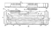
- FIG. 1is a simplified orthogonal view of a fuel processor and integrated fuel cell stack including a plurality of fluidic channels, according to the present invention
- FIG. 2is a simplified sectional view of a fuel processor and integrated fuel cell stack according to the present invention
- FIG. 3is a simplified sectional view of an alternative embodiment of the fuel processor and integrated fuel cell stack of the present invention.
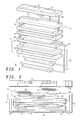
- FIG. 4is a simplified sectional view of a thermally conductive structure according to the present invention.
- FIGS. 5 and 6are simplified sectional views of alternative embodiments of thermally controlled vaporizer/reaction zone channels according to the present invention.
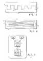
- FIG. 7is a simplified flow diagram of the method of reforming fuel according to the present invention.
- FIG. 8is a schematic diagram of the fuel cell system integrated with a fuel reformer according to the present invention.
- Fuel processor 10is comprised of a three-dimensional multilayer ceramic structure 12 .
- Ceramic structure 12is formed utilizing multi-layer laminate ceramic technology.
- Structure 12is typically formed in component parts which are then sintered in such a way as to provide for a monolithic structure.
- Ceramic structure 12has defined therein a fuel reformer, or fuel processor, generally referenced 14 .
- Fuel reformer 14includes a vaporization chamber, or vaporization zone, 16 , a reaction chamber, or reaction zone, 18 , and an integrated heat source, 28 .
- Ceramic structure 12further includes at least one fuel inlet channel 20 in communication with a liquid fuel source of a combination solution methanol/water source 24 and a pure methanol source 26 and a hydrogen enriched gas outlet channel 22 .
- integrated heater 28is described as a chemical heater, including a catalyst and arranged so as to oxidize fuel to produce heat, but it should be understood that the integration of an electrical heater is anticipated by this disclosure.
- Chemical heater 28includes an air port 40 for providing oxygen for oxidation of methanol/water 24 and/or pure methanol 26 and an inlet channel 20 , for providing methanol/water 24 and/or pure methanol 26 to heater 28 .
- Output from fuel vaporizer zone 16travels via channel 30 to reaction zone 18 and then through hydrogen enriched gas outlet channel 22 to a fuel cell stack 32 to supply hydrogen fuel to stack 32 .
- Spent gases from the fuel cell 32are directed through a waste heat recovery zone 34 to capture the heat from the spent gases.
- Spent gases from chemical heater 28also travel through this zone for the same reason.
- An efficient thermal insulator 36is positioned under fuel vaporizer zone 16 to keep outer temperatures low for packaging and also to keep heat localized to the fuel reformer system.
- high temperature fuel cell 32is integrated with fuel reformer 14 .
- This particular fuel cell designallows for the operation of the fuel cell at a temperature ranging from 140-200° C.
- Fuel vaporizer zone 16operates at a temperature ranging from 120-160° C. and the steam reforming reaction zone 18 operates at a temperature ranging from 200-300° C.
- an exhaust gas vent 38for the venting of exhaust gases generated by device 10 , an air inlet 40 and a top current collector or cap 42 (as illustrated in FIG. 2 ).
- a heater using the water and methanol solutionis suitable for practical applications, and would permit a simple common fuel reservoir for feeding the heater and reformer chambers. In this instance, the fuel delivery would be split into two chambers, the chemical heater 28 and fuel vaporizer 16 .
- reaction zone 18surrounds the chemical heater 28 on both sides (top and bottom).
- reaction zone 18can be positioned below heater 28 and the fuel vaporizer zone 16 on top of the chemical heater 28 .
- chemical heater 28can alternatively be an electrical heater (not shown).
- FIGS. 1 and 2a design in which a fuel cell is not integrated with reformer 14 is additionally anticipated and illustrate in FIG. 3, discussed presently.
- FIGS. 1 and 2when fuel cell stack 32 is integrated with fuel reformer 14 , advantage can be taken of the heat of the substrate to operate high temperature fuel cell stack 32 .
- external connectioncan be made to connect the stand alone fuel reformer to a traditional fuel cell stack for higher power applications.
- reformer 10 ′includes a combination fuel comprised of liquid methanol and water, input through inlet 20 ′, vaporizer 16 ′, electrical heaters 28 ′, reaction zone 18 ′, and hydrogen enriched fuel outlet 22 ′.
- Device 10 ′operates generally similar to device 10 as illustrated in FIGS. 1 and 2, except in this particular embodiment, and hydrogen enriched fuel outlet 22 ′ serves to direct the reformed hydrogen fuel toward an externally connected fuel cell (not shown).
- thermal conductive structure 30is generally utilized for transfer of heat efficiently between chemical heater 28 and fuel vaporizer zone 16 and reaction zone 18 , as well as between waste heat recovery 22 and reaction zone 18 .
- thermal conductive structure 30includes multi-layer ceramic layers 52 used in the fabrication of the monolithic structure 12 .
- chemical heater section 28 and reaction zone chamber 18Identified is chemical heater section 28 and reaction zone chamber 18 .
- Thermally conductive thick-film metal vias 54thermally couple the top and bottom sections efficiently for good heat transfer.
- a thick-film metal layer 55in intimate contact with chemical heater zone 28 and reaction zone 18 spreads and uniformly heats these sections.
- serpentine channel 60that is typically filled or coated with an inert porous ceramic material for thermal control.
- vaporizer 16can be formed of a multiplicity of parallel channels 61 , with an inert porous ceramic material for thermal control, in microfluidic communication with a porous diffuser 113 .
- serpentine channel 60 or parallel channel 61includes a combined single liquid inlet feed 62 at one end and combining into a single vapor outlet at the other end 64 .
- Serpentine channels 60 and parallel channels 61are formed in the multi-layer ceramic structure, previously identified as 12 .
- Reaction zone 18includes similarly designed channels and features as found in the vaporizer zone, discussed above. More particularly, reaction zone 18 includes a reforming catalyst. The catalyst is present as channel wall coatings or as a porous packed bed of catalyst particles.
- One design goalis to reduce the dimensionality of the reactor channels to the order of a gas diffusion length and control gas residence times, or gas space velocity, that are favorable to reaction kinetics.
- a multiplicity of parallel reactor channels, generally similar to channels 61provide for high gas throughput and minimizes back pressure issues as related to channel blockage.
- vaporizer zone 16 and reaction zone 18may include in addition to, or in lieu of, serpentine channels 60 and parallel channels 61 , any number of cavities or chambers, or any combination of channels, cavities, or chambers, thereof.
- FIG. 7Illustrated in FIG. 7 in a simplified flow chart diagram, is the chemical reaction that takes place in device 10 , and more particularly in reformer 14 of device 10 .
- methanol 70 and water 72are input into a steam reformer 74 , generally similar to reformer 14 of FIGS. 1 and 2.
- Steam reformer 74operates at a temperature of approximately 250° C. to reform the input methanol 70 and water 72 into a reformed gas mixture, generally referred to as the hydrogen enriched gas.
- a catalystsuch as copper oxide, zinc oxide, or copper zinc oxide, the methanol 70 and water 72 solution is reformed into hydrogen, carbon dioxide, and some carbon monoxide.
- Steam reformer 74operates in conjunction with an optional carbon monoxide cleanup 76 , that in the presence of a preferential oxidation catalyst and air (or O 2 ), reforms a large percentage of the present carbon monoxide into carbon dioxide.
- This reformed gas mixturesupplies fuel through fuel output 78 to a fuel cell, generally similar to fuel cell 32 of FIGS. 1 and 2.
- FIG. 8Illustrated in FIG. 8 is a schematic diagram of fuel cell system 10 with integrated fuel reformer 14 .
- fuel cell 32can be operated directly using output 22 from fuel reformer 14 without CO clean up.
- fuel cell 32is a high temperature fuel cell.
- An advantage of the integration of a traditional fuel cell stack 32 with the fuel processor 14is the ability to operate fuel cell 32 at higher temperatures of 140-200° C. by taking advantage of the heat from reformer 14 .
- High temperature fuel cell membranessuch as PBI (polybenzimidazole), or similar polymer composition known as ABPBI can be used in these applications. These fuel cell membranes operating at temperatures greater than 120° C.
- a fuel processorincluding a ceramic carrier defining a reaction zone including a catalyst.
- the ceramic carrierfurther includes a heat source thermally coupled to the reaction zone chamber.
- An inlet channelis supplied for input of the liquid fuel to the fuel processor and an outlet channel is supplied for the output of the reformed gas mixture.
- the fuel processor deviceis formed as a monolithically integrated structure, generally comprised of a plurality of thin ceramic layers assembled and then sintered in such a way as to provide for the closed heating zones in which the encapsulated catalysts reforms the inlet fuel into mostly hydrogen gas suitable for use with a fuel cell stack.
Landscapes
- Chemical & Material Sciences (AREA)
- Chemical Kinetics & Catalysis (AREA)
- Engineering & Computer Science (AREA)
- Organic Chemistry (AREA)
- Electrochemistry (AREA)
- Sustainable Energy (AREA)
- General Chemical & Material Sciences (AREA)
- Sustainable Development (AREA)
- Life Sciences & Earth Sciences (AREA)
- Manufacturing & Machinery (AREA)
- Inorganic Chemistry (AREA)
- General Health & Medical Sciences (AREA)
- Health & Medical Sciences (AREA)
- Combustion & Propulsion (AREA)
- Hydrogen, Water And Hydrids (AREA)
- Fuel Cell (AREA)
- Catalysts (AREA)
- Inert Electrodes (AREA)
- Organic Low-Molecular-Weight Compounds And Preparation Thereof (AREA)
Abstract
Description
Claims (21)
Priority Applications (13)
| Application Number | Priority Date | Filing Date | Title |
|---|---|---|---|
| US09/649,553US6569553B1 (en) | 2000-08-28 | 2000-08-28 | Fuel processor with integrated fuel cell utilizing ceramic technology |
| TW090121077ATW515127B (en) | 2000-08-28 | 2001-08-27 | Fuel processor with integrated fuel cell utilizing ceramic technology |
| CNB018165273ACN100361339C (en) | 2000-08-28 | 2001-08-28 | Fuel processor with integrated fuel cell utilizing ceramic technology |
| JP2002524246AJP4969762B2 (en) | 2000-08-28 | 2001-08-28 | Fuel processor having an integrated fuel cell stack |
| KR1020037002910AKR100760842B1 (en) | 2000-08-28 | 2001-08-28 | Fuel processor with integrated fuel cell utilizing ceramic technology |
| BR0113593-7ABR0113593A (en) | 2000-08-28 | 2001-08-28 | Fuel processor and integrated fuel cell |
| RU2003108499/09ARU2003108499A (en) | 2000-08-28 | 2001-08-28 | DEVICE FOR FUEL PROCESSING WITH INTEGRATED FUEL ELEMENT, PRODUCED BY CERAMICS PRODUCTION TECHNOLOGY |
| EP01966398AEP1346428B1 (en) | 2000-08-28 | 2001-08-28 | Fuel processor with integrated fuel cell utilizing ceramic technology |
| AU2001286917AAU2001286917A1 (en) | 2000-08-28 | 2001-08-28 | Fuel processor with integrated fuel cell utilizing ceramic technology |
| AT01966398TATE441220T1 (en) | 2000-08-28 | 2001-08-28 | INTEGRATED FUEL PROCESSOR FUEL CELL SYSTEM USING CERAMIC TECHNOLOGY |
| DE60139713TDE60139713D1 (en) | 2000-08-28 | 2001-08-28 | INTEGRATED FUEL PROCESSOR FUEL CELL SYSTEM USING CERAMIC TECHNOLOGY |
| PCT/US2001/026980WO2002019452A2 (en) | 2000-08-28 | 2001-08-28 | Fuel processor with integrated fuel cell utilizing ceramic technology |
| ZA200301549AZA200301549B (en) | 2000-08-28 | 2003-02-25 | Fuel processor with integrated fuel cell utilizing ceramic technology. |
Applications Claiming Priority (1)
| Application Number | Priority Date | Filing Date | Title |
|---|---|---|---|
| US09/649,553US6569553B1 (en) | 2000-08-28 | 2000-08-28 | Fuel processor with integrated fuel cell utilizing ceramic technology |
Publications (1)
| Publication Number | Publication Date |
|---|---|
| US6569553B1true US6569553B1 (en) | 2003-05-27 |
Family
ID=24605297
Family Applications (1)
| Application Number | Title | Priority Date | Filing Date |
|---|---|---|---|
| US09/649,553Expired - LifetimeUS6569553B1 (en) | 2000-08-28 | 2000-08-28 | Fuel processor with integrated fuel cell utilizing ceramic technology |
Country Status (13)
| Country | Link |
|---|---|
| US (1) | US6569553B1 (en) |
| EP (1) | EP1346428B1 (en) |
| JP (1) | JP4969762B2 (en) |
| KR (1) | KR100760842B1 (en) |
| CN (1) | CN100361339C (en) |
| AT (1) | ATE441220T1 (en) |
| AU (1) | AU2001286917A1 (en) |
| BR (1) | BR0113593A (en) |
| DE (1) | DE60139713D1 (en) |
| RU (1) | RU2003108499A (en) |
| TW (1) | TW515127B (en) |
| WO (1) | WO2002019452A2 (en) |
| ZA (1) | ZA200301549B (en) |
Cited By (44)
| Publication number | Priority date | Publication date | Assignee | Title |
|---|---|---|---|---|
| US20030013002A1 (en)* | 2001-07-16 | 2003-01-16 | The Regents Of The University Of California | Method for fabrication of elecrodes |
| US20030039874A1 (en)* | 1999-02-01 | 2003-02-27 | The Regents Of The University Of California | MEMS-based thin-film fuel cells |
| US20030064275A1 (en)* | 2001-09-28 | 2003-04-03 | The Regents Of The University Of California | Method of forming a package for mems-based fuel cell |
| US20030103878A1 (en)* | 2001-12-05 | 2003-06-05 | The Regents Of The University Of California | Chemical microreactor and method thereof |
| US20030203271A1 (en)* | 2002-04-24 | 2003-10-30 | The Regents Of The University Of California | Microfluidic fuel cell systems with embedded materials and structures and method thereof |
| US20030219927A1 (en)* | 2002-05-15 | 2003-11-27 | Ryu Sang Hyun | Solder balls and conductive wires for a semiconductor package, and an improved manufacturing method, and evaporation method therefor |
| US20040062965A1 (en)* | 2002-09-30 | 2004-04-01 | The Regents Of The University Of California | Bonded polyimide fuel cell package and method thereof |
| US20040179980A1 (en)* | 2002-12-20 | 2004-09-16 | Pattekar Ashish V. | Microreactor and method of use to produce hydrogen by methanol reforming |
| US20040191591A1 (en)* | 2003-03-25 | 2004-09-30 | Casio Computer Co., Ltd. | Reforming apparatus |
| US20040228211A1 (en)* | 2003-05-13 | 2004-11-18 | Koripella Chowdary R. | Internal micromixer |
| US20050008911A1 (en)* | 2003-06-27 | 2005-01-13 | Ultracell Corporation | Micro fuel cell thermal management |
| US20050008909A1 (en)* | 2003-06-27 | 2005-01-13 | Ultracell Corporation | Efficient micro fuel cell systems and methods |
| US20050005521A1 (en)* | 2003-06-27 | 2005-01-13 | Ultracell Corporation | Fuel processor dewar and methods |
| US20050008908A1 (en)* | 2003-06-27 | 2005-01-13 | Ultracell Corporation | Portable fuel cartridge for fuel cells |
| US20050016832A1 (en)* | 2002-07-01 | 2005-01-27 | The Regents Of The University Of California | Vapor-deposited porous films for energy conversion |
| US20050244684A1 (en)* | 2004-04-30 | 2005-11-03 | Koripella Chowdary R | Solid oxide fuel cell portable power source |
| US20050255368A1 (en)* | 2004-05-12 | 2005-11-17 | Ultracell Corporation, A California Corporation | High surface area micro fuel cell architecture |
| US20060029848A1 (en)* | 2004-08-06 | 2006-02-09 | Ultracell Corporation | Method and system for controlling fluid delivery in a fuel cell |
| US7048897B1 (en)* | 2000-08-28 | 2006-05-23 | Motorola, Inc. | Hydrogen generator utilizing ceramic technology |
| US20060127733A1 (en)* | 2004-06-25 | 2006-06-15 | Ultracell Corporation | Fuel cartridge connectivity |
| US20060127719A1 (en)* | 2003-06-27 | 2006-06-15 | Ultracell Corporation, A California Corporation | Heat efficient portable fuel cell systems |
| US20060127711A1 (en)* | 2004-06-25 | 2006-06-15 | Ultracell Corporation, A California Corporation | Systems and methods for fuel cartridge distribution |
| US20060134470A1 (en)* | 2004-12-21 | 2006-06-22 | Ultracell Corporation | Compact fuel cell package |
| US20060156627A1 (en)* | 2003-06-27 | 2006-07-20 | Ultracell Corporation | Fuel processor for use with portable fuel cells |
| US20060194082A1 (en)* | 2005-02-02 | 2006-08-31 | Ultracell Corporation | Systems and methods for protecting a fuel cell |
| US20060210845A1 (en)* | 2005-03-16 | 2006-09-21 | Ju-Yong Kim | Stack having reforming function and fuel cell system having the same |
| US7122261B2 (en) | 2003-02-21 | 2006-10-17 | The Regents Of The University Of California | Metal hydride fuel storage and method thereof |
| US20060234095A1 (en)* | 2005-04-13 | 2006-10-19 | Sang-Jun Kong | Plate type reformer and fuel cell system including the reformer |
| US20060257707A1 (en)* | 2004-06-25 | 2006-11-16 | Ultracell Corporation | Disposable component on a fuel cartridge and for use with a portable fuel cell system |
| US20060277827A1 (en)* | 2005-06-09 | 2006-12-14 | Casio Computer Co., Ltd. | Reactor |
| US20070022825A1 (en)* | 2005-07-29 | 2007-02-01 | Stephen Samms | Fluidic oscillation flow meter |
| US20070087235A1 (en)* | 2005-10-17 | 2007-04-19 | Samsung Electro-Mechanics Co., Ltd. | Multi-layered thin film hydrogen fuel cell system |
| US20070243447A1 (en)* | 2006-04-18 | 2007-10-18 | Samsung Electro-Mechanics Co., Ltd. | High capacity micro fuel cell system |
| US20080035252A1 (en)* | 2006-02-27 | 2008-02-14 | Mallery Carl F | Solid hydrogen fuel elements and methods of making the same |
| US20080057360A1 (en)* | 2003-06-27 | 2008-03-06 | Ultracell Corporation | Portable systems for engine block |
| US20080187797A1 (en)* | 2006-07-10 | 2008-08-07 | Protonex Technology Corporation | Fuel processor for fuel cell systems |
| US20090023050A1 (en)* | 2007-07-19 | 2009-01-22 | Caine Finnerty | Internal reforming solid oxide fuel cells |
| US20090035620A1 (en)* | 2007-08-03 | 2009-02-05 | Caine Finnerty | Solid oxide fuel cell systems with improved gas channeling and heat exchange |
| WO2010022732A1 (en)* | 2008-08-25 | 2010-03-04 | Dantherm Power A/S | Fuel cell system and method of operating such fuel cell system |
| US20100086813A1 (en)* | 2006-08-30 | 2010-04-08 | Kyocera Corporation | Reaction Apparatus, Fuel Cell System and Electronic Device |
| US20100097311A1 (en)* | 2006-08-30 | 2010-04-22 | Kyocera Corporation | Reaction Apparatus, Fuel Cell System and Electronic Device |
| US20100112394A1 (en)* | 2006-08-30 | 2010-05-06 | Kyocera Corporation | Reaction Apparatus, Fuel Cell System and Electronic Device |
| US8821832B2 (en) | 2003-06-27 | 2014-09-02 | UltraCell, L.L.C. | Fuel processor for use with portable fuel cells |
| US10367208B2 (en) | 2015-05-06 | 2019-07-30 | Robert E. Buxbaum | High efficiency fuel reforming and water use in a high temperature fuel-cell system and process for the such thereof |
Families Citing this family (14)
| Publication number | Priority date | Publication date | Assignee | Title |
|---|---|---|---|---|
| JP4075435B2 (en)* | 2002-03-29 | 2008-04-16 | カシオ計算機株式会社 | Chemical reactor and fuel cell system |
| US7169367B2 (en) | 2002-04-05 | 2007-01-30 | Casio Computer Co., Ltd. | Chemical reaction apparatus and power supply system |
| CA2452657C (en)* | 2003-02-18 | 2009-03-03 | Sulzer Markets And Technology Ag | A power source with solid oxide fuel cells |
| KR100599687B1 (en)* | 2004-06-29 | 2006-07-13 | 삼성에스디아이 주식회사 | Fuel cell system and reformer used therein |
| JP4939148B2 (en)* | 2006-08-30 | 2012-05-23 | 京セラ株式会社 | Reactor, fuel cell system and electronic device |
| JP4887102B2 (en)* | 2006-08-30 | 2012-02-29 | 京セラ株式会社 | Reactor, fuel cell system and electronic device |
| JP4552915B2 (en)* | 2006-09-01 | 2010-09-29 | カシオ計算機株式会社 | Reforming apparatus and power generation system |
| EP1909350B1 (en) | 2006-10-06 | 2010-12-08 | STMicroelectronics Srl | Micro fuel cell system fed with hydrogen produced by decomposition of sodium borohydride in a microreactor |
| US8232010B2 (en) | 2006-10-06 | 2012-07-31 | Stmicroelectronics S.R.L. | Process and corresponding apparatus for continuously producing gaseous hydrogen to be supplied to micro fuel cells and integrated system for producing electric energy |
| US20080245424A1 (en)* | 2007-02-22 | 2008-10-09 | Jacobsen Stephen C | Micro fluid transfer system |
| KR101200930B1 (en) | 2010-05-04 | 2012-11-13 | 한국과학기술연구원 | Micro-macro channel reactor |
| DE102013012731A1 (en)* | 2013-08-01 | 2015-02-05 | Krohne Messtechnik Gmbh | Process for the preparation of a gas converter and corresponding gas converter |
| DE102016117998A1 (en)* | 2016-09-23 | 2018-03-29 | Fraunhofer-Gesellschaft zur Förderung der angewandten Forschung e.V. | Device for the detection of organic compounds |
| CN115228103A (en)* | 2022-07-06 | 2022-10-25 | 彩源科技股份有限公司 | Ammonia water treatment device |
Citations (2)
| Publication number | Priority date | Publication date | Assignee | Title |
|---|---|---|---|---|
| US4816353A (en)* | 1986-05-14 | 1989-03-28 | International Fuel Cells Corporation | Integrated fuel cell and fuel conversion apparatus |
| US5858314A (en)* | 1996-04-12 | 1999-01-12 | Ztek Corporation | Thermally enhanced compact reformer |
Family Cites Families (11)
| Publication number | Priority date | Publication date | Assignee | Title |
|---|---|---|---|---|
| JPS5924721B2 (en)* | 1979-07-12 | 1984-06-12 | 日産自動車株式会社 | Alcohol reformer |
| JPH02186565A (en)* | 1989-01-12 | 1990-07-20 | Sanyo Electric Co Ltd | molten carbonate fuel cell |
| JPH0562701A (en)* | 1991-08-30 | 1993-03-12 | Nippon Telegr & Teleph Corp <Ntt> | Solid oxide fuel cell |
| JPH06287062A (en)* | 1993-03-31 | 1994-10-11 | Toshiba Corp | Reinforced SiC-based ceramic member |
| JP3700162B2 (en)* | 1994-05-20 | 2005-09-28 | 石川島播磨重工業株式会社 | Integrated fuel cell power generator |
| JP3440551B2 (en)* | 1994-06-09 | 2003-08-25 | 三菱電機株式会社 | Fuel reformer and method of operating fuel reformer |
| JPH08138693A (en)* | 1994-11-01 | 1996-05-31 | Matsushita Electric Ind Co Ltd | Fuel cell and power generator using the same |
| DE19716438A1 (en)* | 1997-04-18 | 1998-10-22 | Heitzer Joerg Dr | Cooling for fuel cell |
| JP3743119B2 (en)* | 1997-06-03 | 2006-02-08 | ダイキン工業株式会社 | Fuel cell power generation system |
| JP4305973B2 (en)* | 1997-07-23 | 2009-07-29 | トヨタ自動車株式会社 | Fuel reformer |
| BR9911883B1 (en)* | 1998-07-08 | 2009-01-13 | fuel reforming device. |
- 2000
- 2000-08-28USUS09/649,553patent/US6569553B1/ennot_activeExpired - Lifetime
- 2001
- 2001-08-27TWTW090121077Apatent/TW515127B/ennot_activeIP Right Cessation
- 2001-08-28ATAT01966398Tpatent/ATE441220T1/ennot_activeIP Right Cessation
- 2001-08-28AUAU2001286917Apatent/AU2001286917A1/ennot_activeAbandoned
- 2001-08-28DEDE60139713Tpatent/DE60139713D1/ennot_activeExpired - Lifetime
- 2001-08-28RURU2003108499/09Apatent/RU2003108499A/ennot_activeApplication Discontinuation
- 2001-08-28WOPCT/US2001/026980patent/WO2002019452A2/enactiveApplication Filing
- 2001-08-28BRBR0113593-7Apatent/BR0113593A/ennot_activeIP Right Cessation
- 2001-08-28CNCNB018165273Apatent/CN100361339C/ennot_activeExpired - Fee Related
- 2001-08-28KRKR1020037002910Apatent/KR100760842B1/ennot_activeExpired - Fee Related
- 2001-08-28EPEP01966398Apatent/EP1346428B1/ennot_activeExpired - Lifetime
- 2001-08-28JPJP2002524246Apatent/JP4969762B2/ennot_activeExpired - Fee Related
- 2003
- 2003-02-25ZAZA200301549Apatent/ZA200301549B/enunknown
Patent Citations (2)
| Publication number | Priority date | Publication date | Assignee | Title |
|---|---|---|---|---|
| US4816353A (en)* | 1986-05-14 | 1989-03-28 | International Fuel Cells Corporation | Integrated fuel cell and fuel conversion apparatus |
| US5858314A (en)* | 1996-04-12 | 1999-01-12 | Ztek Corporation | Thermally enhanced compact reformer |
Cited By (123)
| Publication number | Priority date | Publication date | Assignee | Title |
|---|---|---|---|---|
| US20040043273A1 (en)* | 1999-02-01 | 2004-03-04 | The Regents Of The University Of California | Solid oxide MEMS-based fuel cells |
| US20030039874A1 (en)* | 1999-02-01 | 2003-02-27 | The Regents Of The University Of California | MEMS-based thin-film fuel cells |
| US7189471B2 (en) | 1999-02-01 | 2007-03-13 | The Regents Of The University Of California | Solid oxide MEMS-based fuel cells |
| US20040048128A1 (en)* | 1999-02-01 | 2004-03-11 | The Regents Of The University Of California | Solid polymer mems-based fuel cells |
| US7361424B2 (en) | 1999-02-01 | 2008-04-22 | The Regents Of The University Of California | Solid polymer MEMS-based fuel cells |
| US7048897B1 (en)* | 2000-08-28 | 2006-05-23 | Motorola, Inc. | Hydrogen generator utilizing ceramic technology |
| US6753036B2 (en) | 2001-07-16 | 2004-06-22 | The Regents Of The University Of California | Method for fabrication of electrodes |
| US20030013002A1 (en)* | 2001-07-16 | 2003-01-16 | The Regents Of The University Of California | Method for fabrication of elecrodes |
| US20030064275A1 (en)* | 2001-09-28 | 2003-04-03 | The Regents Of The University Of California | Method of forming a package for mems-based fuel cell |
| US6821666B2 (en) | 2001-09-28 | 2004-11-23 | The Regents Of The Univerosity Of California | Method of forming a package for mems-based fuel cell |
| US7534402B2 (en) | 2001-12-05 | 2009-05-19 | Lawrence Livermore National Security, Llc | Method for forming a chemical microreactor |
| US20030103878A1 (en)* | 2001-12-05 | 2003-06-05 | The Regents Of The University Of California | Chemical microreactor and method thereof |
| US20060057039A1 (en)* | 2001-12-05 | 2006-03-16 | The Regents Of The University Of California | Chemical microreactor and method thereof |
| US6960235B2 (en)* | 2001-12-05 | 2005-11-01 | The Regents Of The University Of California | Chemical microreactor and method thereof |
| US20030203271A1 (en)* | 2002-04-24 | 2003-10-30 | The Regents Of The University Of California | Microfluidic fuel cell systems with embedded materials and structures and method thereof |
| US6921603B2 (en) | 2002-04-24 | 2005-07-26 | The Regents Of The University Of California | Microfluidic fuel cell systems with embedded materials and structures and method thereof |
| US20030219927A1 (en)* | 2002-05-15 | 2003-11-27 | Ryu Sang Hyun | Solder balls and conductive wires for a semiconductor package, and an improved manufacturing method, and evaporation method therefor |
| US20050016832A1 (en)* | 2002-07-01 | 2005-01-27 | The Regents Of The University Of California | Vapor-deposited porous films for energy conversion |
| US6913998B2 (en) | 2002-07-01 | 2005-07-05 | The Regents Of The University Of California | Vapor-deposited porous films for energy conversion |
| US20040062965A1 (en)* | 2002-09-30 | 2004-04-01 | The Regents Of The University Of California | Bonded polyimide fuel cell package and method thereof |
| US6960403B2 (en) | 2002-09-30 | 2005-11-01 | The Regents Of The University Of California | Bonded polyimide fuel cell package and method thereof |
| US8007626B2 (en) | 2002-12-20 | 2011-08-30 | Lehigh University | Micro-fluidic interconnector |
| US7541007B2 (en) | 2002-12-20 | 2009-06-02 | Lehigh University | Microreactor and method of use to produce hydrogen by methanol reforming |
| US20040179980A1 (en)* | 2002-12-20 | 2004-09-16 | Pattekar Ashish V. | Microreactor and method of use to produce hydrogen by methanol reforming |
| US20090242116A1 (en)* | 2002-12-20 | 2009-10-01 | Lehigh University | Micro-fluidic interconnector |
| US20070031586A1 (en)* | 2003-02-21 | 2007-02-08 | The Regents Of The University Of California | Metal hydride fuel storage and method thereof |
| US7122261B2 (en) | 2003-02-21 | 2006-10-17 | The Regents Of The University Of California | Metal hydride fuel storage and method thereof |
| US7527659B2 (en) | 2003-02-21 | 2009-05-05 | Lawrence Livermore National Security, Llc | Metal hydride fuel storage and method thereof |
| US7344572B2 (en) | 2003-03-25 | 2008-03-18 | Casio Computer Co., Ltd. | Reforming apparatus |
| US20040191591A1 (en)* | 2003-03-25 | 2004-09-30 | Casio Computer Co., Ltd. | Reforming apparatus |
| US20040228211A1 (en)* | 2003-05-13 | 2004-11-18 | Koripella Chowdary R. | Internal micromixer |
| US7622207B2 (en) | 2003-06-27 | 2009-11-24 | Ultracell Corporation | Fuel cell cartridge with reformate filtering |
| US20050014059A1 (en)* | 2003-06-27 | 2005-01-20 | Ultracell Corporation | Micro fuel cell architecture |
| US20060024553A1 (en)* | 2003-06-27 | 2006-02-02 | Ultracell Corporation | Hot swappable fuel cell system |
| US20060024543A1 (en)* | 2003-06-27 | 2006-02-02 | Ultracell Corporation | Fuel cell system with controller and smart cartridge |
| US20060021882A1 (en)* | 2003-06-27 | 2006-02-02 | Ultracell Corporation | Fire retardant fuel cell cartridge |
| US7807130B2 (en) | 2003-06-27 | 2010-10-05 | Ultracell Corporation | Fuel processor dewar and methods |
| US20060014070A1 (en)* | 2003-06-27 | 2006-01-19 | Ultracell Corporation | Hydrogen fuel source refiller |
| US20060070891A1 (en)* | 2003-06-27 | 2006-04-06 | Ultracell Corporation | Fuel cell cartridge filters and pressure relief |
| US20060073365A1 (en)* | 2003-06-27 | 2006-04-06 | Ultracell Corporation | Fuel cell cartridge with reformate filtering |
| US20060008687A1 (en)* | 2003-06-27 | 2006-01-12 | Ultracell Corporation | Fuel cell system internal to portable computer |
| US7763368B2 (en) | 2003-06-27 | 2010-07-27 | Ultracell Corporation | Efficient micro fuel cell systems and methods |
| US20060127719A1 (en)* | 2003-06-27 | 2006-06-15 | Ultracell Corporation, A California Corporation | Heat efficient portable fuel cell systems |
| US20110020197A1 (en)* | 2003-06-27 | 2011-01-27 | Ultracell Corporation | Portable fuel processor |
| US20100047139A1 (en)* | 2003-06-27 | 2010-02-25 | Ultracell Corporation | Fuel processor for use with portable cells |
| US20060156627A1 (en)* | 2003-06-27 | 2006-07-20 | Ultracell Corporation | Fuel processor for use with portable fuel cells |
| US7666539B2 (en) | 2003-06-27 | 2010-02-23 | Ultracell Corporation | Heat efficient portable fuel cell systems |
| US7655337B2 (en) | 2003-06-27 | 2010-02-02 | Ultracell Corporation | Micro fuel cell thermal management |
| US20050008909A1 (en)* | 2003-06-27 | 2005-01-13 | Ultracell Corporation | Efficient micro fuel cell systems and methods |
| US7604673B2 (en) | 2003-06-27 | 2009-10-20 | Ultracell Corporation | Annular fuel processor and methods |
| US20050005521A1 (en)* | 2003-06-27 | 2005-01-13 | Ultracell Corporation | Fuel processor dewar and methods |
| US7585581B2 (en) | 2003-06-27 | 2009-09-08 | Ultracell Corporation | Micro fuel cell architecture |
| US20050008908A1 (en)* | 2003-06-27 | 2005-01-13 | Ultracell Corporation | Portable fuel cartridge for fuel cells |
| US20060014069A1 (en)* | 2003-06-27 | 2006-01-19 | Ultracell Corporation | Smart fuel cell cartridge |
| US20050011125A1 (en)* | 2003-06-27 | 2005-01-20 | Ultracell Corporation, A California Corporation | Annular fuel processor and methods |
| US8821832B2 (en) | 2003-06-27 | 2014-09-02 | UltraCell, L.L.C. | Fuel processor for use with portable fuel cells |
| US20050186455A1 (en)* | 2003-06-27 | 2005-08-25 | Ultracell Corporation, A California Corporation | Micro fuel cell system start up and shut down systems and methods |
| US20090123797A1 (en)* | 2003-06-27 | 2009-05-14 | Ultracell Corporation | Efficient micro fuel cell systems and methods |
| US8318368B2 (en) | 2003-06-27 | 2012-11-27 | UltraCell, L.L.C. | Portable systems for engine block |
| US8043757B2 (en) | 2003-06-27 | 2011-10-25 | UltraCell Acquisition Company, L.L.C. | Efficient micro fuel cell systems and methods |
| US7276096B2 (en) | 2003-06-27 | 2007-10-02 | Ultracell Corporation | Fuel processor dewar and methods |
| US20050008911A1 (en)* | 2003-06-27 | 2005-01-13 | Ultracell Corporation | Micro fuel cell thermal management |
| US7291191B2 (en) | 2003-06-27 | 2007-11-06 | Ultracell Corporation | Fuel cell cartridge filters and pressure relief |
| US20070269703A1 (en)* | 2003-06-27 | 2007-11-22 | Ultracell Corporation | Micro fuel cell architecture |
| US20070292729A1 (en)* | 2003-06-27 | 2007-12-20 | Ultracell Corporation | Heat efficient portable fuel cell systems |
| US20070294941A1 (en)* | 2003-06-27 | 2007-12-27 | Ultracell Corporation | Fuel processor dewar and methods |
| US20080008646A1 (en)* | 2003-06-27 | 2008-01-10 | Ultracell Corporation | Portable fuel processor |
| US20080016767A1 (en)* | 2003-06-27 | 2008-01-24 | Ultracell Corporation | Fuel processor for use with portable fuel cells |
| US20080017647A1 (en)* | 2003-06-27 | 2008-01-24 | Ultracell Corporation | Systems and methods for fuel cartridge distribution |
| US7807129B2 (en) | 2003-06-27 | 2010-10-05 | Ultracell Corporation | Portable fuel processor |
| US20080038601A1 (en)* | 2003-06-27 | 2008-02-14 | Ultracell Corporation | Efficient micro fuel cell systems and methods |
| US20090071072A1 (en)* | 2003-06-27 | 2009-03-19 | Ultracell Corporation | Planar micro fuel processor |
| US20080057360A1 (en)* | 2003-06-27 | 2008-03-06 | Ultracell Corporation | Portable systems for engine block |
| US20050022448A1 (en)* | 2003-06-27 | 2005-02-03 | Ultracell Corporation | Planar micro fuel processor |
| US20050014040A1 (en)* | 2003-06-27 | 2005-01-20 | Ultracell Corporation | Fuel preheat in fuel cells and portable electronics |
| US7935452B2 (en) | 2003-06-27 | 2011-05-03 | Ultracell Corporation | Micro fuel cell architecture |
| US20080169207A1 (en)* | 2003-06-27 | 2008-07-17 | Ultracell Corporation | Fuel cell cartridge filters and pressure relief |
| US7401712B2 (en) | 2003-06-27 | 2008-07-22 | Ultracell Corporation | Smart fuel cell cartridge |
| US7943263B2 (en) | 2003-06-27 | 2011-05-17 | Ultracell Corporation | Heat efficient portable fuel cell systems |
| US7462208B2 (en) | 2003-06-27 | 2008-12-09 | Ultracell Corporation | Planar micro fuel processor |
| US7335432B2 (en) | 2004-04-30 | 2008-02-26 | Motorola, Inc. | Solid oxide fuel cell portable power source |
| US20050244684A1 (en)* | 2004-04-30 | 2005-11-03 | Koripella Chowdary R | Solid oxide fuel cell portable power source |
| US20050255368A1 (en)* | 2004-05-12 | 2005-11-17 | Ultracell Corporation, A California Corporation | High surface area micro fuel cell architecture |
| US7648792B2 (en) | 2004-06-25 | 2010-01-19 | Ultracell Corporation | Disposable component on a fuel cartridge and for use with a portable fuel cell system |
| US20060127733A1 (en)* | 2004-06-25 | 2006-06-15 | Ultracell Corporation | Fuel cartridge connectivity |
| US20060127711A1 (en)* | 2004-06-25 | 2006-06-15 | Ultracell Corporation, A California Corporation | Systems and methods for fuel cartridge distribution |
| US20060257707A1 (en)* | 2004-06-25 | 2006-11-16 | Ultracell Corporation | Disposable component on a fuel cartridge and for use with a portable fuel cell system |
| US7968250B2 (en) | 2004-06-25 | 2011-06-28 | Ultracell Corporation | Fuel cartridge connectivity |
| US7205060B2 (en) | 2004-08-06 | 2007-04-17 | Ultracell Corporation | Method and system for controlling fluid delivery in a fuel cell |
| US20060029848A1 (en)* | 2004-08-06 | 2006-02-09 | Ultracell Corporation | Method and system for controlling fluid delivery in a fuel cell |
| US7892690B2 (en) | 2004-08-06 | 2011-02-22 | Ultracell Corporation | Methods for controlling fluid delivery in a micro fuel cell system |
| US7807313B2 (en) | 2004-12-21 | 2010-10-05 | Ultracell Corporation | Compact fuel cell package |
| US20060134470A1 (en)* | 2004-12-21 | 2006-06-22 | Ultracell Corporation | Compact fuel cell package |
| US20110020717A1 (en)* | 2004-12-21 | 2011-01-27 | Ultracell Corporation | Compact fuel cell package |
| US20060194082A1 (en)* | 2005-02-02 | 2006-08-31 | Ultracell Corporation | Systems and methods for protecting a fuel cell |
| US20080171239A1 (en)* | 2005-02-02 | 2008-07-17 | Ultracell Corporation | Systems and methods for protecting a fuel cell |
| US20060210845A1 (en)* | 2005-03-16 | 2006-09-21 | Ju-Yong Kim | Stack having reforming function and fuel cell system having the same |
| CN1835270B (en)* | 2005-03-16 | 2010-05-12 | 三星Sdi株式会社 | Battery stack with reforming function and fuel cell system with the same |
| US20060234095A1 (en)* | 2005-04-13 | 2006-10-19 | Sang-Jun Kong | Plate type reformer and fuel cell system including the reformer |
| US7976592B2 (en) | 2005-04-13 | 2011-07-12 | Samsung Sdi Co., Ltd. | Plate type reformer and fuel cell system including the reformer |
| US20060277827A1 (en)* | 2005-06-09 | 2006-12-14 | Casio Computer Co., Ltd. | Reactor |
| US7754161B2 (en) | 2005-06-09 | 2010-07-13 | Casio Computer Co., Ltd. | Reactor to reform fuel, including a low temperature reaction unit, a high temperature reaction unit, and a communicating tube via which the low and high temperature reaction units communicate with each other |
| WO2006132132A1 (en)* | 2005-06-09 | 2006-12-14 | Casio Computer Co., Ltd. | Reactor |
| US20070022825A1 (en)* | 2005-07-29 | 2007-02-01 | Stephen Samms | Fluidic oscillation flow meter |
| WO2007018716A1 (en)* | 2005-07-29 | 2007-02-15 | Motorola, Inc. | Fluidic oscillation flow meter |
| US7204156B2 (en)* | 2005-07-29 | 2007-04-17 | Motorola, Inc. | Fuel cell system having fluidic oscillation flow meter |
| CN101305267B (en)* | 2005-07-29 | 2012-07-18 | 摩托罗拉移动公司 | Fuel cell system with jet oscillating flowmeter |
| US20070087235A1 (en)* | 2005-10-17 | 2007-04-19 | Samsung Electro-Mechanics Co., Ltd. | Multi-layered thin film hydrogen fuel cell system |
| US20080035252A1 (en)* | 2006-02-27 | 2008-02-14 | Mallery Carl F | Solid hydrogen fuel elements and methods of making the same |
| US20070243447A1 (en)* | 2006-04-18 | 2007-10-18 | Samsung Electro-Mechanics Co., Ltd. | High capacity micro fuel cell system |
| US8080345B2 (en)* | 2006-04-18 | 2011-12-20 | Samsung Electro-Mechanics Co., Ltd. | High capacity micro fuel cell system |
| US20080187797A1 (en)* | 2006-07-10 | 2008-08-07 | Protonex Technology Corporation | Fuel processor for fuel cell systems |
| US20100112394A1 (en)* | 2006-08-30 | 2010-05-06 | Kyocera Corporation | Reaction Apparatus, Fuel Cell System and Electronic Device |
| US8382865B2 (en) | 2006-08-30 | 2013-02-26 | Kyocera Corporation | Reaction apparatus, fuel cell system and electronic device |
| US20100086813A1 (en)* | 2006-08-30 | 2010-04-08 | Kyocera Corporation | Reaction Apparatus, Fuel Cell System and Electronic Device |
| US20100097311A1 (en)* | 2006-08-30 | 2010-04-22 | Kyocera Corporation | Reaction Apparatus, Fuel Cell System and Electronic Device |
| US8382866B2 (en) | 2006-08-30 | 2013-02-26 | Kyocera Corporation | Reaction apparatus, fuel cell system and electronic device |
| US20090023050A1 (en)* | 2007-07-19 | 2009-01-22 | Caine Finnerty | Internal reforming solid oxide fuel cells |
| US8435683B2 (en) | 2007-07-19 | 2013-05-07 | Cp Sofc Ip, Llc | Internal reforming solid oxide fuel cells |
| US20090035620A1 (en)* | 2007-08-03 | 2009-02-05 | Caine Finnerty | Solid oxide fuel cell systems with improved gas channeling and heat exchange |
| US8309270B2 (en) | 2007-08-03 | 2012-11-13 | Cp Sofc Ip, Llc | Solid oxide fuel cell systems with improved gas channeling and heat exchange |
| WO2010022732A1 (en)* | 2008-08-25 | 2010-03-04 | Dantherm Power A/S | Fuel cell system and method of operating such fuel cell system |
| US10367208B2 (en) | 2015-05-06 | 2019-07-30 | Robert E. Buxbaum | High efficiency fuel reforming and water use in a high temperature fuel-cell system and process for the such thereof |
Also Published As
| Publication number | Publication date |
|---|---|
| DE60139713D1 (en) | 2009-10-08 |
| CN100361339C (en) | 2008-01-09 |
| TW515127B (en) | 2002-12-21 |
| ZA200301549B (en) | 2004-02-03 |
| KR20030028829A (en) | 2003-04-10 |
| WO2002019452A2 (en) | 2002-03-07 |
| KR100760842B1 (en) | 2007-10-04 |
| JP2004508670A (en) | 2004-03-18 |
| CN1689184A (en) | 2005-10-26 |
| AU2001286917A1 (en) | 2002-03-13 |
| RU2003108499A (en) | 2004-07-10 |
| BR0113593A (en) | 2004-06-08 |
| EP1346428A2 (en) | 2003-09-24 |
| WO2002019452A3 (en) | 2003-07-17 |
| JP4969762B2 (en) | 2012-07-04 |
| EP1346428B1 (en) | 2009-08-26 |
| ATE441220T1 (en) | 2009-09-15 |
Similar Documents
| Publication | Publication Date | Title |
|---|---|---|
| US6569553B1 (en) | Fuel processor with integrated fuel cell utilizing ceramic technology | |
| US7048897B1 (en) | Hydrogen generator utilizing ceramic technology | |
| CN100387330C (en) | Chemical Reactors and Fuel Cell Systems | |
| JP4774209B2 (en) | MEMS fuel cell having integrated catalytic fuel processor and method thereof | |
| US7807129B2 (en) | Portable fuel processor | |
| JP4012514B2 (en) | Chemical reactor and fuel processor using ceramic technology | |
| US20030054215A1 (en) | Compact integrated solid oxide fuel cell system | |
| US7335432B2 (en) | Solid oxide fuel cell portable power source | |
| CN100446322C (en) | Fuel Cell Heat Recovery Reformer and System | |
| US20040197718A1 (en) | Anode tailgas oxidizer | |
| US20050207953A1 (en) | High aspect ratio chemical microreactor | |
| US7563417B2 (en) | Thin micro reforming apparatus with periphery inflow channel | |
| CN1330034C (en) | Reformer and fuel cell system having the same | |
| US20030194359A1 (en) | Combustion heater and fuel processor utilizing ceramic technology | |
| JP2008063190A (en) | Reaction apparatus and electronic equipment | |
| CN100379072C (en) | Reformer and fuel cell system having same | |
| JP2003290649A (en) | Small chemical reactor | |
| CN100388549C (en) | Reformer and fuel cell system having such reformer | |
| US20050214614A1 (en) | Fuel cell system | |
| US7674542B2 (en) | Fuel cell system |
Legal Events
| Date | Code | Title | Description |
|---|---|---|---|
| AS | Assignment | Owner name:MOTOROLA, INC., ILLINOIS Free format text:ASSIGNMENT OF ASSIGNORS INTEREST;ASSIGNORS:KORIPELLA, CHOWDARY RAMESH;DYER, CHRISTOPHER;GERVASIO, DOMINIC FRANCIS;AND OTHERS;REEL/FRAME:011136/0764 Effective date:20000823 | |
| STCF | Information on status: patent grant | Free format text:PATENTED CASE | |
| FPAY | Fee payment | Year of fee payment:4 | |
| FPAY | Fee payment | Year of fee payment:8 | |
| AS | Assignment | Owner name:MOTOROLA MOBILITY, INC, ILLINOIS Free format text:ASSIGNMENT OF ASSIGNORS INTEREST;ASSIGNOR:MOTOROLA, INC;REEL/FRAME:025673/0558 Effective date:20100731 | |
| AS | Assignment | Owner name:MOTOROLA MOBILITY LLC, ILLINOIS Free format text:CHANGE OF NAME;ASSIGNOR:MOTOROLA MOBILITY, INC.;REEL/FRAME:029216/0282 Effective date:20120622 | |
| AS | Assignment | Owner name:GOOGLE TECHNOLOGY HOLDINGS LLC, CALIFORNIA Free format text:ASSIGNMENT OF ASSIGNORS INTEREST;ASSIGNOR:MOTOROLA MOBILITY LLC;REEL/FRAME:034453/0001 Effective date:20141028 | |
| FPAY | Fee payment | Year of fee payment:12 |