US6569168B2 - Intervertebral distractor and implant insertion instrument - Google Patents
Intervertebral distractor and implant insertion instrumentDownload PDFInfo
- Publication number
- US6569168B2 US6569168B2US09/850,494US85049401AUS6569168B2US 6569168 B2US6569168 B2US 6569168B2US 85049401 AUS85049401 AUS 85049401AUS 6569168 B2US6569168 B2US 6569168B2
- Authority
- US
- United States
- Prior art keywords
- distractor
- jaws
- pair
- dial
- elongated
- Prior art date
- Legal status (The legal status is an assumption and is not a legal conclusion. Google has not performed a legal analysis and makes no representation as to the accuracy of the status listed.)
- Expired - Lifetime, expires
Links
- 239000007943implantSubstances0.000titleclaimsabstractdescription28
- 238000003780insertionMethods0.000titleabstractdescription15
- 230000037431insertionEffects0.000titleabstractdescription15
- 230000000694effectsEffects0.000claimsabstractdescription5
- 230000004927fusionEffects0.000description5
- 238000001356surgical procedureMethods0.000description4
- 239000000853adhesiveSubstances0.000description2
- 230000001070adhesive effectEffects0.000description2
- 238000000034methodMethods0.000description2
- 238000012986modificationMethods0.000description2
- 230000004048modificationEffects0.000description2
- 238000003466weldingMethods0.000description2
- 239000000560biocompatible materialSubstances0.000description1
- 210000000988bone and boneAnatomy0.000description1
- 238000004891communicationMethods0.000description1
- 230000001054cortical effectEffects0.000description1
- 239000000463materialSubstances0.000description1
- 229920003023plasticPolymers0.000description1
- 239000004033plasticSubstances0.000description1
- 230000000717retained effectEffects0.000description1
- 229910001220stainless steelInorganic materials0.000description1
- 239000010935stainless steelSubstances0.000description1
- 210000000115thoracic cavityAnatomy0.000description1
Images


Classifications
- A—HUMAN NECESSITIES
- A61—MEDICAL OR VETERINARY SCIENCE; HYGIENE
- A61F—FILTERS IMPLANTABLE INTO BLOOD VESSELS; PROSTHESES; DEVICES PROVIDING PATENCY TO, OR PREVENTING COLLAPSING OF, TUBULAR STRUCTURES OF THE BODY, e.g. STENTS; ORTHOPAEDIC, NURSING OR CONTRACEPTIVE DEVICES; FOMENTATION; TREATMENT OR PROTECTION OF EYES OR EARS; BANDAGES, DRESSINGS OR ABSORBENT PADS; FIRST-AID KITS
- A61F2/00—Filters implantable into blood vessels; Prostheses, i.e. artificial substitutes or replacements for parts of the body; Appliances for connecting them with the body; Devices providing patency to, or preventing collapsing of, tubular structures of the body, e.g. stents
- A61F2/02—Prostheses implantable into the body
- A61F2/30—Joints
- A61F2/46—Special tools for implanting artificial joints
- A61F2/4603—Special tools for implanting artificial joints for insertion or extraction of endoprosthetic joints or of accessories thereof
- A61F2/4611—Special tools for implanting artificial joints for insertion or extraction of endoprosthetic joints or of accessories thereof of spinal prostheses
- A—HUMAN NECESSITIES
- A61—MEDICAL OR VETERINARY SCIENCE; HYGIENE
- A61B—DIAGNOSIS; SURGERY; IDENTIFICATION
- A61B17/00—Surgical instruments, devices or methods
- A61B17/02—Surgical instruments, devices or methods for holding wounds open, e.g. retractors; Tractors
- A61B17/025—Joint distractors
- A—HUMAN NECESSITIES
- A61—MEDICAL OR VETERINARY SCIENCE; HYGIENE
- A61F—FILTERS IMPLANTABLE INTO BLOOD VESSELS; PROSTHESES; DEVICES PROVIDING PATENCY TO, OR PREVENTING COLLAPSING OF, TUBULAR STRUCTURES OF THE BODY, e.g. STENTS; ORTHOPAEDIC, NURSING OR CONTRACEPTIVE DEVICES; FOMENTATION; TREATMENT OR PROTECTION OF EYES OR EARS; BANDAGES, DRESSINGS OR ABSORBENT PADS; FIRST-AID KITS
- A61F2/00—Filters implantable into blood vessels; Prostheses, i.e. artificial substitutes or replacements for parts of the body; Appliances for connecting them with the body; Devices providing patency to, or preventing collapsing of, tubular structures of the body, e.g. stents
- A61F2/02—Prostheses implantable into the body
- A61F2/30—Joints
- A61F2/44—Joints for the spine, e.g. vertebrae, spinal discs
- A61F2/4455—Joints for the spine, e.g. vertebrae, spinal discs for the fusion of spinal bodies, e.g. intervertebral fusion of adjacent spinal bodies, e.g. fusion cages
- A61F2/446—Joints for the spine, e.g. vertebrae, spinal discs for the fusion of spinal bodies, e.g. intervertebral fusion of adjacent spinal bodies, e.g. fusion cages having a circular or elliptical cross-section substantially parallel to the axis of the spine, e.g. cylinders or frustocones
- A—HUMAN NECESSITIES
- A61—MEDICAL OR VETERINARY SCIENCE; HYGIENE
- A61B—DIAGNOSIS; SURGERY; IDENTIFICATION
- A61B17/00—Surgical instruments, devices or methods
- A61B17/02—Surgical instruments, devices or methods for holding wounds open, e.g. retractors; Tractors
- A61B17/025—Joint distractors
- A61B2017/0256—Joint distractors for the spine
- A—HUMAN NECESSITIES
- A61—MEDICAL OR VETERINARY SCIENCE; HYGIENE
- A61B—DIAGNOSIS; SURGERY; IDENTIFICATION
- A61B17/00—Surgical instruments, devices or methods
- A61B17/28—Surgical forceps
- A61B17/29—Forceps for use in minimally invasive surgery
- A61B2017/2926—Details of heads or jaws
- A61B2017/2932—Transmission of forces to jaw members
- A61B2017/2933—Transmission of forces to jaw members camming or guiding means
- A61B2017/2936—Pins in guiding slots
- A—HUMAN NECESSITIES
- A61—MEDICAL OR VETERINARY SCIENCE; HYGIENE
- A61F—FILTERS IMPLANTABLE INTO BLOOD VESSELS; PROSTHESES; DEVICES PROVIDING PATENCY TO, OR PREVENTING COLLAPSING OF, TUBULAR STRUCTURES OF THE BODY, e.g. STENTS; ORTHOPAEDIC, NURSING OR CONTRACEPTIVE DEVICES; FOMENTATION; TREATMENT OR PROTECTION OF EYES OR EARS; BANDAGES, DRESSINGS OR ABSORBENT PADS; FIRST-AID KITS
- A61F2/00—Filters implantable into blood vessels; Prostheses, i.e. artificial substitutes or replacements for parts of the body; Appliances for connecting them with the body; Devices providing patency to, or preventing collapsing of, tubular structures of the body, e.g. stents
- A61F2/02—Prostheses implantable into the body
- A61F2/30—Joints
- A61F2/30767—Special external or bone-contacting surface, e.g. coating for improving bone ingrowth
- A61F2/30771—Special external or bone-contacting surface, e.g. coating for improving bone ingrowth applied in original prostheses, e.g. holes or grooves
- A61F2002/30795—Blind bores, e.g. of circular cross-section
- A61F2002/30807—Plurality of blind bores
- A61F2002/30808—Plurality of blind bores parallel
- A—HUMAN NECESSITIES
- A61—MEDICAL OR VETERINARY SCIENCE; HYGIENE
- A61F—FILTERS IMPLANTABLE INTO BLOOD VESSELS; PROSTHESES; DEVICES PROVIDING PATENCY TO, OR PREVENTING COLLAPSING OF, TUBULAR STRUCTURES OF THE BODY, e.g. STENTS; ORTHOPAEDIC, NURSING OR CONTRACEPTIVE DEVICES; FOMENTATION; TREATMENT OR PROTECTION OF EYES OR EARS; BANDAGES, DRESSINGS OR ABSORBENT PADS; FIRST-AID KITS
- A61F2/00—Filters implantable into blood vessels; Prostheses, i.e. artificial substitutes or replacements for parts of the body; Appliances for connecting them with the body; Devices providing patency to, or preventing collapsing of, tubular structures of the body, e.g. stents
- A61F2/02—Prostheses implantable into the body
- A61F2/30—Joints
- A61F2/30767—Special external or bone-contacting surface, e.g. coating for improving bone ingrowth
- A61F2/30771—Special external or bone-contacting surface, e.g. coating for improving bone ingrowth applied in original prostheses, e.g. holes or grooves
- A61F2002/3085—Special external or bone-contacting surface, e.g. coating for improving bone ingrowth applied in original prostheses, e.g. holes or grooves with a threaded, e.g. self-tapping, bone-engaging surface, e.g. external surface
Definitions
- the present disclosurerelates generally to instrumentation for inserting an implant into a body receiving bed. More particularly, the present disclosure relates to instrumentation for guiding and positioning a dowel into a receiving bed formed in an intervertebral space.
- Distractors and guide sleeves for positioning an implant into a receiving bed in the intervertebral spaceare well known. These distractors include forceps type distractorS as well as wedge type distractors which are pushed into the intervertebral space and distract upon insertion.
- the guide sleevetypically includes a cylindrical sleeve which is mounted to the adjacent vertebrae such that the instruments and implant can be positioned in the intervertebral space through the cylindrical sleeve. At least with respect to wedge type distractors, distraction of the vertebrae occurs unevenly with the front face of the vertebrae being distracted first. This is not desirable.
- an improved distractor/guide sleeve assemblywhich includes a simple integral assembly and provides for uniform distraction of adjacent vertebrae.
- a needalso exists for an insertion tool useable with the distractor/guide sleeve assembly for inserting an implant into the intervertebral space.
- a distractor/guide sleeve assemblywhich includes a body having a cylindrical throughbore and a distractor assembly mounted thereon.
- the distractor assemblyincludes a rotatable dial, a pair of distractor rods, and two pairs of jaws.
- a plateis secured to the distal end of each distractor rod.
- Each plateincludes a plurality of cam members which are slidably positioned in cam slots formed in the jaws of each of the pairs of jaws.
- the dialis operably connected to the distractor rods such that rotation of the dial effects axial movement of the distractor rods.
- Axial movement of the distractor rodscause corresponding movement of each of the plates to move the cam members within the cam slots formed in each of the jaws. Movement of the cam members within the cam slots effects movement of each of the pairs of jaws between approximated and distracted positions.
- An insertion toolis also provided which includes a handle and distal engaging structure for releasably engaging an implant.
- the engaging structureincludes a pair of prongs or protrusions having a slip resistant outer surface.
- the prongsare configured to be releasably received within correspondingly shaped bores formed in an implant.
- FIG. 1is a perspective view of one preferred embodiment of the presently disclosed distractor/guide sleeve assembly
- FIG. 1Ais a perspective view with parts separated of the distractor/guide sleeve assembly shown in FIG. 1;
- FIG. 2is a side view of the distractor/guide sleeve assembly shown in FIG. 1;
- FIG. 2Ais a front view of the distractor/guide sleeve assembly shown in FIG. 1;
- FIG. 3Ais a top view of the ring of the distractor/guide sleeve assembly shown in FIG. 1;
- FIG. 3Bis a side cross-sectional view of the ring shown in FIG. 3A taken along section lines 3 B— 3 B in FIG. 3A;
- FIG. 3Cis a top view of the dial of the distractor/guide sleeve assembly shown in FIG. 1;
- FIG. 3Dis a side cross-sectional view of the dial shown in FIG. 3C taken along section lines 3 D— 3 D in FIG. 3C;
- FIG. 4is a side view of the distractor rod of the distractor/guide sleeve assembly shown in FIG. 1;
- FIG. 4Ais a side cross-sectional view of the distractor rod shown in FIG. 4;
- FIG. 5is side view of one plate portion of the distractor/guide sleeve assembly shown in FIG. 1;
- FIG. 5Ais a top view of the plate portion shown in FIG. 5;
- FIG. 6is a side view of one jaw of the distractor/guide sleeve assembly shown in FIG. 1;
- FIG. 6Ais a front view of the jaw shown in FIG. 6;
- FIG. 7is a front view of one cover plate of the distractor/guide sleeve assembly shown in FIG. 1;
- FIG. 7Ais a side view of the cover plate shown in FIG. 7;
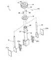
- FIG. 8is a front view of one preferred embodiment of the presently disclosed implant insertion tool
- FIG. 9is a front view of the distal end of the insertion tool shown in FIG. 8;
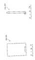
- FIG. 10is a side view of one preferred embodiment of the presently disclosed implant.
- FIG. 11is a side cross-sectional view of the implant shown in FIG. 10 taken along section lines 11 — 11 in FIG. 10
- FIGS. 1 and 1Aillustrate perspective views of the presently disclosed distractor/guide sleeve assembly, which is shown generally as 10 .
- Distractor/guide sleeve assembly 10includes a body 12 , a rotatable dial 14 , a ring 16 , a pair of distractor rods 18 , two pairs of jaws 20 a and 20 b and a pair of cover plates 22 a and 22 b.
- dial 14is rotatable to retract or advance distractor rods 18 to effect opening and closing, i.e., of each pair of jaws 20 a and 20 b.
- distractor body 12includes a tubular portion 24 and a hollow rectangular base portion 26 which are integrally formed. Although not shown, windows or openings may be formed in tubular portion 24 or base portion 26 to provide visibility.
- Tubular portion 24defines a lumen 28 (FIG. 1) having a first open end 28 a and a second end 28 b in communication with hollow base portion 26 .
- a semi-circular rod guide 30is formed on each side of tubular portion 24 .
- Rod guides 30are configured to slidably receive and guide distractor rods 18 .
- First end 28 a of tubular portion 24includes a series of threads 32 for rotatably receiving dial 14 .
- ring 16is circular and includes a pair of stepped bores 34 and an annular channel 36 formed thereabout. Stepped bores 34 are dimensioned to receive screws 38 (FIG. 1A) for securing rods 18 to ring 16 .
- Ring 16is secured within dial 14 (see FIGS. 3 c and 3 d ) with pins 40 (FIG. 1 A). Pins 40 extend through openings 42 in dial 14 into annular channel 36 of ring 16 to secure ring 16 within dial 14 while allowing dial 14 to rotate in relation to ring 16 .
- Dial 14includes a grooved outer surface 15 to facilitate gripping and rotating dial 14 . Dial 14 also includes a threaded bore 17 dimensioned to receive threaded first end 28 a of body 12 .
- each distractor rod 18includes a rod portion 44 and a plate portion 46 .
- Rod portion 44includes a first end having a threaded bore 48 and a second end having a slot 50 formed therein.
- Each threaded bore 48is dimensioned to receive screw 38 (FIG. 1A) to secure the first end of rod portion 44 to ring 16 .
- Each slot 50 of rod portion 44is configured and dimensioned to slidably receive plate portion 46 .
- Plate portion 46is frictionally retained within slot 50 .
- other retaining meansmay be used to secure plate portion 46 within slot 50 , e.g., screws, adhesives, ultrasonic welding, etc.
- Plate portion 46includes a paddle section 52 and a handle section 54 .
- Handle section 54is dimensioned to be received in slot 50 of rod portion 44 .
- Paddle section 52includes a flat base 51 having a plurality of cam members 56 extending therefrom. Cam members 56 will be described in further detail below.
- each jaw 20 of the two pair of jaws 20 a and 20 bincludes a body 60 having a distally extending finger 62 .
- Body 60includes one or more cam slots 64 formed therein.
- body 60includes two cam slots, although three or more may be provided. Alternately, only a single cam slot need be provided.
- Cam slots 64are dimensioned to receive cam members 56 formed on plate portion 46 of distractor rods 18 . Alternately, only a single pair of jaws need be provided on the distractor/guide sleeve. Such an embodiment would also require only a single distractor rod and cover plate.
- cover plates 22 a and 22 bare secured to open sides of base portion 26 to retain jaws 20 and plate portion 46 of distractor rods 18 in engagement.
- Cover plates 22 a and 22 bmay snap fit to base portion 26 or other attachment means may be provided, e.g., screws, welding, adhesives, etc.
- dial 14In operation, when dial 14 is rotated in a clockwise direction on the threaded end of body 12 , dial 14 advances ring 16 towards the second end of body 12 . Movement of ring 16 advances distractor rods 18 in a direction parallel to the longitudinal axis of body 12 , thus advancing cam members 56 in a direction parallel to the longitudinal axis of body 12 . As cam members 56 move in relation to cam slots 64 , each jaw 20 of each pair of jaws 20 a and 20 b is urged outward away from the longitudinal axis of body 12 to increase the spacing between the fingers 62 of each pair of jaws 20 a and 20 b. When dial 14 is rotated in a counter-clockwise direction, rods 18 are retracted to decrease the spacing between each of fingers 62 of each pair of jaws 20 a and 20 b in a manner similar to that described above.
- the above described distractor/guide sleevemay be used to distract adjacent vertebrae during spinal surgery, e.g., a cervical spinal fusion procedure.
- the distractor body including the tubular portion and the base portionfunction as a guide for the surgical instruments used during the surgical procedure, e.g., reamers, taps, insertion tool, etc.
- dial 14can be rotated to distract the adjacent vertebrae. It is no longer necessary to relocate the proper graft bed after each time a surgical instrument is used, since the distractor/guide sleeve is secured in a fixed location with respect to the graft bed during the entire procedure.
- the presently disclosed jaw structureprovides a sturdy structure which minimizes wobbling which may occur while using the surgical instruments.
- FIGS. 8 and 9illustrate an insertion tool, shown generally as 100 , for inserting a thread implant into an implant receiving bed.
- Insertion tool 10includes a handle 110 , an elongated shaft 11 and an implant engaging structure 120 .
- Implant engaging structure 120is secured to or formed integrally with elongated shaft 111 and includes a base member 112 and a pair of protrusions or prongs 114 .
- Base member 112includes a flat face which abuts the trailing end of an implant when the implant is supported on the insertion tool.
- Protrusions 114have an outer surface 116 which is at least partially roughened. The roughened surface may include ridges, knurling, dimples or any other slip resistant surface.
- FIGS. 10 and 11illustrate an implant 200 having a cylindrical threaded body 210 and top and bottom surfaces 212 and 214 .
- Implant 200is constructed from a biocompatible material.
- implant 200is formed from cortical or cancellous bone.
- Top surface 212includes a pair of substantially cylindrical bores 216 formed therein. Bores 216 are positioned to receive protrusions 114 (FIG. 9) and have an inside diameter substantially equal to the outside diameter of protrusions 114 .
- protrusions 114When protrusions 114 are pressed into bores 216 , roughened outer surface 116 of protrusions 114 prevent implant 200 from separating from engaging structure 120 without applying additional force to implant 200 .
- handle 110can be manipulated to thread implant 200 into a previously prepared receiving bed, e.g., a tapped bore formed between adjacent vertebrae during a spinal fusion surgical procedure. Thereafter, insertion tool 100 can be pulled rearwardly with a force sufficient to overcome the frictional engagement between protrusions 114 and bores 26 to separate the implant from the insertion tool.
- a previously prepared receiving bede.g., a tapped bore formed between adjacent vertebrae during a spinal fusion surgical procedure.
- any materials having the requisite strength requirements which are suitable for surgical usemay be used to construct the distractor/guide sleeve assembly and insertion tool including surgical grade stainless steel, plastics, etc.
- the size of the distractor/guide sleevemay be changed to suit a particular surgical procedure, e.g., cervical spinal fusion, lumbar spinal fusion, thoracic spinal fusion, etc. Therefore, the above description should not be construed as limiting, but merely as exemplifications of preferred embodiments. Those skilled in the art will envision other modifications within the scope and spirit of this disclosure.
Landscapes
- Health & Medical Sciences (AREA)
- Biomedical Technology (AREA)
- Engineering & Computer Science (AREA)
- Orthopedic Medicine & Surgery (AREA)
- Life Sciences & Earth Sciences (AREA)
- General Health & Medical Sciences (AREA)
- Veterinary Medicine (AREA)
- Transplantation (AREA)
- Neurology (AREA)
- Animal Behavior & Ethology (AREA)
- Heart & Thoracic Surgery (AREA)
- Public Health (AREA)
- Surgery (AREA)
- Cardiology (AREA)
- Oral & Maxillofacial Surgery (AREA)
- Vascular Medicine (AREA)
- Molecular Biology (AREA)
- Nuclear Medicine, Radiotherapy & Molecular Imaging (AREA)
- Medical Informatics (AREA)
- Physical Education & Sports Medicine (AREA)
- Prostheses (AREA)
Abstract
Description
Claims (11)
Priority Applications (2)
| Application Number | Priority Date | Filing Date | Title |
|---|---|---|---|
| US09/850,494US6569168B2 (en) | 2000-05-05 | 2001-05-07 | Intervertebral distractor and implant insertion instrument |
| US10/335,004US20030130667A1 (en) | 2000-05-05 | 2002-12-30 | Intervertebral distractor and implant insertion instrument |
Applications Claiming Priority (2)
| Application Number | Priority Date | Filing Date | Title |
|---|---|---|---|
| US20222500P | 2000-05-05 | 2000-05-05 | |
| US09/850,494US6569168B2 (en) | 2000-05-05 | 2001-05-07 | Intervertebral distractor and implant insertion instrument |
Related Child Applications (1)
| Application Number | Title | Priority Date | Filing Date |
|---|---|---|---|
| US10/335,004DivisionUS20030130667A1 (en) | 2000-05-05 | 2002-12-30 | Intervertebral distractor and implant insertion instrument |
Publications (2)
| Publication Number | Publication Date |
|---|---|
| US20020010473A1 US20020010473A1 (en) | 2002-01-24 |
| US6569168B2true US6569168B2 (en) | 2003-05-27 |
Family
ID=22748973
Family Applications (2)
| Application Number | Title | Priority Date | Filing Date |
|---|---|---|---|
| US09/850,494Expired - LifetimeUS6569168B2 (en) | 2000-05-05 | 2001-05-07 | Intervertebral distractor and implant insertion instrument |
| US10/335,004AbandonedUS20030130667A1 (en) | 2000-05-05 | 2002-12-30 | Intervertebral distractor and implant insertion instrument |
Family Applications After (1)
| Application Number | Title | Priority Date | Filing Date |
|---|---|---|---|
| US10/335,004AbandonedUS20030130667A1 (en) | 2000-05-05 | 2002-12-30 | Intervertebral distractor and implant insertion instrument |
Country Status (3)
| Country | Link |
|---|---|
| US (2) | US6569168B2 (en) |
| AU (1) | AU2001259593A1 (en) |
| WO (1) | WO2001085033A2 (en) |
Cited By (68)
| Publication number | Priority date | Publication date | Assignee | Title |
|---|---|---|---|---|
| US20030055503A1 (en)* | 2001-09-19 | 2003-03-20 | O'neil Michael J. | Alignment verification device and method of use |
| US20030225416A1 (en)* | 2002-05-21 | 2003-12-04 | Bonvallet Todd C. | Instruments and techniques for separating bony structures |
| US20040162616A1 (en)* | 2002-10-21 | 2004-08-19 | Simonton T. Andrew | Systems and techniques for restoring and maintaining intervertebral anatomy |
| US20040167628A1 (en)* | 2002-10-21 | 2004-08-26 | Foley Kevin T. | Systems and techniques for restoring and maintaining intervertebral anatomy |
| US20040176764A1 (en)* | 2003-03-03 | 2004-09-09 | Centerpulse Spine-Tech, Inc. | Apparatus and method for spinal distraction using a flip-up portal |
| US20050038511A1 (en)* | 2003-08-15 | 2005-02-17 | Martz Erik O. | Transforaminal lumbar interbody fusion (TLIF) implant, surgical procedure and instruments for insertion of spinal implant in a spinal disc space |
| US20050075643A1 (en)* | 2002-10-08 | 2005-04-07 | Schwab Frank J. | Insertion device and techniques for orthopaedic implants |
| US20050203533A1 (en)* | 2004-03-12 | 2005-09-15 | Sdgi Holdings, Inc. | Technique and instrumentation for intervertebral prosthesis implantation |
| US20050283161A1 (en)* | 2004-06-16 | 2005-12-22 | Sdgi Holdings, Inc. | Constant lift cam spreader |
| US20060004376A1 (en)* | 2004-07-02 | 2006-01-05 | Kenneth Shipp | Device for inserting implants |
| US20060100634A1 (en)* | 2004-11-09 | 2006-05-11 | Sdgi Holdings, Inc. | Technique and instrumentation for measuring and preparing a vertebral body for device implantation using datum block |
| US20060106380A1 (en)* | 2003-10-21 | 2006-05-18 | Innovative Spinal Technologies | Extension for use with stabilization systems for internal structures |
| US20060235279A1 (en)* | 2005-03-18 | 2006-10-19 | Hawkes David T | Less invasive access port system and method for using the same |
| US20070010885A1 (en)* | 1997-08-26 | 2007-01-11 | Mingyan Liu | Spinal implant and cutting tool preparation accessory for mounting the implant |
| US20070073293A1 (en)* | 2003-10-16 | 2007-03-29 | Martz Erik O | System and method for flexible correction of bony motion segment |
| US20070093898A1 (en)* | 2005-09-26 | 2007-04-26 | Schwab Frank J | Transforaminal hybrid implant |
| US20070238932A1 (en)* | 2006-03-08 | 2007-10-11 | Jones Robert J | Surgical retractor and retractor assembly |
| US20070276406A1 (en)* | 2004-02-09 | 2007-11-29 | Depuy Spine, Inc | Systems and Methods for Spinal Surgery |
| US20080015417A1 (en)* | 2006-07-11 | 2008-01-17 | Hawkes David T | Selectively locking minimally traumatic access port |
| US20080021555A1 (en)* | 2006-07-19 | 2008-01-24 | John White | Expandable vertebral body implants and methods of use |
| US20080027544A1 (en)* | 2006-07-28 | 2008-01-31 | Warsaw Orthopedic Inc. | Instruments and techniques for engaging spinal implants for insertion into a spinal space |
| US20080071279A1 (en)* | 2006-06-07 | 2008-03-20 | Stryker Spine | Collet-activated distraction wedge inserter |
| US20080234550A1 (en)* | 2005-05-26 | 2008-09-25 | Hawkes David T | Minimally Traumatic Portal |
| US20080262501A1 (en)* | 2007-04-20 | 2008-10-23 | Richard Evan Chen | Multi-function corpectomy instrument |
| US20080275455A1 (en)* | 2006-08-16 | 2008-11-06 | Amicus, Llc | Apparatus and Methods for Inserting an Implant |
| US20090198246A1 (en)* | 2005-04-15 | 2009-08-06 | Roy Lim | Instruments, implants and methods for positioning implants into a spinal disc space |
| US20090228110A1 (en)* | 2008-03-07 | 2009-09-10 | K2M, Inc. | Intervertebral instrument, implant, and method |
| US20090265007A1 (en)* | 2007-11-12 | 2009-10-22 | Dennis Colleran | Vertebral interbody compression implant |
| US7625379B2 (en) | 2004-01-26 | 2009-12-01 | Warsaw Orthopedic, Inc. | Methods and instrumentation for inserting intervertebral grafts and devices |
| US7662185B2 (en) | 1999-12-30 | 2010-02-16 | Osteotech, Inc. | Intervertebral implants |
| US20100114183A1 (en)* | 2008-10-31 | 2010-05-06 | K2M, Inc. | Implant insertion tool |
| US7726002B2 (en) | 2001-12-05 | 2010-06-01 | Osteotech, Inc. | Processes for making spinal intervertebral implant, interconnections for such implant |
| US7780708B2 (en) | 2000-10-20 | 2010-08-24 | Osteotech, Inc. | Implant retaining device |
| US20100262199A1 (en)* | 2007-10-23 | 2010-10-14 | Todd Wallenstein | Implant insertion tool |
| US7833245B2 (en) | 2001-07-12 | 2010-11-16 | Osteotech, Inc. | Intervertebral implant with movement resistant structure |
| US7833255B2 (en) | 2001-12-27 | 2010-11-16 | Osteotech, Inc. | Bone fasteners and method for stabilizing vertebral bone facets using the bone fasteners |
| US7931692B2 (en) | 2001-02-14 | 2011-04-26 | Osteotech, Inc. | Implant derived from bone |
| US7967826B2 (en) | 2003-10-21 | 2011-06-28 | Theken Spine, Llc | Connector transfer tool for internal structure stabilization systems |
| US7988693B2 (en) | 2002-07-19 | 2011-08-02 | Warsaw Orthopedic, Inc. | Chisels and procedure for insertion of spinal implant in a spinal disc space |
| US7988699B2 (en) | 2004-10-19 | 2011-08-02 | Warsaw Orthopedic, Inc. | Adjustable instrumentation for spinal implant insertion |
| US7988733B2 (en) | 2003-06-03 | 2011-08-02 | Warsaw Orthopedic, Inc | Bioimplant with nonuniformly configured protrusions on the load bearing surfaces thereof |
| US8062217B2 (en) | 2007-01-26 | 2011-11-22 | Theken Spine, Llc | Surgical retractor with removable blades and method of use |
| US8100972B1 (en) | 2007-07-02 | 2012-01-24 | Theken Spine, Llc | Spinal cage having deployable member |
| US8114088B2 (en) | 2008-09-19 | 2012-02-14 | Zimmer Spine, Inc. | Geared spinal implant inserter-distractor |
| US8292958B1 (en) | 2007-07-02 | 2012-10-23 | Theken Spine, Llc | Spinal cage having deployable member |
| US8333985B2 (en) | 2004-01-27 | 2012-12-18 | Warsaw Orthopedic, Inc. | Non-glycerol stabilized bone graft |
| US8372157B2 (en) | 2007-02-12 | 2013-02-12 | Warsaw Orthopedic, Inc. | Joint revision implant |
| US8486081B2 (en) | 2007-07-23 | 2013-07-16 | DePuy Synthes Products, LLC | Implant insertion device and method |
| US8540721B2 (en) | 2011-04-04 | 2013-09-24 | Amicus Design Group, Llc | Adjustable apparatus and methods for inserting an implant |
| US8545562B1 (en) | 2007-07-02 | 2013-10-01 | Theken Spine, Llc | Deployable member for use with an intervertebral cage |
| US8864829B1 (en) | 2007-07-02 | 2014-10-21 | Theken Spine, Llc | Spinal cage having deployable member |
| US9358122B2 (en) | 2011-01-07 | 2016-06-07 | K2M, Inc. | Interbody spacer |
| US9867714B1 (en) | 2011-09-23 | 2018-01-16 | Samy Abdou | Spinal fixation devices and methods of use |
| US10111757B2 (en) | 2012-10-22 | 2018-10-30 | Cogent Spine, LLC | Devices and methods for spinal stabilization and instrumentation |
| US10342674B2 (en) | 2007-07-02 | 2019-07-09 | Theken Spine, Llc | Spinal cage having deployable member |
| US10543107B2 (en) | 2009-12-07 | 2020-01-28 | Samy Abdou | Devices and methods for minimally invasive spinal stabilization and instrumentation |
| US10548740B1 (en) | 2016-10-25 | 2020-02-04 | Samy Abdou | Devices and methods for vertebral bone realignment |
| US10695105B2 (en) | 2012-08-28 | 2020-06-30 | Samy Abdou | Spinal fixation devices and methods of use |
| US10857003B1 (en) | 2015-10-14 | 2020-12-08 | Samy Abdou | Devices and methods for vertebral stabilization |
| US10918498B2 (en) | 2004-11-24 | 2021-02-16 | Samy Abdou | Devices and methods for inter-vertebral orthopedic device placement |
| US10973648B1 (en) | 2016-10-25 | 2021-04-13 | Samy Abdou | Devices and methods for vertebral bone realignment |
| US11006982B2 (en) | 2012-02-22 | 2021-05-18 | Samy Abdou | Spinous process fixation devices and methods of use |
| US11179248B2 (en) | 2018-10-02 | 2021-11-23 | Samy Abdou | Devices and methods for spinal implantation |
| US11364057B2 (en) | 2009-03-27 | 2022-06-21 | Spinal Elements, Inc. | Flanged interbody fusion device |
| US11382769B2 (en) | 2018-09-20 | 2022-07-12 | Spinal Elements, Inc. | Spinal implant device |
| US11911284B2 (en) | 2020-11-19 | 2024-02-27 | Spinal Elements, Inc. | Curved expandable interbody devices and deployment tools |
| US12186201B2 (en) | 2007-07-02 | 2025-01-07 | Theken Spine, Llc | Spinal cage having deployable member |
| US12279969B2 (en) | 2020-12-17 | 2025-04-22 | Spinal Elements, Inc. | Spinal implant device |
Families Citing this family (20)
| Publication number | Priority date | Publication date | Assignee | Title |
|---|---|---|---|---|
| US6709438B2 (en)* | 2000-08-10 | 2004-03-23 | Robert A Dixon | Cam action vertebral spreader |
| US8740987B2 (en) | 2001-06-04 | 2014-06-03 | Warsaw Orthopedic, Inc. | Tissue-derived mesh for orthopedic regeneration |
| US8388684B2 (en) | 2002-05-23 | 2013-03-05 | Pioneer Signal Technology, Inc. | Artificial disc device |
| AU2002950443A0 (en)* | 2002-07-26 | 2002-09-12 | Graeme Brazenor Pty Limited | Spinal implant |
| US7497859B2 (en)* | 2002-10-29 | 2009-03-03 | Kyphon Sarl | Tools for implanting an artificial vertebral disk |
| US20040098129A1 (en)* | 2002-11-13 | 2004-05-20 | Jo-Wen Lin | Spinal implant insertion adjustment instrument and implants for use therewith |
| US7326216B2 (en)* | 2003-04-02 | 2008-02-05 | Warsaw Orthopedic, Inc. | Methods and instrumentation for positioning implants in spinal disc space in an anterior lateral approach |
| US20060149284A1 (en)* | 2004-12-15 | 2006-07-06 | Sdgi Holdings, Inc. | Insertion device and method for inserting a member within the body |
| US8377072B2 (en) | 2006-02-06 | 2013-02-19 | Depuy Spine, Inc. | Medical device installation tool |
| US7976550B2 (en)* | 2006-08-10 | 2011-07-12 | Pioneer Surgical Technology | Insertion instrument for artificial discs |
| US8409213B2 (en)* | 2006-08-10 | 2013-04-02 | Pioneer Surgical Technology, Inc. | Insertion instrument for artificial discs |
| US8118872B2 (en) | 2006-08-10 | 2012-02-21 | Pioneer Surgical Technology, Inc. | System and methods for inserting a spinal disc device into an intervertebral space |
| US8414616B2 (en)* | 2006-09-12 | 2013-04-09 | Pioneer Surgical Technology, Inc. | Mounting devices for fixation devices and insertion instruments used therewith |
| US8372084B2 (en)* | 2006-09-22 | 2013-02-12 | Pioneer Surgical Technology, Inc. | System and methods for inserting a spinal disc device into an intervertebral space |
| US20110093014A1 (en)* | 2009-10-19 | 2011-04-21 | Zimmer Spine, Inc. | Rod with Removable End and Inserter Therefor |
| US9289248B2 (en)* | 2009-11-06 | 2016-03-22 | Kevin Seex | Assembly with offset allowing vertebral distraction by axial rotation of a concentric member |
| US9730802B1 (en) | 2014-01-14 | 2017-08-15 | Nuvasive, Inc. | Spinal fusion implant and related methods |
| US10413427B2 (en)* | 2015-03-19 | 2019-09-17 | Warsaw Orthopedic, Inc. | Spinal implant system and method |
| WO2019051260A1 (en) | 2017-09-08 | 2019-03-14 | Pioneer Surgical Technology, Inc. | Intervertebral implants, instruments, and methods |
| USD907771S1 (en) | 2017-10-09 | 2021-01-12 | Pioneer Surgical Technology, Inc. | Intervertebral implant |
Citations (38)
| Publication number | Priority date | Publication date | Assignee | Title |
|---|---|---|---|---|
| US4156424A (en)* | 1978-05-01 | 1979-05-29 | Burgin Kermit H | Locking adjustable speculum |
| US4545374A (en) | 1982-09-03 | 1985-10-08 | Jacobson Robert E | Method and instruments for performing a percutaneous lumbar diskectomy |
| USD291729S (en) | 1985-05-08 | 1987-09-01 | Zimmer, Inc. | Spinal hook distractor or the like |
| US4878915A (en) | 1987-01-22 | 1989-11-07 | Brantigan John W | Surgical prosthetic implant facilitating vertebral interbody fusion |
| US4898161A (en)* | 1986-12-05 | 1990-02-06 | S+G Implants Gmbh | Forceps for pushing apart vertebrae |
| US4997434A (en) | 1983-02-16 | 1991-03-05 | Seedhom Bahaa B | Prosthetic ligaments and instruments for use in the surgical replacement of ligaments |
| US5059194A (en) | 1990-02-12 | 1991-10-22 | Michelson Gary K | Cervical distractor |
| US5122130A (en) | 1988-03-23 | 1992-06-16 | Waldemar Link Gmbh & Co. | Forceps for inserting intervertebral device |
| US5423825A (en) | 1992-06-10 | 1995-06-13 | Levine; Andrew S. | Spinal fusion instruments and methods |
| US5431658A (en) | 1994-02-14 | 1995-07-11 | Moskovich; Ronald | Facilitator for vertebrae grafts and prostheses |
| US5484437A (en) | 1988-06-13 | 1996-01-16 | Michelson; Gary K. | Apparatus and method of inserting spinal implants |
| US5489307A (en) | 1993-02-10 | 1996-02-06 | Spine-Tech, Inc. | Spinal stabilization surgical method |
| USD374283S (en) | 1994-05-19 | 1996-10-01 | Michelson Gary K | Combined distractor and sleeve for inserting spinal implants |
| US5562736A (en) | 1994-10-17 | 1996-10-08 | Raymedica, Inc. | Method for surgical implantation of a prosthetic spinal disc nucleus |
| US5569262A (en) | 1995-05-19 | 1996-10-29 | Carney; William P. | Guide tool for surgical devices |
| USD377093S (en) | 1994-05-27 | 1996-12-31 | Michelson Gary K | Spinal distractor |
| US5658336A (en) | 1994-03-18 | 1997-08-19 | Pisharodi; Madhavan | Rotating, locking, middle-expanded intervertebral disk stabilizer |
| US5697977A (en) | 1994-03-18 | 1997-12-16 | Pisharodi; Madhavan | Method and apparatus for spondylolisthesis reduction |
| US5704937A (en) | 1993-08-27 | 1998-01-06 | Paulette Fairant | Operative equipment for fixing spinal instrumentation |
| US5722977A (en) | 1996-01-24 | 1998-03-03 | Danek Medical, Inc. | Method and means for anterior lumbar exact cut with quadrilateral osteotome and precision guide/spacer |
| US5741253A (en) | 1988-06-13 | 1998-04-21 | Michelson; Gary Karlin | Method for inserting spinal implants |
| US5772661A (en) | 1988-06-13 | 1998-06-30 | Michelson; Gary Karlin | Methods and instrumentation for the surgical correction of human thoracic and lumbar spinal disease from the antero-lateral aspect of the spine |
| US5797917A (en) | 1995-06-07 | 1998-08-25 | Sdgi Holdings, Inc. | Anterior spinal instrumentation and method for implantation and revision |
| US5797909A (en) | 1988-06-13 | 1998-08-25 | Michelson; Gary Karlin | Apparatus for inserting spinal implants |
| USD401335S (en) | 1997-07-28 | 1998-11-17 | Tibor Koros | Combined cervical and lumbar extractor and injector surgical instrument |
| US5836948A (en) | 1997-01-02 | 1998-11-17 | Saint Francis Medical Technologies, Llc | Spine distraction implant and method |
| US5860977A (en) | 1997-01-02 | 1999-01-19 | Saint Francis Medical Technologies, Llc | Spine distraction implant and method |
| US5885299A (en) | 1994-09-15 | 1999-03-23 | Surgical Dynamics, Inc. | Apparatus and method for implant insertion |
| US5899901A (en) | 1991-05-18 | 1999-05-04 | Middleton; Jeffrey Keith | Spinal fixation system |
| US5928139A (en)* | 1998-04-24 | 1999-07-27 | Koros; Tibor B. | Retractor with adjustable length blades and light pipe guides |
| US5989250A (en) | 1996-10-24 | 1999-11-23 | Spinal Concepts, Inc. | Method and apparatus for spinal fixation |
| US6004326A (en) | 1997-09-10 | 1999-12-21 | United States Surgical | Method and instrumentation for implant insertion |
| US6017342A (en) | 1998-08-05 | 2000-01-25 | Beere Precision Medical Instrumnets, Inc. | Compression and distraction instrument |
| US6024696A (en)* | 1998-04-24 | 2000-02-15 | Hoftman; Moshe | Side wall support speculum |
| US6033405A (en) | 1994-09-15 | 2000-03-07 | Surgical Dynamics, Inc. | Apparatus and method for implant insertion |
| US6042582A (en) | 1997-05-20 | 2000-03-28 | Ray; Charles D. | Instrumentation and method for facilitating insertion of spinal implant |
| US6048342A (en) | 1997-01-02 | 2000-04-11 | St. Francis Medical Technologies, Inc. | Spine distraction implant |
| US6478800B1 (en)* | 2000-05-08 | 2002-11-12 | Depuy Acromed, Inc. | Medical installation tool |
Family Cites Families (19)
| Publication number | Priority date | Publication date | Assignee | Title |
|---|---|---|---|---|
| US1356048A (en)* | 1915-03-26 | 1920-10-19 | Dederer Carleton | Surgical forceps |
| US1918889A (en)* | 1932-05-18 | 1933-07-18 | Joseph B Bacon | Artery forceps |
| US2525222A (en)* | 1947-09-16 | 1950-10-10 | Thurman M Holt | Spanner wrench |
| US3486505A (en)* | 1967-05-22 | 1969-12-30 | Gordon M Morrison | Orthopedic surgical instrument |
| EP0077159A1 (en)* | 1981-10-14 | 1983-04-20 | Brian Norman Atkins | Vertebrae spreader |
| US4877020A (en)* | 1984-11-30 | 1989-10-31 | Vich Jose M O | Apparatus for bone graft |
| US4961740B1 (en)* | 1988-10-17 | 1997-01-14 | Surgical Dynamics Inc | V-thread fusion cage and method of fusing a bone joint |
| US5072634A (en)* | 1990-10-10 | 1991-12-17 | Fred Ryder | Device for removing spikes from shoes |
| US5108422A (en)* | 1990-10-22 | 1992-04-28 | United States Surgical Corporation | Skin fastener |
| US5192327A (en)* | 1991-03-22 | 1993-03-09 | Brantigan John W | Surgical prosthetic implant for vertebrae |
| US5213112A (en)* | 1992-01-29 | 1993-05-25 | Pfizer Hospital Products Group, Inc. | Tension meter for orthopedic surgery |
| DE4328690B4 (en)* | 1993-08-26 | 2006-08-17 | SDGI Holdings, Inc., Wilmington | Intervertebral implant for vertebral body blocking and implantation instrument for positioning the intervertebral implant |
| CN1156255C (en)* | 1993-10-01 | 2004-07-07 | 美商-艾克罗米德公司 | Spinal implant |
| US5620458A (en)* | 1994-03-16 | 1997-04-15 | United States Surgical Corporation | Surgical instruments useful for endoscopic spinal procedures |
| US5980522A (en)* | 1994-07-22 | 1999-11-09 | Koros; Tibor | Expandable spinal implants |
| FR2755603B1 (en)* | 1996-11-12 | 1999-02-26 | Jacques Preaut | ASSEMBLY OF ANCILLARS FOR LAYING HIP PROSTHESIS COTYLS, AND READY-TO-FIT COTYL PROSTHETIC ASSEMBLY |
| US6070924A (en)* | 1998-10-20 | 2000-06-06 | Sweetman; Patricia | Electrical plug extraction device |
| US6277149B1 (en)* | 1999-06-08 | 2001-08-21 | Osteotech, Inc. | Ramp-shaped intervertebral implant |
| US6527773B1 (en)* | 1999-10-07 | 2003-03-04 | Osteotech, Inc. | Cervical dowel and insertion tool |
- 2001
- 2001-05-07AUAU2001259593Apatent/AU2001259593A1/ennot_activeAbandoned
- 2001-05-07WOPCT/US2001/014711patent/WO2001085033A2/enunknown
- 2001-05-07USUS09/850,494patent/US6569168B2/ennot_activeExpired - Lifetime
- 2002
- 2002-12-30USUS10/335,004patent/US20030130667A1/ennot_activeAbandoned
Patent Citations (41)
| Publication number | Priority date | Publication date | Assignee | Title |
|---|---|---|---|---|
| US4156424A (en)* | 1978-05-01 | 1979-05-29 | Burgin Kermit H | Locking adjustable speculum |
| US4545374A (en) | 1982-09-03 | 1985-10-08 | Jacobson Robert E | Method and instruments for performing a percutaneous lumbar diskectomy |
| US4997434A (en) | 1983-02-16 | 1991-03-05 | Seedhom Bahaa B | Prosthetic ligaments and instruments for use in the surgical replacement of ligaments |
| USD291729S (en) | 1985-05-08 | 1987-09-01 | Zimmer, Inc. | Spinal hook distractor or the like |
| US4898161A (en)* | 1986-12-05 | 1990-02-06 | S+G Implants Gmbh | Forceps for pushing apart vertebrae |
| US4878915A (en) | 1987-01-22 | 1989-11-07 | Brantigan John W | Surgical prosthetic implant facilitating vertebral interbody fusion |
| US5122130A (en) | 1988-03-23 | 1992-06-16 | Waldemar Link Gmbh & Co. | Forceps for inserting intervertebral device |
| US5505732A (en) | 1988-06-13 | 1996-04-09 | Michelson; Gary K. | Apparatus and method of inserting spinal implants |
| US5484437A (en) | 1988-06-13 | 1996-01-16 | Michelson; Gary K. | Apparatus and method of inserting spinal implants |
| US5797909A (en) | 1988-06-13 | 1998-08-25 | Michelson; Gary Karlin | Apparatus for inserting spinal implants |
| US5772661A (en) | 1988-06-13 | 1998-06-30 | Michelson; Gary Karlin | Methods and instrumentation for the surgical correction of human thoracic and lumbar spinal disease from the antero-lateral aspect of the spine |
| US5741253A (en) | 1988-06-13 | 1998-04-21 | Michelson; Gary Karlin | Method for inserting spinal implants |
| US5059194A (en) | 1990-02-12 | 1991-10-22 | Michelson Gary K | Cervical distractor |
| US5899901A (en) | 1991-05-18 | 1999-05-04 | Middleton; Jeffrey Keith | Spinal fixation system |
| US5423825A (en) | 1992-06-10 | 1995-06-13 | Levine; Andrew S. | Spinal fusion instruments and methods |
| US5489307A (en) | 1993-02-10 | 1996-02-06 | Spine-Tech, Inc. | Spinal stabilization surgical method |
| US5700291A (en) | 1993-02-10 | 1997-12-23 | Spine-Tech, Inc. | Laparoscopic spinal stabilization method |
| US5704937A (en) | 1993-08-27 | 1998-01-06 | Paulette Fairant | Operative equipment for fixing spinal instrumentation |
| US5431658A (en) | 1994-02-14 | 1995-07-11 | Moskovich; Ronald | Facilitator for vertebrae grafts and prostheses |
| US5658336A (en) | 1994-03-18 | 1997-08-19 | Pisharodi; Madhavan | Rotating, locking, middle-expanded intervertebral disk stabilizer |
| US5697977A (en) | 1994-03-18 | 1997-12-16 | Pisharodi; Madhavan | Method and apparatus for spondylolisthesis reduction |
| USD374283S (en) | 1994-05-19 | 1996-10-01 | Michelson Gary K | Combined distractor and sleeve for inserting spinal implants |
| USD377093S (en) | 1994-05-27 | 1996-12-31 | Michelson Gary K | Spinal distractor |
| US5885299A (en) | 1994-09-15 | 1999-03-23 | Surgical Dynamics, Inc. | Apparatus and method for implant insertion |
| US6033405A (en) | 1994-09-15 | 2000-03-07 | Surgical Dynamics, Inc. | Apparatus and method for implant insertion |
| US5562736A (en) | 1994-10-17 | 1996-10-08 | Raymedica, Inc. | Method for surgical implantation of a prosthetic spinal disc nucleus |
| US5569262A (en) | 1995-05-19 | 1996-10-29 | Carney; William P. | Guide tool for surgical devices |
| US5797917A (en) | 1995-06-07 | 1998-08-25 | Sdgi Holdings, Inc. | Anterior spinal instrumentation and method for implantation and revision |
| US5722977A (en) | 1996-01-24 | 1998-03-03 | Danek Medical, Inc. | Method and means for anterior lumbar exact cut with quadrilateral osteotome and precision guide/spacer |
| US5989250A (en) | 1996-10-24 | 1999-11-23 | Spinal Concepts, Inc. | Method and apparatus for spinal fixation |
| US5876404A (en) | 1997-01-02 | 1999-03-02 | St. Francis Medical Technologies, Llc | Spine distraction implant and method |
| US5860977A (en) | 1997-01-02 | 1999-01-19 | Saint Francis Medical Technologies, Llc | Spine distraction implant and method |
| US5836948A (en) | 1997-01-02 | 1998-11-17 | Saint Francis Medical Technologies, Llc | Spine distraction implant and method |
| US6048342A (en) | 1997-01-02 | 2000-04-11 | St. Francis Medical Technologies, Inc. | Spine distraction implant |
| US6042582A (en) | 1997-05-20 | 2000-03-28 | Ray; Charles D. | Instrumentation and method for facilitating insertion of spinal implant |
| USD401335S (en) | 1997-07-28 | 1998-11-17 | Tibor Koros | Combined cervical and lumbar extractor and injector surgical instrument |
| US6004326A (en) | 1997-09-10 | 1999-12-21 | United States Surgical | Method and instrumentation for implant insertion |
| US5928139A (en)* | 1998-04-24 | 1999-07-27 | Koros; Tibor B. | Retractor with adjustable length blades and light pipe guides |
| US6024696A (en)* | 1998-04-24 | 2000-02-15 | Hoftman; Moshe | Side wall support speculum |
| US6017342A (en) | 1998-08-05 | 2000-01-25 | Beere Precision Medical Instrumnets, Inc. | Compression and distraction instrument |
| US6478800B1 (en)* | 2000-05-08 | 2002-11-12 | Depuy Acromed, Inc. | Medical installation tool |
Cited By (144)
| Publication number | Priority date | Publication date | Assignee | Title |
|---|---|---|---|---|
| US8480745B2 (en) | 1997-08-26 | 2013-07-09 | Warsaw Orthopedic, Inc. | Spinal implant and cutting tool preparation accessory for mounting the implant |
| US20070010885A1 (en)* | 1997-08-26 | 2007-01-11 | Mingyan Liu | Spinal implant and cutting tool preparation accessory for mounting the implant |
| US7662185B2 (en) | 1999-12-30 | 2010-02-16 | Osteotech, Inc. | Intervertebral implants |
| US7780708B2 (en) | 2000-10-20 | 2010-08-24 | Osteotech, Inc. | Implant retaining device |
| US8672980B2 (en) | 2000-10-20 | 2014-03-18 | Warsaw Orthopedic, Inc. | Implant retaining device |
| US20110172777A1 (en)* | 2001-02-14 | 2011-07-14 | Warsaw Orthopedic, Inc. | Implant derived from bone |
| US7931692B2 (en) | 2001-02-14 | 2011-04-26 | Osteotech, Inc. | Implant derived from bone |
| US8608803B2 (en) | 2001-02-14 | 2013-12-17 | Warsaw Orthopedic, Inc. | Implant derived from bone |
| US7833245B2 (en) | 2001-07-12 | 2010-11-16 | Osteotech, Inc. | Intervertebral implant with movement resistant structure |
| US8562648B2 (en) | 2001-07-12 | 2013-10-22 | Warsaw Orthopedic, Inc. | Intervertebral implant with movement resistant structure |
| US20030055503A1 (en)* | 2001-09-19 | 2003-03-20 | O'neil Michael J. | Alignment verification device and method of use |
| US7726002B2 (en) | 2001-12-05 | 2010-06-01 | Osteotech, Inc. | Processes for making spinal intervertebral implant, interconnections for such implant |
| US8672985B2 (en) | 2001-12-27 | 2014-03-18 | Warsaw Orthopedic, Inc. | Bone fasteners and method for stabilizing vertebral bone facets using the bone fasteners |
| US7833255B2 (en) | 2001-12-27 | 2010-11-16 | Osteotech, Inc. | Bone fasteners and method for stabilizing vertebral bone facets using the bone fasteners |
| US20110046679A1 (en)* | 2001-12-27 | 2011-02-24 | David Chow | Bone fasteners and method for stabilizing vertebral bone facets using the bone fasteners |
| US7749231B2 (en) | 2002-05-21 | 2010-07-06 | Warsaw Orthopedic, Inc. | Instruments and techniques for separating bony structures |
| US8523874B2 (en) | 2002-05-21 | 2013-09-03 | Warsaw Orthopedic, Inc. | Instruments and techniques for separating bony structures |
| US20030225416A1 (en)* | 2002-05-21 | 2003-12-04 | Bonvallet Todd C. | Instruments and techniques for separating bony structures |
| US7988693B2 (en) | 2002-07-19 | 2011-08-02 | Warsaw Orthopedic, Inc. | Chisels and procedure for insertion of spinal implant in a spinal disc space |
| US7951154B2 (en) | 2002-10-08 | 2011-05-31 | Warsaw Orthopedic, Inc. | Insertion device and techniques for orthopaedic implants |
| US20100222784A1 (en)* | 2002-10-08 | 2010-09-02 | Schwab Frank J | Insertion device and techniques for orthopaedic implants |
| US20050075643A1 (en)* | 2002-10-08 | 2005-04-07 | Schwab Frank J. | Insertion device and techniques for orthopaedic implants |
| US7771432B2 (en) | 2002-10-08 | 2010-08-10 | Warsaw Orthopedic, Inc. | Insertion device and techniques for orthopaedic implants |
| US20070032872A1 (en)* | 2002-10-21 | 2007-02-08 | Warsaw Orthopedic, Inc. (Successor in interest to SDGI Holdings, Inc.) | Systems and techniques for restoring and maintaining intervertebral anatomy |
| US20040167628A1 (en)* | 2002-10-21 | 2004-08-26 | Foley Kevin T. | Systems and techniques for restoring and maintaining intervertebral anatomy |
| US9737415B2 (en) | 2002-10-21 | 2017-08-22 | Warsaw Orthopedic, Inc. | Systems and techniques for restoring and maintaining intervertebral anatomy |
| US8349011B2 (en) | 2002-10-21 | 2013-01-08 | Warsaw Orthopedic, Inc. | Systems and techniques for restoring and maintaining intervertebral anatomy |
| US20040162616A1 (en)* | 2002-10-21 | 2004-08-19 | Simonton T. Andrew | Systems and techniques for restoring and maintaining intervertebral anatomy |
| US20060235522A1 (en)* | 2002-10-21 | 2006-10-19 | Foley Kevin T | System and techniques for restoring and maintaining intervertebral anatomy |
| US9011541B2 (en) | 2002-10-21 | 2015-04-21 | Warsaw Orthopedic, Inc. | Systems and techniques for restoring and maintaining intervertebral anatomy |
| US7063725B2 (en) | 2002-10-21 | 2006-06-20 | Sdgi Holdings, Inc. | Systems and techniques for restoring and maintaining intervertebral anatomy |
| US7476252B2 (en) | 2002-10-21 | 2009-01-13 | Warsaw Orthopedic, Inc. | System and techniques for restoring and maintaining intervertebral anatomy |
| US20060229727A1 (en)* | 2002-10-21 | 2006-10-12 | Foley Kevin T | Systems and techniques for restoring and maintaining intervertebral anatomy |
| US11399955B2 (en) | 2002-10-21 | 2022-08-02 | Warsaw Orthopedic, Inc. | Systems and techniques for restoring and maintaining intervertebral anatomy |
| US10420655B2 (en) | 2002-10-21 | 2019-09-24 | Warsaw Orthopedic, Inc. | Systems and techniques for restoring and maintaining intervertebral anatomy |
| US6991654B2 (en) | 2002-10-21 | 2006-01-31 | Sdgi Holdings, Inc. | Systems and techniques for restoring and maintaining intervertebral anatomy |
| US7125425B2 (en) | 2002-10-21 | 2006-10-24 | Sdgi Holdings, Inc. | Systems and techniques for restoring and maintaining intervertebral anatomy |
| US20040176764A1 (en)* | 2003-03-03 | 2004-09-09 | Centerpulse Spine-Tech, Inc. | Apparatus and method for spinal distraction using a flip-up portal |
| US7988733B2 (en) | 2003-06-03 | 2011-08-02 | Warsaw Orthopedic, Inc | Bioimplant with nonuniformly configured protrusions on the load bearing surfaces thereof |
| US20050038511A1 (en)* | 2003-08-15 | 2005-02-17 | Martz Erik O. | Transforaminal lumbar interbody fusion (TLIF) implant, surgical procedure and instruments for insertion of spinal implant in a spinal disc space |
| US20070073293A1 (en)* | 2003-10-16 | 2007-03-29 | Martz Erik O | System and method for flexible correction of bony motion segment |
| US7905907B2 (en) | 2003-10-21 | 2011-03-15 | Theken Spine, Llc | Internal structure stabilization system for spanning three or more structures |
| US7967826B2 (en) | 2003-10-21 | 2011-06-28 | Theken Spine, Llc | Connector transfer tool for internal structure stabilization systems |
| US20060106380A1 (en)* | 2003-10-21 | 2006-05-18 | Innovative Spinal Technologies | Extension for use with stabilization systems for internal structures |
| US7588575B2 (en)* | 2003-10-21 | 2009-09-15 | Innovative Spinal Technologies | Extension for use with stabilization systems for internal structures |
| US20100069914A1 (en)* | 2004-01-26 | 2010-03-18 | Puno Rolando M | Methods and instrumentation for inserting intervertebral grafts and devices |
| US7625379B2 (en) | 2004-01-26 | 2009-12-01 | Warsaw Orthopedic, Inc. | Methods and instrumentation for inserting intervertebral grafts and devices |
| US8486083B2 (en) | 2004-01-26 | 2013-07-16 | Warsaw Orthopedic, Inc. | Methods and instrumentation for inserting intervertebral grafts and devices |
| US8333985B2 (en) | 2004-01-27 | 2012-12-18 | Warsaw Orthopedic, Inc. | Non-glycerol stabilized bone graft |
| US20070276406A1 (en)* | 2004-02-09 | 2007-11-29 | Depuy Spine, Inc | Systems and Methods for Spinal Surgery |
| US9180024B2 (en) | 2004-02-09 | 2015-11-10 | Medos International Sarl | Systems and methods for spinal surgery |
| US10398425B2 (en) | 2004-02-09 | 2019-09-03 | Medos International Sarl | Systems and methods for spinal surgery |
| US8016829B2 (en) | 2004-02-09 | 2011-09-13 | Depuy Spine, Inc. | Systems and methods for spinal surgery |
| US20050203533A1 (en)* | 2004-03-12 | 2005-09-15 | Sdgi Holdings, Inc. | Technique and instrumentation for intervertebral prosthesis implantation |
| US7549993B2 (en) | 2004-06-16 | 2009-06-23 | Warsaw Orthopedic, Inc. | Constant lift cam spreader |
| US20050283161A1 (en)* | 2004-06-16 | 2005-12-22 | Sdgi Holdings, Inc. | Constant lift cam spreader |
| US20060004376A1 (en)* | 2004-07-02 | 2006-01-05 | Kenneth Shipp | Device for inserting implants |
| US7608080B2 (en) | 2004-07-02 | 2009-10-27 | Warsaw Orthopedic, Inc. | Device for inserting implants |
| US7988699B2 (en) | 2004-10-19 | 2011-08-02 | Warsaw Orthopedic, Inc. | Adjustable instrumentation for spinal implant insertion |
| US20060100634A1 (en)* | 2004-11-09 | 2006-05-11 | Sdgi Holdings, Inc. | Technique and instrumentation for measuring and preparing a vertebral body for device implantation using datum block |
| US11096799B2 (en) | 2004-11-24 | 2021-08-24 | Samy Abdou | Devices and methods for inter-vertebral orthopedic device placement |
| US10918498B2 (en) | 2004-11-24 | 2021-02-16 | Samy Abdou | Devices and methods for inter-vertebral orthopedic device placement |
| US11992423B2 (en) | 2004-11-24 | 2024-05-28 | Samy Abdou | Devices and methods for inter-vertebral orthopedic device placement |
| US20060235279A1 (en)* | 2005-03-18 | 2006-10-19 | Hawkes David T | Less invasive access port system and method for using the same |
| US20090198246A1 (en)* | 2005-04-15 | 2009-08-06 | Roy Lim | Instruments, implants and methods for positioning implants into a spinal disc space |
| US7575580B2 (en) | 2005-04-15 | 2009-08-18 | Warsaw Orthopedic, Inc. | Instruments, implants and methods for positioning implants into a spinal disc space |
| US8540725B2 (en) | 2005-04-15 | 2013-09-24 | Roy Lim | Instruments, implants and methods for positioning implants into a spinal disc space |
| US8231633B2 (en) | 2005-04-15 | 2012-07-31 | Warsaw Orthopedic | Instruments, implants and methods for positioning implants into a spinal disc space |
| US20080234550A1 (en)* | 2005-05-26 | 2008-09-25 | Hawkes David T | Minimally Traumatic Portal |
| US20070093898A1 (en)* | 2005-09-26 | 2007-04-26 | Schwab Frank J | Transforaminal hybrid implant |
| US7998212B2 (en) | 2005-09-26 | 2011-08-16 | Warsaw Orthopedic, Inc. | Transforaminal hybrid implant |
| US8876687B2 (en) | 2006-03-08 | 2014-11-04 | Zimmer Spine, Inc. | Surgical retractor and retractor assembly |
| US20070238932A1 (en)* | 2006-03-08 | 2007-10-11 | Jones Robert J | Surgical retractor and retractor assembly |
| US8303601B2 (en) | 2006-06-07 | 2012-11-06 | Stryker Spine | Collet-activated distraction wedge inserter |
| US20080071279A1 (en)* | 2006-06-07 | 2008-03-20 | Stryker Spine | Collet-activated distraction wedge inserter |
| US20080015417A1 (en)* | 2006-07-11 | 2008-01-17 | Hawkes David T | Selectively locking minimally traumatic access port |
| US20080021555A1 (en)* | 2006-07-19 | 2008-01-24 | John White | Expandable vertebral body implants and methods of use |
| US7862618B2 (en) | 2006-07-19 | 2011-01-04 | Warsaw Orthopedic, Inc. | Expandable vertebral body implants and methods of use |
| US20080027544A1 (en)* | 2006-07-28 | 2008-01-31 | Warsaw Orthopedic Inc. | Instruments and techniques for engaging spinal implants for insertion into a spinal space |
| US20100256767A1 (en)* | 2006-07-28 | 2010-10-07 | Melkent Anthony J | Instruments and techniques for engaging spinal implants for insertion into a spinal space |
| US8382768B2 (en) | 2006-08-16 | 2013-02-26 | K2M, Inc. | Apparatus and methods for inserting an implant |
| US20080275455A1 (en)* | 2006-08-16 | 2008-11-06 | Amicus, Llc | Apparatus and Methods for Inserting an Implant |
| US8801721B2 (en) | 2006-08-16 | 2014-08-12 | K2M, Inc. | Apparatus and methods for inserting an implant |
| US8062303B2 (en) | 2006-08-16 | 2011-11-22 | K2M, Inc. | Apparatus and methods for inserting an implant |
| US8062217B2 (en) | 2007-01-26 | 2011-11-22 | Theken Spine, Llc | Surgical retractor with removable blades and method of use |
| US8372157B2 (en) | 2007-02-12 | 2013-02-12 | Warsaw Orthopedic, Inc. | Joint revision implant |
| US20080262501A1 (en)* | 2007-04-20 | 2008-10-23 | Richard Evan Chen | Multi-function corpectomy instrument |
| US8292958B1 (en) | 2007-07-02 | 2012-10-23 | Theken Spine, Llc | Spinal cage having deployable member |
| US8545562B1 (en) | 2007-07-02 | 2013-10-01 | Theken Spine, Llc | Deployable member for use with an intervertebral cage |
| US8100972B1 (en) | 2007-07-02 | 2012-01-24 | Theken Spine, Llc | Spinal cage having deployable member |
| US8142508B1 (en) | 2007-07-02 | 2012-03-27 | Theken Spine, Llc | Spinal cage having deployable member which is removable |
| US8864829B1 (en) | 2007-07-02 | 2014-10-21 | Theken Spine, Llc | Spinal cage having deployable member |
| US12186201B2 (en) | 2007-07-02 | 2025-01-07 | Theken Spine, Llc | Spinal cage having deployable member |
| US10342674B2 (en) | 2007-07-02 | 2019-07-09 | Theken Spine, Llc | Spinal cage having deployable member |
| US8366774B1 (en) | 2007-07-02 | 2013-02-05 | Theken Spine, Llc | Spinal cage having deployable member |
| US11090169B2 (en) | 2007-07-02 | 2021-08-17 | Theken Spine, Llc | Spinal cage having deployable member |
| US9522069B1 (en) | 2007-07-02 | 2016-12-20 | Theken Spine, Llc | Spinal cage having deployable member |
| US8486081B2 (en) | 2007-07-23 | 2013-07-16 | DePuy Synthes Products, LLC | Implant insertion device and method |
| US20100262199A1 (en)* | 2007-10-23 | 2010-10-14 | Todd Wallenstein | Implant insertion tool |
| US8343164B2 (en) | 2007-10-23 | 2013-01-01 | K2M, Inc. | Implant insertion tool |
| US20090265007A1 (en)* | 2007-11-12 | 2009-10-22 | Dennis Colleran | Vertebral interbody compression implant |
| US8267997B2 (en) | 2007-11-12 | 2012-09-18 | Theken Spine, Llc | Vertebral interbody compression implant |
| US8449554B2 (en) | 2008-03-07 | 2013-05-28 | K2M, Inc. | Intervertebral implant and instrument with removable section |
| US20090228110A1 (en)* | 2008-03-07 | 2009-09-10 | K2M, Inc. | Intervertebral instrument, implant, and method |
| US8882844B2 (en) | 2008-03-07 | 2014-11-11 | K2M, Inc. | Intervertebral instrument, implant, and method |
| US8114088B2 (en) | 2008-09-19 | 2012-02-14 | Zimmer Spine, Inc. | Geared spinal implant inserter-distractor |
| US20100114183A1 (en)* | 2008-10-31 | 2010-05-06 | K2M, Inc. | Implant insertion tool |
| US8382767B2 (en) | 2008-10-31 | 2013-02-26 | K2M, Inc. | Implant insertion tool |
| US11364057B2 (en) | 2009-03-27 | 2022-06-21 | Spinal Elements, Inc. | Flanged interbody fusion device |
| US10610380B2 (en) | 2009-12-07 | 2020-04-07 | Samy Abdou | Devices and methods for minimally invasive spinal stabilization and instrumentation |
| US10945861B2 (en) | 2009-12-07 | 2021-03-16 | Samy Abdou | Devices and methods for minimally invasive spinal stabilization and instrumentation |
| US11918486B2 (en) | 2009-12-07 | 2024-03-05 | Samy Abdou | Devices and methods for minimally invasive spinal stabilization and instrumentation |
| US10857004B2 (en) | 2009-12-07 | 2020-12-08 | Samy Abdou | Devices and methods for minimally invasive spinal stabilization and instrumentation |
| US10543107B2 (en) | 2009-12-07 | 2020-01-28 | Samy Abdou | Devices and methods for minimally invasive spinal stabilization and instrumentation |
| US9358122B2 (en) | 2011-01-07 | 2016-06-07 | K2M, Inc. | Interbody spacer |
| US8876829B2 (en) | 2011-04-04 | 2014-11-04 | Amicus Design Group, Llc | Adjustable apparatus and methods for inserting an implant |
| US8540721B2 (en) | 2011-04-04 | 2013-09-24 | Amicus Design Group, Llc | Adjustable apparatus and methods for inserting an implant |
| US11517449B2 (en) | 2011-09-23 | 2022-12-06 | Samy Abdou | Spinal fixation devices and methods of use |
| US10575961B1 (en) | 2011-09-23 | 2020-03-03 | Samy Abdou | Spinal fixation devices and methods of use |
| US9901458B1 (en) | 2011-09-23 | 2018-02-27 | Samy Abdou | Spinal fixation devices and methods of use |
| US12167973B2 (en) | 2011-09-23 | 2024-12-17 | Samy Abdou | Spinal fixation devices and methods of use |
| US9867714B1 (en) | 2011-09-23 | 2018-01-16 | Samy Abdou | Spinal fixation devices and methods of use |
| US11324608B2 (en) | 2011-09-23 | 2022-05-10 | Samy Abdou | Spinal fixation devices and methods of use |
| US11006982B2 (en) | 2012-02-22 | 2021-05-18 | Samy Abdou | Spinous process fixation devices and methods of use |
| US11839413B2 (en) | 2012-02-22 | 2023-12-12 | Samy Abdou | Spinous process fixation devices and methods of use |
| US11559336B2 (en) | 2012-08-28 | 2023-01-24 | Samy Abdou | Spinal fixation devices and methods of use |
| US10695105B2 (en) | 2012-08-28 | 2020-06-30 | Samy Abdou | Spinal fixation devices and methods of use |
| US11173040B2 (en) | 2012-10-22 | 2021-11-16 | Cogent Spine, LLC | Devices and methods for spinal stabilization and instrumentation |
| US10111757B2 (en) | 2012-10-22 | 2018-10-30 | Cogent Spine, LLC | Devices and methods for spinal stabilization and instrumentation |
| US11918483B2 (en) | 2012-10-22 | 2024-03-05 | Cogent Spine Llc | Devices and methods for spinal stabilization and instrumentation |
| US10857003B1 (en) | 2015-10-14 | 2020-12-08 | Samy Abdou | Devices and methods for vertebral stabilization |
| US11246718B2 (en) | 2015-10-14 | 2022-02-15 | Samy Abdou | Devices and methods for vertebral stabilization |
| US10973648B1 (en) | 2016-10-25 | 2021-04-13 | Samy Abdou | Devices and methods for vertebral bone realignment |
| US11752008B1 (en) | 2016-10-25 | 2023-09-12 | Samy Abdou | Devices and methods for vertebral bone realignment |
| US11259935B1 (en) | 2016-10-25 | 2022-03-01 | Samy Abdou | Devices and methods for vertebral bone realignment |
| US11058548B1 (en) | 2016-10-25 | 2021-07-13 | Samy Abdou | Devices and methods for vertebral bone realignment |
| US10548740B1 (en) | 2016-10-25 | 2020-02-04 | Samy Abdou | Devices and methods for vertebral bone realignment |
| US10744000B1 (en) | 2016-10-25 | 2020-08-18 | Samy Abdou | Devices and methods for vertebral bone realignment |
| US11382769B2 (en) | 2018-09-20 | 2022-07-12 | Spinal Elements, Inc. | Spinal implant device |
| US12318311B2 (en) | 2018-09-20 | 2025-06-03 | Spinal Elements, Inc. | Spinal implant device |
| US11179248B2 (en) | 2018-10-02 | 2021-11-23 | Samy Abdou | Devices and methods for spinal implantation |
| US11911284B2 (en) | 2020-11-19 | 2024-02-27 | Spinal Elements, Inc. | Curved expandable interbody devices and deployment tools |
| US12414858B2 (en) | 2020-11-19 | 2025-09-16 | Spinal Elements, Inc. | Curved expandable interbody devices and deployment tools |
| US12279969B2 (en) | 2020-12-17 | 2025-04-22 | Spinal Elements, Inc. | Spinal implant device |
Also Published As
| Publication number | Publication date |
|---|---|
| WO2001085033A3 (en) | 2002-04-11 |
| WO2001085033A2 (en) | 2001-11-15 |
| US20030130667A1 (en) | 2003-07-10 |
| AU2001259593A1 (en) | 2001-11-20 |
| US20020010473A1 (en) | 2002-01-24 |
Similar Documents
| Publication | Publication Date | Title |
|---|---|---|
| US6569168B2 (en) | Intervertebral distractor and implant insertion instrument | |
| US11812940B2 (en) | Minimally open interbody access retraction device and surgical method | |
| JP6907301B2 (en) | Bone anchor assembly and related equipment | |
| US6733504B2 (en) | Cervical dowel and insertion tool | |
| CA2648204C (en) | Minimally invasive fixation system | |
| AU2007300727B2 (en) | Minimally invasive retractor and methods of use | |
| AU2022218588A1 (en) | Retractor | |
| CA2617545C (en) | Apparatus for treating spinal stenosis | |
| US8382767B2 (en) | Implant insertion tool | |
| US20090093684A1 (en) | Surgical retractor device and method of use | |
| EP3684277A1 (en) | Patient-mounted surgical support | |
| CN110072481A (en) | Bone anchor assemblies and related equipment | |
| KR20060132588A (en) | Tools and tool kits for performing minimal intervention of the spine | |
| JP2004532061A (en) | Percutaneous surgical device and method | |
| WO2005072081A2 (en) | Methods and devices for improving percutaneous access in minimally invasive surgeries | |
| US12201335B2 (en) | All in one plate holder and spring loaded awl |
Legal Events
| Date | Code | Title | Description |
|---|---|---|---|
| AS | Assignment | Owner name:OSTEOTECH, INC., NEW JERSEY Free format text:ASSIGNMENT OF ASSIGNORS INTEREST;ASSIGNOR:LIN, JO-WEN;REEL/FRAME:012152/0268 Effective date:20010831 | |
| STCF | Information on status: patent grant | Free format text:PATENTED CASE | |
| FEPP | Fee payment procedure | Free format text:PAT HOLDER CLAIMS SMALL ENTITY STATUS, ENTITY STATUS SET TO SMALL (ORIGINAL EVENT CODE: LTOS); ENTITY STATUS OF PATENT OWNER: LARGE ENTITY | |
| FPAY | Fee payment | Year of fee payment:4 | |
| FEPP | Fee payment procedure | Free format text:PAYOR NUMBER ASSIGNED (ORIGINAL EVENT CODE: ASPN); ENTITY STATUS OF PATENT OWNER: LARGE ENTITY | |
| FEPP | Fee payment procedure | Free format text:PAT HOLDER NO LONGER CLAIMS SMALL ENTITY STATUS, ENTITY STATUS SET TO UNDISCOUNTED (ORIGINAL EVENT CODE: STOL); ENTITY STATUS OF PATENT OWNER: LARGE ENTITY | |
| REMI | Maintenance fee reminder mailed | ||
| FPAY | Fee payment | Year of fee payment:8 | |
| SULP | Surcharge for late payment | Year of fee payment:7 | |
| AS | Assignment | Owner name:WARSAW ORTHOPEDIC, INC., INDIANA Free format text:ASSIGNMENT OF ASSIGNORS INTEREST;ASSIGNOR:OSTEOTECH, INC.;REEL/FRAME:026196/0585 Effective date:20110415 | |
| FPAY | Fee payment | Year of fee payment:12 |