US6569159B1 - Cell necrosis apparatus - Google Patents
Cell necrosis apparatusDownload PDFInfo
- Publication number
- US6569159B1 US6569159B1US09/513,727US51372700AUS6569159B1US 6569159 B1US6569159 B1US 6569159B1US 51372700 AUS51372700 AUS 51372700AUS 6569159 B1US6569159 B1US 6569159B1
- Authority
- US
- United States
- Prior art keywords
- electrode
- electrodes
- delivery device
- tissue
- tissue site
- Prior art date
- Legal status (The legal status is an assumption and is not a legal conclusion. Google has not performed a legal analysis and makes no representation as to the accuracy of the status listed.)
- Expired - Fee Related
Links
- 230000017074necrotic cell deathEffects0.000titleclaimsabstractdescription4
- 238000012384transportation and deliveryMethods0.000claimsabstractdescription106
- 238000001802infusionMethods0.000claimsabstractdescription44
- 239000012530fluidSubstances0.000claimsdescription21
- 239000002246antineoplastic agentSubstances0.000claimsdescription13
- 229940127089cytotoxic agentDrugs0.000claimsdescription13
- 239000000243solutionSubstances0.000claimsdescription9
- 239000008151electrolyte solutionSubstances0.000claimsdescription6
- 238000005259measurementMethods0.000claimsdescription3
- FAPWRFPIFSIZLT-UHFFFAOYSA-MSodium chlorideChemical compound[Na+].[Cl-]FAPWRFPIFSIZLT-UHFFFAOYSA-M0.000claimsdescription2
- 239000007788liquidSubstances0.000claims3
- 239000007864aqueous solutionSubstances0.000claims1
- 239000000839emulsionSubstances0.000claims1
- 230000001747exhibiting effectEffects0.000claims1
- 230000002977hyperthermial effectEffects0.000claims1
- 210000001519tissueAnatomy0.000description85
- 238000002679ablationMethods0.000description81
- 206010028980NeoplasmDiseases0.000description76
- 238000011282treatmentMethods0.000description52
- 239000012212insulatorSubstances0.000description37
- 238000000034methodMethods0.000description24
- 238000002604ultrasonographyMethods0.000description22
- 206010020843HyperthermiaDiseases0.000description21
- 230000036031hyperthermiaEffects0.000description21
- 230000003902lesionEffects0.000description14
- 238000003384imaging methodMethods0.000description12
- 238000010438heat treatmentMethods0.000description9
- 230000008569processEffects0.000description9
- 239000000463materialSubstances0.000description8
- 238000009413insulationMethods0.000description7
- 210000004185liverAnatomy0.000description7
- 229910052751metalInorganic materials0.000description7
- 239000002184metalSubstances0.000description7
- 238000007674radiofrequency ablationMethods0.000description6
- 238000010586diagramMethods0.000description5
- 210000000056organAnatomy0.000description5
- 230000000717retained effectEffects0.000description5
- 229910001220stainless steelInorganic materials0.000description5
- 239000010935stainless steelSubstances0.000description5
- 210000004027cellAnatomy0.000description4
- 230000006378damageEffects0.000description4
- 239000007772electrode materialSubstances0.000description4
- 238000001356surgical procedureMethods0.000description4
- 238000009529body temperature measurementMethods0.000description3
- 230000008859changeEffects0.000description3
- 238000002512chemotherapyMethods0.000description3
- 238000002591computed tomographyMethods0.000description3
- 230000000694effectsEffects0.000description3
- 239000000499gelSubstances0.000description3
- 229910001000nickel titaniumInorganic materials0.000description3
- 230000005855radiationEffects0.000description3
- RYGMFSIKBFXOCR-UHFFFAOYSA-NCopperChemical compound[Cu]RYGMFSIKBFXOCR-UHFFFAOYSA-N0.000description2
- 238000012369In process controlMethods0.000description2
- 239000004677NylonSubstances0.000description2
- 239000004642PolyimideSubstances0.000description2
- HZEWFHLRYVTOIW-UHFFFAOYSA-N[Ti].[Ni]Chemical compound[Ti].[Ni]HZEWFHLRYVTOIW-UHFFFAOYSA-N0.000description2
- 230000015572biosynthetic processEffects0.000description2
- 230000017531blood circulationEffects0.000description2
- 201000011510cancerDiseases0.000description2
- 230000000973chemotherapeutic effectEffects0.000description2
- 229910052802copperInorganic materials0.000description2
- 239000010949copperSubstances0.000description2
- 238000000151depositionMethods0.000description2
- 238000013461designMethods0.000description2
- 238000010965in-process controlMethods0.000description2
- 230000006698inductionEffects0.000description2
- 230000004807localizationEffects0.000description2
- 238000002595magnetic resonance imagingMethods0.000description2
- 230000007246mechanismEffects0.000description2
- 238000002324minimally invasive surgeryMethods0.000description2
- 238000012544monitoring processMethods0.000description2
- 229920001778nylonPolymers0.000description2
- 230000002093peripheral effectEffects0.000description2
- BASFCYQUMIYNBI-UHFFFAOYSA-NplatinumChemical compound[Pt]BASFCYQUMIYNBI-UHFFFAOYSA-N0.000description2
- 229920001721polyimidePolymers0.000description2
- 102000004169proteins and genesHuman genes0.000description2
- 108090000623proteins and genesProteins0.000description2
- 230000003685thermal hair damageEffects0.000description2
- -121 gaugeSubstances0.000description1
- 229920002134Carboxymethyl cellulosePolymers0.000description1
- 206010027476MetastasesDiseases0.000description1
- BQCADISMDOOEFD-UHFFFAOYSA-NSilverChemical compound[Ag]BQCADISMDOOEFD-UHFFFAOYSA-N0.000description1
- 229910000639Spring steelInorganic materials0.000description1
- 238000010521absorption reactionMethods0.000description1
- 229910052782aluminiumInorganic materials0.000description1
- XAGFODPZIPBFFR-UHFFFAOYSA-NaluminiumChemical compound[Al]XAGFODPZIPBFFR-UHFFFAOYSA-N0.000description1
- 238000005452bendingMethods0.000description1
- 210000000988bone and boneAnatomy0.000description1
- 239000001768carboxy methyl celluloseSubstances0.000description1
- 235000010948carboxy methyl celluloseNutrition0.000description1
- 239000008112carboxymethyl-celluloseSubstances0.000description1
- 210000000170cell membraneAnatomy0.000description1
- 230000001413cellular effectEffects0.000description1
- 238000012512characterization methodMethods0.000description1
- 229920001940conductive polymerPolymers0.000description1
- 239000004020conductorSubstances0.000description1
- 230000001086cytosolic effectEffects0.000description1
- 230000001419dependent effectEffects0.000description1
- 230000008021depositionEffects0.000description1
- 238000011161developmentMethods0.000description1
- 102000038379digestive enzymesHuman genes0.000description1
- 108091007734digestive enzymesProteins0.000description1
- 230000003467diminishing effectEffects0.000description1
- 229940021013electrolyte solutionDrugs0.000description1
- 230000003028elevating effectEffects0.000description1
- 230000008029eradicationEffects0.000description1
- 230000005284excitationEffects0.000description1
- 239000000835fiberSubstances0.000description1
- 238000002594fluoroscopyMethods0.000description1
- 230000006870functionEffects0.000description1
- PCHJSUWPFVWCPO-UHFFFAOYSA-NgoldChemical compound[Au]PCHJSUWPFVWCPO-UHFFFAOYSA-N0.000description1
- 229910052737goldInorganic materials0.000description1
- 239000010931goldSubstances0.000description1
- 230000001900immune effectEffects0.000description1
- 238000002847impedance measurementMethods0.000description1
- 238000012423maintenanceMethods0.000description1
- 230000003211malignant effectEffects0.000description1
- 238000007726management methodMethods0.000description1
- 230000009401metastasisEffects0.000description1
- 238000012986modificationMethods0.000description1
- 230000004048modificationEffects0.000description1
- 210000003205muscleAnatomy0.000description1
- HLXZNVUGXRDIFK-UHFFFAOYSA-Nnickel titaniumChemical compound[Ti].[Ti].[Ti].[Ti].[Ti].[Ti].[Ti].[Ti].[Ti].[Ti].[Ti].[Ni].[Ni].[Ni].[Ni].[Ni].[Ni].[Ni].[Ni].[Ni].[Ni].[Ni].[Ni].[Ni].[Ni]HLXZNVUGXRDIFK-UHFFFAOYSA-N0.000description1
- 210000000633nuclear envelopeAnatomy0.000description1
- 238000010899nucleationMethods0.000description1
- 239000013307optical fiberSubstances0.000description1
- 239000006072pasteSubstances0.000description1
- 230000035699permeabilityEffects0.000description1
- 239000002504physiological saline solutionSubstances0.000description1
- 238000013439planningMethods0.000description1
- 239000004033plasticSubstances0.000description1
- 229920003023plasticPolymers0.000description1
- 229910052697platinumInorganic materials0.000description1
- 229920000728polyesterPolymers0.000description1
- 230000009467reductionEffects0.000description1
- 230000029058respiratory gaseous exchangeEffects0.000description1
- 230000000284resting effectEffects0.000description1
- 229910052709silverInorganic materials0.000description1
- 239000004332silverSubstances0.000description1
- 239000011780sodium chlorideSubstances0.000description1
- 239000007787solidSubstances0.000description1
- 230000002459sustained effectEffects0.000description1
- 230000002195synergetic effectEffects0.000description1
- 238000003786synthesis reactionMethods0.000description1
- 238000002560therapeutic procedureMethods0.000description1
- 229920001169thermoplasticPolymers0.000description1
- 239000004416thermosoftening plasticSubstances0.000description1
- 238000000015thermotherapyMethods0.000description1
- 238000003325tomographyMethods0.000description1
- 238000012546transferMethods0.000description1
- 230000000472traumatic effectEffects0.000description1
- 238000012800visualizationMethods0.000description1
Images


Classifications
- A—HUMAN NECESSITIES
- A61—MEDICAL OR VETERINARY SCIENCE; HYGIENE
- A61B—DIAGNOSIS; SURGERY; IDENTIFICATION
- A61B18/00—Surgical instruments, devices or methods for transferring non-mechanical forms of energy to or from the body
- A61B18/04—Surgical instruments, devices or methods for transferring non-mechanical forms of energy to or from the body by heating
- A61B18/12—Surgical instruments, devices or methods for transferring non-mechanical forms of energy to or from the body by heating by passing a current through the tissue to be heated, e.g. high-frequency current
- A61B18/14—Probes or electrodes therefor
- A61B18/1477—Needle-like probes
- A—HUMAN NECESSITIES
- A61—MEDICAL OR VETERINARY SCIENCE; HYGIENE
- A61B—DIAGNOSIS; SURGERY; IDENTIFICATION
- A61B18/00—Surgical instruments, devices or methods for transferring non-mechanical forms of energy to or from the body
- A61B18/04—Surgical instruments, devices or methods for transferring non-mechanical forms of energy to or from the body by heating
- A61B18/12—Surgical instruments, devices or methods for transferring non-mechanical forms of energy to or from the body by heating by passing a current through the tissue to be heated, e.g. high-frequency current
- A61B18/14—Probes or electrodes therefor
- A61B18/1482—Probes or electrodes therefor having a long rigid shaft for accessing the inner body transcutaneously in minimal invasive surgery, e.g. laparoscopy
- A—HUMAN NECESSITIES
- A61—MEDICAL OR VETERINARY SCIENCE; HYGIENE
- A61B—DIAGNOSIS; SURGERY; IDENTIFICATION
- A61B18/00—Surgical instruments, devices or methods for transferring non-mechanical forms of energy to or from the body
- A61B18/18—Surgical instruments, devices or methods for transferring non-mechanical forms of energy to or from the body by applying electromagnetic radiation, e.g. microwaves
- A61B18/1815—Surgical instruments, devices or methods for transferring non-mechanical forms of energy to or from the body by applying electromagnetic radiation, e.g. microwaves using microwaves
- A—HUMAN NECESSITIES
- A61—MEDICAL OR VETERINARY SCIENCE; HYGIENE
- A61N—ELECTROTHERAPY; MAGNETOTHERAPY; RADIATION THERAPY; ULTRASOUND THERAPY
- A61N1/00—Electrotherapy; Circuits therefor
- A61N1/40—Applying electric fields by inductive or capacitive coupling ; Applying radio-frequency signals
- A61N1/403—Applying electric fields by inductive or capacitive coupling ; Applying radio-frequency signals for thermotherapy, e.g. hyperthermia
- A—HUMAN NECESSITIES
- A61—MEDICAL OR VETERINARY SCIENCE; HYGIENE
- A61N—ELECTROTHERAPY; MAGNETOTHERAPY; RADIATION THERAPY; ULTRASOUND THERAPY
- A61N5/00—Radiation therapy
- A61N5/02—Radiation therapy using microwaves
- A—HUMAN NECESSITIES
- A61—MEDICAL OR VETERINARY SCIENCE; HYGIENE
- A61N—ELECTROTHERAPY; MAGNETOTHERAPY; RADIATION THERAPY; ULTRASOUND THERAPY
- A61N5/00—Radiation therapy
- A61N5/02—Radiation therapy using microwaves
- A61N5/04—Radiators for near-field treatment
- A61N5/045—Radiators for near-field treatment specially adapted for treatment inside the body
- C—CHEMISTRY; METALLURGY
- C22—METALLURGY; FERROUS OR NON-FERROUS ALLOYS; TREATMENT OF ALLOYS OR NON-FERROUS METALS
- C22C—ALLOYS
- C22C1/00—Making non-ferrous alloys
- C22C1/04—Making non-ferrous alloys by powder metallurgy
- C22C1/047—Making non-ferrous alloys by powder metallurgy comprising intermetallic compounds
- C—CHEMISTRY; METALLURGY
- C22—METALLURGY; FERROUS OR NON-FERROUS ALLOYS; TREATMENT OF ALLOYS OR NON-FERROUS METALS
- C22C—ALLOYS
- C22C14/00—Alloys based on titanium
- C—CHEMISTRY; METALLURGY
- C22—METALLURGY; FERROUS OR NON-FERROUS ALLOYS; TREATMENT OF ALLOYS OR NON-FERROUS METALS
- C22F—CHANGING THE PHYSICAL STRUCTURE OF NON-FERROUS METALS AND NON-FERROUS ALLOYS
- C22F1/00—Changing the physical structure of non-ferrous metals or alloys by heat treatment or by hot or cold working
- C22F1/16—Changing the physical structure of non-ferrous metals or alloys by heat treatment or by hot or cold working of other metals or alloys based thereon
- C22F1/18—High-melting or refractory metals or alloys based thereon
- C22F1/183—High-melting or refractory metals or alloys based thereon of titanium or alloys based thereon
- A—HUMAN NECESSITIES
- A61—MEDICAL OR VETERINARY SCIENCE; HYGIENE
- A61B—DIAGNOSIS; SURGERY; IDENTIFICATION
- A61B18/00—Surgical instruments, devices or methods for transferring non-mechanical forms of energy to or from the body
- A61B18/04—Surgical instruments, devices or methods for transferring non-mechanical forms of energy to or from the body by heating
- A61B18/12—Surgical instruments, devices or methods for transferring non-mechanical forms of energy to or from the body by heating by passing a current through the tissue to be heated, e.g. high-frequency current
- A61B18/1206—Generators therefor
- A—HUMAN NECESSITIES
- A61—MEDICAL OR VETERINARY SCIENCE; HYGIENE
- A61B—DIAGNOSIS; SURGERY; IDENTIFICATION
- A61B18/00—Surgical instruments, devices or methods for transferring non-mechanical forms of energy to or from the body
- A61B18/04—Surgical instruments, devices or methods for transferring non-mechanical forms of energy to or from the body by heating
- A61B18/12—Surgical instruments, devices or methods for transferring non-mechanical forms of energy to or from the body by heating by passing a current through the tissue to be heated, e.g. high-frequency current
- A61B18/14—Probes or electrodes therefor
- A61B18/1402—Probes for open surgery
- A—HUMAN NECESSITIES
- A61—MEDICAL OR VETERINARY SCIENCE; HYGIENE
- A61B—DIAGNOSIS; SURGERY; IDENTIFICATION
- A61B18/00—Surgical instruments, devices or methods for transferring non-mechanical forms of energy to or from the body
- A61B18/04—Surgical instruments, devices or methods for transferring non-mechanical forms of energy to or from the body by heating
- A61B18/12—Surgical instruments, devices or methods for transferring non-mechanical forms of energy to or from the body by heating by passing a current through the tissue to be heated, e.g. high-frequency current
- A61B18/14—Probes or electrodes therefor
- A61B18/1485—Probes or electrodes therefor having a short rigid shaft for accessing the inner body through natural openings
- A—HUMAN NECESSITIES
- A61—MEDICAL OR VETERINARY SCIENCE; HYGIENE
- A61B—DIAGNOSIS; SURGERY; IDENTIFICATION
- A61B18/00—Surgical instruments, devices or methods for transferring non-mechanical forms of energy to or from the body
- A61B18/04—Surgical instruments, devices or methods for transferring non-mechanical forms of energy to or from the body by heating
- A61B18/12—Surgical instruments, devices or methods for transferring non-mechanical forms of energy to or from the body by heating by passing a current through the tissue to be heated, e.g. high-frequency current
- A61B18/14—Probes or electrodes therefor
- A61B18/1492—Probes or electrodes therefor having a flexible, catheter-like structure, e.g. for heart ablation
- A—HUMAN NECESSITIES
- A61—MEDICAL OR VETERINARY SCIENCE; HYGIENE
- A61B—DIAGNOSIS; SURGERY; IDENTIFICATION
- A61B17/00—Surgical instruments, devices or methods
- A61B2017/00017—Electrical control of surgical instruments
- A61B2017/00022—Sensing or detecting at the treatment site
- A61B2017/00026—Conductivity or impedance, e.g. of tissue
- A—HUMAN NECESSITIES
- A61—MEDICAL OR VETERINARY SCIENCE; HYGIENE
- A61B—DIAGNOSIS; SURGERY; IDENTIFICATION
- A61B17/00—Surgical instruments, devices or methods
- A61B2017/00017—Electrical control of surgical instruments
- A61B2017/00022—Sensing or detecting at the treatment site
- A61B2017/00084—Temperature
- A61B2017/00101—Temperature using an array of thermosensors
- A—HUMAN NECESSITIES
- A61—MEDICAL OR VETERINARY SCIENCE; HYGIENE
- A61B—DIAGNOSIS; SURGERY; IDENTIFICATION
- A61B18/00—Surgical instruments, devices or methods for transferring non-mechanical forms of energy to or from the body
- A61B2018/00005—Cooling or heating of the probe or tissue immediately surrounding the probe
- A61B2018/00011—Cooling or heating of the probe or tissue immediately surrounding the probe with fluids
- A61B2018/00023—Cooling or heating of the probe or tissue immediately surrounding the probe with fluids closed, i.e. without wound contact by the fluid
- A—HUMAN NECESSITIES
- A61—MEDICAL OR VETERINARY SCIENCE; HYGIENE
- A61B—DIAGNOSIS; SURGERY; IDENTIFICATION
- A61B18/00—Surgical instruments, devices or methods for transferring non-mechanical forms of energy to or from the body
- A61B2018/00053—Mechanical features of the instrument of device
- A61B2018/00184—Moving parts
- A61B2018/00196—Moving parts reciprocating lengthwise
- A—HUMAN NECESSITIES
- A61—MEDICAL OR VETERINARY SCIENCE; HYGIENE
- A61B—DIAGNOSIS; SURGERY; IDENTIFICATION
- A61B18/00—Surgical instruments, devices or methods for transferring non-mechanical forms of energy to or from the body
- A61B2018/00053—Mechanical features of the instrument of device
- A61B2018/00273—Anchoring means for temporary attachment of a device to tissue
- A—HUMAN NECESSITIES
- A61—MEDICAL OR VETERINARY SCIENCE; HYGIENE
- A61B—DIAGNOSIS; SURGERY; IDENTIFICATION
- A61B18/00—Surgical instruments, devices or methods for transferring non-mechanical forms of energy to or from the body
- A61B2018/00315—Surgical instruments, devices or methods for transferring non-mechanical forms of energy to or from the body for treatment of particular body parts
- A61B2018/00452—Skin
- A61B2018/00476—Hair follicles
- A—HUMAN NECESSITIES
- A61—MEDICAL OR VETERINARY SCIENCE; HYGIENE
- A61B—DIAGNOSIS; SURGERY; IDENTIFICATION
- A61B18/00—Surgical instruments, devices or methods for transferring non-mechanical forms of energy to or from the body
- A61B2018/00571—Surgical instruments, devices or methods for transferring non-mechanical forms of energy to or from the body for achieving a particular surgical effect
- A61B2018/00577—Ablation
- A—HUMAN NECESSITIES
- A61—MEDICAL OR VETERINARY SCIENCE; HYGIENE
- A61B—DIAGNOSIS; SURGERY; IDENTIFICATION
- A61B18/00—Surgical instruments, devices or methods for transferring non-mechanical forms of energy to or from the body
- A61B2018/00636—Sensing and controlling the application of energy
- A61B2018/00642—Sensing and controlling the application of energy with feedback, i.e. closed loop control
- A—HUMAN NECESSITIES
- A61—MEDICAL OR VETERINARY SCIENCE; HYGIENE
- A61B—DIAGNOSIS; SURGERY; IDENTIFICATION
- A61B18/00—Surgical instruments, devices or methods for transferring non-mechanical forms of energy to or from the body
- A61B2018/00636—Sensing and controlling the application of energy
- A61B2018/00666—Sensing and controlling the application of energy using a threshold value
- A61B2018/00678—Sensing and controlling the application of energy using a threshold value upper
- A—HUMAN NECESSITIES
- A61—MEDICAL OR VETERINARY SCIENCE; HYGIENE
- A61B—DIAGNOSIS; SURGERY; IDENTIFICATION
- A61B18/00—Surgical instruments, devices or methods for transferring non-mechanical forms of energy to or from the body
- A61B2018/00636—Sensing and controlling the application of energy
- A61B2018/00696—Controlled or regulated parameters
- A61B2018/00702—Power or energy
- A61B2018/00708—Power or energy switching the power on or off
- A—HUMAN NECESSITIES
- A61—MEDICAL OR VETERINARY SCIENCE; HYGIENE
- A61B—DIAGNOSIS; SURGERY; IDENTIFICATION
- A61B18/00—Surgical instruments, devices or methods for transferring non-mechanical forms of energy to or from the body
- A61B2018/00636—Sensing and controlling the application of energy
- A61B2018/00696—Controlled or regulated parameters
- A61B2018/00726—Duty cycle
- A—HUMAN NECESSITIES
- A61—MEDICAL OR VETERINARY SCIENCE; HYGIENE
- A61B—DIAGNOSIS; SURGERY; IDENTIFICATION
- A61B18/00—Surgical instruments, devices or methods for transferring non-mechanical forms of energy to or from the body
- A61B2018/00636—Sensing and controlling the application of energy
- A61B2018/00696—Controlled or regulated parameters
- A61B2018/00744—Fluid flow
- A—HUMAN NECESSITIES
- A61—MEDICAL OR VETERINARY SCIENCE; HYGIENE
- A61B—DIAGNOSIS; SURGERY; IDENTIFICATION
- A61B18/00—Surgical instruments, devices or methods for transferring non-mechanical forms of energy to or from the body
- A61B2018/00636—Sensing and controlling the application of energy
- A61B2018/00696—Controlled or regulated parameters
- A61B2018/00761—Duration
- A—HUMAN NECESSITIES
- A61—MEDICAL OR VETERINARY SCIENCE; HYGIENE
- A61B—DIAGNOSIS; SURGERY; IDENTIFICATION
- A61B18/00—Surgical instruments, devices or methods for transferring non-mechanical forms of energy to or from the body
- A61B2018/00636—Sensing and controlling the application of energy
- A61B2018/00773—Sensed parameters
- A61B2018/00779—Power or energy
- A—HUMAN NECESSITIES
- A61—MEDICAL OR VETERINARY SCIENCE; HYGIENE
- A61B—DIAGNOSIS; SURGERY; IDENTIFICATION
- A61B18/00—Surgical instruments, devices or methods for transferring non-mechanical forms of energy to or from the body
- A61B2018/00636—Sensing and controlling the application of energy
- A61B2018/00773—Sensed parameters
- A61B2018/00791—Temperature
- A61B2018/00797—Temperature measured by multiple temperature sensors
- A—HUMAN NECESSITIES
- A61—MEDICAL OR VETERINARY SCIENCE; HYGIENE
- A61B—DIAGNOSIS; SURGERY; IDENTIFICATION
- A61B18/00—Surgical instruments, devices or methods for transferring non-mechanical forms of energy to or from the body
- A61B2018/00636—Sensing and controlling the application of energy
- A61B2018/00773—Sensed parameters
- A61B2018/00791—Temperature
- A61B2018/00821—Temperature measured by a thermocouple
- A—HUMAN NECESSITIES
- A61—MEDICAL OR VETERINARY SCIENCE; HYGIENE
- A61B—DIAGNOSIS; SURGERY; IDENTIFICATION
- A61B18/00—Surgical instruments, devices or methods for transferring non-mechanical forms of energy to or from the body
- A61B2018/00636—Sensing and controlling the application of energy
- A61B2018/00773—Sensed parameters
- A61B2018/00827—Current
- A—HUMAN NECESSITIES
- A61—MEDICAL OR VETERINARY SCIENCE; HYGIENE
- A61B—DIAGNOSIS; SURGERY; IDENTIFICATION
- A61B18/00—Surgical instruments, devices or methods for transferring non-mechanical forms of energy to or from the body
- A61B2018/00636—Sensing and controlling the application of energy
- A61B2018/00773—Sensed parameters
- A61B2018/00875—Resistance or impedance
- A—HUMAN NECESSITIES
- A61—MEDICAL OR VETERINARY SCIENCE; HYGIENE
- A61B—DIAGNOSIS; SURGERY; IDENTIFICATION
- A61B18/00—Surgical instruments, devices or methods for transferring non-mechanical forms of energy to or from the body
- A61B2018/00636—Sensing and controlling the application of energy
- A61B2018/00773—Sensed parameters
- A61B2018/00892—Voltage
- A—HUMAN NECESSITIES
- A61—MEDICAL OR VETERINARY SCIENCE; HYGIENE
- A61B—DIAGNOSIS; SURGERY; IDENTIFICATION
- A61B18/00—Surgical instruments, devices or methods for transferring non-mechanical forms of energy to or from the body
- A61B18/04—Surgical instruments, devices or methods for transferring non-mechanical forms of energy to or from the body by heating
- A61B18/12—Surgical instruments, devices or methods for transferring non-mechanical forms of energy to or from the body by heating by passing a current through the tissue to be heated, e.g. high-frequency current
- A61B18/1206—Generators therefor
- A61B2018/124—Generators therefor switching the output to different electrodes, e.g. sequentially
- A—HUMAN NECESSITIES
- A61—MEDICAL OR VETERINARY SCIENCE; HYGIENE
- A61B—DIAGNOSIS; SURGERY; IDENTIFICATION
- A61B18/00—Surgical instruments, devices or methods for transferring non-mechanical forms of energy to or from the body
- A61B18/04—Surgical instruments, devices or methods for transferring non-mechanical forms of energy to or from the body by heating
- A61B18/12—Surgical instruments, devices or methods for transferring non-mechanical forms of energy to or from the body by heating by passing a current through the tissue to be heated, e.g. high-frequency current
- A61B18/1206—Generators therefor
- A61B2018/1246—Generators therefor characterised by the output polarity
- A61B2018/1253—Generators therefor characterised by the output polarity monopolar
- A—HUMAN NECESSITIES
- A61—MEDICAL OR VETERINARY SCIENCE; HYGIENE
- A61B—DIAGNOSIS; SURGERY; IDENTIFICATION
- A61B18/00—Surgical instruments, devices or methods for transferring non-mechanical forms of energy to or from the body
- A61B18/04—Surgical instruments, devices or methods for transferring non-mechanical forms of energy to or from the body by heating
- A61B18/12—Surgical instruments, devices or methods for transferring non-mechanical forms of energy to or from the body by heating by passing a current through the tissue to be heated, e.g. high-frequency current
- A61B18/1206—Generators therefor
- A61B2018/1246—Generators therefor characterised by the output polarity
- A61B2018/126—Generators therefor characterised by the output polarity bipolar
- A—HUMAN NECESSITIES
- A61—MEDICAL OR VETERINARY SCIENCE; HYGIENE
- A61B—DIAGNOSIS; SURGERY; IDENTIFICATION
- A61B18/00—Surgical instruments, devices or methods for transferring non-mechanical forms of energy to or from the body
- A61B18/04—Surgical instruments, devices or methods for transferring non-mechanical forms of energy to or from the body by heating
- A61B18/12—Surgical instruments, devices or methods for transferring non-mechanical forms of energy to or from the body by heating by passing a current through the tissue to be heated, e.g. high-frequency current
- A61B18/14—Probes or electrodes therefor
- A61B2018/1405—Electrodes having a specific shape
- A61B2018/1425—Needle
- A61B2018/143—Needle multiple needles
- A—HUMAN NECESSITIES
- A61—MEDICAL OR VETERINARY SCIENCE; HYGIENE
- A61B—DIAGNOSIS; SURGERY; IDENTIFICATION
- A61B18/00—Surgical instruments, devices or methods for transferring non-mechanical forms of energy to or from the body
- A61B18/04—Surgical instruments, devices or methods for transferring non-mechanical forms of energy to or from the body by heating
- A61B18/12—Surgical instruments, devices or methods for transferring non-mechanical forms of energy to or from the body by heating by passing a current through the tissue to be heated, e.g. high-frequency current
- A61B18/14—Probes or electrodes therefor
- A61B2018/1405—Electrodes having a specific shape
- A61B2018/1425—Needle
- A61B2018/1432—Needle curved
- A—HUMAN NECESSITIES
- A61—MEDICAL OR VETERINARY SCIENCE; HYGIENE
- A61B—DIAGNOSIS; SURGERY; IDENTIFICATION
- A61B18/00—Surgical instruments, devices or methods for transferring non-mechanical forms of energy to or from the body
- A61B18/04—Surgical instruments, devices or methods for transferring non-mechanical forms of energy to or from the body by heating
- A61B18/12—Surgical instruments, devices or methods for transferring non-mechanical forms of energy to or from the body by heating by passing a current through the tissue to be heated, e.g. high-frequency current
- A61B18/14—Probes or electrodes therefor
- A61B2018/1405—Electrodes having a specific shape
- A61B2018/1435—Spiral
- A—HUMAN NECESSITIES
- A61—MEDICAL OR VETERINARY SCIENCE; HYGIENE
- A61B—DIAGNOSIS; SURGERY; IDENTIFICATION
- A61B18/00—Surgical instruments, devices or methods for transferring non-mechanical forms of energy to or from the body
- A61B18/04—Surgical instruments, devices or methods for transferring non-mechanical forms of energy to or from the body by heating
- A61B18/12—Surgical instruments, devices or methods for transferring non-mechanical forms of energy to or from the body by heating by passing a current through the tissue to be heated, e.g. high-frequency current
- A61B18/14—Probes or electrodes therefor
- A61B2018/1472—Probes or electrodes therefor for use with liquid electrolyte, e.g. virtual electrodes
- A—HUMAN NECESSITIES
- A61—MEDICAL OR VETERINARY SCIENCE; HYGIENE
- A61B—DIAGNOSIS; SURGERY; IDENTIFICATION
- A61B18/00—Surgical instruments, devices or methods for transferring non-mechanical forms of energy to or from the body
- A61B18/04—Surgical instruments, devices or methods for transferring non-mechanical forms of energy to or from the body by heating
- A61B18/12—Surgical instruments, devices or methods for transferring non-mechanical forms of energy to or from the body by heating by passing a current through the tissue to be heated, e.g. high-frequency current
- A61B18/14—Probes or electrodes therefor
- A61B18/16—Indifferent or passive electrodes for grounding
- A61B2018/162—Indifferent or passive electrodes for grounding located on the probe body
- A—HUMAN NECESSITIES
- A61—MEDICAL OR VETERINARY SCIENCE; HYGIENE
- A61B—DIAGNOSIS; SURGERY; IDENTIFICATION
- A61B18/00—Surgical instruments, devices or methods for transferring non-mechanical forms of energy to or from the body
- A61B18/18—Surgical instruments, devices or methods for transferring non-mechanical forms of energy to or from the body by applying electromagnetic radiation, e.g. microwaves
- A61B18/1815—Surgical instruments, devices or methods for transferring non-mechanical forms of energy to or from the body by applying electromagnetic radiation, e.g. microwaves using microwaves
- A61B2018/1861—Surgical instruments, devices or methods for transferring non-mechanical forms of energy to or from the body by applying electromagnetic radiation, e.g. microwaves using microwaves with an instrument inserted into a body lumen or cavity, e.g. a catheter
- A—HUMAN NECESSITIES
- A61—MEDICAL OR VETERINARY SCIENCE; HYGIENE
- A61B—DIAGNOSIS; SURGERY; IDENTIFICATION
- A61B2218/00—Details of surgical instruments, devices or methods for transferring non-mechanical forms of energy to or from the body
- A61B2218/001—Details of surgical instruments, devices or methods for transferring non-mechanical forms of energy to or from the body having means for irrigation and/or aspiration of substances to and/or from the surgical site
- A61B2218/002—Irrigation
- A—HUMAN NECESSITIES
- A61—MEDICAL OR VETERINARY SCIENCE; HYGIENE
- A61M—DEVICES FOR INTRODUCING MEDIA INTO, OR ONTO, THE BODY; DEVICES FOR TRANSDUCING BODY MEDIA OR FOR TAKING MEDIA FROM THE BODY; DEVICES FOR PRODUCING OR ENDING SLEEP OR STUPOR
- A61M25/00—Catheters; Hollow probes
- A61M25/0067—Catheters; Hollow probes characterised by the distal end, e.g. tips
- A61M25/0068—Static characteristics of the catheter tip, e.g. shape, atraumatic tip, curved tip or tip structure
- A61M25/007—Side holes, e.g. their profiles or arrangements; Provisions to keep side holes unblocked
- A—HUMAN NECESSITIES
- A61—MEDICAL OR VETERINARY SCIENCE; HYGIENE
- A61N—ELECTROTHERAPY; MAGNETOTHERAPY; RADIATION THERAPY; ULTRASOUND THERAPY
- A61N5/00—Radiation therapy
- A61N5/02—Radiation therapy using microwaves
- A61N5/04—Radiators for near-field treatment
- B—PERFORMING OPERATIONS; TRANSPORTING
- B22—CASTING; POWDER METALLURGY
- B22F—WORKING METALLIC POWDER; MANUFACTURE OF ARTICLES FROM METALLIC POWDER; MAKING METALLIC POWDER; APPARATUS OR DEVICES SPECIALLY ADAPTED FOR METALLIC POWDER
- B22F2999/00—Aspects linked to processes or compositions used in powder metallurgy
Definitions
- This inventionrelates generally to an apparatus for the treatment and ablation of body masses, such as tumors, and more particularly, to an RF treatment system suitable for multi-modality treatment with an infusion delivery and a retractable multiple needle electrode apparatus that surrounds an exterior of a tumor with a plurality of needle electrodes and defines an ablative volume.
- the systemmaintains a selected power at an electrode that is independent of changes in current or voltage.
- hyperthermiaAs a tool for treatment of tumors. It is known that elevating the temperature of tumors is helpful in the treatment and management of cancerous tissues. The mechanisms of selective cancer cell eradication by hyperthermia are not completely understood. However, four cellular effects of hyperthermia on cancerous tissue have been proposed, (i) changes in cell or nuclear membrane permeability or fluidity, (ii) cytoplasmic lysomal disintegration, causing release of digestive enzymes, (iii) protein thermal damage affecting cell respiration and the synthesis of DNA or RNA and (iv) potential excitation of immunologic systems. Treatment methods for applying heat to tumors include the use of direct contact radio-frequency (RF) applicators, microwave radiation, inductively coupled RF fields, ultrasound, and a variety of simple thermal conduction techniques.
- RFradio-frequency
- Hyperthermiawhich can be produced from an RF or microwave source, applies heat to tissue but does not exceed 45 degrees C. so that normal cells survive. In thermotherapy, heat energy of greater than 45 degrees C. is applied, resulting in histological damage, desiccation and the denaturization of proteins. Hyperthermia has been applied more recently for therapy of malignant tumors. In hyperthermia, it is desirable to induce a state of hyperthermia that is localized by interstitial current heating to a specific area while concurrently insuring minimum thermal damage to healthy surrounding tissue. Often, the tumor is located subcutaneously and addressing the tumor requires either surgery, endoscopic procedures or external radiation. It is difficult to externally induce hyperthermia in deep body tissue because current density is diluted due to its absorption by healthy tissue. Additionally, a portion of the RF energy is reflected at the muscle/fat and bone interfaces which adds to the problem of depositing a known quantity of energy directly on a small tumor.
- a minimally invasive procedureutilizes two catheters that are inserted interstitially into the tumor.
- the cathetersare placed within the tumor volume and each is connect to a high frequency power source.
- Electrodesmust be properly positioned relative to the tumor. After the electrodes are positioned, it is then desirable to have controlled application and deposition of RF energy to ablate the tumor. This reduces destruction of healthy tissue.
- RF tumor treatment apparatusthat is useful for minimally invasive procedures. It would be desirable for such a device to surround the exterior of the tumor with treatment electrodes, defining a controlled ablation volume, and subsequently the electrodes deliver a controlled amount of RF energy.
- EMelectromagnetic
- a cell necrosis apparatuscomprises an elongated delivery device including a lumen and an energy delivery device.
- the energy delivery deviceincludes at least a first and a second RF electrode each with a tissue piercing distal portion.
- the first and second RF electrodesare positionable in the elongated delivery device in a compacted state and deployable from the elongated delivery device with curvature in a deployed state.
- the first and second RF electrodesexhibit a changing direction of travel when advanced from the elongated delivery device to a selected tissue site.
- At least one infusion portis coupled to one of the elongated delivery device, the energy delivery device, the first RF electrode or the second RF electrode.
- the apparatusmay be configured such that the first and second RF electrodes have independent fluid delivery.
- a tissue ablation apparatusin another embodiment, includes a delivery catheter, with distal and proximal ends.
- a handleis attached to the proximal end of the delivery catheter.
- An electrode deployment apparatusis positioned at least partially in the delivery catheter. It includes a plurality of electrodes that are retractable in and out of the catheter's distal end. The electrodes are in a non-deployed state when they are positioned within the delivery catheter. As they are advanced out the distal end of the catheter they become deployed, and define an ablation volume.
- Each electrodehas a first section with a first radius of curvature, and a second section, extending beyond the first section, having a second radius of curvature or a substantially linear geometry.
- each deployed electrodehas at least two radii of curvature that are formed when the needle is advanced through the delivery catheter's distal end and becomes positioned at a selected tissue site.
- each deployed electrodecan have at least one radius of curvature in two or more planes.
- the electrode deployment apparatuscan include at least one deployed electrode having at least radii of curvature, and at least one deployed electrode with at least one radius of curvature in two or more planes.
- the electrode deployment apparatushas at least one deployed electrode with at least one curved section that is located near the distal end of the delivery catheter, and a non-curved section which extends beyond the curved section of the deployed electrode.
- the electrode deployment apparatusalso has at least one deployed electrode with at least two radii of curvature.
- each deployed electrodehas at least one curved section located near the distal end of the delivery catheter, and a non-curved section that extends beyond the curved section of the deployed electrode.
- An electrode templatecan be positioned at the distal end of the delivery catheter. It assists in guiding the deployment of the electrodes to a surrounding relationship at an exterior of a selected mass in a tissue.
- the electrodescan be hollow.
- An adjustable electrode insulatorcan be positioned in an adjacent, surrounding relationship to all or some of the electrodes. The electrode insulator is adjustable, and capable of being advanced and retracted along the electrodes in order to define an electrode conductive surface.
- the electrode deployment apparatuscan include a cam which advances and retracts the electrodes in and out of the delivery catheter's distal end.
- a camwhich advances and retracts the electrodes in and out of the delivery catheter's distal end.
- one or more guide tubesassociated with one or more electrodes.
- the guide tubesare positioned at the delivery catheter's distal end.
- Sources of infusing mediumscan be associated with the hollow electrodes. Electrodes can have sharpened, tapered ends in order to assist their introduction through tissue, and advancement to the selected tissue site.
- the electrode deployment apparatusis removable from the delivery catheter.
- An obturatoris initially positioned within the delivery catheter. It can have a sharpened distal end.
- the delivery cathetercan be advanced percutaneously to an internal body organ, or site, with the obturator positioned in the delivery catheter. Once positioned, the obturator is removed, and the electrode deployment apparatus is inserted into the delivery catheter.
- the electrodesare in non-deployed states, and preferably compacted or spring-loaded, while positioned within the delivery catheter. They are made of a material with sufficient strength so that as the electrodes emerge from the delivery catheter's distal end they are deployed three dimensionally, in a lateral direction away from the periphery of the delivery catheter's distal end. The electrodes continue their lateral movement until the force applied by the tissue causes the needles to change their direction of travel.
- Each electrodenow has either, (i) a first section with a first radius of curvature, and a second section, extending beyond the first section, having a second radius of curvature or a substantially linear section, (ii) two radii of curvature, (iii) one radius of curvature in two or more planes, or (iv) a combination of two radii of curvature with one of them in two or more planes.
- the electrode deployment apparatuscan include one or more of these deployed geometries for the different electrodes in the plurality. It is not necessary that every electrode have the same deployed geometry.
- a variety of solutionsincluding but not limited to electrolytic fluids, can be introduced through the electrodes to the mass in a pre-ablation step.
- RF energyis applied, and the mass is desiccated.
- a chemotherapeutic agentcan then be introduced to the site, and the electrodes are then retracted back into the introducing catheter.
- the entire ablative apparatuscan be removed, or additional ablative treatments be conducted.
- FIG. 1is a perspective view of the tissue ablation apparatus of the invention, including a delivery catheter, handle, and deployed electrodes.
- FIG. 2is a cross-sectional view of the tissue ablation apparatus of the invention illustrated in FIG. 1 .
- FIG. 3is a perspective view of an electrode of the invention with two radii of curvature.
- FIG. 4is a perspective view of an electrode of the invention with one radius of curvature in three planes.
- FIG. 5is a perspective view of an electrode of the invention with one curved section, positioned close to the distal end of the delivery catheter, and a linear section.
- FIG. 6is a perspective view of an electrode of the invention with one curved section, positioned close to the distal end of the delivery catheter, a generally first linear section, and then a second linear section that continues laterally with regard to the first linear section.
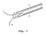
- FIG. 7is a cross-section view of a delivery catheter associated with the invention, with guide tubes positioned at the distal end of the delivery catheter.
- FIG. 8is a cross-sectional view of an electrode of the invention.
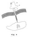
- FIG. 9is a perspective view of the tissue ablation apparatus of the invention shown in FIG. 1, with the delivery catheter being introduced percutaneously through the body and positioned at the exterior, or slightly piercing, a liver with a tumor to be ablated.
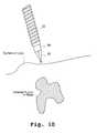
- FIG. 10is a perspective view of the tissue ablation apparatus of the invention with an obturator positioned in the delivery catheter.
- FIG. 11is a perspective view of the tissue ablation apparatus of the invention shown in FIG. 10, positioned in the body adjacent to the liver, with the obturator removed.
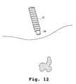
- FIG. 12is a perspective view of the tissue ablation apparatus of the invention shown in FIG. 10, positioned in the body adjacent to the liver, and the electrode deployment apparatus, with an electrode template, is positioned in the delivery catheter in place of the obturator.
- FIG. 13is a perspective view of the ablation apparatus of the invention, with deployed electrodes surrounding a tumor and defining an ablation volume.
- FIG. 14is a perspective view of the tissue ablation apparatus of the invention shown in FIG. 10, positioned in the body adjacent to the liver, with deployed electrodes surrounding a tumor and infusing a solution to the tumor site during a pre-ablation procedure.
- FIG. 15is a perspective view of the tissue ablation apparatus of the invention shown in FIG. 10, illustrating application of RF energy to the tumor.
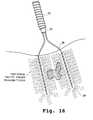
- FIG. 16is a perspective view of the tissue ablation apparatus of the invention, illustrating the electro-desiccation of the tumor.
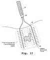
- FIG. 17is a perspective view of the tissue ablation apparatus of the invention, illustrating the instillation of solutions to the tumor site during a post-ablation procedure.
- FIG. 18illustrates bipolar ablation between electrodes of the invention.
- FIG. 19illustrates monopolar ablation between electrodes of the invention.
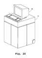
- FIG. 20is a perspective view of an ablation system of the invention, including RF and ultrasound modules, and a monitor.
- FIG. 21is a block diagram of the ablation system of the invention.
- FIG. 22 ( a )is a cross-sectional view of an RF treatment apparatus of the invention.
- FIG. 22 ( b )is a close up cross-sectional view of the distal end of the RF treatment apparatus of FIG. 22 ( a ).
- FIG. 22 ( c )is a close up cross-sectional view of the RF treatment apparatus of FIG. 22 ( a ), illustrating the proximal end of the insulation sleeve and a thermocouple associated with the insulation sleeve.
- FIG. 22 ( d )is a close up cross-sectional view of the RF treatment apparatus of FIG. 22 ( a ), illustrating the proximal end of the RF treatment apparatus of FIG. 22 ( a ).
- FIG. 23is an exploded view of an RF treatment apparatus of the invention.
- FIG. 24is a cross-sectional view of the RF treatment apparatus of the invention illustrating the electrode, insulation sleeve and the associated thermal sensors.
- FIG. 25 ( a )is a perspective view of the RF treatment apparatus of the invention with the infusion device mounted at the distal end of the catheter.
- FIG. 25 bis a perspective view of the RF treatment apparatus of FIG. 25 ( a ) illustrating the removal of the catheter, and electrode attached to the distal end of the electrode, from the infusion device which is left remaining in the body.
- FIG. 26 ( a )is a perspective view of the RF treatment apparatus of the invention with the electrode mounted at the distal end of the catheter.
- FIG. 26 ( b )is a perspective view of the RF treatment apparatus of FIG. 26 ( a ) illustrating the removal of the introducer from the lumen of the electrode.
- FIG. 27 ( a )is a perspective view of the RF treatment apparatus of the invention with the introducer removed from the lumen of the electrode.
- FIG. 27 ( b )is a perspective view of the apparatus of FIG. 27 ( a ) illustrating the removal of the electrode from the catheter, leaving behind the insulation sleeve.
- FIG. 28 ( a )is a perspective view of the RF ablation apparatus of the invention with the insulation sleeve positioned in a surrounding relationship to the electrode which is mounted to the distal end of the catheter.
- FIG. 28 ( b )is a perspective view of the RF ablation apparatus of FIG. 28 ( a ) illustrating the removal of the insulation sleeve from the electrode.
- FIG. 28 ( c )is a perspective view of the insulation sleeve after it is removed from the electrode.
- FIG. 29 ( a )is a perspective view illustrating the attachment of a syringe to the device of FIG. 27 ( a ).
- FIG. 29 ( b )is a perspective view of a syringe, containing a fluid medium such as a chemotherapeutic agent, attached to the RF ablation apparatus of FIG. 27 ( a ).
- FIG. 30is a block diagram of an RF treatment system of the invention.
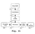
- FIG. 31is a block diagram of an embodiment of the invention which includes a microprocessor.
- FIG. 32illustrates the use of two RF treatment apparatus, such as the one illustrated in FIG. 22 ( a ), that are used in a bipolar mode.
- FIG. 1A tissue ablation apparatus 10 of the invention is illustrated in FIG. 1 .
- Ablation apparatus 10includes a delivery catheter 12 , well known to those skilled in the art, with a proximal end 14 and a distal end 16 .
- Delivery catheter 12can be of the size of about 5 to 16 F.
- a handle 18is removably attached to proximal end 14 .
- An electrode deployment deviceis at least partially positioned within delivery catheter 12 , and includes a plurality of electrodes 20 that are retractable in and out of distal end 16 .
- Electrodes 20can be of different sizes, shapes and configurations. In one embodiment, they are needle electrodes, with sizes in the range of 27 to 14 gauge. Electrodes 20 are in non-deployed positions while retained in delivery catheter.
- electrodes 20may be in a compacted state, spring loaded, generally confined or substantially straight if made of a suitable memory metal such as nitinol. As electrodes 20 are advanced out of distal end 16 they become distended in a deployed state, which defines an ablative volume, from which tissue is ablated as illustrated more fully in FIG. 2 . Electrodes 20 operate either in the bipolar or monopolar modes. When the electrodes are used in the bipolar mode, the ablative volume is substantially defined by the peripheries of the plurality of electrodes 20 . In one embodiment, the cross-sectional width of the ablative volume is about 4 cm. However, it will be appreciated that different ablative volumes can be achieved with tissue ablation apparatus 10 .
- the ablative volumeis first determined to define a mass, such as a tumor, to be ablated.
- Electrodes 20are placed in a surrounding relationship to a mass or tumor in a predetermined pattern for volumetric ablation.
- An imaging systemis used to first define the volume of the tumor or selected mass. Suitable imaging systems include but are not limited to, ultrasound, computerized tomography (CT) scanning, X-ray film, X-ray fluoroscopy, magnetic resonance imaging, electromagnetic imaging, and the like.
- CTcomputerized tomography
- an ultrasound transducertransmits ultrasound energy into a region of interest in a patient's body.
- the ultrasound energyis reflected by different organs and different tissue types. Reflected energy is sensed by the transducer, and the resulting electrical signal is processed to provide an image of the region of interest. In this way, the ablation volume is then ascertained, and the appropriate electrode deployment device is inserted into delivery catheter 12 .
- the ablative volumeis substantially defined before ablation apparatus 10 is introduced to an ablative treatment position. This assists in the appropriate positioning of ablation apparatus 10 .
- the volume of ablated tissueis reduced and substantially limited to a defined mass or tumor, including a certain area surrounding such a tumor, that is well controlled and defined. A small area around the tumor is ablated in order to ensure that all of the tumor is ablated.
- electrode sections 20 ( a )are in deployed states when they are introduced out of distal end 16 .
- electrodes 20are generally in a non-distended configuration in the non-deployed state while positioned in delivery catheter 12 , they can also be distended.
- electrode sections 20 ( b )are in retained positions while they are non-deployed.
- the electrodesare pre-sprung, confined in delivery catheter 12 , and only become sprung (expanded) as they are released from delivery catheter 12 , (ii) the electrodes are made of a memory metal, as explained in further detail below, (iii) the electrodes are made of a selectable electrode material which gives them an expanded shape outside of delivery catheter 12 , or (iv) delivery catheter 12 includes guide tubes which serve to confine electrodes 12 within delivery catheter 12 and guide their direction of travel outside of the catheter to form the desired, expanded ablation volume. As shown in FIG. 2, electrodes 20 are pre-sprung while retained in delivery catheter 12 . This is the non-deployed position.
- electrodes 20As they are advanced out of delivery catheter 12 and into tissue, electrodes 20 become deployed and begin to “fan” out from distal end 16 , moving in a lateral direction relative to a longitudinal axis of delivery catheter 12 . As deployed electrodes 20 continue their advancement, the area of the fan increases and extends beyond the diameter of distal end 16 .
- each electrode 20is distended in a deployed position, and collectively, the deployed electrodes 20 define a volume of tissue that will be ablated.
- the deployed electrodes 20define a volume of tissue that will be ablated.
- Deployed electrodes 20can have a variety of different deployed geometries including but not limited to, (i) a first section with a first radius of curvature, and a second section, extending beyond the first section, having a second radius of curvature or a substantially linear geometry, (ii) at least two radii of curvature, (iii) at least one radius of curvature in two or more planes, (iv) a curved section, with an elbow, that is located near distal end 16 of delivery catheter, and a non-curved section that extends beyond the curved section, or (v) a curved section near distal end 16 , a first linear section, and then another curved section or a second linear section that is angled with regard to the first linear section.
- Deployed electrodes 20need not be parallel with respect to each other.
- the plurality of deployed electrodes 20which define a portion of the needle electrode deployment device, can all have the same deployed geometries, i.e., all with at least two radii of curvature, or a variety of geometries, i.e., one with two radii of curvature, a second one with one radius of curvature in two planes, and the rest a curved section near distal end 16 of delivery catheter 12 and a non-curved section beyond the curved section.
- a cam 22can be positioned within delivery catheter and used to advance and retract electrodes 20 in and out of delivery catheter 12 .
- the actual movement of camcan be controlled at handle 18 .
- Suitable camsare of conventional design, well known to those skilled in the art.
- electrode 20has a first radius of curvature 20 ( c ) and a second radius of curvature 20 ( d ). It can include more than two radii of curvature. As shown in FIG. 4, electrode 20 has at least one radius of curvature which extends to three planes. In FIG. 5, each electrode has a first curved section 20 ( e ) which is near distal end 16 of delivery catheter 12 . A first generally linear section 20 ( f ) extends beyond curved section 20 ( e ), and the two meet at an elbow 20 ( g ). The electrodes 20 can serve as anodes and cathodes.
- the plurality of electrodes 20can have linear sections 20 ( f ) that are generally parallel to each other, or they can be non-parallel.
- FIG. 6illustrates an electrode 20 that includes a first curved section 20 ( e ) positioned near distal end 16 of delivery catheter 12 , a first linear section 20 ( f ), and a second linear section 20 ( h ) which extends beyond first linear section 20 ( f ).
- Section 20 ( h )can be linear, curved, or a combination of the two.
- the plurality of electrodes 20 illustrated in FIG. 6can have parallel or non-parallel first linear sections 20 ( f ).
- electrodes 20are spring-loaded, and compacted in their non-deployed positions. As electrodes 20 are advanced out of distal end 16 of delivery catheter 12 , they become deployed and fan out. Electrodes 20 continue this fanning out direction until the resistance of the tissue overcomes the strength of the material forming electrode 20 . This causes electrode 20 to bend and move in a direction inward relative to its initial outward fanning direction. The bending creates curved sections 20 ( c ) and 20 ( d ) of FIG. 3, and can also result in the formation of the other electrode 20 geometries of FIGS. 4, 5 and 6 . The extent of electrode 20 fan like travel is dependent on the strength of the material from which it is made. Suitable electrode materials include stainless steel, platinum, gold, silver, copper and other electromagnetic conducting materials including conductive polymers. Preferably, electrode 20 is made of stainless steel or nickel titanium and has dimensions of about 27 to 14 gauge.
- electrode 20is made of a memory metal, such as nickel titanium, commercially available from Raychem Corporation, Menlo Park, Calif.
- a resistive heating elementcan be positioned in an interior lumen of electrode 20 .
- Resistive heating elementcan be made of a suitable metal that transfers heat to electrode 20 , causing deployed electrode 20 to become deflected when the temperature of electrode 20 reaches a level that causes the electrode material, such as a memory metal, to deflect, as is well known in the art.
- Not all of electrode 20need be made of a memory metal. It is possible that only that distal end portion of electrode 20 , which is introduced into tissue, be made of the memory metal in order to effect the desired deployed geometrical configuration.
- mechanical devicesincluding but not limited to steering wires, can be attached to the distal end of electrode 20 to cause it to become directed, deflected and move about in a desired direction about the tissue, until it reaches its final resting position to ablate a tissue mass.
- guide tubes 24which serve to direct the expansion of electrodes 20 in the fan pattern as they are advanced out of distal end 16 of the delivery catheter 12 .
- Guide tubes 24can be made of stainless steel, spring steel and thermal plastics including but not limited to nylon and polyesters, and are of sufficient size and length to accommodate the electrodes to a specific site in the body.
- FIG. 8illustrates one embodiment of electrode 20 with a sharpened distal end 24 .
- Electrode 20can be segmented, and include a plurality of fluid distribution ports 26 , which can be evenly formed around all or only a portion of electrode 20 .
- Fluid distribution ports 26are formed in electrode 20 when it is hollow and permit the introduction and flow of a variety of fluidic mediums through electrode 20 to a desired tissue site.
- fluidic mediumsinclude, but are not limited to, electrolytic solutions, pastes or gels, as well as chemotherapeutic agents.
- suitable conductive gelsare carboxymethyl cellulose gels made from aqueous electrolyte solutions such as physiological saline solutions, and the like.
- the size of fluid distribution ports 26can vary, depending on the size and shape of electrode 20 .
- an adjustable insulator sleeve 28that is slidable along an exterior surface of electrode 20 . Insulator sleeve 28 is advanced and retracted along electrode 20 in order to define the size of a conductive surface of electrode 20 . Insulator sleeve 28 is actuated at handle 18 by the physician, and its position along electrode 20 is controlled. When electrode 20 moves out of delivery catheter 12 and into tissue, insulator sleeve 28 can be positioned around electrode 20 as it moves its way through the tissue.
- insulator sleeve 28can be advanced along a desired length of electrode 20 after electrode 20 has been positioned around a targeted mass to be ablated. Insulator sleeve is thus capable of advancing through tissue along with electrode 20 , or it can move through tissue without electrode 20 providing the source of movement.
- the desired ablation volumeis defined by deployed electrodes 20 , as well as the positioning of insulator sleeve 28 on each electrode. In this manner, a very precise ablation volume is created.
- Suitable materials that form insulator sleeveinclude but are not limited to nylon, polyimides, other thermoplastics, and the like.
- FIG. 9illustrates a percutaneous application of tissue ablation apparatus 10 .
- Tissue ablation apparatus 10can be used percutaneously to introduce electrodes 20 to the selected tissue mass or tumor. Electrodes 20 can remain in their non-deployed positions while being introduced percutaneously into the body, and delivered to a selected organ which contains the selected mass to be ablated.
- Delivery catheter 12is removable from handle 18 . When it is removed, electrode deployment device (the plurality of electrodes 20 ) can be inserted and removed from delivery catheter 12 .
- An obturator 30is inserted into delivery catheter 12 initially if a percutaneous procedure is to be performed. As shown in FIG. 10, obturator 30 can have a sharpened distal end 32 that pierces tissue and assists the introduction of delivery catheter 12 to a selected tissue site.
- the selected tissue sitecan be a body organ with a tumor or other mass, or the actual tumor itself.
- Obturator 30is then removed from delivery catheter 12 (FIG. 11 ). Electrode deployment device is then inserted into delivery catheter 12 , and the catheter is then reattached to handle 18 (FIG. 12 ). As illustrated in FIG. 12, electrode deployment device can optionally include an electrode template 34 to guide the deployment of electrodes 20 to a surrounding relationship at an exterior of a selected mass in the tissue.
- Electrodes 20are then advanced out of distal end 16 of delivery catheter 12 , and become deployed to form a desired ablative volume which surrounds the mass.
- delivery catheter 12is positioned adjacent to the liver.
- Electrode deployment deviceis introduced into delivery catheter 12 with electrode template 34 .
- Electrode deployment devicenow pierces the liver, and cam 22 advances electrodes 20 out of delivery catheter 12 into deployed positions. Each individual electrode 20 pierces the liver and travels through it until it is positioned in a surrounding relationship to the tumor.
- the ablative volumeis selectable, and determined first by imaging the area to be ablated.
- the ablative volumeis defined by the peripheries of all of the deployed electrodes 20 that surround the exterior of the tumor.
- Tissue ablation apparatus 10permits different electrode 20 sets to be inserted into delivery catheter 12 , in order to define a variety of ablation volumes.
- a pre-ablation stepPrior to ablation of the tumor, a pre-ablation step can be performed.
- a variety of different solutionsincluding electrolytic solutions such as saline, can be introduced to the tumor site, as shown in FIG. 14 .
- FIG. 15illustrates the application of RF energy to the tumor.
- Electrode insulator 28is positioned on portions of electrodes 20 where there will be no ablation. This further defines the ablation volume.
- the actual electro-desiccation of the tumor, or other targeted masses or tissues,is shown in FIG. 16 . Again, deployed electrodes 20 , with their electrode insulators 28 positioned along sections of the electrodes, define the ablation volume, and the resulting amount of mass that is desiccated.
- electrodes 20can introduce a variety of solutions in a post-ablation process. This step is illustrated in FIG. 17 . Suitable solutions include but are not limited to chemotherapeutic agents.
- FIG. 8illustrates tissue ablation apparatus 10 operated in a bipolar mode. Its monopolar operation is shown in FIG. 19 .
- Each of the plurality of electrodes 20can play different roles in the ablation process. There can be polarity shifting between the different electrodes.
- a tissue ablation system 36which can be modular, is shown in FIG. 20 and can include a display 38 .
- Tissue ablation system 36can also include an RF energy source, microwave source, ultrasound source, visualization devices such as cameras and VCR's, electrolytic and chemotherapeutic solution sources, and a controller which can be used to monitor temperature or impedance.
- One of the deployed electrodes 20can be a microwave antenna coupled to a microwave source. This electrode can initially be coupled to RF power source 42 and is then switched to the microwave source.
- a power supply 40delivers energy into RF power generator (source) 42 and then to electrodes 20 of tissue ablation apparatus 10 .
- a multiplexer 46measures current, voltage and temperature (at numerous temperature sensors which can be positioned on electrodes 20 ).
- Multiplexer 46is driven by a controller 48 , which can be a digital or analog controller, or a computer with software.
- controller 48can include a CPU coupled through a system bus. This system can include a keyboard, disk drive, or other non-volatile memory systems, a display, and other peripherals, as known in the art. Also coupled to the bus are a program memory and a data memory.
- An operator interface 50includes operator controls 52 and display 38 .
- Controller 48is coupled to imaging systems, including ultrasound transducers, temperature sensors, and viewing optics and optical fibers, if included.
- Diagnosticsare done through ultrasound, CT scanning, or other methods known in the art. Imaging can be performed before, during and after treatment.
- Temperature sensorsmeasure voltage and current that is delivered. The output of these sensors is used by controller 48 to control the delivery of RF power. Controller 48 can also control temperature and power. The amount of RF energy delivered controls the amount of power. A profile of power delivered can be incorporated in controller 38 , as well as a pre-set amount of energy to be delivered can also be profiled.
- Feedbackcan be the measurement of impedance or temperature, and occurs either at controller 48 or at electromagnetic energy source 42 , e.g., RF or microwave, if it incorporates a controller.
- electromagnetic energy source 42e.g., RF or microwave
- thiscan be achieved by supplying a small amount of non-ablation RF energy. Voltage and current are then measured.
- Circuitry, software and feedback to controller 48result in process control and are used to change, (i) power, including RF, ultrasound, and the like, (ii) the duty cycle (on-off and wattage), (iii) monopolar or bipolar energy delivery, (iv) and electrolytic solution delivery, flow rate and pressure and (v) determine when ablation is completed through time, temperature and/or impedance.
- powerincluding RF, ultrasound, and the like
- duty cycleon-off and wattage
- monopolar or bipolar energy deliveryiv
- electrolytic solution deliveryflow rate and pressure
- Treatment apparatus 110can be used to ablate a selected tissue mass, including but not limited to a tumor, or treat the mass by hyperthermia.
- Treatment apparatus 110includes a catheter 112 with a catheter lumen in which different devices are introduced and removed.
- An insert 114is removably positioned in the catheter lumen. Insert 114 can be an introducer, a needle electrode, and the like.
- insert 114When insert 114 is an introducer, including but not limited to a guiding or delivery catheter, it is used as a means for puncturing the skin of the body, and advancing catheter 112 to a desired site.
- insert 114can be both an introducer and an electrode adapted to receive RF current for tissue ablation and hyperthermia.
- Electrode 116has an electrode distal end that advances out of an insert distal end. In this deployed position, RF energy is introduced to the tissue site along a conductive surface of electrode 116 .
- Electrode 116can be included in treatment apparatus 110 , and positioned within insert 114 , while treatment apparatus 110 is being introduced to the desired tissue site.
- the distal end of electrode 116can have substantially the same geometry as the distal end of insert 114 so that the two ends are essentially flush.
- Distal end of electrode 116when positioned in insert 114 as it is introduced through the body, serves to block material from entering the lumen of insert 114 .
- the distal end of electrode 116essentially can provide a plug type of function.
- Electrode 116is then advanced out of a distal end of insert 114 , and the length of an electrode conductive surface is defined, as explained further in this specification. Electrode 116 can advance out straight, laterally or in a curved manner out of distal end of insert 114 .
- Ablative or hyperthermia treatmentbegins when two electrodes 116 are positioned closely enough to effect bipolar treatment of the desired tissue site or tumor. A return electrode attaches to the patients skin. Operating in a bipolar mode, selective ablation of the tumor is achieved.
- the present inventionis suitable for treating, through hyperthermia or ablation, different sizes of tumors or masses. The delivery of RF energy is controlled and the power at each electrode is maintained, independent of changes in voltage or current.
- Energyis delivered slowly at low power. This minimizes desiccation of the tissue adjacent to the electrodes 116 , permitting a wider area of even ablation.
- 8 to 14 W of RF energyis applied in a bipolar mode for 10 to 25 minutes.
- An ablation area between electrodes 116 of about 2 to 6 cmis achieved.
- Treatment apparatus 110can also include a removable introducer 118 which is positioned in the insert lumen instead of electrode 116 .
- Introducer 118has an introducer distal end that also serves as a plug, to minimize the entrance of material into the insert distal end as it advances through a body structure.
- Introducer 118is initially included in treatment apparatus, and is housed in the lumen of insert 114 , to assist the introduction of treatment apparatus 110 to the desired tissue site. Once treatment apparatus 110 is at the desired tissue site, then introducer 118 is removed from the insert lumen, and electrode 116 is substituted in its place. In this regard, introducer 118 and electrode 116 are removable to and from insert 114 .
- Insulator sleeve 120coupled to an insulator slide 122 .
- Insulator sleeve 120is positioned in a surrounding relationship to electrode 116 .
- Insulator slide 122imparts a slidable movement of the insulator sleeve along a longitudinal axis of electrode 116 in order to define an electrode conductive surface what begins at an insulator sleeve distal end.
- a thermal sensor 124can be positioned in or on electrode 116 or introducer 118 .
- a thermal sensor 126is positioned on insulator sleeve 120 .
- thermal sensor 124is located at the distal end of introducer 118
- thermal sensor 126is located at the distal end of insulator sleeve 120 , at an interior wall which defines a lumen of insulator sleeve 120 .
- Suitable thermal sensorsinclude a T type thermocouple with copper constantene, J type, E type, K type, thermistors, fiber optics, resistive wires, thermocouples IR detectors, and the like. It will be appreciated that sensors 124 and 126 need not be thermal sensors.
- Catheter 112 , insert 114 , electrode 116 and introducer 118can be made of a variety of materials.
- catheter 112is black anodizid aluminum, 0.5 inch
- electrode 116is made of stainless steel
- introducer 118is made of stainless steel
- insulator sleeve 120is made of polyimide.
- RF power deliverycan be accelerated to a predetermined or desired level.
- Impedanceis used to monitor voltage and current.
- the readings of thermal sensors 124 and 126are used to regulate voltage and current that is delivered to the tissue site. The output for these sensors is used by a controller, described further in this specification, to control the delivery of RF energy to the tissue site.
- Resourceswhich can be hardware and/or software, are associated with an RF power source, coupled to electrode 116 and the return electrode.
- the resourcesare associated with thermal sensors 124 and 125 , the return electrode as well as the RF power source for maintaining a selected power at electrode 116 independent of changes in voltage or current.
- Thermal sensors 124 and 126are of conventional design, including but not limited to thermistors, thermocouples, resistive wires, and the like.
- Electrode 116is preferably hollow and includes a plurality of fluid distribution ports 128 from which a variety of fluids can be introduced, including electrolytic solutions, chemotherapeutic agents, and infusion media.
- FIG. 23A specific embodiment of the RF treatment device 110 is illustrated in FIG. 23 . Included is an electrode locking cap 128 , an RF coupler 310 , an introducer locking cap 312 , insulator slide 122 , catheter body 112 , insulator retainer cap 134 , insulator locking sleeve 136 , a luer connector 138 , an insulator elbow connector 140 , an insulator adjustment screw 142 , a thermocouple cable 144 for thermal sensor 126 , a thermocouple cable 146 for thermal sensor 124 and a luer retainer 148 for an infusion device 150 .
- electrode 116is directly attached to catheter 112 without insert 114 .
- Introducer 118is slidably positioned in the lumen of electrode 116 .
- Insulator sleeve 120is again positioned in a surrounding relationship to electrode 116 and is slidably moveable along its surface in order to define the conductive surface.
- Thermal sensors 124 and 126are positioned at the distal ends of introducer 118 and insulator sleeve 120 .
- thermal sensor 124can be positioned on electrode 116 , such as at its distal end.
- the distal ends of electrode 116 and introducer 118can be sharpened and tapered. This assists in the introduction of RF treatment apparatus to the desired tissue site.
- Each of the two distal endscan have geometries that essentially match.
- distal end of introducer 118can an essentially solid end in order to prevent the introduction of material into the lumen of catheter 116 .
- infusion device 150remains implanted in the body after catheter 112 , electrode 116 and introducer 118 are all removed. This permits a chemotherapeutic agent, or other infusion medium, to be easily introduced to the tissue site over an extended period of time without the other devices of RF treatment apparatus 110 present. These other devices, such as electrode 116 , can be inserted through infusion device 150 to the tissue site at a later time for hyperthermia or ablation purposes.
- Infusion device 150has an infusion device lumen and catheter 112 is at least partially positioned in the infusion device lumen. Electrode 116 is positioned in the catheter lumen, in a fixed relationship to catheter 112 , but is removable from the lumen.
- Insulator sleeve 120is slidably positioned along a longitudinal axis of electrode 116 .
- Introducer 118is positioned in a lumen of electrode 116 and is removable therefrom.
- a power sourceis coupled to electrode 116 .
- Resourcesare associated with thermal sensors 124 and 126 , voltage and current sensors that are coupled to the RF power source for maintaining a selected power at electrode 116 .
- FIG. 22 ( b )The distal end of RF treatment apparatus 110 is shown in FIG. 22 ( b ).
- Introducer 118is positioned in the lumen of electrode 116 , which can be surrounded by insulator sleeve 120 , all of which are essentially placed in the lumen of infusion device 150 . It will be appreciated, however, that in FIG. 22 ( b ) insert 114 can take the place of electrode 116 , and electrode 116 can be substituted for introducer 118 .
- thermal sensor 126is shown as being in the form of a thermocouple.
- thermal sensor 124is also illustrated as a thermocouple that extends beyond a distal end of introducer 118 , or alternative a distal end of electrode 116 .
- infusion device 150is attached to the distal end of catheter 112 and retained by a collar.
- the collaris rotated, causing catheter 112 to become disengaged from infusion device 150 .
- Electrode 116is attached to the distal end of catheter 112 .
- Catheter 112is pulled away from infusion device 150 , which also removes electrode 116 from infusion device 150 . Thereafter, only infusion device 150 is retained in the body. While it remains placed, chemotherapeutic agents can be introduced through infusion device 150 to treat the tumor site. Additionally, by leaving infusion device 150 in place, catheter 112 with electrode 116 can be reintroduced back into the lumen of infusion device 150 at a later time for additional RF treatment in the form of ablation or hyperthermia.
- electrode 116is shown as attached to the distal end of catheter 112 .
- Introducer 118is attached to introducer locking cap 132 which is rotated and pulled away from catheter 112 . As shown in FIG. 26 ( b ) this removes introducer 118 from the lumen of electrode 116 .
- electrode 116is at least partially positioned in the lumen of catheter 112 .
- Electrode locking cap 128is mounted at the proximal end of catheter 112 , with the proximal end of electrode 116 attaching to electrode locking cap 128 .
- Electrode locking cap 128is rotated and unlocks from catheter 112 .
- electrode locking cap 128is then pulled away from the proximal end of catheter 112 , pulling with it electrode 116 which is then removed from the lumen of catheter 112 .
- insulator sleeve 120is locked on catheter 112 by insulator retainer cap 134 .
- FIG. 28 ( a )insulator retainer cap 134 is unlocked and removed from catheter 112 . As shown in FIG. 28 ( b ), insulator sleeve 120 is then slid off of electrode 116 . FIG. 28 ( c ) illustrates insulator sleeve 120 completely removed from catheter 112 and electrode 116 .
- a fluid sourcesuch as syringe 151 , delivering a suitable fluid, including but not limited to a chemotherapeutic agent, attaches to luer connector 138 at the proximal end of catheter 112 .
- a suitable fluidincluding but not limited to a chemotherapeutic agent
- Chemotherapeutic agentsare then delivered from syringe 151 through electrode 116 to the tumor site.
- Syringe 151is then removed from catheter 112 by imparting a rotational movement of syringe 151 and pulling it away from catheter 112 . Thereafter, electrode 116 can deliver further RF power to the tumor site.
- electrode 116 and catheter 112can be removed, leaving only infusion device 150 in the body.
- Syringe 151can then be attached directly to infusion device 150 to introduce a chemotherapeutic agent to the tumor site.
- other fluid delivery devicescan be coupled to infusion device 150 in order to have a more sustained supply of chemotherapeutic agents to the tumor site.
- electrode 116 and catheter 112can be introduced through infusion device 150 .
- RF poweris then delivered to the tumor site. The process begins again with the subsequent removal of catheter 112 and electrode 116 from infusion device 150 . Chemotherapy can then begin. Once it is complete, further RF power can be delivered to the tumor site. This process can be repeated any number of times for an effective multi-modality treatment of the tumor site.
- Power source 152includes a power supply 154 , power circuits 156 , a controller 158 , a power and impedance calculation device 160 , a current sensor 162 , a voltage sensor 164 , a temperature measurement device 166 and a user interface and display 168 .
- FIGS. 31 ( a ) through 31 ( g )are schematic diagrams of power supply 154 , voltage sensor 164 , current sensor 162 , power computing circuit associated with power and impedance calculation device 160 , impedance computing circuit associated with power and impedance calculation device 160 , power control circuit of controller 158 and an eight channel temperature measurement circuit of temperature measure device 166 , respectively.
- a control signalis generated by controller 158 that is proportional to the difference between an actual measured value, and a desired value.
- the control signalis used by power circuits 156 to adjust the power output in an appropriate amount in order to maintain the desired power delivered at the respective electrode 116 .
- temperatures detected at thermal sensors 124 and 126provide feedback for maintaining a selected power.
- the actual temperaturesare measured at temperature measurement device 166 , and the temperatures are displayed at user interface 168 .
- a control signalis generated by controller 159 that is proportional to the difference between an actual measured temperature, and a desired temperature.
- the control signalis used by power circuits 157 to adjust the power output in an appropriate amount in order to maintain the desired temperature delivered at the respective sensor 124 or 126 .
- Controller 158can be a digital or analog controller, or a computer with software.
- controller 158is a computer it can include a CPU coupled through a system bus.
- On this systemcan be a keyboard, a disk drive, or other non-volatile memory systems, a display, and other peripherals, as are known in the art.
- Also coupled to the busare a program memory and a data memory.
- User interface 168includes operator controls and a display. Controller 158 can be coupled to imaging systems, including but not limited to ultrasound, CT scanners and the like.
- Diagnosticscan be performed optically, with ultrasound, CT scanning, and the like. Diagnostics are performed either before, during and after treatment.
- the output of current sensor 162 and voltage sensor 164is used by controller 158 to maintain the selected power level at electrodes 116 .
- the amount of RF energy deliveredcontrols the amount of power.
- a profile of power deliveredcan be incorporated in controller 158 , and a pre-set amount of energy to be delivered can also be profiled.
- Circuitry, software and feedback to controller 158result in process control, and the maintenance of the selected power that is independent of changes in voltage or current, and are used to change, (i) the selected power, including RF, ultrasound and the like, (ii) the duty cycle (on-off and wattage), (iii) bipolar energy delivery and (iv) fluid delivery, including chemotherapeutic agents, flow rate and pressure.
- process variablesare controlled and varied, while maintaining the desired delivery of power independent of changes in voltage or current, based on temperatures monitored at thermal sensors 124 and 126 at multiple sites.
- Controller 158can be microprocessor controlled. Referring now to FIG. 31, current sensor 162 and voltage sensor 164 are connected to the input of an analog amplifier 170 .
- Analog amplifier 170can be a conventional differential amplifier circuit for use with thermal sensors 124 and 126 .
- the output of analog amplifier 170is sequentially connected by an analog multiplexer 172 to the input of analog-to-digital converter 174 .
- the output of analog amplifier 170is a voltage which represents the respective sensed temperatures. Digitized amplifier output voltages are supplied by analog-to-digital converter 174 to a microprocessor 176 .
- Microprocessor 176may be a type 68HCII available from Motorola. However, it will be appreciated that any suitable microprocessor or general purpose digital or analog computer can be used to calculate impedance or temperature.
- Microprocessor 176sequentially receives and stores digital representations of impedance and temperature. Each digital value received by microprocessor 176 corresponds to different temperatures and impedances.
- Calculated power and impedance valuescan be indicated on user interface 168 .
- calculated impedance and power valuescan be compared by microprocessor 176 with power and impedance limits. When the values exceed predetermined power or impedance values, a warning can be given on interface 168 , and additionally, the delivery of RF energy can be reduced, modified or interrupted.
- a control signal from microprocessor 176can modify the power level supplied by power supply 154 .
- An imaging systemcan be used to first define the volume of the tumor or selected mass.
- Suitable imaging systemsinclude but are not limited to, ultrasound, CT scanning, X-ray film, X-ray fluoroscope, magnetic resonance imaging, electromagnetic imaging and the like. The use of such devices to define a volume of a tissue mass or a tumor is well known to those skilled in the art.
- an ultrasound transducertransmits ultrasound energy into a region of interest in a patient's body.
- the ultrasound energyis reflected by different organs and different tissue types. Reflected energy is sensed by the transducer, and the resulting electrical signal is processed to provide an image of the region of interest. In this way, the volume to be ablated is ascertained.
- Ultrasoundis employed to image the selected mass or tumor. This image is then imported to user interface 168 .
- the placement of electrodes 116can be marked, and RF energy delivered to the selected site with prior treatment planning.
- Ultrasoundcan be used for real time imaging. Tissue characterization of the imaging can be utilized to determine how much of the tissue is heated. This process can be monitored. The amount of RF power delivered is low, and the ablation or hyperthermia of the tissue is slow. Desiccation of tissue between the tissue and each needle 116 is minimized by operating at low power.
- Exposed electrode length1.5 Distance between electrodes 2.0 Power setting 7.0 Ablation time 10 min.
- Lesion size width2.8 cm length 2.5 cm depth 2.2 cm
Landscapes
- Health & Medical Sciences (AREA)
- Engineering & Computer Science (AREA)
- Life Sciences & Earth Sciences (AREA)
- Biomedical Technology (AREA)
- Surgery (AREA)
- Veterinary Medicine (AREA)
- General Health & Medical Sciences (AREA)
- Nuclear Medicine, Radiotherapy & Molecular Imaging (AREA)
- Chemical & Material Sciences (AREA)
- Public Health (AREA)
- Animal Behavior & Ethology (AREA)
- Physics & Mathematics (AREA)
- Molecular Biology (AREA)
- Medical Informatics (AREA)
- Heart & Thoracic Surgery (AREA)
- Otolaryngology (AREA)
- Materials Engineering (AREA)
- Mechanical Engineering (AREA)
- Radiology & Medical Imaging (AREA)
- Metallurgy (AREA)
- Organic Chemistry (AREA)
- Plasma & Fusion (AREA)
- Pathology (AREA)
- Electromagnetism (AREA)
- Crystallography & Structural Chemistry (AREA)
- Thermal Sciences (AREA)
- Surgical Instruments (AREA)
Abstract
Description
| Exposed electrode length | 1.5 cm | ||
| Distance between electrodes | 1.5 cm | ||
| Power setting | 5 | ||
| Ablation time | |||
| 10 min. | |||
| Lesion size | |||
| width | 2 cm | ||
| length | 1.7 cm | ||
| depth | 1.5 cm | ||
| Exposed electrode length | 1.5 | ||
| Distance between electrodes | 2.0 | ||
| Power setting | 7.0 | ||
| 10 min. | |||
| Lesion size | |||
| width | 2.8 cm | ||
| length | 2.5 cm | ||
| depth | 2.2 cm | ||
| Exposed electrode length | 2.5 cm | ||
| Distance between electrodes | 2.0 cm | ||
| Power setting | 10 | ||
| Ablation time | |||
| 10 min | |||
| Lesion size | |||
| width | 3.0 cm | ||
| length | 2.7 cm | ||
| depth | 1.7 cm | ||
| Exposed electrode length | 2.5 cm | ||
| Distance between electrodes | 2.5 cm | ||
| Power setting | 8 | ||
| Ablation time | |||
| 10 min. | |||
| Lesion size | |||
| width | 2.8 cm | ||
| length | 2.7 cm | ||
| depth | 3.0 cm | ||
| Exposed electrode length | 2.5 cm | ||
| Distance between electrodes | 2.5 cm | ||
| Power setting | 8 | ||
| Ablation time | |||
| 12 min. | |||
| Lesion size | |||
| width | 2.8 cm | ||
| length | 2.8 cm | ||
| depth | 2.5 cm | ||
| Exposed electrode length | 2.5 cm | ||
| Distance between electrodes | 1.5 cm | ||
| Power setting | 8 | ||
| Ablation time | |||
| 14 min. | |||
| Lesion size | |||
| width | 3.0 cm | ||
| length | 3.0 cm | ||
| depth | 2.0 cm | ||
| With return electrode at 1.5 cm |
| Exposed electrode length | 2.5 cm | ||
| Distance between electrodes | 2.5 cm | ||
| Power setting | 8 | ||
| Ablation time | |||
| 10 min. | |||
| Lesion size | |||
| width | 3.0 cm | ||
| length | 3.0 cm | ||
| depth | 3.0 cm | ||
| Exposed electrode length | 2.5 cm | ||
| Distance between electrodes | 2.5 cm | ||
| Power setting | 10 | ||
| Ablation time | |||
| 12 min. | |||
| Lesion size | |||
| width | 3.5 cm | ||
| length | 3.0 cm | ||
| depth | 2.3 cm | ||
| Exposed electrode length | 2.5 cm | ||
| Distance between electrodes | 2.5 cm | ||
| Power setting | 11 W | ||
| Ablation time | 11 min. | ||
| Lesion size | |||
| width | 3.5 cm | ||
| length | 3.5 cm | ||
| depth | 2.5 cm | ||
| Exposed electrode length | 3.0 cm | ||
| Distance between electrodes | 3.0 cm | ||
| Power setting | 11 W | ||
| Ablation time | 15 min. | ||
| Lesion size | |||
| width | 4.3 cm | ||
| length | 3.0 cm | ||
| depth | 2.2 cm | ||
| Exposed electrode length | 3.0 cm | ||
| Distance between electrodes | 2.5 cm | ||
| Power setting | 11 W | ||
| Ablation time | 11 min. | ||
| Lesion size | |||
| width | 4.0 cm | ||
| length | 3.0 cm | ||
| depth | 2.2 cm | ||
| Exposed electrode length | 4.0 cm | ||
| Distance between electrodes | 2.5 cm | ||
| Power setting | 11 | ||
| Ablation time | |||
| 16 min. | |||
| Lesion size | |||
| width | 3.5 cm | ||
| length | 4.0 cm | ||
| depth | 2.8 cm | ||
| Two pairs of electrodes (Four electrodes) |
| Exposed electrode length | 2.5 cm | ||
| Distance between electrodes | 2.5 cm | ||
| Power setting | 12 | ||
| Ablation time | |||
| 16 min. | |||
| Lesion size | |||
| width | 3.5 cm | ||
| length | 3.0 cm | ||
| depth | 4.5 cm | ||
| Two pairs of electrodes (Four electrodes) |
| Exposed electrode length | 2.5 cm | ||
| Distance between electrodes | 2.5 cm | ||
| Power setting | 15 | ||
| Ablation time | |||
| 14 min. | |||
| Lesion size | |||
| width | 4.0 cm | ||
| length | 3.0 cm | ||
| depth | 5.0 cm | ||
Claims (16)
Priority Applications (1)
| Application Number | Priority Date | Filing Date | Title |
|---|---|---|---|
| US09/513,727US6569159B1 (en) | 1993-11-08 | 2000-02-24 | Cell necrosis apparatus |
Applications Claiming Priority (9)
| Application Number | Priority Date | Filing Date | Title |
|---|---|---|---|
| US08/148,439US5458597A (en) | 1993-11-08 | 1993-11-08 | Device for treating cancer and non-malignant tumors and methods |
| US08/290,031US5536267A (en) | 1993-11-08 | 1994-08-12 | Multiple electrode ablation apparatus |
| US08/295,166US5599345A (en) | 1993-11-08 | 1994-08-24 | RF treatment apparatus |
| US08/515,379US5683384A (en) | 1993-11-08 | 1995-08-15 | Multiple antenna ablation apparatus |
| US08/623,652US5935123A (en) | 1993-11-08 | 1996-03-29 | RF treatment apparatus |
| US08/802,195US6071280A (en) | 1993-11-08 | 1997-02-14 | Multiple electrode ablation apparatus |
| US09/364,203US6663624B2 (en) | 1993-11-08 | 1999-07-30 | RF treatment apparatus |
| US09/383,166US6471698B1 (en) | 1993-11-08 | 1999-08-25 | Multiple electrode ablation apparatus |
| US09/513,727US6569159B1 (en) | 1993-11-08 | 2000-02-24 | Cell necrosis apparatus |
Related Parent Applications (2)
| Application Number | Title | Priority Date | Filing Date |
|---|---|---|---|
| US09/364,203Continuation-In-PartUS6663624B2 (en) | 1993-11-08 | 1999-07-30 | RF treatment apparatus |
| US09/383,166Continuation-In-PartUS6471698B1 (en) | 1993-11-08 | 1999-08-25 | Multiple electrode ablation apparatus |
Related Child Applications (1)
| Application Number | Title | Priority Date | Filing Date |
|---|---|---|---|
| US08/290,031Continuation-In-PartUS5536267A (en) | 1993-11-08 | 1994-08-12 | Multiple electrode ablation apparatus |
Publications (1)
| Publication Number | Publication Date |
|---|---|
| US6569159B1true US6569159B1 (en) | 2003-05-27 |
Family
ID=46279617
Family Applications (1)
| Application Number | Title | Priority Date | Filing Date |
|---|---|---|---|
| US09/513,727Expired - Fee RelatedUS6569159B1 (en) | 1993-11-08 | 2000-02-24 | Cell necrosis apparatus |
Country Status (1)
| Country | Link |
|---|---|
| US (1) | US6569159B1 (en) |
Cited By (157)
| Publication number | Priority date | Publication date | Assignee | Title |
|---|---|---|---|---|
| US20030109862A1 (en)* | 2001-11-02 | 2003-06-12 | Mani Prakash | High-strength microwave antenna assemblies and methods of use |
| US20030120267A1 (en)* | 2001-04-30 | 2003-06-26 | Kaufman Cary S. | Percutaneous device for site specific delivery and method of use |
| US20030195499A1 (en)* | 2002-04-16 | 2003-10-16 | Mani Prakash | Microwave antenna having a curved configuration |
| US20030195500A1 (en)* | 1999-06-17 | 2003-10-16 | Moorman Jack W. | Needle kit and method for microwave ablation, track coagulation, and biopsy |
| US20040077951A1 (en)* | 2002-07-05 | 2004-04-22 | Wei-Chiang Lin | Apparatus and methods of detection of radiation injury using optical spectroscopy |
| US20050015081A1 (en)* | 2003-07-18 | 2005-01-20 | Roman Turovskiy | Devices and methods for cooling microwave antennas |
| US20050049586A1 (en)* | 2003-07-11 | 2005-03-03 | Daniel Steven A. | Thermal ablation of biological tissue |
| US20050062666A1 (en)* | 2001-11-02 | 2005-03-24 | Vivant Medical, Inc. | High-strength microwave antenna assemblies |
| US20050070768A1 (en)* | 2003-09-30 | 2005-03-31 | Qingsheng Zhu | Sensors having protective eluting coating and method therefor |
| US6878146B2 (en)* | 2001-03-16 | 2005-04-12 | Gr Originals, L.L.C. | Apparatus for treatment and prevention of alopecia |
| US20050190982A1 (en)* | 2003-11-28 | 2005-09-01 | Matsushita Electric Industrial Co., Ltd. | Image reducing device and image reducing method |
| RU2271209C1 (en)* | 2004-08-12 | 2006-03-10 | Сергей Борисович Авакимян | Method for treating malignant tumors |
| US20060122593A1 (en)* | 2003-04-24 | 2006-06-08 | Myong-Ki Jun | Electrode for radiofrequency tissue ablation |
| US20060129144A1 (en)* | 2003-02-19 | 2006-06-15 | Shin Kyong M | Electrode device for high frequency thermotherapy |
| US20060173359A1 (en)* | 2002-09-30 | 2006-08-03 | Lin Wei C | Optical apparatus for guided liver tumor treatment and methods |
| US20060189972A1 (en)* | 2005-02-02 | 2006-08-24 | Gynesonics, Inc. | Method and device for uterine fibroid treatment |
| US20060212032A1 (en)* | 2005-01-18 | 2006-09-21 | Daniel Steven A | Device and method for thermal ablation of biological tissue using spherical ablation patterns |
| US20060259024A1 (en)* | 2005-05-10 | 2006-11-16 | Roman Turovskiy | Reinforced high strength microwave antenna |
| US20070032798A1 (en)* | 2005-08-08 | 2007-02-08 | Pantages Anthony J | Vascular suturing device with needle capture |
| US20070049968A1 (en)* | 2005-08-24 | 2007-03-01 | Sibbitt Wilmer L Jr | Vascular opening edge eversion methods and apparatuses |
| US20070049967A1 (en)* | 2005-08-24 | 2007-03-01 | Sibbitt Wilmer L Jr | Vascular closure methods and apparatuses |
| US20070161905A1 (en)* | 2006-01-12 | 2007-07-12 | Gynesonics, Inc. | Intrauterine ultrasound and method for use |
| US20070179380A1 (en)* | 2006-01-12 | 2007-08-02 | Gynesonics, Inc. | Interventional deployment and imaging system |
| US20070249939A1 (en)* | 2006-04-20 | 2007-10-25 | Gynesonics, Inc. | Rigid delivery systems having inclined ultrasound and curved needle |
| US20080183165A1 (en)* | 2007-01-31 | 2008-07-31 | Steven Paul Buysse | Thermal Feedback Systems and Methods of Using the Same |
| EP1784138A4 (en)* | 2004-09-03 | 2008-09-10 | Diros Technology Inc | Method and apparatus for delivering energy via a hybrid cannula/electrode medical device |
| WO2008084244A3 (en)* | 2007-01-11 | 2008-10-02 | Emcision Ltd | Device and method for the treatment of diseased tissue such as tumours |
| US20080294162A1 (en)* | 2007-05-22 | 2008-11-27 | Francesca Rossetto | Energy delivery conduits for use with electrosugical devices |
| WO2008101091A3 (en)* | 2007-02-15 | 2008-11-27 | Ethicon Endo Surgery Inc | Electrical ablation apparatus, system, and method |
| US7468042B2 (en) | 2002-04-16 | 2008-12-23 | Vivant Medical, Inc. | Localization element with energized tip |
| US20090005766A1 (en)* | 2007-06-28 | 2009-01-01 | Joseph Brannan | Broadband microwave applicator |
| US20090088779A1 (en)* | 1999-03-04 | 2009-04-02 | Abbott Laboratories | Articulating Suturing Device and Method |
| US20090099544A1 (en)* | 2007-10-12 | 2009-04-16 | Gynesonics, Inc. | Methods and systems for controlled deployment of needles in tissue |
| US20090182332A1 (en)* | 2008-01-15 | 2009-07-16 | Ethicon Endo-Surgery, Inc. | In-line electrosurgical forceps |
| US20090254119A1 (en)* | 2005-08-24 | 2009-10-08 | Avasca Medical Inc. | Vascular Closure Methods and Apparatuses |
| US20090262982A1 (en)* | 2008-04-18 | 2009-10-22 | Markowitz H Toby | Determining a Location of a Member |
| US20090264746A1 (en)* | 2008-04-18 | 2009-10-22 | Markowitz H Toby | Tracking a guide member |
| US20090264739A1 (en)* | 2008-04-18 | 2009-10-22 | Markowitz H Toby | Determining a position of a member within a sheath |
| US20090281540A1 (en)* | 2008-05-06 | 2009-11-12 | Blomgren Richard D | Apparatus, Systems and Methods for Treating a Human Tissue Condition |
| US20090287081A1 (en)* | 2008-04-29 | 2009-11-19 | Gynesonics , Inc | Submucosal fibroid ablation for the treatment of menorrhagia |
| US20090292211A1 (en)* | 2002-07-05 | 2009-11-26 | Vanderbilt University | Methods and Apparatus for Optical Spectroscopic Detection of Cell and Tissue Death |
| US20090297001A1 (en)* | 2008-04-18 | 2009-12-03 | Markowitz H Toby | Method And Apparatus For Mapping A Structure |
| US20090306658A1 (en)* | 2008-06-05 | 2009-12-10 | Ethicon Endo-Surgery, Inc. | Manually articulating devices |
| US7655004B2 (en) | 2007-02-15 | 2010-02-02 | Ethicon Endo-Surgery, Inc. | Electroporation ablation apparatus, system, and method |
| US20100056926A1 (en)* | 2008-08-26 | 2010-03-04 | Gynesonics, Inc. | Ablation device with articulated imaging transducer |
| US7678108B2 (en)* | 2004-06-02 | 2010-03-16 | Medtronic, Inc. | Loop ablation apparatus and method |
| US20100262068A1 (en)* | 2009-04-10 | 2010-10-14 | Promoitalia Group S.P.A. | Method for creating an autologous radiofrequency capsule for containing filling solutions |
| US7815662B2 (en) | 2007-03-08 | 2010-10-19 | Ethicon Endo-Surgery, Inc. | Surgical suture anchors and deployment device |
| EP2253286A1 (en)* | 2009-05-19 | 2010-11-24 | Vivant Medical, Inc. | Tissue impedance measurement using a secondary frequency |
| US20100298825A1 (en)* | 2009-05-08 | 2010-11-25 | Cellutions, Inc. | Treatment System With A Pulse Forming Network For Achieving Plasma In Tissue |
| US7874986B2 (en) | 2006-04-20 | 2011-01-25 | Gynesonics, Inc. | Methods and devices for visualization and ablation of tissue |
| US7931669B2 (en) | 2000-01-05 | 2011-04-26 | Integrated Vascular Systems, Inc. | Integrated vascular device with puncture site closure component and sealant and methods of use |
| US20110098694A1 (en)* | 2009-10-28 | 2011-04-28 | Ethicon Endo-Surgery, Inc. | Methods and instruments for treating cardiac tissue through a natural orifice |
| US20110160721A1 (en)* | 2009-12-31 | 2011-06-30 | Huisun Wang | Irrigated Catheter Employing Multi-Lumenal Irrigation Tubing |
| US20110190630A1 (en)* | 2010-01-29 | 2011-08-04 | Steven Kim | System and Method for Performing An Electrosurgical Procedure Using An Ablation Device With An Integrated Imaging Device |
| US7998139B2 (en) | 2007-04-25 | 2011-08-16 | Vivant Medical, Inc. | Cooled helical antenna for microwave ablation |
| US20110208180A1 (en)* | 2010-02-25 | 2011-08-25 | Vivant Medical, Inc. | System and Method for Monitoring Ablation Size |
| US8037591B2 (en) | 2009-02-02 | 2011-10-18 | Ethicon Endo-Surgery, Inc. | Surgical scissors |
| US8038688B2 (en) | 1999-03-04 | 2011-10-18 | Abbott Laboratories | Articulating suturing device and method |
| US8068921B2 (en) | 2006-09-29 | 2011-11-29 | Vivant Medical, Inc. | Microwave antenna assembly and method of using the same |
| US8070759B2 (en) | 2008-05-30 | 2011-12-06 | Ethicon Endo-Surgery, Inc. | Surgical fastening device |
| US8075572B2 (en) | 2007-04-26 | 2011-12-13 | Ethicon Endo-Surgery, Inc. | Surgical suturing apparatus |
| US8100922B2 (en) | 2007-04-27 | 2012-01-24 | Ethicon Endo-Surgery, Inc. | Curved needle suturing tool |
| US8114072B2 (en) | 2008-05-30 | 2012-02-14 | Ethicon Endo-Surgery, Inc. | Electrical ablation device |
| US8114119B2 (en) | 2008-09-09 | 2012-02-14 | Ethicon Endo-Surgery, Inc. | Surgical grasping device |
| US8128644B2 (en) | 2000-12-07 | 2012-03-06 | Integrated Vascular Systems, Inc. | Closure device and methods for making and using them |
| US8157834B2 (en) | 2008-11-25 | 2012-04-17 | Ethicon Endo-Surgery, Inc. | Rotational coupling device for surgical instrument with flexible actuators |
| US8172772B2 (en) | 2008-12-11 | 2012-05-08 | Ethicon Endo-Surgery, Inc. | Specimen retrieval device |
| US8206300B2 (en) | 2008-08-26 | 2012-06-26 | Gynesonics, Inc. | Ablation device with articulated imaging transducer |
| US8211125B2 (en) | 2008-08-15 | 2012-07-03 | Ethicon Endo-Surgery, Inc. | Sterile appliance delivery device for endoscopic procedures |
| US8241204B2 (en) | 2008-08-29 | 2012-08-14 | Ethicon Endo-Surgery, Inc. | Articulating end cap |
| US8252057B2 (en) | 2009-01-30 | 2012-08-28 | Ethicon Endo-Surgery, Inc. | Surgical access device |
| US8262680B2 (en) | 2008-03-10 | 2012-09-11 | Ethicon Endo-Surgery, Inc. | Anastomotic device |
| US8262563B2 (en) | 2008-07-14 | 2012-09-11 | Ethicon Endo-Surgery, Inc. | Endoscopic translumenal articulatable steerable overtube |
| US8262574B2 (en) | 2009-02-27 | 2012-09-11 | Gynesonics, Inc. | Needle and tine deployment mechanism |
| US8262655B2 (en) | 2007-11-21 | 2012-09-11 | Ethicon Endo-Surgery, Inc. | Bipolar forceps |
| US8292880B2 (en) | 2007-11-27 | 2012-10-23 | Vivant Medical, Inc. | Targeted cooling of deployable microwave antenna |
| US8299014B2 (en) | 2009-01-28 | 2012-10-30 | Clean Technology International Corporation | Material for facilitating thermal treatments of biological tissues and method of energy targeting leading to thermal treatment of biological tissues |
| US8313497B2 (en) | 2005-07-01 | 2012-11-20 | Abbott Laboratories | Clip applier and methods of use |
| US8317806B2 (en) | 2008-05-30 | 2012-11-27 | Ethicon Endo-Surgery, Inc. | Endoscopic suturing tension controlling and indication devices |
| US8337394B2 (en) | 2008-10-01 | 2012-12-25 | Ethicon Endo-Surgery, Inc. | Overtube with expandable tip |
| US8353487B2 (en) | 2009-12-17 | 2013-01-15 | Ethicon Endo-Surgery, Inc. | User interface support devices for endoscopic surgical instruments |
| US8361066B2 (en) | 2009-01-12 | 2013-01-29 | Ethicon Endo-Surgery, Inc. | Electrical ablation devices |
| US8361088B2 (en) | 2003-09-26 | 2013-01-29 | Abbott Laboratories | Device and method for suturing intracardiac defects |
| US8361112B2 (en) | 2008-06-27 | 2013-01-29 | Ethicon Endo-Surgery, Inc. | Surgical suture arrangement |
| US8409200B2 (en) | 2008-09-03 | 2013-04-02 | Ethicon Endo-Surgery, Inc. | Surgical grasping device |
| US8480657B2 (en) | 2007-10-31 | 2013-07-09 | Ethicon Endo-Surgery, Inc. | Detachable distal overtube section and methods for forming a sealable opening in the wall of an organ |
| US8480689B2 (en) | 2008-09-02 | 2013-07-09 | Ethicon Endo-Surgery, Inc. | Suturing device |
| US8496574B2 (en) | 2009-12-17 | 2013-07-30 | Ethicon Endo-Surgery, Inc. | Selectively positionable camera for surgical guide tube assembly |
| US8506564B2 (en) | 2009-12-18 | 2013-08-13 | Ethicon Endo-Surgery, Inc. | Surgical instrument comprising an electrode |
| US8529563B2 (en) | 2008-08-25 | 2013-09-10 | Ethicon Endo-Surgery, Inc. | Electrical ablation devices |
| US8568410B2 (en) | 2007-08-31 | 2013-10-29 | Ethicon Endo-Surgery, Inc. | Electrical ablation surgical instruments |
| US8574244B2 (en) | 2007-06-25 | 2013-11-05 | Abbott Laboratories | System for closing a puncture in a vessel wall |
| US8579897B2 (en) | 2007-11-21 | 2013-11-12 | Ethicon Endo-Surgery, Inc. | Bipolar forceps |
| US8579932B2 (en) | 2002-02-21 | 2013-11-12 | Integrated Vascular Systems, Inc. | Sheath apparatus and methods for delivering a closure device |
| US8590760B2 (en) | 2004-05-25 | 2013-11-26 | Abbott Vascular Inc. | Surgical stapler |
| US8603136B2 (en) | 2000-12-07 | 2013-12-10 | Integrated Vascular Systems, Inc. | Apparatus and methods for providing tactile feedback while delivering a closure device |
| US8608652B2 (en) | 2009-11-05 | 2013-12-17 | Ethicon Endo-Surgery, Inc. | Vaginal entry surgical devices, kit, system, and method |
| US8651146B2 (en) | 2007-09-28 | 2014-02-18 | Covidien Lp | Cable stand-off |
| US8652150B2 (en) | 2008-05-30 | 2014-02-18 | Ethicon Endo-Surgery, Inc. | Multifunction surgical device |
| US8679003B2 (en) | 2008-05-30 | 2014-03-25 | Ethicon Endo-Surgery, Inc. | Surgical device and endoscope including same |
| US8690910B2 (en) | 2000-12-07 | 2014-04-08 | Integrated Vascular Systems, Inc. | Closure device and methods for making and using them |
| US8731641B2 (en) | 2008-12-16 | 2014-05-20 | Medtronic Navigation, Inc. | Combination of electromagnetic and electropotential localization |
| US8758396B2 (en) | 2000-01-05 | 2014-06-24 | Integrated Vascular Systems, Inc. | Vascular sheath with bioabsorbable puncture site closure apparatus and methods of use |
| US8771260B2 (en) | 2008-05-30 | 2014-07-08 | Ethicon Endo-Surgery, Inc. | Actuating and articulating surgical device |
| US8784447B2 (en) | 2000-09-08 | 2014-07-22 | Abbott Vascular Inc. | Surgical stapler |
| US8808310B2 (en) | 2006-04-20 | 2014-08-19 | Integrated Vascular Systems, Inc. | Resettable clip applier and reset tools |
| US8828031B2 (en) | 2009-01-12 | 2014-09-09 | Ethicon Endo-Surgery, Inc. | Apparatus for forming an anastomosis |
| CN104107090A (en)* | 2013-04-19 | 2014-10-22 | 山东威高集团医用高分子制品股份有限公司 | Disposable bipolar probing needle |
| US8888792B2 (en) | 2008-07-14 | 2014-11-18 | Ethicon Endo-Surgery, Inc. | Tissue apposition clip application devices and methods |
| US8893947B2 (en) | 2007-12-17 | 2014-11-25 | Abbott Laboratories | Clip applier and methods of use |
| US8906035B2 (en) | 2008-06-04 | 2014-12-09 | Ethicon Endo-Surgery, Inc. | Endoscopic drop off bag |
| US8905937B2 (en) | 2009-02-26 | 2014-12-09 | Integrated Vascular Systems, Inc. | Methods and apparatus for locating a surface of a body lumen |
| US8926633B2 (en) | 2005-06-24 | 2015-01-06 | Abbott Laboratories | Apparatus and method for delivering a closure element |
| US8939897B2 (en) | 2007-10-31 | 2015-01-27 | Ethicon Endo-Surgery, Inc. | Methods for closing a gastrotomy |
| US8986199B2 (en) | 2012-02-17 | 2015-03-24 | Ethicon Endo-Surgery, Inc. | Apparatus and methods for cleaning the lens of an endoscope |
| US9005198B2 (en) | 2010-01-29 | 2015-04-14 | Ethicon Endo-Surgery, Inc. | Surgical instrument comprising an electrode |
| US9023024B2 (en) | 2007-06-20 | 2015-05-05 | Covidien Lp | Reflective power monitoring for microwave applications |
| US9028483B2 (en) | 2009-12-18 | 2015-05-12 | Ethicon Endo-Surgery, Inc. | Surgical instrument comprising an electrode |
| US9049987B2 (en) | 2011-03-17 | 2015-06-09 | Ethicon Endo-Surgery, Inc. | Hand held surgical device for manipulating an internal magnet assembly within a patient |
| US9078662B2 (en) | 2012-07-03 | 2015-07-14 | Ethicon Endo-Surgery, Inc. | Endoscopic cap electrode and method for using the same |
| US9089674B2 (en) | 2000-10-06 | 2015-07-28 | Integrated Vascular Systems, Inc. | Apparatus and methods for positioning a vascular sheath |
| US9149276B2 (en) | 2011-03-21 | 2015-10-06 | Abbott Cardiovascular Systems, Inc. | Clip and deployment apparatus for tissue closure |
| US20150313669A1 (en)* | 2014-05-04 | 2015-11-05 | Diros Technology Inc. | Radiofrequency Probes with Retractable Multi-Tined Electrodes |
| US9226772B2 (en) | 2009-01-30 | 2016-01-05 | Ethicon Endo-Surgery, Inc. | Surgical device |
| US9233241B2 (en) | 2011-02-28 | 2016-01-12 | Ethicon Endo-Surgery, Inc. | Electrical ablation devices and methods |
| US9254169B2 (en) | 2011-02-28 | 2016-02-09 | Ethicon Endo-Surgery, Inc. | Electrical ablation devices and methods |
| US9277957B2 (en) | 2012-08-15 | 2016-03-08 | Ethicon Endo-Surgery, Inc. | Electrosurgical devices and methods |
| US9314620B2 (en) | 2011-02-28 | 2016-04-19 | Ethicon Endo-Surgery, Inc. | Electrical ablation devices and methods |
| US9414822B2 (en) | 2011-05-19 | 2016-08-16 | Abbott Cardiovascular Systems, Inc. | Tissue eversion apparatus and tissue closure device and methods for use thereof |
| US9427255B2 (en) | 2012-05-14 | 2016-08-30 | Ethicon Endo-Surgery, Inc. | Apparatus for introducing a steerable camera assembly into a patient |
| US9456811B2 (en) | 2005-08-24 | 2016-10-04 | Abbott Vascular Inc. | Vascular closure methods and apparatuses |
| US9545290B2 (en) | 2012-07-30 | 2017-01-17 | Ethicon Endo-Surgery, Inc. | Needle probe guide |
| US9572623B2 (en) | 2012-08-02 | 2017-02-21 | Ethicon Endo-Surgery, Inc. | Reusable electrode and disposable sheath |
| US9662041B2 (en) | 2008-04-18 | 2017-05-30 | Medtronic, Inc. | Method and apparatus for mapping a structure |
| US9681916B2 (en) | 2012-01-06 | 2017-06-20 | Covidien Lp | System and method for treating tissue using an expandable antenna |
| US9693823B2 (en) | 2012-01-06 | 2017-07-04 | Covidien Lp | System and method for treating tissue using an expandable antenna |
| US9949794B2 (en) | 2008-03-27 | 2018-04-24 | Covidien Lp | Microwave ablation devices including expandable antennas and methods of use |
| US10058342B2 (en) | 2006-01-12 | 2018-08-28 | Gynesonics, Inc. | Devices and methods for treatment of tissue |
| US10076383B2 (en) | 2012-01-25 | 2018-09-18 | Covidien Lp | Electrosurgical device having a multiplexer |
| US10092291B2 (en) | 2011-01-25 | 2018-10-09 | Ethicon Endo-Surgery, Inc. | Surgical instrument with selectively rigidizable features |
| US10098527B2 (en) | 2013-02-27 | 2018-10-16 | Ethidcon Endo-Surgery, Inc. | System for performing a minimally invasive surgical procedure |
| US10159526B2 (en) | 2013-02-21 | 2018-12-25 | Stryker Corporation | Tissue ablation cannula assembly |
| US10314649B2 (en) | 2012-08-02 | 2019-06-11 | Ethicon Endo-Surgery, Inc. | Flexible expandable electrode and method of intraluminal delivery of pulsed power |
| US10595819B2 (en) | 2006-04-20 | 2020-03-24 | Gynesonics, Inc. | Ablation device with articulated imaging transducer |
| US10716618B2 (en) | 2010-05-21 | 2020-07-21 | Stratus Medical, LLC | Systems and methods for tissue ablation |
| US10736688B2 (en) | 2009-11-05 | 2020-08-11 | Stratus Medical, LLC | Methods and systems for spinal radio frequency neurotomy |
| US10779882B2 (en) | 2009-10-28 | 2020-09-22 | Ethicon Endo-Surgery, Inc. | Electrical ablation devices |
| US10980531B2 (en) | 2012-05-31 | 2021-04-20 | Abbott Cardiovascular Systems, Inc. | Systems, methods, and devices for closing holes in body lumens |
| US10993770B2 (en) | 2016-11-11 | 2021-05-04 | Gynesonics, Inc. | Controlled treatment of tissue and dynamic interaction with, and comparison of, tissue and/or treatment data |
| US11154293B2 (en) | 2012-04-10 | 2021-10-26 | Abbott Cardiovascular Systems, Inc. | Apparatus and method for suturing body lumens |
| US11259825B2 (en) | 2006-01-12 | 2022-03-01 | Gynesonics, Inc. | Devices and methods for treatment of tissue |
| US11439378B2 (en) | 2009-01-09 | 2022-09-13 | Abbott Cardiovascular Systems, Inc. | Closure devices and methods |
| US11589856B2 (en) | 2003-01-30 | 2023-02-28 | Integrated Vascular Systems, Inc. | Clip applier and methods of use |
| US11647997B2 (en) | 2010-09-01 | 2023-05-16 | Abbott Cardiovascular Systems, Inc. | Suturing devices and methods |
| US11672518B2 (en) | 2012-12-21 | 2023-06-13 | Abbott Cardiovascular Systems, Inc. | Articulating suturing device |
| US20240226547A1 (en)* | 2019-04-23 | 2024-07-11 | Boston Scientific Scimed, Inc. | Electrodes for electrical stimulation to treat cancer |
Citations (58)
| Publication number | Priority date | Publication date | Assignee | Title |
|---|---|---|---|---|
| DE2124684A1 (en) | 1971-05-18 | 1972-11-30 | Stadelmann W | Puncture electrode |
| US5122137A (en) | 1990-04-27 | 1992-06-16 | Boston Scientific Corporation | Temperature controlled rf coagulation |
| US5122138A (en) | 1990-11-28 | 1992-06-16 | Manwaring Kim H | Tissue vaporizing accessory and method for an endoscope |
| US5165421A (en) | 1987-09-30 | 1992-11-24 | Lake Region Manufacturing Co., Inc. | Hollow lumen cable apparatus |
| US5246014A (en) | 1991-11-08 | 1993-09-21 | Medtronic, Inc. | Implantable lead system |
| US5281218A (en) | 1992-06-05 | 1994-01-25 | Cardiac Pathways Corporation | Catheter having needle electrode for radiofrequency ablation |
| US5314466A (en) | 1992-04-13 | 1994-05-24 | Ep Technologies, Inc. | Articulated unidirectional microwave antenna systems for cardiac ablation |
| US5322503A (en) | 1991-10-18 | 1994-06-21 | Desai Ashvin H | Endoscopic surgical instrument |
| US5328467A (en) | 1991-11-08 | 1994-07-12 | Ep Technologies, Inc. | Catheter having a torque transmitting sleeve |
| US5334193A (en)* | 1992-11-13 | 1994-08-02 | American Cardiac Ablation Co., Inc. | Fluid cooled ablation catheter |
| US5334206A (en) | 1989-09-05 | 1994-08-02 | Mitsubishi Denki Kabushiki Kaisha | Laser light irradiation apparatus |
| US5336222A (en) | 1993-03-29 | 1994-08-09 | Boston Scientific Corporation | Integrated catheter for diverse in situ tissue therapy |
| US5336178A (en) | 1992-11-02 | 1994-08-09 | Localmed, Inc. | Intravascular catheter with infusion array |
| US5342357A (en) | 1992-11-13 | 1994-08-30 | American Cardiac Ablation Co., Inc. | Fluid cooled electrosurgical cauterization system |
| US5370675A (en)* | 1992-08-12 | 1994-12-06 | Vidamed, Inc. | Medical probe device and method |
| US5383876A (en) | 1992-11-13 | 1995-01-24 | American Cardiac Ablation Co., Inc. | Fluid cooled electrosurgical probe for cutting and cauterizing tissue |
| US5403311A (en) | 1993-03-29 | 1995-04-04 | Boston Scientific Corporation | Electro-coagulation and ablation and other electrotherapeutic treatments of body tissue |
| US5431649A (en) | 1993-08-27 | 1995-07-11 | Medtronic, Inc. | Method and apparatus for R-F ablation |
| US5433708A (en) | 1991-05-17 | 1995-07-18 | Innerdyne, Inc. | Method and device for thermal ablation having improved heat transfer |
| US5437660A (en) | 1991-12-30 | 1995-08-01 | Trimedyne, Inc. | Tissue ablation and a lateral-lasing fiber optic device therefor |
| US5454807A (en) | 1993-05-14 | 1995-10-03 | Boston Scientific Corporation | Medical treatment of deeply seated tissue using optical radiation |
| US5514130A (en)* | 1994-10-11 | 1996-05-07 | Dorsal Med International | RF apparatus for controlled depth ablation of soft tissue |
| US5536267A (en) | 1993-11-08 | 1996-07-16 | Zomed International | Multiple electrode ablation apparatus |
| US5551426A (en) | 1993-07-14 | 1996-09-03 | Hummel; John D. | Intracardiac ablation and mapping catheter |
| US5556377A (en) | 1992-08-12 | 1996-09-17 | Vidamed, Inc. | Medical probe apparatus with laser and/or microwave monolithic integrated circuit probe |
| US5558672A (en) | 1994-06-24 | 1996-09-24 | Vidacare, Inc. | Thin layer ablation apparatus |
| US5558673A (en) | 1994-09-30 | 1996-09-24 | Vidamed, Inc. | Medical probe device and method having a flexible resilient tape stylet |
| US5560358A (en) | 1994-09-08 | 1996-10-01 | Radionics, Inc. | Connector design for multi-contact medical electrode |
| US5562703A (en) | 1994-06-14 | 1996-10-08 | Desai; Ashvin H. | Endoscopic surgical instrument |
| US5599346A (en) | 1993-11-08 | 1997-02-04 | Zomed International, Inc. | RF treatment system |
| US5605539A (en) | 1992-09-11 | 1997-02-25 | Urohealth Systems, Inc. | Self-introducing infusion catheter |
| US5609151A (en) | 1994-09-08 | 1997-03-11 | Medtronic, Inc. | Method for R-F ablation |
| US5620481A (en) | 1991-07-05 | 1997-04-15 | Desai; Jawahar M. | Device for multi-phase radio-frequency ablation |
| US5697909A (en) | 1992-01-07 | 1997-12-16 | Arthrocare Corporation | Methods and apparatus for surgical cutting |
| US5735811A (en) | 1995-11-30 | 1998-04-07 | Pharmasonics, Inc. | Apparatus and methods for ultrasonically enhanced fluid delivery |
| US5800482A (en) | 1996-03-06 | 1998-09-01 | Cardiac Pathways Corporation | Apparatus and method for linear lesion ablation |
| US5807395A (en) | 1993-08-27 | 1998-09-15 | Medtronic, Inc. | Method and apparatus for RF ablation and hyperthermia |
| US5827276A (en)* | 1995-03-24 | 1998-10-27 | Board Of Regents Of Univ Of Nebraksa | Apparatus for volumetric tissue ablation |
| US5876398A (en) | 1994-09-08 | 1999-03-02 | Medtronic, Inc. | Method and apparatus for R-F ablation |
| US5879349A (en) | 1996-02-23 | 1999-03-09 | Somnus Medical Technologies, Inc. | Apparatus for treatment of air way obstructions |
| US5891095A (en) | 1993-05-10 | 1999-04-06 | Arthrocare Corporation | Electrosurgical treatment of tissue in electrically conductive fluid |
| US5897553A (en) | 1995-11-02 | 1999-04-27 | Medtronic, Inc. | Ball point fluid-assisted electrocautery device |
| US5902328A (en) | 1992-11-13 | 1999-05-11 | Scimed Life Systems, Inc. | Electrophysiology energy treatment device and method of use |
| US5913854A (en) | 1997-02-04 | 1999-06-22 | Medtronic, Inc. | Fluid cooled ablation catheter and method for making |
| US5913856A (en) | 1997-05-19 | 1999-06-22 | Irvine Biomedical, Inc. | Catheter system having a porous shaft and fluid irrigation capabilities |
| US5971968A (en) | 1999-04-08 | 1999-10-26 | Irvine Biomedical, Inc. | Catheter probe having contrast media delivery means |
| US5997532A (en) | 1997-07-03 | 1999-12-07 | Cardiac Pathways Corporation | Ablation catheter tip with a buffer layer covering the electrode |
| US6013074A (en) | 1995-06-09 | 2000-01-11 | Engineering & Research Associates, Inc. | Apparatus and method for thermal ablation |
| US6015407A (en) | 1996-03-06 | 2000-01-18 | Cardiac Pathways Corporation | Combination linear ablation and cooled tip RF catheters |
| US6024739A (en) | 1997-09-05 | 2000-02-15 | Cordis Webster, Inc. | Method for detecting and revascularizing ischemic myocardial tissue |
| WO2000009208A1 (en) | 1998-08-14 | 2000-02-24 | K.U. Leuven Research & Development | Cooled-wet electrode |
| US6030379A (en) | 1995-05-01 | 2000-02-29 | Ep Technologies, Inc. | Systems and methods for seeking sub-surface temperature conditions during tissue ablation |
| US6032077A (en) | 1996-03-06 | 2000-02-29 | Cardiac Pathways Corporation | Ablation catheter with electrical coupling via foam drenched with a conductive fluid |
| US6056747A (en) | 1997-08-04 | 2000-05-02 | Gynecare, Inc. | Apparatus and method for treatment of body tissues |
| US6063081A (en) | 1995-02-22 | 2000-05-16 | Medtronic, Inc. | Fluid-assisted electrocautery device |
| US6086585A (en) | 1995-06-07 | 2000-07-11 | Arthrocare Corporation | System and methods for electrosurgical treatment of sleep obstructive disorders |
| US6131577A (en) | 1997-04-29 | 2000-10-17 | Nicholson; James E. | Selective enhancement of hyperthermia in RF and microwave irradiation of diseased or excess tissue |
| US6238393B1 (en) | 1998-07-07 | 2001-05-29 | Medtronic, Inc. | Method and apparatus for creating a bi-polar virtual electrode used for the ablation of tissue |
- 2000
- 2000-02-24USUS09/513,727patent/US6569159B1/ennot_activeExpired - Fee Related
Patent Citations (68)
| Publication number | Priority date | Publication date | Assignee | Title |
|---|---|---|---|---|
| DE2124684A1 (en) | 1971-05-18 | 1972-11-30 | Stadelmann W | Puncture electrode |
| US5165421A (en) | 1987-09-30 | 1992-11-24 | Lake Region Manufacturing Co., Inc. | Hollow lumen cable apparatus |
| US5334206A (en) | 1989-09-05 | 1994-08-02 | Mitsubishi Denki Kabushiki Kaisha | Laser light irradiation apparatus |
| US5122137A (en) | 1990-04-27 | 1992-06-16 | Boston Scientific Corporation | Temperature controlled rf coagulation |
| US5122138A (en) | 1990-11-28 | 1992-06-16 | Manwaring Kim H | Tissue vaporizing accessory and method for an endoscope |
| US5433708A (en) | 1991-05-17 | 1995-07-18 | Innerdyne, Inc. | Method and device for thermal ablation having improved heat transfer |
| US5620481A (en) | 1991-07-05 | 1997-04-15 | Desai; Jawahar M. | Device for multi-phase radio-frequency ablation |
| US5322503A (en) | 1991-10-18 | 1994-06-21 | Desai Ashvin H | Endoscopic surgical instrument |
| US5246014A (en) | 1991-11-08 | 1993-09-21 | Medtronic, Inc. | Implantable lead system |
| US5328467A (en) | 1991-11-08 | 1994-07-12 | Ep Technologies, Inc. | Catheter having a torque transmitting sleeve |
| US5437660A (en) | 1991-12-30 | 1995-08-01 | Trimedyne, Inc. | Tissue ablation and a lateral-lasing fiber optic device therefor |
| US5697909A (en) | 1992-01-07 | 1997-12-16 | Arthrocare Corporation | Methods and apparatus for surgical cutting |
| US5888198A (en) | 1992-01-07 | 1999-03-30 | Arthrocare Corporation | Electrosurgical system for resection and ablation of tissue in electrically conductive fluids |
| US5314466A (en) | 1992-04-13 | 1994-05-24 | Ep Technologies, Inc. | Articulated unidirectional microwave antenna systems for cardiac ablation |
| US5281218A (en) | 1992-06-05 | 1994-01-25 | Cardiac Pathways Corporation | Catheter having needle electrode for radiofrequency ablation |
| US5370675A (en)* | 1992-08-12 | 1994-12-06 | Vidamed, Inc. | Medical probe device and method |
| US6129726A (en) | 1992-08-12 | 2000-10-10 | Vidamed, Inc. | Medical probe device and method |
| US5556377A (en) | 1992-08-12 | 1996-09-17 | Vidamed, Inc. | Medical probe apparatus with laser and/or microwave monolithic integrated circuit probe |
| US5605539A (en) | 1992-09-11 | 1997-02-25 | Urohealth Systems, Inc. | Self-introducing infusion catheter |
| US5336178A (en) | 1992-11-02 | 1994-08-09 | Localmed, Inc. | Intravascular catheter with infusion array |
| US5383876A (en) | 1992-11-13 | 1995-01-24 | American Cardiac Ablation Co., Inc. | Fluid cooled electrosurgical probe for cutting and cauterizing tissue |
| US5342357A (en) | 1992-11-13 | 1994-08-30 | American Cardiac Ablation Co., Inc. | Fluid cooled electrosurgical cauterization system |
| US5902328A (en) | 1992-11-13 | 1999-05-11 | Scimed Life Systems, Inc. | Electrophysiology energy treatment device and method of use |
| US5437662A (en) | 1992-11-13 | 1995-08-01 | American Cardiac Ablation Co., Inc. | Fluid cooled electrosurgical cauterization system |
| US5334193A (en)* | 1992-11-13 | 1994-08-02 | American Cardiac Ablation Co., Inc. | Fluid cooled ablation catheter |
| US5403311A (en) | 1993-03-29 | 1995-04-04 | Boston Scientific Corporation | Electro-coagulation and ablation and other electrotherapeutic treatments of body tissue |
| US5336222A (en) | 1993-03-29 | 1994-08-09 | Boston Scientific Corporation | Integrated catheter for diverse in situ tissue therapy |
| US5891095A (en) | 1993-05-10 | 1999-04-06 | Arthrocare Corporation | Electrosurgical treatment of tissue in electrically conductive fluid |
| US5454807A (en) | 1993-05-14 | 1995-10-03 | Boston Scientific Corporation | Medical treatment of deeply seated tissue using optical radiation |
| US5551426A (en) | 1993-07-14 | 1996-09-03 | Hummel; John D. | Intracardiac ablation and mapping catheter |
| US6016809A (en) | 1993-08-27 | 2000-01-25 | Medtronic, Inc. | Method and apparatus for R-F ablation |
| US5431649A (en) | 1993-08-27 | 1995-07-11 | Medtronic, Inc. | Method and apparatus for R-F ablation |
| US5807395A (en) | 1993-08-27 | 1998-09-15 | Medtronic, Inc. | Method and apparatus for RF ablation and hyperthermia |
| US5536267A (en) | 1993-11-08 | 1996-07-16 | Zomed International | Multiple electrode ablation apparatus |
| US5599346A (en) | 1993-11-08 | 1997-02-04 | Zomed International, Inc. | RF treatment system |
| US5599345A (en) | 1993-11-08 | 1997-02-04 | Zomed International, Inc. | RF treatment apparatus |
| US5562703A (en) | 1994-06-14 | 1996-10-08 | Desai; Ashvin H. | Endoscopic surgical instrument |
| US5558672A (en) | 1994-06-24 | 1996-09-24 | Vidacare, Inc. | Thin layer ablation apparatus |
| US5560358A (en) | 1994-09-08 | 1996-10-01 | Radionics, Inc. | Connector design for multi-contact medical electrode |
| US5725524A (en) | 1994-09-08 | 1998-03-10 | Medtronic, Inc. | Apparatus for R-F ablation |
| US5609151A (en) | 1994-09-08 | 1997-03-11 | Medtronic, Inc. | Method for R-F ablation |
| US5906613A (en) | 1994-09-08 | 1999-05-25 | Medtronic, Inc. | Method for R-F ablation |
| US5876398A (en) | 1994-09-08 | 1999-03-02 | Medtronic, Inc. | Method and apparatus for R-F ablation |
| US5558673A (en) | 1994-09-30 | 1996-09-24 | Vidamed, Inc. | Medical probe device and method having a flexible resilient tape stylet |
| US5514130A (en)* | 1994-10-11 | 1996-05-07 | Dorsal Med International | RF apparatus for controlled depth ablation of soft tissue |
| US6063081A (en) | 1995-02-22 | 2000-05-16 | Medtronic, Inc. | Fluid-assisted electrocautery device |
| US5827276A (en)* | 1995-03-24 | 1998-10-27 | Board Of Regents Of Univ Of Nebraksa | Apparatus for volumetric tissue ablation |
| US5868740A (en) | 1995-03-24 | 1999-02-09 | Board Of Regents-Univ Of Nebraska | Method for volumetric tissue ablation |
| US5855576A (en) | 1995-03-24 | 1999-01-05 | Board Of Regents Of University Of Nebraska | Method for volumetric tissue ablation |
| US6030379A (en) | 1995-05-01 | 2000-02-29 | Ep Technologies, Inc. | Systems and methods for seeking sub-surface temperature conditions during tissue ablation |
| US6086585A (en) | 1995-06-07 | 2000-07-11 | Arthrocare Corporation | System and methods for electrosurgical treatment of sleep obstructive disorders |
| US6013074A (en) | 1995-06-09 | 2000-01-11 | Engineering & Research Associates, Inc. | Apparatus and method for thermal ablation |
| US5897553A (en) | 1995-11-02 | 1999-04-27 | Medtronic, Inc. | Ball point fluid-assisted electrocautery device |
| US5735811A (en) | 1995-11-30 | 1998-04-07 | Pharmasonics, Inc. | Apparatus and methods for ultrasonically enhanced fluid delivery |
| US5879349A (en) | 1996-02-23 | 1999-03-09 | Somnus Medical Technologies, Inc. | Apparatus for treatment of air way obstructions |
| US6015407A (en) | 1996-03-06 | 2000-01-18 | Cardiac Pathways Corporation | Combination linear ablation and cooled tip RF catheters |
| US5800482A (en) | 1996-03-06 | 1998-09-01 | Cardiac Pathways Corporation | Apparatus and method for linear lesion ablation |
| US6032077A (en) | 1996-03-06 | 2000-02-29 | Cardiac Pathways Corporation | Ablation catheter with electrical coupling via foam drenched with a conductive fluid |
| US5913854A (en) | 1997-02-04 | 1999-06-22 | Medtronic, Inc. | Fluid cooled ablation catheter and method for making |
| US6131577A (en) | 1997-04-29 | 2000-10-17 | Nicholson; James E. | Selective enhancement of hyperthermia in RF and microwave irradiation of diseased or excess tissue |
| US5913856A (en) | 1997-05-19 | 1999-06-22 | Irvine Biomedical, Inc. | Catheter system having a porous shaft and fluid irrigation capabilities |
| US5997532A (en) | 1997-07-03 | 1999-12-07 | Cardiac Pathways Corporation | Ablation catheter tip with a buffer layer covering the electrode |
| US6056747A (en) | 1997-08-04 | 2000-05-02 | Gynecare, Inc. | Apparatus and method for treatment of body tissues |
| US6024739A (en) | 1997-09-05 | 2000-02-15 | Cordis Webster, Inc. | Method for detecting and revascularizing ischemic myocardial tissue |
| US6238393B1 (en) | 1998-07-07 | 2001-05-29 | Medtronic, Inc. | Method and apparatus for creating a bi-polar virtual electrode used for the ablation of tissue |
| WO2000009209A1 (en) | 1998-08-14 | 2000-02-24 | K.U. Leuven Research & Development | Expandable wet electrode |
| WO2000009208A1 (en) | 1998-08-14 | 2000-02-24 | K.U. Leuven Research & Development | Cooled-wet electrode |
| US5971968A (en) | 1999-04-08 | 1999-10-26 | Irvine Biomedical, Inc. | Catheter probe having contrast media delivery means |
Cited By (320)
| Publication number | Priority date | Publication date | Assignee | Title |
|---|---|---|---|---|
| US20090088779A1 (en)* | 1999-03-04 | 2009-04-02 | Abbott Laboratories | Articulating Suturing Device and Method |
| US8038688B2 (en) | 1999-03-04 | 2011-10-18 | Abbott Laboratories | Articulating suturing device and method |
| US8663248B2 (en) | 1999-03-04 | 2014-03-04 | Abbott Laboratories | Articulating suturing device and method |
| US8690868B2 (en) | 1999-06-17 | 2014-04-08 | Covidien Lp | Needle kit and method for microwave ablation, track coagulation, and biopsy |
| US20030195500A1 (en)* | 1999-06-17 | 2003-10-16 | Moorman Jack W. | Needle kit and method for microwave ablation, track coagulation, and biopsy |
| US7160292B2 (en) | 1999-06-17 | 2007-01-09 | Vivant Medical, Inc. | Needle kit and method for microwave ablation, track coagulation, and biopsy |
| US7931669B2 (en) | 2000-01-05 | 2011-04-26 | Integrated Vascular Systems, Inc. | Integrated vascular device with puncture site closure component and sealant and methods of use |
| US9050087B2 (en) | 2000-01-05 | 2015-06-09 | Integrated Vascular Systems, Inc. | Integrated vascular device with puncture site closure component and sealant and methods of use |
| US8758396B2 (en) | 2000-01-05 | 2014-06-24 | Integrated Vascular Systems, Inc. | Vascular sheath with bioabsorbable puncture site closure apparatus and methods of use |
| US9060769B2 (en) | 2000-09-08 | 2015-06-23 | Abbott Vascular Inc. | Surgical stapler |
| US8784447B2 (en) | 2000-09-08 | 2014-07-22 | Abbott Vascular Inc. | Surgical stapler |
| US9402625B2 (en) | 2000-09-08 | 2016-08-02 | Abbott Vascular Inc. | Surgical stapler |
| US9089674B2 (en) | 2000-10-06 | 2015-07-28 | Integrated Vascular Systems, Inc. | Apparatus and methods for positioning a vascular sheath |
| US8236026B2 (en) | 2000-12-07 | 2012-08-07 | Integrated Vascular Systems, Inc. | Closure device and methods for making and using them |
| US8690910B2 (en) | 2000-12-07 | 2014-04-08 | Integrated Vascular Systems, Inc. | Closure device and methods for making and using them |
| US8603136B2 (en) | 2000-12-07 | 2013-12-10 | Integrated Vascular Systems, Inc. | Apparatus and methods for providing tactile feedback while delivering a closure device |
| US8486108B2 (en) | 2000-12-07 | 2013-07-16 | Integrated Vascular Systems, Inc. | Closure device and methods for making and using them |
| US8486092B2 (en) | 2000-12-07 | 2013-07-16 | Integrated Vascular Systems, Inc. | Closure device and methods for making and using them |
| US8128644B2 (en) | 2000-12-07 | 2012-03-06 | Integrated Vascular Systems, Inc. | Closure device and methods for making and using them |
| US6878146B2 (en)* | 2001-03-16 | 2005-04-12 | Gr Originals, L.L.C. | Apparatus for treatment and prevention of alopecia |
| US20030120267A1 (en)* | 2001-04-30 | 2003-06-26 | Kaufman Cary S. | Percutaneous device for site specific delivery and method of use |
| US7147632B2 (en) | 2001-11-02 | 2006-12-12 | Vivant Medical Inc. | High-strength microwave antenna assemblies |
| US7594313B2 (en) | 2001-11-02 | 2009-09-29 | Vivant Medical, Inc. | Method of manufacturing a microwave antenna assembly |
| US20060282069A1 (en)* | 2001-11-02 | 2006-12-14 | Mani Prakash | High-strength microwave antenna assemblies and methods of use |
| US20060293650A1 (en)* | 2001-11-02 | 2006-12-28 | Mani Prakash | High-strength microwave antenna assemblies |
| US20060264923A1 (en)* | 2001-11-02 | 2006-11-23 | Mani Prakash | High-strength microwave antenna assemblies |
| US9041616B2 (en) | 2001-11-02 | 2015-05-26 | Covidien Lp | High-strength microwave antenna assemblies |
| US7128739B2 (en) | 2001-11-02 | 2006-10-31 | Vivant Medical, Inc. | High-strength microwave antenna assemblies and methods of use |
| US8035570B2 (en) | 2001-11-02 | 2011-10-11 | Vivant Medical, Inc. | High-strength microwave antenna assemblies |
| US9549779B2 (en) | 2001-11-02 | 2017-01-24 | Covidien Lp | High-strength microwave antenna assemblies |
| US9579152B2 (en) | 2001-11-02 | 2017-02-28 | Covidien Lp | High-strength microwave antenna assemblies |
| US20030109862A1 (en)* | 2001-11-02 | 2003-06-12 | Mani Prakash | High-strength microwave antenna assemblies and methods of use |
| US7527623B2 (en) | 2001-11-02 | 2009-05-05 | Vivant Medical, Inc. | High-strength microwave antenna assemblies |
| US8643561B2 (en) | 2001-11-02 | 2014-02-04 | Covidien Lp | High-strength microwave antenna assemblies |
| US7318824B2 (en) | 2001-11-02 | 2008-01-15 | Vivant Medical, Inc. | High-strength microwave antenna assemblies |
| US20050085881A1 (en)* | 2001-11-02 | 2005-04-21 | Vivant Medical, Inc. | High-strength microwave antenna assemblies |
| US7862559B2 (en) | 2001-11-02 | 2011-01-04 | Vivant Medical, Inc. | High-strength microwave antenna assemblies and methods of use |
| US10154880B2 (en) | 2001-11-02 | 2018-12-18 | Covidien Lp | High-strength microwave antenna assemblies |
| US20050062666A1 (en)* | 2001-11-02 | 2005-03-24 | Vivant Medical, Inc. | High-strength microwave antenna assemblies |
| US8579932B2 (en) | 2002-02-21 | 2013-11-12 | Integrated Vascular Systems, Inc. | Sheath apparatus and methods for delivering a closure device |
| US7846108B2 (en) | 2002-04-16 | 2010-12-07 | Vivant Medical, Inc. | Localization element with energized tip |
| US20030195499A1 (en)* | 2002-04-16 | 2003-10-16 | Mani Prakash | Microwave antenna having a curved configuration |
| US10143520B2 (en) | 2002-04-16 | 2018-12-04 | Covidien Lp | Microwave antenna guide assembly |
| US10039602B2 (en) | 2002-04-16 | 2018-08-07 | Covidien Lp | Electrosurgical energy channel splitters and systems for delivering electrosurgical energy |
| US7468042B2 (en) | 2002-04-16 | 2008-12-23 | Vivant Medical, Inc. | Localization element with energized tip |
| US8808282B2 (en) | 2002-04-16 | 2014-08-19 | Covidien Lp | Microwave antenna having a curved configuration |
| US7197363B2 (en)* | 2002-04-16 | 2007-03-27 | Vivant Medical, Inc. | Microwave antenna having a curved configuration |
| US10363097B2 (en) | 2002-04-16 | 2019-07-30 | Coviden Lp | Ablation system having multiple energy sources |
| US11045253B2 (en) | 2002-04-16 | 2021-06-29 | Covidien Lp | Electrosurgical energy channel splitters and systems for delivering electrosurgical energy |
| US20090292211A1 (en)* | 2002-07-05 | 2009-11-26 | Vanderbilt University | Methods and Apparatus for Optical Spectroscopic Detection of Cell and Tissue Death |
| US7979107B2 (en) | 2002-07-05 | 2011-07-12 | Vanderbilt University | System and method for differentiation of normal and malignant in vivo liver tissues |
| US20040077951A1 (en)* | 2002-07-05 | 2004-04-22 | Wei-Chiang Lin | Apparatus and methods of detection of radiation injury using optical spectroscopy |
| US20060173359A1 (en)* | 2002-09-30 | 2006-08-03 | Lin Wei C | Optical apparatus for guided liver tumor treatment and methods |
| US11589856B2 (en) | 2003-01-30 | 2023-02-28 | Integrated Vascular Systems, Inc. | Clip applier and methods of use |
| US20060129144A1 (en)* | 2003-02-19 | 2006-06-15 | Shin Kyong M | Electrode device for high frequency thermotherapy |
| US7354437B2 (en)* | 2003-02-19 | 2008-04-08 | Taewoong Medical Co., Ltd. | Electrode device for high frequency thermotherapy |
| US20060122593A1 (en)* | 2003-04-24 | 2006-06-08 | Myong-Ki Jun | Electrode for radiofrequency tissue ablation |
| US20050049586A1 (en)* | 2003-07-11 | 2005-03-03 | Daniel Steven A. | Thermal ablation of biological tissue |
| US7399299B2 (en) | 2003-07-11 | 2008-07-15 | S.D.M.H. Pty. Ltd. | Thermal ablation of biological tissue |
| US9468499B2 (en) | 2003-07-18 | 2016-10-18 | Covidien Lp | Devices and methods for cooling microwave antennas |
| US7311703B2 (en) | 2003-07-18 | 2007-12-25 | Vivant Medical, Inc. | Devices and methods for cooling microwave antennas |
| US10405921B2 (en) | 2003-07-18 | 2019-09-10 | Covidien Lp | Devices and methods for cooling microwave antennas |
| US20050015081A1 (en)* | 2003-07-18 | 2005-01-20 | Roman Turovskiy | Devices and methods for cooling microwave antennas |
| US9480528B2 (en) | 2003-07-18 | 2016-11-01 | Covidien Lp | Devices and methods for cooling microwave antennas |
| US7875024B2 (en) | 2003-07-18 | 2011-01-25 | Vivant Medical, Inc. | Devices and methods for cooling microwave antennas |
| US20080135217A1 (en)* | 2003-07-18 | 2008-06-12 | Roman Turovskiy | Devices and Methods for Cooling Microwave Antennas |
| US9820814B2 (en) | 2003-07-18 | 2017-11-21 | Covidien Lp | Devices and methods for cooling microwave antennas |
| US20050149010A1 (en)* | 2003-07-18 | 2005-07-07 | Vivant Medical, Inc. | Devices and methods for cooling microwave antennas |
| US8137364B2 (en) | 2003-09-11 | 2012-03-20 | Abbott Laboratories | Articulating suturing device and method |
| US8361088B2 (en) | 2003-09-26 | 2013-01-29 | Abbott Laboratories | Device and method for suturing intracardiac defects |
| US20050070768A1 (en)* | 2003-09-30 | 2005-03-31 | Qingsheng Zhu | Sensors having protective eluting coating and method therefor |
| US20050190982A1 (en)* | 2003-11-28 | 2005-09-01 | Matsushita Electric Industrial Co., Ltd. | Image reducing device and image reducing method |
| US8590760B2 (en) | 2004-05-25 | 2013-11-26 | Abbott Vascular Inc. | Surgical stapler |
| US7678108B2 (en)* | 2004-06-02 | 2010-03-16 | Medtronic, Inc. | Loop ablation apparatus and method |
| RU2271209C1 (en)* | 2004-08-12 | 2006-03-10 | Сергей Борисович Авакимян | Method for treating malignant tumors |
| EP1784138A4 (en)* | 2004-09-03 | 2008-09-10 | Diros Technology Inc | Method and apparatus for delivering energy via a hybrid cannula/electrode medical device |
| US8845635B2 (en) | 2005-01-18 | 2014-09-30 | S.D.M.H. Pty. Ltd. | Device and method for thermal ablation of biological tissue using spherical ablation patterns |
| EP1853188A4 (en)* | 2005-01-18 | 2011-06-08 | S D M H Pty Ltd | Device and method for thermal ablation of biological tissue using spherical ablation patterns |
| US20060212032A1 (en)* | 2005-01-18 | 2006-09-21 | Daniel Steven A | Device and method for thermal ablation of biological tissue using spherical ablation patterns |
| US9808310B2 (en) | 2005-02-02 | 2017-11-07 | Gynesonics, Inc. | Method and device for uterine fibroid treatment |
| US20110087100A1 (en)* | 2005-02-02 | 2011-04-14 | Gynesonics, Inc. | Method and device for uterine fibroid treatment |
| US7918795B2 (en) | 2005-02-02 | 2011-04-05 | Gynesonics, Inc. | Method and device for uterine fibroid treatment |
| US10182862B2 (en) | 2005-02-02 | 2019-01-22 | Gynesonics, Inc. | Method and device for uterine fibroid treatment |
| US9987080B2 (en) | 2005-02-02 | 2018-06-05 | Gynesonics, Inc. | Method and device for uterine fibroid treatment |
| US12414813B2 (en) | 2005-02-02 | 2025-09-16 | Gynesonics, Inc. | Method and device for uterine fibroid treatment |
| US20060189972A1 (en)* | 2005-02-02 | 2006-08-24 | Gynesonics, Inc. | Method and device for uterine fibroid treatment |
| US11419668B2 (en) | 2005-02-02 | 2022-08-23 | Gynesonics, Inc. | Method and device for uterine fibroid treatment |
| US11950837B2 (en) | 2005-02-02 | 2024-04-09 | Gynesonics, Inc. | Method and device for uterine fibroid treatment |
| US8663213B2 (en) | 2005-05-10 | 2014-03-04 | Covidien Lp | Reinforced high strength microwave antenna |
| US7799019B2 (en) | 2005-05-10 | 2010-09-21 | Vivant Medical, Inc. | Reinforced high strength microwave antenna |
| US20100318078A1 (en)* | 2005-05-10 | 2010-12-16 | Vivant Medical, Inc. | Reinforced High Strength Microwave Antenna |
| US20060259024A1 (en)* | 2005-05-10 | 2006-11-16 | Roman Turovskiy | Reinforced high strength microwave antenna |
| US8192423B2 (en) | 2005-05-10 | 2012-06-05 | Vivant Medical, Inc. | Reinforced high strength microwave antenna |
| US11717347B2 (en) | 2005-05-10 | 2023-08-08 | Covidien Lp | Reinforced high strength microwave antenna |
| US10537386B2 (en) | 2005-05-10 | 2020-01-21 | Covidien Lp | Reinforced high strength microwave antenna |
| US9186216B2 (en) | 2005-05-10 | 2015-11-17 | Covidien Lp | Reinforced high strength microwave antenna |
| US8974452B2 (en) | 2005-05-10 | 2015-03-10 | Covidien Lp | Reinforced high strength microwave antenna |
| US8012148B2 (en) | 2005-05-10 | 2011-09-06 | Vivant Medical, Inc. | Reinforced high strength microwave antenna |
| US8926633B2 (en) | 2005-06-24 | 2015-01-06 | Abbott Laboratories | Apparatus and method for delivering a closure element |
| US8313497B2 (en) | 2005-07-01 | 2012-11-20 | Abbott Laboratories | Clip applier and methods of use |
| US11344304B2 (en) | 2005-07-01 | 2022-05-31 | Abbott Laboratories | Clip applier and methods of use |
| US12070214B2 (en) | 2005-07-01 | 2024-08-27 | Abbott Laboratories | Clip applier and methods of use |
| US20070032798A1 (en)* | 2005-08-08 | 2007-02-08 | Pantages Anthony J | Vascular suturing device with needle capture |
| US8083754B2 (en) | 2005-08-08 | 2011-12-27 | Abbott Laboratories | Vascular suturing device with needle capture |
| US8048108B2 (en) | 2005-08-24 | 2011-11-01 | Abbott Vascular Inc. | Vascular closure methods and apparatuses |
| US9456811B2 (en) | 2005-08-24 | 2016-10-04 | Abbott Vascular Inc. | Vascular closure methods and apparatuses |
| US20070049967A1 (en)* | 2005-08-24 | 2007-03-01 | Sibbitt Wilmer L Jr | Vascular closure methods and apparatuses |
| US8932324B2 (en) | 2005-08-24 | 2015-01-13 | Abbott Vascular Inc. | Redundant tissue closure methods and apparatuses |
| US20100130965A1 (en)* | 2005-08-24 | 2010-05-27 | Abbott Vascular Inc. | Redundant Tissue Closure Methods and Apparatuses |
| US8758397B2 (en) | 2005-08-24 | 2014-06-24 | Abbott Vascular Inc. | Vascular closure methods and apparatuses |
| US8920442B2 (en)* | 2005-08-24 | 2014-12-30 | Abbott Vascular Inc. | Vascular opening edge eversion methods and apparatuses |
| US20070049968A1 (en)* | 2005-08-24 | 2007-03-01 | Sibbitt Wilmer L Jr | Vascular opening edge eversion methods and apparatuses |
| US20090254119A1 (en)* | 2005-08-24 | 2009-10-08 | Avasca Medical Inc. | Vascular Closure Methods and Apparatuses |
| US20070161905A1 (en)* | 2006-01-12 | 2007-07-12 | Gynesonics, Inc. | Intrauterine ultrasound and method for use |
| US9517047B2 (en) | 2006-01-12 | 2016-12-13 | Gynesonics, Inc. | Interventional deployment and imaging system |
| US11259825B2 (en) | 2006-01-12 | 2022-03-01 | Gynesonics, Inc. | Devices and methods for treatment of tissue |
| US10058342B2 (en) | 2006-01-12 | 2018-08-28 | Gynesonics, Inc. | Devices and methods for treatment of tissue |
| US20070179380A1 (en)* | 2006-01-12 | 2007-08-02 | Gynesonics, Inc. | Interventional deployment and imaging system |
| US9357977B2 (en) | 2006-01-12 | 2016-06-07 | Gynesonics, Inc. | Interventional deployment and imaging system |
| US7874986B2 (en) | 2006-04-20 | 2011-01-25 | Gynesonics, Inc. | Methods and devices for visualization and ablation of tissue |
| US8808310B2 (en) | 2006-04-20 | 2014-08-19 | Integrated Vascular Systems, Inc. | Resettable clip applier and reset tools |
| US8506485B2 (en) | 2006-04-20 | 2013-08-13 | Gynesonics, Inc | Devices and methods for treatment of tissue |
| US10595819B2 (en) | 2006-04-20 | 2020-03-24 | Gynesonics, Inc. | Ablation device with articulated imaging transducer |
| US10610197B2 (en) | 2006-04-20 | 2020-04-07 | Gynesonics, Inc. | Ablation device with articulated imaging transducer |
| US20070249939A1 (en)* | 2006-04-20 | 2007-10-25 | Gynesonics, Inc. | Rigid delivery systems having inclined ultrasound and curved needle |
| US12048583B2 (en) | 2006-04-20 | 2024-07-30 | Gynesonics, Inc. | Ablation device with articulated imaging transducer |
| US7815571B2 (en) | 2006-04-20 | 2010-10-19 | Gynesonics, Inc. | Rigid delivery systems having inclined ultrasound and needle |
| US9333032B2 (en) | 2006-09-29 | 2016-05-10 | Covidien Lp | Microwave antenna assembly and method of using the same |
| US8068921B2 (en) | 2006-09-29 | 2011-11-29 | Vivant Medical, Inc. | Microwave antenna assembly and method of using the same |
| WO2008084244A3 (en)* | 2007-01-11 | 2008-10-02 | Emcision Ltd | Device and method for the treatment of diseased tissue such as tumours |
| US8956350B2 (en) | 2007-01-31 | 2015-02-17 | Covidien Lp | Thermal feedback systems and methods of using the same |
| US20080183165A1 (en)* | 2007-01-31 | 2008-07-31 | Steven Paul Buysse | Thermal Feedback Systems and Methods of Using the Same |
| US8211099B2 (en) | 2007-01-31 | 2012-07-03 | Tyco Healthcare Group Lp | Thermal feedback systems and methods of using the same |
| US8568402B2 (en) | 2007-01-31 | 2013-10-29 | Covidien Lp | Thermal feedback systems and methods of using the same |
| US9833287B2 (en) | 2007-01-31 | 2017-12-05 | Covidien Lp | Thermal feedback systems and methods of using the same |
| US8480666B2 (en) | 2007-01-31 | 2013-07-09 | Covidien Lp | Thermal feedback systems and methods of using the same |
| US10478248B2 (en) | 2007-02-15 | 2019-11-19 | Ethicon Llc | Electroporation ablation apparatus, system, and method |
| WO2008101091A3 (en)* | 2007-02-15 | 2008-11-27 | Ethicon Endo Surgery Inc | Electrical ablation apparatus, system, and method |
| US9375268B2 (en) | 2007-02-15 | 2016-06-28 | Ethicon Endo-Surgery, Inc. | Electroporation ablation apparatus, system, and method |
| US7655004B2 (en) | 2007-02-15 | 2010-02-02 | Ethicon Endo-Surgery, Inc. | Electroporation ablation apparatus, system, and method |
| US8425505B2 (en) | 2007-02-15 | 2013-04-23 | Ethicon Endo-Surgery, Inc. | Electroporation ablation apparatus, system, and method |
| US8029504B2 (en) | 2007-02-15 | 2011-10-04 | Ethicon Endo-Surgery, Inc. | Electroporation ablation apparatus, system, and method |
| US8449538B2 (en) | 2007-02-15 | 2013-05-28 | Ethicon Endo-Surgery, Inc. | Electroporation ablation apparatus, system, and method |
| US7815662B2 (en) | 2007-03-08 | 2010-10-19 | Ethicon Endo-Surgery, Inc. | Surgical suture anchors and deployment device |
| US7998139B2 (en) | 2007-04-25 | 2011-08-16 | Vivant Medical, Inc. | Cooled helical antenna for microwave ablation |
| US8075572B2 (en) | 2007-04-26 | 2011-12-13 | Ethicon Endo-Surgery, Inc. | Surgical suturing apparatus |
| US8100922B2 (en) | 2007-04-27 | 2012-01-24 | Ethicon Endo-Surgery, Inc. | Curved needle suturing tool |
| US9808313B2 (en) | 2007-05-22 | 2017-11-07 | Covidien Lp | Energy delivery conduits for use with electrosurgical devices |
| US9301802B2 (en) | 2007-05-22 | 2016-04-05 | Covidien Lp | Energy delivery conduits for use with electrosurgical devices |
| US20080294162A1 (en)* | 2007-05-22 | 2008-11-27 | Francesca Rossetto | Energy delivery conduits for use with electrosugical devices |
| US10271903B2 (en) | 2007-05-22 | 2019-04-30 | Covidien Lp | Energy delivery conduits for use with electrosurgical devices |
| US8353901B2 (en) | 2007-05-22 | 2013-01-15 | Vivant Medical, Inc. | Energy delivery conduits for use with electrosurgical devices |
| US8628523B2 (en) | 2007-05-22 | 2014-01-14 | Covidien Lp | Energy delivery conduits for use with electrosurgical devices |
| US9023024B2 (en) | 2007-06-20 | 2015-05-05 | Covidien Lp | Reflective power monitoring for microwave applications |
| US10987165B2 (en) | 2007-06-20 | 2021-04-27 | Covidien Lp | Reflective power monitoring for microwave applications |
| US9827043B2 (en) | 2007-06-20 | 2017-11-28 | Covidien Lp | Reflective power monitoring for microwave applications |
| US8574244B2 (en) | 2007-06-25 | 2013-11-05 | Abbott Laboratories | System for closing a puncture in a vessel wall |
| US20090005766A1 (en)* | 2007-06-28 | 2009-01-01 | Joseph Brannan | Broadband microwave applicator |
| US8568410B2 (en) | 2007-08-31 | 2013-10-29 | Ethicon Endo-Surgery, Inc. | Electrical ablation surgical instruments |
| US8651146B2 (en) | 2007-09-28 | 2014-02-18 | Covidien Lp | Cable stand-off |
| US8088072B2 (en) | 2007-10-12 | 2012-01-03 | Gynesonics, Inc. | Methods and systems for controlled deployment of needles in tissue |
| US11096760B2 (en) | 2007-10-12 | 2021-08-24 | Gynesonics, Inc. | Methods and systems for controlled deployment of needles in tissue |
| US8262577B2 (en) | 2007-10-12 | 2012-09-11 | Gynesonics, Inc. | Methods and systems for controlled deployment of needles in tissue |
| US11925512B2 (en) | 2007-10-12 | 2024-03-12 | Gynesonics, Inc. | Methods and systems for controlled deployment of needles in tissue |
| US11826207B2 (en) | 2007-10-12 | 2023-11-28 | Gynesonics, Inc | Methods and systems for controlled deployment of needles in tissue |
| US20090099544A1 (en)* | 2007-10-12 | 2009-04-16 | Gynesonics, Inc. | Methods and systems for controlled deployment of needles in tissue |
| US11096761B2 (en) | 2007-10-12 | 2021-08-24 | Gynesonics, Inc. | Methods and systems for controlled deployment of needles in tissue |
| US8939897B2 (en) | 2007-10-31 | 2015-01-27 | Ethicon Endo-Surgery, Inc. | Methods for closing a gastrotomy |
| US8480657B2 (en) | 2007-10-31 | 2013-07-09 | Ethicon Endo-Surgery, Inc. | Detachable distal overtube section and methods for forming a sealable opening in the wall of an organ |
| US8579897B2 (en) | 2007-11-21 | 2013-11-12 | Ethicon Endo-Surgery, Inc. | Bipolar forceps |
| US8262655B2 (en) | 2007-11-21 | 2012-09-11 | Ethicon Endo-Surgery, Inc. | Bipolar forceps |
| US8292880B2 (en) | 2007-11-27 | 2012-10-23 | Vivant Medical, Inc. | Targeted cooling of deployable microwave antenna |
| US8893947B2 (en) | 2007-12-17 | 2014-11-25 | Abbott Laboratories | Clip applier and methods of use |
| US20090182332A1 (en)* | 2008-01-15 | 2009-07-16 | Ethicon Endo-Surgery, Inc. | In-line electrosurgical forceps |
| US8262680B2 (en) | 2008-03-10 | 2012-09-11 | Ethicon Endo-Surgery, Inc. | Anastomotic device |
| US9949794B2 (en) | 2008-03-27 | 2018-04-24 | Covidien Lp | Microwave ablation devices including expandable antennas and methods of use |
| US9131872B2 (en) | 2008-04-18 | 2015-09-15 | Medtronic, Inc. | Multiple sensor input for structure identification |
| US20090297001A1 (en)* | 2008-04-18 | 2009-12-03 | Markowitz H Toby | Method And Apparatus For Mapping A Structure |
| US20090264746A1 (en)* | 2008-04-18 | 2009-10-22 | Markowitz H Toby | Tracking a guide member |
| US8663120B2 (en) | 2008-04-18 | 2014-03-04 | Regents Of The University Of Minnesota | Method and apparatus for mapping a structure |
| US8887736B2 (en)* | 2008-04-18 | 2014-11-18 | Medtronic, Inc. | Tracking a guide member |
| US8660640B2 (en) | 2008-04-18 | 2014-02-25 | Medtronic, Inc. | Determining a size of a representation of a tracked member |
| US8843189B2 (en) | 2008-04-18 | 2014-09-23 | Medtronic, Inc. | Interference blocking and frequency selection |
| US9179860B2 (en) | 2008-04-18 | 2015-11-10 | Medtronic, Inc. | Determining a location of a member |
| US20090264742A1 (en)* | 2008-04-18 | 2009-10-22 | Markowitz H Toby | Determining and Illustrating a Structure |
| US8831701B2 (en) | 2008-04-18 | 2014-09-09 | Medtronic, Inc. | Uni-polar and bi-polar switchable tracking system between |
| US9332928B2 (en) | 2008-04-18 | 2016-05-10 | Medtronic, Inc. | Method and apparatus to synchronize a location determination in a structure with a characteristic of the structure |
| US9662041B2 (en) | 2008-04-18 | 2017-05-30 | Medtronic, Inc. | Method and apparatus for mapping a structure |
| US20090264745A1 (en)* | 2008-04-18 | 2009-10-22 | Markowitz H Toby | Method and Apparatus To Synchronize a Location Determination in a Structure With a Characteristic of the Structure |
| US20090262982A1 (en)* | 2008-04-18 | 2009-10-22 | Markowitz H Toby | Determining a Location of a Member |
| US8768434B2 (en) | 2008-04-18 | 2014-07-01 | Medtronic, Inc. | Determining and illustrating a structure |
| US8839798B2 (en) | 2008-04-18 | 2014-09-23 | Medtronic, Inc. | System and method for determining sheath location |
| US9101285B2 (en) | 2008-04-18 | 2015-08-11 | Medtronic, Inc. | Reference structure for a tracking system |
| US20090264778A1 (en)* | 2008-04-18 | 2009-10-22 | Markowitz H Toby | Uni-Polar and Bi-Polar Switchable Tracking System between |
| US10426377B2 (en) | 2008-04-18 | 2019-10-01 | Medtronic, Inc. | Determining a location of a member |
| US20090264743A1 (en)* | 2008-04-18 | 2009-10-22 | Markowitz H Toby | Interference Blocking and Frequency Selection |
| US20090264739A1 (en)* | 2008-04-18 | 2009-10-22 | Markowitz H Toby | Determining a position of a member within a sheath |
| US20090287081A1 (en)* | 2008-04-29 | 2009-11-19 | Gynesonics , Inc | Submucosal fibroid ablation for the treatment of menorrhagia |
| US20090281540A1 (en)* | 2008-05-06 | 2009-11-12 | Blomgren Richard D | Apparatus, Systems and Methods for Treating a Human Tissue Condition |
| US8348938B2 (en) | 2008-05-06 | 2013-01-08 | Old Dominian University Research Foundation | Apparatus, systems and methods for treating a human tissue condition |
| US8317806B2 (en) | 2008-05-30 | 2012-11-27 | Ethicon Endo-Surgery, Inc. | Endoscopic suturing tension controlling and indication devices |
| US8114072B2 (en) | 2008-05-30 | 2012-02-14 | Ethicon Endo-Surgery, Inc. | Electrical ablation device |
| US8070759B2 (en) | 2008-05-30 | 2011-12-06 | Ethicon Endo-Surgery, Inc. | Surgical fastening device |
| US8679003B2 (en) | 2008-05-30 | 2014-03-25 | Ethicon Endo-Surgery, Inc. | Surgical device and endoscope including same |
| US8771260B2 (en) | 2008-05-30 | 2014-07-08 | Ethicon Endo-Surgery, Inc. | Actuating and articulating surgical device |
| US8652150B2 (en) | 2008-05-30 | 2014-02-18 | Ethicon Endo-Surgery, Inc. | Multifunction surgical device |
| US8906035B2 (en) | 2008-06-04 | 2014-12-09 | Ethicon Endo-Surgery, Inc. | Endoscopic drop off bag |
| US8403926B2 (en)* | 2008-06-05 | 2013-03-26 | Ethicon Endo-Surgery, Inc. | Manually articulating devices |
| US20090306658A1 (en)* | 2008-06-05 | 2009-12-10 | Ethicon Endo-Surgery, Inc. | Manually articulating devices |
| US8361112B2 (en) | 2008-06-27 | 2013-01-29 | Ethicon Endo-Surgery, Inc. | Surgical suture arrangement |
| US8262563B2 (en) | 2008-07-14 | 2012-09-11 | Ethicon Endo-Surgery, Inc. | Endoscopic translumenal articulatable steerable overtube |
| US8888792B2 (en) | 2008-07-14 | 2014-11-18 | Ethicon Endo-Surgery, Inc. | Tissue apposition clip application devices and methods |
| US11399834B2 (en) | 2008-07-14 | 2022-08-02 | Cilag Gmbh International | Tissue apposition clip application methods |
| US10105141B2 (en) | 2008-07-14 | 2018-10-23 | Ethicon Endo-Surgery, Inc. | Tissue apposition clip application methods |
| US8211125B2 (en) | 2008-08-15 | 2012-07-03 | Ethicon Endo-Surgery, Inc. | Sterile appliance delivery device for endoscopic procedures |
| US8529563B2 (en) | 2008-08-25 | 2013-09-10 | Ethicon Endo-Surgery, Inc. | Electrical ablation devices |
| US8206300B2 (en) | 2008-08-26 | 2012-06-26 | Gynesonics, Inc. | Ablation device with articulated imaging transducer |
| US20100056926A1 (en)* | 2008-08-26 | 2010-03-04 | Gynesonics, Inc. | Ablation device with articulated imaging transducer |
| US8241204B2 (en) | 2008-08-29 | 2012-08-14 | Ethicon Endo-Surgery, Inc. | Articulating end cap |
| US8480689B2 (en) | 2008-09-02 | 2013-07-09 | Ethicon Endo-Surgery, Inc. | Suturing device |
| US8409200B2 (en) | 2008-09-03 | 2013-04-02 | Ethicon Endo-Surgery, Inc. | Surgical grasping device |
| US8114119B2 (en) | 2008-09-09 | 2012-02-14 | Ethicon Endo-Surgery, Inc. | Surgical grasping device |
| US8337394B2 (en) | 2008-10-01 | 2012-12-25 | Ethicon Endo-Surgery, Inc. | Overtube with expandable tip |
| US10314603B2 (en) | 2008-11-25 | 2019-06-11 | Ethicon Llc | Rotational coupling device for surgical instrument with flexible actuators |
| US8157834B2 (en) | 2008-11-25 | 2012-04-17 | Ethicon Endo-Surgery, Inc. | Rotational coupling device for surgical instrument with flexible actuators |
| US9220526B2 (en) | 2008-11-25 | 2015-12-29 | Ethicon Endo-Surgery, Inc. | Rotational coupling device for surgical instrument with flexible actuators |
| US8172772B2 (en) | 2008-12-11 | 2012-05-08 | Ethicon Endo-Surgery, Inc. | Specimen retrieval device |
| US8731641B2 (en) | 2008-12-16 | 2014-05-20 | Medtronic Navigation, Inc. | Combination of electromagnetic and electropotential localization |
| US12383247B2 (en) | 2009-01-09 | 2025-08-12 | Abbott Vascular, Inc. | Closure devices and methods |
| US11439378B2 (en) | 2009-01-09 | 2022-09-13 | Abbott Cardiovascular Systems, Inc. | Closure devices and methods |
| US8828031B2 (en) | 2009-01-12 | 2014-09-09 | Ethicon Endo-Surgery, Inc. | Apparatus for forming an anastomosis |
| US8361066B2 (en) | 2009-01-12 | 2013-01-29 | Ethicon Endo-Surgery, Inc. | Electrical ablation devices |
| US10004558B2 (en) | 2009-01-12 | 2018-06-26 | Ethicon Endo-Surgery, Inc. | Electrical ablation devices |
| US9011431B2 (en) | 2009-01-12 | 2015-04-21 | Ethicon Endo-Surgery, Inc. | Electrical ablation devices |
| US8299014B2 (en) | 2009-01-28 | 2012-10-30 | Clean Technology International Corporation | Material for facilitating thermal treatments of biological tissues and method of energy targeting leading to thermal treatment of biological tissues |
| US8252057B2 (en) | 2009-01-30 | 2012-08-28 | Ethicon Endo-Surgery, Inc. | Surgical access device |
| US9226772B2 (en) | 2009-01-30 | 2016-01-05 | Ethicon Endo-Surgery, Inc. | Surgical device |
| US8037591B2 (en) | 2009-02-02 | 2011-10-18 | Ethicon Endo-Surgery, Inc. | Surgical scissors |
| US8905937B2 (en) | 2009-02-26 | 2014-12-09 | Integrated Vascular Systems, Inc. | Methods and apparatus for locating a surface of a body lumen |
| US10321951B2 (en) | 2009-02-27 | 2019-06-18 | Gynesonics, Inc. | Needle and tine deployment mechanism |
| US8262574B2 (en) | 2009-02-27 | 2012-09-11 | Gynesonics, Inc. | Needle and tine deployment mechanism |
| US11992258B2 (en) | 2009-02-27 | 2024-05-28 | Gynesonics, Inc. | Needle and tine deployment mechanism |
| US11564735B2 (en) | 2009-02-27 | 2023-01-31 | Gynesonics, Inc. | Needle and fine deployment mechanism |
| US20100262068A1 (en)* | 2009-04-10 | 2010-10-14 | Promoitalia Group S.P.A. | Method for creating an autologous radiofrequency capsule for containing filling solutions |
| US20100298825A1 (en)* | 2009-05-08 | 2010-11-25 | Cellutions, Inc. | Treatment System With A Pulse Forming Network For Achieving Plasma In Tissue |
| US9504524B2 (en)* | 2009-05-19 | 2016-11-29 | Covidien Lp | Tissue impedance measurement using a secondary frequency |
| US8486057B2 (en)* | 2009-05-19 | 2013-07-16 | Covidien Lp | Tissue impedance measurement using a secondary frequency |
| US20100298822A1 (en)* | 2009-05-19 | 2010-11-25 | Tyco Healthcare Group Lp | Tissue Impedance Measurement Using a Secondary Frequency |
| US10675090B2 (en)* | 2009-05-19 | 2020-06-09 | Covidien Lp | Tissue impedance measurement using a secondary frequency |
| US20170065344A1 (en)* | 2009-05-19 | 2017-03-09 | Covidien Lp | Tissue impedance measurement using a secondary frequency |
| EP2253286A1 (en)* | 2009-05-19 | 2010-11-24 | Vivant Medical, Inc. | Tissue impedance measurement using a secondary frequency |
| US8246615B2 (en)* | 2009-05-19 | 2012-08-21 | Vivant Medical, Inc. | Tissue impedance measurement using a secondary frequency |
| US20130338661A1 (en)* | 2009-05-19 | 2013-12-19 | Covidien Lp | Tissue Impedance Measurement Using a Secondary Frequency |
| US10779882B2 (en) | 2009-10-28 | 2020-09-22 | Ethicon Endo-Surgery, Inc. | Electrical ablation devices |
| US20110098694A1 (en)* | 2009-10-28 | 2011-04-28 | Ethicon Endo-Surgery, Inc. | Methods and instruments for treating cardiac tissue through a natural orifice |
| US10925664B2 (en) | 2009-11-05 | 2021-02-23 | Stratus Medical, LLC | Methods for radio frequency neurotomy |
| US11806070B2 (en) | 2009-11-05 | 2023-11-07 | Stratus Medical, LLC | Methods and systems for spinal radio frequency neurotomy |
| US10736688B2 (en) | 2009-11-05 | 2020-08-11 | Stratus Medical, LLC | Methods and systems for spinal radio frequency neurotomy |
| US8608652B2 (en) | 2009-11-05 | 2013-12-17 | Ethicon Endo-Surgery, Inc. | Vaginal entry surgical devices, kit, system, and method |
| US8353487B2 (en) | 2009-12-17 | 2013-01-15 | Ethicon Endo-Surgery, Inc. | User interface support devices for endoscopic surgical instruments |
| US8496574B2 (en) | 2009-12-17 | 2013-07-30 | Ethicon Endo-Surgery, Inc. | Selectively positionable camera for surgical guide tube assembly |
| US10098691B2 (en) | 2009-12-18 | 2018-10-16 | Ethicon Endo-Surgery, Inc. | Surgical instrument comprising an electrode |
| US9028483B2 (en) | 2009-12-18 | 2015-05-12 | Ethicon Endo-Surgery, Inc. | Surgical instrument comprising an electrode |
| US8506564B2 (en) | 2009-12-18 | 2013-08-13 | Ethicon Endo-Surgery, Inc. | Surgical instrument comprising an electrode |
| US9616199B2 (en)* | 2009-12-31 | 2017-04-11 | St. Jude Medical, Atrial Fibrillation Division, Inc. | Irrigated catheter employing multi-lumenal irrigation tubing |
| US20110160721A1 (en)* | 2009-12-31 | 2011-06-30 | Huisun Wang | Irrigated Catheter Employing Multi-Lumenal Irrigation Tubing |
| US9308045B2 (en) | 2010-01-29 | 2016-04-12 | Covidien Lp | System and method for performing an electrosurgical procedure using an ablation device with an integrated imaging device |
| US9713497B2 (en) | 2010-01-29 | 2017-07-25 | Covidien Lp | System and method for performing an electrosurgical procedure using an ablation device with an integrated imaging device |
| US20110190630A1 (en)* | 2010-01-29 | 2011-08-04 | Steven Kim | System and Method for Performing An Electrosurgical Procedure Using An Ablation Device With An Integrated Imaging Device |
| US9005198B2 (en) | 2010-01-29 | 2015-04-14 | Ethicon Endo-Surgery, Inc. | Surgical instrument comprising an electrode |
| US8313486B2 (en) | 2010-01-29 | 2012-11-20 | Vivant Medical, Inc. | System and method for performing an electrosurgical procedure using an ablation device with an integrated imaging device |
| US20110208180A1 (en)* | 2010-02-25 | 2011-08-25 | Vivant Medical, Inc. | System and Method for Monitoring Ablation Size |
| US10966782B2 (en) | 2010-05-21 | 2021-04-06 | Stratus Medical, LLC | Needles and systems for radiofrequency neurotomy |
| US10716618B2 (en) | 2010-05-21 | 2020-07-21 | Stratus Medical, LLC | Systems and methods for tissue ablation |
| US11647997B2 (en) | 2010-09-01 | 2023-05-16 | Abbott Cardiovascular Systems, Inc. | Suturing devices and methods |
| US10092291B2 (en) | 2011-01-25 | 2018-10-09 | Ethicon Endo-Surgery, Inc. | Surgical instrument with selectively rigidizable features |
| US9254169B2 (en) | 2011-02-28 | 2016-02-09 | Ethicon Endo-Surgery, Inc. | Electrical ablation devices and methods |
| US9233241B2 (en) | 2011-02-28 | 2016-01-12 | Ethicon Endo-Surgery, Inc. | Electrical ablation devices and methods |
| US9314620B2 (en) | 2011-02-28 | 2016-04-19 | Ethicon Endo-Surgery, Inc. | Electrical ablation devices and methods |
| US10258406B2 (en) | 2011-02-28 | 2019-04-16 | Ethicon Llc | Electrical ablation devices and methods |
| US10278761B2 (en) | 2011-02-28 | 2019-05-07 | Ethicon Llc | Electrical ablation devices and methods |
| US9883910B2 (en) | 2011-03-17 | 2018-02-06 | Eticon Endo-Surgery, Inc. | Hand held surgical device for manipulating an internal magnet assembly within a patient |
| US9049987B2 (en) | 2011-03-17 | 2015-06-09 | Ethicon Endo-Surgery, Inc. | Hand held surgical device for manipulating an internal magnet assembly within a patient |
| US9149276B2 (en) | 2011-03-21 | 2015-10-06 | Abbott Cardiovascular Systems, Inc. | Clip and deployment apparatus for tissue closure |
| US9414822B2 (en) | 2011-05-19 | 2016-08-16 | Abbott Cardiovascular Systems, Inc. | Tissue eversion apparatus and tissue closure device and methods for use thereof |
| US10271902B2 (en) | 2012-01-06 | 2019-04-30 | Covidien Lp | System and method for treating tissue using an expandable antenna |
| US9681916B2 (en) | 2012-01-06 | 2017-06-20 | Covidien Lp | System and method for treating tissue using an expandable antenna |
| US9693823B2 (en) | 2012-01-06 | 2017-07-04 | Covidien Lp | System and method for treating tissue using an expandable antenna |
| US10076383B2 (en) | 2012-01-25 | 2018-09-18 | Covidien Lp | Electrosurgical device having a multiplexer |
| US8986199B2 (en) | 2012-02-17 | 2015-03-24 | Ethicon Endo-Surgery, Inc. | Apparatus and methods for cleaning the lens of an endoscope |
| US11154293B2 (en) | 2012-04-10 | 2021-10-26 | Abbott Cardiovascular Systems, Inc. | Apparatus and method for suturing body lumens |
| US12185938B2 (en) | 2012-04-10 | 2025-01-07 | Abbott Cardiovascular Systems, Inc. | Apparatus and method for suturing body lumens |
| US11284918B2 (en) | 2012-05-14 | 2022-03-29 | Cilag GmbH Inlernational | Apparatus for introducing a steerable camera assembly into a patient |
| US9427255B2 (en) | 2012-05-14 | 2016-08-30 | Ethicon Endo-Surgery, Inc. | Apparatus for introducing a steerable camera assembly into a patient |
| US10206709B2 (en) | 2012-05-14 | 2019-02-19 | Ethicon Llc | Apparatus for introducing an object into a patient |
| US10980531B2 (en) | 2012-05-31 | 2021-04-20 | Abbott Cardiovascular Systems, Inc. | Systems, methods, and devices for closing holes in body lumens |
| US11839351B2 (en) | 2012-05-31 | 2023-12-12 | Abbott Cardiovascular Systems, Inc. | Systems, methods, and devices for closing holes in body lumens |
| US12376845B2 (en) | 2012-05-31 | 2025-08-05 | Abbott Cardiovascular Systems, Inc. | Systems, methods, and devices for closing holes in body lumens |
| US9078662B2 (en) | 2012-07-03 | 2015-07-14 | Ethicon Endo-Surgery, Inc. | Endoscopic cap electrode and method for using the same |
| US9788888B2 (en) | 2012-07-03 | 2017-10-17 | Ethicon Endo-Surgery, Inc. | Endoscopic cap electrode and method for using the same |
| US10492880B2 (en) | 2012-07-30 | 2019-12-03 | Ethicon Llc | Needle probe guide |
| US9545290B2 (en) | 2012-07-30 | 2017-01-17 | Ethicon Endo-Surgery, Inc. | Needle probe guide |
| US10314649B2 (en) | 2012-08-02 | 2019-06-11 | Ethicon Endo-Surgery, Inc. | Flexible expandable electrode and method of intraluminal delivery of pulsed power |
| US9572623B2 (en) | 2012-08-02 | 2017-02-21 | Ethicon Endo-Surgery, Inc. | Reusable electrode and disposable sheath |
| US9277957B2 (en) | 2012-08-15 | 2016-03-08 | Ethicon Endo-Surgery, Inc. | Electrosurgical devices and methods |
| US9788885B2 (en) | 2012-08-15 | 2017-10-17 | Ethicon Endo-Surgery, Inc. | Electrosurgical system energy source |
| US10342598B2 (en) | 2012-08-15 | 2019-07-09 | Ethicon Llc | Electrosurgical system for delivering a biphasic waveform |
| US11672518B2 (en) | 2012-12-21 | 2023-06-13 | Abbott Cardiovascular Systems, Inc. | Articulating suturing device |
| US10159526B2 (en) | 2013-02-21 | 2018-12-25 | Stryker Corporation | Tissue ablation cannula assembly |
| US11452561B2 (en) | 2013-02-21 | 2022-09-27 | Stryker Corporation | Tissue ablation cannula assembly |
| US12133676B2 (en) | 2013-02-21 | 2024-11-05 | Stryker Corporation | Tissue ablation cannula assembly |
| US11484191B2 (en) | 2013-02-27 | 2022-11-01 | Cilag Gmbh International | System for performing a minimally invasive surgical procedure |
| US10098527B2 (en) | 2013-02-27 | 2018-10-16 | Ethidcon Endo-Surgery, Inc. | System for performing a minimally invasive surgical procedure |
| CN104107090A (en)* | 2013-04-19 | 2014-10-22 | 山东威高集团医用高分子制品股份有限公司 | Disposable bipolar probing needle |
| US10548661B2 (en)* | 2014-05-04 | 2020-02-04 | Diros Technology Inc. | Radiofrequency probes with retractable multi-tined electrodes |
| US20150313669A1 (en)* | 2014-05-04 | 2015-11-05 | Diros Technology Inc. | Radiofrequency Probes with Retractable Multi-Tined Electrodes |
| US10993770B2 (en) | 2016-11-11 | 2021-05-04 | Gynesonics, Inc. | Controlled treatment of tissue and dynamic interaction with, and comparison of, tissue and/or treatment data |
| US12239382B2 (en) | 2016-11-11 | 2025-03-04 | Gynesonics, Inc. | Controlled treatment of tissue and dynamic interaction with, and comparison of, tissue and/or treatment data |
| US11419682B2 (en) | 2016-11-11 | 2022-08-23 | Gynesonics, Inc. | Controlled treatment of tissue and dynamic interaction with, and comparison of, tissue and/or treatment data |
| US20240226547A1 (en)* | 2019-04-23 | 2024-07-11 | Boston Scientific Scimed, Inc. | Electrodes for electrical stimulation to treat cancer |
Similar Documents
| Publication | Publication Date | Title |
|---|---|---|
| US6569159B1 (en) | Cell necrosis apparatus | |
| US6632222B1 (en) | Tissue ablation apparatus | |
| US6641580B1 (en) | Infusion array ablation apparatus | |
| US6632221B1 (en) | Method of creating a lesion in tissue with infusion | |
| US6660002B1 (en) | RF treatment apparatus | |
| US6071280A (en) | Multiple electrode ablation apparatus | |
| US5683384A (en) | Multiple antenna ablation apparatus | |
| US5928229A (en) | Tumor ablation apparatus | |
| US20080167649A1 (en) | Ablation apparatus and method | |
| US5925042A (en) | Multiple antenna ablation apparatus and method | |
| US5672174A (en) | Multiple antenna ablation apparatus and method | |
| US5913855A (en) | Multiple antenna ablation apparatus and method | |
| US5672173A (en) | Multiple antenna ablation apparatus and method | |
| WO1998035619A1 (en) | Multiple electrode ablation apparatus | |
| HK1002098B (en) | Multiple electrode ablation apparatus |
Legal Events
| Date | Code | Title | Description |
|---|---|---|---|
| AS | Assignment | Owner name:RITA MEDICAL SYSTEMS, INC., CALIFORNIA Free format text:ASSIGNMENT OF ASSIGNORS INTEREST;ASSIGNOR:BAKER, JAMES;REEL/FRAME:010867/0664 Effective date:20000525 Owner name:RITA MEDICAL SYSTEMS, INC., CALIFORNIA Free format text:ASSIGNMENT OF ASSIGNORS INTEREST;ASSIGNOR:SHARKEY, HUGH;REEL/FRAME:010867/0671 Effective date:20000608 Owner name:RITA MEDICAL SYSTEMS, INC., CALIFORNIA Free format text:ASSIGNMENT OF ASSIGNORS INTEREST;ASSIGNORS:EDWARDS, STUART D.;LAX, RONALD G.;REEL/FRAME:010867/0728 Effective date:20000525 | |
| FEPP | Fee payment procedure | Free format text:PAT HOLDER NO LONGER CLAIMS SMALL ENTITY STATUS, ENTITY STATUS SET TO UNDISCOUNTED (ORIGINAL EVENT CODE: STOL); ENTITY STATUS OF PATENT OWNER: LARGE ENTITY | |
| FPAY | Fee payment | Year of fee payment:4 | |
| AS | Assignment | Owner name:RITA MEDICAL SYSTEMS, LLC, CALIFORNIA Free format text:MERGER;ASSIGNORS:RITA MEDICAL SYSTEMS, INC;ROYAL I, LLC;REEL/FRAME:021719/0504 Effective date:20070129 Owner name:ANGIODYNAMICS, INC., NEW YORK Free format text:ASSIGNMENT OF ASSIGNORS INTEREST;ASSIGNOR:RITA MEDICAL SYSTEMS, LLC;REEL/FRAME:021719/0513 Effective date:20081017 | |
| FPAY | Fee payment | Year of fee payment:8 | |
| AS | Assignment | Owner name:JPMORGAN CHASE BANK, N.A., AS ADMINISTRATIVE AGENT Free format text:SECURITY AGREEMENT;ASSIGNOR:ANGIODYNAMICS, INC.;REEL/FRAME:028260/0329 Effective date:20120522 | |
| AS | Assignment | Owner name:JPMORGAN CHASE BANK, N.A., AS ADMINISTRATIVE AGENT, ILLINOIS Free format text:SECURITY AGREEMENT;ASSIGNOR:ANGIODYNAMICS, INC.;REEL/FRAME:031315/0720 Effective date:20130919 Owner name:JPMORGAN CHASE BANK, N.A., AS ADMINISTRATIVE AGENT Free format text:SECURITY AGREEMENT;ASSIGNOR:ANGIODYNAMICS, INC.;REEL/FRAME:031315/0720 Effective date:20130919 Owner name:ANGIODYNAMICS, INC., NEW YORK Free format text:RELEASE BY SECURED PARTY;ASSIGNOR:JPMORGAN CHASE BANK N.A., AS ADMINISTRATIVE AGENT;REEL/FRAME:031315/0361 Effective date:20130919 | |
| REMI | Maintenance fee reminder mailed | ||
| LAPS | Lapse for failure to pay maintenance fees | ||
| STCH | Information on status: patent discontinuation | Free format text:PATENT EXPIRED DUE TO NONPAYMENT OF MAINTENANCE FEES UNDER 37 CFR 1.362 | |
| FP | Lapsed due to failure to pay maintenance fee | Effective date:20150527 | |
| AS | Assignment | Owner name:ANGIODYNAMICS, INC., NEW YORK Free format text:RELEASE BY SECURED PARTY;ASSIGNOR:JPMORGAN CHASE BANK, N.A., AS ADMINISTRATIVE AGENT;REEL/FRAME:040688/0540 Effective date:20161107 |