US6569084B1 - Endoscope holder and endoscope device - Google Patents
Endoscope holder and endoscope deviceDownload PDFInfo
- Publication number
- US6569084B1 US6569084B1US09/536,403US53640300AUS6569084B1US 6569084 B1US6569084 B1US 6569084B1US 53640300 AUS53640300 AUS 53640300AUS 6569084 B1US6569084 B1US 6569084B1
- Authority
- US
- United States
- Prior art keywords
- endoscope
- manipulation
- curving
- holding
- water supply
- Prior art date
- Legal status (The legal status is an assumption and is not a legal conclusion. Google has not performed a legal analysis and makes no representation as to the accuracy of the status listed.)
- Expired - Lifetime
Links
Images


Classifications
- A—HUMAN NECESSITIES
- A61—MEDICAL OR VETERINARY SCIENCE; HYGIENE
- A61B—DIAGNOSIS; SURGERY; IDENTIFICATION
- A61B1/00—Instruments for performing medical examinations of the interior of cavities or tubes of the body by visual or photographical inspection, e.g. endoscopes; Illuminating arrangements therefor
- A61B1/005—Flexible endoscopes
- A61B1/0051—Flexible endoscopes with controlled bending of insertion part
- A—HUMAN NECESSITIES
- A61—MEDICAL OR VETERINARY SCIENCE; HYGIENE
- A61B—DIAGNOSIS; SURGERY; IDENTIFICATION
- A61B1/00—Instruments for performing medical examinations of the interior of cavities or tubes of the body by visual or photographical inspection, e.g. endoscopes; Illuminating arrangements therefor
- A61B1/00147—Holding or positioning arrangements
- A61B1/00149—Holding or positioning arrangements using articulated arms
- A—HUMAN NECESSITIES
- A61—MEDICAL OR VETERINARY SCIENCE; HYGIENE
- A61B—DIAGNOSIS; SURGERY; IDENTIFICATION
- A61B1/00—Instruments for performing medical examinations of the interior of cavities or tubes of the body by visual or photographical inspection, e.g. endoscopes; Illuminating arrangements therefor
- A61B1/04—Instruments for performing medical examinations of the interior of cavities or tubes of the body by visual or photographical inspection, e.g. endoscopes; Illuminating arrangements therefor combined with photographic or television appliances
- A61B1/05—Instruments for performing medical examinations of the interior of cavities or tubes of the body by visual or photographical inspection, e.g. endoscopes; Illuminating arrangements therefor combined with photographic or television appliances characterised by the image sensor, e.g. camera, being in the distal end portion
- A—HUMAN NECESSITIES
- A61—MEDICAL OR VETERINARY SCIENCE; HYGIENE
- A61B—DIAGNOSIS; SURGERY; IDENTIFICATION
- A61B1/00—Instruments for performing medical examinations of the interior of cavities or tubes of the body by visual or photographical inspection, e.g. endoscopes; Illuminating arrangements therefor
- A61B1/12—Instruments for performing medical examinations of the interior of cavities or tubes of the body by visual or photographical inspection, e.g. endoscopes; Illuminating arrangements therefor with cooling or rinsing arrangements
- A—HUMAN NECESSITIES
- A61—MEDICAL OR VETERINARY SCIENCE; HYGIENE
- A61B—DIAGNOSIS; SURGERY; IDENTIFICATION
- A61B90/00—Instruments, implements or accessories specially adapted for surgery or diagnosis and not covered by any of the groups A61B1/00 - A61B50/00, e.g. for luxation treatment or for protecting wound edges
- A61B90/50—Supports for surgical instruments, e.g. articulated arms
- A—HUMAN NECESSITIES
- A61—MEDICAL OR VETERINARY SCIENCE; HYGIENE
- A61B—DIAGNOSIS; SURGERY; IDENTIFICATION
- A61B1/00—Instruments for performing medical examinations of the interior of cavities or tubes of the body by visual or photographical inspection, e.g. endoscopes; Illuminating arrangements therefor
- A61B1/06—Instruments for performing medical examinations of the interior of cavities or tubes of the body by visual or photographical inspection, e.g. endoscopes; Illuminating arrangements therefor with illuminating arrangements
Definitions
- the present inventionrelates to an endoscope device and an endoscope holder for use in medical or industrial applications.
- a medical endoscopehas a manipulation portion provided at a proximal end of an elongate inserted portion and having a curving manipulation portion for curving a curved portion provided close to a distal end of the inserted portion.
- a tip-constituting portion of the inserted portionhas an illumination or observation window formed therein and a nozzle formed therein for feeding an air or water.
- the inserted portioninternally has a signal line to which an illuminating optical system or image pickup element is connected, an air and water supply tube in communication with the nozzle, and a forceps channel for suction or insertion of a treatment instrument or the like.
- the illuminating optical system and the signal lineare each connected to a light source video unit operating as an external device, via a universal cable connected to the manipulation portion, and the air and water supply tube and the forceps channel are each connected to an air and water supply and suction unit.
- the forceps channelis in communication with a treatment instrument insertion port formed in the manipulation portion.
- a standing operatorgrips the manipulation portion with the left hand, while holding the inserted portion in the right hand to insert it into the body cavity. While observing the inside of the cavity using a monitor or the like, the operator manipulates the curving manipulation portion to curve the curved portion, operates an air and water supply and suction button, or inserts the treatment instrument into the forceps channel through the treatment instrument insertion port to gather tissues as required.
- the operatormust perform manipulations while holding the manipulation portion of the endoscope in the left hand, that is, holding the weight of the inserted portion connected to the manipulation portion, so that the operator's left arm is likely to be fatigued. This is a heavy burden on the operator if the observation and treatment requires a large amount of time.
- Japanese Unexamined Patent Application Publication (Tokkai-Sho) No. 63-194659provides an endoscope control box in a chair in which the operator sits, and connects the universal cable for the endoscope to the endoscope control box so that the operator can hold the manipulation portion of the endoscope and insert the inserted portion into the body cavity for observations and treatments while sitting in the chair, thereby alleviating the operator's fatigue.
- Japanese Unexamined Patent Application Publication (Tokkai-Sho) No. 63-194659can reduce the operator's burden in that the operator can manipulate the endoscope while sitting in the chair, this is the same as typical endoscope manipulations in that the operator grips the manipulation portion with the left hand, while holding the inserted portion in the right hand to insert it into the body cavity. Thus, this application cannot relieve the operator's fatigue.
- the endoscope control box in the endoscope control boxis disadvantageous in that cords or tubes must be placed around the chair in which the operator sits, thereby obstructing the operator or an assistant such as a nurse.
- Japanese Unexamined Patent Application Publication (Tokkai-Hei) No. 6-30891provides a branched portion at a connection between the manipulation portion and the inserted portion and connects the universal cord to the branched portion so that a light guide, a suction channel, and an air and water supply channel can be inserted through the universal cord, thereby reducing the size and weight of the manipulation portion to ease the operator's fatigue.
- Japanese Unexamined Patent Application Publication (Tokkai-Hei) No. 6-30891is a structure in which the universal cord with the light guide, the suction channel, the air and water supply channel, etc. is connected to the branched portion provided at the connection between the manipulation portion and the inserted portion, thereby reducing the size and weight of the manipulation portion to some degree.
- the weights of the manipulation and inserted portions and the universal cordare placed on the operator's left arm, so that the operator's left arm is likely to be fatigued. This is a heavy burden on the operator if the observation and treatment requires a large amount of time, whereby this application cannot relieve the operator's fatigue.
- the motor-operated curved endoscopegenerally has an angle wire located in the inserted portion so that a pulley with the angle wire laid around it can be rotatively driven to draw the angle wire to curve the curved tube portion.
- a rotary encoderis mounted on a shaft portion of the electric motor to detect the angle of the curve based on an output signal from the rotary encoder in order to control the operation of the electric motor so as to curve the curved tube portion up to a predetermined curving angle.
- the angle through which the curved tube portion is curvedis determined by the traction movement of the angle wire, which is located in the inserted portion.
- the angle wireis inserted through a coil sheath located inside the elongate inserted portion and is guided up to a tip of the curved tube portion, so that it moves in sliding contact with an inner surface of the coil sheath during traction, and is subjected to a frictional force from the coil sheath.
- the angle wireis pressed hard against the inner surface of the coil sheath when moving in sliding contact therewith, and it is thus subjected a larger frictional force.
- the inserted portion and the coil sheathare correspondingly bent, and the shapes of the coil sheath and the inserted portion vary correspondingly. Consequently, during the use of the endoscope, the coil sheath is bent into various complicated forms in a fashion corresponding to the inserted portion, and the frictional force received by the angle wire, which is in sliding contact with the coil sheath, varies with its shape. In this manner, the angle wire undergoes a tension that varies with the frictional force it receives, so that it may be elongated to some degree and its locational relationship with the coil sheath may vary.
- the traction force to be applied to the angle wiremay also vary depending on the amount of external loads on the inserted portion, resulting in the varying tension of the angle wire and the varying frictional or compressive force on the coil sheath.
- an angle down phenomenonmay occur in which the amount of curving manipulation using the angle wire decreases to diminish the amount of curving below a required amount.
- the curving angle of the curved tube portionwhich is an output value relative to an input value for the electric motor, does not always follow this input value and may vary depending on the curvature of the inserted portion.
- a motor-operated curved endoscopewhich has an angle wire displacement sensor provided in the inserted portion for detecting the displacement of the angle wire in order to use this vale as control information or to feed back angle wire displacement information to angle manipulation means.
- the angle wirewhen the angle manipulation means is used to curve the curved tube portion, the angle wire may be subjected to tension and it cannot be determined whether the tension is due to the angle manipulation or an external force occurring when the curved tube portion collides against a certain object.
- an endoscope holderwhich comprises an endoscope holding portion for rotatably supporting holding an endoscope with its inserted portion extending downward, and holding means for suspending and holding the endoscope holding portion.
- FIG. 1is a side view of an endoscope device showing a first embodiment of the present invention
- FIG. 2is a side view of an endoscope device showing a second embodiment of the present invention
- FIG. 3is a side view of an endoscope device showing a third embodiment of the present invention.
- FIG. 4is a perspective view of an endoscope device showing a fourth embodiment of the present invention.
- FIG. 5is a perspective view of an endoscope device showing a fifth embodiment of the present invention.
- FIG. 6is a vertical sectional view of an endoscope device showing a sixth embodiment of the present invention.
- FIG. 7Ais a front view of an endoscope device showing a seventh embodiment of the present invention.
- FIG. 7Bis a left side view of the endoscope device showing the seventh embodiment of the present invention.
- FIG. 7Cis a right side view of the endoscope device showing the seventh embodiment of the present invention.
- FIG. 7Dis a top view of the endoscope device showing the seventh embodiment of the present invention.
- FIG. 8is a side view of an endoscope device showing an eighth embodiment of the present invention.
- FIG. 9is a partly cutaway side view of an endoscope holder showing a ninth embodiment of the present invention.
- FIG. 10is a configuration diagram of an endoscope device showing a tenth embodiment of the present invention.
- FIG. 11is a perspective view of an endoscope device showing an eleventh embodiment of the present invention.
- FIG. 12is a schematic configuration diagram of the endoscope device according to the eleventh embodiment.
- FIG. 13is a perspective view of an endoscope device showing a twelfth embodiment of the present invention.
- FIG. 14is a schematic configuration diagram of the endoscope device according to the twelfth embodiment.
- FIG. 15Ais a perspective view showing that a manipulation portion according to a thirteenth embodiment of the present invention is gripped with the left hand;
- FIG. 15Bis a perspective view of the manipulation portion according to the thirteenth embodiment.
- FIG. 16Ais a perspective view showing that a manipulation portion according to a fourteenth embodiment of the present invention is fixed to the left hand;
- FIG. 16Bis a perspective view of the manipulation portion according to the fourteenth embodiment.
- FIGS. 17A and 17Bare schematic configuration diagrams of an endoscope showing a fifteenth embodiment of the present invention respectively;
- FIG. 18Ais a perspective view of an endoscope device showing a sixteenth embodiment of the present invention.
- FIG. 18Bis a sectional view taken along line A—A and showing the sixteenth embodiment of the present invention.
- FIG. 18Cis a sectional view taken along line A—A and showing the sixteenth embodiment of the present invention.
- FIG. 19is a perspective view of an endoscope device showing a seventeenth embodiment of the present invention.
- FIG. 20is a schematic configuration diagram of a motor-operated curved endoscope according to an eighteenth embodiment of the present invention.
- FIG. 21is a vertical sectional view of a flexible tube portion and a curved tube portion both located in an inserted portion of the endoscope according to the eighteenth embodiment.
- FIG. 22is an explanatory drawing showing the operation of the eighteenth embodiment.
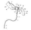
- FIG. 1shows a first embodiment; it is a side view of an endoscope device.
- a medical endoscopehas a tip constituting portion 4 provided at a distal end of a soft elongated inserted portion 2 via a curved portion 3 .
- the inserted portion 2has a manipulation portion 5 provided at a proximal end thereof and having a built-in actuator 6 for curving the curved portion 3 .
- the manipulation portion 5has a universal cable 7 connected thereto and having a connector 8 provided at its tip portion. Further, the manipulation portion 5 has a forceps hole 9 formed at a proximal end thereof.
- the inserted portion 2internally has an illuminating optical system, a signal line connected to a solid image pickup element in the tip constituting portion 4 , an angle wire, an air and water supply tube, a forceps channel, etc. (none of them shown).
- a control box 11is provided in a consultating room of a hospital at an elevated position, for example, on a ceiling 10 .
- the control box 11has a light source video unit 12 and an air and water supply and suction unit 13 .
- the light source video unit 12has a monitor 14 connected thereto and installed on a wall 15 or the like.
- An endoscope holder 16is fixed to a bottom portion of the control box 11 .
- the endoscope holder 16is comprised of an articulated arm 17 and an endoscope manipulation unit 18 .
- the control box 11has a rotating support portion 19 provided on its bottom portion and which can rotate around a vertical axis.
- the rotating support portion 19has a first arm 17 a of the articulated arm 17 rotatably pivotably supported thereon via a first joint portion 20 and having an electromagnetic clutch brake 21 .
- the first arm 17 ahas a second arm 17 b rotatably pivotably supported at a lower end thereof via a second joint portion 22 also having an electromagnetic clutch brake 21 . Further, a gravity balancer 24 is provided between the first arm 17 a of the articulated arm 17 and the rotating support portion 19 so that the articulated arm 17 will not lower inadvertently even when the electromagnetic clutch brake 21 is released.
- the second arm 17 bhas an endoscope holding portion 25 provided at a lower end thereof.
- the endoscope holding portion 25can rotatably hold the manipulation portion 5 around its axis with the inserted potion 2 of the endoscope 1 suspended downward.
- the endoscope holding portion 25has the endoscope manipulation unit 18 integrated therewith.
- the endoscope manipulation unit 18includes a grip 26 having a curving manipulation switch 27 , an air and water supply switch 28 a , a suction switch 28 b , and a manipulation switch 28 c.
- the inserted portion 2can be suspended downward.
- the endoscope 1is electrically and optically connected to the air and water supply and suction unit 13 and the light source video unit 12 .
- the operatorgrips the manipulation portion 5 with the left hand, while holding the inserted portion 2 in the right hand to insert it into a body cavity from the tip constituting portion 4 of the inserted portion 2 . Since, however, the endoscope 1 is held by the endoscope holder 16 , the operator does not need to hold the endoscope 1 and can insert the inserted potion 2 into the body cavity of a patient 29 simply by holding this portion 2 .
- the endoscope manipulation unit 18 in the endoscope holder 16when the operator grips the grip 26 to operate the manipulation switch 28 c to unlock the electromagnetic clutch brakes 21 , 23 , the first and second joint portions 20 , 22 of the articulated arm 17 can be rotatively moved.
- the articulated arm 17When the operator depresses the grip 26 , the articulated arm 17 is extended to lower the entire endoscope 1 , whereas when the operator pulls up the grip 26 , the articulated arm 17 is contracted to elevate the entire endoscope 1 .
- the entire endoscope 1can be pivoted around the rotating support section 19 so as to be directed in an arbitrary direction.
- the manipulation section 5 of the endoscope 1is rotatably held on the endoscope holding section 25 , so that the entire endoscope 1 can be rotated by gripping and twisting the inserted portion 2 .
- the curving manipulation switch 27can be operated to curve the curved portion 3
- the air and water supply switch 28 a and the suction switch 28 bcan be operated to feed or suck an air or water.
- a forcepscan be inserted through the forceps hole 9 to gather tissues or the like as required.
- the entire endoscope 1is held by the endoscope holder 16 and supported by the articulated arm 16 with the gravity balancer 24 , thereby eliminating the need to manually hold the endoscope 1 and requiring only a small amount of force for manipulations to ease the operator's fatigue.
- the operatorcan use both hands to operate the inserted portion 2 and the various switches, so that the manipulability of the endoscope can be improved.
- the endoscope holder 16 and the various cables and tubesare located at elevated positions, movement of the operator and nurses is prevented from being obstructed and the consultating room can be kept clean.
- FIG. 2shows a second embodiment.
- the control box 11is provided on a horizontal portion 31 of a frame 30
- a monitor 14is provided on a vertical portion 32 thereof, and the remaining part of this configuration is the same as in the first embodiment.
- This embodimenteliminates the needs for work for installing the control box on the ceiling and easily accommodates a change in installation site.
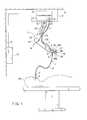
- FIG. 3shows a third embodiment.
- a control box 11 fixed to a ceiling 10has a housing device 33 in the form of a rotating drum provided inside and around which a flexible tube 34 is wound.
- the flexible tube 34has light guide fibers, a signal line, and an air and water supply and suction tube (not shown) installed inside.
- the flexible tube 34has a proximal end connected to a light source video unit 12 and an air and water supply and suction unit 13 and has a dismal end connected to a manipulation portion 5 of an endoscope.
- the endoscope 1is suspended via the flexible tube 34 , and the housing device 33 has a gravity balancer 35 for preventing the endoscope 1 from falling due to the weight thereof and urging the flexible tube 34 in a winding direction.
- FIG. 4shows a fourth embodiment.
- the same components as in the first embodimenthave the same reference numerals, and description thereof is omitted.
- a floor type control box 36 installed near a bed Bhas a light source video unit (not shown) and an air and water supply and suction unit (not shown) housed therein.
- a monitor 14is mounted and a strut 37 is provided in a fashion standing in a vertical direction.
- the strut 37has a stretchable arm 38 provided at an upper end portion thereof for rotative movement within a horizontal plane, and the stretchable arm 38 has an endoscope holder 39 provided at its tip portion.
- the endoscope holder 39holds a manipulation portion 5 of an endoscope 1 , from which an inserted portion 2 is suspended downward.
- the manipulation portion of the endoscopeis connected to a light source video unit and an air and water supply and suction unit both provided in the control box 36 , via light guide fibers, a signal line, and an air and water supply and suction tube (not shown) installed both inside the stretchable arm 38 and inside the strut 37 .
- the stretchable arm 38rotatively move around the strut 37 .
- the stretchable arm 38is contracted or stretched to enable the endoscope 1 to move to an arbitrary position. Accordingly, the manipulability of the endoscope 1 can be improved.
- the remaining part of the configuration and operationis the same as in the first embodiment, so that this embodiment provides effects similar to those of the first embodiment.
- FIG. 5shows a fifth embodiment.
- the same components as in the first and fourth embodimentshave the same reference numerals, and description thereof is omitted.
- a proximal end portion 40 of an endoscope 1is fixed to a tip portion of a stretchable arm 38 , and the endoscope 1 is suspended in such a manner that its inserted portion 2 extends downward.
- the proximal end portion 40has a built-in actuator (not shown) for curving a curved portion 3 of the inserted portion 2 .
- a bed Bincludes a terminal box 41 having a manipulation portion 43 that acts as manipulation means via a cord 42 .
- the manipulation portion 43has a curving manipulation switch 44 , an air and water supply switch, a suction switch, and a manipulation switch (the latter three switches are not shown) that all control the actuator.
- the operatorcan remote-control the endoscope 1 and peripheral equipment such as a light source video unit and an air and water supply and suction unit. Consequently, the manipulability of the endoscope can be improved.
- peripheral equipmentsuch as a light source video unit and an air and water supply and suction unit.
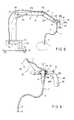
- FIG. 6shows a fourth embodiment; it is a vertical sectional side view of an endoscope holder.
- An elevated mounting portion 45such as a ceiling or a frame has a support ring 46 fixed thereto and on which a cylindrical control box 47 is rotatably supported.
- the support ring 46has a stator 48 fixed to the elevated mounting portion 45 in an axial portion thereof, and the stator 48 has a rotor 49 provided in its outer periphery and fixed to the control box 47 .
- the stator 48 and the rotor 49constitute a motor 50 .
- the control box 47has a light source video unit 51 , an air and water supply unit 52 , and a suction unit 53 provided inside and connected to a power supply via a looped cord 54 .
- the control box 47has a manipulation portion 5 of an endoscope 1 fixed to a bottom surface thereof in its axial portion, and the endoscope 1 is suspended from the control box 47 with an inserted portion 2 extending downward.
- the manipulation portion 5has a built-in actuator (not shown) for curving-a curved portion 3 of the inserted portion 2 , and also has switches such as a curving manipulation switch, an air and water supply switch, a suction switch, and a manipulation switch (none of them shown).
- a rotation torque T occurring when the inserted portion 2 is gripped and twistedis measured using a torque sensor 55 . If the measured value does not meet a preset threshold torque Tthre, that is, if ⁇ Tthre ⁇ T ⁇ Tthre is not met, then the rotor 49 can be rotated in a direction in which the torque decreases, by feedback-controlling the rotor 49 relative to the stator 48 by an amount of current proportional to T ⁇ Tthre. Consequently, the load torque occurring when the operator twists the endoscope 1 can be reduced to improve the manipulability of the endoscope.
- FIGS. 7A to 7 Dshow a seventh embodiment.
- the same components as in the first embodimenthave the same reference numerals, and description thereof is omitted.
- FIG. 7Ais a front view
- FIG. 7Bis a left side view
- FIG. 7Cis a right side view
- FIG. 7Dis a top view.
- a control box 59is provided under a seat portion 58 of a chair body 57 having casters 56 .
- the control box 59has a light source video unit and an air and water supply and suction unit (neither of them shown) provided inside.
- One 60 a of the armrest portions of the chair body 57has an endoscope holder 61 , and as in the fifth embodiment, the endoscope holder 61 holds a proximal end portion 40 of an endoscope 1 suspended with its inserted portion 2 extending downward.
- the other armrest portion 60 b of the chair body 57has an endoscope manipulation portion 62 and a small-sized display 63 .
- the chair body 57has a foot switch 64 that can elevate and lower the seat portion 58 and operate peripheral equipment.
- a backrest portion 65 of the chair body 57has a keyboard 66 for inputting data to the endoscope 1 .
- the operatorcan remote-control the endoscope 1 and peripheral equipment such as a light source video unit and an air and water supply and suction unit. Consequently, the manipulability of the endoscope can be improved.
- peripheral equipmentsuch as a light source video unit and an air and water supply and suction unit.
- FIG. 8shows an eighth embodiment.
- the same components as in the first embodimenthave the same reference numerals, and description thereof is omitted.
- a floor type frame 70has casters 71 for movement.
- the frame 70has a light source video unit 12 and an air and water supply and suction unit 13 housed inside.
- the frame 70has an endoscope holder 16 consisting of an articulated arm 17 , and an endoscope holding portion 25 of the endoscope holder 16 holds a manipulation portion 5 of the endoscope 1 .
- the remaining part of the configuration and operationis the same as in the first embodiment, so that this embodiment provides effects similar to those of the first embodiment.
- FIG. 9shows a ninth embodiment.
- An endoscope holder 16has an endoscope holding portion 25 rotatably provided at a tip portion thereof via bearings 72 for holding a manipulation portion 5 of an endoscope 1 .
- the endoscope 1is suspended from the endoscope holding portion with its inserted portion 2 extending downward.
- the manipulation portion 5is rotated integrally with the inserted portion 2 when the operator grips and twists the inserted portion 2 .
- the load torque occurring when the operator twists the endoscope 1can be reduced to improve the manipulability of the endoscope.
- FIG. 10shows a tenth embodiment.
- An endoscope holding portion 25 of an endoscope holder 16holds a manipulation portion 5 of an endoscope 1 suspended therefrom with an inserted portion 2 extending downward.
- a manipulation portion body 80 of an endoscope 1is divided into two, that is, a proximal-end side casing 81 and a tip side casing 82 that are coupled together by means of clamps 83 .
- the proximal-end side casing 81has a motor 85 inside which comprises an encoder 84 and which is linked with a first gear 87 via a speed reducer 86 .
- the tip side casing 82has a second gear 88 inside which meshes with the first gear 87 and which includes a rotating shaft 89 having a pulley 90 .
- the pulley 90has an angle wire 91 laid around it and penetrating the inserted portion 2 so as to connect to a tip curved block 92 of a curved portion 3 .
- a curving manipulation switch 27 provided on an endoscope holding portion 25is connected to a motor control unit 93 that obtains information from the encoder 84 to control the rotation of a motor 85 .
- an instructed value indicating a curving angle or a curving speedis transmitted from the curving manipulation switch 27 to the motor control unit 93 .
- the motor control unit 93transmits a drive signal to the motor 85 in accordance with the instructed value to operate the motor 85 , thereby rotating the pulley 90 via the first and second gears 87 , 88 .
- the rotation of the pulley 90pushes or pulls the angle wire 91 to curve the curved portion 3 .
- the encoder 84 provided in the motor 85can transmit rotation information on the motor 85 to the motor control unit 93 as encoder information to check whether or not the motor 85 is operating correctly in accordance with the instructed value. Accordingly, the curving manipulation switch 27 can be used to simply and accurately curve the curved portion 3 of the endoscope 1 , thereby improving the manipulability of the endoscope.
- the manipulation portion body 80can be separated into the proximal-end side casing 81 and the tip side casing 82 by unlocking the clamp 83 .
- the first and second gears 87 and 88are disengaged from each other to block the power of the motor 85 .
- the second gear 88can be manually rotated to curve or straighten the curved portion 3 , thereby improving safety.
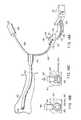
- FIGS. 11 and 12show an eleventh embodiment.
- FIG. 11is a perspective view of the overall endoscope device
- FIG. 12is a configuration diagram of the overall endoscope device.
- a medical endoscope 101has a tip-constituting portion 104 provided at a distal end of an elongate soft inserted portion 102 via a curved portion 103 .
- the inserted portion 102has a branched portion 105 at a proximal end thereof, and one of the branches from the branched portion 105 has the manipulation portion 107 connected thereto via a flexible cord 106 , while the other branch from the branched portion 105 has a connector 109 connected thereto via a universal cord 108 .
- the inserted portion 102has an illuminating optical system 110 , a signal like 112 connected to a solid image pickup element 111 of the tip constituting portion 104 , an angle wire 113 , an air and water supply tube 114 , a forceps channel 115 , etc. which are all installed inside the inserted portion 102 .
- the manipulation portion 107has an angle manipulation knob 116 acting as a curving manipulation portion, an air and water supply switch 117 a and a suction switch 117 b , and a treatment instrument insertion port 118 in communication with the forceps channel 115 .
- the manipulation portion 107has a rotating drum 119 provided inside and rotated by means of the angle manipulation knob 116 , and the angle wire 113 is laid around the rotating drum 119 .
- the curved portion 103can be curved by pushing and pulling the angle wire 113 .
- one set of the angle wire 113 and the rotating drum 119are shown, two sets are actually provided to enable the curved portion 103 to be curved both in a vertical and a lateral directions.
- a light video unit 120Separately from the endoscope 101 , a light video unit 120 , an air and water supply and suction unit 121 , and a monitor 122 are provided as external devices.
- the light source video unit 120has the illuminating optical system 110 and the signal line 112 of the solid image pickup element 111 removably connected thereto via the connector 109 .
- the air and water supply and suction unit 121has an air supply line 123 , a water supply line 124 , and a suction line 125 connected thereto and also has a signal line 126 connected thereto which is connected to the air and water supply switch 117 a and the suction switch 117 b.
- the air and water supply and suction unit 121has a first to a third solenoid valves 127 a to 127 c inside which are connected to the air supply line 123 , the water supply line 124 , and the suction line 125 and which are also connected to a first to a third pumps 128 a to 128 c respectively. Further, the air and water supply and suction unit 121 has a controller 129 provided inside for controlling the first to third solenoid valves 127 a to 127 c and the first to third pumps 128 a to 128 c in response to signals from the air and water supply switch 117 a and the suction switch 117 b.
- the operatorgrips the manipulation portion 107 with the left hand, while holding the inserted portion 102 in the right hand to insert it into a body cavity from the tip constituting portion 104 of the inserted portion 102 .
- the manipulation portion 107is connected via the flexible cord 106 branched from the branched portion 105 at a proximal end of the inserted portion 102 , only the weights of the manipulation portion 107 and flexible cord 106 are placed on the operator but not the weight of the inserted portion 102 .
- the manipulation portion 107includes only the angle manipulation portion 116 and its accessories, the air and water supply switch 117 a , and the suction switch 117 b and none of the illuminating optical system, air and water supply line, suction, line, and signal line that are relatively heavy pass through the manipulation portion 107 .
- the manipulation portion 107has such a small size and weight as to alleviate the fatigue of the operators left hand, thereby improving the manipulability of the endoscope.
- FIGS. 13 and 14show a twelfth embodiment.
- the same components as in the eleventh embodimenthave the same reference numerals, and description thereof is omitted.
- FIG. 13is a perspective view of the overall endoscope device
- FIG. 14is a configuration diagram of the overall endoscope device.
- One of the branches from a branched portion 105 provided at a proximal end of an inserted portion 102has a manipulation portion 107 connected thereto via a flexible cord 106
- the other branch from the branched portion 105has a connector 109 connected thereto via a universal cord 108 .
- the manipulation 107has a curving manipulation switch 130 acting as a curving manipulation portion, an air and water supply switch 117 a and a suction switch 117 b , and a treatment instrument insertion port 118 in communication with a forceps channel 115 .
- the connector 109can be attached and detached to and from a motor unit 131 having a motor 132 for forward and backward rotations and a rotating drum 133 rotated by the motor 132 .
- the rotating drum 133has an angle wire 113 laid around it and which can be pushed and pulled to curve the curved portion 103 .
- the motor unit 131is shown with one set of the angle wire 113 , the motor 132 , and the rotating drum 133 , two sets are actually provided to enable the curved portion 103 to be curved both in a vertical and a lateral directions.
- the motor 132is connected via a cord 134 to a motor control unit 135 operating as an external device and connected to the curving manipulation switch 130 of the manipulation switch 107 via a cord 136 .
- a light source video unit 120 operating as an external devicehas the illuminating optical system 110 and the signal line 112 of the solid image pickup element 111 removably connected thereto.
- the connector 109has an air supply line 123 , a water supply line 124 , and a suction line 125 connected thereto and to an air and water supply and suction unit 121 .
- the air and water supply and suction unit 121has a signal line 126 connected thereto and to the air and water supply switch 117 a and the suction switch 117 b.
- the manipulation portion 107is free from the angle manipulation portion 116 and its accessories and the motor unit 131 , which operates as an external device, can curve the curved portion 103 . Consequently, the size of the manipulation portion 107 can further be reduced to ease the operator's fatigue, thereby improving the manipulability of the endoscope.
- FIGS. 15A and 15Bshow a thirteenth embodiment.
- FIG. 15Ais a perspective view showing that a manipulation portion 140 is gripped with the left hand
- FIG. 15Bis a perspective view of the manipulation portion 140 .
- the manipulation portion 140is provided at a proximal end of a flexible cord 106 branched from a branched portion 105 as in the eleventh and twelfth embodiments.
- the manipulation portion 140is generally inverted-U-shaped and has an inverted-U-shaped recess 141 provided in a lower part thereof.
- the manipulation portion 140has a curve control switch 142 operating as a curving manipulation portion, an air and water supply switch 143 , and a suction switch 144 that are all provided on an outer right side surface thereof and has a forceps hole 146 provided on a proximal-end surface for inserting a forceps 145 therethrough.
- the operatorcan hold the manipulation portion 140 without the need to firmly grip it, whereby the operator's fatigue can be relieved to improve the manipulability of the endoscope.
- FIGS. 16A and 16Bshow a fourteenth embodiment.
- FIG. 16Ais a perspective view showing that a manipulation portion 147 is fixed to the left hand
- FIG. 16Bis a perspective view of the manipulation portion 147 .
- the manipulation portion 147is provided at a proximal end of a flexible cord 106 branched from a branched portion 105 as in the eleventh and twelfth embodiments.
- the manipulation portion 147has a proximal end portion formed into a general sphere and a tip portion 147 b formed into a flat shape integral with the proximal end portion 147 a , and the tip portion 147 b has a belt 148 that is fixed to the wrist of the operator's left hand L.
- the manipulation portion 147has a curve control switch 142 operating as a curving manipulation portion, an air and water supply switch 143 , and a suction switch 144 that are all provided on an outer right side surface of the proximal end portion 147 a and has a forceps hole 146 provided on a proximal-end surface for inserting a forceps 145 therethrough.
- the entire proximal end portion 147 a of the manipulation portion 140can be gripped by the palm. Then, the thumb, the ring finger, and the little finger can be used to operate the curve control switch 142 , the suction switch 144 , and the air and water supply switch 143 , respectively.
- the operatorcan hold the manipulation portion 147 without the need to firmly grip it.
- the operatorcan perform a series of operations without the need to release the manipulation portion 147 from the left hand L, whereby the manipulability of the endoscope can be improved.
- FIGS. 17A and 17Bshow a fifteenth embodiment.
- FIG. 17Ais a schematic configuration diagram of an endoscope and
- FIG. 17Bis a schematic configuration diagram showing that an inserted and a manipulation portions are separated from each other.
- An endoscope 150 according to this embodimentconsists of a manipulation portion 151 and an inserted portion 152 that can be attached and detached to and from the manipulation portion 151 , and the inserted portion 152 has a tip constituting portion 154 provided on a distal end side of thereof via a curved portion 153 .
- the curved portion 153has an inserted-portion-side angle wire 155 extending to the manipulation portion 151 , and the tip constituting portion 154 has a solid image pickup element 156 .
- the solid image pickup element 156has a signal line 157 extending to the manipulation portion 151 .
- the manipulation portion 151There is provided inside the manipulation portion 151 a motor 158 and a rotating drum 159 rotated by the motor 158 , and the rotating drum 159 has a manipulation-portion-side angle wire 160 laid around it.
- the manipulation-portion-side angle wire 155has opposite ends each connected to a corresponding one of the opposite ends of the manipulation-portion-side angle wire 160 by means of an angle wire connector 161 .
- the manipulation portion 151has the signal line 157 of the solid image pickup element 156 drawn thereinto, where the signal line 157 is connected to a signal connector 152 connected to a light source video unit (not shown).
- the signal line 157which is guided out from a proximal end of the inserted portion 152 and connected to a signal line connector 162 , has a larger length than the manipulation angle wire 155 , which is guided out from the proximal end of the inserted portion 152 and connected to the angle wire connector 161 .
- the curving operationis stopped by separating the inserted portion 152 from the manipulation portion 110 to disconnect the angle wire connector 161 . Since, however, the signal line 157 remains connected, the inserted portion 152 can be pulled out while checking the inside of the body cavity using a monitor (not shown).
- FIGS. 18A to 18 Cshow a sixteenth embodiment.
- the same components as in the twelfth embodimenthave the same reference numerals, and description thereof is omitted.
- a flexible cord 106 branched from an inserted portion 102 via a branched portion 105has an air supply line 123 , a water supply line 124 , and a suction line 125 inserted therethrough and connected to an air and water supply and suction unit 121 after penetrating a manipulation portion 107 .
- the manipulation portion 107has a through-hole 163 independently penetrated by the air supply line 123 , the water supply line 124 , and the suction line 125 .
- a support hole 164is formed in an upper part of the manipulation portion 107 in such a manner as to be opposed perpendicularly to the through-hole 163 , and the support hole 164 has a push button 165 inserted thereinto for free advancement and retreat.
- the push button 165usually remains pushed up by means of the elasticity of soft tubes constituting the lines as shown in FIG. 18B, but depressing the push button by the hand or finger enables the soft tubes to collapse to occlude the lines as shown in FIG. 18 C.
- the air or water supply or suctioncan be stopped by depressing the push button 165 to occlude the lines, thereby improving safety.
- FIG. 19shows a seventeenth embodiment.
- the same components as in the twelfth embodimenthave the same reference numerals, and description thereof is omitted.
- a flexible cord 106 branched from an inserted portion 102 via a branched portion 105includes a manipulation portion 107 having a first forceps hole 166 formed therein, and the branched portion 105 has a second forceps hole 167 formed therein.
- the operatortypically grips the manipulation portion 107 with the left hand and inserts a forceps through the first forceps hole 166 to gather tissues as required, and an assistant such as a nurse often stands between the manipulation portion 107 and the inserted portion 102 to assist the operator in manipulation.
- the assistantcan insert a forceps 168 through the second forceps hole 167 , which is provided in the branched portion 105 . Consequently, the operator and the assistant are prevented from coming in contact with each other, whereby the manipulability of the endoscope can be improved.
- FIG. 20is a schematic configuration diagram showing a configuration of a motor-operated curved endoscope.
- An electronic soft endoscopehas a manipulation portion 202 connected to an inserted portion 201 thereof on its side closer to the operator than to the patient.
- the inserted portion 201is comprised of an elongate flexible tube portion 211 , a curved tube portion 212 connected to a tip of the flexible tube portion 211 , and a hard tip portion 213 connected to a tip of the curved tube portion 212 .
- the tip portion 213has a solid image pickup element 214 such as a CCD and other devices provided therein as shown in FIG. 21 .
- the flexible tube portion 211is constructed by fitting a braid tube 216 on a spiral tube 215 and covering the braid tube 216 with a casing 217 as shown in FIG. 21 .
- the spiral tube 215is formed into a cylinder by winding a band-shaped metallic plate in the form of a spiral
- the braid tube 216is formed into a cylinder by braiding a large number of metallic wires.
- the curved tube portion 212has a plurality of curved blocks 221 arranged in a longitudinal axial direction of the inserted portion 201 ; the curved tube portion 212 is configured by using rivet-like shaft pins 222 to rotatably connecting the adjacent curved blocks 221 together to construct an entirely bendable tubular curved tube core 223 , fitting a cylindrical braid on the curved tube core 223 in an outer periphery thereof, and covering an outer periphery of the braid 224 with a casing 225 .
- the curving direction of the individual curved blocks 221depends on positions at which the shaft pins 222 are provided.
- the shaft pins 222are arranged alternately or as appropriate in a lateral or vertical direction so as to enable the curved tube core 223 to be entirely curved in the lateral or vertical direction.
- the curved tube core 223constitutes a curving mechanism 236 that is curved in a traction direction by means of an angle wire 235 , which will be described below.
- the curved blocks 221 other than the leading and trailing ones 221each have ring-shaped wire guides 237 attached by means of brazing or the like to an inner surface thereof at positions corresponding to the angle wires 235 , which are arranged in an upper and a lower positions as well as a left and a right positions, so that the angle wires 235 can be individually inserted through these curved blocks 221 and guided for free advancement and retreat.
- the leading curved block or the body member of the tip portion 213has tips of the angle wires 235 each fixed thereto by means of brazing or the like.
- the curved tube portion 212can be curved in the direction of the selected angle wire 235 .
- the flexible tube portion 211 and curved tube portion 212 of the inserted portion 201are connected together using a metallic connection tube 241 .
- the spiral tube 215 and braid tube 216 of the flexible tube portion 211have a laminated tip portion fitted in a rear end portion of the connection tube 241 and fixed thereto by means of brazing or the like.
- a rear end portion of the trailing curved block 221 in the curved tube core 223 of the curved tube portion 212is fitted on an outer periphery of a tip portion of the connection tube 241 and fixed by means of brazing or screwing.
- Rear end portions of the braid 224 and casing 225 of the curved tube portion 212pass beyond the trailing curved block 221 to the outer peripheral portion of the connection tube 241 , where these portions are fitted and fixed by means of brazing or the like.
- the casing 217 of the flexible tube portion 211 and the casing 225 of the curved tube portion 212are butted on each other, and a yarn 242 is tightly wound and tightened around the butted end portions thereof on their outer periphery.
- an adhesive 243is applied to an outer periphery of the yarn-wound portion to seal the butted portion in a liquid-tight manner.
- Such a connection portion between the flexible tube portion 211 and the curved tube portion 212typically constitutes a relatively hard area.
- the guide sheathconsists, for example, of a coil sheath 245 formed by tightly winding a coil wire of stainless steel (SUS) in the form of a coil, and each coil sheath 245 has a corresponding one of the angle wires 235 individually inserted therethrough.
- a tip of the coil sheath 245is brazed and fixedly attached to an inner surface of the connection tube 241 .
- a rear end side of the coil sheath 245is located in the flexible tube portion 211 of the inserted portion 201 and guided to the manipulation portion 202 together with other built-in components.
- the manipulation portion 202internally has a pulley 246 a around which is wound a wire having each of the upper and lower angle wires 235 connected to a corresponding one of the opposite ends thereof, and a pulley 246 b around which is wound a wire having each of the left and right angle wires 235 connected to a corresponding one of the opposite ends thereof.
- the pulleys 246 a , 246 bare rotated by electric motors 247 a , 247 b in a forward and a backward directions.
- the electric motors 247 a , 247 bare driven by a motor drive portion 249 controlled by a control device 248 .
- An actuatormakes the electric motors 247 a , 247 b rotate the pulleys 246 a , 246 b and curves the curved tube portion 212 via the angle wire 235 .
- the operating position of the actuatoris detected by actuator position detection means.
- the actuator position detection means in this embodimentis comprised of rotary encoders 251 a , 251 b mounted on shaft positions of the electric motors 247 a , 247 b so as to detect the curving angle of the curving mechanism 236 based on output signals from the rotary encoders 251 a , 251 b .
- the control device 248is adapted to control the amount of curving manipulation performed by the actuator so as to curve the curved tube portion 212 up to a predetermined curving angle based on a position detection signal from the actuator position detection means.
- the manipulation portion 202has a joy stick 252 operating as a curving manipulation portion.
- the joy stick 252is used to specify a vertical and a lateral curving directions and to indicate the amount of curving manipulation.
- a vertical-direction joy stick motor 253 a and a lateral-direction joy stick 253 bare rotated, and their rotating angles, that is, the amounts of curving manipulation are detected by rotary encoders 254 a , 254 b .
- Detection signals from the rotary encoders 254 a , 254 bare input to the control device 248 via an input driver 255 .
- the inserted portion 201has a tension sensor 256 such as a distortion sensor fixed to a tip portion 213 thereof in a fashion corresponding to each angle wire 235 , and the tension sensor 256 has a tip portion of the angle wire 235 connected thereto to detect the tension of the angle wire 235 .
- a signal line 257 from the tension sensor 256is connected to the control device 248 through the inserted portion 201 via a tension sense amplifier 258 and an A/D converter 259 both provided in the manipulation portion 2 .
- a displacement sensor 260such as an electromagnetic induction sensor or a laser displacement sensor is fixed to the inside of the connection tube 241 between the tip portion of the flexible tube portion 211 and the rear end portion of the curved tube portion 212 to detect the displacement of the angle wire 235 in its axial direction.
- the displacement sensor 260is integrated into a coil sheath 245 through which the angle wire 235 is inserted and guided.
- Signal lines 262are guided out from opposite ends of a sensor coil 261 of the displacement sensor 260 and connected to the control device 248 through the inserted portion 201 via a displacement sense amplifier 263 and an A/D converter 264 both provided in the manipulation portion 202 .
- the joy stick 252When the joy stick 252 is rotatively moved, for example, in a vertical direction of the operator, the joy stick motor 253 a rotates and its rotation is detected by the encoder 254 a , which then inputs an instruction to the control device 248 via the input driver 255 . Then, the electric motor 247 a rotates the pulley 246 a in a rotating direction of the motor to draw the angle wire 235 so as to curve the curved tube portion 212 in a desired direction. At this point, the electric motor 247 a is servo-controlled.
- the tension measured by the tension sensor 256increases linearly with the displacement measured by the displacement sensor 260 as indicated by a curve A. If, however, the relationship between the tension measured by the tension sensor 256 and the displacement measured by the displacement sensor 260 is determined at a point B during actual curving of the curved tube portion 212 or during a medical treatment, then an external force corresponding to a difference in tension C relative to the curve A is being applied to the curved tube portion 212 .
- the displacement of the angle wire 235is measured by the displacement sensor 260 , and results of the measurement are input to the control device 248 via the displacement sense amplifier 263 and the A/D converter 264 .
- the tension sensor 256measures this tension and results of the measurement are input to the control device 248 via the tension sense amplifier 258 and the A/D converter 259 .
- the control device 248calculates the difference in tension C relative to the curve A and operates the input driver 255 so as to feed back to the joy stick 252 an amount of force corresponding to the value C. Accordingly, the operator manipulating the joy stick 252 senses in the hand an external force applied to the tip portion 213 of the inserted portion 201 .
- the displacement sensor 260installed in the inserted portion 201 to measure the displacement of the angle wire
- reliable controlcan be provided so as to avoid the angle down phenomenon despite deformation of the inserted portion 201 .
- the tension sensor 256installed to measure the tension of the angle wire 235 , when the curved tube portion 212 is curved and the tip portion 213 then abuts on the body cavity wall b or the like to apply an external force to the curved tip portion 212 , the tension is measured by the tension sensor 256 .
- joy stick 252can be used for manipulations such as returning the curved tube portion 212 to a straight form and changing the curving direction, thereby improving the manipulability of the endoscope.
- the present inventionis not limited to the above configuration in which the tension sensor 256 measures the tension of the angle wire 235 so that the control device 248 can calculate the difference in tension C and feeds back to the joy stick 252 a amount of force corresponding to the difference C.
- the operatormay be notified of an external force applied to the tip portion 213 by means of lighting of an alarm lamp or actuation of an alarm buzzer based on a detection signal from the tension sensor 256 .
- the present inventionis not limited to medical endoscopes but is applicable to industrial ones.
- the operatormay continue moving the inserted portion forward without noticing that the tip portion is abutting the pipe wall, thereby cutting the angle wire or damaging the curved tube portion or the tip portion of the curved tube portion. This problem can be solved by providing the tension sensor.
Landscapes
- Health & Medical Sciences (AREA)
- Life Sciences & Earth Sciences (AREA)
- Surgery (AREA)
- General Health & Medical Sciences (AREA)
- Public Health (AREA)
- Veterinary Medicine (AREA)
- Pathology (AREA)
- Nuclear Medicine, Radiotherapy & Molecular Imaging (AREA)
- Animal Behavior & Ethology (AREA)
- Engineering & Computer Science (AREA)
- Biomedical Technology (AREA)
- Heart & Thoracic Surgery (AREA)
- Medical Informatics (AREA)
- Molecular Biology (AREA)
- Biophysics (AREA)
- Physics & Mathematics (AREA)
- Radiology & Medical Imaging (AREA)
- Optics & Photonics (AREA)
- Oral & Maxillofacial Surgery (AREA)
- Endoscopes (AREA)
- Instruments For Viewing The Inside Of Hollow Bodies (AREA)
Abstract
Description
Claims (19)
Applications Claiming Priority (6)
| Application Number | Priority Date | Filing Date | Title |
|---|---|---|---|
| JP11-093796 | 1999-03-31 | ||
| JP09379499AJP3549434B2 (en) | 1999-03-31 | 1999-03-31 | Electric curved endoscope |
| JP09379699AJP3549435B2 (en) | 1999-03-31 | 1999-03-31 | Endoscope device |
| JP11-093794 | 1999-03-31 | ||
| JP11093795AJP2000279367A (en) | 1999-03-31 | 1999-03-31 | Endoscope device |
| JP11-093795 | 1999-03-31 |
Publications (1)
| Publication Number | Publication Date |
|---|---|
| US6569084B1true US6569084B1 (en) | 2003-05-27 |
Family
ID=27307392
Family Applications (1)
| Application Number | Title | Priority Date | Filing Date |
|---|---|---|---|
| US09/536,403Expired - LifetimeUS6569084B1 (en) | 1999-03-31 | 2000-03-28 | Endoscope holder and endoscope device |
Country Status (1)
| Country | Link |
|---|---|
| US (1) | US6569084B1 (en) |
Cited By (131)
| Publication number | Priority date | Publication date | Assignee | Title |
|---|---|---|---|---|
| US20040024387A1 (en)* | 2002-04-15 | 2004-02-05 | Shaharam Payandeh | Devices for positioning implements about fixed points |
| US20040052630A1 (en)* | 2002-09-04 | 2004-03-18 | Fanuc Ltd. | Cable laying structure for robot |
| US20040054254A1 (en)* | 2002-09-13 | 2004-03-18 | Kiyoshi Miyake | Endoscope apparatus |
| US20040073083A1 (en)* | 2002-09-30 | 2004-04-15 | Olympus Optical Co., Ltd. | Electric bending endoscope |
| US20040125437A1 (en)* | 2002-09-17 | 2004-07-01 | Martin Schmidt | Operating-microscope system |
| US20040133075A1 (en)* | 2002-08-06 | 2004-07-08 | Nobuyuki Motoki | Endoscope apparatus |
| US20040172012A1 (en)* | 2003-01-15 | 2004-09-02 | Olympus Corporation | Medical instrument holding device |
| US20040176751A1 (en)* | 2002-08-14 | 2004-09-09 | Endovia Medical, Inc. | Robotic medical instrument system |
| US20040193146A1 (en)* | 2001-02-15 | 2004-09-30 | Endo Via Medical, Inc. | Robotically controlled surgical instruments |
| US20040210106A1 (en)* | 2003-03-31 | 2004-10-21 | Olympus Corporation | Stereoscopic observation system |
| US20050119522A1 (en)* | 2003-11-28 | 2005-06-02 | Olympus Corporation | Endoscope treatment tool insertion-extraction system |
| US20050182292A1 (en)* | 2004-01-16 | 2005-08-18 | Olympus Corporation | Endoscopic surgical instrument |
| US20050200324A1 (en)* | 1999-04-07 | 2005-09-15 | Intuitive Surgical Inc. | Non-force reflecting method for providing tool force information to a user of a telesurgical system |
| US20050216033A1 (en)* | 2001-02-15 | 2005-09-29 | Endo Via Medical Inc. | Robotically controlled medical instrument with a flexible section |
| US20060020163A1 (en)* | 2004-07-26 | 2006-01-26 | Ng Raymond C | Medical examination apparatus |
| US20060106280A1 (en)* | 2004-05-14 | 2006-05-18 | Surti Vihar C | Scope dock |
| US7104512B2 (en)* | 2002-03-08 | 2006-09-12 | Wolfvision Gmbh | Articulated arm especially for a device for optically capturing objects |
| US20060235268A1 (en)* | 2005-04-13 | 2006-10-19 | Innerspace Corporation | Medical device storage apparatus |
| US20060287576A1 (en)* | 2004-03-02 | 2006-12-21 | Olympus Corporation | Endoscope |
| WO2007029380A1 (en) | 2005-09-02 | 2007-03-15 | Olympus Medical Systems Corp. | Medical device |
| US20070066866A1 (en)* | 2004-04-21 | 2007-03-22 | Toshiaki Noguchi | Medical bed |
| USD539423S1 (en)* | 2005-06-20 | 2007-03-27 | Innerspace Corporation | Medical instrument holder |
| US20070073102A1 (en)* | 2005-09-27 | 2007-03-29 | Kiyotaka Matsuno | Endoscope apparatus |
| US20070142702A1 (en)* | 2005-11-30 | 2007-06-21 | Wilson-Cook Medical Inc. D/B/A Cook Endoscopy | Scope dock with fluid reservoir |
| USD549334S1 (en)* | 2006-09-11 | 2007-08-21 | Stryker Gi, Ltd. | Stand |
| US20080071291A1 (en)* | 2006-06-13 | 2008-03-20 | Intuitive Surgical, Inc. | Minimally invasive surgical system |
| US20080132755A1 (en)* | 2005-09-06 | 2008-06-05 | Olympus Medical Systems Corp. | Medical device |
| US20080154089A1 (en)* | 2005-03-14 | 2008-06-26 | Noriaki Kanazawa | Electronic Bending Endoscope Device and Endoscope Supporting Device |
| US20080171909A1 (en)* | 2004-02-27 | 2008-07-17 | Olympus Corporation | Endoscope and endoscopic system |
| US20080194909A1 (en)* | 2007-02-13 | 2008-08-14 | Brown Stuart I | Holding device for medical purposes |
| US20080208002A1 (en)* | 2007-02-28 | 2008-08-28 | Olympus Corporation | Endoscope |
| US20080221591A1 (en)* | 2007-02-20 | 2008-09-11 | Board Of Regents Of The University Of Nebraska | Methods, systems, and devices for surgical visualization and device manipulation |
| WO2009000854A1 (en)* | 2007-06-25 | 2008-12-31 | Tahar Benhidjeb | Surgical instrument |
| US20090082621A1 (en)* | 2005-04-11 | 2009-03-26 | Yuichi Ikeda | Electric Bending Endoscope Apparatus |
| US20090209888A1 (en)* | 2008-02-18 | 2009-08-20 | Seyed Hessam Khatami | Spine Wheel |
| US20090287055A1 (en)* | 2008-05-14 | 2009-11-19 | Olympus Medical Systems Corp. | Electric bending operation device and medical treatment system including electric bending operation device |
| US20100030023A1 (en)* | 2008-08-04 | 2010-02-04 | Olympus Medical Systems Corp. | Active drive type medical apparatus and drive control method |
| US7713190B2 (en) | 1998-02-24 | 2010-05-11 | Hansen Medical, Inc. | Flexible instrument |
| US7727185B2 (en) | 2001-02-15 | 2010-06-01 | Hansen Medical, Inc. | Coaxial catheter system |
| CN101261361B (en)* | 2004-02-27 | 2010-06-16 | 奥林巴斯株式会社 | Endoscope and endoscopic system |
| US20100228191A1 (en)* | 2009-03-05 | 2010-09-09 | Hansen Medical, Inc. | Lockable support assembly and method |
| US20100249501A1 (en)* | 2007-03-27 | 2010-09-30 | Kiyotaka Matsuno | Endoscope apparatus |
| DE202009009341U1 (en)* | 2009-07-07 | 2010-11-18 | Neumann, Martin, Dr. | Endoscopy workplace |
| US20110015648A1 (en)* | 2009-07-16 | 2011-01-20 | Hansen Medical, Inc. | Endoscopic robotic catheter system |
| US20110201886A1 (en)* | 2008-02-07 | 2011-08-18 | The Trustees Of Columbia University In The City Of New York | Remote endoscope handle manipulation |
| US8007511B2 (en) | 2003-06-06 | 2011-08-30 | Hansen Medical, Inc. | Surgical instrument design |
| US20110213383A1 (en)* | 2002-09-09 | 2011-09-01 | Hansen Medical, Inc. | Surgical instrument coupling mechanism |
| US20120004503A1 (en)* | 2009-03-19 | 2012-01-05 | Olympus Corporation | Treatment endoscope |
| US8114097B2 (en) | 1998-02-24 | 2012-02-14 | Hansen Medical, Inc. | Flexible instrument |
| US20120065470A1 (en)* | 2010-09-14 | 2012-03-15 | The Johns Hopkins University | Robotic system to augment endoscopes |
| US20120130159A1 (en)* | 2010-11-24 | 2012-05-24 | Omid Abri | Holding system for medical instruments |
| US8414505B1 (en) | 2001-02-15 | 2013-04-09 | Hansen Medical, Inc. | Catheter driver system |
| US20130197540A1 (en)* | 2003-05-21 | 2013-08-01 | The Johns Hopkins University | Devices, systems and methods for minimally invasive surgery of the throat and other portions of mammalian body |
| US8721530B2 (en) | 2000-04-03 | 2014-05-13 | Intuitive Surgical Operations, Inc. | Tendon-driven endoscope and methods of use |
| US20140175208A1 (en)* | 2012-12-20 | 2014-06-26 | Solar Turbines Incorporated | Portable tube coiler |
| US8827894B2 (en) | 2000-04-03 | 2014-09-09 | Intuitive Surgical Operations, Inc. | Steerable endoscope and improved method of insertion |
| US8888688B2 (en) | 2000-04-03 | 2014-11-18 | Intuitive Surgical Operations, Inc. | Connector device for a controllable instrument |
| US8926502B2 (en) | 2011-03-07 | 2015-01-06 | Endochoice, Inc. | Multi camera endoscope having a side service channel |
| EP2848189A1 (en) | 2013-09-17 | 2015-03-18 | Karl Storz GmbH & Co. KG | Endoscopic system |
| US9101287B2 (en) | 2011-03-07 | 2015-08-11 | Endochoice Innovation Center Ltd. | Multi camera endoscope assembly having multiple working channels |
| US9101268B2 (en) | 2009-06-18 | 2015-08-11 | Endochoice Innovation Center Ltd. | Multi-camera endoscope |
| US9101266B2 (en) | 2011-02-07 | 2015-08-11 | Endochoice Innovation Center Ltd. | Multi-element cover for a multi-camera endoscope |
| US9138129B2 (en) | 2007-06-13 | 2015-09-22 | Intuitive Surgical Operations, Inc. | Method and system for moving a plurality of articulated instruments in tandem back towards an entry guide |
| US20150359419A1 (en)* | 2013-02-21 | 2015-12-17 | Olympus Corporation | Object insertion system |
| US20160007832A1 (en)* | 2013-06-19 | 2016-01-14 | Olympus Corporation | Endoscope |
| US9265405B2 (en) | 2012-07-02 | 2016-02-23 | Olympus Corporation | Endoscope system |
| US9314147B2 (en) | 2011-12-13 | 2016-04-19 | Endochoice Innovation Center Ltd. | Rotatable connector for an endoscope |
| US9320419B2 (en) | 2010-12-09 | 2016-04-26 | Endochoice Innovation Center Ltd. | Fluid channeling component of a multi-camera endoscope |
| US9333042B2 (en) | 2007-06-13 | 2016-05-10 | Intuitive Surgical Operations, Inc. | Medical robotic system with coupled control modes |
| US9402533B2 (en) | 2011-03-07 | 2016-08-02 | Endochoice Innovation Center Ltd. | Endoscope circuit board assembly |
| US20160242631A1 (en)* | 2009-04-23 | 2016-08-25 | M.S.T. Medical Surgery Technologies Ltd | Two-part endoscope surgical device |
| US9427282B2 (en) | 2000-04-03 | 2016-08-30 | Intuitive Surgical Operations, Inc. | Apparatus and methods for facilitating treatment of tissue via improved delivery of energy based and non-energy based modalities |
| US9469034B2 (en) | 2007-06-13 | 2016-10-18 | Intuitive Surgical Operations, Inc. | Method and system for switching modes of a robotic system |
| US9492063B2 (en) | 2009-06-18 | 2016-11-15 | Endochoice Innovation Center Ltd. | Multi-viewing element endoscope |
| US9492927B2 (en) | 2009-08-15 | 2016-11-15 | Intuitive Surgical Operations, Inc. | Application of force feedback on an input device to urge its operator to command an articulated instrument to a preferred pose |
| US9516996B2 (en) | 2008-06-27 | 2016-12-13 | Intuitive Surgical Operations, Inc. | Medical robotic system providing computer generated auxiliary views of a camera instrument for controlling the position and orienting of its tip |
| US9526583B2 (en) | 2005-12-30 | 2016-12-27 | Intuitive Surgical Operations, Inc. | Robotic surgery system including position sensors using fiber Bragg gratings |
| US9554692B2 (en) | 2009-06-18 | 2017-01-31 | EndoChoice Innovation Ctr. Ltd. | Multi-camera endoscope |
| US9560953B2 (en) | 2010-09-20 | 2017-02-07 | Endochoice, Inc. | Operational interface in a multi-viewing element endoscope |
| US9560954B2 (en) | 2012-07-24 | 2017-02-07 | Endochoice, Inc. | Connector for use with endoscope |
| US20170052358A1 (en)* | 2014-06-20 | 2017-02-23 | Sony Olympus Medical Solutions Inc. | Medical observation apparatus and medical observation system |
| US9622826B2 (en) | 2010-02-12 | 2017-04-18 | Intuitive Surgical Operations, Inc. | Medical robotic system providing sensory feedback indicating a difference between a commanded state and a preferred pose of an articulated instrument |
| US9642513B2 (en) | 2009-06-18 | 2017-05-09 | Endochoice Inc. | Compact multi-viewing element endoscope system |
| US9655502B2 (en) | 2011-12-13 | 2017-05-23 | EndoChoice Innovation Center, Ltd. | Removable tip endoscope |
| US9706907B2 (en) | 2008-02-07 | 2017-07-18 | Institute For Cancer Research | Remote endoscope handle manipulation |
| US9706903B2 (en) | 2009-06-18 | 2017-07-18 | Endochoice, Inc. | Multiple viewing elements endoscope system with modular imaging units |
| US9713417B2 (en) | 2009-06-18 | 2017-07-25 | Endochoice, Inc. | Image capture assembly for use in a multi-viewing elements endoscope |
| US9717563B2 (en) | 2008-06-27 | 2017-08-01 | Intuitive Surgical Operations, Inc. | Medical robotic system providing an auxilary view including range of motion limitations for articulatable instruments extending out of a distal end of an entry guide |
| US9718190B2 (en) | 2006-06-29 | 2017-08-01 | Intuitive Surgical Operations, Inc. | Tool position and identification indicator displayed in a boundary area of a computer display screen |
| US9757149B2 (en) | 2006-06-13 | 2017-09-12 | Intuitive Surgical Operations, Inc. | Surgical system entry guide |
| US9789608B2 (en) | 2006-06-29 | 2017-10-17 | Intuitive Surgical Operations, Inc. | Synthetic representation of a surgical robot |
| US9788909B2 (en) | 2006-06-29 | 2017-10-17 | Intuitive Surgical Operations, Inc | Synthetic representation of a surgical instrument |
| US20170296040A1 (en)* | 2014-09-30 | 2017-10-19 | Riverfield Inc. | Adapter component set |
| US9808140B2 (en) | 2000-04-03 | 2017-11-07 | Intuitive Surgical Operations, Inc. | Steerable segmented endoscope and method of insertion |
| US9814374B2 (en) | 2010-12-09 | 2017-11-14 | Endochoice Innovation Center Ltd. | Flexible electronic circuit board for a multi-camera endoscope |
| US9872609B2 (en) | 2009-06-18 | 2018-01-23 | Endochoice Innovation Center Ltd. | Multi-camera endoscope |
| US9901244B2 (en) | 2009-06-18 | 2018-02-27 | Endochoice, Inc. | Circuit board assembly of a multiple viewing elements endoscope |
| US20180071049A1 (en)* | 2015-03-27 | 2018-03-15 | Medineering Gmbh | Method and apparatus for controlling a surgical mechatronic assistance system by means of a holding arm for medical purposes |
| US9956044B2 (en) | 2009-08-15 | 2018-05-01 | Intuitive Surgical Operations, Inc. | Controller assisted reconfiguration of an articulated instrument during movement into and out of an entry guide |
| US9962066B2 (en) | 2005-12-30 | 2018-05-08 | Intuitive Surgical Operations, Inc. | Methods and apparatus to shape flexible entry guides for minimally invasive surgery |
| US9986899B2 (en) | 2013-03-28 | 2018-06-05 | Endochoice, Inc. | Manifold for a multiple viewing elements endoscope |
| US9993142B2 (en) | 2013-03-28 | 2018-06-12 | Endochoice, Inc. | Fluid distribution device for a multiple viewing elements endoscope |
| US10008017B2 (en) | 2006-06-29 | 2018-06-26 | Intuitive Surgical Operations, Inc. | Rendering tool information as graphic overlays on displayed images of tools |
| US20180259122A1 (en)* | 2017-03-07 | 2018-09-13 | James Dulin REAVILL | Medical multi-link boom |
| US10080486B2 (en) | 2010-09-20 | 2018-09-25 | Endochoice Innovation Center Ltd. | Multi-camera endoscope having fluid channels |
| US10165929B2 (en) | 2009-06-18 | 2019-01-01 | Endochoice, Inc. | Compact multi-viewing element endoscope system |
| US10203493B2 (en) | 2010-10-28 | 2019-02-12 | Endochoice Innovation Center Ltd. | Optical systems for multi-sensor endoscopes |
| US20190067891A1 (en)* | 2017-08-28 | 2019-02-28 | Scholly Fiberoptic Gmbh | Endoscope having a rotatable electric connecting element |
| US10258425B2 (en) | 2008-06-27 | 2019-04-16 | Intuitive Surgical Operations, Inc. | Medical robotic system providing an auxiliary view of articulatable instruments extending out of a distal end of an entry guide |
| US10499794B2 (en) | 2013-05-09 | 2019-12-10 | Endochoice, Inc. | Operational interface in a multi-viewing element endoscope |
| US10507066B2 (en) | 2013-02-15 | 2019-12-17 | Intuitive Surgical Operations, Inc. | Providing information of tools by filtering image areas adjacent to or on displayed images of the tools |
| WO2020130977A1 (en) | 2018-12-18 | 2020-06-25 | İzmi̇r Yüksek Teknoloji̇ Ensti̇tüsü | Endoscope/laparoscope easy attach-detach mechanism |
| EP3735890A1 (en) | 2015-09-17 | 2020-11-11 | Endomaster Pte Ltd | Improved flexible robotic endoscopy system |
| CN112315408A (en)* | 2019-08-05 | 2021-02-05 | 卡尔史托斯两合公司 | Medical equipment |
| US20210100429A1 (en)* | 2019-10-07 | 2021-04-08 | Boston Scientific Scimed, Inc. | Endoscopic device with interchangeable shaft |
| WO2021094673A1 (en)* | 2019-11-15 | 2021-05-20 | Robocath | Elongated, flexible articulated arm for holding a medical instrument, having a handle and a locking and unlocking actuator |
| US20210298574A1 (en)* | 2020-03-30 | 2021-09-30 | Medicaroid Corporation | Endoscope adaptor |
| US20210307592A1 (en)* | 2020-03-30 | 2021-10-07 | Medicaroid Corporation | Endoscope adaptor, robotic surgical system, method of adjusting rotational position using endoscope adaptor |
| US11213356B2 (en) | 2010-09-17 | 2022-01-04 | Auris Health, Inc. | Systems and methods for positioning an elongate member inside a body |
| US11278190B2 (en) | 2009-06-18 | 2022-03-22 | Endochoice, Inc. | Multi-viewing element endoscope |
| US11547275B2 (en) | 2009-06-18 | 2023-01-10 | Endochoice, Inc. | Compact multi-viewing element endoscope system |
| US20230039326A1 (en)* | 2019-11-28 | 2023-02-09 | Easyendo Surgical, Inc. | Stone removing apparatus and stone size measuring method |
| US11701192B2 (en) | 2016-08-26 | 2023-07-18 | Auris Health, Inc. | Steerable catheter with shaft load distributions |
| US11864734B2 (en) | 2009-06-18 | 2024-01-09 | Endochoice, Inc. | Multi-camera endoscope |
| US11889986B2 (en) | 2010-12-09 | 2024-02-06 | Endochoice, Inc. | Flexible electronic circuit board for a multi-camera endoscope |
| US12137873B2 (en) | 2009-06-18 | 2024-11-12 | Endochoice, Inc. | Compact multi-viewing element endoscope system |
| US12204087B2 (en) | 2010-10-28 | 2025-01-21 | Endochoice, Inc. | Optical systems for multi-sensor endoscopes |
| US12220105B2 (en) | 2010-06-16 | 2025-02-11 | Endochoice, Inc. | Circuit board assembly of a multiple viewing elements endoscope |
| US12239396B2 (en) | 2008-06-27 | 2025-03-04 | Intuitive Surgical Operations, Inc. | Medical robotic system providing an auxiliary view including range of motion limitations for articulatable instruments extending out of a distal end of an entry guide |
| US12266040B2 (en) | 2009-03-31 | 2025-04-01 | Intuitive Surgical Operations, Inc. | Rendering tool information as graphic overlays on displayed images of tools |
| US12357400B2 (en) | 2006-06-29 | 2025-07-15 | Intuitive Surgical Operations, Inc. | Synthetic representation of a surgical robot |
Citations (13)
| Publication number | Priority date | Publication date | Assignee | Title |
|---|---|---|---|---|
| US3566872A (en)* | 1968-11-21 | 1971-03-02 | Moeller J D Optik | Microsurgical operating unit |
| US4617915A (en)* | 1984-03-27 | 1986-10-21 | Fuji Photo Optical Co., Ltd. | Construction of manual control section of endoscope |
| JPS63194659A (en) | 1987-02-06 | 1988-08-11 | オリンパス光学工業株式会社 | Chair for endoscope apparatus |
| US4854301A (en) | 1986-11-13 | 1989-08-08 | Olympus Optical Co., Ltd. | Endoscope apparatus having a chair with a switch |
| US5159446A (en)* | 1991-06-21 | 1992-10-27 | Olympus Optical Co., Ltd. | Electronic endoscope system provided with a separate camera controlling unit and motor controlling unit |
| US5184601A (en)* | 1991-08-05 | 1993-02-09 | Putman John M | Endoscope stabilizer |
| US5243967A (en)* | 1991-03-26 | 1993-09-14 | Olympus Optical Co., Ltd. | Endoscope system providing mutual operative communication between the drive control means and the video signal control means |
| US5259365A (en)* | 1989-07-26 | 1993-11-09 | Olympus Optical Co., Ltd. | Endoscope examination apparatus |
| JPH0630891A (en) | 1992-07-16 | 1994-02-08 | Toshiba Medical Eng Co Ltd | Endoscope |
| US5490652A (en)* | 1993-03-04 | 1996-02-13 | Kreuzer Gmbh + Co. Ohg | Overhead support |
| US5531664A (en)* | 1990-12-26 | 1996-07-02 | Olympus Optical Co., Ltd. | Bending actuator having a coil sheath with a fixed distal end and a free proximal end |
| US5876325A (en)* | 1993-11-02 | 1999-03-02 | Olympus Optical Co., Ltd. | Surgical manipulation system |
| US6102850A (en)* | 1996-02-20 | 2000-08-15 | Computer Motion, Inc. | Medical robotic system |
- 2000
- 2000-03-28USUS09/536,403patent/US6569084B1/ennot_activeExpired - Lifetime
Patent Citations (13)
| Publication number | Priority date | Publication date | Assignee | Title |
|---|---|---|---|---|
| US3566872A (en)* | 1968-11-21 | 1971-03-02 | Moeller J D Optik | Microsurgical operating unit |
| US4617915A (en)* | 1984-03-27 | 1986-10-21 | Fuji Photo Optical Co., Ltd. | Construction of manual control section of endoscope |
| US4854301A (en) | 1986-11-13 | 1989-08-08 | Olympus Optical Co., Ltd. | Endoscope apparatus having a chair with a switch |
| JPS63194659A (en) | 1987-02-06 | 1988-08-11 | オリンパス光学工業株式会社 | Chair for endoscope apparatus |
| US5259365A (en)* | 1989-07-26 | 1993-11-09 | Olympus Optical Co., Ltd. | Endoscope examination apparatus |
| US5531664A (en)* | 1990-12-26 | 1996-07-02 | Olympus Optical Co., Ltd. | Bending actuator having a coil sheath with a fixed distal end and a free proximal end |
| US5243967A (en)* | 1991-03-26 | 1993-09-14 | Olympus Optical Co., Ltd. | Endoscope system providing mutual operative communication between the drive control means and the video signal control means |
| US5159446A (en)* | 1991-06-21 | 1992-10-27 | Olympus Optical Co., Ltd. | Electronic endoscope system provided with a separate camera controlling unit and motor controlling unit |
| US5184601A (en)* | 1991-08-05 | 1993-02-09 | Putman John M | Endoscope stabilizer |
| JPH0630891A (en) | 1992-07-16 | 1994-02-08 | Toshiba Medical Eng Co Ltd | Endoscope |
| US5490652A (en)* | 1993-03-04 | 1996-02-13 | Kreuzer Gmbh + Co. Ohg | Overhead support |
| US5876325A (en)* | 1993-11-02 | 1999-03-02 | Olympus Optical Co., Ltd. | Surgical manipulation system |
| US6102850A (en)* | 1996-02-20 | 2000-08-15 | Computer Motion, Inc. | Medical robotic system |
Cited By (301)
| Publication number | Priority date | Publication date | Assignee | Title |
|---|---|---|---|---|
| US8114097B2 (en) | 1998-02-24 | 2012-02-14 | Hansen Medical, Inc. | Flexible instrument |
| US7713190B2 (en) | 1998-02-24 | 2010-05-11 | Hansen Medical, Inc. | Flexible instrument |
| US10271909B2 (en) | 1999-04-07 | 2019-04-30 | Intuitive Surgical Operations, Inc. | Display of computer generated image of an out-of-view portion of a medical device adjacent a real-time image of an in-view portion of the medical device |
| US20050200324A1 (en)* | 1999-04-07 | 2005-09-15 | Intuitive Surgical Inc. | Non-force reflecting method for providing tool force information to a user of a telesurgical system |
| US20110105898A1 (en)* | 1999-04-07 | 2011-05-05 | Intuitive Surgical Operations, Inc. | Real-Time Generation of Three-Dimensional Ultrasound image using a Two-Dimensional Ultrasound Transducer in a Robotic System |
| US9232984B2 (en) | 1999-04-07 | 2016-01-12 | Intuitive Surgical Operations, Inc. | Real-time generation of three-dimensional ultrasound image using a two-dimensional ultrasound transducer in a robotic system |
| US10433919B2 (en) | 1999-04-07 | 2019-10-08 | Intuitive Surgical Operations, Inc. | Non-force reflecting method for providing tool force information to a user of a telesurgical system |
| US9101397B2 (en)* | 1999-04-07 | 2015-08-11 | Intuitive Surgical Operations, Inc. | Real-time generation of three-dimensional ultrasound image using a two-dimensional ultrasound transducer in a robotic system |
| US8944070B2 (en) | 1999-04-07 | 2015-02-03 | Intuitive Surgical Operations, Inc. | Non-force reflecting method for providing tool force information to a user of a telesurgical system |
| US8888688B2 (en) | 2000-04-03 | 2014-11-18 | Intuitive Surgical Operations, Inc. | Connector device for a controllable instrument |
| US10736490B2 (en) | 2000-04-03 | 2020-08-11 | Intuitive Surgical Operations, Inc. | Connector device for a controllable instrument |
| US10327625B2 (en) | 2000-04-03 | 2019-06-25 | Intuitive Surgical Operations, Inc. | Apparatus and methods for facilitating treatment of tissue via improved delivery of energy based and non-energy based modalities |
| US10105036B2 (en) | 2000-04-03 | 2018-10-23 | Intuitive Surgical Operations, Inc. | Connector device for a controllable instrument |
| US9427282B2 (en) | 2000-04-03 | 2016-08-30 | Intuitive Surgical Operations, Inc. | Apparatus and methods for facilitating treatment of tissue via improved delivery of energy based and non-energy based modalities |
| US9808140B2 (en) | 2000-04-03 | 2017-11-07 | Intuitive Surgical Operations, Inc. | Steerable segmented endoscope and method of insertion |
| US11026564B2 (en) | 2000-04-03 | 2021-06-08 | Intuitive Surgical Operations, Inc. | Apparatus and methods for facilitating treatment of tissue via improved delivery of energy based and non-energy based modalities |
| US9138132B2 (en) | 2000-04-03 | 2015-09-22 | Intuitive Surgical Operations, Inc. | Steerable endoscope and improved method of insertion |
| US8721530B2 (en) | 2000-04-03 | 2014-05-13 | Intuitive Surgical Operations, Inc. | Tendon-driven endoscope and methods of use |
| US8834354B2 (en) | 2000-04-03 | 2014-09-16 | Intuitive Surgical Operations, Inc. | Steerable endoscope and improved method of insertion |
| US8827894B2 (en) | 2000-04-03 | 2014-09-09 | Intuitive Surgical Operations, Inc. | Steerable endoscope and improved method of insertion |
| US12076102B2 (en) | 2000-04-03 | 2024-09-03 | Intuitive Surgical Operations, Inc. | Connector device for a controllable instrument |
| US10893794B2 (en) | 2000-04-03 | 2021-01-19 | Intuitive Surgical Operations, Inc. | Steerable endoscope and improved method of insertion |
| US7744608B2 (en) | 2001-02-15 | 2010-06-29 | Hansen Medical, Inc. | Robotically controlled medical instrument |
| US7819884B2 (en) | 2001-02-15 | 2010-10-26 | Hansen Medical, Inc. | Robotically controlled medical instrument |
| US8414505B1 (en) | 2001-02-15 | 2013-04-09 | Hansen Medical, Inc. | Catheter driver system |
| US10695536B2 (en) | 2001-02-15 | 2020-06-30 | Auris Health, Inc. | Catheter driver system |
| US7608083B2 (en) | 2001-02-15 | 2009-10-27 | Hansen Medical, Inc. | Robotically controlled medical instrument with a flexible section |
| US7699835B2 (en) | 2001-02-15 | 2010-04-20 | Hansen Medical, Inc. | Robotically controlled surgical instruments |
| US8187229B2 (en) | 2001-02-15 | 2012-05-29 | Hansen Medical, Inc. | Coaxial catheter system |
| US20050216033A1 (en)* | 2001-02-15 | 2005-09-29 | Endo Via Medical Inc. | Robotically controlled medical instrument with a flexible section |
| US20110144656A1 (en)* | 2001-02-15 | 2011-06-16 | Hansen Medical, Inc. | Robotically controlled medical instrument |
| US8603068B2 (en) | 2001-02-15 | 2013-12-10 | Hansen Medical Inc. | Coaxial catheter system |
| US7854738B2 (en) | 2001-02-15 | 2010-12-21 | Hansen Medical, Inc. | Robotically controlled medical instrument |
| US20040193146A1 (en)* | 2001-02-15 | 2004-09-30 | Endo Via Medical, Inc. | Robotically controlled surgical instruments |
| US7955316B2 (en) | 2001-02-15 | 2011-06-07 | Han Sen Medical, Inc. | Coaxial catheter system |
| US7727185B2 (en) | 2001-02-15 | 2010-06-01 | Hansen Medical, Inc. | Coaxial catheter system |
| US7766894B2 (en) | 2001-02-15 | 2010-08-03 | Hansen Medical, Inc. | Coaxial catheter system |
| US7104512B2 (en)* | 2002-03-08 | 2006-09-12 | Wolfvision Gmbh | Articulated arm especially for a device for optically capturing objects |
| US20040024387A1 (en)* | 2002-04-15 | 2004-02-05 | Shaharam Payandeh | Devices for positioning implements about fixed points |
| US6997866B2 (en)* | 2002-04-15 | 2006-02-14 | Simon Fraser University | Devices for positioning implements about fixed points |
| US7179223B2 (en)* | 2002-08-06 | 2007-02-20 | Olympus Optical Co., Ltd. | Endoscope apparatus having an internal channel |
| US20040133075A1 (en)* | 2002-08-06 | 2004-07-08 | Nobuyuki Motoki | Endoscope apparatus |
| US20070239186A1 (en)* | 2002-08-14 | 2007-10-11 | Hansen Medical, Inc. | Robotic medical instrument system |
| US20070238924A1 (en)* | 2002-08-14 | 2007-10-11 | Hansen Medical, Inc. | Robotic medical instrument system |
| US20070250072A1 (en)* | 2002-08-14 | 2007-10-25 | Hansen Medical, Inc. | Robotic medical instrument system |
| US8671950B2 (en) | 2002-08-14 | 2014-03-18 | Hansen Medical, Inc. | Robotic medical instrument system |
| US20070250097A1 (en)* | 2002-08-14 | 2007-10-25 | Hansen Medical, Inc. | Robotic medical instrument system |
| US20040176751A1 (en)* | 2002-08-14 | 2004-09-09 | Endovia Medical, Inc. | Robotic medical instrument system |
| US20070232855A1 (en)* | 2002-08-14 | 2007-10-04 | Hansen Medical, Inc. | Robotic medical instrument system |
| US7959557B2 (en) | 2002-08-14 | 2011-06-14 | Hansen Medical, Inc. | Robotic medical instrument system |
| US20070239178A1 (en)* | 2002-08-14 | 2007-10-11 | Hansen Medical, Inc. | Robotic medical instrument system |
| US20040052630A1 (en)* | 2002-09-04 | 2004-03-18 | Fanuc Ltd. | Cable laying structure for robot |
| US7703349B2 (en)* | 2002-09-04 | 2010-04-27 | Fanuc Ltd | Cable laying structure for robot |
| US20110213383A1 (en)* | 2002-09-09 | 2011-09-01 | Hansen Medical, Inc. | Surgical instrument coupling mechanism |
| US7214183B2 (en)* | 2002-09-13 | 2007-05-08 | Olympus Optical Co., Ltd. | Endoscope apparatus having an insertion channel |
| US20040054254A1 (en)* | 2002-09-13 | 2004-03-18 | Kiyoshi Miyake | Endoscope apparatus |
| US20040125437A1 (en)* | 2002-09-17 | 2004-07-01 | Martin Schmidt | Operating-microscope system |
| US20040073083A1 (en)* | 2002-09-30 | 2004-04-15 | Olympus Optical Co., Ltd. | Electric bending endoscope |
| US7722532B2 (en)* | 2002-09-30 | 2010-05-25 | Olympus Optical Co., Ltd. | Electric bending endoscope |
| US20040172012A1 (en)* | 2003-01-15 | 2004-09-02 | Olympus Corporation | Medical instrument holding device |
| US7189246B2 (en)* | 2003-01-15 | 2007-03-13 | Olympus Corporation | Medical instrument holding device |
| US20040210106A1 (en)* | 2003-03-31 | 2004-10-21 | Olympus Corporation | Stereoscopic observation system |
| US7273450B2 (en)* | 2003-03-31 | 2007-09-25 | Olympus Corporation | Stereoscopic observation system |
| US20130197540A1 (en)* | 2003-05-21 | 2013-08-01 | The Johns Hopkins University | Devices, systems and methods for minimally invasive surgery of the throat and other portions of mammalian body |
| US10058390B2 (en)* | 2003-05-21 | 2018-08-28 | The Johns Hopkins University | Devices, systems and methods for minimally invasive surgery of the throat and other portions of mammalian body |
| US8007511B2 (en) | 2003-06-06 | 2011-08-30 | Hansen Medical, Inc. | Surgical instrument design |
| US20080015410A1 (en)* | 2003-11-28 | 2008-01-17 | Olympus Corporation | Endoscope treatment tool insertion-extraction system |
| US7582054B2 (en)* | 2003-11-28 | 2009-09-01 | Olympus Corporation | Endoscope treatment tool insertion-extraction system |
| US20050119522A1 (en)* | 2003-11-28 | 2005-06-02 | Olympus Corporation | Endoscope treatment tool insertion-extraction system |
| US7946978B2 (en)* | 2003-11-28 | 2011-05-24 | Olympus Corporation | Endoscope treatment tool insertion-extraction system |
| US7727144B2 (en)* | 2004-01-16 | 2010-06-01 | Olympus Corporation | Endoscopic surgical instrument |
| US20050182292A1 (en)* | 2004-01-16 | 2005-08-18 | Olympus Corporation | Endoscopic surgical instrument |
| US20080171909A1 (en)* | 2004-02-27 | 2008-07-17 | Olympus Corporation | Endoscope and endoscopic system |
| CN101261361B (en)* | 2004-02-27 | 2010-06-16 | 奥林巴斯株式会社 | Endoscope and endoscopic system |
| EP1721568A4 (en)* | 2004-03-02 | 2009-07-22 | Olympus Corp | Endoscope |
| US20060287576A1 (en)* | 2004-03-02 | 2006-12-21 | Olympus Corporation | Endoscope |
| US20070066866A1 (en)* | 2004-04-21 | 2007-03-22 | Toshiaki Noguchi | Medical bed |
| US20060106280A1 (en)* | 2004-05-14 | 2006-05-18 | Surti Vihar C | Scope dock |
| US7731652B2 (en) | 2004-05-14 | 2010-06-08 | Wilson-Cook Medical Inc. | Scope dock |
| US20060020163A1 (en)* | 2004-07-26 | 2006-01-26 | Ng Raymond C | Medical examination apparatus |
| US7303527B2 (en)* | 2004-07-26 | 2007-12-04 | Ng Raymond C | Medical examination apparatus |
| US8795155B2 (en) | 2005-03-14 | 2014-08-05 | Olympus Corporation | Electronic bending endoscope device and endoscope supporting device |
| EP1859724A4 (en)* | 2005-03-14 | 2009-07-29 | Olympus Corp | Electric flexible endoscope device and endoscope holding device |
| US20080154089A1 (en)* | 2005-03-14 | 2008-06-26 | Noriaki Kanazawa | Electronic Bending Endoscope Device and Endoscope Supporting Device |
| EP1870016A4 (en)* | 2005-04-11 | 2010-05-12 | Olympus Corp | Electrically curvable endoscope device |
| US20090082621A1 (en)* | 2005-04-11 | 2009-03-26 | Yuichi Ikeda | Electric Bending Endoscope Apparatus |
| US20060235268A1 (en)* | 2005-04-13 | 2006-10-19 | Innerspace Corporation | Medical device storage apparatus |
| USD539423S1 (en)* | 2005-06-20 | 2007-03-27 | Innerspace Corporation | Medical instrument holder |
| EP1920701A4 (en)* | 2005-09-02 | 2009-05-06 | Olympus Medical Systems Corp | MEDICAL DEVICE |
| US20080171910A1 (en)* | 2005-09-02 | 2008-07-17 | Olympus Medical Systems Corp. | Medical apparatus |
| WO2007029380A1 (en) | 2005-09-02 | 2007-03-15 | Olympus Medical Systems Corp. | Medical device |
| EP1922975A4 (en)* | 2005-09-06 | 2010-01-20 | Olympus Medical Systems Corp | MEDICAL DEVICE |
| US20080132755A1 (en)* | 2005-09-06 | 2008-06-05 | Olympus Medical Systems Corp. | Medical device |
| US20070073102A1 (en)* | 2005-09-27 | 2007-03-29 | Kiyotaka Matsuno | Endoscope apparatus |
| US9198569B2 (en) | 2005-11-30 | 2015-12-01 | Cook Medical Technologies Llc | Scope dock with fluid reservoir |
| US20070142702A1 (en)* | 2005-11-30 | 2007-06-21 | Wilson-Cook Medical Inc. D/B/A Cook Endoscopy | Scope dock with fluid reservoir |
| US9962066B2 (en) | 2005-12-30 | 2018-05-08 | Intuitive Surgical Operations, Inc. | Methods and apparatus to shape flexible entry guides for minimally invasive surgery |
| US10959607B2 (en) | 2005-12-30 | 2021-03-30 | Intuitive Surgical Operations, Inc. | Methods and apparatus to shape flexible entry guides for minimally invasive surgery |
| US9883914B2 (en) | 2005-12-30 | 2018-02-06 | Intuitive Surgical Operations, Inc. | Robotic surgery system including position sensors using fiber bragg gratings |
| US11712312B2 (en) | 2005-12-30 | 2023-08-01 | Intuitive Surgical Operations, Inc. | Robotic surgery system including position sensors using Fiber Bragg Gratings |
| US12251181B2 (en) | 2005-12-30 | 2025-03-18 | Intuitive Surgical Operations, Inc. | Robotic surgery system including position sensors using fiber Bragg gratings |
| US9526583B2 (en) | 2005-12-30 | 2016-12-27 | Intuitive Surgical Operations, Inc. | Robotic surgery system including position sensors using fiber Bragg gratings |
| US12042120B2 (en) | 2005-12-30 | 2024-07-23 | Intuitive Surgical Operations, Inc. | Methods and apparatus to shape flexible entry guides for minimally invasive surgery |
| US11135023B2 (en) | 2005-12-30 | 2021-10-05 | Intuitive Surgical Operations, Inc. | Robotic surgery system including position sensors using fiber bragg gratings |
| US20080071291A1 (en)* | 2006-06-13 | 2008-03-20 | Intuitive Surgical, Inc. | Minimally invasive surgical system |
| US10456166B2 (en) | 2006-06-13 | 2019-10-29 | Intuitive Surgical Operations, Inc. | Surgical system entry guide |
| US11957304B2 (en) | 2006-06-13 | 2024-04-16 | Intuitive Surgical Operations, Inc. | Minimally invasive surgical system |
| US11278364B2 (en) | 2006-06-13 | 2022-03-22 | Intuitive Surgical Operations, Inc. | Surgical system entry guide |
| US12310552B2 (en) | 2006-06-13 | 2025-05-27 | Intuitive Surgical Operations, Inc. | Minimally invasive surgical system |
| US9980630B2 (en) | 2006-06-13 | 2018-05-29 | Intuitive Surgical Operations, Inc. | Minimally invasive surgical system |
| US11666204B2 (en) | 2006-06-13 | 2023-06-06 | Intuitive Surgical Operations, Inc. | Minimally invasive surgical system |
| US9345387B2 (en) | 2006-06-13 | 2016-05-24 | Intuitive Surgical Operations, Inc. | Preventing instrument/tissue collisions |
| US9949620B2 (en)* | 2006-06-13 | 2018-04-24 | Intuitive Surgical Operations, Inc. | Minimally invasive surgical system |
| US10398520B2 (en) | 2006-06-13 | 2019-09-03 | Intuitive Surgical Operations, Inc. | Minimally invasive surgical system |
| US11659978B2 (en) | 2006-06-13 | 2023-05-30 | Intuitive Surgical Operations, Inc. | Minimally invasive surgical system |
| US20210361369A1 (en)* | 2006-06-13 | 2021-11-25 | Intuitive Surgical Operations, Inc. | Side-looking minimally invasive surgery instrument assembly |
| US20210353377A1 (en)* | 2006-06-13 | 2021-11-18 | Intuitive Surgical Operations, Inc. | Side-looking minimally invasive surgery instrument assembly |
| US12089809B2 (en) | 2006-06-13 | 2024-09-17 | Intuitive Surgical Operations, Inc. | Minimally invasive surgical system |
| US12201264B2 (en)* | 2006-06-13 | 2025-01-21 | Intuitive Surgical Operations, Inc. | Side-looking minimally invasive surgery instrument assembly |
| US9757149B2 (en) | 2006-06-13 | 2017-09-12 | Intuitive Surgical Operations, Inc. | Surgical system entry guide |
| US11304769B2 (en)* | 2006-06-13 | 2022-04-19 | Intuitive Surgical Operations, Inc. | Side looking minimally invasive surgery instrument assembly |
| US12207895B2 (en) | 2006-06-13 | 2025-01-28 | Intuitive Surgical Operations, Inc. | Surgical system entry guide |
| US9789608B2 (en) | 2006-06-29 | 2017-10-17 | Intuitive Surgical Operations, Inc. | Synthetic representation of a surgical robot |
| US9788909B2 (en) | 2006-06-29 | 2017-10-17 | Intuitive Surgical Operations, Inc | Synthetic representation of a surgical instrument |
| US12357400B2 (en) | 2006-06-29 | 2025-07-15 | Intuitive Surgical Operations, Inc. | Synthetic representation of a surgical robot |
| US10773388B2 (en) | 2006-06-29 | 2020-09-15 | Intuitive Surgical Operations, Inc. | Tool position and identification indicator displayed in a boundary area of a computer display screen |
| US10737394B2 (en) | 2006-06-29 | 2020-08-11 | Intuitive Surgical Operations, Inc. | Synthetic representation of a surgical robot |
| US10137575B2 (en) | 2006-06-29 | 2018-11-27 | Intuitive Surgical Operations, Inc. | Synthetic representation of a surgical robot |
| US11638999B2 (en) | 2006-06-29 | 2023-05-02 | Intuitive Surgical Operations, Inc. | Synthetic representation of a surgical robot |
| US10730187B2 (en) | 2006-06-29 | 2020-08-04 | Intuitive Surgical Operations, Inc. | Tool position and identification indicator displayed in a boundary area of a computer display screen |
| US9718190B2 (en) | 2006-06-29 | 2017-08-01 | Intuitive Surgical Operations, Inc. | Tool position and identification indicator displayed in a boundary area of a computer display screen |
| US10008017B2 (en) | 2006-06-29 | 2018-06-26 | Intuitive Surgical Operations, Inc. | Rendering tool information as graphic overlays on displayed images of tools |
| US11865729B2 (en) | 2006-06-29 | 2024-01-09 | Intuitive Surgical Operations, Inc. | Tool position and identification indicator displayed in a boundary area of a computer display screen |
| US9801690B2 (en) | 2006-06-29 | 2017-10-31 | Intuitive Surgical Operations, Inc. | Synthetic representation of a surgical instrument |
| USD549334S1 (en)* | 2006-09-11 | 2007-08-21 | Stryker Gi, Ltd. | Stand |
| US20080194909A1 (en)* | 2007-02-13 | 2008-08-14 | Brown Stuart I | Holding device for medical purposes |
| US8409173B2 (en)* | 2007-02-13 | 2013-04-02 | University Of Dundee | Holding device for medical purposes |
| US20080221591A1 (en)* | 2007-02-20 | 2008-09-11 | Board Of Regents Of The University Of Nebraska | Methods, systems, and devices for surgical visualization and device manipulation |
| US9579088B2 (en)* | 2007-02-20 | 2017-02-28 | Board Of Regents Of The University Of Nebraska | Methods, systems, and devices for surgical visualization and device manipulation |
| US20080208002A1 (en)* | 2007-02-28 | 2008-08-28 | Olympus Corporation | Endoscope |
| US20100249501A1 (en)* | 2007-03-27 | 2010-09-30 | Kiyotaka Matsuno | Endoscope apparatus |
| US10271912B2 (en) | 2007-06-13 | 2019-04-30 | Intuitive Surgical Operations, Inc. | Method and system for moving a plurality of articulated instruments in tandem back towards an entry guide |
| US10188472B2 (en) | 2007-06-13 | 2019-01-29 | Intuitive Surgical Operations, Inc. | Medical robotic system with coupled control modes |
| US10695136B2 (en) | 2007-06-13 | 2020-06-30 | Intuitive Surgical Operations, Inc. | Preventing instrument/tissue collisions |
| US11751955B2 (en) | 2007-06-13 | 2023-09-12 | Intuitive Surgical Operations, Inc. | Method and system for retracting an instrument into an entry guide |
| US9469034B2 (en) | 2007-06-13 | 2016-10-18 | Intuitive Surgical Operations, Inc. | Method and system for switching modes of a robotic system |
| US11432888B2 (en) | 2007-06-13 | 2022-09-06 | Intuitive Surgical Operations, Inc. | Method and system for moving a plurality of articulated instruments in tandem back towards an entry guide |
| US11399908B2 (en) | 2007-06-13 | 2022-08-02 | Intuitive Surgical Operations, Inc. | Medical robotic system with coupled control modes |
| US9629520B2 (en) | 2007-06-13 | 2017-04-25 | Intuitive Surgical Operations, Inc. | Method and system for moving an articulated instrument back towards an entry guide while automatically reconfiguring the articulated instrument for retraction into the entry guide |
| US12097002B2 (en) | 2007-06-13 | 2024-09-24 | Intuitive Surgical Operations, Inc. | Medical robotic system with coupled control modes |
| US9901408B2 (en) | 2007-06-13 | 2018-02-27 | Intuitive Surgical Operations, Inc. | Preventing instrument/tissue collisions |
| US9333042B2 (en) | 2007-06-13 | 2016-05-10 | Intuitive Surgical Operations, Inc. | Medical robotic system with coupled control modes |
| US9138129B2 (en) | 2007-06-13 | 2015-09-22 | Intuitive Surgical Operations, Inc. | Method and system for moving a plurality of articulated instruments in tandem back towards an entry guide |
| US12295681B2 (en) | 2007-06-13 | 2025-05-13 | Intuitive Surgical Operations, Inc. | Method and system for retracting an instrument into an entry guide |
| WO2009000854A1 (en)* | 2007-06-25 | 2008-12-31 | Tahar Benhidjeb | Surgical instrument |
| US8409080B2 (en)* | 2008-02-07 | 2013-04-02 | The Trustees Of Columbia University In The City Of New York | Remote endoscope handle manipulation |
| US20110201886A1 (en)* | 2008-02-07 | 2011-08-18 | The Trustees Of Columbia University In The City Of New York | Remote endoscope handle manipulation |
| US9706907B2 (en) | 2008-02-07 | 2017-07-18 | Institute For Cancer Research | Remote endoscope handle manipulation |
| US20090209888A1 (en)* | 2008-02-18 | 2009-08-20 | Seyed Hessam Khatami | Spine Wheel |
| US20090287055A1 (en)* | 2008-05-14 | 2009-11-19 | Olympus Medical Systems Corp. | Electric bending operation device and medical treatment system including electric bending operation device |
| EP2123211A1 (en)* | 2008-05-14 | 2009-11-25 | Olympus Medical Systems Corporation | electric bending operation device and medical treatment system including electric bending operation device |
| US8409079B2 (en) | 2008-05-14 | 2013-04-02 | Olympus Medical Systems Corp. | Electric bending operation device and medical treatment system including electric bending operation device |
| CN101579225B (en)* | 2008-05-14 | 2012-09-19 | 奥林巴斯医疗株式会社 | Electric bending operation device and medical treatment system having the device |
| US10368952B2 (en) | 2008-06-27 | 2019-08-06 | Intuitive Surgical Operations, Inc. | Medical robotic system providing an auxiliary view including range of motion limitations for articulatable instruments extending out of a distal end of an entry guide |
| US9516996B2 (en) | 2008-06-27 | 2016-12-13 | Intuitive Surgical Operations, Inc. | Medical robotic system providing computer generated auxiliary views of a camera instrument for controlling the position and orienting of its tip |
| US9717563B2 (en) | 2008-06-27 | 2017-08-01 | Intuitive Surgical Operations, Inc. | Medical robotic system providing an auxilary view including range of motion limitations for articulatable instruments extending out of a distal end of an entry guide |
| US10258425B2 (en) | 2008-06-27 | 2019-04-16 | Intuitive Surgical Operations, Inc. | Medical robotic system providing an auxiliary view of articulatable instruments extending out of a distal end of an entry guide |
| US12239396B2 (en) | 2008-06-27 | 2025-03-04 | Intuitive Surgical Operations, Inc. | Medical robotic system providing an auxiliary view including range of motion limitations for articulatable instruments extending out of a distal end of an entry guide |
| US11382702B2 (en) | 2008-06-27 | 2022-07-12 | Intuitive Surgical Operations, Inc. | Medical robotic system providing an auxiliary view including range of motion limitations for articulatable instruments extending out of a distal end of an entry guide |
| US11638622B2 (en) | 2008-06-27 | 2023-05-02 | Intuitive Surgical Operations, Inc. | Medical robotic system providing an auxiliary view of articulatable instruments extending out of a distal end of an entry guide |
| US20100030023A1 (en)* | 2008-08-04 | 2010-02-04 | Olympus Medical Systems Corp. | Active drive type medical apparatus and drive control method |
| US8597178B2 (en) | 2008-08-04 | 2013-12-03 | Olympus Medical Systems Corp. | Active drive type medical apparatus and drive control method |
| US20100228191A1 (en)* | 2009-03-05 | 2010-09-09 | Hansen Medical, Inc. | Lockable support assembly and method |
| US8979736B2 (en)* | 2009-03-19 | 2015-03-17 | Olympus Corporation | Treatment endoscope |
| US20120004503A1 (en)* | 2009-03-19 | 2012-01-05 | Olympus Corporation | Treatment endoscope |
| US12266040B2 (en) | 2009-03-31 | 2025-04-01 | Intuitive Surgical Operations, Inc. | Rendering tool information as graphic overlays on displayed images of tools |
| US11941734B2 (en) | 2009-03-31 | 2024-03-26 | Intuitive Surgical Operations, Inc. | Rendering tool information as graphic overlays on displayed images of tools |
| US10282881B2 (en) | 2009-03-31 | 2019-05-07 | Intuitive Surgical Operations, Inc. | Rendering tool information as graphic overlays on displayed images of tools |
| US10984567B2 (en) | 2009-03-31 | 2021-04-20 | Intuitive Surgical Operations, Inc. | Rendering tool information as graphic overlays on displayed images of tools |
| US11730346B2 (en) | 2009-04-23 | 2023-08-22 | Great Belief International Limited | Two-part endoscope surgical device |
| US11672408B2 (en) | 2009-04-23 | 2023-06-13 | Great Belief International Limited | Two-part endoscope surgical device |
| US20160242631A1 (en)* | 2009-04-23 | 2016-08-25 | M.S.T. Medical Surgery Technologies Ltd | Two-part endoscope surgical device |
| US10426321B2 (en)* | 2009-04-23 | 2019-10-01 | Transenterix Europe S.A.R.L. | Two-part endoscope surgical device |
| US9713417B2 (en) | 2009-06-18 | 2017-07-25 | Endochoice, Inc. | Image capture assembly for use in a multi-viewing elements endoscope |
| US10799095B2 (en) | 2009-06-18 | 2020-10-13 | Endochoice, Inc. | Multi-viewing element endoscope |
| US10092167B2 (en) | 2009-06-18 | 2018-10-09 | Endochoice, Inc. | Multiple viewing elements endoscope system with modular imaging units |
| US12336686B2 (en) | 2009-06-18 | 2025-06-24 | Endochoice, Inc. | Multi-viewing element endoscope |
| US10791910B2 (en) | 2009-06-18 | 2020-10-06 | Endochoice, Inc. | Multiple viewing elements endoscope system with modular imaging units |
| US9101268B2 (en) | 2009-06-18 | 2015-08-11 | Endochoice Innovation Center Ltd. | Multi-camera endoscope |
| US10765305B2 (en) | 2009-06-18 | 2020-09-08 | Endochoice, Inc. | Circuit board assembly of a multiple viewing elements endoscope |
| US11864734B2 (en) | 2009-06-18 | 2024-01-09 | Endochoice, Inc. | Multi-camera endoscope |
| US9901244B2 (en) | 2009-06-18 | 2018-02-27 | Endochoice, Inc. | Circuit board assembly of a multiple viewing elements endoscope |
| US11278190B2 (en) | 2009-06-18 | 2022-03-22 | Endochoice, Inc. | Multi-viewing element endoscope |
| US11534056B2 (en) | 2009-06-18 | 2022-12-27 | Endochoice, Inc. | Multi-camera endoscope |
| US9872609B2 (en) | 2009-06-18 | 2018-01-23 | Endochoice Innovation Center Ltd. | Multi-camera endoscope |
| US11986155B2 (en) | 2009-06-18 | 2024-05-21 | Endochoice, Inc. | Multi-viewing element endoscope |
| US11471028B2 (en) | 2009-06-18 | 2022-10-18 | Endochoice, Inc. | Circuit board assembly of a multiple viewing elements endoscope |
| US11547275B2 (en) | 2009-06-18 | 2023-01-10 | Endochoice, Inc. | Compact multi-viewing element endoscope system |
| US10912445B2 (en) | 2009-06-18 | 2021-02-09 | Endochoice, Inc. | Compact multi-viewing element endoscope system |
| US12137873B2 (en) | 2009-06-18 | 2024-11-12 | Endochoice, Inc. | Compact multi-viewing element endoscope system |
| US10905320B2 (en) | 2009-06-18 | 2021-02-02 | Endochoice, Inc. | Multi-camera endoscope |
| US9706903B2 (en) | 2009-06-18 | 2017-07-18 | Endochoice, Inc. | Multiple viewing elements endoscope system with modular imaging units |
| US9706905B2 (en) | 2009-06-18 | 2017-07-18 | Endochoice Innovation Center Ltd. | Multi-camera endoscope |
| US10638922B2 (en) | 2009-06-18 | 2020-05-05 | Endochoice, Inc. | Multi-camera endoscope |
| US10791909B2 (en) | 2009-06-18 | 2020-10-06 | Endochoice, Inc. | Image capture assembly for use in a multi-viewing elements endoscope |
| US9642513B2 (en) | 2009-06-18 | 2017-05-09 | Endochoice Inc. | Compact multi-viewing element endoscope system |
| US9554692B2 (en) | 2009-06-18 | 2017-01-31 | EndoChoice Innovation Ctr. Ltd. | Multi-camera endoscope |
| US12303106B2 (en) | 2009-06-18 | 2025-05-20 | Endochoice, Inc. | Multi-camera endoscope |
| US9492063B2 (en) | 2009-06-18 | 2016-11-15 | Endochoice Innovation Center Ltd. | Multi-viewing element endoscope |
| US10165929B2 (en) | 2009-06-18 | 2019-01-01 | Endochoice, Inc. | Compact multi-viewing element endoscope system |
| DE202009009341U1 (en)* | 2009-07-07 | 2010-11-18 | Neumann, Martin, Dr. | Endoscopy workplace |
| US20110015648A1 (en)* | 2009-07-16 | 2011-01-20 | Hansen Medical, Inc. | Endoscopic robotic catheter system |
| US11596490B2 (en) | 2009-08-15 | 2023-03-07 | Intuitive Surgical Operations, Inc. | Application of force feedback on an input device to urge its operator to command an articulated instrument to a preferred pose |
| US10772689B2 (en) | 2009-08-15 | 2020-09-15 | Intuitive Surgical Operations, Inc. | Controller assisted reconfiguration of an articulated instrument during movement into and out of an entry guide |
| US10271915B2 (en) | 2009-08-15 | 2019-04-30 | Intuitive Surgical Operations, Inc. | Application of force feedback on an input device to urge its operator to command an articulated instrument to a preferred pose |
| US9956044B2 (en) | 2009-08-15 | 2018-05-01 | Intuitive Surgical Operations, Inc. | Controller assisted reconfiguration of an articulated instrument during movement into and out of an entry guide |
| US10959798B2 (en) | 2009-08-15 | 2021-03-30 | Intuitive Surgical Operations, Inc. | Application of force feedback on an input device to urge its operator to command an articulated instrument to a preferred pose |
| US9492927B2 (en) | 2009-08-15 | 2016-11-15 | Intuitive Surgical Operations, Inc. | Application of force feedback on an input device to urge its operator to command an articulated instrument to a preferred pose |
| US10537994B2 (en) | 2010-02-12 | 2020-01-21 | Intuitive Surgical Operations, Inc. | Medical robotic system providing sensory feedback indicating a difference between a commanded state and a preferred pose of an articulated instrument |
| US10828774B2 (en) | 2010-02-12 | 2020-11-10 | Intuitive Surgical Operations, Inc. | Medical robotic system providing sensory feedback indicating a difference between a commanded state and a preferred pose of an articulated instrument |
| US9622826B2 (en) | 2010-02-12 | 2017-04-18 | Intuitive Surgical Operations, Inc. | Medical robotic system providing sensory feedback indicating a difference between a commanded state and a preferred pose of an articulated instrument |
| US12220105B2 (en) | 2010-06-16 | 2025-02-11 | Endochoice, Inc. | Circuit board assembly of a multiple viewing elements endoscope |
| US20120065470A1 (en)* | 2010-09-14 | 2012-03-15 | The Johns Hopkins University | Robotic system to augment endoscopes |
| US11213356B2 (en) | 2010-09-17 | 2022-01-04 | Auris Health, Inc. | Systems and methods for positioning an elongate member inside a body |
| US12310669B2 (en) | 2010-09-17 | 2025-05-27 | Auris Health, Inc. | Systems and methods for positioning an elongate member inside a body |
| US9986892B2 (en) | 2010-09-20 | 2018-06-05 | Endochoice, Inc. | Operational interface in a multi-viewing element endoscope |
| US10080486B2 (en) | 2010-09-20 | 2018-09-25 | Endochoice Innovation Center Ltd. | Multi-camera endoscope having fluid channels |
| US9560953B2 (en) | 2010-09-20 | 2017-02-07 | Endochoice, Inc. | Operational interface in a multi-viewing element endoscope |
| US11543646B2 (en) | 2010-10-28 | 2023-01-03 | Endochoice, Inc. | Optical systems for multi-sensor endoscopes |
| US12204087B2 (en) | 2010-10-28 | 2025-01-21 | Endochoice, Inc. | Optical systems for multi-sensor endoscopes |
| US10203493B2 (en) | 2010-10-28 | 2019-02-12 | Endochoice Innovation Center Ltd. | Optical systems for multi-sensor endoscopes |
| US20120130159A1 (en)* | 2010-11-24 | 2012-05-24 | Omid Abri | Holding system for medical instruments |
| US11889986B2 (en) | 2010-12-09 | 2024-02-06 | Endochoice, Inc. | Flexible electronic circuit board for a multi-camera endoscope |
| US9320419B2 (en) | 2010-12-09 | 2016-04-26 | Endochoice Innovation Center Ltd. | Fluid channeling component of a multi-camera endoscope |
| US9814374B2 (en) | 2010-12-09 | 2017-11-14 | Endochoice Innovation Center Ltd. | Flexible electronic circuit board for a multi-camera endoscope |
| US10182707B2 (en) | 2010-12-09 | 2019-01-22 | Endochoice Innovation Center Ltd. | Fluid channeling component of a multi-camera endoscope |
| US11497388B2 (en) | 2010-12-09 | 2022-11-15 | Endochoice, Inc. | Flexible electronic circuit board for a multi-camera endoscope |
| US10898063B2 (en) | 2010-12-09 | 2021-01-26 | Endochoice, Inc. | Flexible electronic circuit board for a multi camera endoscope |
| US10070774B2 (en) | 2011-02-07 | 2018-09-11 | Endochoice Innovation Center Ltd. | Multi-element cover for a multi-camera endoscope |
| US9101266B2 (en) | 2011-02-07 | 2015-08-11 | Endochoice Innovation Center Ltd. | Multi-element cover for a multi-camera endoscope |
| US9351629B2 (en) | 2011-02-07 | 2016-05-31 | Endochoice Innovation Center Ltd. | Multi-element cover for a multi-camera endoscope |
| US9713415B2 (en) | 2011-03-07 | 2017-07-25 | Endochoice Innovation Center Ltd. | Multi camera endoscope having a side service channel |
| US10292578B2 (en) | 2011-03-07 | 2019-05-21 | Endochoice Innovation Center Ltd. | Multi camera endoscope assembly having multiple working channels |
| US8926502B2 (en) | 2011-03-07 | 2015-01-06 | Endochoice, Inc. | Multi camera endoscope having a side service channel |
| US9402533B2 (en) | 2011-03-07 | 2016-08-02 | Endochoice Innovation Center Ltd. | Endoscope circuit board assembly |
| US9101287B2 (en) | 2011-03-07 | 2015-08-11 | Endochoice Innovation Center Ltd. | Multi camera endoscope assembly having multiple working channels |
| US11026566B2 (en) | 2011-03-07 | 2021-06-08 | Endochoice, Inc. | Multi camera endoscope assembly having multiple working channels |
| US9854959B2 (en) | 2011-03-07 | 2018-01-02 | Endochoice Innovation Center Ltd. | Multi camera endoscope assembly having multiple working channels |
| US9314147B2 (en) | 2011-12-13 | 2016-04-19 | Endochoice Innovation Center Ltd. | Rotatable connector for an endoscope |
| US11291357B2 (en) | 2011-12-13 | 2022-04-05 | Endochoice, Inc. | Removable tip endoscope |
| US10470649B2 (en) | 2011-12-13 | 2019-11-12 | Endochoice, Inc. | Removable tip endoscope |
| US9655502B2 (en) | 2011-12-13 | 2017-05-23 | EndoChoice Innovation Center, Ltd. | Removable tip endoscope |
| US12290241B2 (en) | 2011-12-13 | 2025-05-06 | Endochoice, Inc. | Removable tip endoscope |
| US9265405B2 (en) | 2012-07-02 | 2016-02-23 | Olympus Corporation | Endoscope system |
| US9560954B2 (en) | 2012-07-24 | 2017-02-07 | Endochoice, Inc. | Connector for use with endoscope |
| US20140175208A1 (en)* | 2012-12-20 | 2014-06-26 | Solar Turbines Incorporated | Portable tube coiler |
| US9067250B2 (en)* | 2012-12-20 | 2015-06-30 | Solar Turbines Incorporated | Portable tube coiler |
| US11389255B2 (en) | 2013-02-15 | 2022-07-19 | Intuitive Surgical Operations, Inc. | Providing information of tools by filtering image areas adjacent to or on displayed images of the tools |
| US11806102B2 (en) | 2013-02-15 | 2023-11-07 | Intuitive Surgical Operations, Inc. | Providing information of tools by filtering image areas adjacent to or on displayed images of the tools |
| US10507066B2 (en) | 2013-02-15 | 2019-12-17 | Intuitive Surgical Operations, Inc. | Providing information of tools by filtering image areas adjacent to or on displayed images of the tools |
| US20150359419A1 (en)* | 2013-02-21 | 2015-12-17 | Olympus Corporation | Object insertion system |
| US12232699B2 (en) | 2013-03-28 | 2025-02-25 | Endochoice, Inc. | Manifold for a multiple viewing elements endoscope |
| US9993142B2 (en) | 2013-03-28 | 2018-06-12 | Endochoice, Inc. | Fluid distribution device for a multiple viewing elements endoscope |
| US11925323B2 (en) | 2013-03-28 | 2024-03-12 | Endochoice, Inc. | Fluid distribution device for a multiple viewing elements endoscope |
| US9986899B2 (en) | 2013-03-28 | 2018-06-05 | Endochoice, Inc. | Manifold for a multiple viewing elements endoscope |
| US10905315B2 (en) | 2013-03-28 | 2021-02-02 | Endochoice, Inc. | Manifold for a multiple viewing elements endoscope |
| US10925471B2 (en) | 2013-03-28 | 2021-02-23 | Endochoice, Inc. | Fluid distribution device for a multiple viewing elements endoscope |
| US11793393B2 (en) | 2013-03-28 | 2023-10-24 | Endochoice, Inc. | Manifold for a multiple viewing elements endoscope |
| US10499794B2 (en) | 2013-05-09 | 2019-12-10 | Endochoice, Inc. | Operational interface in a multi-viewing element endoscope |
| US20160007832A1 (en)* | 2013-06-19 | 2016-01-14 | Olympus Corporation | Endoscope |
| DE102013110227A1 (en) | 2013-09-17 | 2015-03-19 | Karl Storz Gmbh & Co. Kg | Endoscopic system |
| US10070775B2 (en) | 2013-09-17 | 2018-09-11 | Karl Storz Se & Co. Kg | Endoscopic system |
| EP2848189A1 (en) | 2013-09-17 | 2015-03-18 | Karl Storz GmbH & Co. KG | Endoscopic system |
| US20170052358A1 (en)* | 2014-06-20 | 2017-02-23 | Sony Olympus Medical Solutions Inc. | Medical observation apparatus and medical observation system |
| EP3569183A1 (en)* | 2014-06-20 | 2019-11-20 | Sony Olympus Medical Solutions Inc. | Medical observation apparatus and medical observation system |
| EP3144711A4 (en)* | 2014-06-20 | 2017-12-27 | Sony Olympus Medical Solutions Inc. | Medical observation device and medical observation system |
| US10634893B2 (en)* | 2014-06-20 | 2020-04-28 | Sony Olympus Medical Solutions Inc. | Medical observation apparatus and medical observation system |
| US20170296040A1 (en)* | 2014-09-30 | 2017-10-19 | Riverfield Inc. | Adapter component set |
| US20180071049A1 (en)* | 2015-03-27 | 2018-03-15 | Medineering Gmbh | Method and apparatus for controlling a surgical mechatronic assistance system by means of a holding arm for medical purposes |
| US10993777B2 (en)* | 2015-03-27 | 2021-05-04 | Brainlab Robotics Gmbh | Method and apparatus for controlling a surgical mechatronic assistance system by means of a holding arm for medical purposes |
| EP3735890A1 (en) | 2015-09-17 | 2020-11-11 | Endomaster Pte Ltd | Improved flexible robotic endoscopy system |
| EP3735888A1 (en) | 2015-09-17 | 2020-11-11 | Endomaster Pte Ltd | Improved flexible robotic endoscopy system |
| EP4166061A1 (en) | 2015-09-17 | 2023-04-19 | EndoMaster Pte. Ltd. | Improved flexible robotic endoscopy system |
| US12295692B2 (en) | 2016-08-26 | 2025-05-13 | Auris Health, Inc. | Steerable catheter with shaft load distributions |
| US11701192B2 (en) | 2016-08-26 | 2023-07-18 | Auris Health, Inc. | Steerable catheter with shaft load distributions |
| US20180259122A1 (en)* | 2017-03-07 | 2018-09-13 | James Dulin REAVILL | Medical multi-link boom |
| US11732841B2 (en)* | 2017-03-07 | 2023-08-22 | Stryker Corporation | Medical multi-link boom |
| US20190067891A1 (en)* | 2017-08-28 | 2019-02-28 | Scholly Fiberoptic Gmbh | Endoscope having a rotatable electric connecting element |
| US10483708B2 (en)* | 2017-08-28 | 2019-11-19 | Scholly Fiberoptic Gmbh | Endoscope having a rotatable electric connecting element |
| WO2020130977A1 (en) | 2018-12-18 | 2020-06-25 | İzmi̇r Yüksek Teknoloji̇ Ensti̇tüsü | Endoscope/laparoscope easy attach-detach mechanism |
| CN112315408A (en)* | 2019-08-05 | 2021-02-05 | 卡尔史托斯两合公司 | Medical equipment |
| US20210100429A1 (en)* | 2019-10-07 | 2021-04-08 | Boston Scientific Scimed, Inc. | Endoscopic device with interchangeable shaft |
| US11974722B2 (en)* | 2019-10-07 | 2024-05-07 | Boston Scientific Scimed, Inc. | Endoscopic device with interchangeable shaft |
| US20220387132A1 (en)* | 2019-11-15 | 2022-12-08 | Robocath | Articulated arm with handgrip and locking and unlocking actuator for support of an extended flexible medical instrument |
| WO2021094673A1 (en)* | 2019-11-15 | 2021-05-20 | Robocath | Elongated, flexible articulated arm for holding a medical instrument, having a handle and a locking and unlocking actuator |
| FR3103100A1 (en)* | 2019-11-15 | 2021-05-21 | Robocath | EXTENDED FLEXIBLE MEDICAL INSTRUMENT SUPPORT ARTICULATED ARM WITH HANDLE AND LOCKING AND RELEASING ACTUATOR |
| US20230039326A1 (en)* | 2019-11-28 | 2023-02-09 | Easyendo Surgical, Inc. | Stone removing apparatus and stone size measuring method |
| US20210298574A1 (en)* | 2020-03-30 | 2021-09-30 | Medicaroid Corporation | Endoscope adaptor |
| US11918184B2 (en)* | 2020-03-30 | 2024-03-05 | Medicaroid Corporation | Endoscope adaptor |
| US20210307592A1 (en)* | 2020-03-30 | 2021-10-07 | Medicaroid Corporation | Endoscope adaptor, robotic surgical system, method of adjusting rotational position using endoscope adaptor |
| US11944268B2 (en)* | 2020-03-30 | 2024-04-02 | Medicaroid Corporation | Endoscope adaptor, robotic surgical system, method of adjusting rotational position using endoscope adaptor |
Similar Documents
| Publication | Publication Date | Title |
|---|---|---|
| US6569084B1 (en) | Endoscope holder and endoscope device | |
| JP5331507B2 (en) | Endoscope | |
| US10150220B2 (en) | Manipulator control method, manipulator, and manipulator system | |
| US6802809B2 (en) | Endoscope | |
| US7833150B2 (en) | Holding device, endoscopic device, and operating method of endoscopic device | |
| US7918790B2 (en) | Electric bending endoscope | |
| US9237837B2 (en) | Insertion device with the operation input unit | |
| US8409079B2 (en) | Electric bending operation device and medical treatment system including electric bending operation device | |
| US6554766B2 (en) | Endoscope device | |
| US7828723B2 (en) | Power driven bending endoscope with detachable insertion portion | |
| US20230036248A1 (en) | Endoscopy system | |
| WO2006098190A1 (en) | Electric flexible endoscope device and endoscope holding device | |
| JP2000279368A (en) | Endoscope device | |
| CN111557737A (en) | Mechanical arm system suitable for ureter lithotripsy soft lens operation | |
| JP5232679B2 (en) | Endoscope | |
| JP5102074B2 (en) | Endoscope | |
| CN111557738B (en) | Control system of soft lens auxiliary device | |
| CN111557739A (en) | Control method of soft lens auxiliary device | |
| JP7259129B2 (en) | insertion device | |
| JP5049824B2 (en) | Endoscope | |
| JP3795042B2 (en) | Endoscope | |
| JPH0233761Y2 (en) |
Legal Events
| Date | Code | Title | Description |
|---|---|---|---|
| AS | Assignment | Owner name:OLYMPUS OPTICAL CO., LTD., JAPAN Free format text:ASSIGNMENT OF ASSIGNORS INTEREST;ASSIGNORS:MIZUNO, HITOSHI;IKEDA, YUICHI;KAWAI, TOSHIMASA;AND OTHERS;REEL/FRAME:010924/0891 Effective date:20000530 | |
| FEPP | Fee payment procedure | Free format text:PAYOR NUMBER ASSIGNED (ORIGINAL EVENT CODE: ASPN); ENTITY STATUS OF PATENT OWNER: LARGE ENTITY | |
| STCF | Information on status: patent grant | Free format text:PATENTED CASE | |
| FEPP | Fee payment procedure | Free format text:PAYER NUMBER DE-ASSIGNED (ORIGINAL EVENT CODE: RMPN); ENTITY STATUS OF PATENT OWNER: LARGE ENTITY Free format text:PAYOR NUMBER ASSIGNED (ORIGINAL EVENT CODE: ASPN); ENTITY STATUS OF PATENT OWNER: LARGE ENTITY | |
| FPAY | Fee payment | Year of fee payment:4 | |
| FPAY | Fee payment | Year of fee payment:8 | |
| FPAY | Fee payment | Year of fee payment:12 | |
| AS | Assignment | Owner name:OLYMPUS CORPORATION, JAPAN Free format text:CHANGE OF ADDRESS;ASSIGNOR:OLYMPUS CORPORATION;REEL/FRAME:039344/0502 Effective date:20160401 |