US6568857B1 - Thrust bearing assembly - Google Patents
Thrust bearing assemblyDownload PDFInfo
- Publication number
- US6568857B1 US6568857B1US10/007,626US762601AUS6568857B1US 6568857 B1US6568857 B1US 6568857B1US 762601 AUS762601 AUS 762601AUS 6568857 B1US6568857 B1US 6568857B1
- Authority
- US
- United States
- Prior art keywords
- race
- passage
- extending section
- bearing assembly
- radial
- Prior art date
- Legal status (The legal status is an assumption and is not a legal conclusion. Google has not performed a legal analysis and makes no representation as to the accuracy of the status listed.)
- Expired - Lifetime, expires
Links
- 239000012530fluidSubstances0.000claimsabstractdescription21
- 238000005096rolling processMethods0.000claimsabstractdescription15
- 238000005461lubricationMethods0.000abstract1
- 239000000314lubricantSubstances0.000description20
- 230000000712assemblyEffects0.000description4
- 238000000429assemblyMethods0.000description4
- 238000010276constructionMethods0.000description3
- 238000012986modificationMethods0.000description1
- 230000004048modificationEffects0.000description1
- 238000011144upstream manufacturingMethods0.000description1
Images

Classifications
- F—MECHANICAL ENGINEERING; LIGHTING; HEATING; WEAPONS; BLASTING
- F16—ENGINEERING ELEMENTS AND UNITS; GENERAL MEASURES FOR PRODUCING AND MAINTAINING EFFECTIVE FUNCTIONING OF MACHINES OR INSTALLATIONS; THERMAL INSULATION IN GENERAL
- F16C—SHAFTS; FLEXIBLE SHAFTS; ELEMENTS OR CRANKSHAFT MECHANISMS; ROTARY BODIES OTHER THAN GEARING ELEMENTS; BEARINGS
- F16C19/00—Bearings with rolling contact, for exclusively rotary movement
- F16C19/22—Bearings with rolling contact, for exclusively rotary movement with bearing rollers essentially of the same size in one or more circular rows, e.g. needle bearings
- F16C19/30—Bearings with rolling contact, for exclusively rotary movement with bearing rollers essentially of the same size in one or more circular rows, e.g. needle bearings for axial load mainly
- F—MECHANICAL ENGINEERING; LIGHTING; HEATING; WEAPONS; BLASTING
- F16—ENGINEERING ELEMENTS AND UNITS; GENERAL MEASURES FOR PRODUCING AND MAINTAINING EFFECTIVE FUNCTIONING OF MACHINES OR INSTALLATIONS; THERMAL INSULATION IN GENERAL
- F16C—SHAFTS; FLEXIBLE SHAFTS; ELEMENTS OR CRANKSHAFT MECHANISMS; ROTARY BODIES OTHER THAN GEARING ELEMENTS; BEARINGS
- F16C33/00—Parts of bearings; Special methods for making bearings or parts thereof
- F16C33/30—Parts of ball or roller bearings
- F16C33/46—Cages for rollers or needles
- F16C33/54—Cages for rollers or needles made from wire, strips, or sheet metal
- F16C33/542—Cages for rollers or needles made from wire, strips, or sheet metal made from sheet metal
- F16C33/543—Cages for rollers or needles made from wire, strips, or sheet metal made from sheet metal from a single part
- F—MECHANICAL ENGINEERING; LIGHTING; HEATING; WEAPONS; BLASTING
- F16—ENGINEERING ELEMENTS AND UNITS; GENERAL MEASURES FOR PRODUCING AND MAINTAINING EFFECTIVE FUNCTIONING OF MACHINES OR INSTALLATIONS; THERMAL INSULATION IN GENERAL
- F16C—SHAFTS; FLEXIBLE SHAFTS; ELEMENTS OR CRANKSHAFT MECHANISMS; ROTARY BODIES OTHER THAN GEARING ELEMENTS; BEARINGS
- F16C33/00—Parts of bearings; Special methods for making bearings or parts thereof
- F16C33/30—Parts of ball or roller bearings
- F16C33/66—Special parts or details in view of lubrication
- F16C33/6637—Special parts or details in view of lubrication with liquid lubricant
- F16C33/6681—Details of distribution or circulation inside the bearing, e.g. grooves on the cage or passages in the rolling elements
- F—MECHANICAL ENGINEERING; LIGHTING; HEATING; WEAPONS; BLASTING
- F16—ENGINEERING ELEMENTS AND UNITS; GENERAL MEASURES FOR PRODUCING AND MAINTAINING EFFECTIVE FUNCTIONING OF MACHINES OR INSTALLATIONS; THERMAL INSULATION IN GENERAL
- F16C—SHAFTS; FLEXIBLE SHAFTS; ELEMENTS OR CRANKSHAFT MECHANISMS; ROTARY BODIES OTHER THAN GEARING ELEMENTS; BEARINGS
- F16C2300/00—Application independent of particular apparatuses
- F16C2300/02—General use or purpose, i.e. no use, purpose, special adaptation or modification indicated or a wide variety of uses mentioned
Definitions
- the present inventionrelates generally to thrust bearing assemblies and, more particularly, to a thrust bearing assembly including lubricant flow passages.
- a typical thrust bearing assemblyincludes a pair of races, a bearing retainer or cage positioned between the races and defining a plurality of circumferentially-spaced openings, and one or more rolling elements positioned in at least some of the openings.
- One type of bearing cageis a Sigma-type cage, in which the bearing cage has a Sigma-shaped configuration, as viewed in longitudinal section.
- the bearing assemblyis generally used between two relatively-moving structures of an apparatus, such as, for example, a torque converter.
- Lubricantis typically provided to the bearing assembly to lubricate the components of the bearing assembly. Lubricant may also be provided through the bearing assembly to lubricate the additional structures of the apparatus which are downstream of the bearing assembly.
- the bearing assembliesrestrict the flow of lubricant to the additional downstream structures in the apparatus.
- the bearing assemblyis a “choke-point” of lubricant flow in the apparatus.
- the present inventionprovides a bearing assembly which substantially alleviates one or more of the above-identified and other problems with existing bearing assemblies
- the bearing assemblyincludes a bearing retainer or cage defining one or more lubricant flow passages which improve the flow of lubricant to the components of the bearing assembly and through the bearing assembly.
- the cagedefines a lubricant outlet which is axially aligned with the radially-outer, downstream annular gap defined by the races.
- the cagedefines a passage having a lubricant inlet axially aligned with the radially-inner, upstream annular gap defined by the races, a lubricant outlet which is axially aligned with the radially-outer, downstream annular gap defined by the races, and an internal radial passage radially aligned with and communicating between the inlet and the outlet.
- the inventionprovides a bearing assembly including a first race having an axially extending section and a radially extending section, a second race having an axially extending section and a radially extending section, the axially extending section of the first race being substantially plane parallel with the axially extending section of the second race, the radially extending section of the first race being substantially plane parallel with the radially extending section of the second race, the radially extending section of the first race and the axially extending section of the second race defining a first annular gap, the radially extending section of the second race and the axially extending section of the first race defining a second annular gap, a cage supported between the first race and the second race, the cage having a body defining a plurality of circumferentially spaced openings, the body defining an inlet passage and an outlet passage in fluid communication with the inlet passage, the outlet passage extending axially through the cage body and being axially aligned with the second annular gap
- the inlet passageis in fluid communication with at least one of the plurality of openings
- the outlet passageis in fluid communication with at least one of the openings.
- the bodyis preferably of a Sigma-shaped configuration, as viewed in longitudinal section.
- the bodymay form a substantially circular channel, the channel in fluid communication with the plurality of openings, the inlet passage, and the outlet passage. Further, the body may form a substantially circular second channel, the second channel in fluid communication with the plurality of openings, the inlet passage, and the outlet passage.
- the inlet passageis axially aligned with the first annular gap.
- the bodypreferably defines an internal radial passage fluidly connecting the inlet passage and the outlet passage, the radial passage being radially aligned with the inlet passage and the outlet passage.
- the radial passageextends radially through the body a first radial distance
- the plurality of openingseach extend radially through the body a second radial distance
- the first radial distanceis greater than the second radial distance.
- the bodymay define a plurality of inlet passages, and a plurality of outlet passages each extending axially through the cage body and each axially aligned with the second annular gap.
- the present inventionprovides a bearing assembly including a first race having an axially extending section and a radially extending section, a second race having an axially extending section and a radially extending section, the axially extending section of the first race substantially plane parallel with the axially extending section of the second race, the radially extending section of the first race substantially plane parallel with the radially extending section of the second race, the radially extending section of the first race and the axially extending section of the second race defining a first annular gap, the radially extending section of the second race and the axially extending section of the first race defining a second annular gap, a cage supported between the first race and the second race, the cage having a body defining a plurality of circumferentially spaced openings, the body defining a radial passage having an inlet and an outlet, the inlet being in fluid communication with the first annular gap, the outlet extending axially through the cage body and being axial
- the present inventionprovides a cage for a bearing assembly, the cage including a body defining a plurality of circumferentially spaced openings, each opening having a first radial length, at least one of the plurality of openings accommodating a rolling element, and a radial passage having an inlet and an outlet, the outlet extending axially through the body, the radial passage having a second radial length, the second radial length being greater than the first radial length.
- bearing assembly of the present inventionis that there is improved lubricant flow through the bearing assembly.
- the radial lubricant passageallows improved flow through the bearing assembly.
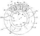
- FIG. 1is top view of the bearing assembly with a cut-away section
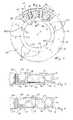
- FIG. 2is a cross-sectional view of the bearing assembly shown in FIG. 1 taken along line 2 — 2 ;
- FIG. 3is a cross-sectional view of the bearing assembly shown in FIG. 1 taken along line 3 — 3 ;
- FIG. 4is a bottom view of the bearing assembly shown in FIG. 1;
- FIG. 5is a cut-away perspective view of the bearing assembly shown in FIG. 1 .
- FIG. 1A bearing assembly 12 embodying the invention is illustrated in FIG. 1 .
- the bearing assembly 12includes a first race 14 having an axially extending section 16 and a radially extending section 18 .
- the first race 14has a substantially L-shaped configuration when viewed in cross section (as shown FIGS. 2-3 and 5 ).
- a second race 20(see FIG. 4 ), also having a substantially L-shaped configuration with an axially extending section 22 and a radially extending section 24 , is positioned adjacent the first race 14 .
- the axially extending section 16 of the first race 14is substantially plane parallel with the axially extending section 22 of the second race 20 .
- the radially extending section 18 of the first race 14is substantially plane parallel with the radially extending section 24 of the second race 20 .
- the bearing assembly 12is relatively enclosed by the races 14 and 20 .
- the races 14 and 20may include interlocking structure so that the bearing assembly forms a unit. However, in other constructions (not shown), the races 14 and 20 do not include interlocking structure, and such a bearing assembly may be assembled and disassembled.
- the bearing assembly 12has a first face 26 .
- a first annular gap 28extends circumferentially around the first face 26 .
- the first annular gap 28is defined by the axially extending section 22 of the second race 20 and by the radially extending section 18 of the first race 14 .
- the bearing assembly 12has (see FIG. 4) a second face 30 .
- a second annular gap 32extends circumferentially around the second face 30 .
- the second annular gap 32is defined by the axially extending section 16 of the first race 14 and by the radially extending section 24 of the second race 20 .
- the bearing assembly 12also includes a bearing retainer or cage 34 .
- the cage 34has body 36 and is positioned between and supported by the races 14 and 20 .
- the body 36has a substantially circular configuration and extends circumferentially about the axis A of the bearing assembly 12 .
- the body 36is substantially surrounded by the races 14 and 20 and is formed so that the body 36 has a number of axially spaced surfaces 37 .
- the body 36When viewed in longitudinal section, (as best seen in FIGS. 2, 3 , and 5 ) the body 36 has a substantially Sigma shape.
- a plurality of openings 38extend into or through the body 36 .
- the openings 38are circumferentially spaced about the body 36 .
- Each of the openings 38is adapted to receive a rolling element 40 .
- the rolling elements 40may be rollers, balls, wheels, or other similar friction reducing elements. In the illustrated construction, the rolling elements 40 are cylindrically-shaped roller bearing elements.
- a passage 42extends radially through a portion of the body 36 .
- FIG. 1shows a number of passages 42 spaced circumferentially around the body 36 and interspersed between the openings 38 .
- each passage 42extends a greater radial distance through the bearing assembly 12 than the openings 38 .
- Each passage 42includes an inlet 44 and an outlet 46 .
- Each inlet 44extends axially through the body 36 .
- each inlet 44is in fluid communication and axially aligned with the first annular gap 28 .
- Each outlet 46extends axially through the body 36 .
- each outlet 46is in fluid communication and axially aligned with the second annular gap 32 .
- the body 36also defines at least one and, preferably, two circular channels 48 .
- the channels 48extend circumferentially around the body 36 and are in fluid communication with the openings 38 and with the passages 42 .
- the bearing assembly 12is used in an apparatus (not shown), such as, for example, a torque converter.
- the bearing assembly 12is positioned between two relatively moving structures (not shown) of the apparatus.
- Lubricantis supplied to the bearing assembly 12 to lubricate the components of the bearing assembly 12 .
- Lubricantis also supplied through the bearing assembly 12 to lubricate the structures of the apparatus which are downstream of the bearing assembly 12 .
- Lubricantflows into the bearing assembly 12 through the inlets 44 .
- the lubricantflows through the channels 48 to each opening 38 . In this manner, the components of the bearing assembly 12 are lubricated.
- Lubricantalso flows radially through the bearing assembly 12 through the passages 42 .
- the lubricantflows out of the bearing assembly 12 to the downstream structures through the outlets 46 . Because the outlets 46 are axially aligned with the second, downstream annular gap 32 , the lubricant flows more freely from the bearing assembly 12 .
- the radial passages 42also improve flow of lubricant through the bearing assembly 12 .
Landscapes
- Engineering & Computer Science (AREA)
- General Engineering & Computer Science (AREA)
- Mechanical Engineering (AREA)
- Rolling Contact Bearings (AREA)
Abstract
Description
Claims (22)
Priority Applications (1)
| Application Number | Priority Date | Filing Date | Title |
|---|---|---|---|
| US10/007,626US6568857B1 (en) | 2001-11-08 | 2001-11-08 | Thrust bearing assembly |
Applications Claiming Priority (1)
| Application Number | Priority Date | Filing Date | Title |
|---|---|---|---|
| US10/007,626US6568857B1 (en) | 2001-11-08 | 2001-11-08 | Thrust bearing assembly |
Publications (2)
| Publication Number | Publication Date |
|---|---|
| US20030086632A1 US20030086632A1 (en) | 2003-05-08 |
| US6568857B1true US6568857B1 (en) | 2003-05-27 |
Family
ID=21727252
Family Applications (1)
| Application Number | Title | Priority Date | Filing Date |
|---|---|---|---|
| US10/007,626Expired - LifetimeUS6568857B1 (en) | 2001-11-08 | 2001-11-08 | Thrust bearing assembly |
Country Status (1)
| Country | Link |
|---|---|
| US (1) | US6568857B1 (en) |
Cited By (11)
| Publication number | Priority date | Publication date | Assignee | Title |
|---|---|---|---|---|
| US20060056753A1 (en)* | 2004-09-15 | 2006-03-16 | Honeywell International Inc. | High speed rolling element bearing anti-cavitation cage |
| US20090285518A1 (en)* | 2006-07-11 | 2009-11-19 | Schaeffler Kg | Axial rolling bearing |
| US20100008614A1 (en)* | 2006-07-17 | 2010-01-14 | Schaeffler Kg | Axial roller bearing |
| US8893513B2 (en) | 2012-05-07 | 2014-11-25 | Phononic Device, Inc. | Thermoelectric heat exchanger component including protective heat spreading lid and optimal thermal interface resistance |
| US8991194B2 (en) | 2012-05-07 | 2015-03-31 | Phononic Devices, Inc. | Parallel thermoelectric heat exchange systems |
| DE102014209236A1 (en)* | 2014-05-15 | 2015-11-19 | Schaeffler Technologies AG & Co. KG | Axial rolling bearing and Axialwälzlagerkäfig |
| US20160265592A1 (en)* | 2013-10-22 | 2016-09-15 | Schaeffler Technologies AG & Co. KG | Axial cage for cylindrical rolling elements |
| US9528592B2 (en) | 2012-06-26 | 2016-12-27 | Kinetech Power Company Llc | Solid-lubricated bearing assembly |
| US9593871B2 (en) | 2014-07-21 | 2017-03-14 | Phononic Devices, Inc. | Systems and methods for operating a thermoelectric module to increase efficiency |
| US10458683B2 (en) | 2014-07-21 | 2019-10-29 | Phononic, Inc. | Systems and methods for mitigating heat rejection limitations of a thermoelectric module |
| DE102020121938A1 (en) | 2020-08-21 | 2022-02-24 | Schaeffler Technologies AG & Co. KG | Thrust bearing disk and thrust bearing with such a thrust bearing disk |
Families Citing this family (6)
| Publication number | Priority date | Publication date | Assignee | Title |
|---|---|---|---|---|
| DE102008018291A1 (en)* | 2007-06-13 | 2008-12-18 | Schaeffler Kg | Rolling bearing cage with SIGMA shape |
| FR2941753B1 (en)* | 2009-02-05 | 2012-01-20 | Skf Ab | CAGE FOR BEARING BEARING |
| EP2959177B1 (en) | 2013-02-20 | 2019-10-30 | United Technologies Corporation | Rolling element bearing configured with a gutter and one or more fluid passages |
| DE102013223748A1 (en)* | 2013-11-21 | 2015-05-21 | Schaeffler Technologies AG & Co. KG | Cage for a needle bearing and associated needle roller bearing |
| CN112412985B (en)* | 2019-08-20 | 2022-09-02 | 上银科技股份有限公司 | Retainer and bearing |
| DE102021115029A1 (en) | 2021-06-10 | 2022-12-15 | Schaeffler Technologies AG & Co. KG | Rolling element cage for an axial bearing arrangement and axial bearing arrangement with such a rolling element cage |
Citations (10)
| Publication number | Priority date | Publication date | Assignee | Title |
|---|---|---|---|---|
| US1913275A (en) | 1929-11-11 | 1933-06-06 | Bantam Ball Bearing Company | Antifriction bearing |
| US2718440A (en) | 1953-02-07 | 1955-09-20 | Brinkmann Heinrich | Cage for axially loaded anti-friction bearings |
| US3414342A (en) | 1967-02-06 | 1968-12-03 | Rollway Bearing Company Inc | Self-lubricating thrust bearing |
| GB1175109A (en)* | 1966-09-16 | 1969-12-23 | Wilhelm Schaeffler | Grease-Lubricated Thrust Bearing |
| US4968157A (en) | 1988-12-15 | 1990-11-06 | Nippon Seiko Kabushiki Kaisha | Bearing lubricating system |
| US5356227A (en) | 1989-06-29 | 1994-10-18 | Tribology Systems, Inc. | Solid-lubricated bearing assembly |
| US5529401A (en) | 1993-11-22 | 1996-06-25 | Skf Industrial Trading And Development Company B.V. | Rolling element bearing comprising an oil containing matrix |
| US5630670A (en) | 1995-06-03 | 1997-05-20 | INA W alzlager Schaeffler KG | Axial rolling bearing |
| US5927868A (en) | 1997-12-19 | 1999-07-27 | The Torrington Company | Thrust bearing assembly with misassembly tab |
| US6102580A (en) | 1999-04-05 | 2000-08-15 | The Torrington Company | Axial-thrust bearing with improved lubricant flow |
- 2001
- 2001-11-08USUS10/007,626patent/US6568857B1/ennot_activeExpired - Lifetime
Patent Citations (10)
| Publication number | Priority date | Publication date | Assignee | Title |
|---|---|---|---|---|
| US1913275A (en) | 1929-11-11 | 1933-06-06 | Bantam Ball Bearing Company | Antifriction bearing |
| US2718440A (en) | 1953-02-07 | 1955-09-20 | Brinkmann Heinrich | Cage for axially loaded anti-friction bearings |
| GB1175109A (en)* | 1966-09-16 | 1969-12-23 | Wilhelm Schaeffler | Grease-Lubricated Thrust Bearing |
| US3414342A (en) | 1967-02-06 | 1968-12-03 | Rollway Bearing Company Inc | Self-lubricating thrust bearing |
| US4968157A (en) | 1988-12-15 | 1990-11-06 | Nippon Seiko Kabushiki Kaisha | Bearing lubricating system |
| US5356227A (en) | 1989-06-29 | 1994-10-18 | Tribology Systems, Inc. | Solid-lubricated bearing assembly |
| US5529401A (en) | 1993-11-22 | 1996-06-25 | Skf Industrial Trading And Development Company B.V. | Rolling element bearing comprising an oil containing matrix |
| US5630670A (en) | 1995-06-03 | 1997-05-20 | INA W alzlager Schaeffler KG | Axial rolling bearing |
| US5927868A (en) | 1997-12-19 | 1999-07-27 | The Torrington Company | Thrust bearing assembly with misassembly tab |
| US6102580A (en) | 1999-04-05 | 2000-08-15 | The Torrington Company | Axial-thrust bearing with improved lubricant flow |
Cited By (17)
| Publication number | Priority date | Publication date | Assignee | Title |
|---|---|---|---|---|
| US20060056753A1 (en)* | 2004-09-15 | 2006-03-16 | Honeywell International Inc. | High speed rolling element bearing anti-cavitation cage |
| US7144162B2 (en) | 2004-09-15 | 2006-12-05 | Honeywell International, Inc. | High speed rolling element bearing anti-cavitation cage |
| US20090285518A1 (en)* | 2006-07-11 | 2009-11-19 | Schaeffler Kg | Axial rolling bearing |
| US20100008614A1 (en)* | 2006-07-17 | 2010-01-14 | Schaeffler Kg | Axial roller bearing |
| US9310111B2 (en) | 2012-05-07 | 2016-04-12 | Phononic Devices, Inc. | Systems and methods to mitigate heat leak back in a thermoelectric refrigeration system |
| US8991194B2 (en) | 2012-05-07 | 2015-03-31 | Phononic Devices, Inc. | Parallel thermoelectric heat exchange systems |
| US9103572B2 (en) | 2012-05-07 | 2015-08-11 | Phononic Devices, Inc. | Physically separated hot side and cold side heat sinks in a thermoelectric refrigeration system |
| US8893513B2 (en) | 2012-05-07 | 2014-11-25 | Phononic Device, Inc. | Thermoelectric heat exchanger component including protective heat spreading lid and optimal thermal interface resistance |
| US9341394B2 (en) | 2012-05-07 | 2016-05-17 | Phononic Devices, Inc. | Thermoelectric heat exchange system comprising cascaded cold side heat sinks |
| US10012417B2 (en) | 2012-05-07 | 2018-07-03 | Phononic, Inc. | Thermoelectric refrigeration system control scheme for high efficiency performance |
| US9528592B2 (en) | 2012-06-26 | 2016-12-27 | Kinetech Power Company Llc | Solid-lubricated bearing assembly |
| US20160265592A1 (en)* | 2013-10-22 | 2016-09-15 | Schaeffler Technologies AG & Co. KG | Axial cage for cylindrical rolling elements |
| DE102014209236A1 (en)* | 2014-05-15 | 2015-11-19 | Schaeffler Technologies AG & Co. KG | Axial rolling bearing and Axialwälzlagerkäfig |
| US9593871B2 (en) | 2014-07-21 | 2017-03-14 | Phononic Devices, Inc. | Systems and methods for operating a thermoelectric module to increase efficiency |
| US10458683B2 (en) | 2014-07-21 | 2019-10-29 | Phononic, Inc. | Systems and methods for mitigating heat rejection limitations of a thermoelectric module |
| DE102020121938A1 (en) | 2020-08-21 | 2022-02-24 | Schaeffler Technologies AG & Co. KG | Thrust bearing disk and thrust bearing with such a thrust bearing disk |
| DE102020121938B4 (en)* | 2020-08-21 | 2024-10-10 | Schaeffler Technologies AG & Co. KG | Bearing arrangement with one axial bearing with one axial bearing disk |
Also Published As
| Publication number | Publication date |
|---|---|
| US20030086632A1 (en) | 2003-05-08 |
Similar Documents
| Publication | Publication Date | Title |
|---|---|---|
| US6568857B1 (en) | Thrust bearing assembly | |
| EP2659153B1 (en) | Cage for a roller bearing assembled from two wire rings and a plurality of stays or pins | |
| EP2541087B1 (en) | Rolling bearing inner ring with lubricating grooves on the inner surface | |
| US9103375B2 (en) | Cartridge bearing assembly | |
| WO2009131139A1 (en) | Rolling bearing | |
| US5547060A (en) | Pressurized radial bearings | |
| AU2007253124A1 (en) | Ball bearing cage | |
| JP2003294044A (en) | Oil feeder for rolling bearing | |
| US20100008614A1 (en) | Axial roller bearing | |
| JPH07167135A (en) | Roller with cage | |
| US4971184A (en) | Overrunning clutch with lubricant spreading and distribution means | |
| US10465745B2 (en) | Thrust roller bearing cage and thrust roller bearing | |
| EP2107261B1 (en) | Roller bearings and gas turbine engine systems involving such bearings | |
| US20160084312A1 (en) | Double-row roller bearing | |
| EP1390631B1 (en) | Package bearing with lubrication ports | |
| JP2912532B2 (en) | Needle roller with cage | |
| US20170370414A1 (en) | Ball bearing assembly with inner ring and lubrication therefor | |
| WO2014152390A1 (en) | Bearing assembly with lubricant/coolant passages | |
| GB2398107A (en) | Thrust roller bearing assembly | |
| US20190055988A1 (en) | Bearing cage with lubrication channel | |
| GB2361964A (en) | Retainer for roller type thrust bearing | |
| JP2003049843A (en) | Roller bearing | |
| JP2005291445A (en) | Tapered roller bearing | |
| WO2007129441A1 (en) | Multi-row rolling bearing device | |
| US9551374B2 (en) | Crankshaft |
Legal Events
| Date | Code | Title | Description |
|---|---|---|---|
| AS | Assignment | Owner name:TORRINGTON COMPANY, THE, CONNECTICUT Free format text:ASSIGNMENT OF ASSIGNORS INTEREST;ASSIGNORS:RICHARD, ERIC R.;MOULTON, DAVID R.;REEL/FRAME:012616/0147;SIGNING DATES FROM 20020114 TO 20020115 | |
| STCF | Information on status: patent grant | Free format text:PATENTED CASE | |
| FEPP | Fee payment procedure | Free format text:PAYOR NUMBER ASSIGNED (ORIGINAL EVENT CODE: ASPN); ENTITY STATUS OF PATENT OWNER: LARGE ENTITY | |
| FPAY | Fee payment | Year of fee payment:4 | |
| AS | Assignment | Owner name:TIMKEN US CORPORATION, OHIO Free format text:CHANGE OF NAME;ASSIGNOR:THE TORRINGTON COMPANY;REEL/FRAME:023519/0677 Effective date:20030218 | |
| AS | Assignment | Owner name:TIMKEN US LLC, OHIO Free format text:CHANGE OF NAME;ASSIGNOR:TIMKEN US CORPORATION;REEL/FRAME:023525/0151 Effective date:20080327 | |
| FEPP | Fee payment procedure | Free format text:PAYER NUMBER DE-ASSIGNED (ORIGINAL EVENT CODE: RMPN); ENTITY STATUS OF PATENT OWNER: LARGE ENTITY Free format text:PAYOR NUMBER ASSIGNED (ORIGINAL EVENT CODE: ASPN); ENTITY STATUS OF PATENT OWNER: LARGE ENTITY | |
| AS | Assignment | Owner name:KOYO BEARINGS USA LLC, OHIO Free format text:PATENT ASSIGNMENT AGREEMENT;ASSIGNOR:TIMKEN US LLC;REEL/FRAME:023810/0483 Effective date:20091231 Owner name:KOYO BEARINGS USA LLC,OHIO Free format text:PATENT ASSIGNMENT AGREEMENT;ASSIGNOR:TIMKEN US LLC;REEL/FRAME:023810/0483 Effective date:20091231 | |
| FPAY | Fee payment | Year of fee payment:8 | |
| AS | Assignment | Owner name:KOYO BEARINGS NORTH AMERICA LLC, OHIO Free format text:CHANGE OF NAME;ASSIGNOR:KOYO BEARINGS USA LLC;REEL/FRAME:033744/0787 Effective date:20130401 | |
| FPAY | Fee payment | Year of fee payment:12 |